JP6120988B2 - Display control apparatus and display control method - Google Patents
Display control apparatus and display control methodDownload PDFInfo
- Publication number
- JP6120988B2 JP6120988B2JP2015551342AJP2015551342AJP6120988B2JP 6120988 B2JP6120988 B2JP 6120988B2JP 2015551342 AJP2015551342 AJP 2015551342AJP 2015551342 AJP2015551342 AJP 2015551342AJP 6120988 B2JP6120988 B2JP 6120988B2
- Authority
- JP
- Japan
- Prior art keywords
- image
- icon
- gesture
- satisfied
- mode
- Prior art date
- Legal status (The legal status is an assumption and is not a legal conclusion. Google has not performed a legal analysis and makes no representation as to the accuracy of the status listed.)
- Active
Links
Images


Classifications
- G—PHYSICS
- G06—COMPUTING OR CALCULATING; COUNTING
- G06F—ELECTRIC DIGITAL DATA PROCESSING
- G06F3/00—Input arrangements for transferring data to be processed into a form capable of being handled by the computer; Output arrangements for transferring data from processing unit to output unit, e.g. interface arrangements
- G06F3/01—Input arrangements or combined input and output arrangements for interaction between user and computer
- G06F3/048—Interaction techniques based on graphical user interfaces [GUI]
- G06F3/0487—Interaction techniques based on graphical user interfaces [GUI] using specific features provided by the input device, e.g. functions controlled by the rotation of a mouse with dual sensing arrangements, or of the nature of the input device, e.g. tap gestures based on pressure sensed by a digitiser
- G06F3/0488—Interaction techniques based on graphical user interfaces [GUI] using specific features provided by the input device, e.g. functions controlled by the rotation of a mouse with dual sensing arrangements, or of the nature of the input device, e.g. tap gestures based on pressure sensed by a digitiser using a touch-screen or digitiser, e.g. input of commands through traced gestures
- G—PHYSICS
- G02—OPTICS
- G02B—OPTICAL ELEMENTS, SYSTEMS OR APPARATUS
- G02B27/00—Optical systems or apparatus not provided for by any of the groups G02B1/00 - G02B26/00, G02B30/00
- G02B27/0093—Optical systems or apparatus not provided for by any of the groups G02B1/00 - G02B26/00, G02B30/00 with means for monitoring data relating to the user, e.g. head-tracking, eye-tracking
- G—PHYSICS
- G06—COMPUTING OR CALCULATING; COUNTING
- G06F—ELECTRIC DIGITAL DATA PROCESSING
- G06F3/00—Input arrangements for transferring data to be processed into a form capable of being handled by the computer; Output arrangements for transferring data from processing unit to output unit, e.g. interface arrangements
- G06F3/01—Input arrangements or combined input and output arrangements for interaction between user and computer
- G06F3/017—Gesture based interaction, e.g. based on a set of recognized hand gestures
- H—ELECTRICITY
- H04—ELECTRIC COMMUNICATION TECHNIQUE
- H04N—PICTORIAL COMMUNICATION, e.g. TELEVISION
- H04N13/00—Stereoscopic video systems; Multi-view video systems; Details thereof
- H04N13/30—Image reproducers
- H04N13/302—Image reproducers for viewing without the aid of special glasses, i.e. using autostereoscopic displays
- H04N13/31—Image reproducers for viewing without the aid of special glasses, i.e. using autostereoscopic displays using parallax barriers
- H—ELECTRICITY
- H04—ELECTRIC COMMUNICATION TECHNIQUE
- H04N—PICTORIAL COMMUNICATION, e.g. TELEVISION
- H04N13/00—Stereoscopic video systems; Multi-view video systems; Details thereof
- H04N13/30—Image reproducers
- H04N13/398—Synchronisation thereof; Control thereof
- G—PHYSICS
- G06—COMPUTING OR CALCULATING; COUNTING
- G06F—ELECTRIC DIGITAL DATA PROCESSING
- G06F2203/00—Indexing scheme relating to G06F3/00 - G06F3/048
- G06F2203/041—Indexing scheme relating to G06F3/041 - G06F3/045
- G06F2203/04108—Touchless 2D- digitiser, i.e. digitiser detecting the X/Y position of the input means, finger or stylus, also when it does not touch, but is proximate to the digitiser's interaction surface without distance measurement in the Z direction
- H—ELECTRICITY
- H04—ELECTRIC COMMUNICATION TECHNIQUE
- H04N—PICTORIAL COMMUNICATION, e.g. TELEVISION
- H04N13/00—Stereoscopic video systems; Multi-view video systems; Details thereof
- H04N13/30—Image reproducers
- H04N2013/40—Privacy aspects, i.e. devices showing different images to different viewers, the images not being viewpoints of the same scene
- H04N2013/403—Privacy aspects, i.e. devices showing different images to different viewers, the images not being viewpoints of the same scene the images being monoscopic
Landscapes
- Engineering & Computer Science (AREA)
- General Engineering & Computer Science (AREA)
- Physics & Mathematics (AREA)
- Theoretical Computer Science (AREA)
- General Physics & Mathematics (AREA)
- Human Computer Interaction (AREA)
- Multimedia (AREA)
- Signal Processing (AREA)
- Optics & Photonics (AREA)
- User Interface Of Digital Computer (AREA)
Description
Translated fromJapanese本発明は、表示部を制御する表示制御装置及び表示制御方法に関するものである。 The present invention relates to a display control device and a display control method for controlling a display unit.
画面を見る方向によって異なる画像を一画面に表示可能な多重画像表示装置として、スプリットビュー(マルチビュー、デュアルビュー(登録商標)とも言う)方式の表示装置が知られており、近年、様々な分野においてスプリットビュー表示装置を適用することが提案されている。例えば、スプリットビュー表示装置と、その画面に配設されたタッチパネルとを、車載のナビゲーション装置に適用することが提案されている。このようなナビゲーション装置によれば、運転席側の方向と助手席側の方向とで異なる内容の画像を画面に表示するとともに、当該画像内に表示されているアイコンに対する操作をタッチパネルにて受け付けることが可能となる。 2. Description of the Related Art Split-view (also referred to as multi-view or dual-view (registered trademark)) type display devices are known as multi-image display devices capable of displaying different images on one screen depending on the viewing direction. Proposed to apply a split view display device. For example, it has been proposed to apply a split view display device and a touch panel disposed on the screen to an in-vehicle navigation device. According to such a navigation device, an image having different contents in the direction of the driver's seat and the direction of the passenger's seat is displayed on the screen, and an operation for the icon displayed in the image is received on the touch panel. Is possible.
しかしながら、上述のようなナビゲーション装置においては、運転席側の方向に表示される画像内のアイコンの位置と、助手席側の方向に表示される画像内のアイコンの位置とがスプリットビュー表示装置の画面上において重なっている場合がある。このような場合には、アイコンに対する操作をタッチパネルにて受け付けたとしても、運転席側の方向に表示されている画像内のアイコンに対して操作が実施されたのか、助手席側の方向に表示されている画像内のアイコンに対して操作が実施されたのかを判別できないという問題があった。 However, in the navigation device as described above, the position of the icon in the image displayed in the direction of the driver's seat and the position of the icon in the image displayed in the direction of the passenger's seat are determined by the split view display device. May overlap on the screen. In such a case, even if an operation on the icon is accepted on the touch panel, whether the operation is performed on the icon in the image displayed in the direction of the driver's seat is displayed in the direction of the passenger's seat There has been a problem that it is impossible to determine whether an operation has been performed on an icon in the displayed image.
そこで、特許文献1には、運転席側の方向に表示される画像内のアイコンの位置と、助手席側の方向に表示される画像内のアイコンの位置とが重ならないように、それらを互いに異なる位置に配置する技術が提案されている。 Therefore, in
しかしながら、例えば、運転者が、ドラッグ操作などの比較的広い範囲にわたる操作を実施した場合には、助手席側の方向に表示されている画像内のアイコンに対して知らないうちに操作を実施してしまうことがあるという問題があった。 However, for example, when the driver performs an operation over a relatively wide range such as a drag operation, the operation is performed without knowing the icon in the image displayed in the direction of the passenger seat. There was a problem that sometimes.
そこで、本発明は、上記のような問題点を鑑みてなされたものであり、ユーザが操作したことによって第2画像側(例えば助手席側)のアプリケーションの機能を知らないうちに実行してしまうことを抑制可能な技術を提供することを目的とする。 Therefore, the present invention has been made in view of the above-described problems, and is executed without knowing the function of the application on the second image side (for example, the passenger seat side) when operated by the user. It aims at providing the technology which can suppress this.
本発明に係る表示制御装置は、第1方向にて視認可能であるが第2方向にて視認できない第1画像と、第2方向にて視認可能であるが第1方向にて視認できない第2画像とを一つの画面上に表示可能な表示部を制御する表示制御装置であって、予め定められた条件が満たされたと判断した場合に当該満たされた条件に基づいて、アプリケーションの機能を実行するための第1画像内のアイコン及び当該アイコンを除くジェスチャー領域に対する第1ジェスチャー操作を含む第1操作と、アプリケーションの機能を実行するための第2画像内のアイコンに対する第2ジェスチャー操作を含む第2操作とを有効にする通常モード、及び、第1操作を制約せずに第2操作を制約する第2制約モードのうち、いずれか一つのモードに設定する制御部を備える。制御部は、指示体の三次元の位置を検出することによって第1操作と第2操作とを一律に受け付ける入力部からの出力信号に基づき、指示体が入力部から離間した状態で当該指示体によって予め定められた軌道を有する操作が実施されたと判定された場合に、条件が満たされたと判断して第2制約モードに設定する。The display control device according to the present invention includes a first image that is visible in the first direction but not visible in the second direction, and a second image that is visible in the second direction but not visible in the first direction. A display control device that controls a display unit that can display an image on a single screen, and executes a function of an application based on the satisfied condition when it is determined that a predetermined condition is satisfied A first operation including a first gesture operation for an icon in the first image and a gesture region excluding the icon, and a second gesture operation for an icon in the second image for executing the function of the application. normal mode to enable 2 operations and,and, in the second enforcement mode to constrain thesecond operationwithout constraintfirst operation, the control unit set to any one of modes Obtain.The control unit detects the three-dimensional position of the indicator, and based on the output signal from the input unit that uniformly receives the first operation and the second operation, the indicator in a state where the indicator is separated from the input unit. When it is determined that an operation having a predetermined trajectory has been performed, the condition is determined to be satisfied and the second constraint mode is set.
本発明によれば、予め定められた第1条件が満たされたと判断した場合に当該満たされた第1条件に基づいて、第2制約モード及び通常モードのうちいずれか一つのモードに設定する。したがって、第1方向のユーザが、操作したことによって第2画像側のアプリケーションの機能を知らないうちに実行してしまうことを抑制することができる。 According to the present invention, when it is determined that a predetermined first condition is satisfied, one of the second constraint mode and the normal mode is set based on the satisfied first condition. Therefore, it is possible to prevent the user in the first direction from executing the operation without knowing the function of the application on the second image side.
本発明の目的、特徴、態様、および利点は、以下の詳細な説明と添付図面とによって、より明白となる。 Objects, features, aspects, and advantages of the present invention will become more apparent from the following detailed description and the accompanying drawings.
<実施の形態1>
本発明の実施の形態1として、本発明に係る表示制御装置を、車両に搭載可能なナビゲーション装置に適用した場合を例にして説明する。図1は、当該ナビゲーション装置の構成の一例を示すブロック図である。以下、図1に示されるナビゲーション装置1が搭載された車両を「自車」と記載して説明する。<
As a first embodiment of the present invention, a case where the display control device according to the present invention is applied to a navigation device that can be mounted on a vehicle will be described as an example. FIG. 1 is a block diagram showing an example of the configuration of the navigation device. Hereinafter, the vehicle equipped with the
ナビゲーション装置1は、スプリットビュー表示部2と、タッチパネル3と、操作入力処理部9と、インタフェース部10と、記憶部11と、左用画像生成部12と、右用画像生成部13と、これらを統括的に制御する制御部14とを備えて構成されている。 The
インタフェース部10は、無線通信部4、スピーカ5、DVD(Digital Versatile Disk)プレーヤ6、エアコン7及び車内LAN(Local Area Network)8と、制御部14との間に接続されている。無線通信部4、スピーカ5、DVDプレーヤ6、エアコン7及び車内LAN8と、制御部14との間では、インタフェース部10を介して各種情報や各種信号が双方向に出力される。以下、説明を簡単にするため、一方がインタフェース部10を介して他方に情報を出力すると記載する代わりに、一方が他方に情報を出力すると記載する。制御部14は、制御情報を、無線通信部4、スピーカ5、DVDプレーヤ6、エアコン7及び車内LAN8に出力することにより、これらを制御することが可能となっている。 The
スプリットビュー表示部2は、例えば自車のダッシュボードなどに配設される。スプリットビュー表示部2は、左座席の方向(第1方向)にて視認可能であるが右座席の方向から視認できない第1画像(以下「左用画像」と記す)と、右座席の方向(第2方向)にて視認可能であるが左座席の方向から視認できない第2画像(以下「右用画像」と記す)とを一つの画面上に表示することが可能となっている。 The split
後述するように、スプリットビュー表示部2は、左用画像内のアイコン(第1アイコン)と、右用画像内のアイコン(第2アイコン)と、後述するジェスチャー操作が実施され、地図などが表示されるジェスチャー領域とを表示する。以下、左用画像内のアイコン(第1アイコン)を「左用アイコン」と記し、右用画像内のアイコン(第2アイコン)を「右用アイコン」と記す。また、以下では、左座席が運転席であり、右座席が助手席である構成を例にして説明するが、左座席が助手席であり、右座席が運転席である構成では、以下の説明において左と右とを互いに読み替えたものと同様である。 As will be described later, the split
スプリットビュー表示部2には、例えば、空間分割方式の表示装置が適用される。図2に当該表示装置の模式断面図を示す。図2に示す表示装置200は、表示画面201と、視差バリア202とを備えている。表示画面201には、左用画像を表示するための第1画素201aと、右用画像を表示するための第2画素201bとが水平方向(左右方向)に沿って交互に配置されている。視差バリア202は、左座席の方向に対しては第1画素201aの光を通過させるが第2画素201bの光を遮断し、右座席の方向に対しては第2画素201bの光を通過させるが第1画素201aの光を遮断する。このような構成によれば、左座席のユーザ101aは、右用画像を視認できないが左用画像を視認することができ、右座席のユーザ101bは、左用画像を視認できないが右用画像を視認することができる。 For example, a space-division display device is applied to the split
スプリットビュー表示部2に空間分割方式の表示装置200を適用した構成では、視差バリア202が左座席の方向に複数の第1画素201aからの光を通過させることによって左用アイコンが視認可能に表示され、視差バリア202が右座席の方向に複数の第2画素201bからの光を通過させることによって右用アイコンが視認可能に表示される。このため、左用アイコンの表示領域の外縁部は、当該左用アイコンの表示に用いられた複数の第1画素201aのうち外縁部に位置する第1画素201aに対応し、右用アイコンの表示領域の外縁部は、当該右用アイコンの表示に用いられた複数の第2画素201bのうち外縁部に位置する第2画素201bに対応する。 In the configuration in which the space
図3は、空間分割方式のスプリットビュー表示部2の表示例を示す図であり、1フレームの左用画像及び右用画像が示されている。例えば、WVGA(Wide VGA)の表示装置においては、全体で横(x軸)に800ドット、縦(y軸)に480ドットの画素を持つ。WVGAの表示装置に対応する、図3のような空間分割方式のスプリットビュー表示装置は、表示装置の性能によっても異なるが、例えば、横に並べられた総数がWVGAの表示装置における横方向の画素数の2倍、つまり合計の画素数が横に1600ドット、縦に480ドットの第1及び第2画素201a,201bで構成される。しかし、ここでは説明を容易にするため、スプリットビュー表示装置は、横に13ドット、縦に4ドットの第1画素201aと、それと同数の第2画素201bとで構成され、アイコンは横に4ドット、縦に1ドットの第1画素201aまたは第2画素201bで表示されるものとして説明を行う。また、図3に示されるようなアイコンの1ドットのx軸(左右方向)のずれは、通常の視認位置からでは人の目では見分けがつかず、同一位置に表示されているように見える。 FIG. 3 is a diagram illustrating a display example of the split
図3では、左用アイコンの外縁部(外枠)が破線で示されており、当該左用アイコンを表示するために、水平方向に配設された4つの第1画素201aが用いられていることが示されている。また、図3では、右用アイコンの外縁部(外枠)が一点鎖線で示されており、当該右用アイコンを表示するために、水平方向に配設された4つの第2画素201bが用いられていることが示されている。なお、左用アイコンの表示に用いられる第1画素201aの数、及び、右用アイコンの表示に用いられる第2画素201bの数は、4つに限ったものではない。また、図3には示されていないが、ジェスチャー領域の表示も、左用アイコン及び右用アイコンの表示と同様である。 In FIG. 3, the outer edge portion (outer frame) of the left icon is indicated by a broken line, and four
以下の説明では、スプリットビュー表示部2に空間分割方式の表示装置200が適用された構成において、左用アイコンの表示に用いられた複数(図3では4つ)の第1画素201aの少なくとも1つが、右用アイコンの表示に用いられた複数(図3では4つ)の第2画素201bのうち外縁部に位置する第2画素201b(図3では一点鎖線に対応する第2画素201b)に挟まれている場合に、当該左用アイコンの表示領域の少なくとも一部と、当該右用アイコンの表示領域の少なくとも一部とがスプリットビュー表示部2の画面上において互いに重なると記す。また、当該構成において、右用アイコンの表示に用いられた複数(図3では4つ)の第2画素201bの少なくとも1つが、左用アイコンの表示に用いられた複数(図3では4つ)の第1画素201aのうち外縁部に位置する第1画素201a(図3では破線に対応する第1画素201a)に挟まれている場合にも、当該左用アイコンの表示領域の少なくとも一部と、当該右用アイコンの表示領域の少なくとも一部とがスプリットビュー表示部2の画面上において互いに重なると記す。一方、当該構成において、右用アイコンの表示に用いられた第2画素201b、及び、左用アイコンの表示に用いられた第1画素201aの一方が、他方に挟まれていない場合に、当該左用アイコンの表示領域と、当該右用アイコンの表示領域とがスプリットビュー表示部2の画面上において離間すると記す。また、この記述は、左用アイコンと右用アイコンについてだけでなく、ジェスチャー領域と左用アイコンまたは右用アイコンとについても同様に記す。 In the following description, in the configuration in which the space
以上、スプリットビュー表示部2に、空間分割方式の表示装置200が適用された構成について説明した。しかしこれに限ったものではなく、スプリットビュー表示部2には、例えば、時分割方式の表示装置が適用されてもよい。図4に当該表示装置の模式断面図を示す。図4に示す表示装置250は、表示画面251と、視差バリア252とを備えている。表示画面251は、第1期間では左用画像を画素251cによって表示し、第2期間では右用画像を画素251cによって表示する。視差バリア252は、第1期間では左座席の方向に対して画素251cの光を通過させるが右座席の方向に対して画素251cの光を遮断し、第2期間では右座席の方向に対して画素251cの光を通過させるが左座席の方向に対して画素251cの光を遮断する。なお、図4には、第1期間の状態が示されている。 The configuration in which the space
上述のような構成によれば、左座席のユーザ101aは、右用画像を視認できないが左用画像を視認することができ、右座席のユーザ101bは、左用画像を視認できないが右用画像を視認することができる。なお、右座席のユーザ101bの目は、第1期間において、スプリットビュー表示部2から画素251cの光を受けていない。しかし、この第1期間は非常に短く設定されていることから、第1期間に目が光を受けていないことは右座席のユーザ101bに認識されない。一方、第2期間に目が受けた光の残像効果によって、第1期間においても第2期間の画像が表示されているように右座席のユーザ101bに認識される。同様に、第2期間に目が光を受けていないことは左座席のユーザ101aに認識されず、第1期間に目が受けた光の残像効果によって、第2期間においても第1期間の画像が表示されているように左座席のユーザ101aに認識される。 According to the configuration described above, the
スプリットビュー表示部2に時分割方式の表示装置250を適用した構成では、視差バリア252が、第1期間に左座席の方向に複数の画素251cからの光を通過させることによって左用アイコンが視認可能に表示され、第2期間に右座席の方向に複数の画素251cからの光を通過させることによって右用アイコンが視認可能に表示される。このため、左用アイコンの表示領域の外縁部は、当該左用アイコンの表示に用いられた複数の画素251cのうち外縁部に位置する画素251cに対応し、右用アイコンの表示領域の外縁部は、当該右用アイコンの表示に用いられた複数の画素251cのうち外縁部に位置する画素251cに対応する。 In the configuration in which the time
図5(a)及び図5(b)は、時分割方式のスプリットビュー表示部2の表示例を示す図であり、1フレームの左用画像及び右用画像が示されている。例えば、WVGAの表示装置においては、上述したように、全体で横(x軸)に800ドット、縦(y軸)に480ドットの画素を持つ。WVGAの表示装置に対応する、図5(a)及び図5(b)のような時分割方式のスプリットビュー表示装置は、表示装置の性能によっても異なるが、例えば、横に800ドット、縦に480ドットの画素251cで構成される。しかし、ここでは説明を容易にするため、スプリットビュー表示装置は、横に13ドット、縦に4ドットの画素251cで構成され、アイコンは横に3ドット、縦に1ドットの画素251cで表示されるものとして説明を行う。 FIG. 5A and FIG. 5B are diagrams showing a display example of the time-division split
図5(a)では、第1期間に表示される左用アイコンの外縁部(外枠)が破線で示されており、当該左用アイコンを表示するために、水平方向に配設された3つの画素251cが用いられていることが示されている。図5(b)では、第2期間に表示される右用アイコンの外縁部(外枠)が破線で示されており、当該右用アイコンを表示するために、水平方向に配設された3つの画素251cの一部が用いられていることが示されている。なお、左用アイコンの表示に用いられる画素251cの数、及び、右用アイコンの表示に用いられる画素251cの数は、3つに限ったものではない。また、図5(a)及び図5(b)には示されていないが、ジェスチャー領域の表示も、左用アイコン及び右用アイコンの表示と同様である。 In FIG. 5A, the outer edge (outer frame) of the left icon displayed in the first period is indicated by a broken line, and three pixels arranged in the horizontal direction to display the left icon. It is shown that 251c is used. In FIG. 5B, the outer edge portion (outer frame) of the right icon displayed in the second period is indicated by a broken line, and 3 arranged in the horizontal direction to display the right icon. It is shown that a part of one
以下の説明では、スプリットビュー表示部2に時分割方式の表示装置250が適用された構成において、第1期間に左用アイコンの表示に用いられた複数の画素251cのうち少なくとも1つと、第2期間に右用アイコンの表示に用いられた複数の画素251cのうち少なくとも1つとが一致する場合に、当該左用アイコンの表示領域の少なくとも一部と、当該右用アイコンの表示領域の少なくとも一部とがスプリットビュー表示部2の画面上において互いに重なると記す。一方、第1期間に左用アイコンの表示に用いられ、かつ、第2期間に右用アイコンの表示に用いられた画素251cが存在しない場合に、当該左用アイコンの表示領域と、当該右用アイコンの表示領域とがスプリットビュー表示部2の画面上において離間すると記す。また、この記述は、左用アイコンと右用アイコンについてだけでなく、ジェスチャー領域と左用アイコンまたは右用アイコンとについても同様に記す。 In the following description, in the configuration in which the time-
詳細な構成については説明を省略するが、スプリットビュー表示部2には、空間分割方式と時分割方式とを組み合わせた方式の表示装置が適用されてもよい。そして、例えば、第1期間に左用アイコンの表示に用いられた画素の少なくとも一部が、第2期間に右用アイコンの表示に用いられた複数の画素のうち外縁部に位置する画素に挟まれている場合、または、第2期間に右用アイコンの表示に用いられた画素の少なくとも一部が、第1期間に左用アイコンの表示に用いられた複数の画素のうち外縁部に位置する画素に挟まれている場合に、当該左用アイコンの表示領域の少なくとも一部と、当該右用アイコンの表示領域の少なくとも一部とがスプリットビュー表示部2の画面上において互いに重なると記す。一方、第1期間に左用アイコンの表示に用いられた画素、及び、第2期間に右用アイコンの表示に用いられた画素の一方が、他方に挟まれていない場合に、当該左用アイコンの表示領域と、当該右用アイコンの表示領域とがスプリットビュー表示部2の画面上において離間すると記す。また、この記述は、左用アイコンと右用アイコンについてだけでなく、ジェスチャー領域と左用アイコンまたは右用アイコンとについても同様に記す。 Although the description of the detailed configuration is omitted, the split
なお、スプリットビュー方式を用いた表示装置の具体的な構成は、例えば特開2005−078080号公報及び国際公開第2012/070444号などに開示されている。なお、以上の説明では言及しなかったが、空間分割方式及び時分割方式のいずれにおいても、短い期間(1/30[秒])で画素の走査が行われる。 Note that specific configurations of a display device using the split view method are disclosed in, for example, Japanese Patent Application Laid-Open No. 2005-078080 and International Publication No. 2012/070444. Although not mentioned in the above description, pixel scanning is performed in a short period (1/30 [second]) in both the space division method and the time division method.
図1に戻って、タッチパネル3の検出面は、スプリットビュー表示部2の画面に配設されている。タッチパネル3(入力部)は、アプリケーションの機能を実行するための左用画像に対する第1操作(以下「左用操作」)と、アプリケーションの機能を実行するための右用画像に対する第2操作(以下「右用操作」)とを一律に受け付ける。本実施の形態1に係るタッチパネル3は、図6に示すように、ユーザ(運転者及び助手席の同乗者)の指などの指示体との距離が最短となる検出面上の点の位置(X,Y)と、指示体と検出面(当該点)との間の距離Zとを含む三次元の位置(X,Y,Z)を、指示体の位置として検出する。 Returning to FIG. 1, the detection surface of the
指示体(図6では指21)とタッチパネル3の検出面との間の距離Zを示す。距離Z=0である場合には、指示体(図6では指21)がタッチパネル3の検出面を接触(タッチ)していることを意味する。 A distance Z between the indicator (
このようなタッチパネル3には、例えば、検出面と指示体との間に形成される静電容量に基づいて指示体の三次元の位置(検出面上の基準点に対する指示体の三次元の位置)を検出する静電式タッチパネルが適用される。タッチパネル3は、以上のような指示体の三次元の位置を定期的に検出し、当該三次元の位置を示す信号を、操作入力処理部9に出力する。 Such a
無線通信部4は、例えばDSRC(Dedicate Short Range Communication)及び携帯電話機などを介してサーバと通信を行う。無線通信部4は、サーバから受信した情報(例えばダウンロードした情報など)を制御部14に出力したり、制御部14から出力された情報をサーバに送信したりする。また、無線通信部4は、ラジオ放送及びテレビ放送を受信し、それら放送から取得した情報を制御部14に出力する。 The
スピーカ5(音声出力部)は、制御部14から出力された音声信号に基づいて音声を出力する。 The speaker 5 (sound output unit) outputs sound based on the sound signal output from the
DVDプレーヤ6は、DVDに記録されたAV(Audio-video)情報を再生し、当該AV情報を制御部14に出力する。 The
エアコン7は、制御部14の制御により、自車の室内の温度や湿度を調整する。 The air conditioner 7 adjusts the temperature and humidity in the vehicle interior under the control of the
車内LAN8は、自車のECU(Electronic Control Unit)やGPS(Global Positioning System)装置などと通信を行う。例えば、車内LAN8は、ECUから取得した自車の速度や、GPS装置から取得した自車の現在位置(例えば緯度及び経度)を制御部14に出力する。 The in-
操作入力処理部9には、スプリットビュー表示部2に表示されているアイコンの位置を示すアイコン位置情報が制御部14から入力される。操作入力処理部9は、当該アイコン位置情報と、タッチパネル3の出力信号(指示体の三次元の位置を示す信号)とに基づいて、タッチパネル3、ひいてはスプリットビュー表示部2に表示されているアイコンなどに対して操作が実施されたか否かを判定する。ここでは、操作入力処理部9は、タッチパネル3の出力信号が、距離Z=0を示し、かつ、当該出力信号が示す指示体の位置が、左用アイコンの表示領域に重なる(当該指示体が、当該左用アイコンの内側に位置する)と判定した場合には、当該左用アイコンに対する操作が実施されたと判定する。同様に、操作入力処理部9は、タッチパネル3の出力信号が、距離Z=0を示し、かつ、当該出力信号が示す指示体の位置が、右用アイコンの表示領域に重なる(当該指示体が、当該右用アイコンの内側に位置する)と判定した場合には、当該右用アイコンに対する操作が実施されたと判定する。そして、操作入力処理部9は、その判定結果を制御部14に出力する。 Icon position information indicating the position of the icon displayed on the split
また、操作入力処理部9は、タッチパネル3の出力信号(指示体の三次元の位置を示す信号)に基づいて、タッチパネル3の検出面に対するタッチ操作などのポインティング操作以外の予め定められたジェスチャー操作(以下「ジェスチャー操作」と略記する)が実施されたか否かを判定する。ここでは、操作入力処理部9は、タッチパネル3の出力信号が、距離Z=0を示し、かつ、当該出力信号が示す指示体の位置が、ジェスチャー領域に重なりながら変化する(当該指示体の二次元の位置(X,Y)が、当該ジェスチャー領域の内側に位置しながら変化する)と判定した場合には、当該ジェスチャー領域に対するジェスチャー操作が実施されたと判定する。そして、操作入力処理部9は、その判定結果を制御部14に出力する。 In addition, the operation
ジェスチャー操作は、例えば、指示体が予め定められた時間よりも短い時間で検出面を擦るフリック操作、指示体が予め定められた時間よりも長い時間で検出面を擦るドラッグ操作、及び、二つの指示体が検出面に接触した状態でそれらの間の距離を変更するピンチ操作などを含んでおり、後述する予め定められた第1ジェスチャー操作及び予め定められた第2ジェスチャー操作として適用される。なお、ドラッグ操作は、上述した操作に限ったものではなく、指示体がタッチパネルに触れたまま検出面を擦る操作として適用されてもよい。また、フリック操作は、上述した操作に限ったものではなく、指示体がタッチパネルに触れた状態からその検出面をはらう操作として適用されてもよい。また、ジェスチャー操作は、2点タッチ後に当該2点タッチの2点を続けて用いるジェスチャー操作を含んでもよく、または、2点タッチ後に当該2点タッチの2点のうち1点を離して残りの1点を続けて用いるジェスチャー操作を含んでもよい。 Gesture operations include, for example, a flick operation in which the indicator rubs the detection surface in a shorter time than a predetermined time, a drag operation in which the indicator rubs the detection surface in a longer time than a predetermined time, and two This includes a pinch operation for changing the distance between the indicators in contact with the detection surface, and is applied as a predetermined first gesture operation and a predetermined second gesture operation described later. The drag operation is not limited to the above-described operation, and may be applied as an operation of rubbing the detection surface while the indicator is touching the touch panel. Further, the flick operation is not limited to the above-described operation, and may be applied as an operation of touching the detection surface from a state where the indicator touches the touch panel. Further, the gesture operation may include a gesture operation in which two points of the two-point touch are continuously used after the two-point touch, or one point out of the two points of the two-point touch after the two-point touch is released and the remaining points are left. A gesture operation that uses one point continuously may be included.
以上のように本実施の形態1では、スプリットビュー表示部2に表示されているアイコンなどに対する操作が実施されたか否かを判定する処理を、操作入力処理部9によって実施するものとして説明するが、当該判定する処理は制御部14によって実施されてもよい。また、図1では、操作入力処理部9は、タッチパネル3及び制御部14とは別に設けられているが、これに限ったものではなく、タッチパネル3の機能としてタッチパネル3に備えられていてもよいし、制御部14の機能として制御部14に備えられていてもよい。 As described above, the first embodiment will be described on the assumption that the operation
記憶部11は、例えばハードディスクドライブ、DVD及びそのドライブ装置、ブルーレイディスク及びそのドライブ装置、または、半導体メモリなどの記憶装置から構成される。記憶部11は、制御部14が動作するのに必要なプログラムのほか、制御部14に用いられる情報を記憶している。制御部14に用いられる情報には、例えば、アプリケーション(アプリケーションソフトウェア)、アプリケーションの機能を実行する際に操作されるアイコンが配置された画像、及び、地図情報などが含まれる。なお、以下の説明では、アプリケーションの機能を実行する際に操作されるアイコンが配置された画像(例えば図10(a)及び図10(b)に対応する画像)を、「アイコン配置画像」と記す。「アイコン配置画像」は、地図情報にアイコンを表示した画像も含む。 The
左用画像生成部12は、制御部14から出力された表示情報に基づいて、左用画像を表示するための表示信号を生成し、当該表示信号をスプリットビュー表示部2に出力する。スプリットビュー表示部2は、左用画像生成部12から表示信号を受けると、当該表示信号に基づいて左用画像を表示する。 The left
右用画像生成部13は、制御部14から出力された表示情報に基づいて、右用画像を表示するための表示信号を生成し、当該表示信号をスプリットビュー表示部2に出力する。スプリットビュー表示部2は、右用画像生成部13から表示信号を受けると、当該表示信号に基づいて右用画像を表示する。 The right
ここで、左用画像生成部12が生成する表示信号には、左用画像に用いられる複数の画素のそれぞれに例えば(1,1)、(2,1)、…、(800,1)、(1,2)、…(800,2)、…、(800,480)という順序で割り当てられた画素番号が含まれている。同様に、右用画像生成部13が生成する表示信号にも、右用画像に用いられる複数の画素のそれぞれに例えば(1,1)、(1,2)、…、(800,480)という順序で割り当てられた画素番号が含まれる。このため、左用アイコンの表示に用いられる少なくとも1つの画素の画素番号と、右用アイコンの表示に用いられる少なくとも1つの画素の画素番号とが一致する場合には、当該左用アイコンの表示領域の少なくとも一部と、当該右用アイコンの表示領域の少なくとも一部とがスプリットビュー表示部2の画面上において互いに重なることに相当する。ここで、(x,y)は、当該画面上の左上を(1,1)とし、x軸は右方向を正、y軸は下方向を正としたxy座標に対応した画素位置を示す。 Here, the display signal generated by the left
制御部14は、例えばCPU(Central Processing Unit)から構成されており、当該CPUが記憶部11に記憶されたプログラムを実行することにより、ナビゲーション装置1にて様々なアプリケーションを実行すること、ひいては当該実行されたアプリケーションに応じてスピーカ5などを制御することが可能となっている。 The
例えば、制御部14は、ナビゲーションのアプリケーションを実行した場合には、自車の現在位置と、タッチパネル3の出力信号に基づく目的地と、地図情報とに基づいて現在位置から目的地までの経路を探索し、当該経路に沿った案内を表示するための表示情報、及び、当該案内を音声出力するための音声信号を生成する。この結果、上述の案内が左用画像または右用画像として表示されるとともに、上述の案内の音声がスピーカ5にて出力される。 For example, when the navigation application is executed, the
また、例えば、制御部14は、DVD再生のアプリケーションを実行した場合には、DVDプレーヤ6からのAV情報を表示するための表示情報、及び、AV情報を音声出力するための音声信号を生成する。この結果、DVDに記憶された映像が左用画像または右用画像として表示されるとともに、DVDに記憶された音声がスピーカ5にて出力される。 Further, for example, when a DVD playback application is executed, the
また、制御部14は、左用画像側にて実行可能な(左用画像側から実行可能な)1以上のアプリケーションに対応する1つのアイコン配置画像を記憶部11から取得し、当該取得したアイコン配置画像を左用画像として表示させる。これにより、当該アプリケーションの機能を左用画像側にて実行するための操作の対象となるアイコンが、スプリットビュー表示部2(左用画像)に表示される。以下、左用画像として表示可能なアイコン配置画像(例えば図8(a)に対応する画像)を「左用アイコン配置画像」と記す。なお、左用画像として表示されている左用アイコン配置画像内のアイコンは、上述の左用アイコンである。 In addition, the
同様に、制御部14は、右用画像側にて実行可能な(右用画像側から実行可能な)1以上のアプリケーションに対応する1つのアイコン配置画像を記憶部11から取得し、当該取得したアイコン配置画像を右用画像として表示させる。これにより、当該アプリケーションの機能を右用画像側にて実行するための操作の対象となるアイコンが、スプリットビュー表示部2(右用画像)に表示される。以下、右用画像として表示可能なアイコン配置画像(例えば図8(b)に対応する画像)を「右用アイコン配置画像」と記す。なお、右用画像として表示されている右用アイコン配置画像内のアイコンは、上述の右用アイコンである。 Similarly, the
さて、以上の構成要素からなる本実施の形態1に係るナビゲーション装置1には、上述の右用操作も上述の左用操作も制約せずに両方を有効にする通常モードと、上述の右用操作を制約する右制約モードとが規定されている。 Now, the
そして、制御部14は、予め定められた第1条件が満たされたと判断した場合に当該満たされた第1条件に基づいて、通常モード及び右制約モード(第2制約モード)のうちいずれか一つのモードに設定する。 Then, when the
<関連するナビゲーション装置>
ここでは、本実施の形態1に係るナビゲーション装置1と関連するナビゲーション装置(以下「関連ナビゲーション装置」と記す)について説明する。なお、関連ナビゲーション装置においても、図1で説明した構成要素と同一または類似するものについては同じ符号を付す。<Related navigation device>
Here, a navigation device (hereinafter referred to as “related navigation device”) related to the
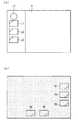
図7(a)及び図7(b)は、関連ナビゲーション装置(スプリットビュー表示部2)の左用画像及び右用画像の表示例を示す図である。図7(a)の左用画像には、左用アイコンL1,L2,L3(以下これらのアイコンをまとめて「左用アイコンL1〜L3」と記すこともある)と、上述のジェスチャー領域GLとが配置された左用アイコン配置画像が表示されている。図7(b)の右用画像には、右用アイコンR1,R2,R3,R4,R5(以下これらのアイコンをまとめて「右用アイコンR1〜R5」と記すこともある)が配置された右用アイコン配置画像が表示されている。 FIGS. 7A and 7B are diagrams illustrating display examples of the left image and the right image of the related navigation device (split view display unit 2). In the left image of FIG. 7A, left icons L1, L2, and L3 (hereinafter, these icons may be collectively referred to as “left icons L1 to L3”) and the gesture region GL described above are arranged. The left icon arrangement image is displayed. In the right image in FIG. 7B, right icons R1, R2, R3, R4, and R5 (hereinafter, these icons may be collectively referred to as “right icons R1 to R5”) are arranged. The icon arrangement image for the right is displayed.
さて、図7(a)及び図7(b)に示すような表示では、左用画像のジェスチャー領域GLの少なくとも一部と、右用アイコンR1〜R5の表示領域の少なくとも一部とはスプリットビュー表示部2の画面上において互いに重なっている。このため、関連ナビゲーション装置では、左座席のユーザ(運転者)がジェスチャー領域GLでジェスチャー操作を実施した場合には、知らないうちに右用アイコンR1〜R5に対しても操作を実施してしまうことがあるという問題があった。そこで、以下で説明するように、本実施の形態1に係るナビゲーション装置1によれば、左座席のユーザ(運転者)が、操作したことによって右用画像側のアプリケーションの機能を知らないうちに実行してしまうことを抑制することが可能となっている。 In the display as shown in FIGS. 7A and 7B, at least a part of the gesture area GL of the left image and at least a part of the display area of the right icons R1 to R5 are split view display. They overlap each other on the screen of
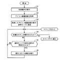
<本実施の形態1に係るナビゲーション装置の動作>
図8及び図9は、本実施の形態1に係るナビゲーション装置1の動作を示すフローチャートである。なお、図8及び図9に示される動作はCPUが記憶部11に記憶されたプログラムを実行することによって行われる。以下、ナビゲーション装置1の動作について図8及び図9を用いて説明する。<Operation of Navigation Device According to
8 and 9 are flowcharts showing the operation of the
まず、図8のステップS1にて、初期動作を実行するための操作が実施された場合に、制御部14は初期動作を実行する。ここでは、初期動作として、制御部14は、左用画像側及び右用画像側にて初期に実行すべきアプリケーションを記憶部11から取得し、当該アプリケーションを実行する。 First, when an operation for executing an initial operation is performed in step S1 of FIG. 8, the
ステップS2にて、制御部14は、左用画像側にて実行されているアプリケーションに対応する左用アイコン配置画像を記憶部11から取得するとともに、右用画像側にて実行されているアプリケーションに対応する右用アイコン配置画像を記憶部11から取得する。 In step S2, the
ステップS3にて、制御部14は、取得した左用アイコン配置画像をスプリットビュー表示部2の左用画像として表示し、取得した右用アイコン配置画像をスプリットビュー表示部2の右用画像として表示する。また、制御部14は通常モードに設定する。 In step S <b> 3, the
図10(a)及び図10(b)は、本実施の形態1に係るナビゲーション装置1(スプリットビュー表示部2)のステップS3における左用画像及び右用画像の表示例を示す図である。図10(a)の左用画像には、図7(b)の左用画像に、左優先ボタンLP(予め定められた第1ボタン)が追加されている。ここでは、左優先ボタンLPの表示領域は、右用アイコンR1〜R5の表示領域からスプリットビュー表示部2の画面上において離間して配置されているので、左優先ボタンLPに対する操作が実施されても、右用アイコンR1〜R5に対する操作が実施されることが抑制されている。図10(b)の右用画像は、図7(b)の右用画像と同じである。 FIGS. 10A and 10B are diagrams showing display examples of the left image and the right image in step S3 of the navigation device 1 (split view display unit 2) according to the first embodiment. In the left image in FIG. 10A, a left priority button LP (a predetermined first button) is added to the left image in FIG. 7B. Here, since the display area of the left priority button LP is arranged on the screen of the split
図8のステップS4にて、操作入力処理部9は、タッチパネル3からの出力信号に基づき、左用画像内の左優先ボタンLPに対する操作が実施されたか否かを判定する。左優先ボタンLPに対する操作が実施されなかったと判定された場合にはステップS5に進み、実施されたと判定された場合には図9のステップS7に進む。 In step S4 in FIG. 8, the operation
ステップS5にて、操作入力処理部9は、通常モードで有効な操作が実施されたか否かを判定する。ここでは、操作入力処理部9は、左用アイコンL1〜L3もしくは右用アイコンR1〜R5に対する操作、または、ジェスチャー領域GLに対するジェスチャー操作が実施されたか否かを判定する。実施されたと判定された場合にはステップS6に進み、実施されなかったと判定された場合にはステップS4に戻る。なお、ステップS4に戻る際において、地図が左用画像または右用画像として表示されており、かつ、自車の位置が変化していた場合には、制御部14は、当該変化に応じて当該地図をスクロールさせてもよい。このことは、ステップS5以外のステップからステップS4に戻る際においても同様である。 In step S5, the operation
ステップS6にて、制御部14は、実施された操作に応じた機能を実行する。ここでは、制御部14は、操作されたアイコンまたはジェスチャー領域に対応するアプリケーションの機能を実行する。その後ステップS4に戻る。なお、操作されたアイコンまたはジェスチャー領域に対して、アイコン配置画像が予め対応付けられて記憶部11に記憶されている場合には、ステップS6からステップS3に戻って、当該アイコン配置画像がスプリットビュー表示部2に表示されてもよい。 In step S6, the
図8のステップS4から図9のステップS7に進んだ場合、当該ステップS7にて、制御部14は、左優先ボタンLPに対する操作が実施されたとステップS4で判定されたことによって第1条件が満たされたと判断して、右用操作を制約する右制約モードに設定する。ここでは、制御部14は、左用操作として実施される第1ジェスチャー操作(例えばジェスチャー領域GLで受け付け可能なジェスチャー操作)を有効にし、かつ、右用操作として実施される第2ジェスチャー操作を無効にすることによって、右用操作を制約する。以下、左用操作として実施される第1ジェスチャー操作を「左ジェスチャー操作」と記し、右用操作として実施される第2ジェスチャー操作を「右ジェスチャー操作」と記す。なお、ここで有効にされる左ジェスチャー操作と、無効にされる右ジェスチャー操作とは同じジェスチャー操作が適用されてもよいし、異なるジェスチャー操作が適用されてもよい。 When the process proceeds from step S4 in FIG. 8 to step S7 in FIG. 9, in step S7, the
また、制御部14は、右用操作を制約していることをスプリットビュー表示部2に識別可能に表示させる。図11(a)及び図11(b)は、本実施の形態1に係るナビゲーション装置1のステップS7における左用画像及び右用画像の表示例を示す図である。 In addition, the
図11(a)に示されるように、制御部14は、左優先ボタンLPをステップS3の左優先ボタンLP(図10(a))よりも明るい色で表示させる(なお、以下においては、ハッチングの点の密度が高いほど暗い画像であることを意味するものとする)。 As shown in FIG. 11A, the
また、図11(b)に示されるように、制御部14は、右用アイコンR1〜R5を、ステップS3の右用アイコンR1〜R5(図10(b))よりも暗い色で表示させるとともに、右用画像の背景画像を、ステップS3の右用画像の背景画像(図10(b))よりも暗い色で表示させることにより、右用操作を制約していることを識別可能に表示させる。また、ステップS7にて表示される右用画像は、これに限ったものではなく、例えば、背景画像をぼかした画像であってもよいし、右用アイコンR1〜R5が表示されない画像であってもよい。 Further, as shown in FIG. 11B, the
図9のステップS8にて、操作入力処理部9は、ステップS4の判定を再度行う。すなわち、操作入力処理部9は、タッチパネル3からの出力信号に基づき、左用画像内の左優先ボタンLPに対する操作が実施されたか否かを再判定する。左優先ボタンLPに対する操作が実施されたと判定された場合にはステップS9に進み、実施されなかったと判定された場合にはステップS10に進む。 In step S8 in FIG. 9, the operation
ステップS9にて、制御部14は、左優先ボタンLPに対する操作が再度実施されたとステップS8で判定されたことによって第1条件が満たされたと判断して、通常モードに設定する。すなわち、制御部14は、右用操作の制約を解除する。そして、制御部14は、ステップS8の左用画像(図11(a))及び右用画像(図11(b))の表示からステップS3の元の左用画像(図10(a))及び元の右用画像(図10(b))の表示に戻す。その後、ステップS4に戻る。 In step S9, the
ステップS8からステップS10に進んだ場合、当該ステップS10にて、操作入力処理部9は、右制約モードで有効な操作(ここでは、左用アイコンL1〜L3に対する操作及びジェスチャー領域GLに対する左ジェスチャー操作などの左用操作)が実施されたか否かを判定する。右制約モードで有効な操作が実施されたと判定された場合にはステップS11に進み、実施されなかったと判定された場合にはステップS12に進む。 When the process proceeds from step S8 to step S10, in step S10, the operation
ステップS11にて、制御部14は、実施された操作に応じた機能を実行する。ここでは、制御部14は、操作されたアイコンまたはジェスチャー領域に対応するアプリケーションの機能を実行する。その後ステップS8に戻る。なお、操作されたアイコンまたはジェスチャー領域に対して、アイコン配置画像が予め対応付けられて記憶部11に記憶されている場合には、ステップS11からステップS3に戻って、当該アイコン配置画像がスプリットビュー表示部2に表示されてもよい。 In step S11, the
ステップS10からステップS12に進んだ場合、当該ステップS12にて、制御部14は、右制約モードに設定してから予め定められた時間までの間に左用操作に応じたアプリケーションの機能が実行されず、かつ通常モードに設定されなかったか否かを判断する。予め定められた時間までの間に実行及び設定のいずれも実行されなかったと判断した場合にはステップS9に進み、そうでない場合にはステップS8に戻る。 When the process proceeds from step S10 to step S12, in step S12, the
すなわち、ステップS12からステップS9に進んだ場合には、当該ステップS9にて、制御部14は、右制約モードに設定してから予め定められた時間までの間に左用操作に応じたアプリケーションの機能が実行されず、かつ通常モードに設定されなかったとステップS12で判断したことによって第1条件が満たされたと判断して、通常モードに設定する。 In other words, when the process proceeds from step S12 to step S9, in step S9, the
<効果>
以上のような本実施の形態1に係るナビゲーション装置1によれば、予め定められた第1条件が満たされたと判断した場合に当該満たされた第1条件に基づいて、通常モード及び右制約モードのうち、いずれか一つのモードに設定する。したがって、左座席のユーザ(運転者)が、操作したことによって右用画像側のアプリケーションの機能を知らないうちに実行してしまうことを抑制することができる。<Effect>
According to the
また、本実施の形態1によれば、タッチパネル3からの出力信号に基づき左用画像内の左優先ボタンLPに対する操作が実施されたと判定された場合に、第1条件が満たされたと判断して右用操作を制約する右制約モードに設定する。したがって、左座席のユーザ(運転者)は、左優先ボタンLPを操作した後は通常モードが設定されるまで、右用画像側のアプリケーションの機能を実行してしまうことを気にせずに操作することができる。 Further, according to the first embodiment, when it is determined that the operation on the left priority button LP in the left image is performed based on the output signal from the
特に、以上に説明した本実施の形態1によれば、比較的広い範囲にわたる左ジェスチャー操作または右ジェスチャー操作の実施が想定される場合において、上述の効果は有効である。 In particular, according to the first embodiment described above, the above-described effects are effective when the left gesture operation or the right gesture operation over a relatively wide range is assumed.
また、本実施の形態1によれば、右制約モードに設定してから予め定められた時間までの間に左用操作に応じたアプリケーションの機能が実行されず、かつ通常モードに設定されなかった場合に、第1条件が満たされたと判断して通常モードに設定する。したがって、右用操作の制約を必要最小限に留めることができる。 Further, according to the first embodiment, when the function of the application corresponding to the left operation is not executed and the normal mode is not set between the time set in the right constraint mode and the predetermined time. Then, it is determined that the first condition is satisfied, and the normal mode is set. Therefore, the restriction on the right operation can be minimized.
なお、以上では、後述の変形例や実施の形態との都合上、図6のように指示体の三次元の位置(X,Y,Z)を検出できるタッチパネルを用いた構成について説明した。しかしこれに限ったものではなく、タッチした指示体の二次元の位置(X,Y)を検出できるタッチパネルを用いてもよい。 In the above, for the convenience of modifications and embodiments described later, the configuration using the touch panel that can detect the three-dimensional position (X, Y, Z) of the indicator as shown in FIG. 6 has been described. However, the present invention is not limited to this, and a touch panel that can detect the two-dimensional position (X, Y) of the touched indicator may be used.
なお、本実施の形態1では、左優先ボタンに対する操作が実施されたと判定された場合と、左優先ボタンに対する操作が再度実施されたと判定された場合と、右制約モードに設定してから予め定められた時間までの間に左用操作に応じたアプリケーションの機能が実行されず、かつ通常モードに設定されなかった場合とにおいて、制御部14は第1条件が満たされたと判断した。しかしこれに限ったものではなく、例えば、次に説明する変形例を適用することができる。 In the first embodiment, when it is determined that the operation for the left priority button has been performed, when it is determined that the operation for the left priority button has been performed again, and after setting to the right constraint mode, it is determined in advance. The
<実施の形態1の変形例1>
実施の形態1では、制御部14は、左優先ボタンLPに対する操作が実施されたと判定された場合に、第1条件が満たされたと判断して右制約モードに設定した。しかし、これに限ったものではなく、以下の第1例〜第4例に説明する構成であってもよい。<
In the first embodiment, when it is determined that the operation on the left priority button LP has been performed, the
第1例の構成では、タッチパネル3は、複数の指示体によって同時に複数点でタッチされた場合に、当該複数点のそれぞれの位置を示す信号を出力する。操作入力処理部9は、タッチパネル3からの出力信号に基づいて、複数の指示体が同時に複数点でタッチパネル3をタッチする操作(以下「多点タッチ操作」などと記す)が実施されたか否かを判定する。 In the configuration of the first example, when the
そして、制御部14は、複数の指示体による多点タッチ操作が実施されたと操作入力処理部9で判定された場合に、第1条件が満たされたと判断して右制約モードに設定する。以上のような第1例の構成によれば、例えば、図12に示すように、2本の指21による2点タッチ操作が実施された場合には、右制約モードに設定することができる。なお、第1例の構成では、図6のように指示体の三次元の位置(X,Y,Z)を検出できるタッチパネルを用いてもよいし、タッチした指示体の二次元の位置(X,Y)を検出できるタッチパネルを用いてもよい。 Then, when the operation
第2例の構成では、タッチパネル3は、実施の形態1と同様に、指示体の三次元の位置を示す信号を出力する。操作入力処理部9は、タッチパネル3からの出力信号に基づいて、タッチパネル3から離間した指示体によって予め定められた軌道を有する操作(以下「軌道操作」と記す)が実施されたか否かを判定する。軌道操作には、例えば、図6の距離Zの変化が予め定められた閾値以下であり、かつ、二次元の位置(X,Y)の変化が予め定められた閾値以上である操作、タッチパネル3の検出面に対して平行または略平行に移動する操作、タッチパネル3の検出面から離れた位置で指によって円を描くような操作などが適用される。 In the configuration of the second example, the
そして、制御部14は、指示体による軌道操作が実施されたと操作入力処理部9で判定された場合に、第1条件が満たされたと判断して右制約モードに設定する。以上のような第2例の構成によれば、軌道操作が実施された場合には、右制約モードに設定することができる。 Then, when the operation
第3例の構成では、タッチパネル3は、上述の距離Zの代わりに、指示体によって検出面が押し込まれた量(押し込み量)を検出し、当該検出結果を示す信号を出力する。操作入力処理部9は、タッチパネル3からの出力信号が示す押し込み量が予め定められた値以下である場合には、タッチ操作が実施されたと判定し、押し込み量が予め定められた値よりも大きい場合には、押し込み操作が実施されたと判定する。 In the configuration of the third example, the
そして、制御部14は、指示体による押し込み操作が実施されたと判定された場合に、第1条件が満たされたと判断して右制約モードに設定する。以上のような第3例の構成によれば、例えば、指によって押し込み操作が実施された場合には、右制約モードに設定することができる。なお、この構成において、タッチ操作と押し込み操作とを互いに置き換えてもよい。すなわち、制御部14は、指示体によるタッチ操作が実施されたと判定された場合に、第1条件が満たされたと判断して右制約モードに設定してもよい。 And when it determines with the pushing operation by the indicator having been implemented, the
第4例の構成では、タッチパネル3は、実施の形態1と同様に、指示体の三次元の位置を示す信号を出力する。操作入力処理部9は、タッチパネル3からの出力信号に基づいて、指示体による操作(アイコン操作及びジェスチャー操作)が実施される直前の行為(予め定義された行為)が実施されたまたは実施中であるかを判定する。例えば、操作入力処理部9は、上述の距離Z(図6)が予め定められた閾値Z1(例えば3〜10cm程度)以下になった場合に、当該予め定義された行為が実施されたまたは実施中であると判定する。なお、実施中であると判定される行為は、実施されたと判定された上述の行為から継続する行為であってもよいし、継続しない行為であってもよい。 In the configuration of the fourth example, the
制御部14は、操作が実施される直前の行為が実施されたまたは実施中であると操作入力処理部9で判定された場合、すなわち距離Zが閾値Z1以下になった場合には、図13(a)及び図13(b)に示す表示をスプリットビュー表示部2に表示させる。具体的には、制御部14は、左用画像において右用アイコンR1〜R5に対応する領域RA1〜RA5を識別可能に表示させるとともに、右用画像において左用アイコンL1〜L3及びジェスチャー領域GLに対応する領域LA1〜LA3及び領域GLAを識別可能に表示させる。 When the operation
操作入力処理部9は、タッチパネル3からの出力信号に基づいて、背景画像(左用アイコンL1〜L3、ジェスチャー領域GL及び右用アイコンR1〜R5以外の画像、換言すれば領域LA1〜LA3,GLA,RA1〜RA5以外の画像)に対する操作(例えばタッチ操作)が実施されたか否かを判定する。 Based on the output signal from the
そして、制御部14は、図13(a)及び図13(b)に示すような背景画像に対する操作が実施されたと操作入力処理部9で判定された場合には、第1条件が満たされたと判断して右制約モードに設定する。以上のような第4例の構成によれば、例えば、指によって背景画像に対する操作が実施された場合には、右制約モードに設定することができる。また、タッチするごとに、通常モードと右制約モードとを切り替えるようにしてもよい。また、現在のモードを示す表示を行なってもよい。 When the operation
以上、第1例〜第4例の構成について説明したが、これらの構成によっても、実施の形態1と同様の効果を得ることができる。また、これらの構成によれば、左優先ボタンLPを左用画像(左用アイコン配置画像)から省くことができる。 Although the configurations of the first to fourth examples have been described above, the same effects as those of the first embodiment can be obtained also with these configurations. Further, according to these configurations, the left priority button LP can be omitted from the left image (left icon arrangement image).
また、上述の第1〜第4例とは別に、例えば、制御部14は、予め定められた時間内における同一点への指示体による複数回のタッチ操作が実施されたと操作入力処理部9で判定された場合に、第1条件が満たされたと判断して右制約モードに設定してもよい。また、例えば、制御部14は、予め定められた時間以上継続して、指示体によってタッチされたと操作入力処理部9で判定された場合に、第1条件が満たされたと判断して右制約モードに設定してもよい。 In addition to the first to fourth examples described above, for example, the
<実施の形態1の変形例2>
実施の形態1に係る制御部14は、右制約モードに設定する場合には、左ジェスチャー操作を有効にし、かつ、右ジェスチャー操作を無効にした(図9のステップS7)。<
When setting to the right constraint mode, the
これに対し、本変形例2に係る制御部14は、右制約モードに設定する場合には、左用画像側にて実行されているアプリケーションの種類に基づいて、左ジェスチャー操の種類、及び、右ジェスチャー操作の種類を変更するように構成されている。 On the other hand, when the
例えば、制御部14は、左用画像側にて実行されているアプリケーションがナビゲーション機能のアプリケーションである際に右制約モードに設定する場合には、有効となる左ジェスチャー操作にドラッグ操作を適用し、かつ、無効となる右ジェスチャー操作にドラッグ操作を適用してもよい。一方、制御部14は、左用画像側にて実行されているアプリケーションがDVD再生機能のアプリケーションである際に右制約モードに設定する場合には、有効となる左ジェスチャー操作にフリック操作を適用し、かつ、無効となる右ジェスチャー操作にフリック操作を適用してもよい。 For example, the
また、制御部14は、左用画像側にて実行されているアプリケーションの種類に基づいて、有効となる左ジェスチャー操作の数、及び、無効となる右ジェスチャー操作の数も変更してもよい。 Further, the
例えば、制御部14は、左用画像側にて実行されているアプリケーションがナビゲーション機能のアプリケーションである際に右制約モードに設定する場合には、有効となる左ジェスチャー操作に2つのジェスチャー操作(例えばドラッグ操作及びピンチ操作)を適用し、かつ、無効となる右ジェスチャー操作に当該2つのジェスチャー操作を適用する。そして、制御部14は、左用画像側にて実行されているアプリケーションがDVD再生機能のアプリケーションである際に右制約モードに設定する場合には、有効となる左ジェスチャー操作に1つのジェスチャー操作(例えばフリック操作)を適用し、かつ、無効となる右ジェスチャー操作に当該1つのジェスチャー操作を適用にしてもよい。また、右側のアプリケーションが必要とするジェスチャー操作を、右側のアプリケーションでは無効(禁止)するようにしてもよい。 For example, when the application executed on the left image side is a navigation function application and the
以上の内容を概括すると、本変形例2に係る制御部14は、左用画像側にて実行されているアプリケーションの種類に基づいて、左ジェスチャー操作及び右ジェスチャー操作を変更するように構成されている。このような本変形例2に係る構成によれば、有効にする左ジェスチャー操作、及び、無効にする右ジェスチャー操作を、適正化することができる。 In summary, the
なお、本変形例2の構成では、図6のように指示体の三次元の位置(X,Y,Z)を検出できるタッチパネルを用いてもよいし、タッチした指示体の二次元の位置(X,Y)を検出できるタッチパネルを用いてもよい。 In the configuration of the second modification, a touch panel capable of detecting the three-dimensional position (X, Y, Z) of the indicator as shown in FIG. 6 may be used, or the two-dimensional position of the touched indicator ( A touch panel capable of detecting X, Y) may be used.
<実施の形態2>
実施の形態1では、通常モード及び右制約モードが規定されていた。本発明の実施の形態2では、通常モード及び右制約モードだけでなく、左用操作を制約する左制約モード(第1制約モード)が追加されている。以下、本実施の形態2に係るナビゲーション装置1の構成について説明する。<
In the first embodiment, the normal mode and the right constraint mode are defined. In the second embodiment of the present invention, not only the normal mode and the right constraint mode, but also a left constraint mode (first constraint mode) that constrains the left operation is added. Hereinafter, the configuration of the
なお、本実施の形態2に係るナビゲーション装置1のブロック構成は、実施の形態1のブロック構成と同じであることから、その図示については省略する。そして、本実施の形態2に係るナビゲーション装置1において、実施の形態1で説明した構成要素と同一または類似するものについては同じ符号を付し、以下においては異なる点を中心に説明する。 Note that the block configuration of the
本実施の形態2に係る制御部14は、予め定められた第2条件が満たされたと判断した場合に当該満たされた第2条件に基づいて、右制約モード、左制約モード、及び、通常モードのうち、いずれか一つのモードに設定する。 When the
なお、ここでは、後述するように、左優先ボタンまたは右優先ボタンに対する操作が実施されたと判定された場合と、左優先ボタンまたは右優先ボタンに対する操作が再度実施されたと判定された場合と、右制約モードに設定してから予め定められた時間までの間に左用操作に応じたアプリケーションの機能が実行されず、かつ通常モード及び左制約モードのいずれにも設定されなかった場合と、左制約モードに設定してから予め定められた時間までの間に右用操作に応じたアプリケーションの機能が実行されず、かつ通常モード及び右制約モードのいずれにも設定されなかった場合とにおいて、制御部14は、上述の予め定められた第2条件が満たされたと判断するものとする。すなわち、本実施の形態2に係る第2条件は、実施の形態1に係る第1条件と一部が重複しているが、これに限ったものではなく、第2条件と第1条件とは完全に重複してもよく、第2条件と第1条件とは全く重複していなくてもよい。 Here, as will be described later, when it is determined that an operation on the left priority button or the right priority button is performed, when it is determined that an operation on the left priority button or the right priority button is performed again, If the function of the application corresponding to the left operation is not executed between the time when the restriction mode is set and the time is set in advance, and neither the normal mode nor the left restriction mode is set. In the case where the function of the application corresponding to the operation for the right is not executed during the period from the setting to the predetermined time and neither the normal mode nor the right constraint mode is set, the
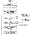
図14,図15及び図16は、本実施の形態2に係るナビゲーション装置1の動作を示すフローチャートである。なお、図14のステップS1及びS2では、実施の形態1のステップS1及びS2と同様の動作が行われるので、その説明については省略する。 14, FIG. 15 and FIG. 16 are flowcharts showing the operation of the
ステップS2後のステップS3にて、制御部14は、取得した左用アイコン配置画像をスプリットビュー表示部2の左用画像として表示し、取得した右用アイコン配置画像をスプリットビュー表示部2の右用画像として表示する。また、制御部14は通常モードに設定する。 In step S3 after step S2, the
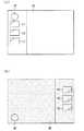
図17(a)及び図17(b)は、本実施の形態2に係るナビゲーション装置1のステップS3における左用画像及び右用画像の表示例を示す図である。図17(a)の左用画像は、図10(a)の左用画像と同じである。図17(b)の右用画像には、右用アイコンR1,R2,R3(以下これらのアイコンをまとめて「右用アイコンR1〜R3」と記すこともある)と、上述のジェスチャー領域GRと、右優先ボタンRP(予め定められた第2ボタン)とが配置された右用アイコン配置画像が表示されている。 FIGS. 17A and 17B are diagrams showing display examples of the left image and the right image in step S3 of the
なお、左用アイコンL1〜L3の表示領域の少なくとも一部と、右用画像のジェスチャー領域GRの少なくとも一部とはスプリットビュー表示部2の画面上において互いに重なっている。また、右用アイコンR1〜R3の表示領域の少なくとも一部と、左用画像のジェスチャー領域GLの少なくとも一部とはスプリットビュー表示部2の画面上において互いに重なっている。また、右優先ボタンRPは、左用アイコンL1〜L3からスプリットビュー表示部2の画面上において離間して配置されているので、右優先ボタンRPに対する操作が実施されても、左用アイコンL1〜L3などに対する操作が実施されることが抑制されている。また、右優先ボタンRPの表示領域の少なくとも一部は、左用画像のジェスチャー領域GLの少なくとも一部とスプリットビュー表示部2の画面上において重なっていない。したがって、右座席のユーザ(ここでは助手席の同乗者)が右優先ボタンRPを操作することが抑制され、左座席のユーザ(ここでは運転者)に悪影響を与えることが抑制されると考えられる。 Note that at least a part of the display area of the left icons L1 to L3 and at least a part of the gesture area GR of the right image overlap each other on the screen of the split
図14のステップS4aにて、操作入力処理部9は、タッチパネル3からの出力信号に基づき、左用画像内の左優先ボタンLPに対する操作が実施されたか否かを判定する。左優先ボタンLPに対する操作が実施されなかったと判定された場合にはステップS4bに進み、実施されたと判定された場合には図15のステップS7aに進む。 In step S4a in FIG. 14, the operation
ステップS4bにて、操作入力処理部9は、タッチパネル3からの出力信号に基づき、右用画像内の右優先ボタンRPに対する操作が実施されたか否かを判定する。右優先ボタンRPに対する操作が実施されなかったと判定された場合にはステップS5に進み、実施されたと判定された場合には図16のステップS7bに進む。 In step S <b> 4 b, the operation
なお、図14のステップS5及びS6では、実施の形態1のステップS5及びS6と同様の動作が行われるので、その説明については省略する。 In addition, in step S5 and S6 of FIG. 14, since the operation | movement similar to step S5 and S6 of
次に図15の動作について説明する。ステップS4aから図15のステップS7aに進んだ場合、当該ステップS7aにて、制御部14は、左優先ボタンLPに対する操作が実施されたとステップS4aで判定されたことによって第2条件が満たされたと判断して、右用操作を制約する右制約モードに設定する。ここでは、制御部14は、左ジェスチャー操作(例えばジェスチャー領域GLで受け付け可能なジェスチャー操作)を有効にし、かつ、右ジェスチャー操作を無効にすることによって右用操作を制約する。なお、ここで有効にされる左ジェスチャー操作と、無効にされる右ジェスチャー操作とは同じジェスチャー操作が適用されてもよいし、異なるジェスチャー操作が適用されてもよい。 Next, the operation of FIG. 15 will be described. When the process proceeds from step S4a to step S7a in FIG. 15, in step S7a, the
また、制御部14は、右用操作を制約していることをスプリットビュー表示部2に識別可能に表示させる。図18(a)及び図18(b)は、本実施の形態2に係るナビゲーション装置1のステップS7aにおける左用画像及び右用画像の表示例を示す図である。 In addition, the
図18(a)に示されるように、制御部14は、左優先ボタンLPをステップS3の左優先ボタンLP(図17(a))よりも明るい色で表示させる。 As shown in FIG. 18A, the
また、図18(b)に示されるように、制御部14は、右用アイコンR1〜R3及びジェスチャー領域GRを、ステップS3の右用アイコンR1〜R3及びジェスチャー領域GR(図17(b))よりも暗い色で表示させるとともに、右用画像の背景画像を、ステップS3の右用画像の背景画像(図17(b))よりも暗い色で表示させる。さらに、制御部14は、右優先ボタンRPを、ステップS3の右優先ボタンRP(図17(b))よりも暗い色で表示させる。これにより、制御部14は、右用操作を制約していることを識別可能に表示させる。なお、ステップS7aに表示される右用画像は、これに限ったものではなく、例えば、背景画像をぼかした画像であってもよいし、右用アイコンR1〜R3などが表示されない画像であってもよい。また、ジェスチャー操作が無効(禁止)とされている場合は、ジェスチャー領域または背景を暗く表示し、タッチ操作が無効(禁止)とされている場合は、操作アイコンを暗く表示してもよい。このように表示する構成によれば、どの操作が無効(禁止)とされているかをユーザに認識させることができるという効果を奏する。 Also, as shown in FIG. 18B, the
図15のステップS8aにて、操作入力処理部9は、ステップS4aの判定を再度行う。すなわち、操作入力処理部9は、タッチパネル3からの出力信号に基づき、左用画像内の左優先ボタンLPに対する操作が実施されたか否かを再判定する。左優先ボタンLPに対する操作が実施されたと判定された場合にはステップS9aに進み、実施されなかったと判定された場合にはステップS10aに進む。 In step S8a in FIG. 15, the operation
ステップS9aにて、制御部14は、左優先ボタンLPに対する操作が再度実施されたとステップS8aで判定されたことによって第2条件が満たされたと判断して、通常モードに設定する。すなわち、制御部14は、右用操作の制約を解除する。そして、制御部14は、ステップS7aの左用画像(図18(a))及び右用画像(図18(b))の表示からステップS3の元の左用画像(図17(a))及び元の右用画像(図17(b))の表示に戻す。その後、ステップS4aに戻る。 In step S9a, the
ステップS8aからステップS10aに進んだ場合、当該ステップS10aにて、操作入力処理部9は、右制約モードで有効な操作(ここでは、左用アイコンL1〜L3に対する操作及びジェスチャー領域GLに対する左ジェスチャー操作などの左用操作)が実施されたか否かを判定する。右制約モードで有効な操作が実施されたと判定された場合にはステップS11aに進み、実施されなかったと判定された場合にはステップS12aに進む。 When the process proceeds from step S8a to step S10a, in step S10a, the operation
ステップS11aにて、制御部14は、実施された操作に応じた機能を実行する。ここでは、制御部14は、操作されたアイコンまたはジェスチャー領域に対応するアプリケーションの機能を実行する。その後ステップS8aに戻る。なお、操作されたアイコンまたはジェスチャー領域に対して、アイコン配置画像が予め対応付けられて記憶部11に記憶されている場合には、ステップS11aからステップS3に戻って、当該アイコン配置画像がスプリットビュー表示部2に表示されてもよい。 In step S11a, the
ステップS10aからステップS12aに進んだ場合、当該ステップS12aにて、制御部14は、右制約モードに設定してから予め定められた時間までの間に左用操作に応じたアプリケーションの機能が実行されず、かつ通常モード及び左制約モードのいずれにも設定されなかったか否かを判断する。予め定められた時間までの間に実行及び設定のいずれも実行されなかったと判断した場合にはステップS9aに進み、そうでない場合にはステップS8aに戻る。 When the process proceeds from step S10a to step S12a, in step S12a, the
すなわち、ステップS12aからステップS9aに進んだ場合には、当該ステップS9aにて、制御部14は、右制約モードに設定してから予め定められた時間までの間に左用操作に応じたアプリケーションの機能が実行されず、かつ通常モード及び左制約モードのいずれにも設定されなかったとステップS12aで判断したことによって第2条件が満たされたと判断して、通常モードに設定する。 That is, when the process proceeds from step S12a to step S9a, in step S9a, the
次に図16の動作について説明する。ステップS4bから図16のステップS7bに進んだ場合、当該ステップS7bにて、制御部14は、右優先ボタンRPに対する操作が実施されたとステップS4bで判定されたことによって第2条件が満たされたと判断して、左用操作を制約する左制約モードに設定する。ここでは、制御部14は、右ジェスチャー操作(例えばジェスチャー領域GRで受け付け可能なジェスチャー操作)を有効にし、かつ、左ジェスチャー操作を無効にすることによって左用操作を制約する。なお、ここで有効にされる右ジェスチャー操作と、無効にされる左ジェスチャー操作とは同じジェスチャー操作が適用されてもよいし、異なるジェスチャー操作が適用されてもよい。 Next, the operation of FIG. 16 will be described. When the process proceeds from step S4b to step S7b in FIG. 16, in step S7b, the
また、制御部14は、左用操作を制約していることをスプリットビュー表示部2に識別可能に表示させる。図19(a)及び図19(b)は、本実施の形態2に係るナビゲーション装置1のステップS7bにおける左用画像及び右用画像の表示例を示す図である。 Further, the
図19(b)に示されるように、制御部14は、右優先ボタンRPをステップS3の右優先ボタンRP(図17(b))よりも明るい色で表示させる。 As shown in FIG. 19B, the
また、図19(a)に示されるように、制御部14は、左用アイコンL1〜L3及びジェスチャー領域GLを、ステップS3の左用アイコンL1〜L3及びジェスチャー領域GL(図17(a))よりも暗い色で表示させるとともに、左用画像の背景画像を、ステップS3の左用画像の背景画像(図17(a))よりも暗い色で表示させる。さらに、制御部14は、左優先ボタンLPを、ステップS3の左優先ボタンLP(図17(a))よりも暗い色で表示させる。これにより、制御部14は、左用操作を制約していることを識別可能に表示させる。なお、ステップS7bに表示される左用画像は、これに限ったものではなく、例えば、背景画像をぼかした画像であってもよいし、左用アイコンL1〜L3などが表示されない画像であってもよい。また、ジェスチャー操作が無効(禁止)されている場合は、ジェスチャー領域または背景を暗く表示し、タッチ操作が無効(禁止)されている場合は、操作アイコンを暗く表示してもよい。このように表示する構成によれば、どの操作が無効(禁止)されているかをユーザに認識させることができるという効果を奏する。 Further, as shown in FIG. 19A, the
図16のステップS8bにて、操作入力処理部9は、ステップS4bの判定を再度行う。すなわち、操作入力処理部9は、タッチパネル3からの出力信号に基づき、右用画像内の右優先ボタンRPに対する操作が実施されたか否かを再判定する。右優先ボタンRPに対する操作が実施されたと判定された場合にはステップS9bに進み、実施されなかったと判定された場合にはステップS10bに進む。 In step S8b in FIG. 16, the operation
ステップS9bにて、制御部14は、右優先ボタンRPに対する操作が再度実施されたとステップS8bで判定されたことによって第2条件が満たされたと判断して、通常モードに設定する。すなわち、制御部14は、左用操作の制約を解除する。そして、制御部14は、ステップS7bの左用画像(図19(a))及び右用画像(図19(b))の表示からステップS3の元の左用画像(図17(a))及び元の右用画像(図17(b))の表示に戻す。その後、ステップS4aに戻る。 In step S9b, the
ステップS8bからステップS10bに進んだ場合、当該ステップS10bにて、操作入力処理部9は、左制約モードで有効な操作(ここでは、右用アイコンR1〜R3に対する操作及びジェスチャー領域GRに対する右ジェスチャー操作などの右用操作)が実施されたか否かを判定する。左制約モードで有効な操作が実施されたと判定された場合にはステップS11bに進み、実施されなかったと判定された場合にはステップS12bに進む。 When the process proceeds from step S8b to step S10b, in step S10b, the operation
ステップS11bにて、制御部14は、実施された操作に応じた機能を実行する。ここでは、制御部14は、操作されたアイコンまたはジェスチャー領域に対応するアプリケーションの機能を実行する。その後ステップS8bに戻る。なお、操作されたアイコンまたはジェスチャー領域に対して、アイコン配置画像が予め対応付けられて記憶部11に記憶されている場合には、ステップS11bからステップS3に戻って、当該アイコン配置画像がスプリットビュー表示部2に表示されてもよい。 In step S11b, the
ステップS10bからステップS12bに進んだ場合、当該ステップS12bにて、制御部14は、左制約モードに設定してから予め定められた時間までの間に右用操作に応じたアプリケーションの機能が実行されず、かつ通常モード及び右制約モードのいずれにも設定されなかったか否かを判断する。予め定められた時間までの間に実行及び設定のいずれも実行されなかったと判断した場合にはステップS9bに進み、そうでない場合にはステップS8bに戻る。 When the process proceeds from step S10b to step S12b, in step S12b, the
すなわち、ステップS12bからステップS9bに進んだ場合には、当該ステップS9bにて、制御部14は、左制約モードに設定してから予め定められた時間までの間に右用操作に応じたアプリケーションの機能が実行されず、かつ通常モード及び右制約モードのいずれにも設定されなかったとステップS12bで判断したことによって第2条件が満たされたと判断して、通常モードに設定する。 That is, when the process proceeds from step S12b to step S9b, in step S9b, the
<効果>
以上のような本実施の形態2に係るナビゲーション装置1によれば、予め定められた第2条件が満たされたと判断した場合に当該満たされた第2条件に基づいて、右制約モード、左制約モード及び通常モードのうち、いずれか一つのモードに設定する。したがって、左座席のユーザ(運転者)が操作したことによって右用画像側のアプリケーションの機能を知らないうちに実行してしまうことを抑制することができるとともに、右座席のユーザ(助手席の同乗者)が操作したことによって左用画像側のアプリケーションの機能を知らないうちに実行してしまうことを抑制することができる。<Effect>
According to the
また、本実施の形態2によれば、左優先ボタンLPに対する操作が実施されたと判定された場合に、第2条件が満たされたと判断して右用操作を制約する右制約モードに設定し、右優先ボタンRPに対する操作が実施されたと判定された場合に、第2条件が満たされたと判断して左用操作を制約する左制約モードに設定する。したがって、左座席のユーザ(運転者)は、左優先ボタンLPを操作した後は通常モードが設定されるまで、右用画像側のアプリケーションの機能を実行してしまうことを気にせずに操作することができる。同様に、右座席のユーザ(助手席の同乗者)は、右優先ボタンRPを操作した後は通常モードが設定されるまで、左用画像側のアプリケーションの機能を実行してしまうことを気にせずに操作することができる。 Further, according to the second embodiment, when it is determined that the operation on the left priority button LP has been performed, it is determined that the second condition is satisfied, and the right restriction mode for restricting the right operation is set. When it is determined that the operation on the right priority button RP has been performed, it is determined that the second condition is satisfied, and the left restriction mode is set to restrict the left operation. Therefore, after operating the left priority button LP, the user (driver) in the left seat operates without worrying about executing the function of the application on the right image side until the normal mode is set. be able to. Similarly, the user in the right seat (passenger in the passenger seat) does not mind executing the function of the application on the left image side after operating the right priority button RP until the normal mode is set. Can be operated.
特に、以上に説明した本実施の形態2によれば、比較的広い範囲にわたる左ジェスチャー操作または右ジェスチャー操作の実施が想定される場合において、上述の効果は有効である。 In particular, according to the second embodiment described above, the above-described effects are effective when the left gesture operation or the right gesture operation over a relatively wide range is assumed.
また、本実施の形態2によれば、右制約モードに設定してから予め定められた時間までの間に左用操作に応じたアプリケーションの機能が実行されず、かつ通常モード及び左制約モードのいずれにも設定されなかった場合に、第2条件が満たされたと判断して通常モードに設定する。したがって、右用操作の制約を必要最小限に留めることができる。同様に、左制約モードに設定してから予め定められた時間までの間に右用操作に応じたアプリケーションの機能が実行されず、かつ通常モード及び右制約モードのいずれにも設定されなかった場合に、第2条件が満たされたと判断して通常モードに設定する。したがって、左用操作の制約を必要最小限に留めることができる。 Further, according to the second embodiment, the function of the application corresponding to the left operation is not executed between the time set in the right constraint mode and the predetermined time, and the normal mode or the left constraint mode is not executed. If the second condition is not set, it is determined that the second condition is satisfied, and the normal mode is set. Therefore, the restriction on the right operation can be minimized. Similarly, when the application function corresponding to the right operation is not executed between the time set in the left restricted mode and the predetermined time, and neither the normal mode nor the right restricted mode is set. In addition, it is determined that the second condition is satisfied, and the normal mode is set. Therefore, the restriction on the left operation can be minimized.
なお、本実施の形態2の構成では、図6のように指示体の三次元の位置(X,Y,Z)を検出できるタッチパネルを用いてもよいし、タッチした指示体の二次元の位置(X,Y)を検出できるタッチパネルを用いてもよい。 In the configuration of the second embodiment, a touch panel capable of detecting the three-dimensional position (X, Y, Z) of the indicator as shown in FIG. 6 may be used, or the two-dimensional position of the touched indicator. A touch panel capable of detecting (X, Y) may be used.
<実施の形態2の変形例1>
実施の形態2では、制御部14は、左優先ボタンLPまたは右優先ボタンRPに対する操作が実施されたと判定された場合に、第2条件が満たされたと判断して右制約モードまたは左制約モードに設定した。しかし、これに限ったものではなく、実施の形態1の変形例1で説明した第1例〜第4例と同様の構成が適用されてもよい。<
In the second embodiment, when it is determined that the operation on the left priority button LP or the right priority button RP is performed, the
上述の第1例を適用すると、制御部14は、複数の指示体による多点タッチ操作が実施されたと操作入力処理部9で判定された場合に、第2条件が満たされたと判断して右制約モードまたは左制約モードに設定することになる。 When the above first example is applied, the
ここで、制御部14は、複数の指示体による多点タッチ操作が実施されたと判定された場合に、当該複数の指示体が同時にタッチした複数点の数に基づいて、右制約モード及び左制約モードのうち設定すべき一方を選択してもよい。このような第1例の構成によれば、例えば、2本の指による2点タッチ操作が実施された場合には右制約モードに設定し、3本の指による3点タッチ操作が実施された場合には左制約モードに設定することが可能となる。したがって、ユーザの意思により右制約モード及び左制約モードを選択することができる。 Here, when it is determined that a multipoint touch operation with a plurality of indicators is performed, the
また、上述の第1例を適用する別構成として、制御部14は、複数の指示体による多点タッチ操作が実施されたと判定された場合に、当該多点タッチ操作に続けてドラッグ操作などのジェスチャー操作が実施されたか否かに基づいて、右制約モード及び左制約モードのうち設定すべき一方を選択してもよい。このような第1例の別構成によれば、例えば、2点タッチ操作だけが実施された場合には右制約モードに設定し、2点タッチ操作に続けてドラッグ操作などのジェスチャー操作も実施された場合には左制約モードに設定することが可能となる。したがって、ユーザの意思により右制約モード及び左制約モードを選択することができる。 Further, as another configuration to which the first example described above is applied, when it is determined that a multipoint touch operation with a plurality of indicators has been performed, the
なお、第1例の構成では、図6のように指示体の三次元の位置(X,Y,Z)を検出できるタッチパネルを用いてもよいし、タッチした指示体の二次元の位置(X,Y)を検出できるタッチパネルを用いてもよい。 In the configuration of the first example, a touch panel capable of detecting the three-dimensional position (X, Y, Z) of the indicator as shown in FIG. 6 may be used, or the two-dimensional position (X , Y) may be used.
上述の第1例ではなく上述の第2例を適用すると、制御部14は、指示体による軌道操作が実施されたと操作入力処理部9で判定された場合に、第2条件が満たされたと判断して右制約モードまたは左制約モードに設定することになる。 When the above-described second example is applied instead of the above-described first example, the
ここで、制御部14は、指示体による軌道操作が実施されたと判定された場合に、当該軌道操作における指示体の移動の方向に基づいて、右制約モード及び左制約モードのうち設定すべき一方を選択してもよい。このような第2例の構成によれば、例えば、指示体がタッチパネル3の縦方向に沿って移動する軌道操作が実施された場合には右制約モードに設定し、指示体がタッチパネル3の横方向に沿って移動する軌道操作が実施された場合には左制約モードに設定することが可能となる。したがって、ユーザの意思により右制約モード及び左制約モードを選択することができる。なお、軌道操作における指示体の移動方向は、縦方向(Y軸方向)及び横方向(X軸方向)の組み合わせに限ったものではなく、X軸方向,Y軸方向,Z軸方向を任意に組み合わせた方向が適用されてもよい。また、互いに異なる三方向を適用して、当該三方向に右制約モード、左制約モード、通常モードがそれぞれ対応付けられてもよい。また、Z軸方向(タッチパネル3の検出面の垂直方向)に指示体が移動したことを検出した場合には、制御部14が通常モードを選択する構成としてもよい。 Here, when it is determined that the trajectory operation by the indicator has been performed, the
上述の第1例または第2例ではなく上述の第3例を適用すると、制御部14は、指示体による押し込み操作が実施されたと操作入力処理部9で判定された場合に、第2条件が満たされたと判断して右制約モードまたは左制約モードに設定することになる。 When the third example described above is applied instead of the first example or the second example described above, the
ここで、制御部14は、指示体による押し込み操作が実施されたと判定された場合に、当該押し込み操作と同時に実施されるジェスチャー操作の種類に基づいて、右制約モード及び左制約モードのうち設定すべき一方を選択してもよい。このような第3例の構成によれば、例えば、押し込み操作を伴うドラッグ操作が実施された場合には右制約モードに設定し、押し込み操作を伴うピンチ操作が実施された場合には左制約モードに設定することが可能となる。したがって、ユーザの意思により右制約モード及び左制約モードを選択することができる。 Here, when it is determined that the push operation by the indicator is performed, the
上述の第1例〜第3例ではなく上述の第4例を適用すると、制御部14は、指示体による背景画像に対する操作(例えばタッチ操作)が実施されたと操作入力処理部9で判定された場合に、第2条件が満たされたと判断して右制約モードまたは左制約モードに設定することになる。 When the above fourth example is applied instead of the first to third examples described above, the
ここで、制御部14は、指示体による背景画像に対する操作が実施されたと判定された場合に、当該背景画像を区分して得られる2つの区分画像のうち、いずれの区分画像に対して操作が実施されたかに基づいて、右制約モード及び左制約モードのうち設定すべき一方を選択してもよい。なお、制御部14は、ユーザが2つの区分画像を識別できるように、事前に2つの区分画像を互いに異なる色などで表示させてもよい。このような第4例の構成によれば、例えば、背景画像のうち左側の区分画像に対する操作が実施された場合には右制約モードに設定し、背景画像のうち右側の区分画像に対する操作が実施された場合には左制約モードに設定することが可能となる。したがって、ユーザの意思により右制約モード及び左制約モードを選択することができる。 Here, when it is determined that an operation on the background image by the indicator has been performed, the
以上、第1例〜第4例を適用する構成について説明したが、これらの構成によっても、実施の形態2と同様の効果を得ることができる。また、これらの構成によれば、左優先ボタンLPを左用画像(左用アイコン配置画像)から省くことができるとともに、右優先ボタンRPを右用画像(右用アイコン配置画像)から省くことができる。 Although the configurations to which the first to fourth examples are applied have been described above, the same effects as those of the second embodiment can be obtained also with these configurations. Further, according to these configurations, the left priority button LP can be omitted from the left image (left icon arrangement image), and the right priority button RP can be omitted from the right image (right icon arrangement image).
また、上述の第1〜第4例とは別に、例えば、制御部14は、予め定められた時間内における同一点への指示体による複数回のタッチ操作が実施されたと操作入力処理部9で判定された場合に、第2条件が満たされたと判断して右制約モードまたは左制約モードに設定してもよい。また、例えば、制御部14は、予め定められた時間以上継続して、指示体によってタッチされたと操作入力処理部9で判定された場合に、第2条件が満たされたと判断して右制約モードまたは左制約モードに設定してもよい。 In addition to the first to fourth examples described above, for example, the
<実施の形態2の変形例2>
実施の形態2に係る制御部14は、右制約モードに設定する場合には、左ジェスチャー操作を有効にし、かつ、右ジェスチャー操作を無効にした(図15のステップS7a)。そして、実施の形態2に係る制御部14は、左制約モードに設定する場合には、右ジェスチャー操作を有効にし、かつ、左ジェスチャー操作を無効にした(図16のステップS7b)。<
When setting the right constraint mode, the
これに対し、本変形例2に係る制御部14は、左用画像側にて実行されているアプリケーションの種類、及び、右用画像側にて実行されているアプリケーションの種類に基づいて、左ジェスチャー操作及び右ジェスチャー操作を変更するように構成されている。例えば、制御部14は、右制約モードを設定する場合には、実施の形態1の変形例2と同様に、左用画像側にて実行されているアプリケーションの種類に基づいて、有効となる左ジェスチャー操作と、無効となる右ジェスチャー操作を変更する。一方、制御部14は、左制約モードを設定する場合には、右用画像側にて実行されているアプリケーションの種類に基づいて、有効となる右ジェスチャー操作と、無効となる左ジェスチャー操作を変更する。 On the other hand, the
このような本変形例2に係る構成によれば、左ジェスチャー操作及び右ジェスチャー操作を適正化することができる。 According to the configuration according to the second modification example, the left gesture operation and the right gesture operation can be optimized.
なお、本変形例2の構成では、図6のように指示体の三次元の位置(X,Y,Z)を検出できるタッチパネルを用いてもよいし、タッチした指示体の二次元の位置(X,Y)を検出できるタッチパネルを用いてもよい。 In the configuration of the second modification, a touch panel capable of detecting the three-dimensional position (X, Y, Z) of the indicator as shown in FIG. 6 may be used, or the two-dimensional position of the touched indicator ( A touch panel capable of detecting X, Y) may be used.
<実施の形態1及び実施の形態2に関するその他の変形例>
図7(a)及び図7(b)に示した例などにおいて、左座席のユーザ(運転者)が操作したことによって知らないうちに右用画像側のアプリケーションの機能を実行してしまうのは、左用画像のジェスチャー領域の少なくとも一部と、右用アイコンの表示領域の少なくとも一部とがスプリットビュー表示部2の画面上において互いに重なっていることが大きな要因であると考えられる。このことに鑑みて、制御部14は、左用画像及び右用画像の一方のジェスチャー領域の少なくとも一部と、左用画像及び右用画像の他方のアイコンの表示領域の少なくとも一部とがスプリットビュー表示部2の画面上において互いに重なっている場合には、その旨を左用画像及び右用画像に表示させるように構成されてもよいし、その旨をスピーカ5から音声出力させるように構成されてもよい。このような構成によれば、ユーザが慎重に操作を実施することが期待でき、結果として相手のアイコンなどを操作する可能性が低減される。<Other Modifications Related to
In the example shown in FIGS. 7A and 7B, the function of the application on the right image side is executed without knowing that the user (driver) of the left seat has operated. It is considered that a major factor is that at least a part of the gesture area of the left image and at least a part of the display area of the right icon overlap each other on the screen of the split
その一方で、右用画像及び左用画像の一方に表示されたジェスチャー領域と、右用画像及び左用画像の他方に表示された全てのアイコンとがスプリットビュー表示部2の画面上において離間していれば、上述の問題は発生しにくいと考えられる。このことに鑑みて、制御部14は、左用画像及び右用画像の一方のジェスチャー領域と、左用画像及び右用画像の他方の全てのアイコンとがスプリットビュー表示部2の画面上において離間している場合には、第1条件(または第2条件)が満たされたと判断して通常モードに設定するように構成されてもよい。 On the other hand, the gesture area displayed on one of the right image and the left image and all icons displayed on the other of the right image and the left image may be separated on the screen of the split
また、ジェスチャー操作が必要なアプリケーションを実行する場合には、制御部14は、右用画像及び左用画像のうち一方(好ましくは助手席側の画像)において他方よりも優先的に、ジェスチャー領域を表示させるように構成されてもよい。 In addition, when executing an application that requires a gesture operation, the
以上の説明では、入力部としてタッチパネル3を適用した構成について説明した。しかし、入力部は、アプリケーションの機能を実行するための左用画像に対する操作と、アプリケーションの機能を実行するための右用画像に対する操作とを一律に受け付けるものであればよく、タッチパネル3に限ったものではない。例えば、入力部には、スプリットビュー表示部2と離れて設けられたタッチパッドが適用されてもよい。このとき、タッチパッドには指示体の三次元の位置を求める機能を有し、タッチパッドの操作領域上の指示体の位置を、スプリットビュー表示部2の表示領域に対応付けておき、指示体の位置を示す点やアイコン表示で行ってもよい。 In the above description, the configuration in which the
<表示制御装置をナビゲーション装置以外にも適用した変形例>
以上で説明した表示制御装置は、車両に備え付けられたナビゲーション装置1だけでなく、車両に搭載可能な、PND(Portable Navigation Device)、及び、携帯端末(例えば携帯電話機、スマートフォン、及びタブレットなど)、並びにサーバなどを適宜に組み合わせてシステムとして構築される表示制御装置にも適用することができる。この場合、以上で説明したナビゲーション装置1の各機能あるいは各構成要素は、前記システムを構築する各機器に分散して配置される。<Modification in which the display control device is applied to devices other than the navigation device>
The display control device described above includes not only the
例えば、以上の説明では、表示制御装置を、ナビゲーション装置1に適用した構成について説明したが、これに限ったものではなく、ナビゲーション機能を持たないが表示機能を有する所謂ディスプレイオーディオ、PND、携帯端末、設置型の表示装置、及び、サーバのいずれかに適用してもよい。 For example, in the above description, the configuration in which the display control device is applied to the
また、以上では、スプリットビュー方式の表示部に、ナビゲーション装置1が備えるスプリットビュー表示部2を適用した構成について説明したが、これに限ったものではない。例えば、表示制御装置をスマートフォンに適用する場合には、スマートフォンが備えるスプリットビュー方式の表示部が適用されてもよい。 Further, the configuration in which the split
なお、本発明は、その発明の範囲内において、各実施の形態及び各変形例を自由に組み合わせたり、各実施の形態及び各変形例を適宜、変形、省略したりすることが可能である。 It should be noted that the present invention can be freely combined with each embodiment and each modification within the scope of the invention, and each embodiment and each modification can be appropriately modified and omitted.
本発明は詳細に説明されたが、上記した説明は、すべての態様において、例示であって、本発明がそれに限定されるものではない。例示されていない無数の変形例が、本発明の範囲から外れることなく想定され得るものと解される。 Although the present invention has been described in detail, the above description is illustrative in all aspects, and the present invention is not limited thereto. It is understood that countless variations that are not illustrated can be envisaged without departing from the scope of the present invention.
1 ナビゲーション装置、2 スプリットビュー表示部、3 タッチパネル、14 制御部、21 指、LP 左優先ボタン、RP 右優先ボタン。 1 navigation device, 2 split view display unit, 3 touch panel, 14 control unit, 21 fingers, LP left priority button, RP right priority button.
Claims (17)
Translated fromJapanese予め定められた条件が満たされたと判断した場合に当該満たされた条件に基づいて、アプリケーションの機能を実行するための前記第1画像内のアイコン及び当該アイコンを除くジェスチャー領域に対する第1ジェスチャー操作を含む第1操作と、アプリケーションの機能を実行するための前記第2画像内のアイコンに対する第2ジェスチャー操作を含む第2操作とを有効にする通常モード、及び、前記第1操作を制約せずに前記第2操作を制約する第2制約モードのうち、いずれか一つのモードに設定する制御部
を備え、
前記制御部は、
指示体の三次元の位置を検出することによって前記第1操作と前記第2操作とを一律に受け付ける入力部からの出力信号に基づき、指示体が前記入力部から離間した状態で当該指示体によって予め定められた軌道を有する操作が実施されたと判定された場合に、前記条件が満たされたと判断して前記第2制約モードに設定する、表示制御装置。A first image that is visible in the first direction but not visible in the second direction and a second image that is visible in the second direction but not visible in the first direction are displayed on one screen. A display control device for controlling a display unit that can be displayed on
When it is determined that a predetermined condition is satisfied, an icon in the first image for executing the function of the application and a first gesture operation on a gesture area excluding the icon are performed based on the satisfied condition A normal mode for enabling the first operation including the second operation including the second gesture operation for the icon in the second image for executing the function of the application, and without restricting the first operation A control unit configured to set any one of the second restriction modes for restricting the second operation;
The controller is
Based on the output signal from the input unit that uniformly receives the first operation and the second operation by detecting the three-dimensional position of the indicator, the indicator is separated from the input unit by the indicator. If the operation with a predetermined trajectory is determined to have been performed, to set it is determined that the condition is satisfied in the second enforcement mode, the display control device.
予め定められた条件が満たされたと判断した場合に当該満たされた条件に基づいて、アプリケーションの機能を実行するための前記第1画像内のアイコン及び当該アイコンを除くジェスチャー領域に対する第1ジェスチャー操作を含む第1操作と、アプリケーションの機能を実行するための前記第2画像内のアイコンに対する第2ジェスチャー操作を含む第2操作とを有効にする通常モード、及び、前記第1操作を制約せずに前記第2操作を制約する第2制約モードのうち、いずれか一つのモードに設定する制御部
を備え、
前記制御部は、
指示体の二次元の位置を検出することによって前記第1操作と前記第2操作とを一律に受け付ける入力部からの出力信号に基づき、複数の指示体が同時に複数点で前記入力部をタッチする操作が実施されたと判定された場合に、前記条件が満たされたと判断して前記第2制約モードに設定する、表示制御装置。A first image that is visible in the first direction but not visible in the second direction and a second image that is visible in the second direction but not visible in the first direction are displayed on one screen. A display control device for controlling a display unit that can be displayed on
When it is determined that a predetermined condition is satisfied, an icon in the first image for executing the function of the application and a first gesture operation on a gesture area excluding the icon are performed based on the satisfied condition A normal mode for enabling the first operation including the second operation including the second gesture operation for the icon in the second image for executing the function of the application, and without restricting the first operation The control part which sets any one mode among the 2nd restriction modes which restrict the 2nd operation.
With
The controller is
Based on an output signal from an input unit that uniformly receives the first operation and the second operation by detecting a two-dimensional position of the indicator, a plurality of indicators touch the input unit at a plurality of points simultaneously. A display control devicethat determines that the condition is satisfied and sets the second constraint mode when it is determined that an operation has been performed .
前記制御部は、
前記第2制約モードに設定する場合には、前記第2ジェスチャー操作を無効にする、表示制御装置。The display control device according toclaim 1or 2 ,
The controller is
A display control device that disables the second gesture operation when the second restriction mode is set.
前記表示部における前記第1画像の前記アイコンと、前記表示部における前記第2画像の前記アイコンとは重ならない、表示制御装置。The display control apparatus according toany one ofclaims 1 to3,
The display control device, wherein the icon of the first image on the display unit does not overlap the icon of the second image on the display unit.
前記表示部における前記第1画像の前記ジェスチャー領域と、前記表示部における前記第2画像の前記アイコンとは、少なくとも一部が重なる、表示制御装置。The display control apparatus according to any one of claims 1 to4 ,
The display control apparatus, wherein at least a part of the gesture region of the first image on the display unit overlaps the icon of the second image on the display unit.
前記制御部は、
前記第1操作と前記第2操作とを一律に受け付ける入力部からの出力信号に基づき、前記第1画像内の予め定められた第1ボタンに対する操作が実施されたと判定された場合に、前記条件が満たされたと判断して前記第2制約モードに設定し、
前記表示部における前記第1画像の前記第1ボタンと、前記表示部における前記第2画像の前記アイコンとは重ならない、表示制御装置。A display control device according to any one of claims 1 to5 ,
The controller is
When it is determined that an operation for a predetermined first button in the first image is performed based on an output signal from an input unit that uniformly receives the first operation and the second operation, the condition And is set to the second constraint mode,
The display control device, wherein the first button of the first image on the display unit does not overlap the icon of the second image on the display unit.
予め定められた条件が満たされたと判断した場合に当該満たされた条件に基づいて、アプリケーションの機能を実行するための前記第1画像内のアイコン及び当該アイコンを除くジェスチャー領域に対する第1ジェスチャー操作を含む第1操作と、アプリケーションの機能を実行するための前記第2画像内のアイコン及び当該アイコンを除くジェスチャー領域に対する第2ジェスチャー操作を含む第2操作とを有効にする通常モード、前記第2操作を制約せずに前記第1操作を制約する第1制約モード、及び、前記第1操作を制約せずに前記第2操作を制約する第2制約モードのうち、いずれか一つのモードに設定する制御部
を備え、
前記制御部は、
指示体の三次元の位置を検出することによって前記第1操作と前記第2操作とを一律に受け付ける入力部からの出力信号に基づき、前記入力部から離間した指示体によって予め定められた軌道を有する操作が実施されたと判定された場合に、前記条件が満たされたと判断し、かつ、当該操作における前記指示体の移動の方向に基づいて前記第1制約モード及び前記第2制約モードのうち設定すべき一方を選択する、表示制御装置。A first image that is visible in the first direction but not visible in the second direction and a second image that is visible in the second direction but not visible in the first direction are displayed on one screen. A display control device for controlling a display unit that can be displayed on
When it is determined that a predetermined condition is satisfied, an icon in the first image for executing the function of the application and a first gesture operation on a gesture area excluding the icon are performed based on the satisfied condition A normal mode for enabling the first operation including the second operation including the second gesture operation for the icon in the second image for executing the function of the application and the gesture area excluding the icon, the second operation The first restriction mode for restricting the first operation without restricting the first operation and the second restriction mode for restricting the second operation without restricting the first operation are set to any one mode. With a control unit,
The controller is
Based on an output signal from the input unit that uniformly receives the first operation and the second operation by detecting the three-dimensional position of the indicator, a trajectory predetermined by the indicator separated from the input unit When it is determined that the operation has been performed, it is determined that the condition is satisfied, and the first constraint mode and the second constraint mode are set based on the direction of movement of the indicator in the operation. you select one to be the display control device.
予め定められた条件が満たされたと判断した場合に当該満たされた条件に基づいて、アプリケーションの機能を実行するための前記第1画像内のアイコン及び当該アイコンを除くジェスチャー領域に対する第1ジェスチャー操作を含む第1操作と、アプリケーションの機能を実行するための前記第2画像内のアイコン及び当該アイコンを除くジェスチャー領域に対する第2ジェスチャー操作を含む第2操作とを有効にする通常モード、前記第2操作を制約せずに前記第1操作を制約する第1制約モード、及び、前記第1操作を制約せずに前記第2操作を制約する第2制約モードのうち、いずれか一つのモードに設定する制御部
を備え、
前記制御部は、
指示体の二次元の位置を検出することによって前記第1操作と前記第2操作とを一律に受け付ける入力部からの出力信号に基づき、複数の指示体が同時に複数点で前記入力部をタッチする操作が実施されたと判定された場合に、前記条件が満たされたと判断し、かつ、当該複数点の数に基づいて前記第1制約モード及び前記第2制約モードのうち設定すべき一方を選択する、表示制御装置。A first image that is visible in the first direction but not visible in the second direction and a second image that is visible in the second direction but not visible in the first direction are displayed on one screen. A display control device for controlling a display unit that can be displayed on
When it is determined that a predetermined condition is satisfied, an icon in the first image for executing the function of the application and a first gesture operation on a gesture area excluding the icon are performed based on the satisfied condition A normal mode for enabling the first operation including the second operation including the second gesture operation for the icon in the second image for executing the function of the application and the gesture area excluding the icon, the second operation The first restriction mode for restricting the first operation without restricting the first operation and the second restriction mode for restricting the second operation without restricting the first operation are set to any one mode. Control unit
With
The controller is
Based on an output signal from an input unit that uniformly receives the first operation and the second operation by detecting a two-dimensional position of the indicator, a plurality of indicators touch the input unit at a plurality of points simultaneously. When it is determined that the operation is performed, it is determined that the condition is satisfied, and one of the first constraint mode and the second constraint mode to be set is selected based on the number of the plurality of points. , Display control device.
前記制御部は、
前記第1制約モードに設定する場合には、前記第1ジェスチャー操作を無効にし、前記第2制約モードに設定する場合には、前記第2ジェスチャー操作を無効にする、表示制御装置。The display control apparatus according toclaim 7or 8 , wherein
The controller is
A display control device that disables the first gesture operation when setting to the first constraint mode, and disables the second gesture operation when setting to the second constraint mode.
前記表示部における前記第1画像の前記アイコンと、前記表示部における前記第2画像の前記アイコンとは重ならない、表示制御装置。The display control device according toany one of claims 7to9 ,
The display control device, wherein the icon of the first image on the display unit does not overlap the icon of the second image on the display unit.
前記制御部は、
前記表示部における前記第1画像の前記ジェスチャー領域と、前記表示部における前記第2画像の前記アイコンとは、少なくとも一部が重なり、
前記表示部における前記第1画像の前記アイコンと、前記表示部における前記第2画像の前記ジェスチャー領域とは、少なくとも一部が重なる、表示制御装置。The display control device according to any one of claims 7 to10 ,
The controller is
The gesture region of the first image on the display unit and the icon of the second image on the display unit overlap at least partially,
The display control device, wherein at least a part of the icon of the first image on the display unit overlaps the gesture area of the second image on the display unit.
前記制御部は、
前記第1操作と前記第2操作とを一律に受け付ける入力部からの出力信号に基づき、前記第1画像内の予め定められた第1ボタンに対する操作が実施されたと判定された場合に、前記条件が満たされたと判断して前記第2制約モードに設定し、前記入力部からの出力信号に基づき、前記第2画像内の予め定められた第2ボタンに対する操作が実施されたと判定された場合に、前記条件が満たされたと判断して前記第1制約モードに設定し、
前記表示部における前記第1画像の前記第1ボタンと、前記表示部における前記第2画像の前記アイコンとは重ならず、
前記表示部における前記第2画像の前記第2ボタンと、前記表示部における前記第1画像の前記アイコンとは重ならない、表示制御装置。The display control device according to anyone of claims 7 to 11, wherein
The controller is
When it is determined that an operation for a predetermined first button in the first image is performed based on an output signal from an input unit that uniformly receives the first operation and the second operation, the condition Is set to the second constraint mode, and it is determined that an operation on a predetermined second button in the second image is performed based on an output signal from the input unit. , Determining that the condition is satisfied, and setting the first constraint mode,
The first button of the first image on the display unit and the icon of the second image on the display unit do not overlap,
The display control device, wherein the second button of the second image on the display unit does not overlap the icon of the first image on the display unit.
前記第1画像及び前記第2画像のそれぞれにおいて、前記ジェスチャー領域に対する前記第1ジェスチャー操作が無効である場合には、当該ジェスチャー領域またはその背景を暗く表示し、前記アイコンに対する前記第1ジェスチャー操作としてのタッチ操作が無効である場合には、当該アイコンを暗く表示する、表示制御装置。A display control device according to any one of claims 12 to claim 7,
When the first gesture operation on the gesture area is invalid in each of the first image and the second image, the gesture area or its background is displayed darkly, and the first gesture operation on the icon is performed. When the touch operation is invalid, the display control device displays the icon darkly.
(a)予め定められた条件が満たされたか否かを判断する工程と、
(b)前記工程(a)にて前記予め定められた条件が満たされたと判断した場合に当該満たされた条件に基づいて、アプリケーションの機能を実行するための前記第1画像内のアイコン及び当該アイコンを除くジェスチャー領域に対する第1ジェスチャー操作を含む第1操作と、アプリケーションの機能を実行するための前記第2画像内のアイコンに対する第2ジェスチャー操作を含む第2操作とを有効にする通常モード、及び、前記第1操作を制約せずに前記第2操作を制約する第2制約モードのうち、いずれか一つのモードに設定する工程と
を備え、
前記工程(b)にて、
指示体の三次元の位置を検出することによって前記第1操作と前記第2操作とを一律に受け付ける入力部からの出力信号に基づき、指示体が前記入力部から離間した状態で当該指示体によって予め定められた軌道を有する操作が実施されたと判定された場合に、前記条件が満たされたと判断して前記第2制約モードに設定する、表示制御方法。A first image that is visible in the first direction but not visible in the second direction and a second image that is visible in the second direction but not visible in the first direction are displayed on one screen. A display control method for controlling a display section that can be displayed on
(A) determining whether a predetermined condition is satisfied;
(B) When it is determined that the predetermined condition is satisfied in the step (a), the icon in the first image for executing the function of the application based on the satisfied condition and the A normal mode for enabling a first operation including a first gesture operation on a gesture area excluding an icon and a second operation including a second gesture operation on an icon in the second image for executing an application function; And setting to any one mode among the 2nd restriction modes which restrict the 2nd operation without restricting the 1st operation,
With
In the step (b),
Based on the output signal from the input unit that uniformly receives the first operation and the second operation by detecting the three-dimensional position of the indicator, the indicator is separated from the input unit by the indicator. A display controlmethod fordetermining that the condition is satisfied and setting the second constraint mode when it is determined that an operation having a predetermined trajectory is performed .
(a)予め定められた条件が満たされたか否かを判断する工程と、
(b)前記工程(a)にて前記予め定められた条件が満たされたと判断した場合に当該満たされた条件に基づいて、アプリケーションの機能を実行するための前記第1画像内のアイコン及び当該アイコンを除くジェスチャー領域に対する第1ジェスチャー操作を含む第1操作と、アプリケーションの機能を実行するための前記第2画像内のアイコンに対する第2ジェスチャー操作を含む第2操作とを有効にする通常モード、及び、前記第1操作を制約せずに前記第2操作を制約する第2制約モードのうち、いずれか一つのモードに設定する工程と
を備え、
前記工程(b)にて、
指示体の二次元の位置を検出することによって前記第1操作と前記第2操作とを一律に受け付ける入力部からの出力信号に基づき、複数の指示体が同時に複数点で前記入力部をタッチする操作が実施されたと判定された場合に、前記条件が満たされたと判断して前記第2制約モードに設定る、表示制御方法。A first image that is visible in the first direction but not visible in the second direction and a second image that is visible in the second direction but not visible in the first direction are displayed on one screen. A display control method for controlling a display section that can be displayed on
(A) determining whether a predetermined condition is satisfied;
(B) When it is determined that the predetermined condition is satisfied in the step (a), the icon in the first image for executing the function of the application based on the satisfied condition and the A normal mode for enabling a first operation including a first gesture operation on a gesture area excluding an icon and a second operation including a second gesture operation on an icon in the second image for executing an application function; And setting to any one mode among the second constraint modes that constrain the second operation without constraining the first operation,
In the step (b),
Based on an output signal from an input unit that uniformly receives the first operation and the second operation by detecting a two-dimensional position of the indicator, a plurality of indicators touch the input unit at a plurality of points simultaneously. A display control method fordetermining that the condition is satisfied and setting the second constraint mode when it is determined that an operation has been performed .
(a)予め定められた条件が満たされたか否かを判断する工程と、
(b)前記工程(a)にて前記予め定められた条件が満たされたと判断した場合に当該満たされた条件に基づいて、アプリケーションの機能を実行するための前記第1画像内のアイコン及び当該アイコンを除くジェスチャー領域に対する第1ジェスチャー操作を含む第1操作と、アプリケーションの機能を実行するための前記第2画像内のアイコン及び当該アイコンを除くジェスチャー領域に対する第2ジェスチャー操作を含む第2操作とを有効にする通常モード、前記第2操作を制約せずに前記第1操作を制約する第1制約モード、及び、前記第1操作を制約せずに前記第2操作を制約する第2制約モードのうち、いずれか一つのモードに設定する工程と
を備え、
前記工程(b)にて、
指示体の三次元の位置を検出することによって前記第1操作と前記第2操作とを一律に受け付ける入力部からの出力信号に基づき、前記入力部から離間した指示体によって予め定められた軌道を有する操作が実施されたと判定された場合に、前記条件が満たされたと判断し、かつ、当該操作における前記指示体の移動の方向に基づいて前記第1制約モード及び前記第2制約モードのうち設定すべき一方を選択する、表示制御方法。A first image that is visible in the first direction but not visible in the second direction and a second image that is visible in the second direction but not visible in the first direction are displayed on one screen. A display control method for controlling a display section that can be displayed on
(A) determining whether a predetermined condition is satisfied;
(B) When it is determined that the predetermined condition is satisfied in the step (a), the icon in the first image for executing the function of the application based on the satisfied condition and the A first operation including a first gesture operation on a gesture region excluding an icon; a second operation including an icon in the second image for executing an application function and a second gesture operation on a gesture region excluding the icon; A normal mode for enabling the first operation, a first restriction mode for restricting the first operation without restricting the second operation, and a second restriction mode for restricting the second operation without restricting the first operation A step of setting any one of the modes,
In the step (b),
Based on an output signal from the input unit that uniformly receives the first operation and the second operation by detecting the three-dimensional position of the indicator, a trajectory predetermined by the indicator separated from the input unit When it is determined that the operation has been performed, it is determined that the condition is satisfied, and the first constraint mode and the second constraint mode are set based on the direction of movement of the indicator in the operation. you select one to be, a display control method.
(a)予め定められた条件が満たされたか否かを判断する工程と、(A) determining whether a predetermined condition is satisfied;
(b)前記工程(a)にて前記予め定められた条件が満たされたと判断した場合に当該満たされた条件に基づいて、アプリケーションの機能を実行するための前記第1画像内のアイコン及び当該アイコンを除くジェスチャー領域に対する第1ジェスチャー操作を含む第1操作と、アプリケーションの機能を実行するための前記第2画像内のアイコン及び当該アイコンを除くジェスチャー領域に対する第2ジェスチャー操作を含む第2操作とを有効にする通常モード、前記第2操作を制約せずに前記第1操作を制約する第1制約モード、及び、前記第1操作を制約せずに前記第2操作を制約する第2制約モードのうち、いずれか一つのモードに設定する工程と(B) When it is determined that the predetermined condition is satisfied in the step (a), the icon in the first image for executing the function of the application based on the satisfied condition and the A first operation including a first gesture operation on a gesture region excluding an icon; a second operation including an icon in the second image for executing an application function and a second gesture operation on a gesture region excluding the icon; A normal mode for enabling the first operation, a first restriction mode for restricting the first operation without restricting the second operation, and a second restriction mode for restricting the second operation without restricting the first operation And setting to any one of the modes
を備え、With
前記工程(b)にて、In the step (b),
指示体の二次元の位置を検出することによって前記第1操作と前記第2操作とを一律に受け付ける入力部からの出力信号に基づき、複数の指示体が同時に複数点で前記入力部をタッチする操作が実施されたと判定された場合に、前記条件が満たされたと判断し、かつ、当該複数点の数に基づいて前記第1制約モード及び前記第2制約モードのうち設定すべき一方を選択する、表示制御方法。Based on an output signal from an input unit that uniformly receives the first operation and the second operation by detecting a two-dimensional position of the indicator, a plurality of indicators touch the input unit at a plurality of points simultaneously. When it is determined that the operation is performed, it is determined that the condition is satisfied, and one of the first constraint mode and the second constraint mode to be set is selected based on the number of the plurality of points. , Display control method.
Applications Claiming Priority (1)
| Application Number | Priority Date | Filing Date | Title |
|---|---|---|---|
| PCT/JP2013/082687WO2015083266A1 (en) | 2013-12-05 | 2013-12-05 | Display control device, and display control method |
Publications (2)
| Publication Number | Publication Date |
|---|---|
| JPWO2015083266A1 JPWO2015083266A1 (en) | 2017-03-16 |
| JP6120988B2true JP6120988B2 (en) | 2017-04-26 |
Family
ID=53273059
Family Applications (1)
| Application Number | Title | Priority Date | Filing Date |
|---|---|---|---|
| JP2015551342AActiveJP6120988B2 (en) | 2013-12-05 | 2013-12-05 | Display control apparatus and display control method |
Country Status (2)
| Country | Link |
|---|---|
| JP (1) | JP6120988B2 (en) |
| WO (1) | WO2015083266A1 (en) |
Families Citing this family (2)
| Publication number | Priority date | Publication date | Assignee | Title |
|---|---|---|---|---|
| CN107256108B (en)* | 2017-05-24 | 2020-12-29 | 深圳拉瓦数字动漫有限公司 | Screen splitting method, device and computer readable storage medium |
| JP6633580B2 (en) | 2017-08-02 | 2020-01-22 | ファナック株式会社 | Robot system and robot controller |
Family Cites Families (6)
| Publication number | Priority date | Publication date | Assignee | Title |
|---|---|---|---|---|
| JP2002259046A (en)* | 2001-02-28 | 2002-09-13 | Tomoya Sonoda | System for entering character and symbol handwritten in air |
| JP2006195417A (en)* | 2004-12-13 | 2006-07-27 | Fujitsu Ten Ltd | Display device |
| JP4657116B2 (en)* | 2006-02-06 | 2011-03-23 | アルパイン株式会社 | Display device, menu providing device, and menu providing method |
| JP4342572B2 (en)* | 2007-05-21 | 2009-10-14 | 株式会社リコー | Information input / output device, information input / output control method, recording medium, and program |
| JP2010160581A (en)* | 2009-01-06 | 2010-07-22 | Olympus Imaging Corp | User interface apparatus, camera, user interface method, and program for user interface |
| JP5353777B2 (en)* | 2010-03-15 | 2013-11-27 | アイシン・エィ・ダブリュ株式会社 | Map display device, map display method and program |
- 2013
- 2013-12-05JPJP2015551342Apatent/JP6120988B2/enactiveActive
- 2013-12-05WOPCT/JP2013/082687patent/WO2015083266A1/enactiveApplication Filing
Also Published As
| Publication number | Publication date |
|---|---|
| JPWO2015083266A1 (en) | 2017-03-16 |
| WO2015083266A1 (en) | 2015-06-11 |
Similar Documents
| Publication | Publication Date | Title |
|---|---|---|
| JP5725259B2 (en) | Method, apparatus, computer and portable device for display, and vehicle having the apparatus | |
| EP3090235B1 (en) | Input/output functions related to a portable device in an automotive environment | |
| CN102224479B (en) | Input device, vehicle peripheral monitoring device, icon switch selection method and program | |
| JP6058654B2 (en) | In-vehicle information system, information terminal, application execution method | |
| US7747961B2 (en) | Display device, user interface, and method for providing menus | |
| EP2650164B1 (en) | In-vehicle information system, in-vehicle apparatus and information terminal | |
| JPWO2015136874A1 (en) | Display control device, display device, display control program, display control method, and recording medium | |
| JP2013125540A (en) | Method and apparatus for executing menu of vehicle | |
| JP2016097928A (en) | Vehicular display control unit | |
| JP6033465B2 (en) | Display control device | |
| JP6120988B2 (en) | Display control apparatus and display control method | |
| JP6147357B2 (en) | Display control apparatus and display control method | |
| JP6108995B2 (en) | Vehicle information display control device | |
| JP6180306B2 (en) | Display control apparatus and display control method | |
| JP6004993B2 (en) | User interface device | |
| TWM564749U (en) | Vehicle multi-display control system | |
| JP6124777B2 (en) | Display control apparatus, display control method, and image design method | |
| GB2502595A (en) | Touch sensitive input device compatibility notification when a mobile device is connected to an In-Vehicle device | |
| JP5901865B2 (en) | Display control apparatus and display control method | |
| JP2015108984A (en) | Display controller and display control method | |
| JP7377883B2 (en) | Terminal device, information processing method, and program for terminal device | |
| JP2015108987A (en) | Display control apparatus and display control method | |
| JP2015114576A (en) | On-vehicle display device | |
| CN119105671A (en) | Multi-screen display method, device, electronic device and readable storage medium | |
| KR20210053666A (en) | System and method for invihicle display control |
Legal Events
| Date | Code | Title | Description |
|---|---|---|---|
| A521 | Request for written amendment filed | Free format text:JAPANESE INTERMEDIATE CODE: A523 Effective date:20161031 | |
| TRDD | Decision of grant or rejection written | ||
| A01 | Written decision to grant a patent or to grant a registration (utility model) | Free format text:JAPANESE INTERMEDIATE CODE: A01 Effective date:20170228 | |
| A61 | First payment of annual fees (during grant procedure) | Free format text:JAPANESE INTERMEDIATE CODE: A61 Effective date:20170328 | |
| R150 | Certificate of patent or registration of utility model | Ref document number:6120988 Country of ref document:JP Free format text:JAPANESE INTERMEDIATE CODE: R150 |