JP6119408B2 - Atomic layer deposition equipment - Google Patents
Atomic layer deposition equipmentDownload PDFInfo
- Publication number
- JP6119408B2 JP6119408B2JP2013099016AJP2013099016AJP6119408B2JP 6119408 B2JP6119408 B2JP 6119408B2JP 2013099016 AJP2013099016 AJP 2013099016AJP 2013099016 AJP2013099016 AJP 2013099016AJP 6119408 B2JP6119408 B2JP 6119408B2
- Authority
- JP
- Japan
- Prior art keywords
- supply
- atomic layer
- layer deposition
- film formation
- discharge
- Prior art date
- Legal status (The legal status is an assumption and is not a legal conclusion. Google has not performed a legal analysis and makes no representation as to the accuracy of the status listed.)
- Active
Links
- 238000000231atomic layer depositionMethods0.000titleclaimsdescription257
- 230000015572biosynthetic processEffects0.000claimsdescription152
- 239000007789gasSubstances0.000claimsdescription143
- 239000000758substrateSubstances0.000claimsdescription105
- 230000007246mechanismEffects0.000claimsdescription89
- 238000000151depositionMethods0.000claimsdescription5
- 230000008021depositionEffects0.000claimsdescription5
- 238000007599dischargingMethods0.000claimsdescription3
- 239000010408filmSubstances0.000description211
- 239000002243precursorSubstances0.000description44
- 238000000034methodMethods0.000description29
- JLTRXTDYQLMHGR-UHFFFAOYSA-NtrimethylaluminiumChemical compoundC[Al](C)CJLTRXTDYQLMHGR-UHFFFAOYSA-N0.000description29
- 239000010409thin filmSubstances0.000description26
- 239000000463materialSubstances0.000description12
- 230000004048modificationEffects0.000description10
- 238000012986modificationMethods0.000description10
- PNEYBMLMFCGWSK-UHFFFAOYSA-Naluminium oxideInorganic materials[O-2].[O-2].[O-2].[Al+3].[Al+3]PNEYBMLMFCGWSK-UHFFFAOYSA-N0.000description8
- 238000006243chemical reactionMethods0.000description7
- 238000010586diagramMethods0.000description7
- 238000005516engineering processMethods0.000description7
- 238000009826distributionMethods0.000description6
- 230000000052comparative effectEffects0.000description5
- 239000010410layerSubstances0.000description5
- 238000005520cutting processMethods0.000description4
- 238000010438heat treatmentMethods0.000description4
- 238000003475laminationMethods0.000description4
- 238000012545processingMethods0.000description4
- 238000005401electroluminescenceMethods0.000description3
- 238000010574gas phase reactionMethods0.000description3
- 239000011261inert gasSubstances0.000description3
- 238000009413insulationMethods0.000description3
- 238000004519manufacturing processMethods0.000description3
- 229910052751metalInorganic materials0.000description3
- 239000002184metalSubstances0.000description3
- 230000002093peripheral effectEffects0.000description3
- 238000010926purgeMethods0.000description3
- XLYOFNOQVPJJNP-UHFFFAOYSA-NwaterChemical compoundOXLYOFNOQVPJJNP-UHFFFAOYSA-N0.000description3
- 229910018072Al 2 O 3Inorganic materials0.000description2
- KRHYYFGTRYWZRS-UHFFFAOYSA-MFluoride anionChemical compound[F-]KRHYYFGTRYWZRS-UHFFFAOYSA-M0.000description2
- UCKMPCXJQFINFW-UHFFFAOYSA-NSulphideChemical compound[S-2]UCKMPCXJQFINFW-UHFFFAOYSA-N0.000description2
- 229910052782aluminiumInorganic materials0.000description2
- XAGFODPZIPBFFR-UHFFFAOYSA-NaluminiumChemical compound[Al]XAGFODPZIPBFFR-UHFFFAOYSA-N0.000description2
- 230000004888barrier functionEffects0.000description2
- 229910052802copperInorganic materials0.000description2
- 239000010949copperSubstances0.000description2
- 239000011521glassSubstances0.000description2
- 150000004767nitridesChemical class0.000description2
- 239000011347resinSubstances0.000description2
- 229920005989resinPolymers0.000description2
- 229910004261CaF 2Inorganic materials0.000description1
- RYGMFSIKBFXOCR-UHFFFAOYSA-NCopperChemical compound[Cu]RYGMFSIKBFXOCR-UHFFFAOYSA-N0.000description1
- 229910004298SiO 2Inorganic materials0.000description1
- XUIMIQQOPSSXEZ-UHFFFAOYSA-NSiliconChemical compound[Si]XUIMIQQOPSSXEZ-UHFFFAOYSA-N0.000description1
- 229910006404SnO 2Inorganic materials0.000description1
- 229910010413TiO 2Inorganic materials0.000description1
- ATJFFYVFTNAWJD-UHFFFAOYSA-NTinChemical compound[Sn]ATJFFYVFTNAWJD-UHFFFAOYSA-N0.000description1
- 230000003213activating effectEffects0.000description1
- 239000000919ceramicSubstances0.000description1
- 229910010293ceramic materialInorganic materials0.000description1
- 230000008859changeEffects0.000description1
- 238000004140cleaningMethods0.000description1
- 238000004891communicationMethods0.000description1
- 239000002131composite materialSubstances0.000description1
- -1for exampleInorganic materials0.000description1
- 239000011229interlayerSubstances0.000description1
- 229910052742ironInorganic materials0.000description1
- 239000004973liquid crystal related substanceSubstances0.000description1
- 239000007769metal materialSubstances0.000description1
- 238000003801millingMethods0.000description1
- 239000000203mixtureSubstances0.000description1
- 239000002052molecular layerSubstances0.000description1
- 238000012544monitoring processMethods0.000description1
- 229910052759nickelInorganic materials0.000description1
- 229910052763palladiumInorganic materials0.000description1
- 239000002245particleSubstances0.000description1
- 229910052697platinumInorganic materials0.000description1
- 239000002244precipitateSubstances0.000description1
- 238000001556precipitationMethods0.000description1
- 239000000376reactantSubstances0.000description1
- 238000004904shorteningMethods0.000description1
- 229910052710siliconInorganic materials0.000description1
- 239000010703siliconSubstances0.000description1
- 239000011343solid materialSubstances0.000description1
- 229910001220stainless steelInorganic materials0.000description1
- 239000010935stainless steelSubstances0.000description1
- 239000000126substanceSubstances0.000description1
- 239000013076target substanceSubstances0.000description1
- XLOMVQKBTHCTTD-UHFFFAOYSA-Nzinc oxideInorganic materials[Zn]=OXLOMVQKBTHCTTD-UHFFFAOYSA-N0.000description1
Images


Classifications
- H—ELECTRICITY
- H01—ELECTRIC ELEMENTS
- H01J—ELECTRIC DISCHARGE TUBES OR DISCHARGE LAMPS
- H01J37/00—Discharge tubes with provision for introducing objects or material to be exposed to the discharge, e.g. for the purpose of examination or processing thereof
- H01J37/32—Gas-filled discharge tubes
- H01J37/32431—Constructional details of the reactor
- H01J37/3244—Gas supply means
- C—CHEMISTRY; METALLURGY
- C23—COATING METALLIC MATERIAL; COATING MATERIAL WITH METALLIC MATERIAL; CHEMICAL SURFACE TREATMENT; DIFFUSION TREATMENT OF METALLIC MATERIAL; COATING BY VACUUM EVAPORATION, BY SPUTTERING, BY ION IMPLANTATION OR BY CHEMICAL VAPOUR DEPOSITION, IN GENERAL; INHIBITING CORROSION OF METALLIC MATERIAL OR INCRUSTATION IN GENERAL
- C23C—COATING METALLIC MATERIAL; COATING MATERIAL WITH METALLIC MATERIAL; SURFACE TREATMENT OF METALLIC MATERIAL BY DIFFUSION INTO THE SURFACE, BY CHEMICAL CONVERSION OR SUBSTITUTION; COATING BY VACUUM EVAPORATION, BY SPUTTERING, BY ION IMPLANTATION OR BY CHEMICAL VAPOUR DEPOSITION, IN GENERAL
- C23C16/00—Chemical coating by decomposition of gaseous compounds, without leaving reaction products of surface material in the coating, i.e. chemical vapour deposition [CVD] processes
- C23C16/22—Chemical coating by decomposition of gaseous compounds, without leaving reaction products of surface material in the coating, i.e. chemical vapour deposition [CVD] processes characterised by the deposition of inorganic material, other than metallic material
- C23C16/30—Deposition of compounds, mixtures or solid solutions, e.g. borides, carbides, nitrides
- C23C16/40—Oxides
- C23C16/403—Oxides of aluminium, magnesium or beryllium
- C—CHEMISTRY; METALLURGY
- C23—COATING METALLIC MATERIAL; COATING MATERIAL WITH METALLIC MATERIAL; CHEMICAL SURFACE TREATMENT; DIFFUSION TREATMENT OF METALLIC MATERIAL; COATING BY VACUUM EVAPORATION, BY SPUTTERING, BY ION IMPLANTATION OR BY CHEMICAL VAPOUR DEPOSITION, IN GENERAL; INHIBITING CORROSION OF METALLIC MATERIAL OR INCRUSTATION IN GENERAL
- C23C—COATING METALLIC MATERIAL; COATING MATERIAL WITH METALLIC MATERIAL; SURFACE TREATMENT OF METALLIC MATERIAL BY DIFFUSION INTO THE SURFACE, BY CHEMICAL CONVERSION OR SUBSTITUTION; COATING BY VACUUM EVAPORATION, BY SPUTTERING, BY ION IMPLANTATION OR BY CHEMICAL VAPOUR DEPOSITION, IN GENERAL
- C23C16/00—Chemical coating by decomposition of gaseous compounds, without leaving reaction products of surface material in the coating, i.e. chemical vapour deposition [CVD] processes
- C23C16/22—Chemical coating by decomposition of gaseous compounds, without leaving reaction products of surface material in the coating, i.e. chemical vapour deposition [CVD] processes characterised by the deposition of inorganic material, other than metallic material
- C23C16/30—Deposition of compounds, mixtures or solid solutions, e.g. borides, carbides, nitrides
- C23C16/40—Oxides
- C23C16/405—Oxides of refractory metals or yttrium
- C—CHEMISTRY; METALLURGY
- C23—COATING METALLIC MATERIAL; COATING MATERIAL WITH METALLIC MATERIAL; CHEMICAL SURFACE TREATMENT; DIFFUSION TREATMENT OF METALLIC MATERIAL; COATING BY VACUUM EVAPORATION, BY SPUTTERING, BY ION IMPLANTATION OR BY CHEMICAL VAPOUR DEPOSITION, IN GENERAL; INHIBITING CORROSION OF METALLIC MATERIAL OR INCRUSTATION IN GENERAL
- C23C—COATING METALLIC MATERIAL; COATING MATERIAL WITH METALLIC MATERIAL; SURFACE TREATMENT OF METALLIC MATERIAL BY DIFFUSION INTO THE SURFACE, BY CHEMICAL CONVERSION OR SUBSTITUTION; COATING BY VACUUM EVAPORATION, BY SPUTTERING, BY ION IMPLANTATION OR BY CHEMICAL VAPOUR DEPOSITION, IN GENERAL
- C23C16/00—Chemical coating by decomposition of gaseous compounds, without leaving reaction products of surface material in the coating, i.e. chemical vapour deposition [CVD] processes
- C23C16/44—Chemical coating by decomposition of gaseous compounds, without leaving reaction products of surface material in the coating, i.e. chemical vapour deposition [CVD] processes characterised by the method of coating
- C23C16/4412—Details relating to the exhausts, e.g. pumps, filters, scrubbers, particle traps
- C—CHEMISTRY; METALLURGY
- C23—COATING METALLIC MATERIAL; COATING MATERIAL WITH METALLIC MATERIAL; CHEMICAL SURFACE TREATMENT; DIFFUSION TREATMENT OF METALLIC MATERIAL; COATING BY VACUUM EVAPORATION, BY SPUTTERING, BY ION IMPLANTATION OR BY CHEMICAL VAPOUR DEPOSITION, IN GENERAL; INHIBITING CORROSION OF METALLIC MATERIAL OR INCRUSTATION IN GENERAL
- C23C—COATING METALLIC MATERIAL; COATING MATERIAL WITH METALLIC MATERIAL; SURFACE TREATMENT OF METALLIC MATERIAL BY DIFFUSION INTO THE SURFACE, BY CHEMICAL CONVERSION OR SUBSTITUTION; COATING BY VACUUM EVAPORATION, BY SPUTTERING, BY ION IMPLANTATION OR BY CHEMICAL VAPOUR DEPOSITION, IN GENERAL
- C23C16/00—Chemical coating by decomposition of gaseous compounds, without leaving reaction products of surface material in the coating, i.e. chemical vapour deposition [CVD] processes
- C23C16/44—Chemical coating by decomposition of gaseous compounds, without leaving reaction products of surface material in the coating, i.e. chemical vapour deposition [CVD] processes characterised by the method of coating
- C23C16/455—Chemical coating by decomposition of gaseous compounds, without leaving reaction products of surface material in the coating, i.e. chemical vapour deposition [CVD] processes characterised by the method of coating characterised by the method used for introducing gases into reaction chamber or for modifying gas flows in reaction chamber
- C23C16/45523—Pulsed gas flow or change of composition over time
- C23C16/45525—Atomic layer deposition [ALD]
- C23C16/45527—Atomic layer deposition [ALD] characterized by the ALD cycle, e.g. different flows or temperatures during half-reactions, unusual pulsing sequence, use of precursor mixtures or auxiliary reactants or activations
- C23C16/45536—Use of plasma, radiation or electromagnetic fields
- C—CHEMISTRY; METALLURGY
- C23—COATING METALLIC MATERIAL; COATING MATERIAL WITH METALLIC MATERIAL; CHEMICAL SURFACE TREATMENT; DIFFUSION TREATMENT OF METALLIC MATERIAL; COATING BY VACUUM EVAPORATION, BY SPUTTERING, BY ION IMPLANTATION OR BY CHEMICAL VAPOUR DEPOSITION, IN GENERAL; INHIBITING CORROSION OF METALLIC MATERIAL OR INCRUSTATION IN GENERAL
- C23C—COATING METALLIC MATERIAL; COATING MATERIAL WITH METALLIC MATERIAL; SURFACE TREATMENT OF METALLIC MATERIAL BY DIFFUSION INTO THE SURFACE, BY CHEMICAL CONVERSION OR SUBSTITUTION; COATING BY VACUUM EVAPORATION, BY SPUTTERING, BY ION IMPLANTATION OR BY CHEMICAL VAPOUR DEPOSITION, IN GENERAL
- C23C16/00—Chemical coating by decomposition of gaseous compounds, without leaving reaction products of surface material in the coating, i.e. chemical vapour deposition [CVD] processes
- C23C16/44—Chemical coating by decomposition of gaseous compounds, without leaving reaction products of surface material in the coating, i.e. chemical vapour deposition [CVD] processes characterised by the method of coating
- C23C16/455—Chemical coating by decomposition of gaseous compounds, without leaving reaction products of surface material in the coating, i.e. chemical vapour deposition [CVD] processes characterised by the method of coating characterised by the method used for introducing gases into reaction chamber or for modifying gas flows in reaction chamber
- C23C16/45523—Pulsed gas flow or change of composition over time
- C23C16/45525—Atomic layer deposition [ALD]
- C23C16/45544—Atomic layer deposition [ALD] characterized by the apparatus
- C—CHEMISTRY; METALLURGY
- C23—COATING METALLIC MATERIAL; COATING MATERIAL WITH METALLIC MATERIAL; CHEMICAL SURFACE TREATMENT; DIFFUSION TREATMENT OF METALLIC MATERIAL; COATING BY VACUUM EVAPORATION, BY SPUTTERING, BY ION IMPLANTATION OR BY CHEMICAL VAPOUR DEPOSITION, IN GENERAL; INHIBITING CORROSION OF METALLIC MATERIAL OR INCRUSTATION IN GENERAL
- C23C—COATING METALLIC MATERIAL; COATING MATERIAL WITH METALLIC MATERIAL; SURFACE TREATMENT OF METALLIC MATERIAL BY DIFFUSION INTO THE SURFACE, BY CHEMICAL CONVERSION OR SUBSTITUTION; COATING BY VACUUM EVAPORATION, BY SPUTTERING, BY ION IMPLANTATION OR BY CHEMICAL VAPOUR DEPOSITION, IN GENERAL
- C23C16/00—Chemical coating by decomposition of gaseous compounds, without leaving reaction products of surface material in the coating, i.e. chemical vapour deposition [CVD] processes
- C23C16/44—Chemical coating by decomposition of gaseous compounds, without leaving reaction products of surface material in the coating, i.e. chemical vapour deposition [CVD] processes characterised by the method of coating
- C23C16/455—Chemical coating by decomposition of gaseous compounds, without leaving reaction products of surface material in the coating, i.e. chemical vapour deposition [CVD] processes characterised by the method of coating characterised by the method used for introducing gases into reaction chamber or for modifying gas flows in reaction chamber
- C23C16/45563—Gas nozzles
- C23C16/45565—Shower nozzles
- C—CHEMISTRY; METALLURGY
- C23—COATING METALLIC MATERIAL; COATING MATERIAL WITH METALLIC MATERIAL; CHEMICAL SURFACE TREATMENT; DIFFUSION TREATMENT OF METALLIC MATERIAL; COATING BY VACUUM EVAPORATION, BY SPUTTERING, BY ION IMPLANTATION OR BY CHEMICAL VAPOUR DEPOSITION, IN GENERAL; INHIBITING CORROSION OF METALLIC MATERIAL OR INCRUSTATION IN GENERAL
- C23C—COATING METALLIC MATERIAL; COATING MATERIAL WITH METALLIC MATERIAL; SURFACE TREATMENT OF METALLIC MATERIAL BY DIFFUSION INTO THE SURFACE, BY CHEMICAL CONVERSION OR SUBSTITUTION; COATING BY VACUUM EVAPORATION, BY SPUTTERING, BY ION IMPLANTATION OR BY CHEMICAL VAPOUR DEPOSITION, IN GENERAL
- C23C16/00—Chemical coating by decomposition of gaseous compounds, without leaving reaction products of surface material in the coating, i.e. chemical vapour deposition [CVD] processes
- C23C16/44—Chemical coating by decomposition of gaseous compounds, without leaving reaction products of surface material in the coating, i.e. chemical vapour deposition [CVD] processes characterised by the method of coating
- C23C16/455—Chemical coating by decomposition of gaseous compounds, without leaving reaction products of surface material in the coating, i.e. chemical vapour deposition [CVD] processes characterised by the method of coating characterised by the method used for introducing gases into reaction chamber or for modifying gas flows in reaction chamber
- C23C16/45563—Gas nozzles
- C23C16/45574—Nozzles for more than one gas
Landscapes
- Chemical & Material Sciences (AREA)
- Engineering & Computer Science (AREA)
- Metallurgy (AREA)
- Chemical Kinetics & Catalysis (AREA)
- Materials Engineering (AREA)
- Mechanical Engineering (AREA)
- General Chemical & Material Sciences (AREA)
- Organic Chemistry (AREA)
- Physics & Mathematics (AREA)
- Plasma & Fusion (AREA)
- Inorganic Chemistry (AREA)
- Analytical Chemistry (AREA)
- Electromagnetism (AREA)
- Chemical Vapour Deposition (AREA)
- Formation Of Insulating Films (AREA)
Description
Translated fromJapanese本技術は、基板に薄膜を形成可能な原子層堆積(ALD)装置及び原子層堆積方法に関する。 The present technology relates to an atomic layer deposition (ALD) apparatus and an atomic layer deposition method capable of forming a thin film on a substrate.
近年、大型ガラス基板(例えば、フラットパネルディスプレイ(FPD:Flat Panel Display)、太陽光発電パネルなどの用途に用いられる基板)の製造分野などにおける薄膜製造方法として原子層堆積(ALD:Atomic Layer Deposition)法が注目されている。ALD法では、2種類の前駆体ガスが基板の成膜面に交互に供給されることにより、当該基板の成膜面に目的とする物質の層が1層ずつ形成される。ALD法は、薄膜の膜厚の制御性に優れるとともに、高品質の薄膜を形成可能である。 In recent years, atomic layer deposition (ALD) has been used as a thin film manufacturing method in the field of manufacturing large glass substrates (for example, substrates used for flat panel displays (FPDs), photovoltaic panels, etc.). The law is drawing attention. In the ALD method, two types of precursor gases are alternately supplied to the film formation surface of the substrate, so that a layer of the target substance is formed on the film formation surface of the substrate one by one. The ALD method is excellent in controllability of the thickness of the thin film and can form a high-quality thin film.
特許文献1にALD装置が開示されている。このALD装置では、成膜室への前駆体ガスを導入する導入部が基板の成膜面における一方の端部にあり、成膜室の排気を行なう排出部が基板の成膜面における一方の端部に対向する他方の端部にある。前駆体ガスが成膜室に導入されると基板の成膜面に供給され、基板の成膜面を通過した余剰ガスが排気される。したがって、2種類の前駆体ガスは、交互に成膜室に導入されると、交互に基板の成膜面に供給される。これにより、基板の成膜面に薄膜が形成される。
特許文献1に記載のALD装置では、基板の成膜面におけるガスの濃度が導入部側と排出部側とで不均一になる。そのため、基板の成膜面の全域にわたってガス供給条件を一定に制御することが困難である。したがって、このALD装置では、基板の成膜面に形成する薄膜の膜厚や膜質が不均一になりやすい。 In the ALD apparatus described in
以上のような事情に鑑み、本技術の目的は、均一な薄膜を形成可能な原子層堆積装置を提供することにある。 In view of the circumstances as described above, an object of the present technology is to provide an atomic layer deposition apparatus capable of forming a uniform thin film.
上記目的を達成するため、本技術の一形態に係る原子層堆積装置は成膜室と保持部と供給機構と排気機構とを具備する。
上記成膜室は密閉可能である。
上記保持部は、成膜面を有する基板を上記成膜室内に保持する。
上記供給機構は、ガスを供給するガス供給源に接続される導入部を有し、上記導入部に導入されたガスを、上記成膜面に対向する位置から上記成膜室に供給する。
上記排気機構は、ガスを排出可能な排気機構に接続される排出部を有し、上記成膜面に対向する位置から、上記成膜室を排気する。In order to achieve the above object, an atomic layer deposition apparatus according to an embodiment of the present technology includes a film formation chamber, a holding unit, a supply mechanism, and an exhaust mechanism.
The film formation chamber can be sealed.
The holding unit holds a substrate having a film formation surface in the film formation chamber.
The supply mechanism has an introduction portion connected to a gas supply source for supplying a gas, and supplies the gas introduced into the introduction portion to the film formation chamber from a position facing the film formation surface.
The exhaust mechanism has a discharge portion connected to an exhaust mechanism capable of discharging gas, and exhausts the film formation chamber from a position facing the film formation surface.
この構成により、成膜室におけるガス導入と排気とを基板の成膜面に対向する位置で行なうことが可能になる。そのため、この原子層堆積装置では、基板の成膜面の全面にわたって均一にガスが行き渡りやすくなり、基板の成膜面においてガスの濃度が不均一になりにくい。したがって、この原子層堆積装置は、基板の成膜面に均一な薄膜を形成可能である。 With this configuration, gas introduction and exhaust in the film formation chamber can be performed at positions facing the film formation surface of the substrate. For this reason, in this atomic layer deposition apparatus, the gas easily spreads uniformly over the entire film formation surface of the substrate, and the gas concentration is unlikely to be nonuniform on the film formation surface of the substrate. Therefore, this atomic layer deposition apparatus can form a uniform thin film on the film formation surface of the substrate.
また、この原子層堆積装置では、基板の成膜面に対向する領域を狭くしても、基板の成膜面においてガスの濃度が不均一になりにくい。したがって、成膜室の容積を小さくすることが可能である。これにより、この原子層堆積装置では、排気の時間を短縮することが可能となる。 Further, in this atomic layer deposition apparatus, even if the region facing the film formation surface of the substrate is narrowed, the gas concentration is unlikely to be nonuniform on the film formation surface of the substrate. Therefore, the volume of the film formation chamber can be reduced. Thereby, in this atomic layer deposition apparatus, the exhaust time can be shortened.
上記供給機構は、上記導入部に接続され、上記成膜面に対向する供給口を更に有してもよい。
この場合、上記排気機構は、上記排出部に接続され、上記成膜面に対向する排出口を更に有してもよい。
この構成により、上記供給機構と上記排気機構とが各別に制御可能となる。The supply mechanism may further include a supply port that is connected to the introduction portion and faces the film formation surface.
In this case, the exhaust mechanism may further include a discharge port that is connected to the discharge unit and faces the film formation surface.
With this configuration, the supply mechanism and the exhaust mechanism can be controlled separately.
上記供給口と上記排出口とが隣接していてもよい。
この構成により、ガス導入と排気とが近接する位置で行われるようになる。そのため、この原子層堆積装置では、基板の成膜面においてガスの濃度が不均一になりにくい。The supply port and the discharge port may be adjacent to each other.
With this configuration, gas introduction and exhaust are performed at close positions. Therefore, in this atomic layer deposition apparatus, the gas concentration is unlikely to be nonuniform on the film formation surface of the substrate.
上記供給機構は、複数の供給口と、上記複数の供給口を上記導入部に接続し、上記複数の供給口とともにマニホールドを形成する供給路とを更に有してもよい。
また、上記排気機構は、複数の排出口と、上記複数の排出口を上記排出部に接続し、上記複数の排出口とともにマニホールドを形成する排出路とを更に有してもよい。The supply mechanism may further include a plurality of supply ports and a supply path that connects the plurality of supply ports to the introduction portion and forms a manifold together with the plurality of supply ports.
The exhaust mechanism may further include a plurality of discharge ports and a discharge path that connects the plurality of discharge ports to the discharge unit and forms a manifold together with the plurality of discharge ports.
この構成により、上記供給路と上記複数の供給口とがマニホールドを形成しているため、上記供給路におけるガスの圧力が一定となるとともに、上記複数の供給口における上記成膜室へのガスの導入圧が一定となる。また、上記排出路と上記複数の排出口とがマニホールドを形成しているため、上記排出路におけるガスの圧力が一定となるとともに、上記複数の排出口における上記成膜室内のガスの排気圧が一定となる。そのため、この原子層堆積装置では、基板の成膜面においてガスの濃度が不均一になりにくい。 With this configuration, since the supply path and the plurality of supply ports form a manifold, the gas pressure in the supply path is constant, and the gas to the film formation chamber at the plurality of supply ports is constant. The introduction pressure is constant. In addition, since the discharge path and the plurality of discharge ports form a manifold, the pressure of the gas in the discharge path is constant, and the exhaust pressure of the gas in the film formation chamber at the plurality of discharge ports is It becomes constant. Therefore, in this atomic layer deposition apparatus, the gas concentration is unlikely to be nonuniform on the film formation surface of the substrate.
上記供給路、上記供給口、上記排出路、及び上記排出口がいずれも同一部材に形成されていてもよい。
この構成により、簡単に上記機能を実現可能となる。The supply path, the supply port, the discharge path, and the discharge port may all be formed in the same member.
With this configuration, the above functions can be easily realized.
上記原子層堆積装置は複数の供給機構を具備してもよい。
この場合、上記複数の供給機構がそれぞれ異なる種類のガスを上記成膜室に供給してもよい。
この構成により、前駆体ガスの種類により用いる上記供給機構を使い分けることができる。そのため、上記供給機構内で前駆体ガス同士がクロストークすることを防止可能である。したがって、この構成によれば、前駆体ガスの無駄な消費や、供給機構における反応物質の析出を防止可能である。The atomic layer deposition apparatus may include a plurality of supply mechanisms.
In this case, the plurality of supply mechanisms may supply different types of gases to the film formation chamber.
With this configuration, the supply mechanism used depending on the type of the precursor gas can be properly used. Therefore, it is possible to prevent the precursor gases from cross-talking within the supply mechanism. Therefore, according to this configuration, it is possible to prevent wasteful consumption of the precursor gas and precipitation of the reactant in the supply mechanism.
上記供給機構は、複数の供給路と、上記複数の供給路を上記導入部に接続し、上記供給路とともにマニホールドを形成する導入室とを更に有してもよい。
また、上記排気機構は、複数の排出路と、上記複数の排出路を上記排出部に接続し、上記供給路とともにマニホールドを形成する排出室とを更に有してもよい。The supply mechanism may further include a plurality of supply paths, and an introduction chamber that connects the plurality of supply paths to the introduction portion and forms a manifold together with the supply paths.
The exhaust mechanism may further include a plurality of discharge passages and a discharge chamber that connects the plurality of discharge passages to the discharge portion and forms a manifold together with the supply passage.
この構成により、上記導入室と上記複数の供給路とがマニホールドを形成しているため、上記導入室におけるガスの圧力が一定となるとともに、上記複数の供給路におけるガスの圧力も一定となる。また、上記排出室と上記複数の排出路とがマニホールドを形成しているため、上記排出室におけるガスの圧力が一定となるとともに、上記複数の排出路におけるガスの圧力も一定となる。 With this configuration, since the introduction chamber and the plurality of supply passages form a manifold, the gas pressure in the introduction chamber is constant and the gas pressure in the plurality of supply passages is also constant. Further, since the discharge chamber and the plurality of discharge passages form a manifold, the gas pressure in the discharge chamber is constant, and the gas pressure in the plurality of discharge passages is also constant.
したがって、全ての上記供給口における上記成膜室へのガスの導入圧が一定となるとともに、全ての排出口における上記成膜室内のガスの排気圧が一定となる。そのため、この原子層堆積装置では、基板の成膜面においてガスの濃度が不均一になりにくい。 Accordingly, the gas introduction pressure into the film formation chamber at all the supply ports is constant, and the gas exhaust pressure at the film formation chamber at all discharge ports is constant. Therefore, in this atomic layer deposition apparatus, the gas concentration is unlikely to be nonuniform on the film formation surface of the substrate.
上記複数の供給路と上記複数の排出路とが交互に配列されていてもよい。
これにより、上記複数の供給口と上記複数の排出口とがそれぞれ近接した構成を実現することができる。The plurality of supply paths and the plurality of discharge paths may be alternately arranged.
Accordingly, it is possible to realize a configuration in which the plurality of supply ports and the plurality of discharge ports are close to each other.
上記原子層堆積装置は、上記排気機構と上記導入部とを接続するバイパス路を更に具備してもよい。
この構成により、排気機構による成膜室内の排気が、排出部のみならず導入部を介してなされるようになる。これにより、成膜室の排気時間を短縮することが可能となる。The atomic layer deposition apparatus may further include a bypass path that connects the exhaust mechanism and the introduction section.
With this configuration, the film formation chamber is evacuated by the evacuation mechanism through the introduction unit as well as the discharge unit. Thereby, the exhaust time of the film formation chamber can be shortened.
上記原子層堆積装置は、前記ガス供給源と前記導入部との間に配置され、前記導入部に導入されるガスのプラズマを発生させるプラズマユニットを更に具備してもよい。
この構成により、プラズマにより活性化した前駆体ガスが基板の成膜面に供給されるようになる。したがって、前駆体ガス同士の反応が活性化される。The atomic layer deposition apparatus may further include a plasma unit that is disposed between the gas supply source and the introduction unit and generates plasma of the gas introduced into the introduction unit.
With this configuration, the precursor gas activated by the plasma is supplied to the film formation surface of the substrate. Therefore, the reaction between the precursor gases is activated.
上記原子層堆積装置は、前記成膜室内に設けられ、電源に接続されて前記成膜室内のガスのプラズマを発生させる1対の電極を更に具備してもよい。
この構成により、上記成膜室内で、前駆体ガスのプラズマを発生させることができるようになる。したがって、前駆体ガス同士の反応が活性化される。The atomic layer deposition apparatus may further include a pair of electrodes that are provided in the film formation chamber and are connected to a power source to generate gas plasma in the film formation chamber.
With this configuration, plasma of the precursor gas can be generated in the film formation chamber. Therefore, the reaction between the precursor gases is activated.
前記導入機構と前記供給機構とがいずれも単一の流路形成部材に形成され、前記保持部及び前記流路形成部材が前記1対の電極を構成してもよい。
この構成により、成膜室において前駆体ガス同士の反応を活性化させることが可能な構成を容易に実現できるようになる。The introduction mechanism and the supply mechanism may both be formed in a single flow path forming member, and the holding portion and the flow path forming member may constitute the pair of electrodes.
With this configuration, a configuration capable of activating the reaction between the precursor gases in the film forming chamber can be easily realized.
上記原子層堆積装置は、上記成膜室、上記保持部、上記供給機構、及び上記排気機構を有する複数の原子層堆積ユニットを具備してもよい。
この構成により、複数の基板の成膜面に同時に薄膜を形成することが可能となる。The atomic layer deposition apparatus may include a plurality of atomic layer deposition units including the film formation chamber, the holding unit, the supply mechanism, and the exhaust mechanism.
With this configuration, a thin film can be simultaneously formed on the film formation surfaces of a plurality of substrates.
上記複数の原子層堆積ユニットが上記成膜面に垂直な方向に積層されていてもよい。
この構成により、原子層堆積装置は、積層構造となる。これにより、原子層堆積装置
の小型化や、各原子層堆積ユニットにおける基板の搬入及び搬出の方向の共通化を図ることが可能である。The plurality of atomic layer deposition units may be stacked in a direction perpendicular to the film formation surface.
With this configuration, the atomic layer deposition apparatus has a stacked structure. As a result, it is possible to reduce the size of the atomic layer deposition apparatus and to share the direction of loading and unloading of the substrate in each atomic layer deposition unit.
本技術の一形態に係る原子層堆積方法は、基板の成膜面に対向する第1の位置からガスを供給し、上記成膜面に対向する第2の位置から排気する。
この構成により、成膜室におけるガス導入と排気とを基板の成膜面に対向する位置で行なうことが可能になる。そのため、この原子層堆積方法では、基板の成膜面の全面にわたって均一にガスが行き渡りやすくなり、基板の成膜面においてガスの濃度が不均一になりにくい。したがって、この原子層堆積方法は、基板の成膜面に均一な薄膜を形成可能である。In the atomic layer deposition method according to an embodiment of the present technology, gas is supplied from a first position facing the film formation surface of the substrate, and exhausted from a second position facing the film formation surface.
With this configuration, gas introduction and exhaust in the film formation chamber can be performed at positions facing the film formation surface of the substrate. Therefore, in this atomic layer deposition method, the gas easily spreads uniformly over the entire film formation surface of the substrate, and the gas concentration does not easily become nonuniform on the film formation surface of the substrate. Therefore, this atomic layer deposition method can form a uniform thin film on the film formation surface of the substrate.
上記第1の位置と上記第2の位置とが隣接していてもよい。
この構成により、ガス導入と排気とが近接する位置で行われるようになる。そのため、この原子層堆積方法では、基板の成膜面においてガスの濃度が不均一になりにくい。The first position and the second position may be adjacent to each other.
With this configuration, gas introduction and exhaust are performed at close positions. Therefore, in this atomic layer deposition method, the gas concentration is unlikely to be nonuniform on the film formation surface of the substrate.
複数の上記第1の位置からガスを供給し、複数の上記第2の位置から排気してもよい。
この構成により、基板の成膜面においてガスの濃度がより均一になる。Gas may be supplied from the plurality of first positions and exhausted from the plurality of second positions.
With this configuration, the gas concentration becomes more uniform on the film formation surface of the substrate.
原子層堆積方法では、プラズマ化により活性化したガスを前記第1の位置から供給してもよい。
この構成により、プラズマにより活性化した前駆体ガスが基板の成膜面に供給されるようになる。したがって、前駆体ガス同士の反応が活性化される。In the atomic layer deposition method, the gas activated by the plasma may be supplied from the first position.
With this configuration, the precursor gas activated by the plasma is supplied to the film formation surface of the substrate. Therefore, the reaction between the precursor gases is activated.
原子層堆積方法では、前記成膜面と、前記成膜面に対向する面との間に電圧を印加することにより、前記第1の位置から供給されたガスのプラズマを発生させてもよい。
この構成により、上記成膜面に供給された前駆体ガスのプラズマを発生させることができるようになる。したがって、前駆体ガス同士の反応が活性化される。In the atomic layer deposition method, plasma of the gas supplied from the first position may be generated by applying a voltage between the film formation surface and a surface opposite to the film formation surface.
With this configuration, plasma of the precursor gas supplied to the film formation surface can be generated. Therefore, the reaction between the precursor gases is activated.
以上のように、本技術によれば、均一な薄膜を形成可能な原子層堆積装置及び原子層堆積方法を提供することができる。 As described above, according to the present technology, it is possible to provide an atomic layer deposition apparatus and an atomic layer deposition method capable of forming a uniform thin film.
以下、本技術に係る実施形態を、図面を参照しながら説明する。なお、図面には、適宜相互に直交するX軸、Y軸、およびZ軸が示されている。X軸、Y軸、およびZ軸は全図において共通である。 Hereinafter, embodiments according to the present technology will be described with reference to the drawings. In the drawing, an X axis, a Y axis, and a Z axis that are orthogonal to each other are shown as appropriate. The X axis, the Y axis, and the Z axis are common in all drawings.
[ALD装置1の全体構成]
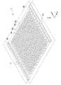
図1Aは本技術の一実施形態に係る原子層堆積(ALD:Atomic Layer Deposition)装置1の平面図である。図1Bは、図1Aに示したALD装置1の内部構造を示した模式図である。図2及び図3はALD装置1の断面図である。図2は図1AのA−A’線に沿った断面を示し、図3は図1AのB−B’線に沿った断面を示している。図1AではALD装置1の内部構造を透視して破線で示している。図1BではALD装置1の内部構造を模式的に示している。[Overall configuration of ALD apparatus 1]
FIG. 1A is a plan view of an atomic layer deposition (ALD)
ALD装置1は流路形成部材2を具備する。流路形成部材2はX軸方向及びY軸方向に延びる矩形の板状に形成されている。流路形成部材2は、その内部に前駆体ガスの流路が形成される部材である。 The
流路形成部材2は、前駆体ガスにより損傷を受けにくく、かつ、十分な耐熱性を有する固体材料で形成される。そのような材料としては、例えば、金属材料やセラミックス材料が挙げられる。樹脂材料は、ALD装置1が低温で用いられ、加熱により気体を発生させない条件の場合に、流路形成部材2を形成する材料として採用可能である。 The flow
流路形成部材2を形成する材料は、成膜物質や、流路内のクリーニング方法に応じて決定可能である。本実施形態では成膜物質がアルミナ(Al2O3)である場合について説明するため、流路形成部材2は、流路に付着したアルミナ膜を除去するときにダメージを受けにくいステンレスで形成されている。しかし、成膜物質がアルミナでない場合には、流路形成部材2を形成する材料として、例えば、ALD装置1の軽量化を図るためにアルミニウム(Al)を採用してもよい。The material forming the flow
流路形成部材2には、それぞれX軸方向に延びるガス供給用の供給路13及び排気用の排出路23がY軸方向に沿って交互に等間隔で設けられている。供給路13は図1A〜図3における流路形成部材2の左側の端部から右側の端部まで延びている。排出路23は図1A〜図3における流路形成部材2の右側の端部から左側の端部まで延びている。供給路13は流路形成部材2の右側の端部を貫通しておらず、排出路23は流路形成部材2の左側の端部を貫通していない。 In the flow
また、流路形成部材2には、供給路13からZ軸方向下方に延びる供給口14と、排出口23からZ軸方向下方に延びる排出口24とが設けられている。供給口14は、各供給路13におけるX軸方向に等間隔にある複数の位置から流路形成部材2のZ軸方向下面を貫通している。排出口24は、各排出路23におけるX軸方向に等間隔にある複数の位置から流路形成部材2のZ軸方向下面に貫通している。 Further, the flow
供給口14及び排出口24は、いずれも流路形成部材2の下面に配置されているが、基板Sの成膜面に対向していればよい。つまり、供給口14が形成される面と、排出口24が形成される面との間でZ軸方向の段差があってもよい。例えば、排出口24のZ軸方向下端が、供給口14のZ軸方向下端よりも、基板Sの成膜面から遠い位置にあってもよい。 Each of the
各供給路13は、供給口14より大径に形成されており、複数の供給口14とともにマニホールドを形成している。各排出路23は、排出口24より大径に形成されており、排出口24とともにマニホールドを形成している。また、各排出口24は供給口14よりもやや大径に形成されている。 Each
供給路13と複数の供給口14とがマニホールドを形成していることにより、供給路13におけるガスの圧力が一定に保たれるため、複数の供給口14は一定の圧力のガスを基板Sの成膜面に供給するようになる。また、排出路23と複数の排出口24とがマニホールドを形成していることにより、排出路23におけるガスの圧力が一定に保たれるため、複数の排出口24は一定の圧力でガスを排気するようになる。 Since the
各供給口13は、図3における部分拡大図に示すように、吐出角度θで基板Sの成膜面にガスを供給する。吐出角度θは、各供給口13から吐出されるガスの広がりを表しており、ガスの圧力などによって決定する。吐出角度θは、各供給口13が吐出するガスが基板Sの成膜面の全面に隙間なく供給されるように、ガスの圧力などにより調整可能である。 Each
供給路13、排出路23、供給口14、及び排出口24は、流路形成部材2にドリルを用いた切削加工を加えることにより形成されている。供給路13、排出路23、供給口14、及び排出口24の形成には、それらの径に応じた径のドリルビットが用いられる。 The
なお、本実施形態に係るALD装置1は、300mm×350mmのサイズの基板への成膜に対応するように構成されている。具体的には、ALD装置1では、供給路13が13本設けられ、各供給路13に供給口14がそれぞれ13本設けられている。また、ALD装置1では排出路23が13本設けられ、各排出路23に排出口24がそれぞれ13本設けられている。しかし、供給路13、供給口14、排出路23、及び排出口24の本数は適宜決定可能である。 Note that the
ALD装置1は接続部材5,6を具備する。接続部材5,6は、流路形成部材2のY軸方向の全幅にわたって延び、流路形成部材2のX軸方向の両端部に取り付けられている。接続部材5は、ガス供給源(不図示)と各供給路13とを接続するための部材である。接続部材6は、排気機構(不図示)と各排出路23とを接続するための部材である。この排気機構は、本実施形態ではポンプとして構成されるが、ガスを排出可能な構成を有していればよい。 The
接続部材5は、流路形成部材2における供給路13が開口したX軸方向左側の端部に取り付けられている。接続部材6は、流路形成部材2における排出路23が開口したX軸方向右側の端部に取り付けられている。接続部材5,6は、流路形成部材2と同様にステンレス材料で形成されている。しかし、接続部材5,6を形成する材料も、流路形成部材2と同様に、適宜変更可能である。 The connecting
接続部材5には、Y軸方向に延び、全ての供給路13を連通させる単一の供給室12と、供給室12をガス供給源に接続するための導入部11とが設けられている。供給室12は、供給路13より大径に形成されており、供給路13とともにマニホールドを形成している。 The
接続部材6には、Y軸方向に延び、全ての排出路23を連通させる単一の排出室22と、排出室22をポンプに接続するための排出部21とが設けられている。排出室22は、排出路23より大径に形成されており、排出路23とともにマニホールドを形成している。 The connecting
供給室12と複数の供給路13とがマニホールドを形成していることにより、供給室12におけるガスの圧力が一定に保たれるため、複数の供給路13におけるガスの圧力も一定に保たれている。また、排出室22と複数の排出路23とがマニホールドを形成していることにより、排出室22におけるガスの圧力が一定に保たれるため、複数の排出路23におけるガスの圧力も一定に保たれている。 Since the
導入部11及び供給室12は接続部材5にドリルやフライスなどを用いた切削加工を加えることにより形成されている。また、排出部21及び排出室22は接続部材6にドリルやフライスなどを用いた切削加工を加えることにより形成されている。 The
上記のように、導入部11、供給室12、供給路13、及び供給口14は相互に連通しており、ガス供給源に接続される供給機構を構成する。当該供給機構は、供給室12と供給路13とにより構成されるマニホールドと、供給路13と供給口14とにより構成されるサブマニホールドとを有する。つまり、供給機構は、マニホールドが2段階に組み合わせられた構成を有する。 As described above, the
また、排出部21、排出室22、排出路23、及び排出口24は相互に連通しており、ポンプに接続される排気機構を構成する。当該排気機構は、排出室22と排出路23とにより構成されるマニホールドと、排出路23と排出口24とにより構成されるサブマニホールドとを有する。つまり、排気機構は、マニホールドが2段階に組み合わせられた構成を有する。 Moreover, the
ALD装置1は保持部材3を具備する。保持部材3は、流路形成部材2のX軸方向及びY軸方向の全幅にわたって延びている。保持部材3は、流路形成部材2のZ軸方向下面を覆うように、その周縁部が全周にわたって流路形成部材2に結合されている。保持部材3は流路形成部材2との間に成膜室4を形成するための部材である。保持部材3は、流路形成部材2と同様にステンレス材料で形成されている。しかし、保持部材3を形成する材料も、流路形成部材2と同様に、適宜変更可能である。 The
保持部材3は、流路形成部材2に結合される周縁部に囲まれ、供給口14及び排出口24に対向する面であるステージ3aを有する。ステージ3aは、保持部材3のZ軸方向上面を切削することにより流路形成部材2のZ軸方向下面に平行に形成されている。つまり、ステージ3aは、保持部材3の周縁部におけるZ軸方向上面からZ軸方向下方に窪んだ位置にある。 The holding
保持部材3は、ステージ3aと流路形成部材2のZ軸方向下面との間に成膜室4を形成する。成膜室4は、供給口14及び排出口24以外が流路形成部材2及び保持部材3によって閉じられた空間である。ステージ3aは基板Sを保持する保持部として構成される。 The holding
基板Sは、成膜面とは反対の面がステージ3aに対面し、成膜面が流路形成部材2に対向するように設置される。したがって、ステージ3aに設置された基板Sの成膜面は流路形成部材2の供給口14及び排出口24側に露出する。 The substrate S is placed so that the surface opposite to the film formation surface faces the
成膜室4内のステージ3a上に基板Sの設置は、手作業による方法でもロボットなどによって自動で行なう方法でもよい。また、ALD装置1は、基板Sを収容したカセットなどを、カセットごと成膜室4内に設置可能な構成であってもよい。 The substrate S may be placed on the
図1Aに示すように、ALD装置1の供給口14及び排出口24の位置は、ステージ3aに設置された基板Sの成膜面の全面にわたって均等に割り当てられている。これにより、ALD装置1では、基板Sの成膜面の全面にわたって同一の条件で薄膜の形成を行なうことができる。 As shown in FIG. 1A, the positions of the
本実施形態における基板Sはガラス基板であるが、基板の種類は制限されない。ALD成膜装置1で成膜可能な基板としては、例えば、一般的な、各種セラミックス基板やシリコン基板や樹脂基板や有機フィルム基板が挙げられる。また、ALD成膜装置1は、例えば、アルミニウムや銅などにより形成された金属基板や、複数の種類の材料が組み合わされて構成された複合基板にも成膜可能である。 The substrate S in this embodiment is a glass substrate, but the type of substrate is not limited. Examples of the substrate that can be formed by the ALD
[ALD装置1による成膜方法]
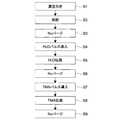
図4はALD装置1による成膜方法を示すフローチャートである。本実施形態に係る成膜方法について、図4に示したフローチャートに沿って、図1A〜3を参照しながら説明する。具体的には、基板Sがステージ3a上に設置された状態で、図4に示したステップS1〜S9が行われる。[Film Forming Method Using ALD Apparatus 1]
FIG. 4 is a flowchart showing a film forming method by the
ステップS1では、排出部21に接続されたポンプによって成膜室4内の真空引きが行なわれる。このとき導入部11側に設けられた弁(不図示)は閉状態とされ、ALD装置1内は密閉状態とされる。これにより、成膜室4を含めたALD装置1内の空間全体が真空状態となる。このステップS1における成膜室4の真空度は高いことが望ましい。 In step S <b> 1, the film formation chamber 4 is evacuated by a pump connected to the
具体的には、ALD装置1内の空気が、排出口24、排出路23、排出室22及び排出部21の排出機構を通ってALD装置1の外に排出される。更に、詳細は後述するが、ポンプは導入口11にも接続されており、ALD装置1内の空気は、供給口14、供給路13、供給室12及び供給部11の供給機構によってもALD装置1の外に排出される。 Specifically, the air in the
この構成により、ALD装置1内の排気時間が短縮される。これにより、ステップS1が短縮され、ステップS1以降の排気を伴うステップも短縮可能である。 With this configuration, the exhaust time in the
ステップS2では、ALD装置1全体の加熱が行なわれる。ALD装置1の加熱温度は、前駆体ガスの反応温度や基板Sの成膜面の耐熱温度などに応じて設定される。本実施形態では、前駆体ガスとしてトリメチルアルミニウム(TMA:Trimethylaluminium)及びH2O(水蒸気)を用い、ALD装置1の加熱温度は50℃以上320℃以下の範囲内で設定される。なお、前駆体ガスが異なる場合には、ALD装置1の加熱温度は適宜変更可能である。In step S2, the
ステップS3では、成膜室4内のN2パージが行なわれる。ステップS3では、ステップS1で真空引きした成膜室4内に不活性ガスであるN2を導入し、再度成膜室4内を真空引きする。これにより、ステップS1後に成膜室4内に残存しているガスがN2によって置換されて、成膜室4の外に排出される。ステップ3により、ステップS1後に残存しているガスの影響を排除することができる。In step S3, N2 purge in the film forming chamber 4 is performed. In step S3, N2 that is an inert gas is introduced into the film forming chamber 4 evacuated in step S1, and the film forming chamber 4 is evacuated again. As a result, the gas remaining in the film forming chamber 4 after step S1 is replaced by N2 and discharged out of the film forming chamber 4. By
具体的には、N2は、供給部11、供給室12、供給路13及び供給口14の供給機構を通って成膜室4内に導入される。また、成膜室4内のN2は、上記の排気機構24,23,22,21及び供給機構14,13,12,11によってALD装置1の外に排出される。Specifically, N2 is introduced into the film formation chamber 4 through the supply mechanism of the
ステップS4では、H2Oが成膜室4内にパルス導入される。具体的には、導入部11からH2Oが所定時間導入されることにより、H2Oが供給口14から基板Sの成膜面に向けて吐出される。このとき、排出部21側に設けられた弁(不図示)は閉状態とされ、成膜室4の排気は行われていない。H2Oのパルス導入の時間及び回数は基板Sの成膜面の面積によって決定可能である。また、N2の導入量は、例えば、N2の流量が30〜200sccmで、成膜室4内の気圧が4×10⁻¹torr(5.33×10Pa)程度となる条件で決定可能である。In step S 4, H2 O is pulsed into the film forming chamber 4. Specifically, H2 O is discharged from the
H2Oは、上記の供給機構11、12,13,14を通って成膜室4内に導入される。より詳細には、供給部11に導入されたH2Oは、供給室12内で拡散され、供給室12で一定の圧力となる。そして、H2Oは、供給室12から各供給路13に一定の圧力で導入され、供給路13内で拡散され、供給路13内で一定の圧力となる。そして、H2Oは、供給路13から各供給口14に一定の圧力で導入される。したがって、H2Oは、全ての供給口14から一定の圧力で吐出される。H2 O is introduced into the film forming chamber 4 through the
このように、本実施形態では、全ての供給口14から一定の吐出圧で基板Sの成膜面に向けてH2Oが供給される。そのため、基板Sの成膜面におけるH2Oの濃度分布が発生しにくい。Thus, in this embodiment, H2 O is supplied from all the
ステップS5では、成膜室4内に導入されたH2Oが成膜室4全体に拡散させられる。具体的には、ステップS4の後に、導入部11側に設けられた弁が閉じられ、この状態が保持される。これにより、H2Oが成膜室4内にける濃度が均一になる。つまり、ステップS5によって、基板Sの成膜面の全面にわたってH2Oの供給条件が一定となる。In step S <b > 5, H2 O introduced into the film formation chamber 4 is diffused throughout the film formation chamber 4. Specifically, after step S4, the valve provided on the
本実施形態では、ステップS4において、基板Sの成膜面におけるH2Oの濃度分布が発生しにくいため、ステップS5の時間が大幅に短縮される。更に、基板Sの成膜面に形成する薄膜に求められる均一性に応じ、ステップS4においてH2Oの濃度が十分に均一である場合には、ステップS5を省略することも可能である。In this embodiment, since the H2 O concentration distribution on the film formation surface of the substrate S hardly occurs in step S4, the time of step S5 is greatly shortened. Furthermore, if the concentration of H2 O is sufficiently uniform in step S4 according to the uniformity required for the thin film formed on the film formation surface of the substrate S, step S5 can be omitted.
ステップS6では、成膜室4内のN2パージが行なわれる。ステップS6では、成膜室4内を真空引きし、成膜室4内に不活性ガスであるN2を導入し、再度成膜室4内を真空引きする。これにより、成膜室4からH2Oが排出される。In step S6, N2 purge in the film forming chamber 4 is performed. In step S6, the inside of the film forming chamber 4 is evacuated, N2 that is an inert gas is introduced into the film forming chamber 4, and the inside of the film forming chamber 4 is evacuated again. Thereby, H2 O is discharged from the film forming chamber 4.
ステップS7では、TMAが成膜室4内にパルス導入される。具体的には、導入部11からTMAが所定時間導入されることにより、TMAが供給口14から基板Sの成膜面に向けて吐出される。このとき、排出部21側に設けられた弁(不図示)は閉状態とされ、成膜室4の排気は行われていない。TMAのパルス導入の時間及び回数は基板Sの成膜面の面積によって決定可能である。また、N2の導入量は、例えば、N2の流量が30〜200sccmで、成膜室4内の気圧が4×10⁻¹torr(5.33×10Pa)程度となる条件で決定可能である。N2の流量は、例えば、TMAのパルス導入の時間や、成膜室4の容積によって決定可能である。In step S 7, TMA is pulsed into the film forming chamber 4. Specifically, TMA is discharged from the
TMAは、上記の供給機構11、12,13,14を通って成膜室4内に導入される。より詳細には、供給部11に導入されたTMAは、供給室12内で拡散され、供給室12で一定の圧力となる。そして、TMAは、供給室12から各供給路13に一定の圧力で導入され、供給路13内で拡散され、供給路13内で一定の圧力となる。そして、TMAは、供給路13から各供給口14に一定の圧力で導入される。したがって、TMAは、全ての供給口14から一定の圧力で吐出される。 TMA is introduced into the film forming chamber 4 through the
このように、本実施形態では、全ての供給口14から一定の吐出圧で基板Sの成膜面に向けてTMAが供給される。これにより、基板Sの成膜面におけるTMAの濃度分布が発生しにくい。 Thus, in the present embodiment, TMA is supplied from all the
ステップS8では、成膜室4内に導入されたTMAが成膜室4全体に拡散させられる。具体的には、ステップS7の後に、導入部11側に設けられた弁が閉じられ、この状態が保持される。これにより、TMAが成膜室4内にける濃度が均一になる。つまり、ステップS8によって、基板Sの成膜面の全面にわたってTMAの供給条件が一定となる。 In step S <b> 8, TMA introduced into the film formation chamber 4 is diffused throughout the film formation chamber 4. Specifically, after step S7, the valve provided on the
本実施形態では、ステップS7において、基板Sの成膜面におけるTMAの濃度分布が発生しにくいため、ステップS8の時間が大幅に短縮される。更に、基板Sの成膜面に形成する薄膜に求められる均一性に応じ、ステップS7においてTMAの濃度が十分に均一である場合には、ステップS8を省略することも可能である。 In the present embodiment, since the TMA concentration distribution on the film formation surface of the substrate S hardly occurs in step S7, the time of step S8 is greatly shortened. Furthermore, if the TMA concentration is sufficiently uniform in step S7 according to the uniformity required for the thin film formed on the film formation surface of the substrate S, step S8 can be omitted.
ステップS9では、成膜室4内のN2パージが行なわれる。ステップS9では、成膜室4内を真空引きし、成膜室4内に不活性ガスであるN2を導入し、再度成膜室4内を真空引きする。これにより、成膜室4からTMAが排出される。In step S9, N2 purge in the film forming chamber 4 is performed. In step S9, the inside of the film forming chamber 4 is evacuated, N2 that is an inert gas is introduced into the film forming chamber 4, and the inside of the film forming chamber 4 is again evacuated. Thereby, TMA is discharged from the film forming chamber 4.
ALD装置1は、ステップS4〜S9を1サイクルとして、基板Sの成膜面に化学量論組成(Al2O3)近傍のアルミナの1分子層分の層が形成されるように構成されている。したがって、ステップ9の後にステップS4〜S9を再度行なうことにより、基板Sの成膜面に2粒子分のアルミナの層が形成される。ALD装置1を用いた成膜方法では、基板Sの成膜面に形成する薄膜の厚さに応じて、ステップS4〜S9が繰り返される。このように、ALD装置1は、分子単位で薄膜の膜厚を制御することができるため、薄膜の膜厚の制御性に優れる。The
そして、ALD装置1では、ステップS4〜S9が所定回数繰り返された後に、成膜室4内が大気圧にされ、各基板Sが取り出される。 In the
ALD装置1は、液晶表示パネルや有機EL(Electro Luminescence)パネル用TFT(Thin Film Transistor)の層間絶縁膜や有機EL用の水蒸気バリア膜の形成に適している。ALD装置1では、例えば、300mm×350mmの基板Sに、膜厚の誤差範囲が3%以内であり、密度が2.9g/cm3以上であり、屈折率が1.6以上であるアルミナ薄膜を形成することができた。このアルミナ薄膜では充分な絶縁性や水蒸気バリア性が得られた。The
なお、本実施形態に係るALD装置1では、2種類の前駆体ガスに対して1つの供給機構11、12,13,14を用いたが、前駆体ガスの種類に応じて供給機構を変更することが好ましい。これは、2種類の前駆体ガスが1つの供給機構を交互に通ると、供給機構内に前駆体ガスがわずかに残存している前駆体ガス同士がクロストークすることがあるためである。 In the
供給機構内で前駆体ガス同士がクロストークすると、前駆体ガスが気相反応したり、前駆体ガスが供給機構内に析出したりすることがある。前駆体ガスが気相反応すると、気相反応した分の前駆体ガスが消耗してしまう。また、前駆体ガスが供給機構内に析出すると、供給機構の容積の変化が生じるとともに、供給口14が析出物によって閉塞される場合がある。 When the precursor gases cross-talk within the supply mechanism, the precursor gas may undergo a gas phase reaction, or the precursor gas may precipitate in the supply mechanism. When the precursor gas undergoes a gas phase reaction, the precursor gas corresponding to the gas phase reaction is consumed. Further, when the precursor gas is precipitated in the supply mechanism, the
図5は、ALD装置1の変形例に係る供給機構及び排気機構の概略を示す説明図である。このALD装置は、第1の前駆体ガスAを供給する第1の供給機構(実線で示す。)と、第2の前駆体ガスBを供給する第2の供給機構(一点鎖線で示す。)とを具備する。なお、このALD装置でも、排気機構(破線で示す。)は1つである。このALD装置では、ガスA及びガスBについてそれぞれ供給機構が設けられているため、供給機構内におけるガスAとガスBとのクロストークは生じない。 FIG. 5 is an explanatory diagram showing an outline of a supply mechanism and an exhaust mechanism according to a modification of the
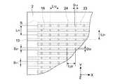
[ALD装置1の各部の寸法]
図6はALD装置1の供給機構及び排気機構の寸法を例示した平面図である。本例は、排気能力100〜1000l/minのポンプを用いることを前提として設計している。供給口14のY軸方向の間隔L11及び排出口24のY軸方向の間隔L21はいずれも22mmである。供給口14のX軸方向の間隔L12及び排出口24のX軸方向の間隔L22はいずれも20mmである。供給路13の径D11及び排出路23の径D21はいずれも5mmである。供給口14の径D12は2mmで、排出口24の径D22は4mmである。[Dimensions of each part of ALD apparatus 1]
FIG. 6 is a plan view illustrating dimensions of the supply mechanism and the exhaust mechanism of the
また、供給口14と基板Sの成膜面との間の距離は、供給口14の間隔L11,L12と同等以下とすることができる。供給口14と基板Sの成膜面との間の距離が小さいほど、成膜室4の容積が小さくなるため、成膜室4の排気の時間を短縮することが可能である。ALD装置1では、供給口14と基板Sの成膜面との間の距離は7mmであり、1mmまで小さくすることに成功している。Further, the distance between the
一方で、供給口14におけるガスの吐出角度θ(図3参照)が一定であるものと仮定すると、ガスが基板Sの成膜面の全面に隙間なく供給されるためには、供給口14と基板Sの成膜面との間の距離が小さいほど、供給口14の間隔L11,L12を小さくする必要がある。供給口14の間隔L11,L12を小さくするためには、流路形成部材2の加工のためのコストが高くなる。以上により、供給口14と基板Sの成膜面との間の距離は2mm程度までであることが現実的である。On the other hand, assuming that the gas discharge angle θ (see FIG. 3) at the
また、供給口14の間隔L11,L12は小さいほど好ましいが、供給口14の間隔L11,L12は小さくすると、供給口14の径D11を大きくする必要がある。そのため、L11,L12,D11の値は、これらの影響が総合的に考慮されることにより決定されることが好ましい。Further, although the intervals L11 and L12 between the
排出口24の径D22は、排出路23の径D21や排出口24の間隔L21,L22による制限があるものの、大きいほど好ましい。これは、成膜室4内の排気時のコンダクタンスを大きくすることができるとともに、成膜室4内をより均一に排気することができるようになるためである。DiameterD 22 of the
図7はALD装置1の変形例に係る供給機構及び排気機構の寸法を例示した平面図である。この供給機構及び排気機構は、コストダウン設計がなされている。具体的には、本例は、ガス供給及び排気の効率を向上させることにより、排気能力100〜1000l/minのポンプを用いることを前提として設計している。 FIG. 7 is a plan view illustrating dimensions of a supply mechanism and an exhaust mechanism according to a modification of the
図7に示すように、供給口14及び排出口24の間隔が広く、隣接する4つの供給口14の対角線上に排出口24が配置され、隣接する4つの排出口24の対角線上に供給口14が配置されている。供給口14のY軸方向の間隔L11及び排出口24のY軸方向の間隔L21はいずれも30mmである。供給口14のX軸方向の間隔L12及び排出口24のX軸方向の間隔L22はいずれも30mmである。供給路13の径D11及び排出路23の径D21はいずれも8mmである。供給口14の径D12は3mmで、排出口24の径D22は6mmである。As shown in FIG. 7, the interval between the
[積層ALD装置100]
図8は本実施形態に係る積層ALD装置100の断面図である。積層ALD装置100は、ALD装置1を1ユニットとして5ユニットZ軸方向に積層されている。ALDユニット1は、ALD装置1と同様の構成であるため、その説明を省略する。各ALDユニットの導入部11に対して並列にガス供給源が接続され、排出部21に対して並列にポンプが接続される。これにより、積層ALD装置100では、5枚の基板Sの成膜面に同時に成膜することができる。[Laminated ALD apparatus 100]
FIG. 8 is a cross-sectional view of the
なお、量産を目的とした構造を有するALD装置では、一般的に、設置する基板の枚数によって成膜条件が変化する。しかし、積層ALD装置100では、全てのALDユニット1に基板Sを設置する必要はない。積層ALD装置100は、例えば1つのALDユニット1のみに基板Sを設置される場合にも、全てのALDユニット1に基板Sを設置する場合と同様の条件で成膜可能な構成を有する。 Note that in an ALD apparatus having a structure for mass production, generally, the film formation conditions vary depending on the number of substrates to be installed. However, in the
また、積層ALD装置は、ALDユニットの積層数は、適宜変更可能である。例えば、積層ALD装置は、10個のALDユニットが積層された構成を有していてもよい。この場合、積層ALD装置は、最大で10枚の基板Sの成膜面に同時に成膜できるようになる。 In the stacked ALD apparatus, the number of stacked ALD units can be changed as appropriate. For example, the stacked ALD apparatus may have a configuration in which 10 ALD units are stacked. In this case, the stacked ALD apparatus can simultaneously form a film on the film formation surfaces of 10 substrates S at the maximum.
[積層ALD装置100のガス供給系及び排気系]
図9は積層ALD装置100のガス供給系及び排気系を示した模式図である。なお、ここでは積層ALD装置100について説明するが、上記のALD装置1は、積層ALD装置100のALDユニット1が1つのみの場合であるので、同様の説明が適用される。[Gas supply system and exhaust system of stacked ALD apparatus 100]
FIG. 9 is a schematic diagram showing a gas supply system and an exhaust system of the
第1のガス供給源であるH2O供給源は、ALDバルブとバルブV2を介して積層ALD装置100の各導入部11に接続されている。H2O用ALDバルブには、マスフローコントローラ(MFC)を介してN2供給源が接続されている。これにより、H2Oが、ALDバルブによって流量を精密に制御されながら積層ALD装置100の導入部11に供給されることが可能となる。An H2 O supply source that is a first gas supply source is connected to each
第2のガス供給源であるTMA供給源は、ALDバルブとバルブV1を介して積層ALD装置100の各導入部11に接続されている。TMA用ALDバルブには、マスフローコントローラ(MFC)を介してN2供給源が接続されている。これにより、TMAが、ALDバルブによって流量を精密に制御されながら積層ALD装置100の導入部11に供給されることが可能となる。A TMA supply source that is a second gas supply source is connected to each
ポンプとしては、一般的な真空ポンプが使用される。真空ポンプの種類やその組み合わせは適宜決定可能である。本実施形態では、真空ポンプがドライポンプとして構成される。ドライポンプは、単独で用いられても、多段で用いられてもよい。ドライポンプが多段で用いられる場合、メインポンプとしては、例えば、メカニカルブースターポンプ(MBP)やターボ分子ポンプが挙げられ、メインポンプを補助する補助ポンプとしては、例えば、ルーツポンプやスクロールポンプやスクリューポンプが挙げられる。なお、ドライポンプ以外の真空ポンプも採用可能であり、そのような真空ポンプとしては、例えば、ロータリーポンプが挙げられる。 A general vacuum pump is used as the pump. The type and combination of vacuum pumps can be determined as appropriate. In this embodiment, the vacuum pump is configured as a dry pump. The dry pump may be used alone or in multiple stages. When the dry pump is used in multiple stages, examples of the main pump include a mechanical booster pump (MBP) and a turbo molecular pump. Examples of the auxiliary pump that assists the main pump include a roots pump, a scroll pump, and a screw pump. Is mentioned. A vacuum pump other than the dry pump can also be used, and an example of such a vacuum pump is a rotary pump.
また、ポンプは、バルブV4、トラップ、バルブV6、及びバルブV2を介して積層ALD装置100の導入部11に接続されている。また、ポンプは、バルブV4、トラップ、バルブV5、及びバルブV1を介して積層ALD装置100の導入部11に接続されている。排気系には、積層ALD装置100内の圧力をモニタリングするための真空ゲージG1が設けられていてもよい。 Further, the pump is connected to the
バルブV4、トラップ、バルブV6、及びバルブV2はポンプと導入部11とを接続する第1のバイパス路を構成し、バルブV4、トラップ、バルブV5、及びバルブV1はポンプと導入部11とを接続する第2のバイパス路を構成している。これにより、積層ALD装置100では、排出部21のみならず導入部11を介して供給機構及び排気機構の排気を行なうことができる。これにより、積層ALD装置100における排気時間が短縮する。 The valve V4, the trap, the valve V6, and the valve V2 constitute a first bypass path that connects the pump and the
具体的に、120℃の処理温度で10枚の基板Sの成膜面に50nmの膜厚の薄膜を形成してみた。本実施形態に係る積層ALD装置としては、10個のALDユニット1が積層された積層ALD装置を用いた。一般的な積層ALD装置では、良好な絶縁性を得るための処理時間が15.5時間であったのに対し、本実施形態に係る積層ALD装置では、良好な絶縁性を得るための処理時間が1.4時間であった。このように、本実施形態に係る積層ALD装置では、排気時間を短縮することにより、処理時間を大幅に短縮することができた。また、本実施形態に係る積層ALD装置では基板Sの成膜面に形成された薄膜の膜厚の均一性が改善された。薄膜の膜厚の均一性は、目的とする膜厚(本実施形態では50nmである)に対する誤差が、目的とする膜厚に対して何%以内に収まっているかという指標で評価した。具体的には、一般的な積層ALD装置では均一性が3%程度であったのに対し、本実施形態に係るALD装置100では均一性が1%程度まで改善した。 Specifically, a thin film having a thickness of 50 nm was formed on the deposition surfaces of ten substrates S at a processing temperature of 120 ° C. As the stacked ALD apparatus according to this embodiment, a stacked ALD apparatus in which 10
図10は本実施形態の比較例に係る積層ALD装置500のガス供給系及び排気系を示した模式図である。積層ALD装置500は、真空チャンバー内に複数段の棚501が配置された構造を有する。積層ALD装置500では、ガス供給と排気とがそれぞれ1ヶ所から行われる。 FIG. 10 is a schematic diagram showing a gas supply system and an exhaust system of a
つまり、積層ALD装置500では、前駆体ガスがその中で拡散されることにより、当該前駆体ガスが各棚501に設置された基板Sの成膜面に供給される。そして、積層ALD装置500では、前駆体ガスが所定時間拡散された後に排気される。積層ALD装置500では、このガス供給及び排気を繰り返すことにより、各棚501に配置された基板Sの成膜面に薄膜を形成する。 That is, in the
積層ALD装置500では、第1のガス供給源であるH2O供給源及び第2のガス供給源であるTMA供給源は、ALDバルブを介して積層ALD装置500に接続されている。N2供給源もMFC介して積層ALD装置500に接続されている。これにより、H2O、TMA及びN2が、ALDバルブによって流量を精密に制御されながら積層ALD装置500に供給されることが可能となる。In the
ポンプは、バルブV15、及びトラップを介して積層ALD装置500に接続されている。これにより、積層ALD装置500では、ポンプを用いて排気可能となる。 The pump is connected to the
なお、比較例に係る積層ALD装置500では、ガス供給が1ヶ所から行われるため、前駆体ガスの濃度分布が生じ、前駆体ガスが複数の基板Sの各成膜面に均一に供給されない場合がある。また、積層ALD装置500では、排気が1ヶ所から行なうことも、前駆体ガスの濃度分布が発生する原因となる。一方、本実施形態に係る積層ALD装置100では、各基板Sごとに成膜室が分かれており、かつ、各基板Sの成膜面に対向する供給口から前駆体ガスが供給されるため、前駆体ガスがいずれの基板Sの成膜面にも均一に供給される。 Note that, in the
また、比較例に係る積層ALD装置500は、本実施形態に係る積層ALD装置100よりも容積が大きい。そのため、比較例に係る積層ALD装置500では、本実施形態に係る積層ALD装置100よりも短時間での排気が可能である。 Further, the
また、ALD装置500は、流路を有さないため、排気時のコンダクタンスが大きい。一方で、本実施形態に係るALD装置100は、流路が形成された構成を有するため、ALD装置500に比べると排気時のコンダクタンスが小さい。しかし、上述したように、積層ALD装置100は、排出部21のみならず導入部11を介して供給機構及び排気機構の排気を行なうため、排気時のコンダクタンスが充分に増大されている。したがって、積層ALD装置100では短時間での排気が可能である。 Moreover, since the
[変形例]
図11は、本実施形態に係る積層ALD装置100の変形例に係る積層ALD装置の模式図である。この積層ALD装置は、いわゆるリモートプラズマ方式を採用し、積層ALD装置100に高周波プラズマユニット110が付加されて構成されている。高周波プラズマユニット110は、積層ALD装置100の導入部11に隣接して設けられ、導入部11に導入される前のH2O及びTMAに高周波電圧を印加してプラズマを発生させ、H2O及びTMAをプラズマにより活性化させる。この積層ALD装置では、プラズマにより活性化したH2O及びTMAが各基板Sの成膜面に供給されることにより、H2O及びTMA同士の反応が活性化される。[Modification]
FIG. 11 is a schematic diagram of a stacked ALD apparatus according to a modification of the
図12は、本実施形態に係る積層ALD装置100の変形例に係る積層ALD装置200の模式図である。このALD装置200は、いわゆるダイレクトプラズマ方式を採用し、成膜室4において前駆体ガスのプラズマを発生させることが可能な構成を有している。各ALDユニット1は、流路形成部材2がアノード(第1の電極)として機能し、保持部材3がカソード(第2の電極)として機能するように構成されている。流路形成部材2及び保持部材3はそれぞれ電源(不図示)に接続されている。そして、積層ALD装置200は、各ALDユニット1の間に絶縁層7を有している。絶縁層7は、Z軸方向に隣接するALDユニット1のうち、上側のALDユニット1の保持部材3と、下側のALDユニット1の流路形成部材2とを絶縁している。積層ALD装置200では、各ALDユニット1において流路形成部材2と保持部材3との間に高周波電圧を印加することにより、成膜室4内でプラズマを発生させる。 FIG. 12 is a schematic diagram of a
以上、本発明の実施形態について説明したが、本発明は上述の実施形態にのみ限定されるものではなく、本発明の要旨を逸脱しない範囲内において種々変更を加え得ることは勿論である。 The embodiment of the present invention has been described above, but the present invention is not limited to the above-described embodiment, and it is needless to say that various modifications can be made without departing from the gist of the present invention.
例えば、上記実施形態では、ALD装置によって基板Sの成膜面にアルミナを形成する場合について説明した。しかし、本実施形態に係るALD装置では、多種多様な薄膜を形成することが可能である。そのような薄膜としては、例えば、各種酸化物膜、各種窒化物膜、各種金属膜、各種硫化物膜、及び各種フッ化物膜が挙げられる。 For example, in the above embodiment, the case where alumina is formed on the film formation surface of the substrate S by the ALD apparatus has been described. However, the ALD apparatus according to the present embodiment can form a wide variety of thin films. Examples of such a thin film include various oxide films, various nitride films, various metal films, various sulfide films, and various fluoride films.
酸化物膜としては、例えば、TiO2、TaO5、Nb2O5、ZrO2、HfO2、SnO2、ZnO、SiO2、InO3が挙げられる。窒化物膜としては、例えば、AlN、TaNX、TiN、MoN、ZrN、HfN、GaNが挙げられる。金属膜としては、例えば、Pt、Pd、Cu、Fe、Co、Niが挙げられる。硫化物膜としては、例えば、ZnS、SrS、CaS、PbSが挙げられる。フッ化物膜としては、例えば、CaF2、SrF2、ZnF2が挙げられる。Examples of the oxide film include TiO2 , TaO5 , Nb2 O5 , ZrO2 , HfO2 , SnO2 , ZnO, SiO2 , and InO3 . Examples of the nitride film include AlN, TaNx , TiN, MoN, ZrN, HfN, and GaN. Examples of the metal film include Pt, Pd, Cu, Fe, Co, and Ni. Examples of the sulfide film include ZnS, SrS, CaS, and PbS. Examples of the fluoride film include CaF2 , SrF2 , and ZnF2 .
また、供給口及び排出口のXY平面における形状は円形に限らない。供給口及び排出口の形状は、例えば、楕円形や多角形でもよい。更に、供給口及び排出口は、スリット状であってもよい。この場合スリットの形状は、直線や円弧とすることができ、更に複雑に屈曲していてもよい。 Further, the shape of the supply port and the discharge port in the XY plane is not limited to a circle. The shape of the supply port and the discharge port may be, for example, an ellipse or a polygon. Further, the supply port and the discharge port may be slit-shaped. In this case, the shape of the slit can be a straight line or an arc, and may be bent more complicatedly.
更に、ALD装置は、供給口及び排出口が基板Sの成膜面に対向していればよく、本実施形態に係る供給機構及び排気機構を備えていなくてもよい。供給口及び排出口は、例えば、いわゆるシャワーヘッドとして構成されていてもよい。この場合、シャワーヘッドが基板Sの成膜面に対向し、シャワーヘッドの各開口がそれぞれ供給口及び排出口のうちのいずれか一方として構成される。 Furthermore, the ALD apparatus only needs to have the supply port and the discharge port facing the film formation surface of the substrate S, and may not include the supply mechanism and the exhaust mechanism according to the present embodiment. The supply port and the discharge port may be configured as so-called shower heads, for example. In this case, the shower head faces the film formation surface of the substrate S, and each opening of the shower head is configured as one of a supply port and a discharge port.
なお、本技術は以下のような構成も採ることができる。
(1)
密閉可能な成膜室と、
成膜面を有する基板を上記成膜室内に保持する保持部と、
ガスを供給するガス供給源に接続される導入部を有し、上記導入部に導入されたガスを、上記成膜面に対向する位置から上記成膜室に供給する供給機構と、
ポンプに接続される排出部を有し、上記成膜面に対向する位置から、上記成膜室を排気する排気機構と
を具備する原子層堆積装置。
(2)
上記(1)に記載の原子層堆積装置であって、
上記供給機構は、上記導入部に接続され、上記成膜面に対向する供給口を更に有し、
上記排気機構は、上記排出部に接続され、上記成膜面に対向する排出口を更に有する
原子層堆積装置。
(3)
上記(2)に記載の原子層堆積装置であって、
上記供給口と上記排出口とが隣接している
原子層堆積装置。
(4)
上記(2)又は(3)に記載の原子層堆積装置であって、
上記供給機構は、複数の供給口と、上記複数の供給口を上記導入部に接続し、上記複数の供給口とともにマニホールドを形成する供給路とを更に有し、
上記排気機構は、複数の排出口と、上記複数の排出口を上記排出部に接続し、上記複数の排出口とともにマニホールドを形成する排出路とを更に有する
原子層堆積装置。
(5)
上記(4)に記載の原子層堆積装置であって、
上記供給路、上記供給口、上記排出路、及び上記排出口がいずれも同一部材に形成されている
原子層堆積装置。
(6)
上記(4)又は上記(5)に記載の原子層堆積装置であって、
複数の供給機構を具備し、
上記複数の供給機構がそれぞれ異なる種類のガスを上記成膜室に供給する
原子層堆積装置。
(7)
上記(4)から(6)のいずれか1つに記載の原子層堆積装置であって、
上記供給機構は、複数の供給路と、上記複数の供給路を上記導入部に接続し、上記供給路とともにマニホールドを形成する導入室とを更に有し、
上記排気機構は、複数の排出路と、上記複数の排出路を上記排出部に接続し、上記供給路とともにマニホールドを形成する排出室を更に有する
原子層堆積装置。
(8)
上記(7)に記載の原子層堆積装置であって、
上記複数の供給路と上記複数の排出路とが交互に配列されている
原子層堆積装置。
(9)
上記(1)から(8)のいずれか1つに記載の原子層堆積装置であって、
上記ポンプと上記導入部とを接続するバイパス路を更に具備する
原子層堆積装置。
(10)
上記(1)から(9)のいずれか1つに記載の原子層堆積装置であって、
前記ガス供給源と前記導入部との間に配置され、前記導入部に導入されるガスのプラズマを発生させるプラズマユニットを更に具備する
原子層堆積装置。
(11)
上記(1)から(10)のいずれか1つに記載の原子層堆積装置であって、
前記成膜室内に設けられ、電源に接続されて前記成膜室内のガスのプラズマを発生させる1対の電極を更に具備する
原子層堆積装置。
(12)
上記(11)に記載の原子層堆積装置であって、
前記導入機構と前記供給機構とがいずれも単一の流路形成部材に形成され、
前記保持部及び前記流路形成部材が前記1対の電極を構成する
原子層堆積装置。
(13)
上記(1)から(12)のいずれか1つに記載の原子層堆積装置であって、
上記成膜室、上記保持部、上記供給機構、及び上記排気機構を有する複数の原子層堆積ユニットを具備する
原子層堆積装置。
(14)
上記(13)に記載の原子層堆積装置であって、
上記複数の原子層堆積ユニットが上記成膜面に垂直な方向に積層されている
原子層堆積装置。
(15)
基板の成膜面に対向する第1の位置からガスを供給し、
上記成膜面に対向する第2の位置から排気する
原子層堆積方法。
(16)
上記(15)に記載の原子層堆積方法であって、
上記第1の位置と上記第2の位置とが隣接している
原子層堆積方法。
(17)
上記(15)又は(16)に記載の原子層堆積方法であって、
複数の第1の位置からガスを供給し、
複数の第2の位置から排気する
原子層堆積方法。
(18)
上記(15)から(17)のいずれか1つに記載の原子層堆積方法であって、
プラズマ化により活性化したガスを前記第1の位置から供給する
原子層堆積方法。
(19)
上記(18)に記載の原子層堆積方法であって、
前記成膜面と、前記成膜面に対向する面との間に電圧を印加することにより、前記第1の位置から供給されたガスのプラズマを発生させる
原子層堆積方法。In addition, this technique can also take the following structures.
(1)
A film forming chamber that can be sealed;
A holding unit for holding a substrate having a film formation surface in the film formation chamber;
A supply mechanism that has an introduction part connected to a gas supply source for supplying gas, and that supplies the gas introduced into the introduction part to the film formation chamber from a position facing the film formation surface;
An atomic layer deposition apparatus comprising: a discharge unit connected to a pump, and an exhaust mechanism that exhausts the film formation chamber from a position facing the film formation surface.
(2)
The atomic layer deposition apparatus according to (1) above,
The supply mechanism further includes a supply port connected to the introduction portion and facing the film formation surface,
The atomic layer deposition apparatus, wherein the exhaust mechanism further includes a discharge port connected to the discharge unit and facing the film formation surface.
(3)
The atomic layer deposition apparatus according to (2) above,
An atomic layer deposition apparatus in which the supply port and the discharge port are adjacent to each other.
(4)
The atomic layer deposition apparatus according to (2) or (3) above,
The supply mechanism further includes a plurality of supply ports, and a supply path that connects the plurality of supply ports to the introduction portion and forms a manifold together with the plurality of supply ports,
The atomic layer deposition apparatus, wherein the exhaust mechanism further includes a plurality of discharge ports, and a discharge path that connects the plurality of discharge ports to the discharge unit and forms a manifold together with the plurality of discharge ports.
(5)
The atomic layer deposition apparatus according to (4) above,
The atomic layer deposition apparatus, wherein the supply path, the supply port, the discharge path, and the discharge port are all formed in the same member.
(6)
The atomic layer deposition apparatus according to (4) or (5) above,
A plurality of supply mechanisms,
An atomic layer deposition apparatus in which the plurality of supply mechanisms supply different types of gases to the film formation chamber.
(7)
The atomic layer deposition apparatus according to any one of (4) to (6) above,
The supply mechanism further includes a plurality of supply paths, and an introduction chamber that connects the plurality of supply paths to the introduction portion and forms a manifold together with the supply paths,
The exhaust mechanism further includes: a plurality of discharge paths; and a discharge chamber that connects the plurality of discharge paths to the discharge section and forms a manifold together with the supply path.
(8)
The atomic layer deposition apparatus according to (7) above,
The atomic layer deposition apparatus, wherein the plurality of supply paths and the plurality of discharge paths are alternately arranged.
(9)
The atomic layer deposition apparatus according to any one of (1) to (8) above,
An atomic layer deposition apparatus further comprising a bypass for connecting the pump and the introduction part.
(10)
The atomic layer deposition apparatus according to any one of (1) to (9) above,
An atomic layer deposition apparatus further comprising a plasma unit that is disposed between the gas supply source and the introduction unit and generates plasma of the gas introduced into the introduction unit.
(11)
The atomic layer deposition apparatus according to any one of (1) to (10) above,
An atomic layer deposition apparatus, further comprising a pair of electrodes provided in the film formation chamber and connected to a power source to generate gas plasma in the film formation chamber.
(12)
The atomic layer deposition apparatus according to (11) above,
Both the introduction mechanism and the supply mechanism are formed in a single flow path forming member,
The atomic layer deposition apparatus, wherein the holding part and the flow path forming member constitute the pair of electrodes.
(13)
The atomic layer deposition apparatus according to any one of (1) to (12) above,
An atomic layer deposition apparatus comprising a plurality of atomic layer deposition units having the film formation chamber, the holding unit, the supply mechanism, and the exhaust mechanism.
(14)
The atomic layer deposition apparatus according to (13) above,
The atomic layer deposition apparatus in which the plurality of atomic layer deposition units are stacked in a direction perpendicular to the film formation surface.
(15)
A gas is supplied from a first position facing the film formation surface of the substrate;
An atomic layer deposition method for exhausting air from a second position facing the film formation surface.
(16)
The atomic layer deposition method according to (15) above,
The atomic layer deposition method, wherein the first position and the second position are adjacent to each other.
(17)
The atomic layer deposition method according to (15) or (16) above,
Supplying gas from a plurality of first positions;
An atomic layer deposition method for exhausting air from a plurality of second positions.
(18)
The atomic layer deposition method according to any one of (15) to (17) above,
An atomic layer deposition method of supplying a gas activated by plasma formation from the first position.
(19)
The atomic layer deposition method according to (18) above,
An atomic layer deposition method of generating a plasma of a gas supplied from the first position by applying a voltage between the film formation surface and a surface opposite to the film formation surface.
1…ALD装置
2…流路形成部材
3…保持部材
4…成膜室
5,6…接続部材
11…供給部
12…供給室
13…供給路
14…供給口
21…排出部
22…排出室
23…排出路
24…排出口DESCRIPTION OF
Claims (11)
Translated fromJapanese成膜面を有する基板を前記成膜室内に保持する保持部材と、
ガスを供給するガス供給源に接続される導入部と、前記導入部に接続され、前記成膜面に対向する複数の供給口と、前記複数の供給口を前記導入部に接続し、前記複数の供給口とともにマニホールドを形成する複数の供給路とを有し、前記導入部に導入されたガスを、前記成膜面に対向する位置から前記成膜室に供給する供給機構と、
ガスを排出可能なガス排出機構に接続される排出部と、前記排出部に接続され、前記成膜面に対向する複数の排出口と、前記複数の排出口を前記排出部に接続し、前記複数の排出口とともにマニホールドを形成する複数の排出路とを有し、前記成膜面に対向する位置から、前記成膜室を排気する排気機構と、
前記複数の供給路、前記複数の供給口、前記複数の排出路、及び前記複数の排出口が形成され、前記保持部材との間で前記成膜室を密閉する流路形成部材と
を具備する原子層堆積装置。And afilm forming chamber,
A holdingmember for holding a substrate in the deposition chamber having a deposition surface,
An introduction unit connected to a gas supply source for supplying a gas;a plurality of supply ports connected to the introduction unitand opposed to the film formation surface; and the plurality of supply ports connected to the introduction unit; A supply mechanismfor forming a manifold together with the supply port, and supplying a gas introduced into the introduction portion to the film formation chamber from a position facing the film formation surface;
A discharge unit connected to agas discharge mechanism capable of discharging gas,a plurality of discharge ports connected to the discharge unitand facing the film formation surface, and connecting the plurality of discharge ports to the discharge unit, An exhaust mechanism for exhausting the film formation chamber from a position facing the film formation surface,and a plurality of exhaust passages that form a manifold together with a plurality of exhaust ports;
The plurality of supply passages, the plurality of supply ports, the plurality of discharge passages, and the plurality of discharge ports are formed, and include a flow path forming member that seals the film formation chamber with the holding member. Atomic layer deposition equipment.
前記複数の供給口と前記複数の排出口とが隣接している
原子層堆積装置。The atomic layer deposition apparatus according to claim1 ,
The atomic layer deposition apparatus, wherein theplurality of supply ports and theplurality of discharge ports are adjacent to each other.
複数の供給機構を具備し、
前記複数の供給機構がそれぞれ異なる種類のガスを前記成膜室に供給する
原子層堆積装置。The atomic layer deposition apparatus according to claim1 or2 ,
A plurality of supply mechanisms,
An atomic layer deposition apparatus in which the plurality of supply mechanisms supply different types of gases to the film formation chamber.
前記供給機構は、前記複数の供給路を前記導入部に接続し、前記複数の供給路とともにマニホールドを形成する導入室を更に有し、
前記排気機構は、前記複数の排出路を前記排出部に接続し、前記複数の排出路とともにマニホールドを形成する排出室を更に有する
原子層堆積装置。The atomic layer deposition apparatus according to anyone of claims1 to3 ,
The supplymechanism, apre-Symbol plurality of supply paths connected to the introduction, further comprisinga supplychamber for forming a manifold with aplurality of supply passages,
The exhaustsystem, prior SL multiple discharge passage connected to the discharge portion, theplurality of discharge channel further comprises atomic layer depositionapparatus dischargechamber to form a manifold with.
前記複数の供給路と前記複数の排出路とが交互に配列されている
原子層堆積装置。The atomic layer deposition apparatus according toany one of claims1 to 4 ,
The atomic layer deposition apparatus, wherein the plurality of supply paths and the plurality of discharge paths are alternately arranged.
前記排気機構と前記導入部とを接続するバイパス路を更に具備する
原子層堆積装置。An atomic layer deposition apparatus according to any one of claims 1 to5 ,
An atomic layer deposition apparatus further comprising a bypass path connecting the exhaust mechanism and the introduction unit.
前記ガス供給源と前記導入部との間に配置され、前記導入部に導入されるガスのプラズマを発生させるプラズマユニットを更に具備する
原子層堆積装置。The atomic layer deposition apparatus according to any one of claims 1 to6 ,
An atomic layer deposition apparatus further comprising a plasma unit that is disposed between the gas supply source and the introduction unit and generates plasma of the gas introduced into the introduction unit.
前記成膜室内に設けられ、電源に接続されて前記成膜室内のガスのプラズマを発生させる1対の電極を更に具備する
原子層堆積装置。The atomic layer deposition apparatus according to any one of claims 1 to6 ,
An atomic layer deposition apparatus, further comprising a pair of electrodes provided in the film formation chamber and connected to a power source to generate gas plasma in the film formation chamber.
前記保持部材及び前記流路形成部材が前記1対の電極を構成する
原子層堆積装置。The atomic layer deposition apparatus according to claim8,
The holdingmember and the flow path forming member is atomic layer deposition apparatus which constitutes an electrode of the pair.
前記成膜室、前記保持部材、前記供給機構、前記排気機構、及び前記流路形成部材を有する複数の原子層堆積ユニットを具備する
原子層堆積装置。The atomic layer deposition apparatus according to any one of claims 1 to9 ,
The film forming chamber, said holdingmember, said feedmechanism, before Symbol exhaustmechanism, and atomic layer deposition apparatus comprising a plurality of atomic layer deposition units havingthe flow path forming member.
前記複数の原子層堆積ユニットが前記成膜面に垂直な方向に積層されている
原子層堆積装置。The atomic layer deposition apparatus according to claim10 ,
The atomic layer deposition apparatus in which the plurality of atomic layer deposition units are stacked in a direction perpendicular to the film formation surface.
Priority Applications (5)
| Application Number | Priority Date | Filing Date | Title |
|---|---|---|---|
| JP2013099016AJP6119408B2 (en) | 2013-05-09 | 2013-05-09 | Atomic layer deposition equipment |
| TW103113938ATW201443265A (en) | 2013-05-09 | 2014-04-16 | Atomic layer deposition apparatus and atomic layer deposition method |
| KR1020140050572AKR20140133438A (en) | 2013-05-09 | 2014-04-28 | Atomic layer deposition apparatus and atomic layer deposition method |
| US14/264,840US20140335287A1 (en) | 2013-05-09 | 2014-04-29 | Atomic layer deposition apparatus and atomic layer deposition method |
| CN201410183662.7ACN104141117B (en) | 2013-05-09 | 2014-04-30 | Apparatus for atomic layer deposition and Atomic layer deposition method |
Applications Claiming Priority (1)
| Application Number | Priority Date | Filing Date | Title |
|---|---|---|---|
| JP2013099016AJP6119408B2 (en) | 2013-05-09 | 2013-05-09 | Atomic layer deposition equipment |
Publications (3)
| Publication Number | Publication Date |
|---|---|
| JP2014220398A JP2014220398A (en) | 2014-11-20 |
| JP2014220398A5 JP2014220398A5 (en) | 2016-05-12 |
| JP6119408B2true JP6119408B2 (en) | 2017-04-26 |
Family
ID=51850446
Family Applications (1)
| Application Number | Title | Priority Date | Filing Date |
|---|---|---|---|
| JP2013099016AActiveJP6119408B2 (en) | 2013-05-09 | 2013-05-09 | Atomic layer deposition equipment |
Country Status (5)
| Country | Link |
|---|---|
| US (1) | US20140335287A1 (en) |
| JP (1) | JP6119408B2 (en) |
| KR (1) | KR20140133438A (en) |
| CN (1) | CN104141117B (en) |
| TW (1) | TW201443265A (en) |
Families Citing this family (10)
| Publication number | Priority date | Publication date | Assignee | Title |
|---|---|---|---|---|
| JP6001015B2 (en)* | 2014-07-04 | 2016-10-05 | 株式会社日立国際電気 | Substrate processing apparatus, semiconductor device manufacturing method, program, and recording medium |
| JP6327189B2 (en)* | 2015-04-03 | 2018-05-23 | 株式会社島津製作所 | Process processing equipment |
| US12281385B2 (en)* | 2015-06-15 | 2025-04-22 | Taiwan Semiconductor Manufacturing Co., Ltd. | Gas dispenser and deposition apparatus using the same |
| CN106048561B (en)* | 2016-08-17 | 2019-02-12 | 武汉华星光电技术有限公司 | A kind of apparatus for atomic layer deposition and method |
| KR102204297B1 (en)* | 2016-12-02 | 2021-01-15 | 어플라이드 머티어리얼스, 인코포레이티드 | Thin Film Encapsulation Processing System and Process Kit |
| CN106756887A (en)* | 2017-03-21 | 2017-05-31 | 北京化工大学 | A kind of differential mixed type chemical vapor phase growing apparatus |
| JP7296699B2 (en)* | 2018-07-02 | 2023-06-23 | 東京エレクトロン株式会社 | GAS SUPPLY SYSTEM, PLASMA PROCESSING APPARATUS, AND GAS SUPPLY SYSTEM CONTROL METHOD |
| JP7292110B2 (en)* | 2019-05-29 | 2023-06-16 | キヤノン株式会社 | Film forming apparatus and film forming method |
| JP6860048B2 (en)* | 2019-08-30 | 2021-04-14 | 株式会社明電舎 | Atomic layer deposition method |
| CN114134483B (en)* | 2021-09-23 | 2023-07-11 | 厦门韫茂科技有限公司 | Atomic layer deposition method and device for coating powder material |
Family Cites Families (18)
| Publication number | Priority date | Publication date | Assignee | Title |
|---|---|---|---|---|
| US4590042A (en)* | 1984-12-24 | 1986-05-20 | Tegal Corporation | Plasma reactor having slotted manifold |
| JPH02184022A (en)* | 1989-01-11 | 1990-07-18 | Koujiyundo Kagaku Kenkyusho:Kk | Cvd electrode |
| DE4011933C2 (en)* | 1990-04-12 | 1996-11-21 | Balzers Hochvakuum | Process for the reactive surface treatment of a workpiece and treatment chamber therefor |
| JPH11335846A (en)* | 1998-05-20 | 1999-12-07 | Ebara Corp | Film forming device and its driving |
| JP2001044375A (en)* | 1999-07-29 | 2001-02-16 | Fujitsu Ltd | Semiconductor device and method of manufacturing the same |
| US7601223B2 (en)* | 2003-04-29 | 2009-10-13 | Asm International N.V. | Showerhead assembly and ALD methods |
| US7408225B2 (en)* | 2003-10-09 | 2008-08-05 | Asm Japan K.K. | Apparatus and method for forming thin film using upstream and downstream exhaust mechanisms |
| US20050103265A1 (en)* | 2003-11-19 | 2005-05-19 | Applied Materials, Inc., A Delaware Corporation | Gas distribution showerhead featuring exhaust apertures |
| JP4676366B2 (en)* | 2005-03-29 | 2011-04-27 | 三井造船株式会社 | Deposition equipment |
| WO2009093459A1 (en)* | 2008-01-25 | 2009-07-30 | Mitsui Engineering & Shipbuilding Co., Ltd. | Atomic layer growing apparatus and thin film forming method |
| DE102009022900A1 (en)* | 2009-04-30 | 2010-11-18 | Osram Opto Semiconductors Gmbh | Optoelectronic component and method for its production |
| JP5648349B2 (en)* | 2009-09-17 | 2015-01-07 | 東京エレクトロン株式会社 | Deposition equipment |
| JP5912228B2 (en)* | 2010-05-17 | 2016-04-27 | 凸版印刷株式会社 | Method for producing gas barrier laminate |
| US8869742B2 (en)* | 2010-08-04 | 2014-10-28 | Lam Research Corporation | Plasma processing chamber with dual axial gas injection and exhaust |
| JP2011109141A (en)* | 2011-02-28 | 2011-06-02 | Masayoshi Murata | Plasma cvd device, and method of manufacturing silicon-based film using the same |
| US20120225191A1 (en)* | 2011-03-01 | 2012-09-06 | Applied Materials, Inc. | Apparatus and Process for Atomic Layer Deposition |
| JP5691740B2 (en)* | 2011-03-30 | 2015-04-01 | 東レ株式会社 | Plasma processing equipment |
| JP6001830B2 (en)* | 2011-08-02 | 2016-10-05 | 本田技研工業株式会社 | Method for starting fuel cell system for vehicle |
- 2013
- 2013-05-09JPJP2013099016Apatent/JP6119408B2/enactiveActive
- 2014
- 2014-04-16TWTW103113938Apatent/TW201443265A/enunknown
- 2014-04-28KRKR1020140050572Apatent/KR20140133438A/ennot_activeWithdrawn
- 2014-04-29USUS14/264,840patent/US20140335287A1/ennot_activeAbandoned
- 2014-04-30CNCN201410183662.7Apatent/CN104141117B/ennot_activeExpired - Fee Related
Also Published As
| Publication number | Publication date |
|---|---|
| TW201443265A (en) | 2014-11-16 |
| CN104141117A (en) | 2014-11-12 |
| JP2014220398A (en) | 2014-11-20 |
| US20140335287A1 (en) | 2014-11-13 |
| CN104141117B (en) | 2018-01-19 |
| KR20140133438A (en) | 2014-11-19 |
Similar Documents
| Publication | Publication Date | Title |
|---|---|---|
| JP6119408B2 (en) | Atomic layer deposition equipment | |
| TWI662640B (en) | Gas supply unit and substrate processing apparatus including the gas supply unit | |
| JP5327147B2 (en) | Plasma processing equipment | |
| US8092600B2 (en) | Plasma apparatus and plasma processing method | |
| JP3957549B2 (en) | Substrate processing equipment | |
| US9970110B2 (en) | Plasma processing apparatus | |
| US9922805B2 (en) | Plasma source for a plasma CVD apparatus and a manufacturing method of an article using the plasma source | |
| JPWO2007058120A1 (en) | Semiconductor device manufacturing method and substrate processing apparatus | |
| KR20110016415A (en) | Deposition devices, deposition methods and computer readable storage media | |
| US11306393B2 (en) | Methods and apparatus for ALD processes | |
| JP2017034013A (en) | Substrate processing apparatus, semiconductor device manufacturing method, and program | |
| KR101573689B1 (en) | The apparatus for depositing the atomic layer | |
| JP5748858B2 (en) | Plasma film forming apparatus and plasma film forming method | |
| US20180301342A1 (en) | Methods for manufacturing semiconductor devices | |
| JP3960987B2 (en) | Reaction vessel | |
| WO2011114734A1 (en) | Thin-film forming device | |
| KR101610644B1 (en) | The apparatus for depositing the atomic layer | |
| KR20230100635A (en) | Gas Supply Unit and Substrate Processing Apparatus Including Gas Supply Unit | |
| KR101393463B1 (en) | Thin layer deposition apparatus | |
| JP2011142347A (en) | Substrate processing apparatus | |
| KR101573687B1 (en) | The apparatus for depositing the atomic layer | |
| WO2020242817A1 (en) | Atomic layer deposition reactor design for uniform flow distribution | |
| JP7286477B2 (en) | Thin film forming equipment | |
| TWI573888B (en) | Deposition method and deposition apparatus | |
| US9896762B1 (en) | Method of depositing and etching film in one processing apparatus |
Legal Events
| Date | Code | Title | Description |
|---|---|---|---|
| A521 | Request for written amendment filed | Free format text:JAPANESE INTERMEDIATE CODE: A523 Effective date:20160322 | |
| A621 | Written request for application examination | Free format text:JAPANESE INTERMEDIATE CODE: A621 Effective date:20160322 | |
| A977 | Report on retrieval | Free format text:JAPANESE INTERMEDIATE CODE: A971007 Effective date:20161209 | |
| A131 | Notification of reasons for refusal | Free format text:JAPANESE INTERMEDIATE CODE: A131 Effective date:20161220 | |
| A521 | Request for written amendment filed | Free format text:JAPANESE INTERMEDIATE CODE: A523 Effective date:20170213 | |
| TRDD | Decision of grant or rejection written | ||
| A01 | Written decision to grant a patent or to grant a registration (utility model) | Free format text:JAPANESE INTERMEDIATE CODE: A01 Effective date:20170228 | |
| A61 | First payment of annual fees (during grant procedure) | Free format text:JAPANESE INTERMEDIATE CODE: A61 Effective date:20170313 | |
| R151 | Written notification of patent or utility model registration | Ref document number:6119408 Country of ref document:JP Free format text:JAPANESE INTERMEDIATE CODE: R151 |