JP6117859B2 - Lighting device - Google Patents
Lighting deviceDownload PDFInfo
- Publication number
- JP6117859B2 JP6117859B2JP2015122268AJP2015122268AJP6117859B2JP 6117859 B2JP6117859 B2JP 6117859B2JP 2015122268 AJP2015122268 AJP 2015122268AJP 2015122268 AJP2015122268 AJP 2015122268AJP 6117859 B2JP6117859 B2JP 6117859B2
- Authority
- JP
- Japan
- Prior art keywords
- light
- lamp shade
- glass particles
- projection
- particles
- Prior art date
- Legal status (The legal status is an assumption and is not a legal conclusion. Google has not performed a legal analysis and makes no representation as to the accuracy of the status listed.)
- Expired - Fee Related
Links
- 239000002245particleSubstances0.000claimsdescription240
- 239000011521glassSubstances0.000claimsdescription186
- 230000002093peripheral effectEffects0.000claimsdescription79
- 229910003460diamondInorganic materials0.000claimsdescription62
- 239000010432diamondSubstances0.000claimsdescription62
- 239000000919ceramicSubstances0.000claimsdescription19
- 239000010409thin filmSubstances0.000claimsdescription12
- 230000003760hair shineEffects0.000claimsdescription2
- 230000000694effectsEffects0.000description22
- 239000000463materialSubstances0.000description17
- 239000003086colorantSubstances0.000description7
- 238000005286illuminationMethods0.000description7
- 239000004927claySubstances0.000description5
- 239000010408filmSubstances0.000description5
- 239000011347resinSubstances0.000description5
- 229920005989resinPolymers0.000description5
- 238000010586diagramMethods0.000description4
- 238000004519manufacturing processMethods0.000description4
- 239000002184metalSubstances0.000description4
- 238000000034methodMethods0.000description4
- 238000010422paintingMethods0.000description4
- 239000000049pigmentSubstances0.000description4
- 239000004033plasticSubstances0.000description4
- 241000196324EmbryophytaSpecies0.000description3
- 229910052500inorganic mineralInorganic materials0.000description3
- 239000011707mineralSubstances0.000description3
- 235000017166Bambusa arundinaceaNutrition0.000description2
- 235000017491Bambusa tuldaNutrition0.000description2
- 241001330002BambuseaeSpecies0.000description2
- 241000167854Bourreria succulentaSpecies0.000description2
- 241000692870Inachis ioSpecies0.000description2
- 235000015334Phyllostachys viridisNutrition0.000description2
- 230000001154acute effectEffects0.000description2
- 239000011425bambooSubstances0.000description2
- 235000019693cherriesNutrition0.000description2
- 238000004040coloringMethods0.000description2
- 238000009792diffusion processMethods0.000description2
- 238000005516engineering processMethods0.000description2
- 238000010304firingMethods0.000description2
- 239000004579marbleSubstances0.000description2
- 238000000465mouldingMethods0.000description2
- 230000005855radiationEffects0.000description2
- 239000004575stoneSubstances0.000description2
- 239000012780transparent materialSubstances0.000description2
- 239000002023woodSubstances0.000description2
- PEDCQBHIVMGVHV-UHFFFAOYSA-NGlycerineChemical compoundOCC(O)COPEDCQBHIVMGVHV-UHFFFAOYSA-N0.000description1
- 239000002928artificial marbleSubstances0.000description1
- 239000002585baseSubstances0.000description1
- 239000011324beadSubstances0.000description1
- 230000003796beautyEffects0.000description1
- 230000005540biological transmissionEffects0.000description1
- 230000000740bleeding effectEffects0.000description1
- 229910010293ceramic materialInorganic materials0.000description1
- 238000004891communicationMethods0.000description1
- 238000005520cutting processMethods0.000description1
- 238000005034decorationMethods0.000description1
- 238000013461designMethods0.000description1
- 238000011161developmentMethods0.000description1
- 229910052571earthenwareInorganic materials0.000description1
- 229910010272inorganic materialInorganic materials0.000description1
- 239000011147inorganic materialSubstances0.000description1
- 230000001678irradiating effectEffects0.000description1
- 230000001788irregularEffects0.000description1
- 229910000464lead oxideInorganic materials0.000description1
- 238000012986modificationMethods0.000description1
- 230000004048modificationEffects0.000description1
- 230000003287optical effectEffects0.000description1
- 238000001579optical reflectometryMethods0.000description1
- YEXPOXQUZXUXJW-UHFFFAOYSA-NoxoleadChemical compound[Pb]=OYEXPOXQUZXUXJW-UHFFFAOYSA-N0.000description1
- 230000000149penetrating effectEffects0.000description1
- 229910052573porcelainInorganic materials0.000description1
- 238000007493shaping processMethods0.000description1
- 230000002195synergetic effectEffects0.000description1
- 238000002834transmittanceMethods0.000description1
Images


Landscapes
- Non-Portable Lighting Devices Or Systems Thereof (AREA)
Description
Translated fromJapanese照明装置に関する。 The present invention relates to a lighting device.
従来、照明装置として、陶器や磁器、プラスチック等の素材で笠形状や覆い形状に形成したシェードの表面に複数の貫通孔を設け、同シェード内にランプを光源として設置し、同ランプから放射された光を前記貫通孔に透光させることで、光を発するような設置型の照明装置が知られている。 Conventionally, as a lighting device, a plurality of through-holes are provided on the surface of a shade formed of a material such as ceramics, porcelain, plastic, etc., and the lamp is used as a light source in the shade, and the lamp is radiated from the lamp. There is known an installation-type lighting device that emits light by transmitting the transmitted light through the through hole.
このような照明装置は、陶器製のシェードに設けた複数の貫通孔から、ランプのフェラメント形状の模様による投影像を、前記シェードのさらに外方に配設した球状のグローブに投影し、この投影像を観賞したり、また、複数の貫通孔で装飾模様が形成されている場合には光が透射されると貫通孔を直視して観賞することで楽しむものであった(例えば、特許文献1参照)。
しかしながら、上述した陶器製の照明装置は、複数の貫通孔から放射された透光を周辺の壁面に大きく投影するものでなく、仮に投影した場合であっても、壁面に単純な光の模様が映し出されるのみで、未だ十分な趣向が凝らされているとは言い難いものであった。 However, the above-mentioned lighting device made of earthenware does not greatly project the light radiated from the plurality of through holes onto the surrounding wall surface, and even if it is projected, a simple light pattern is formed on the wall surface. It was hard to say that it was just projected and that it was still well-developed.
すなわち、透光により投影された光の造形が単純であるため、観賞して楽しむことができるものではなかった。 That is, since the modeling of the light projected by translucency is simple, it cannot be enjoyed by watching.
本発明は、斯かる事情に鑑みたものであって、単に貫通孔からの放射光のみならず、ランプシェードそのものからのわずかな放射透光と、ランプシェードの周壁に埋設したガラス粒子の透光や反射光とにより側方に配した投影面体に微妙な投影光を投影すると共に、ランプシェード自体からの光の放射形態をも楽しめて単なる無機質な感触に有機質的な光のオブジェを周辺に形成できるようにすることにより、鑑賞者にさらなる美感を生起させることのできる照明装置を提供する。 The present invention has been made in view of such circumstances, and not only the radiated light from the through hole, but also the slight radiated light from the lamp shade itself and the light transmissive of the glass particles embedded in the peripheral wall of the lamp shade. A subtle projection light is projected onto the projection surface placed sideways by reflected light and reflected light, and the radiation form of the light from the lamp shade itself can be enjoyed to form an organic light object around the mere inorganic feel. By making it possible to provide a lighting device that can give a viewer a further aesthetic feeling.
請求項1に記載の発明は、一定形状とした中空状のランプシェードと、ランプシェード内に設置する発光体と、前記発光体を立設する基台を備える照明装置において、前記ランプシェードは陶磁器とした中空器体にて形成すると共に、周壁面外面には多数の投光孔を、また、その近接する周辺位置には凹部を形成し、ランプシェードの外表面には、多角形状の透明なガラス粒子やダイヤモンド粒子を配設すると共に、ガラス粒子やダイヤモンド粒子は、平面視略8角形のテーブルと2等辺三角形のスターファセットと上部メインファセットとからなるクラウン部と、2等辺三角形の山型の下部ガードルファセットと下部メインファセットとからなるパビリオン部と、クラウン部とパビリオン部との境部分であるガードル部より構成し、ガラス粒子やダイヤモンド粒子はランプシェードの投光孔を貫通して、ランプシェードの内壁面より山型のパビリオン部を内側に突出して埋設し、発光体としての光源からの光がランプシェードの内壁面より内側に突出したガラス粒子やダイヤモンド粒子のパビリオン部の各カット面から入射して、その内部を乱反射した光はガラス粒子やダイヤモンド粒子の前面側のクラウン部の各カット面から放射するように構成し、しかも、一部のガラス粒子やダイヤモンド粒子はランプシェードの投光孔に近接する周辺位置に形成した凹部中に同ガラス粒子やダイヤモンド粒子の下半分の山形形状のパビリオン部を埋没して配設し、発光体からの光は投光孔から透過して前記の周辺に近接して配設したガラス粒子やダイヤモンド粒子のクラウン部のカット面より入射して乱反射したのち、テーブルから放射され、弱い輝きを放つように構成したことを特徴とする。The invention according to
請求項2に記載の発明は、ガラス粒子やダイヤモンド粒子及び/又はランプシェードには色彩を施したことを特徴とする。The invention described in
請求項3に記載の発明は、ガラス粒子やダイヤモンド粒子は投光孔の周辺のランプシェード表面に貼着したことを特徴とする。The invention according to
請求項4に記載の発明は、ランプシェード表面に形成したガラス粒子やダイヤモンド粒子埋設のための凹部は内底面がランプシェードの内部空間と連通しているか又は、透光性薄膜としたことを特徴とする。The invention according to
請求項5に記載の発明は、中空器体は発光体の発光時に半透光性となる陶磁器としたことを特徴とする。The invention described in
請求項1の発明によれば、一定形状とした中空状のランプシェードと、ランプシェード内に設置する発光体と、前記発光体を立設する基台を備える照明装置において、前記ランプシェードは陶磁器とした中空器体にて形成すると共に、周壁面外面には多数の投光孔を、また、その近接する周辺位置には凹部を形成し、ランプシェードの外表面には、多角形状の透明なガラス粒子やダイヤモンド粒子を配設すると共に、ガラス粒子やダイヤモンド粒子は、平面視略8角形のテーブルと2等辺三角形のスターファセットと上部メインファセットとからなるクラウン部と、2等辺三角形の山型の下部ガードルファセットと下部メインファセットとからなるパビリオン部と、クラウン部とパビリオン部との境部分であるガードル部より構成し、ガラス粒子やダイヤモンド粒子はランプシェードの投光孔を貫通して、ランプシェードの内壁面より山型のパビリオン部を内側に突出して埋設し、発光体としての光源からの光がランプシェードの内壁面より内側に突出したガラス粒子やダイヤモンド粒子のパビリオン部の各カット面から入射して、その内部を乱反射した光はガラス粒子やダイヤモンド粒子の前面側のクラウン部の各カット面から放射するように構成し、しかも、一部のガラス粒子やダイヤモンド粒子はランプシェードの投光孔に近接する周辺位置に形成した凹部中に同ガラス粒子やダイヤモンド粒子の下半分の山形形状のパビリオン部を埋没して配設し、発光体からの光は投光孔から透過して前記の周辺に近接して配設したガラス粒子やダイヤモンド粒子のクラウン部のカット面より入射して乱反射したのち、テーブルから放射され、弱い輝きを放つように構成したので、ランプシェードを用いて側方の投影面体に多数の投光孔を形成したことによりランプシェード本体からの漏光と共に投光孔から所定の投影光が側方の投影面体に投影されることに加えて、外表面を多面体にカットしたガラス粒子やダイヤモンド粒子からも内部からの光が透光して乱反射により拡散した乱光が投影面体に投影され複雑に投影光が重なった光のオブジェを形成し、看者に光の錯覚の楽しさを倍増することができる。
投光孔からは、発光体の発光形態に類した投影光を放射すると共に、ガラス粒子やダイヤモンド粒子からは多数のカット面から投影光の縮尺した形態になった多数の発光映像を放射し、ランプシェードの側方に配した投影面体に種々の大きさの投影光を投影することができる。
従来、投光孔の大きさでしか投影光の映像の大きさを調節できなかったものを本発明のガラス粒子やダイヤモンド粒子を用いることによりガラス粒子やダイヤモンド粒子表面のカット面の数だけ、しかもガラス粒子やダイヤモンド粒子表面のカット面の大きさに対応した映像として微小な縮尺された投影光を形成することができる。
特に、中空器体の内部に連通するように穿設した投光孔に埋設したガラス粒子やダイヤモンド粒子のカット面に対応して、発光体の発光形態に類似した投影光を微小な縮尺形態で側方に配した投影面体に投影することができる。
他方、ランプシェードの中空器体の壁面全体から漏光する淡い光と、投光孔からの模様的な光と、中空器体のガラス粒子やダイヤモンド粒子から乱光拡散される光、特にガラス粒子やダイヤモンド粒子のカットの仕方やカット数によって乱反射光がダイヤモンド風の輝きとなって発散し、ランプシェードの全体的な光のオブジェにガラス粒子やダイヤモンド粒子からの乱光が重なり、無機質的なランプシェードの光造形に加えて有機質的な光のオブジェを形成することになる。従って、ランプシェードにより側方の投影面体に投影する投影光もさることながらランプシェードの周壁からの光を複雑に発散する発光装飾品としも観賞することが出来る効果がある。このように、中空器体全体から浸潤する淡い光線と、周壁面の投光孔からの直接的な光の投影と、ガラス粒子やダイヤモンド粒子からの輝度を増幅した乱光等により幾多の光の重なりオブジェが形成されて、従来にないランプシェードの装飾的透光機能を増大することができ、光観賞の楽しさを格段に向上することができる効果がある。According to the first aspect of the present invention, in a lighting device comprising a hollow lamp shade having a fixed shape, a light emitter installed in the lamp shade, and a base on which the light emitter is erected, the lamp shade is ceramic. In addition, a large number of light projecting holes are formed on the outer surface of the peripheral wall surface, and recesses are formed in the adjacent peripheral position. A polygonal transparent shape is formed on the outer surface of the lamp shade.The glass particles and the diamond particles are arranged, and theglass particles and the diamond particles have a substantially octagonal table in plan view, a crown portion composed of an isosceles triangular star facet and an upper main facet, and an isosceles triangular mountain shape. a pavilion portion consisting of a lower girdle facets and the lower main facets, constructed from the girdle section is a boundary portion between the crown portion and the pavilion section,glass The child and diamond particles penetrate the lampshade projection hole and embed a mountain-shaped pavilion inward from the inner wall surface of the lampshade, so that light from the light source as a light emitter is emitted from the inner wall surface of the lampshade. Light that is incident from the cut surfaces of the pavilion part of theglass particles and diamond particles protruding inward and diffusely reflected from the inside is emitted from the respective cut surfaces of the crown part on the front side of theglass particles and diamond particles. In addition, someglass particles and diamond particles are arranged by embedding a chevron-shaped pavilion part in the lower half of theglass particles and diamond particles in a recess formed in the vicinity of the lampshade projection hole. and, cut surface of the crown portion of theglass particles or diamond particles light that passes through the light projecting hole is disposed adjacent the periphery of the from the light emitting element After the light is incident and diffusely reflected, it is emitted from the table and emits a weak sparkle, so that a lot of light projection holes are formed in the side projection plane using the lampshade, thereby leaking light from the lampshade body. At the same time, in addition to the projection light being projected from the projection hole onto the side projection plane, the light from the inside is also transmitted throughglass particles and diamond particles whose outer surfaces are cut into polyhedrons and diffused by irregular reflection. The diffused light is projected onto the projection surface to form an object of light that is intricately overlapped with the projected light, thereby doubling the enjoyment of the illusion of light to the viewer.
The projection hole emits projection light similar to the light emission form of the illuminant, and theglass particles and diamond particles emit many emission images in a scaled form of the projection light from many cut surfaces, Projection light of various sizes can be projected onto the projection surface arranged on the side of the lamp shade.
Conventionally, the number of the cut surface of theglass particles and the diamond particle surfaces by usingglass particles or diamond particles of the present invention that could not be adjusted to the size of the image of the projected light only by the size of the light projecting hole, yet Projected light with a small scale can be formed as an image corresponding to the size of the cut surface of theglass particle or diamond particle surface.
In particular, the projection light similar to the light emission form of the light emitter is produced in a minute scale corresponding to the cut surface of theglass particles and diamond particles embedded in the light projecting hole drilled so as to communicate with the inside of the hollow body. Projection can be performed on a projection surface arranged on the side.
On the other hand, the light that leaks from the entire wall surface of the hollow body of the lampshade, the patterned light from the projection hole, the light diffused diffused from theglass particles and diamond particles of the hollow body, especiallyglass particles and Depending on how and how many diamond particles are cut, the diffusely reflected light radiates as a diamond-like sparkle, and the lamp light's overall light object overlaps the diffused light from theglass particles and diamond particles, resulting in an inorganic lamp shade. In addition to this stereolithography, an organic light object is formed. Therefore, there is an effect that the lamp shade can be viewed as a light emitting ornament that diverges the light from the peripheral wall of the lamp shade in a complicated manner as well as the projection light projected onto the side projection plane. In this way, light beams that infiltrate from the entire hollow body, direct light projection from the projection holes on the peripheral wall, and diffused light that amplifies the luminance from theglass particles and diamond particles Since the overlapping object is formed, it is possible to increase the decorative light transmitting function of the lampshade which has not been heretofore, and it is possible to significantly improve the enjoyment of the light viewing.
また、特に透明なガラス粒子を用いることにより光の拡散機能が一段と向上し、特に粒子のカットが複雑な分乱光機能が向上して一段と乱光輝度を目立つように拡大することができる。特にガラス粒子は、身の回りの携帯用品の表面に付着させて光反射による装飾機能を向上するものとして使用されていたが、本発明ではそもそもランプシェードとして光の造形を創造する機能のものに、更にガラス粒子独自の光高反射性機能を付加されることにより、従来のランプシェードの光造形に加えてガラス粒子からの乱反射光がその配設位置や配設形態によって意外な光造形を作るということを発見した。このガラス粒子独自の乱反射光により、従来のランプシェードにはない光造形芸術を創造することが可能となった。
さらに、ガラス粒子を凹部に埋設するために、凹部の内底面からの淡い光を拡散することができることになり、より複雑な、かつ所定以上の輝度を保有したガラス粒子からの光を形成することができる効果がある。
また、ガラス粒子を条溝にも埋設するために、光源からの光が凹部の内底面から漏れ出し、この淡い光に加えて条溝からの光もガラス粒子内に入射し、これら入射した光をガラス粒子表面から拡散することができることになり、より複雑な、かつ所定以上の輝度を保有したガラス粒子からの光を形成することができる効果がある。Further, it is possible to expand particular further improves diffusing function of light by usinga transparentglass particleschild, more prominently turbulent light intensity particularly improved cut complex partial turbulent light function of the particle. In particular,glass particles were used to improve the decorative function by light reflection by attaching to the surface of the portable goods around us, but in the present invention, in the first place, the function of creating light shaping as a lamp shade, By adding the unique high-light reflectivity function ofglass particles, in addition to conventional lampshade stereolithography, irregularly reflected light fromglass particles creates unexpected stereolithography depending on its location and configuration. I found This unique diffused reflection ofglass particles has made it possible to create stereolithic art that is not found in conventional lampshades.
Furthermore, since the glass particles are embedded in the recesses, the light from the inner bottom surface of the recesses can be diffused, and light from the glass particles having a more complicated and predetermined brightness is formed. There is an effect that can.
In addition, in order to embed the glass particles in the grooves, light from the light source leaks out from the inner bottom surface of the recess, and in addition to this light light, light from the grooves also enters the glass particles. Can be diffused from the surface of the glass particles, and there is an effect that it is possible to form light from the glass particles having a more complex and predetermined brightness or more.
請求項2の発明によれば、ガラス粒子やダイヤモンド粒子に色彩を施すことにより光に着色して更なる光のオブジェのバリエーションを形成することができる効果がある。また、ランプシェードに色彩を施すことによりガラス粒子やダイヤモンド粒子が放つ光がランプシェードの色彩と組み合されてランプシェードの表面を美しく効果的に浮かび上がらせることができる。さらに、ランプシェードとガラス粒子やダイヤモンド粒子の両方に色彩を施すことによりガラス粒子やダイヤモンド粒子が放つ色彩光がランプシェードの色彩と相俟って色彩光のグラデーションをランプシェード表面やランプシェード周囲の投影面体に形成することができる効果がある。According to the invention of
請求項3の発明によれば、ガラス粒子やダイヤモンド粒子は投光孔の周辺のランプシェード表面に貼着したので、光源からの光が凹部の内底面から漏れ出し、この淡い光がガラス粒子やダイヤモンド粒子内に入射し、この入射した光がガラス粒子やダイヤモンド粒子表面から拡散することができることになり、より複雑な、かつ所定以上の輝度を保有したガラス粒子からの光を形成することができる効果がある。According to the invention of
請求項4の発明によれば、ランプシェード周壁の凹部内底面がランプシェード内部空間と連通しているため、直接的に内部光源からの光を乱反射してより輝度の高い光をガラス粒子やダイヤモンド粒子から拡散できる効果を有する。According to the invention of
請求項5の発明によれば、中空器体は凹部内底面が透光性薄膜、すなわち陶磁器素材の薄膜形成状態としている場合には、上記の直接的光ではなく透光性薄膜を介してガラス粒子やダイヤモンド粒子から光の拡散を行うため、乱反射の光が淡くなるもののランプシェード周壁からの漏光よりは強い輝度を有した光が淡い光の中でアクセント的な機能を果たして光の変化を楽しむことができる効果がある。According to the invention of
この発明の実施例を図面に基づき詳説する。
ランプシェードの形状は内部が中空であれば特に限定されるものではなく、例えば、笠形状、半球形状(ドーム形状)、砲弾形状(ロケット形状)、球形状、多角錐形状等、使用者の用途に合わせて適宜選択することができる。An embodiment of the present invention will be described in detail with reference to the drawings.
The shape of the lamp shade is not particularly limited as long as the inside is hollow. For example, the shade shape, hemispherical shape (dome shape), shell shape (rocket shape), spherical shape, polygonal pyramid shape, etc. It can be appropriately selected according to the above.
また、ランプシェードを形成する素材については、光源から発せられる熱に耐性を有すると共に淡い光を漏光する素材、例えば釉薬を施さない陶磁器、プラスチック製、金属製、植物性素材(竹製や木製)、や鉱物性素材、ガラス、粘土等であってもよい。 In addition, the material that forms the lamp shade is resistant to heat emitted from the light source and leaks light light, such as ceramics without glaze, plastic, metal, plant material (bamboo and wood) , Or mineral materials, glass, clay and the like.
ランプシェードの素材がプラスチック製或いは金属製の場合には、金型に融解したプラスチック或いは金属を流し込むことで、短時間で成形することができ、量産も行いやすい効果がある。 When the material of the lamp shade is made of plastic or metal, it can be molded in a short time by pouring molten plastic or metal into the mold, and there is an effect that mass production is easy.
次に、ランプシェードの素材が植物性素材(竹製や木製)或いは鉱物性素材の場合には、植物性素材、例えば、木製の部材を切削するため時間がかかるものの、木目を生かしたランプシェードを形成することができる。また、鉱物性素材、例えば、石材の部材を切削し形成することで、石材の材質を生かしたランプシェードを形成することができる。 Next, when the lamp shade is made of plant material (bamboo or wooden) or mineral material, it takes time to cut the plant material, for example, wooden parts, but the lamp shade is made of wood. Can be formed. Further, by cutting and forming a mineral material, for example, a stone member, a lamp shade utilizing the material of the stone material can be formed.
以下の説明では、釉薬を施さない陶磁器でランプシェードを形成した場合を例に挙げており、その製造工程は一般的な陶磁器の製法と同様であって、粘土を所定の中空器体に形成し、さらに複数の投光孔や星型の孔、三日月型の孔を形成して、乾燥して、その後、複数回の焼き工程を経て、陶磁器製のランプシェードが完成することとなる。 In the following description, a case where a lamp shade is formed with ceramics without glaze is taken as an example, and the manufacturing process is the same as a general ceramic manufacturing method, and clay is formed into a predetermined hollow body. Further, a plurality of projection holes, star-shaped holes, and crescent-shaped holes are formed and dried, and then a ceramic lamp shade is completed through a plurality of baking processes.
発光体は、光を放射する光源であればあらゆるものを使用することができ、例えば、白熱球、蛍光灯、LED(発光ダイオード)、有機EL、無機EL等とすることができる。 Any light source can be used as long as it is a light source that emits light. For example, an incandescent bulb, a fluorescent lamp, an LED (light emitting diode), an organic EL, an inorganic EL, or the like can be used.
ランプシェードの周壁面には、光源からの光を透過させるための投光孔を穿設している。この投光孔は、円孔、細長孔、星型状孔、三日月型状孔、花弁状孔としているため、側方の投影面体に各孔に応じた投影光を投影することができる。 A light projection hole for transmitting light from the light source is formed in the peripheral wall surface of the lamp shade. Since the light projecting hole is a circular hole, an elongated hole, a star-shaped hole, a crescent-shaped hole, or a petal-shaped hole, projection light corresponding to each hole can be projected onto the side projection surface body.
しかも、これらの投光孔を多数穿設しているため、側方の投影面体に投影された投影光群は、あたかも天の川や銀河を思わせるような美しい映像を投影することができるのである。 Moreover, since a large number of these projection holes are formed, the projection light group projected on the side projection plane can project a beautiful image as if reminiscent of the Milky Way and the galaxy.
特に、ランプシェードの周壁面に頂部から下方へ曲線を描くように投光孔群を形成することにより、側方の投影面体、例えば壁面に投影された投影光群を絵画的な天の川形態とすることができる。但し、この投光孔群を形成する場合において、ランプシェード表面における投光孔同士の間隔は、2〜8mmの範囲内で形成するのが望ましい。2mmを下回ると、壁面に投影された投影光同士が過度に重複して単一の投光孔から放射された投影光が見えづらくなり、また、8mmを上回ると単一の投光孔から放射された投影光が独立しすぎて、絵画のような天の川状の投影を行うことができなくなるおそれがある。 In particular, by forming a light projecting hole group on the peripheral wall surface of the lamp shade so as to draw a curve downward from the top, the side projection surface body, for example, the projection light group projected on the wall surface is made into a pictorial Milky Way form. be able to. However, when forming this light projection hole group, it is desirable to form the space | interval of the light projection holes in the lamp shade surface within the range of 2-8 mm. If it is less than 2 mm, the projection light projected on the wall surface is excessively overlapped, making it difficult to see the projection light emitted from the single projection hole, and if it exceeds 8 mm, it is emitted from the single projection hole. There is a risk that the projected light will be too independent and it will not be possible to perform the Milky Way projection like a painting.
また、これらの投光孔の内周面は、ランプシェードの外方に下向きの下り勾配を設けて形成しても良い。すなわち、照明装置を配設した床面に軸線を向けた投光孔を設けることで、床面に投影光を投影することができる。 Further, the inner peripheral surfaces of these light projecting holes may be formed by providing a downward downward gradient outside the lamp shade. That is, the projection light can be projected onto the floor surface by providing the light projecting hole with the axis line directed on the floor surface on which the illumination device is provided.
投光孔の内周面は、ランプシェードの外方に向かって拡開状のテーパーに形成しても良い。このような構成とすることにより、投光孔の絞りを開いた状態とすることができ、投影光の周縁部が淡くなるいわゆる「にじみ」の効果を生起させることができる。 The inner peripheral surface of the light projection hole may be formed in a taper that is widened toward the outside of the lamp shade. With such a configuration, the aperture of the light projection hole can be opened, and a so-called “bleeding” effect can be produced in which the peripheral edge portion of the projection light becomes light.
一方で、投光孔の内周面は、前記ランプシェードの内方に向かって拡開状のテーパーに形成しても良い。このような構成とすることにより、投光孔の絞りを絞った状態とすることができ、投光孔の周縁部をシャープにして、投影光をくっきりと見せることができる。 On the other hand, the inner peripheral surface of the light projection hole may be formed in a taper that is widened toward the inside of the lamp shade. By adopting such a configuration, the aperture of the light projection hole can be made narrower, the peripheral edge of the light projection hole can be sharpened, and the projection light can be seen clearly.
なお、これらの投光孔の内壁面には、光源からの光を反射する反射材としてガラス粒子を設けるようにしても良い。すなわち、光源から発せられる光の放射方向と、投光孔の軸線方向とが異なる場合であっても、投光孔の内壁面に反射材を配設することにより、投光孔を通過する光を効率的にランプシェードの外方へ導くことができる。また、投光孔内で光を乱反射させて、投影される投影光をより複雑な形状とし、さらに美しい投影光とすることができる。
かかる技術の発展的なものとして本発明ではガラス粒子をランプシェードの投光孔内部に埋設する技術を援用した。In addition, you may make it provide the glass particle as a reflecting material which reflects the light from a light source in the inner wall surface of these light projection holes. That is, even if the direction of radiation of the light emitted from the light source is different from the axial direction of the light projection hole, the light passing through the light projection hole can be obtained by disposing a reflector on the inner wall surface of the light projection hole. Can be efficiently guided to the outside of the lamp shade. Further, the light can be diffusely reflected in the light projection hole, so that the projected light to be projected can have a more complicated shape, and further beautiful projected light can be obtained.
As a development of such technology, in the present invention, a technology of embedding glass particles in the projection hole of the lamp shade is used.
このガラス粒子やダイヤモンド粒子は、光源からの光を反射できる素材であれば特に限定されるものではなく、また、これらに着色を施して、投影光に色彩を表現するようにしても良い。The glass particlesand diamond particles are not limited in particular as long as material that can reflect light from the lightsource, it wasor is subjected to a colored thereto, may be to express the colors in the projection light.
本発明に係る照明装置では、ランプシェードは、形成する素材を釉薬を施さない陶磁器とし、前述のような工程で製造されて発光体からの照射光が前記ランプシェードの表面へ漏光すべく構成するようにしている。
陶磁器は、焼成後に白色となる粘土でかつ、周壁の厚みを約3mm程度に形成しており、さらに、周壁面に深さ約0.5mm程度の条溝が約1mm程度の間隔で形成されている。In the illuminating device according to the present invention, the lamp shade is made of ceramic without glaze as a material to be formed, and is configured to leak the light emitted from the light emitter to the surface of the lamp shade, which is manufactured by the above-described process. I am doing so.
Ceramics are clay that becomes white after firing, and the peripheral wall has a thickness of about 3 mm. Further, a groove having a depth of about 0.5 mm is formed on the peripheral wall at intervals of about 1 mm. Yes.
このような構成とすることにより、ランプシェード自体もほのかに明るくすることができ、鑑賞者に対し、投影光のみならず、ランプシェードの意匠自体も楽しませることができるのである。 By adopting such a configuration, the lamp shade itself can be slightly brightened, and not only the projection light but also the lamp shade design itself can be enjoyed by the viewer.
具体的な構成としては、例えば、ランプシェードの周壁面に一定間隔で条溝を形成する方法が挙げられる。投光孔からの光を周壁面の条溝で反射させながらランプシェードの外面を沿わせることにより、ランプシェードを明るくすることができる。 As a specific configuration, for example, there is a method of forming grooves at a constant interval on the peripheral wall surface of the lamp shade. By aligning the outer surface of the lamp shade while reflecting the light from the light projection hole by the grooves on the peripheral wall surface, the lamp shade can be brightened.
また、投光孔は、ランプシェードの略円形状の周壁面に穿設した細長孔と、前記細長孔の両側に穿設した多数の外方に上向きの上り勾配の円孔とより構成するようにしても良い。 The light projecting hole is composed of an elongated hole formed in the substantially circular peripheral wall surface of the lamp shade, and a number of outwardly upwardly inclined circular holes formed on both sides of the elongated hole. Anyway.
このような構成とすることにより、細長孔より透射した透光は、壁面に上下方向に細長く投影することができ、しかも、ピンホール効果により円孔から透射した透光は、フィラメントの形状を投影像として投影することで同複数のフィラメント形状の投影像の集合体よりなる像は、絵画や影絵のような孔雀が羽根を開いたような造形となり壁面や天井面に投影することが可能となる。 With such a configuration, the light transmitted from the elongated hole can be projected vertically on the wall surface, and the light transmitted from the circular hole by the pinhole effect projects the shape of the filament. By projecting as an image, an image made up of an assembly of the plurality of filament-shaped projection images can be projected on the wall or ceiling as a peacock like a picture or shadow picture with its wings open. .
以下、本実施形態に係る照明装置について図面を用いて説明する。 Hereinafter, the illumination device according to the present embodiment will be described with reference to the drawings.
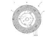
図1は照明装置の正面図、図2は図1のA−A線断面図、図3は照明装置を示す底面図、図4は照明装置の要部を示す断面図、図5は、単体の投光孔よりの投影を説明する構成図、図6は、2つの投光孔よりの投影を説明する構成図、図7は投光孔の断面図、図8(a)は照明装置の要部を示す平面図、図8(b)は図8(a)のB−B線断面図である。 1 is a front view of the lighting device, FIG. 2 is a sectional view taken along line AA of FIG. 1, FIG. 3 is a bottom view showing the lighting device, FIG. 4 is a sectional view showing the main part of the lighting device, and FIG. FIG. 6 is a configuration diagram for explaining projection from two projection holes, FIG. 7 is a sectional view of the projection holes, and FIG. FIG. 8B is a cross-sectional view taken along the line BB of FIG. 8A.
照明装置1は、図1及び図2に示すように、ランプシェード2とランプシェード2を載置し発光体3を立設する基台4とより構成している。 As shown in FIGS. 1 and 2, the illuminating
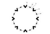
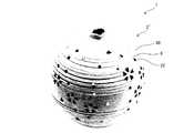
ランプシェード2は、中空略球状に形成し、球形状の頂部10には大径の孔20を設け、球形状の周壁面11には略星形状孔23、略三日月形状孔24、投光孔22を多数穿設し、さらに同周壁面11に条溝30を等間隔に形成している。この球状の周壁面11には、上方から中途部に向かって斜めに多数の投光孔22を密集して穿設し、上方から下方に向かって一定間隔を設けて複数の星形状孔23や複数の略三日月形状孔24を散りばめながら穿設して設けている。 The
そして、このランプシェード2は、図2及び図3に示すように、前述した製造工程により製造された釉薬のない陶磁器とし、底部12に切欠部27と、基台4に立設した発光体3を挿入可能な底部開口28と、脚部となる下面先端が平坦な突起13とを形成しており、基台4上に立設したランプ3に上方よりランプシェード2を被せることにより、同ランプシェード2の底部開口28内にランプ3が挿入され、切欠部27からランプ配線5が引き出されて、さらに上面平坦な突起13が基台4上面14に当接されることで、ランプシェード2が基台4上に載置されることとなる。 As shown in FIGS. 2 and 3, the
基台4は、一定厚みの正方形状に形成され、同基台4の上面14は鏡面加工が施された大理石で構成されている。 The
このような照明装置では、ランプ3を点灯すると、図4に示すように、同ランプ3より放射状に光を放射しており、この放射状に放射された光Lは、ランプシェード2に穿設した投光孔22、各種形状の星形状孔23、三日月形状孔24を透過することで、図1に示すように、周壁面11上の大小複数の円孔による天の川状の成形部29と周壁面11上に一定間隔で離間して散りばめられた複数の星形状孔23及び複数の三日月形状孔24による周壁面11上に点灯する装飾を直視し観賞可能とする効果があり、さらに、各投光孔22を透過した透光は、周囲の投影面体の例えば床面F、壁面W、天井面Rに大小複数の円孔からなる天の川状の成形部29による絵画のような投影像を投影し、一定間隔で離間して散りばめられた複数の星形状孔23及び複数の三日月形状孔24による絵画のような投影像を投影することが可能である。すなわち、鑑賞者にとっては、周壁面11上の複数の投光孔22、星形状孔23、三日月形状孔24を直視したときの明暗と、投光孔22、星形状孔23、三日月形状孔24より周囲の壁面W等に大小複雑な投影像と同投影像の明暗により幻想的な印象を醸し出す効果がある。 In such an illuminating device, when the
また、周壁面11に穿設した投光孔22は、図5に示すように、ランプシェード2の外方に下向きの下り勾配となるように形成した内周面(図7(a)参照)を有しており、内周面を備えた投光孔22から透過した透光は、床面F等上において投影像15を投影することができる。すなわち、内周面21’の断面視における下辺34と床面Fは、角度θ1をなし、また、内周面の断面視における上辺35と床面Fは、角度θ2をなしており、角度θ1と角度θ2は、それぞれ鋭角をなしている。 Further, as shown in FIG. 5, the
かかる角を鋭角とすることにより、内周面21’の断面視下辺34における延長線上の床面Fに投影される透光L2は高輝度となり、また、内周面21’の断面視上辺35における延長線上の床面Fに投影される透光L3は低輝度となることで、ランプシェード2の載置した位置より離れるに連れて投影像15が拡がり最後にはフェード化する効果がある。すなわち、鑑賞者にとっては、フェード化した投影像によりさらに幻想的な印象を醸し出す効果がある。 By making such an angle an acute angle, the translucent L2 projected onto the floor surface F on the extension line in the sectional view
さらに、周壁面11に穿設した投光孔22は、図6に示すように、同周壁面11の上下方向の位置において、一定間隔を設けて形成しており、周壁面11の下方の投光孔22と周壁面11の上方の投光孔22から透過する各透光L4,L5が床面上において2つの投影像15,15を前後方向で重なり合うように2つの投光孔22を周壁面11に穿設している。 Further, as shown in FIG. 6, the
従って、周壁面11に大小複数穿設した投光孔22より透過する透光は、床面上においてランプシェードの載置位置を基準に前後方向に重なり合いながら装飾性の高い投影像を投影することが可能となる効果がある。 Therefore, the translucent light transmitted through the
上述した投光孔22の内周面21’を外方に向かって下向きの下り勾配に形成する以外に、図7(b)に示すように、投光孔22の内周面21’は、下方方向に穿設した外方に向かって拡開状のテーパーに形成してもよい。かかる構成とすることで、ランプ3を点灯した場合、照明装置1の載置位置より下方方向にある周辺の壁面Wや床面Fに円孔形状の投光孔22より透光した光Lが壁面Wに各種形状の投影像15、すなわちフィラメントの投影像51が反転して大きく投影することが可能となる効果がある。 In addition to forming the inner
図7(c)に示すように、投光孔22の内周面21’は、ランプシェード2の内方に向かって拡開状のテーパーに形成してもよい。かかる構成とすることで、ランプ3を点灯した場合、照明装置1の載置位置より水平方向にある周辺の壁面Wや床面Fに投光孔22より透光した光Lが絞られ短い距離で各種形状の投影像15として小さく投影することが可能となる効果がある。 As shown in FIG. 7C, the inner
ランプシェードの周壁面の曲面位置に応じて図7中の投光孔22の内周面の構成を組み合わせることでさまざまな形、透光による陰影の投影像を投影することが可能となる。 By combining the configuration of the inner peripheral surface of the
また、略星形状孔23や略三日月形状孔24を透射した光Lは、略星形状孔23や略三日月形状孔24の像を模様として壁面Wなどに投影させ、さらに、投光孔22より透射した光Lは、ピンホール効果により天井面R、壁面Wや床面Fにランプ3のフィラメント6の形状の像を反転した模様の投影像として投影させることが可能となる。 Further, the light L that has passed through the substantially star-shaped
さらに、照明装置におけるランプシェードの周壁面11には、周方向に等間隔の条溝30を形成している。周壁面11に形成したV字形状の条溝30は、図8(b)に示すように、ランプシェード2の曲率が大きくなるにつれ、条溝30の頂角31の角度αも漸次大きくなるにように形成される。 Further, on the
一方、図8(a)に示すように、投光孔21を透過した光Lのうち、V字形状の条溝30に沿って進行する回折光L1は、V字形状の条溝30を形成する両斜面32,32に反射されながらジグザク状に進行することとなる。 On the other hand, as shown in FIG. 8A, the diffracted light L <b> 1 that travels along the V-shaped
他方、投光孔21より透過した光Lが壁面Wや床面Fに照射された後、反射した光L2は、再度、ランプシェード2の周壁面11に到達し、周壁面11を照らし出すこととなる。このとき周壁面11に形成した下方のV字形状の条溝30は、ランプシェードの曲率が大きいほど頂角31を漸次大きくなるように形成されており、この条溝30を構成する各斜面32,32の面積も下方ほど広くなるため、反射光L2を広い受光面積で受光可能とする構成としている。 On the other hand, after the light L transmitted through the
照明装置1の発光体を点灯すると、暗室内において、略球状の周壁面11に穿設した投光孔22や略星形状孔23などから光Lが透射されて、同照明装置の周辺にある壁体W及び同照明装置の載置床面Fに、略星形状の投影像や、V字形状の投影像などの複雑な形状の模様として大きく投影される。さらに、透過した光Lうち漏光L1が、ランプシェード2の周壁面11のV字形状の条溝30に沿って反射しながら進行することにより、鑑賞者にとって逆光状態にかかわらずランプシェード2の周壁面11を観賞することが可能となり芸術性を向上する効果がある。 When the illuminator of the
かかるV字形状の条溝30により、逆光状態であっても各反射光L1,L2がランプシェード2の周壁面11を浮き立たせて観賞可能にならしめる。また、上述した基台4の上面14は、鏡面加工されており、投光孔21より透射した光Lが基台4上面14で反射されランプシェード2の周壁面11に形成されたV字形状の条溝30に照射されることにより、周壁面11を浮き立たせて観賞可能な構成としている。 Such a V-shaped
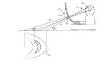
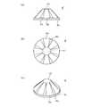
上述した照明装置1は、ランプシェード2の形状を中空略球形状としたが、以下に説明する他の照明装置41は、ランプシェード2の形状を先端尖鋭の中空円錐形状とする点が異なるものである。他の照明装置41の構成においては、照明装置1と同一符号を付して重複説明を省略する。図9は他の照明装置を示す正面図である。図10は他の照明装置の点灯状態示す斜視図である。 Although the
暗室内でランプ3を点灯すると、図10に示すように、周壁面11の後面の細長孔25から透射した光Lが周辺の壁面Wに上下方向、斜め方向に間延びした細長の光として投影され、また、細長孔25の両側に穿設した多数の投光孔22より透射した光Lが天井面Rや壁面Wや床面Fにフィラメントの形状によるV字状の投影像51をランプシェードから離間するにつれ重ね合うように徐々に大きく投影することができる。フィラメントの形状の投影像51の集合体は、絵画のような孔雀が羽根を広げたような造形として観賞することが可能となる。しかも、投光孔21より透光L1は、周壁面11のV字形状の条溝30に光L1が反射しながら進行し、さらに、天井面R、壁体Wや床面Fで乱反射した光L2はV字形状の条溝30に到達することにより、ランプシェード2の先端尖鋭の中空円錐形状を浮き立たせて、逆光状態においても観賞可能となる。また、略細長孔25や桜の花びら形状孔26を透射した光Lは、略細長孔25の投影像50や桜の花びら形状孔26の投影像52を床面F、壁面W、天井面Rに投影することで、先のフィラメントの投影像51との相乗効果で絵画のような複雑な投影像を作り出して観賞することができる。 When the
なお、周壁面11に穿設する孔の形状としては、略星形状孔23、略三日月形状孔24、略細長孔25や桜の花びら形状孔26に限らず芸術性を醸し出す貫通孔の形状であれば、これらの形状に限定するものではない。 The shape of the hole formed in the
また、投光孔22は、拡開状のテーパーとすることでピンホール効果によりフィラメント6の形状の虚像を投影できる反面、光量が少ないため虚像の造影が暗くなる。 In addition, the
投光孔22の径が小さい場合には、ピンホール効果によりランプのフィラメント6の形状が投影面に投影される。例えば、フィラメント6の形状がひし形の場合には、略V字形状の模様が投影されるが、この孔の径を可変することで、虚像の大きさや明るさを調整することが可能となる。 When the diameter of the
なお、基台には、大理石を用いたが、人工大理石、無機材、樹脂、金属、ガラス等を用いたものでもよく材質を限定するものではない。 In addition, although marble was used for the base, artificial marble, inorganic material, resin, metal, glass or the like may be used, and the material is not limited.
[ガラス粒子つきランプシェード]
上述したように本発明では、陶磁器の周壁に多数の投光孔22や細長孔25や花びら形状孔26やV字形状の条溝30等を形成し、陶磁器内部の発光体3からランプシェード2周辺に配した投影面体に発光体3の光源に類する光影像を投影するものである。
しかも、本発明では、かかるランプシェード2の投影像形成技術に加えて、ガラス粒子やダイヤモンド粒子をランプシェード2の周壁に埋没或いは貼着したことに大きな特徴を有する。[Lamp shade with glass particles]
As described above, in the present invention, a large number of light projecting
In addition to the projection image forming technique of the
すなわち、ランプシェード2の中空器体の周壁面にかかるスワロフスキー粒子(なお、ここで称する「スワロフスキー」とは、登録商標である。)のようなガラス粒子やダイヤモンド粒子を埋没、貼着することにより、中空器体に配設した発光体3の光源形状、例えば、フィラメントの形状の光影像がガラス粒子を透光する際に縮尺した多数の影光像を近辺の投影面体に投影するということを発明者は発見した。That is, by burying and sticking glass particlesor diamond particles such as Swarovski particles(herein, “Swarovski” is a registered trademark) applied to the peripheral wall surface of the hollow body of the
発明者は、かかるガラス粒子やダイヤモンド粒子の乱反射機能が単なる光反射機構だけではなく近辺に配した投影面体に投影した際に、発光体3の光源の形が多数の投光孔等からの投影像と同形でかつ小さな縮尺像として、しかも、ガラス粒子やダイヤモンド粒子のカット面の数だけ多数投影されるということを発見した。The inventor found that the diffused reflection function of such glass particlesand diamond particles was projected not only on a simple light reflecting mechanism but also on a projection plane arranged in the vicinity, so that the shape of the light source of the
従って、投影面体に投影される造形投影像は、投光孔等からの基本的な大きさの映像に加えて、その映像近辺にはそれと同形にもかかわらず縮尺された多数の光の映像が投影されることになる。 Therefore, in addition to the basic size image from the projection hole etc., the model projection image projected on the projection plane has a large number of scaled light images in the vicinity of the image, despite the same shape. Will be projected.
かかる光映像は、従来のランプシェード2からの単純な投影像と比較し、複雑でバリエーションに富んだ芸術的な投影光を形成することができる。
以下、ガラス粒子を配した釉薬を施さない陶磁器製のランプシェードについて詳細に説明する。Such an optical image can form an artistic projection light that is complex and rich in variations as compared with a simple projection image from the
Hereinafter, a ceramic lamp shade without glass glaze will be described in detail.
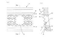
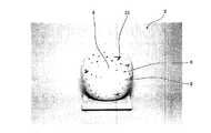
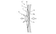
図11に示すように、上記のように構成した釉薬を施さない陶磁器製のランプシェードにおいて周壁11には多数の凹部7を形成して、その凹部7内にガラス粒子8を埋設している。一部の凹部7の底部は、ランプシェード2内部に貫通している。また、底面9には、外部方向から内部方向に漏斗形状に構成されている。 As shown in FIG. 11, in the ceramic lamp shade without the glaze configured as described above, a large number of
ガラス粒子8やダイヤモンド粒子は、多角形状に形成され、底部を備えており、底部の面8bから入射した光Lを前面8aの多角面から放射可能な透明材質としている。また、ガラス粒子8やダイヤモンド粒子は透明なものや赤色、青色、黄色、緑色等の多数の色彩からなる。このような色彩を施したガラス粒子8やダイヤモンド粒子を用いることにより光源の光に着色して更なる光のオブジェのバリエーションを形成することができる。The
ガラス粒子8は、透明な透光性ビーズであってもよい。透明なガラス粒子8やダイヤモンド粒子を用いることにより、光源や外からの光の拡散が一段と向上して、ガラス粒子8やダイヤモンド粒子のカットが複雑な分乱光機能が向上して乱光輝度を目立つように拡大することができる。
図11及び図12に示すように、ガラス粒子8やダイヤモンド粒子は、41面体の多角形状の構造を有しており、クラウン部、ガードル部、パビリオン部からなる。また、ガラス粒子の材質は、ガラスに酸化鉛を24%以上含有し、透明度が高く、屈折率1.52以上である。As shown in FIGS. 11 and 12, the
クラウン部8cは、平面視略8角形のテーブル8fと2等辺三角形のスターファセット8gと上部メインファセット8hとからなり、スターファセット8gが8面形成され、上部メインファセット8hが8面形成される。 The
ガードル部8dは、クラウン部8cとパビリオン部8eとの境部分である。 The
パビリオン部8eは、2等辺三角形の下部ガードルファセット8iと下部メインファセット8jとからなり、下部ガードルファセット8iが8面形成され、下部メインファセット8jが16面形成される。 The
ガラス粒子8のパビリオン部8eから光源の光が入射する場合について説明する。1つの光源の光が8個の各下部ガードルファセット8iと16個の各下部メインファセット8jにそれぞれ入射し、ガラス粒子8内を反射して、クラウン部8cの8個の各スターファセット8gと8個の各上部メインファセット8hからそれぞれ放射され、図14に示すように幅が細い縮尺形状のV字形状の大小の投影像61,62を交互に仮想円C上に並べつつ、周囲の投影面体に投影している。The case where the light of the light source enters from the
ランプシェード2の外表面には、天の川や花をイメージした多数の凹部7を形成しており、これら凹部7には多角形状のガラス粒子8の底部周縁が埋設している。この凹部7の内底面は、ランプシェード2の内部と貫通してもよいし、或いは、貫通せずに薄膜を設けたものでもよい。このような各種類の凹部7にガラス粒子を設けた形態について、より具体的に以下の図15から図17を用いながら説明する。 On the outer surface of the
図15に示すように、ガラス粒子8は、ランプシェード2の凹部7内、すなわち、ランプシェード2の周壁11の厚みの間に埋設している。凹部7の内周面21’はランプシェード2の内側から外側に向けて拡開状のテーパーに形成している。 As shown in FIG. 15, the
凹部7の内底部は、ランプシェード2内に貫通しており、光源の光は透明なガラス粒子8の底面からガラス粒子内に入射し、入射した光の一部は凹部内周面によって反射されて、これらの光がガラス粒子8の前面側の各カット面から各方向に乱放射されて、ランプシェード2の側方の投影面体、例えば、壁面Wや床面FにV字形状の投影像61,62を投影することができる。 The inner bottom portion of the
多角形状のガラス粒子8のカット面から放射して投影面体に結像するV字形状の投影像61,62は、投光孔22から直接放射して投影面体に結像するV字形状の投影像より線の幅が細い縮尺形状のものとなる。また、線の幅が細い投影像61,62は、ガラス粒子8の前面側の各カット面から放射されるため、側方の投影面体に複数の縮尺投影像を一度に多数投影することができる。すなわち、1つの投光孔22から投影する像は1つであったが、ガラス粒子8を透過してカット面から投影する像は、カット面の数だけ複数となり、しかも、投光孔22からの投影像の縮尺像となり、より幻想的な投影像を醸し出すことができる。 V-shaped
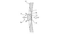
図11に示すように、ガラス粒子8がランプシェード2の投光孔22を貫通して、ランプシェード2の内壁面より内側に突出した態様としている。光源からの光がランプシェード2の内壁面より内側に突出したガラス粒子8のパビリオン部8eの各カット面から入射して、その内部を乱反射した光はガラス粒子8の前面側のクラウン部8cの各カット面から放射され、ダイヤモンドのような輝きを放つとともに、ランプシェード2の側方の投影面体、例えば、壁面Wや床面FにV字形状の投影像61,62を投影することができる。As shown in FIG. 11, the
ガラス粒子8を凹部7に貼着した場合には、ガラス粒子8のパビリオン部8eがランプシェード2の内壁面より内側に突出した態様となる。光源からの光がパビリオン部8eの各下部メインファセット8jに入射したのちクラウン部8cの各スターファセット8gと各上部メインファセット8hから放射され、幅が細い縮尺形状のV字形状を仮想円C(図14参照)上に並べつつ、周囲の投影面体に投影している。ランプシェード2が投影面体から大きく離間すると仮想円Cの径は大きくなり、幅が細い縮尺形状のV字形状の像が大きく投影されることとなる。幅が細い縮尺形状のV字形状の投影像のうち8個は、輝度も明るく鮮明に投影され、その他の像の8個は、ガラス粒子8の分光機能によって、輝度も暗くかつ虹色に投影されることとなる。When the
図16に示すように、ランプシェード2の凹部7の底面は、貫通しておらず、約1mm程度の厚みの薄膜7aを形成している。凹部7の薄膜7aに浸透性の高い樹脂16を含浸させてガラス粒子8を接着している。この樹脂16が膜の微小孔に含浸して、硬化する際に膜に微細なクラック17を発生させる。クラック17により薄膜7aは、ランプシェード2の内側と部分的に貫通した状態となる。
光源からの光は、微小クラック17を透過してガラス粒子8のパビリオン部8eより入射し、ガラス粒子の内部で乱反射した光がクラウン部8cのカット面から放射され、弱い輝きを放つこととなる。As shown in FIG. 16, the bottom surface of the
The light from the light source passes through the
図17に示すように、ランプシェード2の凹部7に近接する周辺位置、例えば、3mm程度の位置にガラス粒子8の下半分を埋没させる。すなわち、凹部7の底面は、貫通しておらず、薄膜7aを残している。凹部7の薄膜7aに浸透性の高い樹脂16を含浸させてガラス粒子8を接着している。
光源からの光は投光孔22から透過して近接したガラス粒子8のクラウン部8cの一部のカット面より入射して乱反射したのち、テーブル8fから放射され、弱い輝きを放つこととなる。As shown in FIG. 17, the lower half of the
The light from the light source is transmitted through the
また、三日月形状の貫通した孔に近接した位置に凹部を複数設けて、複数の凹部7にガラス粒子8をそれぞれ埋没するようにしてもよい。このように大きな三日月形状孔24の近辺に複数のガラス粒子8を設けることにより、光源からの光が三日月形状孔24より透光して、ガラス粒子8のクラウン部8cの一カット面より入射し、ガラス粒子8内で反射してガラス粒子8のクラウン部8cの他のカット面から放射される。投光孔22に比べて三日月形状孔24から透光が多いために孔の周囲に設けた複数のガラス粒子8に強い透光が入射することとなる。各ガラス粒子8が投光孔22の周囲に配したガラス粒子8に比べて明るく輝きを放つこととなり幻想的な雰囲気を醸し出すこととなる。 Alternatively, a plurality of recesses may be provided at positions close to the crescent-shaped through holes, and the
さらに、貫通した凹部に設けたガラス粒子では、光源からの光がガラス粒子の底面から入射し、ガラス粒子の内部を乱反射した光はガラス粒子の前面側の各カット面から放射され、ダイヤモンドのような輝きを放つとともに、ランプシェードの側方の投影面体、例えば、壁面Wや床面FにV字形状の投影像61,62を投影することができる。 Furthermore, in the glass particle provided in the recessed part which penetrated, the light from the light source is incident from the bottom surface of the glass particle, and the light irregularly reflected inside the glass particle is emitted from each cut surface on the front side of the glass particle, like a diamond. V-shaped
[ガラス粒子の他の例]
図18に示すガラス粒子8’は、通常のガードル部を除いた8角形のテーブル8’fと略台形のスターファセット8’gと二等辺三角形の上部メインファセット8’hと反射鏡8’xとからなり、スターファセット8’gや上部メインファセット8’hがそれぞれ8面形成されている。[Other examples of glass particles]
18 includes an octagonal table 8′f excluding a normal girdle part, a substantially
図19に示すように、ガラス粒子8’をランプシェード2の投光孔22に近接させて貼り付けると、光源の光が投光孔22より透光して、その光の一部が条溝30内を反射してガラス粒子8’のカット面に入射するとともに、投光孔22より透光した光がガラス粒子8’のカット面に直接入射することとなる。ガラス粒子に入射したこれらの光が反射鏡8’xにより反射されて、ガラス粒子8’のカット面より放射されて、弱い輝きを放ち、鑑賞者に美感を生起させることとなる。 As shown in FIG. 19, when the
上述したガラス粒子を凹部に貼着したランプシェードが図20及び図21となる。すなわち、図20は、ガラス粒子を凹部に貼着したランプシェードの正面図であり、図21はランプシャードの背面図である。The lamp shade in which theglass particles described above are stuck in the recesses is shown in FIGS. That is, FIG. 20 is a front view of a lamp shade in whichglass particles are adhered to the recesses, and FIG. 21 is a rear view of the lamp shard.
このランプシェード2の背面側から放射した光が図22に示す投影面体としての壁面Wや床面Fに投影されることとなる。 The light radiated from the back side of the
図21中のガラス粒子8のクラウン部8cのカット面から放射した光が、図22中の投影面体の壁面Wにおける右側上方面に、幅が細い縮尺形状のV字形状の像61,62を仮想円の縁に沿って等間隔にそれぞれ投影される。ランプシェード2の投光孔22や凹部7に貼着したガラス粒子8から放射する光が投影面体に折り重なるように複雑に投影されることにより、美しい映像を醸し出すとともに、ランプシェード2の正面の投光孔22からの光や凹部7に貼着したガラス粒子8から放射する光が鑑賞者に美感を生起されることとなる。Light radiated from the cut surface of the
このように各ガラス粒子から放射する光の強さが異なることで、鑑賞者に光の錯覚の楽しさを倍増させることができる。また、光源からの強い光が入射するガラス粒子では、ガラス粒子内で反射した光が各カット面からそれぞれ放射され、光源のV字形状のフィラメント形態に類似した投影像を微小な形態で側方に配した投影面体としての壁面、床面、天井面等に投影することができる。 Thus, since the intensity of light emitted from each glass particle is different, it is possible for the viewer to double the illusion of light. In addition, in glass particles to which strong light from a light source is incident, the light reflected in the glass particles is emitted from each cut surface, and a projected image similar to the V-shaped filament shape of the light source is laterally formed in a minute form. Can be projected onto a wall surface, a floor surface, a ceiling surface, or the like as a projection surface body arranged on the screen.
光源にLED光源を使用した場合には、凹部に貼着したガラス粒子の各カット面から放射する光が投影面体に光の点としてそれぞれ投影されることとなる。この投影面体の光の点の大きさは、投光孔から出射した光が投影面体に投影された光の円より小さいものとなる。また、光の点の明るさも光の円よりも若干暗いものとなる。When an LED light source is used as the light source, the light emitted from each cut surface of theglass particles adhered to the recess is projected as a light spot on the projection plane. The size of the light spot on the projection plane is smaller than the circle of light projected from the projection hole on the projection plane. The brightness of the light spot is also slightly darker than the light circle.
また、LED光源は、赤色(R)のLED素子、緑色(G)のLED素子、青色(B)のLED素子からなるRGBのLED光源としてもよい。3色のLED光源を点灯した場合のランプシェードからの光の動向について詳説する。 The LED light source may be an RGB LED light source including a red (R) LED element, a green (G) LED element, and a blue (B) LED element. The trend of light from the lamp shade when the three color LED light sources are turned on will be described in detail.
3色のLED光源からの光は投光孔22から透過して投影面体に照射される。
また、図11に示す投光孔22に埋め込んだガラス粒子8ではそのパビリオン部8eにLED光源からのRの光、Gの光、Bの光が入射する。特に、下部メインファセット8jの各面にRの光、Gの光、Bの光の何れかの光が入射することによりクラウン部8cの各面から出射する光もRの光、Gの光、Bの光の何れか1色の光となり、鑑賞者は下部メインファセット8jの面ごとに異なる色として視認することができる。さらに、クラウン部8cの各面から出射した光とその他のガラス粒子8から出射した光は投影面体において丁重して、RGB以外の色彩、例えば、白色光となって視認することができる。Light from the three-color LED light sources is transmitted through the
Moreover, in the
さらに、図16に示す凹部7に埋設したガラス粒子では凹部底の薄膜7aのクラック17から漏れるLEDの光がガラス粒子8に入射して、ガラス粒子8を弱く輝かす。
さらにまた、図17に示す投光孔22に近接して埋設したガラス粒子8では、投光孔22からのLED光がガラス粒子8に斜めから入射して、特に後述するランプシェードの色彩の影響を受けて、輝くこととなる。Further, in the glass particles embedded in the
Furthermore, in the
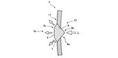
すなわち、本照明装置の各種の光は図30に示す以下の(1)から(6)の光と複雑に組み合わされてランプシェードの周壁を照らしたり、ガラス粒子を輝かしたり、投影面体を照射することなる。
(1)LED光源のRGB色の光が投光孔から透過する光x1。
(2)LED光源のRGB色の光とランプシェードの色彩と組み合されて投光孔から透過する光x2。
(3)LED光源のRGB色の光が投光孔に埋設したガラス粒子に入射してその後出射する光y1。
(4)LED光源のRGB色の光がランプシェードの色彩と組み合され、ガラス粒子に入射してその後出射する光y2。
(5)LED光源のRGB色の光が投光孔に近接した凹部のガラス粒子に入射してその後出射する光y3。
(6)ガラス粒子に色彩を施し、上記(3)から(5)の構成において、色彩付きのガラス粒子から出射する光。That is, various lights of this illumination device are combined with the following light (1) to (6) shown in FIG. 30 in a complicated manner to illuminate the peripheral wall of the lampshade, to shine glass particles, and to irradiate the projection plane. It will be different.
(1) Light x1 through which RGB light from the LED light source passes through the light projection hole.
(2) Light x2 which is combined with the RGB light of the LED light source and the color of the lamp shade and is transmitted through the light projection hole.
(3) The light y1 that the RGB light of the LED light source enters the glass particles embedded in the projection hole and then exits.
(4) Light y2 in which the RGB light of the LED light source is combined with the color of the lamp shade, enters the glass particles, and then exits.
(5) Light y3 emitted from the RGB light from the LED light source incident on the glass particles in the recesses close to the projection hole and then emitted.
(6) Light emitted from the colored glass particles in the above configurations (3) to (5) after coloring the glass particles.
また、色彩を施したガラス粒子を用いる際に、ガラス粒子の色彩に合わせてランプシェード自体に色彩を施すようにしてもよい。 Further, when using glass particles that have been colored, the lamp shade itself may be colored according to the color of the glass particles.
すなわち、図23から図25に示すように、ランプシェード2’の素材の粘土に顔料を混ぜて色彩を施すようにしている。例えば、ピンク色の顔料を粘土に混ぜて、ピンク色のランプシェード2’を形成し、ランプシェード2’の周壁11に形成した凹部7にピンク色のガラス粒子8を埋没、貼着する。
特に、ランプシェード2’の凹部7底部の厚みは、薄く形成し、中空内の発光体3の光を透かすことができる程度の厚みに形成する。このように凹部7底部の厚みを薄くすることで凹部底部から漏れる光の透光率を向上させて、透かしを構成することができる。That is, as shown in FIG. 23 to FIG. 25, the pigment is mixed with the clay of the material of the
In particular, the thickness of the bottom of the
さらに、凹部7にガラス粒子8を貼着することで、発光体を点灯した際に、凹部7底部から弱い光が漏れて、その光がガラス粒子8の底面から入射して、前面8aの多角面から放射される。この多角面から放射されたピンク色の光の一部が十字形状の凹部7に沿って進みことで、鑑賞者は十字形状の光として視認することができる。 Furthermore, by sticking the
図27から図29に示すように、ランプシェード2’の表面に深い条溝30を形成し、深い条溝30の底部を薄くて透かしを形成するようにしてもよい。
すなわち、深い条溝30に近接した箇所に投光孔22を穿設し、深い条溝30にガラス粒子8を埋設、貼着する。As shown in FIGS. 27 to 29, a
That is, the
深い条溝30にガラス粒子8を貼着し、発光体を点灯した際に、深い条溝30底部から弱い光が漏れて、さらに近接した投光孔22から出射した光がガラス粒子8の底面および側面から入射して、前面8aの多角面から色彩光として放射される。 When the
ランプシェード2’周壁11の色彩とガラス粒子8の色彩とガラス粒子8からの投影像が組み合わされて、それぞれの色彩と各光により幻想的な雰囲気を醸し出すことができる。 The colors of the
上述した実施例では、釉薬を施さない陶磁器でランプシェードを形成した例を挙げたが、顔料を混ぜた釉薬を用いて、陶磁器のランプシェードを釉薬に漬けて色彩を施すようにしてもよい。 In the embodiment described above, an example in which the lamp shade is formed with ceramics without glaze is given, but the glaze may be soaked in glaze using glaze mixed with pigment to give color.
すなわち、図26に示すように、ランプシェードの表面に凹部7を形成し、凹部7底部の厚みを薄くて透かしを形成する。その後、ランプシェードを素焼きして、例えばピンク色の顔料を混ぜた釉薬に素焼きのランプシェードを漬ける。 That is, as shown in FIG. 26, the
ランプシェード2’’表面の凹部7には、釉薬18のたまり18aが形成され、釉薬18が厚く塗られた箇所と薄く塗られた箇所が形成される。その後、ランプシェードを焼成すると釉薬たまり18aの箇所とそれ以外の箇所では色彩に濃淡が異なって現われる。 In the
凹部7の底部にピンク色のガラス粒子8を埋没、貼着する。例えば、ピンク色の濃淡のランプシェード2’’周壁11にピンク色のガラス粒子8を貼着し、中空器内の発光体を点灯すると、ピンク色の濃い凹部7に貼着したガラス粒子8は深いピンク色となり、深いピンク色の光を乱反射し、他方のピンク色の薄い周壁に貼着したガラス粒子8は薄いピンク色となり、淡いピンク色の光を乱反射する。このように各ガラス粒子8が生起する濃淡光により、ランプシェード2’’周壁11や投影面体に色彩のグラデーションが形成される。さらに、この色彩のグラデーション効果とガラス粒子からの投影像が組み合わされて幻想的な雰囲気を醸し出すことができる。
なお、ランプシェードとガラス粒子の色彩は同一色である必要はなく、例えば、ピンク色のランプシェードにピンク色、青色、緑色等の複数種類のガラス粒子を埋没、貼着するようにしてもよい。このような複数色のガラス粒子を使用することで、光のオブジェのバリエーションを適宜変更することができる効果がある。 Note that the colors of the lamp shade and the glass particles do not have to be the same color. For example, a plurality of types of glass particles such as pink, blue, and green may be embedded and adhered to a pink lamp shade. . By using such multi-colored glass particles, there is an effect that the variation of the light object can be appropriately changed.
なお、ランプシェードの透かしは、ランプシェード周壁の投光孔に釉薬の膜を形成し、投光孔に膜が張ったまま焼成したものであってもよい。 The watermark of the lampshade may be obtained by forming a glaze film on the projection hole on the peripheral wall of the lampshade and firing the film while the film is stretched on the projection hole.
以上、本発明の好ましい実施の形態について説明したが、本発明は係る特定の実施形態に限定されるものではなく、特許請求の範囲に記載された本発明の要旨の範囲内において、種々の変形・変更が可能である。 The preferred embodiments of the present invention have been described above. However, the present invention is not limited to the specific embodiments, and various modifications can be made within the scope of the gist of the present invention described in the claims.・ Change is possible.
1 照明装置
2 ランプシェード
3 ランプ
4 基台
5 ランプ配線
6 フィラメント
7 凹部
8 ガラス粒子
8a 前面
8b 底部
8c クラウン部
8d ガードル部
8e パビリオン部
8f テーブル
8g スターファセット
8h 上部メインファセット
8i 下部ガードルファセット
8j 下部メインファセット
9 底面
10 頂部
11 周壁面
12 底部
13 突起
14 上面
15 投影像
16 樹脂
17 クラック
20 孔
21’ 内周面
22 投光孔
23 星形状孔
24 三日月形状孔
25 細長孔
26 花びら形状孔
27 切欠部
28 底部開口
29 成形部
30 条溝
31 頂角
32 斜面
34 下辺
35 上辺
61 投影像
62 投影像DESCRIPTION OF
Claims (5)
Translated fromJapanese前記ランプシェードは陶磁器とした中空器体にて形成すると共に、周壁面外面には多数の投光孔を、また、その近接する周辺位置には凹部を形成し、
ランプシェードの外表面には、多角形状の透明なガラス粒子やダイヤモンド粒子を配設すると共に、
ガラス粒子やダイヤモンド粒子は、平面視略8角形のテーブルと2等辺三角形のスターファセットと上部メインファセットとからなるクラウン部と、2等辺三角形の山型の下部ガードルファセットと下部メインファセットとからなるパビリオン部と、クラウン部とパビリオン部との境部分であるガードル部より構成し、
ガラス粒子やダイヤモンド粒子はランプシェードの投光孔を貫通して、ランプシェードの内壁面より山型のパビリオン部を内側に突出して埋設し、発光体としての光源からの光がランプシェードの内壁面より内側に突出したガラス粒子やダイヤモンド粒子のパビリオン部の各カット面から入射して、その内部を乱反射した光はガラス粒子やダイヤモンド粒子の前面側のクラウン部の各カット面から放射するように構成し、
しかも、一部のガラス粒子やダイヤモンド粒子はランプシェードの投光孔に近接する周辺位置に形成した凹部中に同ガラス粒子やダイヤモンド粒子の下半分の山形形状のパビリオン部を埋没して配設し、発光体からの光は投光孔から透過して前記の周辺に近接して配設したガラス粒子やダイヤモンド粒子のクラウン部のカット面より入射して乱反射したのち、テーブルから放射され、弱い輝きを放つように構成した照明装置。In a lighting device comprising a hollow lamp shade having a fixed shape, a light emitter installed in the lamp shade, and a base on which the light emitter is erected,
The lamp shade is formed with a hollow body made of ceramic, and a large number of light projecting holes are formed on the outer surface of the peripheral wall surface, and a concave portion is formed at a peripheral position adjacent thereto,
The outer surface of the lampshade, thereby disposing the transparentglass particleschildren and diamond particles polygonal,
Glass particles and diamond particles are a pavilion consisting of a substantially octagonal table in plan view, a crown part composed of an isosceles triangular star facet and an upper main facet, and an isosceles triangular mountain-shaped lower girdle facet and lower main facet. Part, and the girdle part that is the boundary part between the crown part and the pavilion part,
Glass particles and diamond particles pass through the projection hole of the lamp shade, and the mountain-shaped pavilion part protrudes inward from the inner wall surface of the lamp shade so that the light from the light source as the light emitter is reflected on the inner wall surface of the lamp shade. Light is incident from each cut surface of the pavilion part ofglass particles and diamond particles protruding inward, and the light diffusely reflected from the inside is emitted from each cut surface of the crown part on the front side of theglass particles and diamond particles. And
In addition, someglass particles and diamond particles are disposed by embedding a chevron-shaped pavilion in the lower half of theglass particles and diamond particles in a recess formed in a peripheral position close to the projection hole of the lampshade. The light from the illuminant is transmitted through the projection hole and incident from the cut surface of the crown portion of theglass particles or diamond particles arranged in the vicinity of the periphery, and then diffusely reflected, and then is emitted from the table and weakly shines. A lighting device configured to emit light.
Priority Applications (1)
| Application Number | Priority Date | Filing Date | Title |
|---|---|---|---|
| JP2015122268AJP6117859B2 (en) | 2014-06-18 | 2015-06-17 | Lighting device |
Applications Claiming Priority (3)
| Application Number | Priority Date | Filing Date | Title |
|---|---|---|---|
| JP2014125273 | 2014-06-18 | ||
| JP2014125273 | 2014-06-18 | ||
| JP2015122268AJP6117859B2 (en) | 2014-06-18 | 2015-06-17 | Lighting device |
Publications (2)
| Publication Number | Publication Date |
|---|---|
| JP2016021388A JP2016021388A (en) | 2016-02-04 |
| JP6117859B2true JP6117859B2 (en) | 2017-04-19 |
Family
ID=55266098
Family Applications (1)
| Application Number | Title | Priority Date | Filing Date |
|---|---|---|---|
| JP2015122268AExpired - Fee RelatedJP6117859B2 (en) | 2014-06-18 | 2015-06-17 | Lighting device |
Country Status (1)
| Country | Link |
|---|---|
| JP (1) | JP6117859B2 (en) |
Families Citing this family (5)
| Publication number | Priority date | Publication date | Assignee | Title |
|---|---|---|---|---|
| JP6851583B2 (en)* | 2016-12-15 | 2021-03-31 | 哲 鶴崎 | Backlit lighting device for shaped objects |
| JP6375077B1 (en)* | 2018-03-16 | 2018-08-15 | Atv株式会社 | Electronic cymbals |
| KR102186626B1 (en)* | 2020-02-07 | 2020-12-08 | (주)지리산황토예술촌 | Axial Lightening Light Means |
| KR102410050B1 (en)* | 2021-07-19 | 2022-06-22 | 김민정 | Constellation storage box for line bulbs |
| DE102021127904A1 (en) | 2021-10-27 | 2023-04-27 | Bayerische Motoren Werke Aktiengesellschaft | automotive lighting module |
Family Cites Families (10)
| Publication number | Priority date | Publication date | Assignee | Title |
|---|---|---|---|---|
| JPH0446315U (en)* | 1990-08-24 | 1992-04-20 | ||
| JP2875674B2 (en)* | 1992-01-24 | 1999-03-31 | 正 高橋 | Lighting shade, lighting device, and method for manufacturing the shade |
| JP3188531B2 (en)* | 1992-09-25 | 2001-07-16 | 富士通株式会社 | Multiplex communication method and apparatus |
| JP2707405B2 (en)* | 1993-11-11 | 1998-01-28 | 衛 杉浦 | Lighting umbrella |
| JPH11301200A (en)* | 1998-04-15 | 1999-11-02 | Mitsuzo Yamada | Monument |
| JP2004139811A (en)* | 2002-10-17 | 2004-05-13 | Hideo Nakamura | Lighting shade |
| JP2005019369A (en)* | 2003-06-26 | 2005-01-20 | Koji Hori | Energy-saving auxiliary lighting apparatus |
| US7854532B2 (en)* | 2007-01-18 | 2010-12-21 | Schonbek Worldwide Lighting, Inc. | Fixture and a method for servicing or cleaning an ornamental fixture |
| JP5296391B2 (en)* | 2008-01-31 | 2013-09-25 | 京子 岡野 | Lighting device |
| US20120069581A1 (en)* | 2010-09-22 | 2012-03-22 | Chi Gon Chen | Outdoor light having translucent mosaic lens |
- 2015
- 2015-06-17JPJP2015122268Apatent/JP6117859B2/ennot_activeExpired - Fee Related
Also Published As
| Publication number | Publication date |
|---|---|
| JP2016021388A (en) | 2016-02-04 |
Similar Documents
| Publication | Publication Date | Title |
|---|---|---|
| JP6117859B2 (en) | Lighting device | |
| JP6250541B2 (en) | Candle light LED bulb | |
| US9453626B2 (en) | Decorative lamp with relaxing action | |
| JP2014522094A5 (en) | ||
| CN201688265U (en) | LED stripped shadow wall lamp | |
| JP2011253154A (en) | Light guide body, illumination unit, game board unit, and pachinko game machine | |
| JP5089932B2 (en) | Decorative members, lamps, and ornaments | |
| JP5296391B2 (en) | Lighting device | |
| JP5531302B2 (en) | Lighting device | |
| JP2001137436A (en) | Light-emitting display device | |
| KR200456219Y1 (en) | Lighting lamp | |
| CN203413496U (en) | LED (Light Emitting Diode) ceiling lamp | |
| CN202092007U (en) | Light-transmitting panel structure of art lamps and lanterns | |
| CN2085902U (en) | Adjustable colour lamps and lanterns | |
| TWM404310U (en) | Art lamps having light transmissive decoration plate structure | |
| US20070053183A1 (en) | Decorative Illuminant | |
| KR200451237Y1 (en) | Luminaires with reflectors | |
| CN106907685A (en) | A kind of color gradients lamp | |
| CN206929658U (en) | Novel intelligent decorative down lamp | |
| JP6055053B1 (en) | Backlight illumination device for shaped body | |
| WO2018109901A1 (en) | Backlight illuminator for molded body | |
| JP2011104974A (en) | Decorative body | |
| CN2515529Y (en) | Cover with gain glow effect | |
| KR20140043603A (en) | A lighting ornament | |
| KR200206899Y1 (en) | Light emitting board |
Legal Events
| Date | Code | Title | Description |
|---|---|---|---|
| A871 | Explanation of circumstances concerning accelerated examination | Free format text:JAPANESE INTERMEDIATE CODE: A871 Effective date:20160113 | |
| A977 | Report on retrieval | Free format text:JAPANESE INTERMEDIATE CODE: A971007 Effective date:20160415 | |
| A975 | Report on accelerated examination | Free format text:JAPANESE INTERMEDIATE CODE: A971005 Effective date:20160420 | |
| A131 | Notification of reasons for refusal | Free format text:JAPANESE INTERMEDIATE CODE: A131 Effective date:20160426 | |
| A521 | Request for written amendment filed | Free format text:JAPANESE INTERMEDIATE CODE: A523 Effective date:20160530 | |
| A521 | Request for written amendment filed | Free format text:JAPANESE INTERMEDIATE CODE: A523 Effective date:20160627 | |
| A131 | Notification of reasons for refusal | Free format text:JAPANESE INTERMEDIATE CODE: A131 Effective date:20161004 | |
| A521 | Request for written amendment filed | Free format text:JAPANESE INTERMEDIATE CODE: A523 Effective date:20161202 | |
| TRDD | Decision of grant or rejection written | ||
| A01 | Written decision to grant a patent or to grant a registration (utility model) | Free format text:JAPANESE INTERMEDIATE CODE: A01 Effective date:20170307 | |
| A61 | First payment of annual fees (during grant procedure) | Free format text:JAPANESE INTERMEDIATE CODE: A61 Effective date:20170323 | |
| R150 | Certificate of patent or registration of utility model | Ref document number:6117859 Country of ref document:JP Free format text:JAPANESE INTERMEDIATE CODE: R150 | |
| R250 | Receipt of annual fees | Free format text:JAPANESE INTERMEDIATE CODE: R250 | |
| R250 | Receipt of annual fees | Free format text:JAPANESE INTERMEDIATE CODE: R250 | |
| LAPS | Cancellation because of no payment of annual fees |