JP6116874B2 - Syringe - Google Patents
SyringeDownload PDFInfo
- Publication number
- JP6116874B2 JP6116874B2JP2012258706AJP2012258706AJP6116874B2JP 6116874 B2JP6116874 B2JP 6116874B2JP 2012258706 AJP2012258706 AJP 2012258706AJP 2012258706 AJP2012258706 AJP 2012258706AJP 6116874 B2JP6116874 B2JP 6116874B2
- Authority
- JP
- Japan
- Prior art keywords
- piston
- holder
- nozzle
- injection
- syringe
- Prior art date
- Legal status (The legal status is an assumption and is not a legal conclusion. Google has not performed a legal analysis and makes no representation as to the accuracy of the status listed.)
- Active
Links
Images


Landscapes
- Infusion, Injection, And Reservoir Apparatuses (AREA)
Description
Translated fromJapanese本発明は、注射目的物質を注射対象領域に注射する注射器に関する。 The present invention relates to a syringe for injecting a substance to be injected into an injection target region.
火薬の点火により生じる燃焼ガスのエネルギーを利用して、注射成分を射出する注射器が広く開示されている。例えば、特許文献1に記載の注射器では、推進薬の燃焼により、ピストンと一体に形成された推進表面体が加圧され、該推進表面体の外周面とハウジングの内面とで画定される進路に沿って該推進表面体が推進することになる。そして、推進表面体と一体的に形成されたピストンが、該推進表面体の推進に伴って、該ピストンの外周面とハウジングの内面とで画定される別の進路に沿って推進する。この最終的なピストンの推進により、ピストンの前方に配置された注射成分が射出される。 2. Description of the Related Art A syringe that ejects an injection component by using energy of combustion gas generated by ignition of an explosive is widely disclosed. For example, in the syringe described in
注射対象領域に対して注射目的物質を送り込む場合、当該注射目的物質を所定の場所に届けるべく、射出される注射目的物質にエネルギーを付与する駆動部が注射器に設けられる。そして、当該駆動部によって付与されたエネルギーを注射目的物質に伝えることで、効率的な且つ正確な注射の実現が図られることになる。ここで、注射目的によって注射目的物質に含まれる成分や、該成分を送り込むべき注射対象領域内の目的部位、特に深さ方向において認識される送り込むべき部位が異なる。例えば生体に対して注射を行う場合、生体の注射対象領域には、皮膚や筋肉、内臓等の様々な構造体が含まれ、これらの構造体を構成する生体組織は、その表面(注射を行う場合に、注射器が構造体に触れる表面)からの深さによってその機能が異なってくるためであり、注射液中の成分がその目的とする生体組織(目的部位)に届かなければ、その効果を適切に発揮させることが難しくなるからである。そのため、駆動部によってエネルギーが付与された注射目的物質が生体側に適切に導かれるよう、注射目的物質の流れを形成する流路を有するノズル部が、注射の前後にわたって、変形、破損せずに、所定の状態に維持される必要がある。 When an injection target substance is sent to the injection target region, a drive unit that applies energy to the injected injection target substance is provided in the syringe so as to deliver the injection target substance to a predetermined place. And the energy provided by the said drive part is transmitted to the injection target substance, thereby realizing efficient and accurate injection. Here, the component contained in the injection target substance and the target site in the injection target region into which the component is to be fed, particularly the site to be fed recognized in the depth direction, differ depending on the purpose of injection. For example, when an injection is performed on a living body, the injection target region of the living body includes various structures such as skin, muscle, and internal organs, and the living tissue constituting these structures has its surface (injected) This is because the function differs depending on the depth from the surface where the syringe touches the structure), and if the components in the injection solution do not reach the target biological tissue (target site), the effect will be This is because it is difficult to make it appear properly. Therefore, the nozzle part having a flow path that forms the flow of the injection target substance is not deformed or damaged before and after the injection so that the injection target substance to which energy is applied by the drive unit is appropriately guided to the living body side. Need to be maintained in a predetermined state.
すなわち、注射器においては、注射目的物質の射出のための比較的大きなエネルギー付与と、適切な注射目的物質の射出のためのノズル部の状態維持とを両立しなければならず、両者の均衡が適切でなければ、好適な注射目的物質の生体への注射の実現が結局困難となる。例えば、注射目的物質の射出のためのエネルギーがノズル部に伝わり、その結果、ノズル部内の流路の形状や大きさに変形、破損等が生じた場合には、注射目的物質を生体内の所望の部位に届けることは困難となろう。 In other words, in a syringe, it is necessary to achieve both a relatively large amount of energy for injection of the injection target substance and maintenance of the state of the nozzle part for injection of the appropriate injection target substance. Otherwise, it will be difficult to realize injection of a suitable injection target substance into the living body. For example, when the energy for injection of the injection target substance is transmitted to the nozzle part, and as a result, the shape or size of the flow path in the nozzle part is deformed or damaged, the injection target substance is desired in the living body. It will be difficult to reach the site.
そこで、本発明は、上記した問題に鑑み、適切な注射目的物質の射出を実現し得る構成を有する注射器を提供することを目的とする。 Then, an object of this invention is to provide the injection device which has the structure which can implement | achieve injection | emission of a suitable injection target substance in view of the above-mentioned problem.
上記課題を解決するために、本発明は、駆動部によって生じたエネルギーが伝えられるピストンの進路を画定するピストンホルダと、ピストンによって加圧され最終的に注射対象領域に向けて射出される注射目的物質の流路を形成するノズル部との位置関係に着目した。これは、ピストンホルダには少なからず駆動部からのエネルギーが伝わると考えられ
、そのためピストンホルダからノズル部に当該エネルギーが不必要に伝われば、ノズル部に不要な力が加わることになり、ノズル部の変形や破損を引き起こす要因となり得るからである。In order to solve the above-described problems, the present invention provides a piston holder that defines a path of a piston through which energy generated by a drive unit is transmitted, and an injection purpose that is pressurized by the piston and finally ejected toward an injection target region. We paid attention to the positional relationship with the nozzle part forming the flow path of the substance. This is considered that energy from the drive unit is transmitted to the piston holder not a little, so if the energy is transmitted unnecessarily from the piston holder to the nozzle unit, unnecessary force is applied to the nozzle unit. This is because it can be a factor causing deformation and breakage.
具体的には、本発明は、注射対象領域に注射目的物質を注射する注射器であって、ハウジングと、前記注射目的物質を射出するためのエネルギーを発生させる駆動部と、前記駆動部によって発生されたエネルギーによって推進するピストンの進路を画定するピストンホルダと、前記ピストンにより加圧された前記注射目的物質が流れる流路を含み、該流路の開口端から注射対象領域に対して該注射目的物質を射出するノズル部と、前記ノズル部を保持した状態で前記ハウジングに固定されるノズルホルダと、を備える。そして、前記駆動部によるエネルギー発生が行われる前において、前記ピストンホルダ内の前記進路に保持されている前記ピストンの、該ピストンの進行方向側に、前記注射目的物質が収容される収容空間が形成される。また、前記ピストンホルダは、前記ピストンの進行方向において前記ノズル部と直接に接触しない非接触状態で前記ハウジング内に固定され、前記駆動部によるエネルギー発生が行われる段階であっても、該非接触状態が維持されるように構成される。 Specifically, the present invention is a syringe that injects an injection target substance into an injection target region, and is generated by a housing, a drive unit that generates energy for injecting the injection target substance, and the drive unit. A piston holder for defining a path of the piston driven by the energy and a flow path through which the injection target substance pressurized by the piston flows, and the injection target substance from the open end of the flow path to the injection target region And a nozzle holder fixed to the housing in a state where the nozzle portion is held. And before energy generation by the drive unit is performed, an accommodation space for accommodating the injection target substance is formed on the piston in the traveling direction side of the piston held in the path in the piston holder. Is done. The piston holder is fixed in the housing in a non-contact state in which the piston holder is not in direct contact with the nozzle portion in the moving direction of the piston, and the non-contact state is generated even when energy is generated by the drive unit. Is configured to be maintained.
本発明に係る注射器において、駆動部は注射目的物質を射出するためのエネルギーを発生し、ピストンに当該エネルギーを伝えることが可能であれば、エネルギー源としては、様々な公知のエネルギー発生態様を採用することができる。例えば、点火装置によって点火される点火薬や、燃焼によりガスを発生させるガス発生剤を採用することができる。なお、点火薬としては、例えば、ジルコニウムと過塩素酸カリウムを含む火薬、水素化チタンと過塩素酸カリウムを含む火薬、チタンと過塩素酸カリウムを含む火薬、アルミニウムと過塩素酸カリウムを含む火薬、アルミニウムと酸化ビスマスを含む火薬、アルミニウムと酸化モリブデンを含む火薬、アルミニウムと酸化銅を含む火薬、アルミニウムと酸化鉄を含む火薬のうち何れか一つの火薬、又はこれらのうち複数の組み合わせからなる火薬であってもよい。これらの点火薬の特徴としては、その燃焼生成物が高温状態では気体であっても常温では気体成分を含まないため、点火後燃焼生成物が直ちに凝縮を行う結果、本発明の注射器を生体に対する注射に用いた場合、生体の注射対象領域のより浅い部位への効率的な注射が可能となる。また、上記以外の駆動部の態様として、バネ等の弾性部材のエネルギーや圧縮ガスのエネルギーを射出のためのエネルギーに利用してもよい。 In the syringe according to the present invention, if the drive unit generates energy for injecting the injection target substance and can transmit the energy to the piston, various known energy generation modes are adopted as the energy source. can do. For example, an igniter that is ignited by an ignition device or a gas generating agent that generates gas by combustion can be employed. Examples of the igniting agent include explosives containing zirconium and potassium perchlorate, explosives containing titanium hydride and potassium perchlorate, explosives containing titanium and potassium perchlorate, explosives containing aluminum and potassium perchlorate. , Explosives including aluminum and bismuth oxide, explosives including aluminum and molybdenum oxide, explosives including aluminum and copper oxide, explosives including aluminum and iron oxide, or a combination thereof It may be. The characteristics of these igniting agents are that even if the combustion product is a gas in a high temperature state, it does not contain a gas component at room temperature. When used for injection, efficient injection into a shallower part of the injection target region of a living body becomes possible. Further, as an aspect of the drive unit other than the above, the energy of an elastic member such as a spring or the energy of compressed gas may be used as energy for injection.
上記駆動部による射出のためのエネルギーは、直接に又は間接にピストンに伝えられ、当該ピストンの推進力となる。このピストンは、ピストンホルダ内に画定された進路を、上記エネルギーによってノズル部側に向かって推進していくことになる。そして、ピストンの進行方向側に収容されている注射目的物質に対してピストンが向かっていくことで、注射目的物質にエネルギーが伝えられ、ノズル部に形成された流路に沿って注射目的物質が押し出され、最終的に注射対象領域に向けて射出される。 The energy for injection by the drive unit is directly or indirectly transmitted to the piston, and becomes a propulsive force of the piston. The piston propels the path defined in the piston holder toward the nozzle portion side by the energy. The piston is directed toward the injection target substance accommodated on the traveling direction side of the piston, whereby energy is transmitted to the injection target substance, and the injection target substance moves along the flow path formed in the nozzle portion. Extruded and finally ejected toward the injection target area.
ここで、本発明に係る注射器においては、ノズル部はノズルホルダを介してハウジング側に固定される。すなわち、上述した注射目的物質が流れるための流路が形成されたノズル部はハウジングに直接固定されるのではなく、ノズルホルダを介して間接的に固定される。このようなノズル部の固定態様を採用することで、注射目的物質の注射が終わる度にノズル部を新たなノズル部に容易に交換することができ、常に衛生的な注射目的物質の注射を行うことができる。また、注射の目的に応じて、例えば、注射目的物質を送り届けるべき注射対象領域の注射深さ等に応じて、ノズル部の形状、大きさ(流路の長さやノズル部先端部分の射出口の径など)を当該目的に適った適切なものに容易に交換することも可能となる。 Here, in the syringe which concerns on this invention, a nozzle part is fixed to the housing side via a nozzle holder. That is, the nozzle part in which the flow path for the injection target substance described above is formed is not directly fixed to the housing, but indirectly fixed via the nozzle holder. By adopting such a fixed aspect of the nozzle part, the nozzle part can be easily replaced with a new nozzle part every time the injection of the injection target substance is completed, and a hygienic injection target substance is always injected. be able to. Further, depending on the purpose of injection, for example, depending on the injection depth of the injection target region to which the injection target substance should be delivered, the shape and size of the nozzle part (the length of the flow path and the injection port at the tip of the nozzle part) It is also possible to easily replace the diameter and the like with an appropriate one suitable for the purpose.
一方で、ノズル部に形成された流路は、射出中の注射目的物質の挙動を決める重要な構
成である。そのため、駆動部によって発生したエネルギーによりノズル部が変形、破損して流路の形状等に影響を及ぼした場合、注射目的物質の適切な射出が困難となり得る。特に、上記の通り、ノズル部を使用の度に交換するために、当該ノズル部が大量生産に好適な樹脂等で形成されていると、外部から受ける力の影響を受けやすく、流路の変形等を引き起こしやすい。この場合は、少なくともノズルホルダやピストンホルダは、ノズル部よりも強度が担保される部材(例えば金属など)で形成されることが出来る。On the other hand, the flow path formed in the nozzle part is an important configuration that determines the behavior of the injection target substance during injection. Therefore, when the nozzle part is deformed or damaged by the energy generated by the drive part and affects the shape of the flow path, it is difficult to appropriately inject the injection target substance. In particular, as described above, in order to replace the nozzle portion every time it is used, if the nozzle portion is formed of a resin suitable for mass production, it is easily affected by the force received from the outside, and the flow path is deformed. It is easy to cause etc. In this case, at least the nozzle holder and the piston holder can be formed of a member (for example, metal) whose strength is ensured more than the nozzle portion.
そこで、本発明に係る注射器においては、注射目的物質の射出の前後において、ピストンホルダと、ノズルホルダによって固定されているノズル部とは、互いに直接に接触しない非接触状態が維持されるように構成される。ピストンホルダはピストンがその内部の進路を推進することにより、ピストンからの摩擦力によりエネルギーの一部が間接的に伝わり、もしくは駆動部によるエネルギーの一部が直接に伝わり得るものであるが、ノズル部のハウジングへの固定状態において、当該ピストンホルダとノズル部とを非接触状態に維持することにより、少なくともピストンホルダを介した不必要なエネルギーをノズル部が受けてしまうことを回避することができ、ノズル部の変形、破損を可及的に抑制し得る。このような構成を採用することにより、本発明に係る注射器での注射目的物質の射出を、常に好適な状態に保つことが可能となる。 Therefore, in the syringe according to the present invention, the piston holder and the nozzle portion fixed by the nozzle holder are maintained in a non-contact state where they are not in direct contact with each other before and after injection of the injection target substance. Is done. A piston holder is a device in which part of the energy can be transmitted indirectly by frictional force from the piston, or part of the energy by the drive unit can be directly transmitted by the piston propelling its internal path. By maintaining the piston holder and the nozzle part in a non-contact state in a state where the part is fixed to the housing, it is possible to avoid the nozzle part from receiving at least unnecessary energy via the piston holder. The deformation and breakage of the nozzle part can be suppressed as much as possible. By adopting such a configuration, it becomes possible to always keep the injection of the injection target substance in the syringe according to the present invention in a suitable state.
なお、本発明に係る注射器においては、注射目的物質は、注射対象領域の目的部位で効能が期待される成分を含むものである。そのため、少なくとも駆動部によるエネルギーでの射出が可能であれば、収容空間における注射目的物質の収容状態や、液体やゲル状等の流体、粉体、粒状の固体等の注射目的物質の具体的な物理的形態は問われない。たとえば、注射目的物質は液体であり、また固体であっても射出を可能とする流動性が担保されればゲル状の固体であってもよい。そして、注射目的物質には、目的部位に送り込むべき成分が含まれ、当該成分は注射目的物質の内部に溶解した状態で存在してもよく、又は当該成分が溶解せずに単に混合された状態であってもよい。一例を挙げれば、送りこむべき成分として、抗体増強のためのワクチン、美容のためのタンパク質、毛髪再生用の培養細胞等があり、これらが射出可能となるように、液体、ゲル状等の流体に含まれることで注射目的物質が形成される。 In the syringe according to the present invention, the injection target substance contains a component expected to be effective at the target site in the injection target region. Therefore, as long as at least ejection by energy is possible by the drive unit, the accommodation state of the injectable substance in the accommodation space, the specific injectable substance such as liquid, gel-like fluid, powder, granular solid, etc. The physical form is not questioned. For example, the injection target substance is a liquid, and even if it is a solid, it may be a gel-like solid as long as fluidity enabling injection is ensured. The injection target substance contains a component to be sent to the target site, and the component may exist in a state dissolved in the injection target substance, or the component is simply mixed without being dissolved. It may be. For example, as ingredients to be delivered, there are vaccines for antibody enhancement, proteins for cosmetics, cultured cells for hair regeneration, etc., so that these can be injected into fluids such as liquids and gels. By inclusion, a substance for injection is formed.
ここで、上記注射器において、前記ピストンホルダは、前記ピストンの進行方向において前記ノズルホルダと接触して前記ハウジング内に固定されることで、該ピストンホルダと前記ノズル部との前記非接触状態が形成されてもよい。すなわち、ピストンホルダとノズルホルダは接触した状態でハウジング内に固定されるが、当該ピストンホルダと当該ノズルホルダ内に保持されているノズル部は、上述した非接触状態が維持された状態になっている。このような構成は、あくまでも本願発明に係る注射器に適用し得る例示的な構成であるが、当該構成を採用することで、ピストンホルダおよびノズルホルダをハウジング内に確実に固定することが可能となり、以て適切な注射目的物質の射出に資するものと考えられる。 Here, in the syringe, the non-contact state between the piston holder and the nozzle portion is formed by the piston holder contacting the nozzle holder in the direction of travel of the piston and being fixed in the housing. May be. That is, although the piston holder and the nozzle holder are fixed in the housing in contact with each other, the nozzle portion held in the piston holder and the nozzle holder is in a state in which the above-described non-contact state is maintained. Yes. Such a configuration is an exemplary configuration that can be applied to the syringe according to the present invention to the last, but by adopting the configuration, it becomes possible to securely fix the piston holder and the nozzle holder in the housing, Therefore, it is considered that it contributes to the injection of an appropriate injection target substance.
上述までの注射器において、前記駆動部は、電源部からの印加電圧により火薬又はガス発生剤が燃焼する燃焼室を有し、前記ピストンホルダは、該ピストンホルダの後端部の一部が前記燃焼室に露出された状態で、前記ハウジング内に固定されるように構成されてもよい。ピストンホルダの後端部の一部が燃焼室に露出していることで、火薬又はガス発生剤の燃焼によって生じるエネルギーがピストンホルダにも直接に印加されるため、仮にノズル部がピストンホルダに接触していれば、その接触部位を介してエネルギーがノズル部に不必要に伝わるおそれがある。しかし、本発明に係る注射器においては、ピストンホルダとノズル部との間では、注射目的物質の射出の前後において上記非接触状態が維持されることから、ピストンホルダを介したノズル部への不必要な力の伝達を回避することができる。 In the syringe up to the above, the drive unit has a combustion chamber in which explosive or a gas generating agent burns by an applied voltage from a power supply unit, and the piston holder has a part of the rear end portion of the piston holder combusted. You may comprise so that it may fix in the said housing in the state exposed to the chamber. Since the part of the rear end of the piston holder is exposed to the combustion chamber, the energy generated by the combustion of the explosive or gas generating agent is also applied directly to the piston holder, so the nozzle part temporarily contacts the piston holder. If it does, there exists a possibility that energy may be transmitted to a nozzle part unnecessarily through the contact part. However, in the syringe according to the present invention, the non-contact state is maintained between the piston holder and the nozzle portion before and after the injection of the injection target substance, so that the nozzle portion is unnecessary via the piston holder. Transmission of force can be avoided.
ここで、上述までの注射器において、前記ピストンホルダの先端部(ノズル側に位置する端部)と前記ノズル部の後端部(ピストンホルダに面する側の端部)との間に、弾性部材が挟まれて配置されてもよい。すなわち、非接触状態が形成されているピストンホルダとノズル部との間に、上記弾性部材が挟まれて配置される。このような配置がなされることで、上記非接触状態を確実に維持することができる。また、弾性部材の弾性力により衝撃を減衰させ、ノズル部を変形、破損し得る力が当該ノズル部に掛かってしまうのを回避することが可能となる。 Here, in the syringe up to the above, an elastic member is provided between the front end portion (end portion located on the nozzle side) of the piston holder and the rear end portion (end portion facing the piston holder) of the nozzle portion. May be placed between them. That is, the elastic member is disposed between the piston holder and the nozzle portion where the non-contact state is formed. By such an arrangement, the non-contact state can be reliably maintained. Further, it is possible to attenuate the impact by the elastic force of the elastic member, and to avoid the force that can deform and break the nozzle portion from being applied to the nozzle portion.
適切な注射目的物質の射出を実現し得る構成を有する注射器を提供することが可能となる。 It is possible to provide a syringe having a configuration capable of realizing injection of an appropriate injection target substance.
以下に、図面を参照して本発明の実施形態に係る注射器1について説明する。なお、以下の実施形態の構成は例示であり、本発明はこの実施の形態の構成に限定されるものではない。 Hereinafter, a
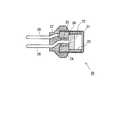
ここで、図1は本発明の技術を、生体に対して注射を行う注射器に適用した注射器1の断面図である。注射器1は、本発明に係る注射目的物質に相当する注射液を、注射対象となる生体内の領域(例えば、動物の皮膚構造体)に直接に送り届ける注射針を有していない無針注射器である。なお、本実施例では、注射目的物質を液体としているが、これには生体内に注射される物質の内容や形態を限定する意図はない。上述の通り、例えば皮膚構造体に対して注射すべき物質はその治療目的に応じて様々であるため、皮膚構造体に届けるべき成分が当該治療目的に適応している限りにおいては、溶解していても溶解していなくてもよく、また注射目的物質も、エネルギーにより注射器1から皮膚構造体に対して射出され得るものであれば、その具体的な形態は不問であり、液体、ゲル状等様々な形態が採用できる。 Here, FIG. 1 is a cross-sectional view of a
注射器1は、その本体としてハウジング2を有しており、その内部において先端部から後端部にかけてノズルホルダ5、ピストンホルダ3、点火器ホルダ12が一列に並べられている。そして、ハウジング2の後端部においてキャップ30が、ハウジング2の後方側面に設けられたネジ部と螺合することで、ノズルホルダ5、ピストンホルダ3、点火器ホルダ12に対して力を加え、これらの構成要素をハウジング2内に固定し、注射器1を使用可能状態とすることができる。具体的には後述するようにハウジング2の先端部に形成されている段部2cに対して、ノズルホルダ5、ピストンホルダ3、点火器ホルダ12をキャップ30によって挟持している。なお、本実施例において、「先端部」と称する場合は、後述するように注射液の射出方向(ピストン4の推進方向)における構成要素の端部を意味するものであり、一方で、「後端部」と称する場合は、先端部とは反対の側における構成要素の端部を意味するものである。 The
ここで、ハウジング2には、上記の通りノズルホルダ5、ピストンホルダ3、点火器ホルダ12を収容するための空間を画定する内孔2aを有している。更に、ハウジング2の先端部において、内孔2aとハウジング2の外部とを連通するように形成される貫通孔2bが設けられている。貫通孔2bと内孔2aの中心は同軸上に設けられ、貫通孔2bの内径は、内孔2aの内径よりも小さく設定されている。そのため、ハウジング2の先端部側の内部には、段部2cが形成されている。 Here, the
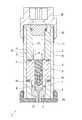
ここで、点火器ホルダ12に取り付けられる点火器20の例について、図2に基づいて説明する。点火器20は電気式の点火装置であり、表面が絶縁カバーで覆われたカップ21によって、点火薬22を配置するための空間が該カップ21内に画定される。そして、その空間に金属ヘッダ24が配置され、その上面に筒状のチャージホルダ23が設けられている。該チャージホルダ23によって点火薬22が保持される。この点火薬22の底部には、片方の導電ピン28と金属ヘッダ24を電気的に接続したブリッジワイヤ26が配線されている。なお、二本の導電ピン28は非電圧印加時には互いが絶縁状態となるように、絶縁体25を介して金属ヘッダ24に固定される。さらに、二本の導電ピン28が延出するカップ21の開放口側は、樹脂27によって導電ピン28間の絶縁性を良好に維持した状態で保護されている。 Here, the example of the
このように構成される点火器20においては、キャップ30において接続された電源部(不図示)によって二本の導電ピン28間に電圧印加されるとブリッジワイヤ26に電流が流れ、それにより点火薬22が燃焼する。なお、この電圧印加は、電源部のボタンをユーザが押下することで実現される。そして、電圧印加の結果、点火薬22の燃焼による燃焼生成物はチャージホルダ23の開口部から噴出されることになる。そこで、本発明においては、点火器20での点火薬22の燃焼生成物が、点火器ホルダ12の内部に形成された燃焼室11内に流れ込むように、点火器ホルダ12に対する点火器20の相対位置関係が設定されている。 In the
なお、注射器1において用いられる点火薬22として、好ましくは、ジルコニウムと過塩素酸カリウムを含む火薬(ZPP)、水素化チタンと過塩素酸カリウムを含む火薬(THPP)、チタンと過塩素酸カリウムを含む火薬(TiPP)、アルミニウムと過塩素酸カリウムを含む火薬(APP)、アルミニウムと酸化ビスマスを含む火薬(ABO)、アルミニウムと酸化モリブデンを含む火薬(AMO)、アルミニウムと酸化銅を含む火薬(ACO)、アルミニウムと酸化鉄を含む火薬(AFO)、もしくはこれらの火薬のうちの複数の組合せからなる火薬が挙げられる。これらの火薬は、点火直後の燃焼時には高温高圧のプラズマを発生させるが、常温となり燃焼生成物が凝縮すると気体成分を含まないために発生圧力が急激に低下する特性を示す。なお、これら以外の火薬を点火薬として用いても構わない。 The igniting
ここで、図1に示す燃焼室11内には何も配置されていないが、点火薬22の燃焼で生じる燃焼生成物によって燃焼しガスを発生させる公知のガス発生剤を、燃焼室11内に配置するようにしてもよい。仮に燃焼室11内にガス発生剤を配置させる場合、その一例としては、ニトロセルロース98質量%、ジフェニルアミン0.8質量%、硫酸カリウム1.2質量%からなるシングルベース無煙火薬が挙げられる。また、エアバッグ用ガス発生器やシートベルトプリテンショナ用ガス発生器に使用されている各種ガス発生剤を用いることも可能である。このようなガス発生剤の併用は、上記点火薬22のみの場合と異なり、燃焼時に発生した所定のガスは常温においても気体成分を含むため、発生圧力の低下率は小さい。さらに、当該ガス発生剤の燃焼時の燃焼完了時間は、上記点火薬22と比べて極めて長いが、燃焼室11内に配置されるときの該ガス発生剤の寸法や大きさ、形状、特に表面形状を調整することで、該ガス発生剤の燃焼完了時間を変化させることが可能である。このようにガス発生剤の量や形状、配置を調整することで、燃焼室11内での発生圧
力を適宜調整できる。Here, nothing is arranged in the
次に、金属製のピストンホルダ3には、図1に示す注射器1の使用前において、金属製のピストン4を保持する貫通孔31が形成されている。ピストンホルダ3は、ハウジング2の内孔2aの内径とほぼ一致する外径を有する胴部32と、胴部32より小さい外径を有する首部33を先端部側に有しており、貫通孔31は、胴部32の後端部側から首部33の先端部側までを貫通する孔である。そして、ピストン4は、この貫通孔31内を軸方向に沿って摺動可能となるように配置され、その一端(後端部側)が燃焼室11側に露出し、他端(先端部側)には封止部材4aが一体に取り付けられている。この封止部材4aは、ピストン4の摺動に伴って注射液が円滑に貫通孔14内を移動できるように、表面にシリコンオイルを薄く塗布したゴム製のものである。ピストン4や封止部材4aとピストンホルダ3内の貫通孔31との摩擦を低減するため、例えばフッ素ゴム製の封止部材を使用することが出来る。また貫通孔31表面にシリコン処理を行うことも出来る。 Next, a through
さらに、注射器1の先端部側でピストンホルダ3に隣接して、注射液を射出するためのノズル部6を保持するノズルホルダ5が配置されている。ノズルホルダ5は、ハウジング2の内孔2aの内径とほぼ一致する外径を有する胴部51と、胴部51より小さい外径であって、ハウジング2の貫通孔2bの内径とほぼ一致する外径を先端部側に有する首部52を有している。更に、ノズルホルダ5には、ノズル部6を収容するための空間を画定する内孔5aが形成されており、内孔5aは、その先端部側において、ノズル部6の先端部分が外部に露出した状態で保持されるように、ノズル部6の表面形状に合わせてテーパー部5bが形成されている。 Furthermore, a
一方で、ノズル部6は、ノズルホルダ5の内孔5aの内径とほぼ一致する外径を有するとともに、その先端部側には、ノズルホルダ5のテーパー部5bに対応するテーパー部が形成されることで、ノズルホルダ5内でのノズル部6の継続的な保持が可能とされる。ここで、ノズル部6には、注射器1から射出される注射液が最終的に流れる流路6aが形成され、流路6aは、注射器1の先端部側に開口する開口部6bを有する。更に、ノズル部6の中央部であって、図1に示す状態において、ピストン4に取り付けられた封止部材4aに対向する部位に、液溜りを形成可能な程度の大きさを有する凹部6cが形成され、凹部6cは流路6aと繋がっている。なお、当該凹部6cについては、後述する。 On the other hand, the
ノズル部6は、樹脂成形により大量生産が可能なものであり、注射液の射出ごとに新しいノズル部に交換可能であるように形成されている。この結果、ユーザは、注射液の注射を行う度に常に新しいノズル部6を使用でき、衛生的な注射が実現される。また、流路6aの形状や大きさ等は、注射器1から射出される注射液の、射出後の挙動を決定付ける要素である。したがって、ノズル部6が上記の通り交換可能に形成されることで、注射すべき注射液を目標とする生体内の領域に送り込むのに適した流路を有するノズル部6を選択でき、以て当該注射液の射出を好適に実現することが可能となる。 The
上記までのように、ハウジング2内において、ノズル部6およびノズルホルダ5、ピストン4およびピストンホルダ3、点火器ホルダ12が配置されると、図1に示す注射器1の使用前の状態では、ピストン4に取り付けられた封止部材4aと、ノズル部6の凹部6cとの間に、注射液を収容可能な収容空間13が形成される。図1の注射器1では、注射液は、注射器1が組み立てられる際に収容空間13に装填されることになる。そして、後述するように、その装填された注射液は、点火器20での点火薬22の燃焼によって生じるエネルギーで加圧されることでノズル部6の開口部6bから射出されることになる。 As described above, when the
ここで、注射器1への各構成要素の組み立て順序について、図1および図3に基づいて説明する。先ず、ハウジング2の後端部側からノズル部6を保持した状態のノズルホルダ
5を挿入する。このとき、ノズル部6内の凹部6cには、注射液が装填された状態となっている。なお、図3においては、各構成要素の存在を把握しやすいように、ノズルホルダ5とノズル部6は、分離された状態で示されている。このとき、ノズルホルダ5の胴部51と首部52とで形成される段状部分が、ハウジング2の段部2cに突き当たるまで、ノズルホルダ5をハウジング2内に挿入する。当該段状部分が段部2cに突き当たった状態で、ノズルホルダ5に保持されているノズル部6の開口部6bが、ハウジング2の先端部側に露呈した状態となる。Here, the assembly order of each component to the
次に、ハウジング2の後端部側から、ピストン4を貫通孔31に保持した状態のピストンホルダ3を挿入する。なお、図3においては、各構成要素の存在を把握しやすいように、ピストンホルダ3とピストン4は、分離された状態で示されている。このとき、ピストンホルダ3の首部33がノズルホルダ5の内孔5a内に挿入し、ピストンホルダ3の胴部32と首部33とで形成される段状部分が、ノズルホルダ5の後端部に突き当たるまで、ピストンホルダ3をハウジング2内に挿入する。当該段状部分がノズルホルダ5の後端部に突き当たった状態で、ピストン4に取り付けられた封止部材4aと、ノズル部6の凹部6cとの間に、収容空間13が形成されることになる。なお、凹部6cの内径は、貫通孔31の内径と一致しており、ピストン4(もしくはピストン4に取り付けられた封止部材4a)は、凹部6cの内部にまで推進可能であり、封止部材4aが凹部6cの底面(先端部側の内壁面)に接触したとき、収容空間13の体積は、概ね零となる。 Next, the
次に、ハウジング2の後端部側から、点火器ホルダ12を挿入する。なお、上記の通り、点火器ホルダ12内には、点火器20によって生成される燃焼生成物が放出される燃焼室11の密封性を高めるために、ピストンホルダ3の後端部面と点火器ホルダ12の先端部面との間にOリング9が配置されている。ここで、点火器20による燃焼エネルギーをピストン4に効率的に伝えるために、燃焼室11の内径(φA)は、ピストン4の外径(もしくは、貫通孔31の内径)(φB)よりも若干大きく設計されている。そのため、ピストンホルダ3の後端部面が燃焼室11に露出し、点火器20からの燃焼エネルギーによる圧力を受け得る受圧面34が存在することとなる。 Next, the
点火器ホルダ12の挿入後は、点火器20が点火器ホルダ12に配置され、その後にキャップ30がハウジング2側に結合されることで、注射器1の組み立てが完了する。 After the
このように構成される注射器1では、点火器20に対して電源部が接続され、電源部からの電流によって点火器20が作動する。すると点火薬22の燃焼によって、燃焼室11内に燃焼生成物が充満し、その圧力を注射液の射出のためのエネルギーとしてピストン4に伝える。エネルギーを受けてピストン4は貫通孔31を推進していき、収容空間13に収容されている注射液に圧力を加えていくことで、ノズル部6の流路6aを経て注射対象物に向かって注射液が射出されることになる。射出された注射液には圧力が掛けられているため、注射対象物の表面を貫通し、その内部に注射液が到達することで、注射器1における注射の目的を果たすことが可能となる。 In the
ここで、ピストンホルダ3の後端部面においては、受圧面34が形成されていることから、注射液の射出時に、点火器20によって生じたエネルギーは、ピストンホルダ3を注射器1の先端部側に押し出す力として作用する。このとき、仮に、ピストンホルダ3が、ノズルホルダ5に保持された状態になっているノズル部6に接触していると、受圧面34が受けたエネルギーが不必要にノズル部6にまで伝わり、その結果、ノズル部6の変形、破損を引き起こし得る。そこで、この点を踏まえ、本実施例に係る注射器1では、図1に示す状態において、ピストンホルダ3の首部33の先端部面と、ノズルホルダ5に保持された状態にあるノズル部6の後端部面とが直接に接触しない非接触状態が、形成されている。当該非接触状態においては、首部33の先端部面とノズル部6の後端部面との間に所
定の距離Δdが確保され、当該距離Δdは、受圧面34が燃焼エネルギーを受けたときに生じ得るピストンホルダ3の微小な変形においても、首部33の先端部面とノズル部6の後端部面との非接触状態を維持し得る程度の値とされる。したがって、注射器1においては、点火器20での燃焼エネルギーの発生の前後において、首部33の先端部面とノズル部6の後端部面との非接触状態は維持されることになる。例えばこのΔdは0.1mmに設定することが出来る。Here, since the
なお、図1に示す状態では、上記非接触状態を形成する空間(首部33の先端部面とノズル部6の後端部面との間の距離Δdによる空間であり、以降では「隔離空間」と称する)8には、弾性部材7が配置されている。弾性部材7は、ピストンホルダ3とノズル部6によって挟まれた状態となっているため、上記のピストンホルダ3の微小な移動が生じた場合であっても、弾性部材7の存在によりピストンホルダ3がノズル部6に直接に接触するのを確実に回避でき、また弾性部材7の弾性力により、点火器20での燃焼エネルギーの発生時の衝撃を効果的に減衰することができる。なお、本発明に係る注射器の効果を得るためには、当該弾性部材7は必ずしも必要ではなく、上記隔離空間の存在により非接触状態が維持されるのであれば弾性部材7の配置を省略してもよい。 In the state shown in FIG. 1, a space that forms the non-contact state (a space defined by a distance Δd between the front end surface of the
このように首部33の先端部面とノズル部6の後端部面とを、点火器20での燃焼エネルギーの発生の前後において、すなわち、注射液の射出の前後において非触状態が維持可能となるように注射器1が設計されることで、ノズル部6に不必要に外力が掛かることで生じるノズル部6の変形、破損等を回避することができる。特に、ノズル部6が生産性の観点等から樹脂等の比較的強度が低い素材で形成されている場合には、ノズル部6内の流路が外力により変形等しやすいため、適切な注射液の射出を担保するという観点からも、本実施例に係る注射器1の構造は極めて有用なものと考えられる。 In this way, the front end surface of the
<変形例>
図1に示す注射器1においては、ピストンホルダ3の後端部面に受圧面34が形成されているが、このような受圧面が形成されない場合であっても、すなわち、燃焼室11の内径(φA)がピストン4の外径(φB)よりも小さい場合であっても、上述した「首部33の先端部面とノズル部6の後端部面との非接触状態を維持する」構成は、有用である。点火器20による燃焼エネルギーを受けてピストン4が貫通孔31内を先端部側に推進する際、ピストンホルダ3は、ピストン4から摩擦力を受け、その力が、同じようにピストンホルダ3を先端部側に押し出す力として作用するからである。このようなケースにおいても、「首部33の先端部面とノズル部6の後端部面との非接触状態を維持する」構成が採用されることで、ノズル部6の変形等を回避し、適切な注射液の射出を担保することが可能となる。<Modification>
In the
図4に、本発明の第二の実施例に係る注射器1の概略構成を示す。「首部33の先端部面とノズル部6の後端部面との非接触状態」については、図1に示す注射器1では、ピストンホルダ3の胴部32と首部33とで形成される段状部分が、ノズルホルダ5の後端部に突き当たることで、形成および維持される。しかしながら、本実施例においては、それとは異なる構成により、上記非接触状態の形成および維持が実現される。 FIG. 4 shows a schematic configuration of the
具体的には、図4に示す注射器1に示すように、ハウジング2の内孔2aにおいて、図1に示す段部2cは設けられず、内孔2aは後端部側から先端部側まで一定の内径を有する貫通孔として形成される。そして、内孔2aの途中に、ハウジング2内に突出する環状の突部2dが設けられている。当該突部2dは、後述するようにノズルホルダ5の後端部面およびピストンホルダ3の胴部32の先端部面と面接触するために、先端部側および後端部側がそれぞれ平面状に形成され、且つ所定の厚みを有する板状に形成されている。 Specifically, as shown in the
本実施例に係る注射器1においては、このように構成されるハウジング2に対して、ノズル部6を保持した状態のノズルホルダ5が、該ノズルホルダ5の後端部面が突部2dに接触するまで、先端部側から挿入される。挿入されたノズルホルダ5は、先端部側からハウジング2に対して螺合されるキャップ10によって、ハウジング2内に固定される。一方で、ハウジング2に対して、ピストン4を保持した状態のピストンホルダ3が、該ピストンホルダ3の胴部32の先端部面が突部2dに接触するまで、後端部側から挿入され、その後、更に点火器ホルダ12がハウジング2内に挿入され、点火器20、キャップ30が取り付けられる。 In the
このように構成される注射器1においては、ピストンホルダ3の胴部32と首部33とで形成される段状部分は、ノズルホルダ5に直接に突き当たった状態とはならないが、ノズルホルダ5とピストンホルダ3が突部2dに接触した状態では、ピストンホルダ3の首部33が、ノズルホルダ5の内孔5aに挿入された状態となり、且つ、首部33の先端部面とノズル部6の後端部面との間には、上記の「非接触状態」が形成されることになる。したがって、点火器20による燃焼エネルギー発生の前後にわたって、ノズル部6に不必要な力が掛かるのを抑制することが可能となる。なお、図4では突部dはハウジング2に対して一体に形成されているが、例えば突部2dをハウジング2とは別体の金属ワッシャ状とし、配置することが出来る。この場合では、図1に示すようなハウジング2の後端側から各構成部品を挿入・組立する注射器にも適用可能である。 In the
<その他の実施例>
本発明に係る注射器1によれば、上述した注射液を皮膚構造体に注射する場合以外にも、例えば、再生医療の分野において、注射対象となる細胞や足場組織・スキャフォールドに培養細胞、幹細胞等を播種することが可能となる。例えば、特開2008−206477号公報に示すように、移植される部位及び再細胞化の目的に応じて当業者が適宜決定し得る細胞、例えば、内皮細胞、内皮前駆細胞、骨髄細胞、前骨芽細胞、軟骨細胞、繊維芽細胞、皮膚細胞、筋肉細胞、肝臓細胞、腎臓細胞、腸管細胞、幹細胞、その他再生医療の分野で考慮されるあらゆる細胞を、注射器1により注射することが可能である。<Other examples>
According to the
さらには、特表2007−525192号公報に記載されているような、細胞や足場組織・スキャフォールド等へのDNA等の送達にも、本発明に係る注射器1を使用することができる。この場合、針を用いて送達する場合と比較して、本発明に係る注射器1を使用した方が、細胞や足場組織・スキャフォールド等自体への影響を抑制できるためより好ましいと言える。 Furthermore, the
さらには、各種遺伝子、癌抑制細胞、脂質エンベロープ等を直接目的とする組織に送達させたり、病原体に対する免疫を高めるために抗原遺伝子を投与したりする場合にも、本発明に係る注射器1は好適に使用される。その他、各種疾病治療の分野(特表2008−508881号公報、特表2010−503616号公報等に記載の分野)、免疫医療分野(特表2005−523679号公報等に記載の分野)等にも、当該注射器1は使用することができ、その使用可能な分野は意図的には限定されない。 Furthermore, the
1・・・・注射器
2・・・・ハウジング
2a・・・・内孔
2b・・・・貫通孔
2c・・・・段部
2d・・・・突部
3・・・・ピストンホルダ
4・・・・ピストン
4a・・・・封止部材
5・・・・ノズルホルダ
5a・・・・内孔
5b・・・・テーパー部
6・・・・ノズル部
6a・・・・流路
6b・・・・開口部
6c・・・・凹部
7・・・・弾性部材
8・・・・隔離空間
9・・・・Oリング
10・・・・キャップ
11・・・・燃焼室
12・・・・点火器ホルダ
13・・・・収容空間
20・・・・点火器
31・・・・貫通孔
32・・・・胴部
33・・・・首部
34・・・・受圧面
51・・・・胴部
52・・・・首部DESCRIPTION OF
Claims (4)
Translated fromJapaneseハウジングと、
前記注射目的物質を射出するためのエネルギーを発生させる駆動部と、
前記駆動部によって発生されたエネルギーによって推進するピストンの進路を画定するピストンホルダと、
前記ピストンにより加圧された前記注射目的物質が流れる流路を含み、該流路の開口端から注射対象領域に対して該注射目的物質を射出するノズル部と、
前記ノズル部を保持した状態で前記ハウジングに固定されるノズルホルダと、を備え、
前記駆動部によるエネルギー発生が行われる前において、前記ピストンホルダ内の前記進路に保持されている前記ピストンの、該ピストンの進行方向側に、前記注射目的物質が収容される収容空間が形成され、
前記ピストンホルダは、前記ピストンの進行方向において前記ノズル部と直接に接触しない非接触状態で前記ハウジング内に固定され、前記駆動部によるエネルギー発生が行われる段階であっても、該非接触状態が維持され、
前記ピストンホルダの先端部と前記ノズル部の後端部との間に、弾性部材が挟まれて配置される、
注射器。A syringe for injecting an injection target substance into an injection target area,
A housing;
A drive unit for generating energy for injecting the injection target substance;
A piston holder that defines a path of a piston that is propelled by energy generated by the drive;
A flow path through which the injection target substance pressurized by the piston flows, and a nozzle portion for injecting the injection target substance from the open end of the flow path to the injection target region;
A nozzle holder fixed to the housing in a state where the nozzle portion is held,
Before the energy generation by the drive unit is performed, an accommodation space for accommodating the injection target substance is formed on the piston in the traveling direction side of the piston held in the path in the piston holder,
The piston holder is fixed in the housing in a non-contact state where the piston holder is not in direct contact with the nozzle portion in the traveling direction of the piston, and the non-contact state is maintained even when energy is generated by the drive unit.And
An elastic member is disposed between the front end portion of the piston holder and the rear end portion of the nozzle portion.
Syringe.
請求項1に記載の注射器。The piston holder contacts the nozzle holder in the direction of travel of the piston and is fixed in the housing, thereby forming the non-contact state between the piston holder and the nozzle portion.
The syringe according to claim 1.
請求項1又は請求項2に記載の注射器。The nozzle part is formed of resin.
The syringe according to claim 1 or claim 2.
前記ピストンホルダは、該ピストンホルダの後端部の一部が前記燃焼室に露出された状態で、前記ハウジング内に固定される、
請求項1から請求項3の何れか1項に記載の注射器。The drive unit has a combustion chamber in which explosives or a gas generating agent burns by an applied voltage from a power supply unit,
The piston holder is fixed in the housing in a state where a part of a rear end portion of the piston holder is exposed to the combustion chamber.
The syringe according to any one of claims 1 to 3.
Priority Applications (1)
| Application Number | Priority Date | Filing Date | Title |
|---|---|---|---|
| JP2012258706AJP6116874B2 (en) | 2012-11-27 | 2012-11-27 | Syringe |
Applications Claiming Priority (1)
| Application Number | Priority Date | Filing Date | Title |
|---|---|---|---|
| JP2012258706AJP6116874B2 (en) | 2012-11-27 | 2012-11-27 | Syringe |
Related Child Applications (1)
| Application Number | Title | Priority Date | Filing Date |
|---|---|---|---|
| JP2017056451ADivisionJP6336649B2 (en) | 2017-03-22 | 2017-03-22 | Syringe |
Publications (2)
| Publication Number | Publication Date |
|---|---|
| JP2014104112A JP2014104112A (en) | 2014-06-09 |
| JP6116874B2true JP6116874B2 (en) | 2017-04-19 |
Family
ID=51026110
Family Applications (1)
| Application Number | Title | Priority Date | Filing Date |
|---|---|---|---|
| JP2012258706AActiveJP6116874B2 (en) | 2012-11-27 | 2012-11-27 | Syringe |
Country Status (1)
| Country | Link |
|---|---|
| JP (1) | JP6116874B2 (en) |
Families Citing this family (5)
| Publication number | Priority date | Publication date | Assignee | Title |
|---|---|---|---|---|
| JP2016049246A (en)* | 2014-08-29 | 2016-04-11 | 株式会社ダイセル | Needleless injector |
| JP6471029B2 (en) | 2015-04-10 | 2019-02-13 | 株式会社ダイセル | Syringe |
| EP3486935B1 (en) | 2016-06-17 | 2023-03-15 | Daicel Corporation | Actuator |
| CN108553748A (en)* | 2018-05-11 | 2018-09-21 | 江秀秀 | Internal various kinds of cell is implanted into instrument under B ultrasound monitoring |
| WO2020149152A1 (en)* | 2019-01-16 | 2020-07-23 | 株式会社ダイセル | Needleless syringe |
Family Cites Families (3)
| Publication number | Priority date | Publication date | Assignee | Title |
|---|---|---|---|---|
| CN1651103A (en)* | 1998-07-27 | 2005-08-10 | 安塔雷斯药品公司 | Injection device |
| DE10029325A1 (en)* | 2000-06-20 | 2002-01-03 | Peter Lell | Needle-free injection device with pyrotechnic drive |
| JP5628698B2 (en)* | 2011-02-04 | 2014-11-19 | 株式会社ダイセル | Needleless syringe nozzle and needleless syringe |
- 2012
- 2012-11-27JPJP2012258706Apatent/JP6116874B2/enactiveActive
Also Published As
| Publication number | Publication date |
|---|---|
| JP2014104112A (en) | 2014-06-09 |
Similar Documents
| Publication | Publication Date | Title |
|---|---|---|
| CN103442755B (en) | Needleless injector | |
| JP6116874B2 (en) | Syringe | |
| JP6471029B2 (en) | Syringe | |
| US20190184105A1 (en) | Needleless injector | |
| JP6678130B2 (en) | Syringe | |
| JP6926079B2 (en) | Syringe | |
| JP7034076B2 (en) | Dosing device | |
| JP6193558B2 (en) | Syringe | |
| EP3645082B1 (en) | Syringe | |
| JP6336649B2 (en) | Syringe | |
| JP5837392B2 (en) | Needleless syringe | |
| JP6612155B2 (en) | Syringe | |
| JP2019055331A (en) | Syringe | |
| JP7140442B2 (en) | needle-free syringe | |
| JPWO2020138474A1 (en) | Needleless syringe | |
| JPWO2020138476A1 (en) | Needleless syringe | |
| JP7012728B2 (en) | Injector | |
| JP6194345B2 (en) | Needleless syringe | |
| WO2021246061A1 (en) | Needleless syringe | |
| JP2013180121A (en) | Needleless syringe | |
| HK1240150A1 (en) | Needleless syringe | |
| HK1190651B (en) | Needleless syringe |
Legal Events
| Date | Code | Title | Description |
|---|---|---|---|
| A621 | Written request for application examination | Free format text:JAPANESE INTERMEDIATE CODE: A621 Effective date:20150909 | |
| A131 | Notification of reasons for refusal | Free format text:JAPANESE INTERMEDIATE CODE: A131 Effective date:20160719 | |
| A977 | Report on retrieval | Free format text:JAPANESE INTERMEDIATE CODE: A971007 Effective date:20160722 | |
| A521 | Request for written amendment filed | Free format text:JAPANESE INTERMEDIATE CODE: A523 Effective date:20160920 | |
| TRDD | Decision of grant or rejection written | ||
| A01 | Written decision to grant a patent or to grant a registration (utility model) | Free format text:JAPANESE INTERMEDIATE CODE: A01 Effective date:20170221 | |
| A61 | First payment of annual fees (during grant procedure) | Free format text:JAPANESE INTERMEDIATE CODE: A61 Effective date:20170322 | |
| R150 | Certificate of patent or registration of utility model | Ref document number:6116874 Country of ref document:JP Free format text:JAPANESE INTERMEDIATE CODE: R150 | |
| R250 | Receipt of annual fees | Free format text:JAPANESE INTERMEDIATE CODE: R250 |