JP6116821B2 - connector - Google Patents
connectorDownload PDFInfo
- Publication number
- JP6116821B2 JP6116821B2JP2012130629AJP2012130629AJP6116821B2JP 6116821 B2JP6116821 B2JP 6116821B2JP 2012130629 AJP2012130629 AJP 2012130629AJP 2012130629 AJP2012130629 AJP 2012130629AJP 6116821 B2JP6116821 B2JP 6116821B2
- Authority
- JP
- Japan
- Prior art keywords
- electric wire
- housing
- hook
- wire
- curved surface
- Prior art date
- Legal status (The legal status is an assumption and is not a legal conclusion. Google has not performed a legal analysis and makes no representation as to the accuracy of the status listed.)
- Active
Links
- 230000002093peripheral effectEffects0.000claimsdescription14
- 239000000945fillerSubstances0.000claimsdescription7
- 238000007789sealingMethods0.000claimsdescription7
- 230000004308accommodationEffects0.000description6
- 239000007788liquidSubstances0.000description6
- 229920001296polysiloxanePolymers0.000description6
- 238000005192partitionMethods0.000description5
- 239000000758substrateSubstances0.000description5
- 238000002788crimpingMethods0.000description4
- 239000002184metalSubstances0.000description4
- 238000003825pressingMethods0.000description3
- 229920003002synthetic resinPolymers0.000description3
- 239000000057synthetic resinSubstances0.000description3
- 238000005452bendingMethods0.000description2
- 238000010438heat treatmentMethods0.000description2
- 230000000694effectsEffects0.000description1
- 238000002347injectionMethods0.000description1
- 239000007924injectionSubstances0.000description1
- 238000009940knittingMethods0.000description1
- 239000007769metal materialSubstances0.000description1
- 238000000034methodMethods0.000description1
- 238000012986modificationMethods0.000description1
- 230000004048modificationEffects0.000description1
- 238000012856packingMethods0.000description1
- 230000000149penetrating effectEffects0.000description1
- 229920001187thermosetting polymerPolymers0.000description1
- XLYOFNOQVPJJNP-UHFFFAOYSA-NwaterSubstancesOXLYOFNOQVPJJNP-UHFFFAOYSA-N0.000description1
Images


Classifications
- H—ELECTRICITY
- H01—ELECTRIC ELEMENTS
- H01R—ELECTRICALLY-CONDUCTIVE CONNECTIONS; STRUCTURAL ASSOCIATIONS OF A PLURALITY OF MUTUALLY-INSULATED ELECTRICAL CONNECTING ELEMENTS; COUPLING DEVICES; CURRENT COLLECTORS
- H01R13/00—Details of coupling devices of the kinds covered by groups H01R12/70 or H01R24/00 - H01R33/00
- H01R13/46—Bases; Cases
- H01R13/502—Bases; Cases composed of different pieces
- H01R13/506—Bases; Cases composed of different pieces assembled by snap action of the parts
- H—ELECTRICITY
- H01—ELECTRIC ELEMENTS
- H01R—ELECTRICALLY-CONDUCTIVE CONNECTIONS; STRUCTURAL ASSOCIATIONS OF A PLURALITY OF MUTUALLY-INSULATED ELECTRICAL CONNECTING ELEMENTS; COUPLING DEVICES; CURRENT COLLECTORS
- H01R13/00—Details of coupling devices of the kinds covered by groups H01R12/70 or H01R24/00 - H01R33/00
- H01R13/46—Bases; Cases
- H01R13/52—Dustproof, splashproof, drip-proof, waterproof, or flameproof cases
- H01R13/5202—Sealing means between parts of housing or between housing part and a wall, e.g. sealing rings
- H—ELECTRICITY
- H01—ELECTRIC ELEMENTS
- H01R—ELECTRICALLY-CONDUCTIVE CONNECTIONS; STRUCTURAL ASSOCIATIONS OF A PLURALITY OF MUTUALLY-INSULATED ELECTRICAL CONNECTING ELEMENTS; COUPLING DEVICES; CURRENT COLLECTORS
- H01R13/00—Details of coupling devices of the kinds covered by groups H01R12/70 or H01R24/00 - H01R33/00
- H01R13/46—Bases; Cases
- H01R13/52—Dustproof, splashproof, drip-proof, waterproof, or flameproof cases
- H01R13/5205—Sealing means between cable and housing, e.g. grommet
- H—ELECTRICITY
- H01—ELECTRIC ELEMENTS
- H01R—ELECTRICALLY-CONDUCTIVE CONNECTIONS; STRUCTURAL ASSOCIATIONS OF A PLURALITY OF MUTUALLY-INSULATED ELECTRICAL CONNECTING ELEMENTS; COUPLING DEVICES; CURRENT COLLECTORS
- H01R13/00—Details of coupling devices of the kinds covered by groups H01R12/70 or H01R24/00 - H01R33/00
- H01R13/58—Means for relieving strain on wire connection, e.g. cord grip, for avoiding loosening of connections between wires and terminals within a coupling device terminating a cable
- H01R13/582—Means for relieving strain on wire connection, e.g. cord grip, for avoiding loosening of connections between wires and terminals within a coupling device terminating a cable the cable being clamped between assembled parts of the housing
- H—ELECTRICITY
- H01—ELECTRIC ELEMENTS
- H01R—ELECTRICALLY-CONDUCTIVE CONNECTIONS; STRUCTURAL ASSOCIATIONS OF A PLURALITY OF MUTUALLY-INSULATED ELECTRICAL CONNECTING ELEMENTS; COUPLING DEVICES; CURRENT COLLECTORS
- H01R2105/00—Three poles
- H—ELECTRICITY
- H01—ELECTRIC ELEMENTS
- H01R—ELECTRICALLY-CONDUCTIVE CONNECTIONS; STRUCTURAL ASSOCIATIONS OF A PLURALITY OF MUTUALLY-INSULATED ELECTRICAL CONNECTING ELEMENTS; COUPLING DEVICES; CURRENT COLLECTORS
- H01R2201/00—Connectors or connections adapted for particular applications
- H01R2201/26—Connectors or connections adapted for particular applications for vehicles
Landscapes
- Connector Housings Or Holding Contact Members (AREA)
Description
Translated fromJapanese本発明は、電線に接続される端子金具と、該端子金具及び電線を収容する端子収容室を有するハウジングと、を備えたコネクタに関する。 The present invention relates to a connector including a terminal fitting connected to an electric wire and a housing having a terminal accommodating chamber for accommodating the terminal fitting and the electric wire.
移動体としての自動車には、多種多様な電子機器が搭載されている。この電子機器に電力や制御信号などを伝えるためにワイヤハーネスが用いられる。ワイヤハーネスは、複数の電線とコネクタとを備えている。 A wide variety of electronic devices are mounted on automobiles as moving bodies. A wire harness is used to transmit electric power and control signals to the electronic device. The wire harness includes a plurality of electric wires and connectors.
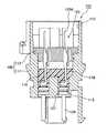
コネクタは、図7に示すように、コネクタハウジング100と雄端子金具125とを備えて構成されている。コネクタハウジング100は、合成樹脂製のハウジング本体111と同じく合成樹脂製の位置決め部材112とからなる。ハウジング本体111内には、上から順に嵌合部113、充填空間114、及びゴム栓嵌合孔115が形成されている。嵌合部113は、充填空間114に対して上方に連なるとともにコネクタハウジング100の上面に開口された筒状をなしている。ゴム栓嵌合孔115は、各雄端子金具125と対応するように個別に複数形成され、充填空間114とコネクタハウジング100の下端面との間に貫通されている。位置決め部材112の周縁部には、部分的に切欠することにより充填空間114内に連通し、充填空間114内に充填剤を注入するための注入口(図示しない)が形成されている。 As shown in FIG. 7, the connector includes a
ゴム栓嵌合孔115は円形断面とされ、その内径が、ゴム栓127の外径よりも少し小さい寸法に設定されている。 The rubber
上述した構成の従来のコネクタ101は、位置決め部材112がコネクタハウジング100内に収容された状態で、電線126に接続された雄端子金具125の雄タブ125A側の先端を、ゴム栓嵌合孔115側からコネクタハウジング100内に圧入して、ゴム栓127をゴム栓嵌合孔115内に位置付ける。ゴム栓127の外周は、ゴム栓嵌合孔115の内周に弾性的に密着した状態で嵌合される。次に、ゴム栓嵌合孔115を下向きにして、注入口から充填空間114に充填剤を注入する。この充填剤により、ゴム栓嵌合孔115とゴム栓127との嵌合面が充填剤116で塞がれてゴム栓嵌合孔115からコネクタハウジング100の内部への浸水が防止されていた(例えば、特許文献1参照)。 In the
しかしながら、上述した従来のコネクタ101では、ゴム栓127をゴム栓嵌合孔115内に圧入して、ゴム栓嵌合孔115の内周面にゴム栓127の外周面を弾性的に密着させていたので、ゴム栓127をゴム栓嵌合孔115内に圧入する際にゴム栓127が切れてしまうなどして作業性が悪かった。このため、ゴム栓127をゴム栓嵌合孔115内に圧入する際の作業性を考慮して、ゴム栓嵌合孔115の内径寸法を、ゴム栓127の外径寸法よりも少ししか小さく形成することができず、電線屈曲時に、ゴム栓127とゴム栓嵌合孔115と間に隙間ができるなどして、ゴム栓127及びゴム栓嵌合孔115の密着性が低下して、防水性を確保することができなかった。即ち、ゴム栓127及びゴム栓嵌合孔115の密着性を高めるために、ゴム栓嵌合孔115の内径寸法を、ゴム栓127の外径寸法よりもさらに小さく形成すればよいが、そうすると、ゴム栓127をゴム栓嵌合孔115内に挿入する際の作業性が悪くなる問題があった。電線屈曲時におけるゴム栓127及びゴム栓嵌合孔115の密着性の確保、及びゴム栓127のゴム栓嵌合孔115内への挿入し易さを両立させることが困難であった。 However, in the
本発明の目的は、電線屈曲時における防水性の向上を図ったコネクタを提供することにある。 The objective of this invention is providing the connector which aimed at the waterproof improvement at the time of an electric wire bending.
請求項1に記載の本発明は、電線の端末に接続される端子金具と、該端子金具及び前記電線を収容するハウジングと、を備えたコネクタであって、前記ハウジングに取り付けられる電線押さえ部材と、前記電線に外嵌されるリング状のシール部材と、を備え、前記ハウジングには、前記電線の外周面に沿う曲面を有する第1樋状部が設けられ、前記電線押さえ部材には、前記電線の外周面に沿う曲面を有する第2樋状部が設けられ、前記ハウジングの内部には、前記シール部材が、前記第1樋状部の前記曲面及び前記第2樋状部の前記曲面に密着した状態で挟んで保持され、前記第1樋状部及び前記第2樋状部には、それぞれの前記曲面に、前記シール部材が収容された状態で当該シール部材を前記ハウジングに対して前記電線の長手方向の所定位置に位置決めするための溝部が設けられ、前記シール部材が、前記溝部内に密着した状態で収容されていることを特徴とするコネクタである。The present invention according to
請求項2記載の本発明は、請求項1記載のコネクタにおいて、前記端子金具は、前記電線の端末に接続される電線接続部と、該電線接続部との間で曲げられるとともに、相手方の端子金具に接続される電気接触部と、で構成されていることを特徴とする。According to asecond aspect of the invention, the connector according to claim1 Symbol mounting, the terminal fitting includes a wire connection portion to be connected to a terminal of the wire, with bent between the electric wire connecting part, the other party And an electrical contact portion connected to the terminal fitting.
請求項3記載の本発明は、請求項1又は請求項2記載のコネクタにおいて、前記端子金具と前記電線との接続部分の周辺に、充填剤が充填されていることを特徴とする。According to athird aspect of the present invention, there is provided the connector according to the firstor second aspect , wherein a filler is filled around a connection portion between the terminal fitting and the electric wire.
請求項1記載の本発明によれば、ハウジングには、電線の外周面に沿う曲面を有する第1樋状部が設けられ、電線押さえ部材には、電線の外周面に沿う曲面を有する第2樋状部が設けられ、ハウジングの内部には、シール部材が、第1樋状部の曲面及び第2樋状部の曲面に密着した状態で挟んで保持されるから、従来のように、ゴム栓をゴム栓嵌合孔内に圧入する必要がなくなり、作業性の向上を図ることができる。また、作業性を考慮することなく、シール部材の外径寸法を、第1樋状部及び第2樋状部それぞれの曲面と密着するように設定できるから、電線屈曲時において、第1樋状部及び第2樋状部それぞれの曲面とシール部材との間に隙間が生じることがなくなって、防水性の向上を図ることができる。 According to the first aspect of the present invention, the housing is provided with the first hook-like portion having a curved surface along the outer peripheral surface of the electric wire, and the electric wire holding member has the second curved surface along the outer peripheral surface of the electric wire. A hook-shaped part is provided, and the seal member is held inside the housing while being in close contact with the curved surface of the first hook-shaped part and the curved surface of the second hook-shaped part. It is not necessary to press-fit the stopper into the rubber stopper fitting hole, and workability can be improved. In addition, the outer diameter dimension of the seal member can be set so as to be in close contact with the curved surfaces of the first and second hook-shaped parts without considering workability. A gap is not generated between the curved surface of each of the part and the second hook-like part and the seal member, and the waterproofness can be improved.
また、使用する電線を、電線径の異なる電線に変更した際においても、シール部材が弾性変形することで、電線の外周面と第1樋状部及び第2樋状部それぞれの曲面との間に隙間ができたとしても、それを吸収できるから、ハウジング及び電線押さえ部材を変更せずにそのまま利用することができる。このように、部品を汎用的に利用することができるから、電線径の異なる電線に対応した複数のハウジング及び電線押さえ部材を用意する必要がなくなり、部品点数の削減を図ることができる。Also, the wire used in when changing to a different wire of the wire diameter smaller, that sealing member is elastically deformed,between the outer surface and the first troughs and second troughs each curved surface of the wireEven if a gap is formed in the housing, it can be absorbed, and can be used as it is without changing the housing and the wire pressing member. Thus, since the components can be used for general purposes, it is not necessary to prepare a plurality of housings and wire holding members corresponding to wires having different wire diameters, and the number of components can be reduced.
また、シール部材が溝部内に収容されることにより、電線が引っ張られるなどして、シール部材に外力がかけられても、シール部材を電線の長手方向に位置決めし、シール部材を所定の位置に留めることができるから、より一層、防水性の向上を図ることができる。Further , when the sealing member is accommodated in the groove portion, even if an external force is applied to the sealing member by pulling the electric wire or the like, the sealing member is positioned in the longitudinal direction of the electric wire and the sealing member is set at a predetermined position. Since it can be fastened, the waterproof property can be further improved.
請求項2記載の本発明によれば、端子金具が、電線の端末に接続される電線接続部と、該電線接続部との間で曲げられるとともに、相手方の端子金具に接続される電気接触部と、で構成されているから、コネクタを組み立てる際に、端子金具に接続された電線と、電線押さえ部材とをハウジングの同じ方向から組み付けることとなり、よって、組立作業性の向上を図ることができる。According to this invention of
請求項3記載の本発明によれば、端子金具と電線との接続部分の周辺に、充填剤が充填されているから、端子金具と電線との接続部分の防水性(止水性)の向上を図ることができる。According to thethird aspect of the present invention, since the filler is filled around the connecting portion between the terminal fitting and the electric wire, the waterproofness (waterproofness) of the connecting portion between the terminal fitting and the electric wire is improved. Can be planned.
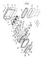
本発明の一実施の形態にかかるコネクタを、図1〜図6を参照して説明する。コネクタは、自動車などに配索されるワイヤハーネスを構成するものであり、図1、図2に示すように、ワイヤハーネスを構成する電線10の端末に取り付けられる3つの端子金具2と、該3つの端子金具2を収容する3つの端子収容室40を有するとともに、一方側、及び他方側に開口3a、3b(図2に示す)を有するハウジング3と、該ハウジング3の端部に取り付けられるリアホルダ(電線押さえ部材)5と、電線10に外嵌されるリング状のシールキャップ(シール部材)6と、ハウジング3の一方側の開口3aを塞ぐシールド体7と、ハウジング3の他方側の開口3bを塞ぐフロントホルダ8と、を備えている。 A connector according to an embodiment of the present invention will be described with reference to FIGS. The connector constitutes a wire harness that is routed in an automobile or the like. As shown in FIGS. 1 and 2, the three
ここで、図1中の矢印X方向は、端子収容室40が並ぶ方向を示し、矢印Y方向は、電線10の長手方向を示し、矢印Z方向は、矢印X方向と矢印Y方向との双方に直交する方向を示している。また、本明細書では、図1中の紙面方向の矢印Y方向の上方側を「上」と記すことがある。 Here, the arrow X direction in FIG. 1 indicates the direction in which the
端子金具2は、導電性の板金が折り曲げられることで得られるものである。また、端子金具2は、図3に示すように、電線10に接続される電線接続部21と、該電線接続部21に連なり、相手方の端子金具2に接続される電気接触部22と、を備えている。この端子金具2は、電線接続部21と電気接触部22との間で曲げられて、L字状に形成されている。 The
電線接続部21は、図3に示すように、電線10を表面上に位置付ける長方形状の基壁23と、該基壁23の幅方向の両端部から立設され電線10の芯線を圧着する一対の圧着片24と、を備えている。電線接続部21は、その端部が皮剥きされて芯線が露出した状態の断面丸形の電線10が基壁23上に載置された後、この電線10の芯線部分を基壁23に向かって押しつける方向に圧着片24が曲げられて、即ち圧着片24で電線10の芯線部分をかしめて電線10と電気的に接続される。 As shown in FIG. 3, the electric
ハウジング3は絶縁性の合成樹脂から構成されている。このハウジング3は、図4に示すように、略長方形状の底壁30と、該底壁30の矢印Z方向の一方側に設けられ、3つの端子金具2の電線接続部21の各々を収容する3つの端子収容室40などを有する第1収容部31と、該底壁30の矢印Z方向の他方側に設けられ、3つの端子金具2の電気接触部22を収容する第2収容部32と、を備えている。 The
底壁30には、シールド体7の係止孔7a(後述する)に係止される係止部30a(図1に示す)が設けられている。この係止部30aは、該底壁30の一方側の面において、第1収容部31よりも上方側に設けられている。 The
第1収容部31には、図4に示すように、一方側に開口3aを有する四角筒状に形成されている。この第1収容部30は底壁30の長手方向(矢印X方向)の両端部から立設された一対の側壁31Aと、該一対の側壁31Aを連結するとともに底壁30から立設された上壁31Bと、一対の側壁31A間に設けられ、第1収容部30を矢印X方向に3つの端子収容室40に仕切るとともに側壁31Aの矢印Y方向の寸法よりも短く形成された2つの仕切り板31Cと、底壁30と各仕切り板31Cとの双方に連なり上壁31Bと対向する2つ内壁31Dと、該各内壁31Dと対向するとともに底壁30の他方の縁から立設された下壁31Eと、端子収容室40から導出された電線10が載置される第1樋状部4Aと、を備えている。 As shown in FIG. 4, the first
一対の側壁31Aには、それぞれの外面にリアホルダ5の第1ロックアーム51(後述する)に係合する第1ロック突起32が設けられている。この第1ロック突起32の矢印Y方向の両側には、一対のリブ32aが設けられている。一対のリブ32a間には、第1ロックアーム51が進入される。 The pair of
また、第1収容部31には、3つの端子収容室40が設けられている。3つの端子収容室40は矢印X方向に沿って並んでいる。各端子収容室40は、矢印Z方向の一方側に開口40aと、上壁31Bと対向する位置に設けられて電線10を導出するための導出口40bと、を有して箱状に形成されている。この端子収容室40の開口40aは、前述した第1収容部31の開口3aの一部である。各端子収容室40は、端子金具2と、この端子金具2に接続された電線10との接続部分が収容される空間であり、底壁30、上壁31B、側壁31A及び仕切り板31C(又は一対の仕切り板31C)、及び内壁31Dで囲まれた空間である。各端子収容室40内には、端子金具2と電線10とが収容された状態で、加熱することで硬化する熱硬化型の液状シリコーン9が注入される。 In addition, the
この端子収容室40は、開口40aと対向する位置に設けられた長方形状の底面42は、ハウジング3の底壁30の一方側の面の一部である。この底面42には、ハウジング3の底壁30を貫通し、端子金具2の電気接触部22が挿通される貫通孔42a(図2に示す)が形成されている。 In the
第1樋状部4Aは、電線10の外周面に沿う曲面42を有して構成されている。この曲面42には、シールキャップ6を収容するための第1溝部43が形成されている。第1溝部43は、曲面42の周方向に沿って延在して形成されているとともに、その深さ寸法が、シールキャップ6の径方向の厚み寸法よりも小さくなるように形成されている。 4 A of 1st hook-shaped parts have the
第1樋状部4Aは、図3、図4などに示すように、その曲面42が、リアホルダ5に設けられた第2樋状部4B(後述する)の曲面44と互いに対向して組み合わされることで筒状の電線収容室41を形成する。各電線収容室41の内側には、シールキャップ6が、その全周に亘って第1樋状部4Aの曲面42及び第2樋状部4Bの曲面44に密着した状態で電線10が収容される。この電線収容室41は、その軸方向が矢印Y方向に直線状に延びていて、その径寸法が、電線10の外径寸法と略等しくなるように形成されている。 As shown in FIGS. 3, 4, and the like, the first bowl-shaped portion 4 </ b> A has a
各電線収容室41の幅寸法(矢印X方向)は、図4に示すように、各端子収容室40の幅寸法よりも小さく形成され、互いに隣り合う電線収容室41間には、リアホルダ5の第2ロックアーム52が進入するアーム収容室46が設けられている。このアーム収容室46の内面には、リアホルダ5の第2ロックアーム52が係合する第2ロック突起(図示しない)が設けられている。 As shown in FIG. 4, the width dimension of each electric
第2収容部32は、図3に示すように、第1収容部31の開口3aと反対側、即ち矢印Z方向の他方側に開口3bを有する筒状に形成されている。この第2収容部32は、底壁30の他方側の面から立設されている。また、第2収容部32の上端部には、フロントホルダ8の係合部82(後述する)に係合する係合孔32aが形成されている。 As shown in FIG. 3, the
リアホルダ5は、図3に示すように、長方形状の基板50と、該基板50の長手方向(矢印X方向)に間隔をあけて設けられているとともに、該基板50の矢印Z方向の他方側の表面から突出した3つの第2樋状部4Bと、基板50の長手方向の両端部から他方側に立設され、矢印X方向に弾性変形自在に形成された一対の第1ロックアーム51と、該基板50における3つの第2樋状部4B間から他方側に立設され、矢印Y方向に弾性変形自在に形成された2つの第2ロックアーム52と、を備えている。ロックアーム51、52は、矢印Xに沿って直線上に並ぶ位置に設けられている。 As shown in FIG. 3, the
第2樋状部4Bは、その内面が電線10の表面に重ねられる曲面44に形成され、矢印Y方向に直線状に延在している。第2樋状部4Bの曲面44には、シールキャップ6を収容するための第2溝部45が形成されている。第2溝部45は、曲面44の周方向に沿って延在して形成されているとともに、その深さ寸法が、シールキャップ6の径方向の厚み寸法よりも小さくなるように形成されている。 The second hook-shaped
シールド体7は、図3に示すように、電線10の他端側を覆う筒状の編組線71と、該編組線71の端部に取り付けられるととともに第1収容部31の開口3aを塞ぐ板状のシールドシェル72と、編組線71とシールドシェル72とを互いに取り付けるシールドリング73と、を備えている。 As shown in FIG. 3, the
編組線71は、例えば、導電性の金属材料等からなる素線が編まれるなどして形成されている。また、編組線71には、その内径が拡げられてシールドシェル72の電線通し部79(後述する)の外周面を覆う大径部71aが設けられている。 The
シールドシェル72は導電性の金属から構成されている。シールドシェル72は、図2、図3に示すように、第1収容部31の開口3aを塞ぐ長方形状の基壁74と、該基壁74の長手方向(矢印X方向)の両端部からハウジング3側に立設された一対の側壁75と、該一対の側壁75を連結するとともに、基壁74の幅方向(矢印Y方向)に端部から立設された第1上壁76と、該第1上壁76の端部に連なり基壁74と平行な立設壁77と、該立設壁77の縁から立設され、第1上壁76と平行な第2上壁78と、第1上壁76と対向する位置に設けられ、内側に電線10の他端側を挿通させる筒状の電線通し部79と、を備えている。立設壁77には、該立設壁77を貫通した係止孔7aが形成されている。この係止孔7aはハウジング3の係止部30aに係止される。 The
フロントホルダ8は、図3に示すように、第2収容部32の開口3bを塞ぐ楕円形状の板部80と、該板部80の周縁から立設された筒状の周板81と、を備えている。板部80には、端子金具2の電気接触部22を挿通させる貫通孔80aが形成されている。周板81の内面には、第2収容部32の係合孔32a内に進入される係合部82(図2に示す)が設けられている。 As shown in FIG. 3, the
続いて、上述したコネクタ1の組み立て手順について図3、図5を参照して説明する。まず、予め電線10を内側に挿通させたシールド体7の編組線71の大径部71aをシールドシェル72の電線通し部79に被せ、シールドリング73を用いて編組線71をシールドシェル72に取り付け、端子金具2を電線通し部79の内側に潜らせておく。 Then, the assembly procedure of the
電線10にシールキャップ6を外嵌し弾性的に密着させ、そして、シールキャップ6よりも一端部側で電線10と端子金具2とを接続する。次に、端子金具2の電気接触部22を、端子収容室40の貫通孔42a内に挿通し、端子金具2を端子収容室40内に収容し、端子収容室40の導出口40bから各電線10を導出する。シールキャップ6を第1溝部43内に収容し、電線10を第1樋状部4Aの曲面42上に載置する。 The
図5に示すように、リアホルダ5を、その第2樋状部4Bの曲面44が、第1樋状部4Aの曲面42と対向するように近付ける。第1ロックアーム51を第1収容部31の第1ロック突起32に係合し、第2ロックアーム52を第1収容部31のアーム収容室46内に進入させるとともに第2ロック突起に係合する。第2樋状部4Bの第2溝部45内にシールキャップ6が収容され、第1樋状部4Aと第2樋状部4Bとが組み合わされて筒状の電線収容室41(図2に示す)が形成される。こうして、リアホルダ5をハウジング3に取り付ける。第1溝部43及び第2溝部45内にシールキャップ6が収容された状態で、シールキャップ6が第1樋状部4Aと第2樋状部4Bとの間に挟んで保持されるから、第1溝部43及び第2溝部45それぞれの内面(即ち曲面42、44)とシールキャップ6とが全周に亘って弾性的に密着される。また、リアホルダ5がハウジング3に取り付けられることによって、端子収容室40の導出口40bと電線10との隙間が塞がれる。 As shown in FIG. 5, the
次に、端子収容室40の開口4aから液状シリコーン9を端子収容室4内に注入する。また、リアホルダ5が設けられていることにより、端子収容室40の導出口40bと電線10との隙間が塞がれるので、液状シリコーン9が端子収容室40の外側に漏れるのを防止できる。こうして、端子収容室40内に液状シリコーン9が充填される。この後、ヒータなどで加熱することで端子収容室40内の液状シリコーン9を硬化させる。 Next, the
次に、編組線71が取り付けられたシールドシェル72を第1収容部31の開口3aを塞ぐように該第1収容部31に近付け、第1収容部31の係止部30aが係止孔7aに係止し、シールド体7を第1収容部31に取り付ける。シールド体7は電線10を電気的にシールドする。最後に、フロントホルダ8を、板部80を第2収容部32の開口3bを覆うように近付け、係合部82を第2収容部32の係合孔32aに係合し、パッキン83を介して第2収容部32に取り付ける。こうしてコネクタ1を組み立てる。 Next, the
このようなコネクタ1は、図6に示すように、電線10に外嵌されたシールキャップ6が、第1樋状部4Aと第2樋状部4Bとの間に挟まれて、シールキャップ6が、これらの曲面42、44との間に密着した状態で保持されるから、作業性の向上を図ることができる。よって、シールキャップ6の外径寸法を、第1樋状部4A及び第2樋状部4Bそれぞれの曲面42、44と確実に密着するように設定できるから、電線屈曲時において、第1樋状部4A及び第2樋状部4Bそれぞれの曲面42、44とシールキャップ6との間に隙間が生じることがなくなって、防水性の向上を図ることができる。 As shown in FIG. 6, such a
また、コネクタ1にはシールド体7が設けられているので、電線10から編組線71の外部に電気的なノイズが漏洩するのを規制することができるとともに、端子収容室40内に液状シリコーン9が充填されているので、端子金具2と電線10との接続部分の防水(止水)性も発揮することができる。 Further, since the
また、使用する電線10を、電線径の異なる電線に変更した際においても、シールキャップ6が弾性変形することで、電線10の外周面と第1樋状部4A及び第2樋状部4Bそれぞれの曲面42、44との間に隙間ができたとしても、それを吸収できるから、ハウジング3及びリアホルダ5を変更せずに利用することができる。このように、部品を汎用的に利用することができるから、電線径の異なる電線に対応した複数のハウジング3及びリアホルダ5を用意する必要がなくなり、部品点数の削減を図ることができる。Further, even when the
また、前述した実施形態は本発明の代表的な形態を示したに過ぎず、本発明は、実施形態に限定されるものではない。即ち、本発明の骨子を逸脱しない範囲で種々変形して実施することができる。 Further, the above-described embodiments are merely representative forms of the present invention, and the present invention is not limited to the embodiments. That is, various modifications can be made without departing from the scope of the present invention.
1 コネクタ
2 端子金具
3 ハウジング
5 リアホルダ(電線押さえ部材)
6 シールキャップ(シール部材)
4A 第1樋状部
4B 第2樋状部
42、44 曲面
43 第1溝部(溝部)
45 第2溝部(溝部)1
6 Seal cap (seal member)
4A 1st hook-
45 Second groove (groove)
Claims (3)
Translated fromJapanese該端子金具及び前記電線を収容するハウジングと、を備えたコネクタであって、
前記ハウジングに取り付けられる電線押さえ部材と、
前記電線に外嵌されるリング状のシール部材と、を備え、
前記ハウジングには、前記電線の外周面に沿う曲面を有する第1樋状部が設けられ、
前記電線押さえ部材には、前記電線の外周面に沿う曲面を有する第2樋状部が設けられ、
前記ハウジングの内部には、前記シール部材が、前記第1樋状部の前記曲面及び前記第2樋状部の前記曲面に密着した状態で挟んで保持され、
前記第1樋状部及び前記第2樋状部には、それぞれの前記曲面に、前記シール部材が収容された状態で当該シール部材を前記ハウジングに対して前記電線の長手方向の所定位置に位置決めするための溝部が設けられ、
前記シール部材が、前記溝部内に密着した状態で収容されていることを特徴とするコネクタ。A terminal fitting connected to the end of the wire;
A connector for housing the terminal fitting and the electric wire,
An electric wire holding member attached to the housing;
A ring-shaped sealing member that is externally fitted to the electric wire,
The housing is provided with a first hook-like portion having a curved surface along the outer peripheral surface of the electric wire,
The electric wire holding member is provided with a second hook-like portion having a curved surface along the outer peripheral surface of the electric wire,
Inside the housing, the seal member is sandwiched and held in close contact with the curved surface of the first hook-shaped portion and the curved surface of the second hook-shaped portion,
In the first hook-like part and the second hook-like part, the seal member is positioned at a predetermined position in the longitudinal direction of the electric wire with respect to the housing in a state where the seal member is accommodated on the curved surface. Groove is provided,
The connector, wherein the seal member is accommodated in the groove portion .
Priority Applications (2)
| Application Number | Priority Date | Filing Date | Title |
|---|---|---|---|
| JP2012130629AJP6116821B2 (en) | 2012-06-08 | 2012-06-08 | connector |
| PCT/JP2013/003608WO2013183305A1 (en) | 2012-06-08 | 2013-06-07 | Connector |
Applications Claiming Priority (1)
| Application Number | Priority Date | Filing Date | Title |
|---|---|---|---|
| JP2012130629AJP6116821B2 (en) | 2012-06-08 | 2012-06-08 | connector |
Publications (2)
| Publication Number | Publication Date |
|---|---|
| JP2013254688A JP2013254688A (en) | 2013-12-19 |
| JP6116821B2true JP6116821B2 (en) | 2017-04-19 |
Family
ID=48670040
Family Applications (1)
| Application Number | Title | Priority Date | Filing Date |
|---|---|---|---|
| JP2012130629AActiveJP6116821B2 (en) | 2012-06-08 | 2012-06-08 | connector |
Country Status (2)
| Country | Link |
|---|---|
| JP (1) | JP6116821B2 (en) |
| WO (1) | WO2013183305A1 (en) |
Families Citing this family (9)
| Publication number | Priority date | Publication date | Assignee | Title |
|---|---|---|---|---|
| KR101666360B1 (en)* | 2014-12-23 | 2016-10-17 | 경일대학교산학협력단 | Waterproof connector and its manufacturing method |
| JP6545529B2 (en)* | 2015-05-26 | 2019-07-17 | 住友電装株式会社 | Waterproof connector |
| JP6577253B2 (en)* | 2015-06-11 | 2019-09-18 | 矢崎総業株式会社 | Waterproof connector |
| JP6471061B2 (en)* | 2015-07-17 | 2019-02-13 | アルプス電気株式会社 | Waterproof connector mounting structure |
| JP2018041554A (en)* | 2016-09-05 | 2018-03-15 | 矢崎総業株式会社 | connector |
| JP6999246B2 (en)* | 2019-05-27 | 2022-01-18 | 矢崎総業株式会社 | Connector and wire harness |
| JP7495294B2 (en)* | 2020-08-06 | 2024-06-04 | 古河電気工業株式会社 | Connectors and connector housings |
| US11424559B1 (en)* | 2021-05-07 | 2022-08-23 | GM Global Technology Operations LLC | Strain relief for battery cable terminals |
| TWI799043B (en)* | 2021-12-29 | 2023-04-11 | 飛宏科技股份有限公司 | Power plug device |
Family Cites Families (5)
| Publication number | Priority date | Publication date | Assignee | Title |
|---|---|---|---|---|
| JP3951490B2 (en)* | 1999-01-28 | 2007-08-01 | 住友電装株式会社 | connector |
| JP2001076808A (en)* | 1999-09-09 | 2001-03-23 | Sumitomo Wiring Syst Ltd | Connector |
| JP2004349026A (en)* | 2003-05-20 | 2004-12-09 | Yazaki Corp | Holder and connector |
| JP4961331B2 (en)* | 2007-11-27 | 2012-06-27 | 矢崎総業株式会社 | Electromagnetic shield connector |
| JP2011070848A (en)* | 2009-09-24 | 2011-04-07 | Yazaki Corp | Shielded connector |
- 2012
- 2012-06-08JPJP2012130629Apatent/JP6116821B2/enactiveActive
- 2013
- 2013-06-07WOPCT/JP2013/003608patent/WO2013183305A1/enactiveApplication Filing
Also Published As
| Publication number | Publication date |
|---|---|
| WO2013183305A1 (en) | 2013-12-12 |
| JP2013254688A (en) | 2013-12-19 |
Similar Documents
| Publication | Publication Date | Title |
|---|---|---|
| JP6116821B2 (en) | connector | |
| CN102474051B (en) | L-shaped connector | |
| JP5864239B2 (en) | Connector and connector manufacturing method | |
| CN104733916B (en) | Seal used for electric connector and method of using the same | |
| EP2610975B1 (en) | Unit comprising a wire fixing member and method of assembling it | |
| JP4401915B2 (en) | Connector with liquid intrusion prevention structure | |
| JP5875136B2 (en) | connector | |
| US8550844B2 (en) | Fluidproof connector | |
| CN102377069B (en) | Waterproof electrical connector and waterproof electrical connector assembly method | |
| JP2019220255A (en) | Terminal | |
| JP2012230850A (en) | Connector for charging | |
| JP6247437B2 (en) | connector | |
| CN109524826A (en) | Connector for modular | |
| WO2014091552A1 (en) | Plug and cord equipped with plug | |
| CN103168398B (en) | Electrical Connector Assembly | |
| JP6511241B2 (en) | Waterproof plug and cord with waterproof plug | |
| JP2013239382A (en) | Branch connector and branch cable | |
| JP2011060426A (en) | Connector | |
| JP2018200824A (en) | connector | |
| JP7530578B2 (en) | connector | |
| JP6003822B2 (en) | Waterproof connector and wire harness | |
| US12249788B2 (en) | Terminal module | |
| JP2010067476A (en) | Shield connection structure | |
| JP2015015167A (en) | Shield connector | |
| JP5773219B2 (en) | Waterproof shield connector and shield shell |
Legal Events
| Date | Code | Title | Description |
|---|---|---|---|
| A621 | Written request for application examination | Free format text:JAPANESE INTERMEDIATE CODE: A621 Effective date:20150520 | |
| A131 | Notification of reasons for refusal | Free format text:JAPANESE INTERMEDIATE CODE: A131 Effective date:20151117 | |
| A521 | Request for written amendment filed | Free format text:JAPANESE INTERMEDIATE CODE: A523 Effective date:20160108 | |
| A02 | Decision of refusal | Free format text:JAPANESE INTERMEDIATE CODE: A02 Effective date:20160202 | |
| A521 | Request for written amendment filed | Free format text:JAPANESE INTERMEDIATE CODE: A523 Effective date:20160307 | |
| A911 | Transfer to examiner for re-examination before appeal (zenchi) | Free format text:JAPANESE INTERMEDIATE CODE: A911 Effective date:20160404 | |
| A912 | Re-examination (zenchi) completed and case transferred to appeal board | Free format text:JAPANESE INTERMEDIATE CODE: A912 Effective date:20160422 | |
| A521 | Request for written amendment filed | Free format text:JAPANESE INTERMEDIATE CODE: A523 Effective date:20161116 | |
| A61 | First payment of annual fees (during grant procedure) | Free format text:JAPANESE INTERMEDIATE CODE: A61 Effective date:20170322 | |
| R150 | Certificate of patent or registration of utility model | Ref document number:6116821 Country of ref document:JP Free format text:JAPANESE INTERMEDIATE CODE: R150 | |
| R250 | Receipt of annual fees | Free format text:JAPANESE INTERMEDIATE CODE: R250 | |
| R250 | Receipt of annual fees | Free format text:JAPANESE INTERMEDIATE CODE: R250 | |
| R250 | Receipt of annual fees | Free format text:JAPANESE INTERMEDIATE CODE: R250 | |
| R250 | Receipt of annual fees | Free format text:JAPANESE INTERMEDIATE CODE: R250 | |
| S531 | Written request for registration of change of domicile | Free format text:JAPANESE INTERMEDIATE CODE: R313531 | |
| R350 | Written notification of registration of transfer | Free format text:JAPANESE INTERMEDIATE CODE: R350 | |
| R250 | Receipt of annual fees | Free format text:JAPANESE INTERMEDIATE CODE: R250 | |
| R250 | Receipt of annual fees | Free format text:JAPANESE INTERMEDIATE CODE: R250 |