JP6116366B2 - Mold assembly - Google Patents
Mold assemblyDownload PDFInfo
- Publication number
- JP6116366B2 JP6116366B2JP2013108158AJP2013108158AJP6116366B2JP 6116366 B2JP6116366 B2JP 6116366B2JP 2013108158 AJP2013108158 AJP 2013108158AJP 2013108158 AJP2013108158 AJP 2013108158AJP 6116366 B2JP6116366 B2JP 6116366B2
- Authority
- JP
- Japan
- Prior art keywords
- mold
- unit
- mold set
- plate
- back plate
- Prior art date
- Legal status (The legal status is an assumption and is not a legal conclusion. Google has not performed a legal analysis and makes no representation as to the accuracy of the status listed.)
- Active
Links
- 238000001816coolingMethods0.000claimsdescription36
- 239000000463materialSubstances0.000claimsdescription29
- 238000010438heat treatmentMethods0.000claimsdescription26
- 238000000034methodMethods0.000claimsdescription24
- 238000001125extrusionMethods0.000claimsdescription3
- 238000000465mouldingMethods0.000description21
- 230000007246mechanismEffects0.000description20
- 238000010583slow coolingMethods0.000description19
- 239000012778molding materialSubstances0.000description9
- 230000003028elevating effectEffects0.000description6
- 238000002955isolationMethods0.000description5
- 238000003825pressingMethods0.000description5
- 238000010791quenchingMethods0.000description5
- 230000000171quenching effectEffects0.000description5
- 238000007493shaping processMethods0.000description5
- 239000002131composite materialSubstances0.000description3
- 229910021397glassy carbonInorganic materials0.000description3
- 238000009434installationMethods0.000description3
- OKTJSMMVPCPJKN-UHFFFAOYSA-NCarbonChemical compound[C]OKTJSMMVPCPJKN-UHFFFAOYSA-N0.000description2
- 229910052581Si3N4Inorganic materials0.000description2
- 229910001080W alloyInorganic materials0.000description2
- 238000000137annealingMethods0.000description2
- 239000006059cover glassSubstances0.000description2
- 229910002804graphiteInorganic materials0.000description2
- 239000010439graphiteSubstances0.000description2
- 238000004519manufacturing processMethods0.000description2
- 229910052751metalInorganic materials0.000description2
- 239000002184metalSubstances0.000description2
- 239000003507refrigerantSubstances0.000description2
- 230000035939shockEffects0.000description2
- HQVNEWCFYHHQES-UHFFFAOYSA-Nsilicon nitrideChemical compoundN12[Si]34N5[Si]62N3[Si]51N64HQVNEWCFYHHQES-UHFFFAOYSA-N0.000description2
- 239000010935stainless steelSubstances0.000description2
- 229910001220stainless steelInorganic materials0.000description2
- ZOKXTWBITQBERF-UHFFFAOYSA-NMolybdenumChemical compound[Mo]ZOKXTWBITQBERF-UHFFFAOYSA-N0.000description1
- 239000003054catalystSubstances0.000description1
- 239000011521glassSubstances0.000description1
- PCHJSUWPFVWCPO-UHFFFAOYSA-NgoldChemical compound[Au]PCHJSUWPFVWCPO-UHFFFAOYSA-N0.000description1
- 239000010931goldSubstances0.000description1
- 229910052737goldInorganic materials0.000description1
- 239000003779heat-resistant materialSubstances0.000description1
- 238000012986modificationMethods0.000description1
- 230000004048modificationEffects0.000description1
- 229910052750molybdenumInorganic materials0.000description1
- 239000011733molybdenumSubstances0.000description1
- 230000002093peripheral effectEffects0.000description1
- 238000003860storageMethods0.000description1
- 238000011144upstream manufacturingMethods0.000description1
Images


Classifications
- B—PERFORMING OPERATIONS; TRANSPORTING
- B29—WORKING OF PLASTICS; WORKING OF SUBSTANCES IN A PLASTIC STATE IN GENERAL
- B29C—SHAPING OR JOINING OF PLASTICS; SHAPING OF MATERIAL IN A PLASTIC STATE, NOT OTHERWISE PROVIDED FOR; AFTER-TREATMENT OF THE SHAPED PRODUCTS, e.g. REPAIRING
- B29C33/00—Moulds or cores; Details thereof or accessories therefor
- B29C33/34—Moulds or cores; Details thereof or accessories therefor movable, e.g. to or from the moulding station
- B—PERFORMING OPERATIONS; TRANSPORTING
- B29—WORKING OF PLASTICS; WORKING OF SUBSTANCES IN A PLASTIC STATE IN GENERAL
- B29C—SHAPING OR JOINING OF PLASTICS; SHAPING OF MATERIAL IN A PLASTIC STATE, NOT OTHERWISE PROVIDED FOR; AFTER-TREATMENT OF THE SHAPED PRODUCTS, e.g. REPAIRING
- B29C43/00—Compression moulding, i.e. applying external pressure to flow the moulding material; Apparatus therefor
- B29C43/02—Compression moulding, i.e. applying external pressure to flow the moulding material; Apparatus therefor of articles of definite length, i.e. discrete articles
- B29C43/04—Compression moulding, i.e. applying external pressure to flow the moulding material; Apparatus therefor of articles of definite length, i.e. discrete articles using movable moulds
- B29C43/06—Compression moulding, i.e. applying external pressure to flow the moulding material; Apparatus therefor of articles of definite length, i.e. discrete articles using movable moulds continuously movable in one direction, e.g. mounted on chains, belts
- B—PERFORMING OPERATIONS; TRANSPORTING
- B29—WORKING OF PLASTICS; WORKING OF SUBSTANCES IN A PLASTIC STATE IN GENERAL
- B29C—SHAPING OR JOINING OF PLASTICS; SHAPING OF MATERIAL IN A PLASTIC STATE, NOT OTHERWISE PROVIDED FOR; AFTER-TREATMENT OF THE SHAPED PRODUCTS, e.g. REPAIRING
- B29C31/00—Handling, e.g. feeding of the material to be shaped, storage of plastics material before moulding; Automation, i.e. automated handling lines in plastics processing plants, e.g. using manipulators or robots
- B29C31/006—Handling moulds, e.g. between a mould store and a moulding machine
Landscapes
- Engineering & Computer Science (AREA)
- Mechanical Engineering (AREA)
- Casting Or Compression Moulding Of Plastics Or The Like (AREA)
- Moulds For Moulding Plastics Or The Like (AREA)
Description
Translated fromJapanese本発明は、金型組に係り、例えば複数の処理ユニット間を移動するように構成された金型組に関する。 The present invention relates to a mold set, for example, a mold set configured to move between a plurality of processing units.
被成形材を熱軟化させて加圧成形する成形装置において、被成形材を保持する金型組を、加熱処理、プレス成形処理及び冷却処理をそれぞれ行う複数のユニット間で移動させ、加熱、成形及び冷却の各工程を複数の被成形材に対して並行して進めることにより成形サイクルを短くする移動金型式の装置が知られている(例えば、特許文献1参照)。 In a molding device that heat-softens the material to be molded and press-molds it, the mold set that holds the material to be molded is moved between multiple units that perform heat treatment, press molding treatment, and cooling treatment, respectively, and heating and molding In addition, a moving mold type apparatus that shortens a molding cycle by advancing each cooling process in parallel with a plurality of molding materials is known (for example, see Patent Document 1).
金型組は一般的に被成形材を保持する上型及び下型と、上型及び下型の外周部分を覆うスリーブとを備えて構成される。このような金型組に移動、熱処理、プレス処理を行うと、機械的あるいは熱的な衝撃によって損傷しやすい。 In general, the mold set includes an upper mold and a lower mold that hold a material to be molded, and a sleeve that covers outer peripheral portions of the upper mold and the lower mold. When such a mold set is moved, heat-treated and pressed, it is easily damaged by mechanical or thermal shock.
実施形態に係る金型組は、複数のパーツを備え被成形材を保持する型と、前記型の下側に敷設されたバックプレートと、を備え、前記バックプレートの下面に、進行方向に沿う溝が形成されていることを特徴とする金型組。Mold set according to the embodiment comprises a mold for holding a plurality of the molded material comprising a part, and a back plate which is laid on the lower side of themold, the lower surface of the back plate, along the traveling direction A mold setin which grooves are formed .
本発明によれば、機械的あるいは熱的な衝撃による損傷を防ぎ、高い搬送性を確保することが可能となる。 According to the present invention, it is possible to prevent damage due to mechanical or thermal shock and to ensure high transportability.
[第1実施形態]
以下に本発明の第1実施形態にかかる金型組ついて、図1乃至図7を参照して説明する。なお、各図において適宜構成を拡大、縮小、省略して模式的に示している。[First Embodiment]
A mold assembly according to a first embodiment of the present invention will be described below with reference to FIGS. In each drawing, the configuration is schematically shown by appropriately enlarging, reducing, or omitting the configuration.
図1乃至図3に示す成形装置10は、ガラス素材等の被成形材1を、加熱処理により軟化させ、プレス処理により成形し、成形品として例えばスマートフォンやタブレット端末用のカバーガラス等に代表される成形品2を製造する成形装置10である。 A
成形装置10は、被成形材1または成形品としての成形品2を保持する金型組20を加圧して被成形材1をプレス成形処理するプレスユニット40と、プレス成形処理の前に金型組20を加熱して被成形材1を加熱処理する加熱ユニット30と、プレスユニット40にて成形処理された後の成形品2を保圧しながら徐冷処理する徐冷ユニット50(冷却ユニット)と、徐冷処理された成形品2を急冷処理する急冷ユニット60(冷却ユニット)と、金型組20を搬送する搬送ユニット70と、図中矢印に沿う搬送経路の両端にそれぞれ設けられた搬入ユニット80及び搬出ユニット90と、これらユニット30,40,50,60,70,80,90を収容するとともに外部の大気から隔離する隔離チャンバ11と、各ユニット30,40,50,60,70,80,90及び隔離チャンバ11の動作を制御する制御部12と、を備えている。 The
この実施形態においては、加熱ユニット30が複数連続して並列配置された加熱ステーション、プレスユニット40が複数連続して並列配置されたプレスステーション、徐冷ユニット50が配置された徐冷ステーション、急冷ユニット60が配置された急冷ステーション、が搬送経路に沿って配置されている。 In this embodiment, a heating station in which a plurality of
各ステーションにおける各ユニットの下側のプレートが搬送経路に沿って連続して並列している。プレートの列上には金型組20が通過する通路が形成されている。搬送ユニット70により、このプレート列上の通路に沿って、順次上流側から下流側に複数の金型組20が移動させられる。 The lower plate of each unit in each station is continuously arranged along the transport path. A passage through which the mold set 20 passes is formed on the row of plates. The plurality of
複数のユニット30,40,50,60は、X軸に沿う搬送方向の一端側(図1中右側)から順番に、搬入ユニット80、4つの加熱ユニット30、3つのプレスユニット40、1つの徐冷ユニット50、2つの急冷ユニット60、搬出ユニット90、の順で同じ間隔(ユニットピッチ)P1で並列されている。これら各ユニット30,40,50,60は組み替え及び増減可能に構成されている。 The plurality of
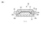
図4乃至図6に示すように、各金型組20は、成形品2の上側の形状に対応して形成される上金型21(上型)と、上金型21に対向して配置されるとともに成形品2の下側の形状に対応して形成される下金型22(下型)と、上金型21及び下金型22の外側を囲み支持するスリーブ23と、下金型22の下側に敷設されたバックプレート24と、を備えている。 As shown in FIGS. 4 to 6, each
上金型21及び下金型22は、閉状態で成形品2の形状に対応したキャビティを有する所定サイズの矩形状を成している。この上金型21と下金型22との間に例えば板状の被成形材1が配置される。上金型21及び下金型22の材料は対耐熱性に優れ、高温化の材料強度がある材料を用いる。例えば、ガラス状カーボン、グラファイト、C/Cコンポジットなどを用いる。 The
上金型21は例えば図5に示すように、上部が下部よりも外方に突出する段差形状となっている。 For example, as shown in FIG. 5, the
下金型22はその外周において外方に突出する鍔状の突出部22aを備えている。例えば図5に示すように、下金型22の下部が上部よりも外方に突出する段差形状となっており、この下部が突出部22aを構成している。 The
上金型21及び下金型22は矩形状のスリーブ23の設置部23aに挿入支持されている。 The
スリーブ23は、グラファイト、C/Cコンポジット、超硬、タングステン合金等の耐熱材料からなり、矩形の枠状に構成されている。スリーブ23の中央部に上金型21及び下金型22が挿入保持される設置部23aが形成されている。スリーブ23は上金型21及び下金型22の外面に沿って対向する段差形状を成し、この段差によって上金型21及び下金型22が所定の位置に位置決めされる。 The
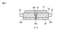
スリーブ23の搬送経路方向の両側の端面には、搬送方向に突出する一対の連結ピン25(連結部)が形成されている。連結ピン25は、例えば、熱伝導率の小さな窒化珪素(Si3N4)、ステンレス鋼等の材質で構成される軸体であって、隣り合うユニットに配置された連結ピン25同士が搬送方向において連続するように突き当たり、後述する搬送ユニット70による押し出し力を伝達する。連結ピン25は例えば搬送方向両側において、それぞれ搬送経路の幅方向両側に2本ずつ、計4本設けられている。 A pair of connecting pins 25 (connecting portions) projecting in the transport direction are formed on both end faces of the
両側の連結ピン25を含むスリーブ23の搬送方向における長さは、搬入ユニット80、加熱ユニット30、プレスユニット40、徐冷ユニット50、急冷ユニット60、搬出ユニット90、のユニット同士の間隔であるユニットピッチP1と同じ長さに設定されている。すなわち、隣り合うユニットに載置される金型組20の連結ピン25同士が互いに当接して連続するように構成されている。 The length in the conveyance direction of the
バックプレート24は一定の厚みを有する矩形の板状に構成され、下金型22の下側に配置されている。バックプレート24は例えばモリブデン、タングステン合金、C/Cコンポジット等の材料からなる。 The
図4及び図6に示すように、バックプレート24は、金型組20の搬送方向と直交する幅方向両端においてスリーブ23に対してボルトB等の固定具で締結されている。このバックプレート24とスリーブ23との固定によって、スリーブ23の段差とバックプレート24との間に形成される空間に突出部22aが挟持され、下金型22が位置決め固定される。 As shown in FIGS. 4 and 6, the
また、バックプレート24の下面における搬送方向両端部には上下方向及び搬送方向に対して傾斜する傾斜面を有する案内部24aが形成されている。案内部24aは例えば10〜20度の傾斜に設定されている。この案内部24aによって、隣り合うユニットのプレートの上面の間において金型組20の押し出し搬送がスムーズに行われる。 Further, guide
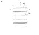
図7に示すように、バックプレート24の下面には、複数(ここでは5本)のエア抜き用の溝24bが形成されている。この溝24bはいずれも搬送方向に沿って平行に延びている。すべり摩擦を軽減させ、バックプレート24をスライドさせる搬送処理が搬送方向に沿ってスムーズに行われる。 As shown in FIG. 7, a plurality of (here, five)
搬送方向に並列配置された複数の加熱ユニット30は、それぞれ、金型組20を挟むように上下に配置された上側ヒータ部31及び下側ヒータ部32を備えている。上側ヒータ部31及び下側ヒータ部32にはヒータ機構としての赤外線ランプ34がそれぞれ複数列配置されて設置されている。 Each of the plurality of
下側の赤外線ランプ34の列上には、金型組20が載置される載置プレート35が固定されている。載置プレート35は例えば熱伝導性の高いSiC等の材料からなり、矩形の板状に構成されている。以上のように構成された加熱ユニット30において、搬送ユニット70により順次送られる金型組20が下側の載置プレート35上に載置された状態で、加熱処理がなされる。 A
搬送方向に並列配置された複数のプレスユニット40は、それぞれ、金型組20を挟むように配置された上下一対のプレスプレート46を備えている。各プレスプレート46は、矩形の板状に構成され、熱伝導性が良くかつ硬質材である超硬あるいはSiCなどの材料で構成される。このプレスプレート46にはヒータ機構としての赤外線ランプ45が設けられている。上側のプレスプレート46にはプレス軸42が接続されている。プレス軸42はサーボモータ、エアシリンダなどの昇降機構部43に接続され、制御部の制御に応じて上下動するように構成されている。 Each of the plurality of
以上のように構成されたプレスユニット40において、一対のプレート46間に設置された金型組20を赤外線ランプ45で加熱処理するとともに、上側のプレスプレート46の昇降動によって上側のプレスプレート46を下降させ、一対のプレスプレート46間の金型組20を加圧するプレス処理がなされる。 In the
搬送方向に並列配置された第2の冷却ユニットとしての徐冷ユニット50は、金型組20を挟むように上下に配置された上下の徐冷プレート51(冷却部)を備えて構成されている。 The
上下の徐冷プレート51は、矩形の板状に構成され、熱伝導性が良くかつ硬質材である超硬あるいはSiC等の材料で構成される。上下の徐冷プレート51には、徐冷用のヒータ機構としての赤外線ランプ56が組み込まれている。上下の徐冷プレート51間には金型組20が通過する通路が形成されている。 The upper and lower
下側の徐冷プレート51は下側のプレスプレート46と同様に構成されている。上側の徐冷プレート51は上側のプレスプレート46と同様に、プレス軸が接続されており、昇降機構部63によって上下に昇降可能な構成となっている。 The
昇降機構部63によって上側の徐冷プレート51を下降させ、下側の徐冷プレート51上に置かれた金型組20を加圧することで一定のプレス力を維持する保圧を行いながら、徐冷処理がなされる。 While the elevating
第2の冷却ユニットとしての急冷ユニット60は、金型組20を挟むように上下に配置された上下の冷却プレート61(冷却部)と、上側の冷却プレート61に連結して上下方向に延びる支持軸62と、上側の冷却プレート61に接続されるサーボモータあるいはエアシリンダなどの昇降機構部63と、を備えて構成されている。 The
上下の冷却プレート61は、矩形の板状に構成され、熱伝導性が良くかつ硬質材である超硬、SiC、焼き入れされたステンレス等の材料で構成される。冷却プレート61には、冷却触媒を流す流路を構成する冷媒配管が組み込まれている。また、上下の冷却プレート61には、複数の熱電対がそれぞれ設けられている。さらに上側の冷却プレート61は昇降機構部63によって上下に昇降可能な構成となっている。 The upper and
昇降機構部63を駆動して上側の冷却プレート61を下降させ、下側の冷却プレート61上に置かれた金型組20に接触及び加圧することにより急冷処理がなされる。 The elevating
なお、各ユニット30,40,50,60には熱電対が設けられ、処理中の温度を検出して制御部12でのフィードバック制御に用いる。 Each
図1乃至図3に示すように、搬入ユニット80は搬送方向における一端側、すなわち加熱ユニット30の隣(図中右側)に配置されている。搬出ユニット90は、搬送方向における他端側、すなわち急冷ユニット60の下流側に配置されている。 As shown in FIGS. 1 to 3, the carry-in
搬送ユニット70は、搬送方向に沿って往復動するシリンダ軸71と、制御部に接続されてシリンダ軸71を搬送方向に移動させる押し出し機構としての搬送用エアシリンダ72と、搬送方向下流側において金型組20の位置を規制するストッパ部73と、を備えている。 The
シリンダ軸71は連結ピン25と同軸に延びている。搬送用エアシリンダ72は、隔離チャンバ11の搬入側の端部に設置され、搬送方向に沿って一定ストロークで、連結ピン25を押し出しする機能を有する。押し出される連結ピン25の移動に伴って、各金型組20が搬送経路に沿って押し出しされることにより、複数の金型組20をまとめて一定ストロークで一端側から他端側へ順番に搬送する。 The
搬入ユニット80は、金型組20を載置し昇降移動する搬入プレート81と、搬入ステーションの上部に設けられたロードロック室82と、搬入プレート81を移動させる昇降機構部83と、ロードロック室82の下部に設けられる移動機構部84と、を備えている。 The carry-in
搬出ユニット90は、搬送方向における他端側、すなわち急冷ユニット60の下流側に配置されている。搬出ユニット90は、金型組20を載置し昇降移動する搬出プレート91と、搬出ステーションの上部に設けられたロードロック室92と、搬出プレート91を移動させる昇降機構部93と、ロードロック室92の下部に設けられる移動機構部94と、を備えている。 The carry-out
さらに、成形装置10の隔離チャンバ11の外には、成形品2を複数保持する成形品ストッカ13、金型組20やダミー金型組20Aを複数保持する金型ストッカ14、被成形材1を保管する素材ストッカ15が設けられている。 Further, outside the
以下、本実施の形態に係る成形装置10を用いて、被成形材1から成形品2を製造する手順について説明する。成形品2の一例としては、例えば4〜12inサイズ、厚さ0.3〜1.5mm程度のスマートフォンのカバーガラスが挙げられるが、これに限られるものではなく、各種の形状・用途に適用できる。例えばプレート状の被成形材1から、両端部が湾曲した形状や端部の厚みが変化するような形状の成形品2を製造することも可能である。 Hereinafter, a procedure for manufacturing the molded
成形装置10においては、各ユニットに1つずつ金型組20が配置され、複数のユニットでの複数の処理を並行して行うが、以下説明のために1つの金型組20を中心として手順を説明する。 In the
すなわち、1つのユニットにおいて1つの金型組20に対する処理が行われ、他の処理ユニットでは、他の金型組20に対しての処理が行われる。図1乃至図3では各ユニットに夫々1つずつ金型組20が配置されている場合を示している。 That is, processing for one mold set 20 is performed in one unit, and processing for another mold set 20 is performed in another processing unit. FIGS. 1 to 3 show a case where one die set 20 is arranged in each unit.
まず、金型ストッカ14の金型組20に、素材ストッカ15の被成形材1をセットする。 First, the
搬入処理として、ロードロック室82内に金型組20をセットし、ロードロック室82内を閉じる。次に昇降機構部83で金型組20を下降させる。下降後、移動機構部84により、金型組20を搬送ユニット70によって押し出しが行われる位置まで水平に移動させる。 As a carry-in process, the mold set 20 is set in the load lock chamber 82 and the load lock chamber 82 is closed. Next, the die set 20 is lowered by the lifting mechanism 83. After the lowering, the moving mechanism unit 84 moves the mold set 20 horizontally to the position where the
ストッカ14からロードロック室82へ金型組20を移動させる際には例えば搬送用のロボットアームで金型組20を把持して移動させる。このとき、スリーブ23及びバックプレート24を把持することにより、上金型21及び下金型22を損傷することなく、移動させることが可能となる。 When the mold set 20 is moved from the
加熱ユニット30など他のユニットの処理が完了した所定のタイミングで、制御部12はシリンダ軸71を駆動し、金型組20の連結ピン25を押圧して、ユニットピッチP1に一定距離を加算したピッチP2の分下流側に移動させ、金型組20を1つ目の加熱ユニット30の載置プレート35上へ移動する(搬送処理)。同時に下流側に並ぶ複数の金型組20も、連結ピン25によって押し出され、ユニットピッチP1ずつ、下流側に移動する。すなわち、複数の金型の連結ピン25が、下流側の金型組20を押圧することになるため、シリンダ軸71が金型組20を一斉に移動させることになる。 At a predetermined timing when the processing of other units such as the
1つ目の加熱ユニット30において、上下の赤外線ランプ34で金型組20を加熱し、所定の温度で被成形材1を軟化させる(加熱処理)。並行する複数の処理が終了したタイミングで、上述と同様の搬送処理によって、順次下流側に送り、同様に加熱処理を施す。 In the
次に、同様の搬送処理によって複数の金型組20を一括で下流側に移動させ、下流側の加熱ユニット30から1つ目のプレスユニット40へ金型組20を搬送する。 Next, the plurality of mold sets 20 are collectively moved downstream by the same transfer process, and the mold sets 20 are transferred from the
制御部12はプレスユニット40の昇降機構部43を駆動して上側のプレスプレート46を下降させ、金型組20を上下のプレスプレート46で挟み込むことにより、被成形材1を加熱しながらプレス成形する(プレス処理)。並行する複数の処理が終了したタイミングで、上述と同様の搬送処理によって、順次下流側に送り、下流側のプレスユニット40において同様にプレス処理をする。 The
続いて、同様の搬送処理によって、下流側のプレスユニット40から1つ目の徐冷ユニット50へ金型組20を搬送する。徐冷ユニット50では、一対の徐冷プレート51によって保圧しながら、例えばヒータの温度調節により金型組20を所定の温度になるように処理する(徐冷処理)。 Subsequently, the mold set 20 is transported from the
ついで、上述と同様の搬送処理によって、金型組20を、徐冷ユニット50から急冷ユニット60へ搬送する。制御部12は急冷ユニット60の昇降機構部63を駆動して上側の冷却プレート61を下降させ、金型組20を上下の冷却プレート61で挟み込むことにより、冷媒により、大気中においても酸化されない温度域まで冷却する(急冷処理)。 Next, the mold set 20 is transported from the
続いて、搬出処理を行う。搬出処理としては、まず搬送路脇に設けられた移動機構部76によって金型組20をユニットピッチP1に一定距離を加算したピッチP3の分だけ下流側に移動させた後、移動機構部94によりロードロック室92の真下の位置まで水平移動させる。その後、昇降機構部93により金型組20を上に移動する。ロードロック室92まで移動したら、ロードロック室92を開放し、金型組20を取り出す。 Subsequently, an unloading process is performed. As the carry-out process, first, the mold set 20 is moved to the downstream side by a pitch P3 obtained by adding a certain distance to the unit pitch P1 by the moving
搬出された金型組20は隔離チャンバ11外で分解され、取り出された成形品2は成形品ストッカ13にセットされる。使用後の金型組20に新たな被成形材1をセットし、再び上述の成形処理が行われる。 The unloaded mold set 20 is disassembled outside the
搬出位置からストッカ14へ金型組20を移動させる際には例えば搬送用のロボットアームで金型組20を把持して移動させる。このとき、スリーブ23及びバックプレート24を把持することにより、上金型21及び下金型22を損傷することなく、移動させることが可能となる。 When the mold set 20 is moved from the carry-out position to the
本実施形態によれば、下金型22の下側にバックプレート24を設けたことにより、上金型21及び下金型22の厚さを小さく抑えつつ金型組20の高さを確保し、搬送性を向上することができる。一般的に、ガラス状カーボンの材質組織が均質でない場合に衝撃を受けて組織内部に応力の偏りが生じるため、金型の材料としてガラス状カーボンを用いる場合には厚さが厚くなるほど内部組織の差が生じやすく破損やチッピング等の損傷現象が発生しやすい。このため、材料によっては破損を防止するために金型の厚さが制限され、金型全高が低くなるので搬送しにくいが、本実施形態では下金型22の裏面にバックプレート24を設けることで、下金型22の材料に関わらず損傷を回避しつつ、金型組20の高さを確保し、搬送性を向上できる。 According to this embodiment, by providing the
本実施形態では、バックプレート24が並列するプレート上を滑り移動することにより、下金型22の損傷を防止できる。また、金型組20において搬送方向に突出する連結ピン25を設けてこれを連続させることで、複数の金型組20を一括で搬送することにより、処理効率を向上できる。 In the present embodiment, the
また、本実施形態によれば、スリーブ23とバックプレート24とが下金型22の突出部を挟んでボルトBで固定される構成としたことにより。下金型22にねじ孔等の固定用構造を形成せずに固定することができる。 In addition, according to the present embodiment, the
さらに、上記実施形態ではバックプレート24の下面に案内部24aを設けたことで、並列するプレート間の段差に妨げられることなく進行方向にスムーズなスライド移動が可能となる。また、バックプレート24の下面にエア抜き用の溝24bを設けたことにより、加熱処理や加圧処理によってバックプレート24が吸着することがなく、進行方向へのスムーズなスライド移動が可能となり、搬送性を向上できる。 Further, in the above embodiment, the
本実施形態では金型組20の金型本体は上金型21、下金型22の2ピース構成であるが、上金型、中金型、下金型の3ピース構成にしてもよい。 In the present embodiment, the mold body of the mold set 20 has a two-piece configuration of an
なお、本発明は上記各実施形態に限定されるものではなく、適宜変更して実施可能である。また複数の実施形態の特徴を組み合わせて実施することも可能である。この他、本発明の要旨を逸脱しない範囲で種々変形実施可能であるのは勿論である。
以下に、本願出願の当初の特許請求範囲に記載された発明を付記する。
[1]
複数のパーツを備え、被成形材を保持する型と、
前記型の下側に敷設されたバックプレートと、を備えたことを特徴とする金型組。
[2]
前記型の外周を囲むスリーブを備え、
前記型は、外方に突出する突出部を備え、
前記スリーブと前記バックプレートとが、間に前記突出部を挟持して互いに組み付けられることを特徴とする[1]記載の金型組。
[3]
前記スリーブは搬送方向に沿って延びる連結部を備え、
前記連結部を押し出す押し出し処理に伴い搬送方向にスライド移動することを特徴とする[2]記載の金型組。
[4]
前記金型組の進行方向端部には下面が傾斜した案内部を備えることを特徴とする[1]乃至[3]のいずれか記載の金型組。
[5]
前記バックプレートの下面に、進行方向に沿う溝が形成されていることを特徴とする[1]乃至[4]のいずれか記載の金型組。
[6]
前記バックプレートは前記型とは異なる材質で構成されたことを特徴とする[1]乃至[5]のいずれか記載の金型組。
[7]
前記金型組を加熱する加熱ユニットに設けられたプレート上、前記金型組を加圧するプレスユニットに設けられたプレート上、及び前記金型組を冷却する冷却ユニットに設けられたプレート上、を通る所定の搬送路において前記プレート上をスライド移動して搬送されることを特徴とする[1]乃至[5]のいずれか記載の金型組。
In addition, this invention is not limited to said each embodiment, It can implement by changing suitably. It is also possible to combine the features of a plurality of embodiments. Of course, various modifications can be made without departing from the scope of the present invention.
The invention described in the initial claims of the present application will be appended below.
[1]
A mold comprising a plurality of parts and holding a material to be molded,
A mold set comprising a back plate laid on the lower side of the mold.
[2]
Comprising a sleeve surrounding the outer periphery of the mold,
The mold includes a protruding portion that protrudes outward,
The mold set according to [1], wherein the sleeve and the back plate are assembled to each other with the projecting portion interposed therebetween.
[3]
The sleeve includes a connecting portion extending along a conveying direction;
The mold set according to [2], wherein the mold assembly slides in a transport direction in accordance with an extrusion process for extruding the connecting portion.
[4]
The mold set according to any one of [1] to [3], wherein a guide part having an inclined lower surface is provided at an end portion in the traveling direction of the mold set.
[5]
The die set according to any one of [1] to [4], wherein a groove along the traveling direction is formed on the lower surface of the back plate.
[6]
The mold set according to any one of [1] to [5], wherein the back plate is made of a material different from that of the mold.
[7]
On a plate provided in a heating unit for heating the mold set, on a plate provided in a press unit for pressurizing the mold set, and on a plate provided in a cooling unit for cooling the mold set. The mold set according to any one of [1] to [5], wherein the mold set is transported by sliding on the plate in a predetermined transport path.
B…ボルト、1…被成形材、2…成形品、20…金型組、21…上金型(上型)、22…下金型(下型)、22a…突出部、23…スリーブ、23a…設置部、24…バックプレート、24a…案内部、24b…溝、25…連結ピン、30…加熱ユニット、35…載置プレート、40…プレスユニット、46…プレスプレート、50…徐冷ユニット、51…徐冷プレート、60…急冷ユニット、61…冷却プレート、70…搬送ユニット。 B ... Bolt, 1 ... Material to be molded, 2 ... Molded product, 20 ... Mold set, 21 ... Upper die (upper die), 22 ... Lower die (lower die), 22a ... Projection, 23 ... Sleeve, 23a ... installation part, 24 ... back plate, 24a ... guide part, 24b ... groove, 25 ... connecting pin, 30 ... heating unit, 35 ... mounting plate, 40 ... press unit, 46 ... press plate, 50 ...
Claims (6)
Translated fromJapanese前記型の下側に敷設されたバックプレートと、を備え、
前記バックプレートの下面に、進行方向に沿う溝が形成されていることを特徴とする金型組。A mold comprising a plurality of parts and holding a material to be molded,
A back plate laid on the lower side of the mold,
A mold set,wherein a groove along the traveling direction is formed on the lower surface of the back plate .
前記型は、外方に突出する突出部を備え、
前記スリーブと前記バックプレートとが、間に前記突出部を挟持して互いに組み付けられることを特徴とする請求項1記載の金型組。Comprising a sleeve surrounding the outer periphery of the mold,
The mold includes a protruding portion that protrudes outward,
The mold set according to claim 1, wherein the sleeve and the back plate are assembled to each other with the protruding portion interposed therebetween.
前記連結部を押し出す押し出し処理に伴い搬送方向にスライド移動することを特徴とする請求項2記載の金型組。The sleeve includes a connecting portion extending along a conveying direction;
The mold set according to claim 2, wherein the mold assembly slides in a conveying direction in accordance with an extrusion process for extruding the connecting portion.
Priority Applications (5)
| Application Number | Priority Date | Filing Date | Title |
|---|---|---|---|
| JP2013108158AJP6116366B2 (en) | 2013-05-22 | 2013-05-22 | Mold assembly |
| TW103117147ATWI580549B (en) | 2013-05-22 | 2014-05-15 | Mold group |
| US14/283,958US9505149B2 (en) | 2013-05-22 | 2014-05-21 | Mold set |
| CN201410217936.XACN104176916B (en) | 2013-05-22 | 2014-05-21 | Mold set |
| KR1020140060996AKR101603415B1 (en) | 2013-05-22 | 2014-05-21 | Mold set |
Applications Claiming Priority (1)
| Application Number | Priority Date | Filing Date | Title |
|---|---|---|---|
| JP2013108158AJP6116366B2 (en) | 2013-05-22 | 2013-05-22 | Mold assembly |
Publications (2)
| Publication Number | Publication Date |
|---|---|
| JP2014227317A JP2014227317A (en) | 2014-12-08 |
| JP6116366B2true JP6116366B2 (en) | 2017-04-19 |
Family
ID=51935542
Family Applications (1)
| Application Number | Title | Priority Date | Filing Date |
|---|---|---|---|
| JP2013108158AActiveJP6116366B2 (en) | 2013-05-22 | 2013-05-22 | Mold assembly |
Country Status (5)
| Country | Link |
|---|---|
| US (1) | US9505149B2 (en) |
| JP (1) | JP6116366B2 (en) |
| KR (1) | KR101603415B1 (en) |
| CN (1) | CN104176916B (en) |
| TW (1) | TWI580549B (en) |
Families Citing this family (6)
| Publication number | Priority date | Publication date | Assignee | Title |
|---|---|---|---|---|
| CN104684855B (en)* | 2012-09-28 | 2018-03-30 | 东芝机械株式会社 | Shaped device and forming method |
| KR102309386B1 (en)* | 2015-01-20 | 2021-10-06 | 삼성디스플레이 주식회사 | Apparatus for processing glass window of display |
| KR101578331B1 (en)* | 2015-10-05 | 2015-12-16 | (주)육일씨엔에쓰 | Device for forming touch window glass for portanle terminal |
| CN206520155U (en)* | 2017-01-25 | 2017-09-26 | 得意精密电子(苏州)有限公司 | The gentle hydraulic support mechanism of injection molding machine |
| CN107382037B (en)* | 2017-08-15 | 2020-09-11 | 深圳市康成泰实业有限公司 | Processing method of 3D (three-dimensional) dot-free glass film |
| CN107686229A (en)* | 2017-09-11 | 2018-02-13 | 成都随如科技有限公司 | The compression molding forming machine of non-spherical lens easy to use |
Family Cites Families (22)
| Publication number | Priority date | Publication date | Assignee | Title |
|---|---|---|---|---|
| US3373460A (en)* | 1965-09-13 | 1968-03-19 | Michael Ladney Jr. | Molding apparatus |
| NL6804865A (en)* | 1967-04-10 | 1968-10-11 | ||
| JP2504817B2 (en)* | 1988-11-16 | 1996-06-05 | キヤノン株式会社 | Optical element molding method |
| US5173100A (en)* | 1988-11-16 | 1992-12-22 | Canon Kabushiki Kaisha | Molding method for optical element |
| JPH02192423A (en)* | 1989-01-19 | 1990-07-30 | Canon Inc | Formation of optical element |
| JPH0688614B2 (en)* | 1992-07-13 | 1994-11-09 | 静男 佐藤 | Paper protector having multiple structure and manufacturing apparatus thereof |
| FR2715335B1 (en)* | 1994-01-21 | 1996-04-05 | Lorraine Laminage | Device for stamping a sheet blank. |
| JPH09239757A (en) | 1996-03-13 | 1997-09-16 | Matsushita Electric Ind Co Ltd | Optical device molding apparatus and molding method |
| JPH09268019A (en) | 1996-04-03 | 1997-10-14 | Olympus Optical Co Ltd | Conveyance member for optical material |
| US7699595B2 (en)* | 2004-07-19 | 2010-04-20 | R + S Technik Gmbh | Method and apparatus for molding a laminated trim component without use of slip frame |
| CN1951843B (en)* | 2005-10-21 | 2011-09-28 | 鸿富锦精密工业(深圳)有限公司 | Optic element forming device |
| JP4825494B2 (en) | 2005-11-10 | 2011-11-30 | 東芝機械株式会社 | Glass forming equipment |
| JP2007153647A (en)* | 2005-12-02 | 2007-06-21 | Asahi Glass Co Ltd | Optical element molding apparatus and molding method |
| WO2007083719A1 (en) | 2006-01-19 | 2007-07-26 | Asahi Glass Co., Ltd. | Press-molding apparatus |
| JP2010089970A (en) | 2008-10-03 | 2010-04-22 | Olympus Corp | Molding method, molding apparatus and control program |
| JP5690475B2 (en) | 2009-03-25 | 2015-03-25 | 東芝機械株式会社 | Molding apparatus and method for manufacturing molded product |
| JP5439052B2 (en)* | 2009-06-23 | 2014-03-12 | 東芝機械株式会社 | Molding equipment |
| JP2012116705A (en)* | 2010-11-30 | 2012-06-21 | Asahi Glass Co Ltd | Molding apparatus and molding method for optical device |
| JP2012116697A (en)* | 2010-11-30 | 2012-06-21 | Asahi Glass Co Ltd | Molding die for optical element and method of molding optical element |
| JP5695518B2 (en)* | 2011-07-28 | 2015-04-08 | オリンパス株式会社 | Optical element manufacturing method, optical element molding die set, and optical element manufacturing apparatus |
| CN104684855B (en) | 2012-09-28 | 2018-03-30 | 东芝机械株式会社 | Shaped device and forming method |
| JP5774658B2 (en) | 2013-10-07 | 2015-09-09 | 東芝機械株式会社 | Molding equipment |
- 2013
- 2013-05-22JPJP2013108158Apatent/JP6116366B2/enactiveActive
- 2014
- 2014-05-15TWTW103117147Apatent/TWI580549B/enactive
- 2014-05-21USUS14/283,958patent/US9505149B2/enactiveActive
- 2014-05-21CNCN201410217936.XApatent/CN104176916B/enactiveActive
- 2014-05-21KRKR1020140060996Apatent/KR101603415B1/enactiveActive
Also Published As
| Publication number | Publication date |
|---|---|
| CN104176916A (en) | 2014-12-03 |
| JP2014227317A (en) | 2014-12-08 |
| KR101603415B1 (en) | 2016-03-14 |
| US20140348970A1 (en) | 2014-11-27 |
| TWI580549B (en) | 2017-05-01 |
| US9505149B2 (en) | 2016-11-29 |
| TW201518057A (en) | 2015-05-16 |
| KR20140137315A (en) | 2014-12-02 |
| CN104176916B (en) | 2017-04-12 |
Similar Documents
| Publication | Publication Date | Title |
|---|---|---|
| JP5934801B2 (en) | Molding equipment | |
| JP6116366B2 (en) | Mold assembly | |
| JP2006289425A (en) | Hot press molding method and apparatus | |
| WO2015037488A1 (en) | Glass-moulded-body production apparatus | |
| JP5774658B2 (en) | Molding equipment | |
| JP5814669B2 (en) | Conveyor for hot press | |
| KR101778232B1 (en) | Forming apparatus | |
| JP5439052B2 (en) | Molding equipment | |
| TWI601703B (en) | Glass forming furnace | |
| JP6051272B2 (en) | Molding equipment | |
| WO2013047306A1 (en) | Press-molding device, press-molding method, mounting plate for press-molding | |
| CN106103365B (en) | Manufacturing equipment for optical components | |
| JP2007131466A (en) | Optical lens manufacturing method and optical lens manufacturing apparatus | |
| JP6057421B2 (en) | Hot press forming equipment | |
| JP4759362B2 (en) | Optical element manufacturing apparatus and manufacturing method | |
| JP2013112592A (en) | Apparatus and method for molding optical element | |
| JP6306988B2 (en) | Conveying unit and molding apparatus | |
| JPH05306128A (en) | Method and apparatus for molding optical element | |
| JP2019011224A (en) | Glass molding device | |
| JPH06211530A (en) | Method for forming optical element and device therefor |
Legal Events
| Date | Code | Title | Description |
|---|---|---|---|
| A621 | Written request for application examination | Free format text:JAPANESE INTERMEDIATE CODE: A621 Effective date:20160205 | |
| A977 | Report on retrieval | Free format text:JAPANESE INTERMEDIATE CODE: A971007 Effective date:20160812 | |
| A131 | Notification of reasons for refusal | Free format text:JAPANESE INTERMEDIATE CODE: A131 Effective date:20160823 | |
| A521 | Written amendment | Free format text:JAPANESE INTERMEDIATE CODE: A523 Effective date:20161021 | |
| TRDD | Decision of grant or rejection written | ||
| A01 | Written decision to grant a patent or to grant a registration (utility model) | Free format text:JAPANESE INTERMEDIATE CODE: A01 Effective date:20170221 | |
| A61 | First payment of annual fees (during grant procedure) | Free format text:JAPANESE INTERMEDIATE CODE: A61 Effective date:20170321 | |
| R150 | Certificate of patent or registration of utility model | Ref document number:6116366 Country of ref document:JP Free format text:JAPANESE INTERMEDIATE CODE: R150 | |
| S533 | Written request for registration of change of name | Free format text:JAPANESE INTERMEDIATE CODE: R313533 | |
| R350 | Written notification of registration of transfer | Free format text:JAPANESE INTERMEDIATE CODE: R350 |