JP6112640B2 - Cooling assembly - Google Patents
Cooling assemblyDownload PDFInfo
- Publication number
- JP6112640B2 JP6112640B2JP2015534447AJP2015534447AJP6112640B2JP 6112640 B2JP6112640 B2JP 6112640B2JP 2015534447 AJP2015534447 AJP 2015534447AJP 2015534447 AJP2015534447 AJP 2015534447AJP 6112640 B2JP6112640 B2JP 6112640B2
- Authority
- JP
- Japan
- Prior art keywords
- fluid
- heat
- thermal
- cooling
- support member
- Prior art date
- Legal status (The legal status is an assumption and is not a legal conclusion. Google has not performed a legal analysis and makes no representation as to the accuracy of the status listed.)
- Expired - Fee Related
Links
Images


Classifications
- F—MECHANICAL ENGINEERING; LIGHTING; HEATING; WEAPONS; BLASTING
- F28—HEAT EXCHANGE IN GENERAL
- F28F—DETAILS OF HEAT-EXCHANGE AND HEAT-TRANSFER APPARATUS, OF GENERAL APPLICATION
- F28F13/00—Arrangements for modifying heat-transfer, e.g. increasing, decreasing
- F28F13/06—Arrangements for modifying heat-transfer, e.g. increasing, decreasing by affecting the pattern of flow of the heat-exchange media
- H—ELECTRICITY
- H01—ELECTRIC ELEMENTS
- H01L—SEMICONDUCTOR DEVICES NOT COVERED BY CLASS H10
- H01L23/00—Details of semiconductor or other solid state devices
- H01L23/34—Arrangements for cooling, heating, ventilating or temperature compensation ; Temperature sensing arrangements
- H01L23/46—Arrangements for cooling, heating, ventilating or temperature compensation ; Temperature sensing arrangements involving the transfer of heat by flowing fluids
- H01L23/473—Arrangements for cooling, heating, ventilating or temperature compensation ; Temperature sensing arrangements involving the transfer of heat by flowing fluids by flowing liquids
- H—ELECTRICITY
- H05—ELECTRIC TECHNIQUES NOT OTHERWISE PROVIDED FOR
- H05K—PRINTED CIRCUITS; CASINGS OR CONSTRUCTIONAL DETAILS OF ELECTRIC APPARATUS; MANUFACTURE OF ASSEMBLAGES OF ELECTRICAL COMPONENTS
- H05K7/00—Constructional details common to different types of electric apparatus
- H05K7/20—Modifications to facilitate cooling, ventilating, or heating
- H05K7/20709—Modifications to facilitate cooling, ventilating, or heating for server racks or cabinets; for data centers, e.g. 19-inch computer racks
- H05K7/20763—Liquid cooling without phase change
- H05K7/20781—Liquid cooling without phase change within cabinets for removing heat from server blades
- H—ELECTRICITY
- H05—ELECTRIC TECHNIQUES NOT OTHERWISE PROVIDED FOR
- H05K—PRINTED CIRCUITS; CASINGS OR CONSTRUCTIONAL DETAILS OF ELECTRIC APPARATUS; MANUFACTURE OF ASSEMBLAGES OF ELECTRICAL COMPONENTS
- H05K7/00—Constructional details common to different types of electric apparatus
- H05K7/20—Modifications to facilitate cooling, ventilating, or heating
- H05K7/20709—Modifications to facilitate cooling, ventilating, or heating for server racks or cabinets; for data centers, e.g. 19-inch computer racks
- H05K7/208—Liquid cooling with phase change
- H05K7/20809—Liquid cooling with phase change within server blades for removing heat from heat source
- H—ELECTRICITY
- H01—ELECTRIC ELEMENTS
- H01L—SEMICONDUCTOR DEVICES NOT COVERED BY CLASS H10
- H01L2924/00—Indexing scheme for arrangements or methods for connecting or disconnecting semiconductor or solid-state bodies as covered by H01L24/00
- H01L2924/0001—Technical content checked by a classifier
- H01L2924/0002—Not covered by any one of groups H01L24/00, H01L24/00 and H01L2224/00
Landscapes
- Engineering & Computer Science (AREA)
- Physics & Mathematics (AREA)
- Computer Hardware Design (AREA)
- Microelectronics & Electronic Packaging (AREA)
- General Engineering & Computer Science (AREA)
- Thermal Sciences (AREA)
- Condensed Matter Physics & Semiconductors (AREA)
- General Physics & Mathematics (AREA)
- Power Engineering (AREA)
- Mechanical Engineering (AREA)
- Cooling Or The Like Of Electrical Apparatus (AREA)
Description
Translated fromJapanese電子装置には、温度に関する必要条件が存在する。電子装置の使用に起因する熱は、冷却システムを用いて制御される。冷却システムの例としては、空気冷却式のもの、液体冷却式のもの等が挙げられる。 There are temperature requirements for electronic devices. The heat resulting from the use of the electronic device is controlled using a cooling system. Examples of the cooling system include an air cooling type and a liquid cooling type.
本開示における非限定的な実施形態は、以下の説明のように記載されていて、添付図面を参照しながら読み取ることができるが、これらは特許請求の範囲を限定するものではない。図面において2つ以上の図面に現わした同一及び類似の構造、要素、又は部品については、典型的には、それぞれを現わした図面において同じ又は類似の符号を付している。図面に示す構成要素及び特徴の寸法は、主として表示の便宜を図るため及び明確化を図るために定められていて、必ずしも正確な縮尺とはなっていない。ここで、添付図面について次に述べる。 Non-limiting embodiments in the present disclosure are described as follows and can be read with reference to the accompanying drawings, which do not limit the scope of the claims. In the drawings, identical and similar structures, elements or parts appearing in more than one drawing are typically labeled with the same or similar reference numerals in the respective drawings. The dimensions of the components and features shown in the drawings are determined mainly for the convenience of display and for clarity, and are not necessarily to scale. The attached drawings will now be described.
以下の詳細な説明においては、本明細書の一部を構成すると共に、本開示を実施可能な特定の実施形態を一例として示した添付図面を参照されたい。しかしながら、他の実施形態を利用してもよく、本開示の範囲から逸脱することなく構造的又は論理的な変更を行ってもよいものと理解すべきである。 In the following detailed description, reference is made to the accompanying drawings that form a part hereof, and in which is shown by way of illustration specific embodiments in which the disclosure may be practiced. However, it should be understood that other embodiments may be utilized and structural or logical changes may be made without departing from the scope of the present disclosure.
電子システムの設計においては、電力密度、空間レイアウト、温度条件、音響ノイズ等の要素間の対立を調整する必要がある。空気冷却システムは、通常、ヒートシンク及びファンを用いて「廃棄」熱をシステムから除去するようになっている。ヒートシンク及びファンを用いると、電子システムの電子装置を動作させるために必要な電力が増大することと共に、音響ノイズが大きくなり過ぎること、及びシステム密度が低くなることが起こる場合がある。液体冷却は、空気冷却よりも高効率となる可能性がある。しかしながら、液体冷却では、通常、電子装置に配管接続体が含まれる。液体が配管接続体を流れると、電子装置における液体漏れの危険性が生じる。 In the design of electronic systems, it is necessary to adjust the conflict between factors such as power density, spatial layout, temperature conditions, and acoustic noise. Air cooling systems typically use heat sinks and fans to remove “waste” heat from the system. With heat sinks and fans, the power required to operate the electronic devices of the electronic system may increase, acoustic noise may become excessive, and system density may decrease. Liquid cooling can be more efficient than air cooling. However, in liquid cooling, a pipe connector is usually included in an electronic device. When the liquid flows through the pipe connection body, there is a risk of liquid leakage in the electronic device.
本実施形態においては、冷却システムと併用可能な組立体が提供される。この組立体は、電子装置に接続されるようになっている。電子装置からの熱は、ドライディスコネクト(dry disconnect)を介して組立体に伝達される。この組立体は、支持部材、流路、及び流体制御機構を備えている。支持部材は、熱部材を支持するように構成されている。また、支持部材は、熱部材を受け入れるように形成された受入要素を有する。流路は、支持部材に形成され、かつ流体を運ぶように構成されている。流体制御機構は、流路に沿って、流体の流れを制御するように構成されている。電子装置から熱部材に熱が伝達され、熱部材と接触した流体が熱部材から熱を除去し、その流体が流路を介して組立体から除去されることとなる。この組立体は、電子装置の外部に配置されて、電子装置から離れて液体冷却を行うことができるので、電子装置における流体漏れの危険性を低減することができる。 In this embodiment, an assembly that can be used with a cooling system is provided. This assembly is adapted to be connected to an electronic device. Heat from the electronic device is transferred to the assembly via a dry disconnect. The assembly includes a support member, a flow path, and a fluid control mechanism. The support member is configured to support the thermal member. The support member also includes a receiving element configured to receive the thermal member. The flow path is formed in the support member and configured to carry fluid. The fluid control mechanism is configured to control the flow of fluid along the flow path. Heat is transferred from the electronic device to the heat member, and the fluid in contact with the heat member removes heat from the heat member, and the fluid is removed from the assembly through the flow path. Since this assembly can be disposed outside the electronic device and perform liquid cooling away from the electronic device, the risk of fluid leakage in the electronic device can be reduced.
図1は、一実施形態において、冷却システムと併用可能な組立体100のブロック図である。組立体100は、支持部材120、受入要素130、流路140、及び流体制御機構160を備えている。支持部材120は、電子装置に近接又は隣接して配置された構造部材となっている。支持部材120は、熱部材を支持するように構成されている。また、支持部材120は受入要素130を有している。受入要素130は、熱部材を受け入れるように形成されている。熱部材は、別の熱伝導材料と接触して設けられた場合にそこからの熱を受ける熱伝導材料を含むように形成された構造体となっている。例えば、熱部材は、電子装置からの熱を受けるようになっている。 FIG. 1 is a block diagram of an
流路140は、支持部材120内に形成され、かつ流体を運ぶように構成されており、かかる流路140は、流体を受け入れ、熱部材全体に流体を提供及び/又は分配し、さらに、熱部材及び/又は支持部材120から流体を除去するように構成されている。また、流路140は、支持部材120の構成に応じて、1つ又は複数の閉鎖流路部又は閉鎖部を有していてもよい。流体制御機構160は、流路140に沿って形成されるか、又は流路140内に形成されていて、流体の流れを制御するようになっている。例えば、流体制御機構160は、熱部材間において流体を均等に分配するようになっている。 The
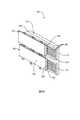
図2〜図4Cは、本実施形態に係る図1の組立体100をさらに示した図である。図2は、一実施形態に係る組立体100の分解図である。かかる組立体100は、支持部材120、受入要素130、流路140、及び流体制御機構160を備えている。 2 to 4C are views further illustrating the
図2を参照すると、支持部材120が、基部222、及び該基部222に接続可能なカバー部224を有している。基部222及びカバー部224は、例えば、当該基部222及びカバー部224を併せて保持するように構成されるクリップ、接着性ガスケット、及び/又はネジ等の締結具220を用いて、相互に接続されていてもよい。図中には、支持部材120の縁部及び/又は内側部に沿って位置する複数の締結具220が示されている。締結具220の配置は、支持部材120、基部222、及びカバー部224の構成に応じて変更されてもよい。また、ガスケット等の密封用部材226を用いると、流体密封が得られることとなる。 Referring to FIG. 2, the
組立体100は、熱部材230をさらに備えている。支持部材120は、熱部材230を受け入れるように形成された受入要素130を介して、熱部材230を受け入れるように構成されている。図2においては、熱部材230の下側に受入要素130が示されており、受入要素130は、熱部材230を受け入れるか又は熱部材230と噛み合うように構成されている。熱部材230は、例えば、当該熱部材230及び受入要素130の少なくとも一方並びに/又はネジ等の締結具220の表面に分配した接着剤によって、所定の位置に保持されている。 The
図2は、流体密封をもたらす基部222及びカバー部224間における密封用部材226を示している。密封用部材226は、ガスケット等の別のシールであってもよいし、支持部材120の構造に組み込まれてもよい。図4Aには、流体密封をもたらす基部222及び熱部材230間における密封用部材226の別の例が示されている。 FIG. 2 shows a sealing
熱部材230においては、一方側に冷却ピン配列要素232が設けられ、反対側に噛合要素234が設けられている。冷却ピン配列要素232は、熱部材230から熱を除去するようになっている。また、冷却ピン配列要素232は、行列状に配列された複数の中実突起を有してもよい。中実突起は、熱部材230の平面部から受入要素130側に延びている。噛合要素234は、電子装置からの熱を受けるようになっている。支持部材120においては、すべての熱部材230が導入又は接続され、かつ密封用部材226が基部222及びカバー部224間並びに基部222及び熱部材230間に設けられた場合に、流体密封用筐体が形成される。 In the
流路140は、支持部材120内において、基部222及びカバー部224間に形成され、かつ流体を運ぶようになっている。流体は、所定の温度にて組立体100に流入し、熱部材230からの熱を吸収して、その温度が上昇する。流体は、通常、高温で組立体100から流出することとなる。 The
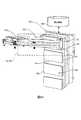
図3は、一実施形態に係る組立体100における流体310の流れの模式図である。流路140は、流体310を受け入れると共に熱部材230に提供して、熱部材230から流体310を除去するようになっている。組立体100においては、この流体の交換が唯一必要とされる。組立体100は、電子装置の外表面に運ばれた熱を除去することによって、電子装置における漏洩の危険性なく電子装置を冷却する効率的な液体冷却方法を提供する。例えば、サーバにおいては、中央処理演算ユニット等の電子的構成要素を設けたサーバ単位ではなくラック単位で液体冷却が行われるようになっている。 FIG. 3 is a schematic diagram of the flow of the fluid 310 in the
図2〜図3を参照すると、図示の流路140は、流入路部242、冷却路部244、及び流出路部246を有している。流入路部242は、流体310を受け入れて熱部材230A〜230E等の熱部材230全体に分配するようになっている。流出路部246は、熱部材230から受け入れた流体310を除去するようになっている。流出路部246及び流入路部242は、熱部材230に接続可能となっている。 Referring to FIGS. 2 to 3, the illustrated
熱部材230は、冷却路部244が熱部材230及び受入要素130間に形成されるように、流入路部242及び流出路部246に直接接続されていてもよい。例えば、冷却路部244は、流体310が冷却ピン配列要素232全体を流れるように、基部222及び熱部材230間に形成される流路又は空洞であって、流体310が流れる、流路又は空洞であってもよい。図2〜図3に示すように、流入路部242は、当該流入路部242に接続された流入部材352を介して流体310を受け入れ、さらに、流出路部246に接続された流出部材354を介して組立体100から流体310を除去するように構成されてもよい。あるいは、熱部材230は、流入路部242及び流出路部246から延びて熱部材230に繋がる補助流路に接続されていてもよい。補助流路は、流体310が冷却ピン配列要素232全体を流れるように、流体310を熱部材230に提供及び/又は分配すると共に、熱部材230から流体310を受け入れるようになっている。 The
流体制御機構160は、流入路部242に沿って形成されるか、又は流入路部242に形成されて、熱部材230に対して流体310を均等に分配するように構成されている。また、流体制御機構160は、熱部材230全体及び流出路部246に沿った流体310の流れ等、流入路部242及び/又は流出路部246内の様々な位置における流体310の流れを制御するように構成されている。図3を参照すると、流体制御機構160においては、例えば、熱部材230A〜230Eのそれぞれに対して流体310が均等に分配されるように、流体310の流れに抗する突起が流入路部242中に設けられている。言い換えると、最初の熱部材230A及び最後の熱部材230Eに対して、略同じ速度及び圧力の流体310が分配される。同様に、流体制御機構160は、流出路部246中の流体310の流れを制御することによって、支持部材120中の流体の圧力を安定させることができる。 The
例えば、図3の流体制御機構160には、流入路部242に沿って流入部材352に近接する突起配列要素262が設けられ、流入路部242に沿って第1組の複数の細長突起264が設けられ、流出路部246に沿って第2組の複数の細長突起266が設けられている。流入路部242全体に延びる突起配列要素262は、最初に、流入路部242に流入する流体310の流れの速度を低減するか、又は流体310の流れに抗するようになっている。第1組の複数の細長突起264は、熱部材230のそれぞれの前段に配置され、かつ流体310の流れに抗する半円筒状の突起として図示されている。第1組の複数の細長突起264によって、僅かな流れ抵抗が流入路部242に生じることとなる。例えば、第1組の複数の細長突起264は、流入開口282を介して、熱部材230に対して流体310を均等に分配すると共に、熱部材230のそれぞれに対して、略同じ速度及び圧力の流体310を提供する。 For example, the
第2組の複数の細長突起266は、流体が組立体100の外部に移動すると、熱部材230及び流出路部246間で流体310の流れに抗するようになっている。第2組の複数の細長突起266は、熱部材230のそれぞれの後段に配置され、かつ流出路部246に沿って移動する流体310の流れを制御する半円筒状の突起として図示されている。第2組の複数の細長突起266によって、僅かな流れ抵抗が流出路部246に生じることとなる。図3に示すように、第1及び第2組の複数の細長突起264、266については、細長突起264、266の数が同じであり、それらがそれぞれ流入路部242及び流出路部246に配置されている。このような対称性によって、流体310の流れが両方向で同様に制御可能となる。 The plurality of
組立体100は、図3に示す受入要素130のそれぞれにて、熱部材230をさらに備えている。受入要素130は、流入路部242及び流出路部246間で延びるように図示されている。冷却路部244は、流体310が熱部材230全体を流れるように、受入要素130及び熱部材間に形成されている。冷却路部244によって、流体310は、流入路部242から熱部材230を通って流出路部246に流れることとなる。 The
受入要素130及び流入路部242間においては、流入開口282が、形成されて、熱部材230に流体310を提供及び/又は分配するようになっている。流体310は、流出開口284(2つの流出開口284,286として図示)を介して熱部材230から流出する。流出開口284,286は、受入要素130及び流出路部246間に形成され、冷却路部244は、流入路部242及び流出路部246間に配置されている。 An
流体制御機構160は、受入要素130及び熱部材230間に形成された冷却路部244に対して流入及び流出する流体310の流れを制御するように構成されている。例えば、流体の制御が行われない場合、すなわち、流体制御機構160が設けられていない場合、流入路部242に流入する流体310は、流入開口282を通過し、最初の熱部材230、すなわち、図3の230Aに向かって流れることがある。流体310は、少なくとも1つの熱部材230を通過して流れると、不均等に分配されて、冷却もまた不均等となる。同様に、流出路部246に示す流体制御機構160は、流体310が組立体100から流出すると、流出開口284,286及び流出部材354間において、流体310の流れを制御するか、又は速度を低減することとなる。 The
図3は、一実施形態に係る組立体100における流体310の流れの模式図である。流体310は、組立体100の右下隅部分353に示される流入部材352を通って、組立体100に流入する。流体310は、流入路部242の全長に沿って流れる。流体310は、流入路部242に流入すると、先ずは突起配列要素262に衝突して、速度が低減される。その後、流体310は、各熱部材230に先立って、第1組における各細長突起264に衝突する。第1組の複数の細長突起264は、液圧又は流体抵抗等の抵抗Rのために流体310の流れを制御することによって、熱部材230のそれぞれの全体に対して流体310を均等に分配するようになっている。抵抗Rによって、流体310は、流入開口282のいずれも通過して流れることがなくなり、圧力の均衡が変化することとなる。 FIG. 3 is a schematic diagram of the flow of the fluid 310 in the
冷却路部244は5つの平行な流路として図示されている。冷却路部244及び熱部材230は5つずつ図示されているが、例えば、10個以上の冷却路部244及び熱部材230が存在していてもよい。冷却路部244によって、流体310は、熱部材230のそれぞれにおける冷却ピン配列要素232全体を流れることができる。例えば、冷却路部244は、熱部材230の長さを延ばすようになっている。熱部材230のそれぞれの全体に渡る流体310の流れは、電子装置から熱部材230にて受けた熱の一様な冷却を可能にする。流体310が冷却路部244に沿って熱部材230全体を移動すると、冷却路部244は、流体310を熱部材230全体に案内することとなる。 The
流体310は、流出開口(2つの流出開口284,286として図示)を介して流出路部246から流出する。流出開口284,286は流出路部246に沿っており、流体310は、流出路部246側にて熱部材230全体を流れる。そして、流体310は、流出部材354側にて流出路部246に沿って流れる。流体310は、第2組の複数の細長突起266のうち少なくとも1つに衝突する。第2組の複数の細長突起266は、左上隅部分355に示される流出部材354側に移動する流体310の流れの速度を低減する。流体310は、流出部材354に到達すると、組立体100から流出する。図3は、流入部材352及び流出部材354の一例として、流体310が下方隅部分353で組立体100に流入し、組立体100の上方隅部分355から流出することによって、流体の流れと混合した任意の封入ガスが流出部材354を通って排出可能となるように構成されたものを示している。 The fluid 310 flows out of the
図4Aは、一実施形態に係る組立体の一部の分解図である。この分解図は、図2の熱部材230及び支持部材120の一部を含む。熱部材230は、支持部材120の基部222に接続可能なものとして図示されている。熱部材230には、一方側に冷却ピン配列要素232が設けられ、反対側に噛合要素234が設けられている。冷却ピン配列要素232は、支持部材120に形成された受入要素130側にて延びている。例えば、受入要素130は、冷却ピン配列要素232を受け入れて係合する受容部236の配列要素を有している。また、受容部236及び冷却ピン配列要素232は、係合することによって、流体310が流れ込んだ場合に冷却ピン配列要素232との接触を増加するようになっていてもよい。例えば、冷却ピン配列要素232及び受容部236間の係合によって、流体310が流れ込んだ場合に冷却ピン配列要素を迂回する機会が少なくなることがある。 FIG. 4A is an exploded view of a portion of the assembly according to one embodiment. This exploded view includes a portion of the
熱部材230は、電子装置に隣接して位置決めされることによって、電子装置からの熱を受けることとなる。電子装置の一例としては、サーバが挙げられる。電子装置は、噛合要素234と噛み合って熱を伝達する集熱板又は伝熱ブロック(ヒートブロック)を有してもよい。噛合要素234と伝熱ブロックとの接触により両者間で熱が伝達され、熱部材230及び電子装置の間にドライディスコネクトがもたらされる。冷却ピン配列要素232は、熱部材230からの熱の除去に役立つこととなる。冷却ピン配列要素232は、流入路部242から流体310を受け入れ、かつ当該冷却ピン配列要素232を覆うように流体310を分配するようになっている。流体310が冷却ピン配列要素232全体を移動すると、熱が熱部材230から流体310に伝達されるので、熱部材230を介して伝熱ブロックから熱が除去されることとなる。 The
図4Bは、一実施形態に係る組立体100の一部の断面図である。図4Bを参照すると、組立体100は、支持部材120、受入要素130、熱部材230、冷却ピン配列要素232、噛合要素234、及び熱作動弁270を有している。支持部材120は、熱部材230を接続した受入要素130を有している。熱作動弁270は、支持部材120及び熱部材230の間で延びている。例えば、支持部材120に、流出路部246に沿って流出開口284,286が設けられるように図示されている。 FIG. 4B is a cross-sectional view of a portion of the
熱作動弁270は、流出開口284,286のそれぞれを通ってその内部で延びている。また、熱作動弁270は、熱部材230に隣接及び/又は接続されて、両者間の流体310の流れを制御するようになっている。例えば、熱作動弁270は、流体310の温度の関数として有効開口を制御するようになっている。言い換えると、所定温度の流体310によって、熱作動弁270は、開口284,286を拡張かつ拡大するようになっている。その一方で、低温において、熱作動弁270が十分に退避することによって、開口284,286が縮小されてもよい。 Thermally actuated
また、熱作動弁270は、所定の温度に達するまで、流出開口284,286を閉鎖することによって流体310の除去を制御するように構成されてもよい。例えば、熱作動弁270は、流体310が所定の温度未満である場合、熱の除去を遅らせるようになっている。熱作動弁270を用いて流体310の流れを調節すると、流路を流れる水の量が少なくなる場合がある。また、熱作動弁270は、サーバラックからの「廃棄」熱を用いた建物の暖め等、「エネルギー再利用」に関する用途の性能を向上させるように構成されてもよい。 The thermally actuated
図4Cは、一実施形態における図4Bの熱作動弁270の拡大図である。熱作動弁270は、弁取付具272、弾性部材274、及び弁体276を有している。弁取付具272は、例えば、その内部にネジ導入式取付部を有している。弁取付具272は、支持部材120に固定されることによって確実に取り付けられて、動かないようになっている。図4Bを再び参照すると、弁取付具272においては、ネジ導入式取付部及び支持部材120の間にてOリングシール472が取り付けられ、両者間の表面における封止によって漏れを防止している。 FIG. 4C is an enlarged view of the thermally actuated
弁体276は、ワックス部材277を含む中空の「ベル」チャンバ(「鐘型」チャンバ)278として図示されている。ワックス部材277は、弁体276と接触した流体310の温度上昇に伴って膨張する。ワックス部材277が膨張すると、中空の「ベル」チャンバ278内のダイヤフラム(隔膜)(図示せず)によって、弁取付具272から弁体276の中心に延びるロッド279が押圧される。弁取付具272及びロッド279は、弁取付具272の支持部材120への固定によって動かなくなっている。ただし、ロッド279に加えられる圧力によって、弁体276は、熱部材230及び受入要素130の間に形成された冷却路部244内へと延び、熱作動弁270の延びに伴って流体310が流出開口284,286を流れることとなる。 The
弁取付具272は、弁体276内のワックス部材277の熱膨張及び収縮に基づいて、弾性部材274により進退可能となっている。弾性部材274は伸縮バネとして図示されている。例えば、弾性部材274は、ワックスの温度低下によってワックス部材277が収縮した場合に、当該弾性部材274を退避させる伸縮力を与えるようになっている。弾性部材274が退避することによって、ロッド279もまた退避し、閉じた状態の熱作動弁270を通過する流体310の流れを制限することとなる。 The
図4Cを参照すると、熱作動弁270は、位置V1,V2間で移動するように図示されている。熱作動弁270は、位置V1においては退避しており、位置V2においては延出している。熱作動弁270による判定として、熱部材230における流体310の温度が低下すると、ワックス部材277は収縮する。すなわち、位置V1となる。弁体276が収縮すると、弾性部材274は退避し、弾性部材274の伸縮力によって弁体276が移動することによって、組立体100から流出する流体310の量が減少する。例えば、流出開口284,286から流出する流体310の量が減少することで、組立体100からの全流量も減少することとなる。 Referring to FIG. 4C, the thermally actuated
これに対して、熱部材230における流体310の温度が上昇すると、ワックス部材277は膨張する。すなわち、位置V2となる。弁体276におけるワックス部材277の膨張によって弁体276が熱部材230内へとさらに移動すると、流体310はより自由に流れる。弁体276の膨張によって、弾性部材274が延出して弁体276を移動させることによって、組立体100から流出する流体310の量が増加する。例えば、流出開口284,286から流出する流体310の量が増加することで、組立体100からの全流量も増加することとなる。 On the other hand, when the temperature of the fluid 310 in the
流体310は、熱作動弁270の閉鎖状態においても、冷却路部244から流出路部246への流れ及び流出部材354を通る組立体100からの流れを僅かな量としながら継続する。この少量の流体310は、例えば、流体放出部材470を介して継続的に放出される。図4Bでは、流出開口284,286から延びる小さな開口として流体放出部材470が示されている。流体放出部材470は、流体310が最初に熱部材230全体を流れる際に、熱部材230からの空気の排出を可能とする。その後は、流体放出部材470によって、流体310が組立体100を連続的に僅かに流れることができる。流体放出部材470は任意選択されるものであり、これを用いることによって、熱部材230中の流体310の温度を、熱作動弁270と接触した流体により表すようにしてもよい。 The fluid 310 continues with a small amount of flow from the
また、熱作動弁270を介して暖まった流体310を放出することによって、低温の流体310が連続して供給され、冷却ピン配列要素232全体を流れる流体310の温度が調節されると共に、熱部材230からの熱の除去を連続して行うことが可能となる。なお、熱作動弁270は、流体310の流れを変更するためのものであることに留意すべきである。例えば、熱作動弁270は、流体310の流れを制限することによって、所定の温度に達した場合における流体310の流出のみを許可するようにしてもよい。流体310が熱部材230及び組立体100から流出する場合における温度を調節することによって、電子装置を、収容する建物の暖め等のような他の目的において、流体310の熱を一貫して再利用するようにしてもよい。 Further, by releasing the warmed fluid 310 through the
図5は、一実施形態における冷却システム500のブロック図である。冷却システム500は、支持部材120、受入要素130、流路140、流体制御機構160、及び熱部材230を有している。支持部材120は、複数の熱部材230を支持するようになっている。また、支持部材120には、複数の受入要素130が形成されている。受入要素のそれぞれは、複数の熱部材230のうち1つを受け入れるように構成されている。 FIG. 5 is a block diagram of a
支持部材120は、電子装置に近接又は隣接して位置決めされた構造部材となっている。支持部材120は、熱部材を支持するようになっている。また、支持部材120は、受入要素130を有している。受入要素130は、電子装置からの熱を受ける熱部材230を受け入れるように形成されている。 The
図2を再び参照すると、支持部材120は、基部222、及び当該基部222に接続可能なカバー部224を有している。基部222及びカバー部224は、例えば、当該基部222及びカバー部224を併せて保持するクリップ、ネジ、及び/又は接着剤等の締結具220を用いて、相互に接続されていてもよい。例えば、ガスケット等の密封用部材226を用いることによって、基部222及びカバー部224の間並びに/又は基部222及び熱部材230の間に流体密封がもたらされることとなる。 Referring back to FIG. 2, the
流路140は、支持部材120内に形成され、かつ流体310を運ぶようになっている。例えば、流路140は、支持部材120内において、基部222及びカバー部224の間に形成され、かつ流体310を運ぶようになっている。流路140は、流体310を受け入れて、熱部材に流体310を提供及び/又は分配して、熱部材及び/又は支持部材120から流体310を除去するようになっている。また、流路140には、支持部材120の構成に応じて、1つ又は複数の流路又は部分が設けられてもよい。 The
図2〜図3に示すように、流路140は、流入路部242、冷却路部244、及び流出路部246を有している。流入路部242は、流体310を受け入れて熱部材230全体に分配するようになっている。流出路部246は、熱部材230から受け入れた流体310を除去するようになっている。流出路部246及び流入路部242は、熱部材230に接続可能になっている。 As shown in FIGS. 2 to 3, the
熱部材230は、冷却路部244を熱部材230及び受入要素130の間に形成するように、流入路部242及び流出路部246に直接接続されていてもよい。例えば、冷却路部244は、流体が冷却ピン配列要素232全体を流れるように、基部222及び熱部材230の間に形成された流路又は空洞であって、流体310が流れる、流路又は空洞となっている。図2〜図3に示すように、流入路部242は、当該流入路部242に接続された流入部材352を介して流体310を受け入れて、流出路部246に接続された流出部材354を介して組立体100から流体310を除去するように構成されてもよい。あるいは、熱部材230は、流入路部242及び流出路部246から延びて熱部材230に繋がる補助流路に接続されてもよい。補助流路は、流体310が冷却ピン配列要素232全体を流れるように、流体310を熱部材230に提供及び/又は分配すると共に、熱部材230から流体310を受け入れるように構成されている。 The
流体制御機構160は、流路140に沿って形成されるか、又は流路140に形成され、その内部及び熱部材230全体の流体310の流れを制御するように構成されている。例えば、流体制御機構160は、複数の熱部材230間で流体310を均等に分配するように構成されている。流体制御機構160は、流路140、すなわち、流入路部242及び流出路部246を通る流体310の流れを制御するように構成されている。また、流体制御機構160は、流体310が支持部材120から流出する際の熱部材230全体及び流出路部246に沿った流体310の流れ等、流路140内の様々な位置における流体310の流れを制御するように構成されている。 The
図3に示すように、流体制御機構160においては、熱部材230A〜230Eのそれぞれの全体に対して流体が均等に分配されるように、流体310の流れに抗する突起が、流入路部242及び流出路部246に設けられている。言い換えると、最初の熱部材230A及び最後の熱部材230E全体に対して、略同じ速度及び圧力の流体310が分配されるようになっている。 As shown in FIG. 3, in the
図3の流体制御機構160には、流入路部242に沿って流入部材352に近接して突起配列要素262が設けられ、流入路部242に沿って第1組の複数の細長突起264が設けられ、流出路部246に沿って第2組の複数の細長突起266が設けられている。流入路部242全体に延びる突起配列要素262は、最初に、流入路部242に流入する流体310の流れに抗する。第1組の複数の細長突起264は、熱部材230のそれぞれの前段に配置され、かつ流体310の流れに抗する半円筒状の突起として図示されている。例えば、第1組の複数の細長突起264は、流入開口282を介して、冷却路部244に対して流体310を均等に分配すると共に、熱部材230のそれぞれに対して、略同じ速度及び圧力の流体310を提供する。流入路部242に流体制御機構160が設けられていない場合、流体310は、熱部材230のうち少なくとも1つを通過して流れ、流入開口282にてほとんど又は全く受け入れられなくなることがある。 The
第2組の複数の細長突起266は、流体が支持部材120の外部に移動すると、熱部材230及び流出路部246の間で流体310の流れに抗するようになっている。例えば、流出路部246中の流体制御機構160は、流体310が支持部材120から流出すると、流出開口284,286及び流出部材354の間において、流体310の流れを制御するか、又は速度を低減するようになっている。第2組の複数の細長突起266は、熱部材230のそれぞれの後段に配置され、かつ流出路部246に沿って移動する流体310の流れを制御する半円筒状の突起として図示されている。 The plurality of
図3に示すように、第1及び第2組の複数の細長突起264、266については、細長突起264,266の数が同じであり、それらがそれぞれ流入路部242及び流出路部246に配置されている。このような対称性によって、流体310の流れを両路部242、246で同様に制御可能となる。例えば、流体310は、流入し、流通する熱部材230A〜230Eとは無関係に、同じ数の突起264、266を流れ、流入路部242を通って流入すると共に流出路部246を通って流出する。このような対称性は、すべての熱部材230全体に渡って均等な流れ抵抗Rを確保するのに役立つこととなる。 As shown in FIG. 3, the first and second sets of the plurality of
図2に示す受入要素130のそれぞれには、熱部材230が取り付けられている。図2〜図4Aを再び参照すると、熱部材230は、冷却ピン配列要素232及び噛合要素234を有する。冷却ピン配列要素232は一方側に位置し、噛合要素234は反対側に位置する。冷却ピン配列要素232は、支持部材120に形成された受入要素130側に延びている。例えば、受入要素130は、冷却ピン配列要素232を受け入れて係合する受容部236の配列要素を有している。冷却ピン配列要素232は、流入路部242から流体310を受け入れ、かつ当該冷却ピン配列要素232を覆うように流体310を分配するようになっている。 A
熱部材230は、流入路部242及び流出路部246の間で延びている。熱部材230は、受入要素130及び流入路部242の間に形成された流入開口282を介して流体310を受け入れるようになっている。流体310は、流出開口284(2つの流出開口284,286として図示)を介して熱部材230から流出する。流出開口284,286は、受入要素130及び流出路部246の間に形成されている。冷却路部244は、流入路部242及び流出路部246の間に配置されている。また、冷却路部244は、冷却ピン配列要素232を流れる際に当該冷却ピン配列要素232と接触した熱部材230全体を流体310が流れるように、受入要素130及び熱部材230の間に形成されている。 The
冷却システム500は、熱作動弁270をさらに備えていてもよい。熱作動弁270は、冷却路部244から流出する流体310の量を制御するように構成されている。この熱作動弁270については、上述の図4B及び図4Cに詳しく図示されている。流体制御機構160が流れを制御することによって流体310の均等な分配が可能になることに対して、熱作動弁270は、流体310の流れを変更するためのものとなっている。例えば、熱作動弁270は、流体310の流れを制限することによって、所定の温度に達した場合の流体310の流出のみを許可するように構成されてもよい。その際、熱作動弁270のすべてが開放されるのではなく、流体310の流れが均衡しなくなる。流体310の流れは、すべての熱作動弁270が開放されている場合に均衡となる。熱作動弁270によれば、各サーバで消失する電力とは無関係に、比較的一様な冷媒流出温度を維持可能であり、流れの均衡によって、不均等な電力レベルに応答可能となる。 The
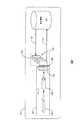
図6A及び図6Bは、一実施形態における図5の冷却システム500の模式図である。冷却システム500は、受入要素130を有する支持部材120、流路140、流体制御機構160、並びに冷却ピン配列要素232及び噛合要素234を有する熱部材230を具備した組立体100を備える。図6Aに示すように、冷却システム500は、ヒートシンク610、ヒートパイプ630、及び熱交換器640をさらに備えている。図6Bは、一実施形態における図6Aの冷却システム500の拡大図である。図6Bの冷却システム500は、サーバ筐体内のサーバ等の電子装置620を含んでいる。 6A and 6B are schematic diagrams of the
図6A及び図6Bを参照すると、ヒートシンク610は、ヒートパイプ630に接続されている。ヒートパイプ630は、電子装置620からの熱を除去するようになっている。また、ヒートパイプ630は、当該ヒートパイプ630の熱を冷ます伝熱ブロック650又は集熱板に接続されている。伝熱ブロック650は、熱部材230の噛合要素234に繋がっている。伝熱ブロック650及び熱部材230の噛合要素234の間の接続は、ドライディスコネクト660となっている。図6Bに示すドライディスコネクト660は、噛合要素234の表面と伝熱ブロック650の表面との接触により、両者間で熱を伝達する。伝熱ブロック650及び熱部材230の間で流体310が交換されないために、これをドライディスコネクトと称するものとする。熱は、流体交換ではなく、表面を介した伝導によって伝達されるようになっている。 Referring to FIGS. 6A and 6B, the
冷却システム500は、ヒートパイプ630における電子装置の損傷の危険性が非常に低い状態で、少量の流体を用いることによって、電子装置からの熱を除去することができる。図2〜図4Bに図示しながら上述した通り、電子装置からの熱は、その後、熱部材230に伝達されて液体冷却を施される。液体冷却は電子装置から離れて行われるために、効率的な冷却が可能であり、電子装置内における漏れの危険性を低減可能である。例えば、サーバにおいては、サーバ単位ではなくラック単位で液体冷却が行われる。このような熱が、サーバ内における流体310の漏れの危険性なく、中央処理演算ユニット等の電子装置からサーバの外表面に運ばれることとなる。そして、サーバレベルではなくラック単位、すなわち、個々の各サーバ内に設けられる構成要素において、液体冷却が行われる。ラック単位での液体冷却によって、液体冷却による漏れに起因する損傷からサーバを保護することができる。 The
伝熱ブロック650からの熱は、支持部材120、すなわち、受入要素130に接続された熱部材230を介して流体310に伝達される。上述の図2〜図4Bに示すように、流体310は、流入路部242に流入して冷却路部244を流れることによって、冷却ピン配列要素232を介して熱部材230からの熱を受ける。この熱は、熱部材230から流体310に伝達される。例えば、冷却ピン配列要素232は、流入部材352及び流入路部242を介して、流体310、すなわち、低温の流体を受け入れる。流体310は冷却ピン配列要素232を覆うように流れ、熱が流体310に伝達される。流体310、すなわち、高温の流体は、流出路部246及び流出部材354を介して、熱部材230から支持部材120の外部に除去されることとなる。 Heat from the
組立体100は、流体310からの熱を除去する熱交換器640等の冷却機構に接続されてもよい。例えば、この冷却機構は、サーバラック及び/又は当該サーバラックとは別の冷却設備に配置又は取り付けられた熱交換器640であってもよい。冷却機構は、流出部材354及び流入部材352の間において、支持部材120、すなわち、受入要素130に接続され、流出路部246からの流体310を再循環させると共に流入路部242に低温の流体310を提供する。例えば、熱交換器640が、流出路部246からの流体310の温度を低下させ、この低温の流体310を流入路部242に送る。このように、流体310は再利用可能であり、液体冷却プロセスは、再循環された流体310を用いて継続するようになっていてもよい。 The
図7は、一実施形態における図5の冷却システム500の斜視図である。冷却システム500は、サーバ筐体内のサーバ等の電子装置620からの熱のヒートシンク610における集まり方を図示している。この熱は、ヒートパイプ630を介してヒートシンク610を離れ、ヒートパイ630から、電子装置620及び熱部材230の間にドライディスコネクト660を提供する伝熱ブロック650に伝達される。例えば、ドライディスコネクト660は、サーバと、上述の通り支持部材120、受入要素130、流路140、及び熱部材230を備えたサーバラック705との間に設けられている。 FIG. 7 is a perspective view of the
図3、図6A、及び図6Bに示すように、熱は熱部材230に伝達される。この熱は、冷却ピン配列要素232によって、熱部材230から流体310に伝達され、例えば、高温の流体310と共に熱部材230から出ていくこととなる。高温の流体310は、例えば図3の流出部材354を介して組立体100から除去される。図7を再び参照すると、流体310は、組立体100から除去されると、熱交換器640等の冷却機構を用いて流体310から熱を除去する冷却設備に送られる(符号710)。熱除去後の流体310、例えば、低温の流体310は、プロセスの反復時に、例えば、図3の流入部材352を介して流入路部242に戻され(符号720)、熱部材230を通過する。 As shown in FIGS. 3, 6 </ b> A, and 6 </ b> B, heat is transferred to the
冷却システム500のモジュール式設計によって、製造、組み立て、及び保守が簡素化される。例えば、電子装置は、支持部材120及び熱部材230と並んだ伝熱ブロック650を備えている。ヒートパイプ630、ヒートシンク610等、電子装置のその他の態様は、変更されてもよく、相互に交換可能であってもよい。さらに、冷却システム500のモジュール特性によって、他のサーバに影響を及ぼすことなく1つのサーバを除去可能となる等、電子装置の保守がより簡単になる。 The modular design of the
図8は、一実施形態における電子装置を冷却する方法のフローチャート800である。この方法は、冷却システムと併用可能である。ブロック820において、冷却システムは電子装置からの熱を受ける。冷却システムは、支持部材、流路、流体制御機構、及び熱部材を備えている。支持部材は、熱部材を支持するようになっている。流路は、支持部材内に形成され、かつ流体を運ぶようになっている。流路は、流体を受け入れて、熱部材全体に流体を提供及び/又は分配して、熱部材から流体を除去するようになっている。流体制御機構は、流路に沿って流体の流れを制御するように構成されている。 FIG. 8 is a
熱部材は、電子装置からの熱を受ける伝熱ブロックに隣接して位置決めされ、全体で流体を受け入れるようになっている。熱部材は、支持部材側に延びる冷却ピン配列要素を有している。また、熱部材は、伝熱ブロックからの熱を除去するようになっている。例えば、冷却ピン配列要素が熱部材の一方側に位置決めされ、噛合要素が反対側に位置決めされている。噛合要素は、伝熱ブロックからの熱を受けるように位置決めされている。冷却ピン配列要素は、流体が存在して当該冷却ピン配列要素と接触している場合に、熱を流体に伝達するようになっている。 The thermal member is positioned adjacent to the heat transfer block that receives heat from the electronic device and is adapted to receive the fluid as a whole. The heat member has a cooling pin array element extending toward the support member. The heat member is adapted to remove heat from the heat transfer block. For example, the cooling pin array element is positioned on one side of the thermal member and the meshing element is positioned on the opposite side. The engagement element is positioned to receive heat from the heat transfer block. The cooling pin array element is adapted to transfer heat to the fluid when the fluid is present and in contact with the cooling pin array element.
ブロック840においては、流体は冷却システムに分配される。流体は、熱部材から熱を除去するため、流路を介して熱部材を覆うように分配される。また、流体は、冷却ピン配列要素を覆うように分配される。流体が冷却ピン配列要素に接触すると、熱が熱部材から流体に伝達される。ブロック860において、熱を帯びた流体(すなわち、高温の流体)は、冷却システムから除去される。流体は、流路を介して熱部材から除去された後、流出部材を通って支持部材から除去されてもよい。 In
この方法では、例えば、熱交換器を用いることによって、流体を再利用又は再循環するようになっていてもよい。流体は、流路及び流出部材を介して、熱部材から支持部材の外部に向かって、熱交換器まで運ばれる。熱交換器は、流体の温度を低下させる。そして、流体は、流路に戻され、流入部材を介して熱部材全体に分配されることとなる。 In this method, the fluid may be reused or recirculated, for example, by using a heat exchanger. The fluid is conveyed from the heat member to the outside of the support member through the flow path and the outflow member to the heat exchanger. The heat exchanger reduces the temperature of the fluid. Then, the fluid is returned to the flow path and is distributed to the entire heat member via the inflow member.
以上、非限定的かつ詳細な実施形態の記載によって本開示を説明したが、これは、本開示の範囲を限定するものではない。一実施形態に関して記載した特徴及び/又は動作は、他の実施形態に用いられてもよく、本開示のすべての実施形態が、特定の図面に図示若しくは実施形態のうち1つに関して記載した特徴及び/又は動作のすべてを有することはないものと理解すべきである。当業者には、記載した実施形態の変形例が想到されるであろう。さらに、用語「備える(具備する)」、「含む」、「有する」、及びこれらの活用形は、本開示及び/又は特許請求の範囲での使用に際して、「〜を含むが、必ずしもそれに限定されない」を意味するものとする。 As mentioned above, although this indication was described by description of non-limiting and detailed embodiment, this does not limit the range of this indication. Features and / or actions described with respect to one embodiment may be used with other embodiments, and all embodiments of the present disclosure are illustrated and described with reference to one of the embodiments and It should be understood that it does not have all of the actions. Those skilled in the art will envision variations on the described embodiments. Further, the terms “comprising”, “including”, “having”, and their conjugations, as used in the present disclosure and / or claims, include “but are not necessarily limited to”. ".
上述の実施形態のいくつかは、本開示に必須とは考えられない構造、作用、又は構造及び作用の詳細を含む場合があり、一例として示したものであることに留意されたい。本明細書に記載の構造及び作用は、本技術分野で周知の構造又は作用と異なっていても、同じ機能を果たす均等物によって置き換え可能である。従って、本開示の範囲は、特許請求の範囲に用いられている要素及び制約によってのみ制限されるものである。
It should be noted that some of the above-described embodiments may include structures, operations, or details of structures and operations that are not considered essential to this disclosure, and are given as examples. Structures and acts described herein may be replaced by equivalents that perform the same function, even if they differ from structures or acts well known in the art. Accordingly, the scope of the present disclosure is limited only by the elements and limitations used in the claims.
Claims (14)
Translated fromJapanese一方側の冷却ピン配列要素及び反対側の噛合要素を有する熱部材と、
該熱部材を支持する支持部材であって、前記熱部材を受け入れるように形成されると共に前記熱部材に接続される受入要素を有する支持部材と、
該支持部材に形成され、かつ流体を運ぶように構成される流路であって、前記流体を受け入れて、前記熱部材の全体に前記流体を分配して、さらに、前記熱部材から前記流体を除去するように構成される流路と、
前記流路に沿って前記流体の流れを制御するように構成される流体制御機構と
を備え、
前記冷却ピン配列要素が、前記熱部材から前記受入要素に向かって延び、かつその全体に渡って前記流体を受け入れるように構成され、
前記噛合要素が、伝熱ブロックに隣接する位置であって、前記伝熱ブロックが前記噛合要素を介して電子装置から前記熱部材に熱を伝達し、さらに、前記流体が前記冷却ピン配列要素と接触して当該熱を除去する、位置に配置されている、組立体。In assemblies that can be used with cooling systems,
A thermal member having a cooling pin array element on one side and a mating element on the opposite side;
A support member for supportingthe heat member, a support member having a receivingelement connected to Rutotomoni the heat member is formed to receivethe heat member,
Is formed in the support member, and a composed channel to carry fluid, it receives the fluid, the fluid is distributed throughoutthe heat member, further, the fluid fromthe heat member A flow path configured to remove;
A fluid control mechanism configured to control flow of the fluid along the flow path;
The cooling pin array element extends from the thermal member toward the receiving element and is configured to receive the fluid throughout.
The meshing element is located adjacent to the heat transfer block, the heat transfer block transfers heat from the electronic device to the heat member via the meshing element, and the fluid is connected to the cooling pin array element. An assemblydisposed in a position that contacts and removes the heat .
前記流体を受け入れて前記熱部材の全体に分配するように構成される流入路部と、
前記熱部材に接続可能とすると共に前記熱部材から前記流体を除去するように構成される流出路部と、
前記流入路部及び前記流出路部間で延び、かつ前記熱部材の全体に前記流体を運ぶように構成される冷却路部と
をさらに有している、請求項1に記載の組立体。The flow path is
When configured inflow channel portion so as to distribute the whole ofthe heat member by receiving the fluid,
An outflow passage that isconnectable to the thermal member and configured to remove the fluid from the thermal member;
The extending between inlet passage portion and the outlet channel section, and further has a cooling passage section configured throughout carrying the fluid ofthe heat member assembly according to claim 1.
前記ワックス部材が前記熱部材中の前記流体の温度上昇に伴って膨張し、かつ前記ワックス部材の膨張によって前記弁体が前記熱部材に進入可能となることによって、前記熱部材の全体を流れる前記流体の量が増加するように構成され、
前記ワックス部材が前記熱部材中の前記流体の温度低下に伴って収縮し、かつ前記ワックス部材の収縮によって前記弁体が退避可能となることによって、前記支持部材の全体を流れる前記流体の量が減少するように構成されている請求項4に記載の組立体。The thermally actuated valve includes a valve fitting, a valve body having a wax member that receives the valve fitting, and an elastic member that controls movement of the valve body by expansion and contraction,
The wax member expands as the temperature of the fluid in the thermal member rises, and the valve member can enter the thermal member due to the expansion of the wax member, so that the whole of the thermal member flows. Configured to increase the amount of fluid,
The amount of the fluid flowing through the entire support member is reduced when the wax member contracts as the temperature of the fluid in the heat member decreases and the valve member can be retracted by the contraction of the wax member. The assembly ofclaim 4 , wherein the assembly is configured to decrease.
前記支持部材に形成され、かつ前記流体を運ぶように構成される流路であって、前記流体を受け入れて前記複数の熱部材の全体に分配するように構成される流入路部、及び前記複数の熱部材のそれぞれに接続可能とすると共に前記複数の熱部材から前記流体を除去するように構成される流出路部を有する流路と、
該流路内に位置し、かつ前記複数の熱部材の全体に渡って前記流体の流れを制御するように構成される流体制御機構と
を備えている冷却システム。A support member for supporting a plurality of thermal members, wherein a plurality of receiving elements are formed on the support member, and each of the plurality of receiving elements is configured to receive one of the plurality of thermal members. Each of the plurality of thermal members has a cooling pin array element, the cooling pin array element extending from each of the plurality of heat members toward the corresponding receiving element, and fluid throughout A support member configured to receive and remove heat;
A flow path formed in the support member and configured to carry the fluid, the inflow path configured to receive and distribute the fluid throughout the plurality of thermal members; and the plurality A flow path having an outflow path configured to be connectable to each of the thermal members and to remove the fluid from the plurality of thermal members;
And a fluid control mechanism configured to control the flow of the fluid over the whole of the plurality of thermal members.
前記冷却ピン配列要素が前記複数の熱部材のそれぞれにおける一方側に配置され、
前記噛合要素が前記複数の熱部材のそれぞれにおける反対側に配置され、
前記1つの熱部材が、伝熱ブロックに隣接する位置であって、前記伝熱ブロックが前記噛合要素を介して電子装置から前記1つの熱部材に熱を伝達し、かつ前記流体が前記冷却ピン配列要素と接触して前記複数の熱部材のそれぞれから前記流体に当該熱を伝達する、位置に配置されている、請求項7に記載の冷却システム。Each of the plurality of thermal members further has an engagement element,
The cooling pin array element is disposed on one side of each of the plurality of thermal members;
The engagement element is disposed on an opposite side of each of the plurality of thermal members;
The one heat member is located adjacent to the heat transfer block, the heat transfer block transfers heat from the electronic device to the one heat member via the engagement element, and the fluid is the cooling pin. The cooling system according toclaim 7 , wherein the cooling system is disposed at a position in contact with an array element to transfer the heat from each of the plurality of thermal members to the fluid.
前記流体を除去するように構成される流出部材と
をさらに備えている請求項7に記載の冷却システム。An inflow member configured to receive the fluid;
The cooling system ofclaim 7 , further comprising an outflow member configured to remove the fluid.
前記複数の冷却路部のそれぞれが、前記複数の受入要素のうち1つの受入要素及び前記複数の熱部材のうち1つの熱部材間に形成されることによって、前記流体が前記複数の熱部材の全体に分配されるように構成されている請求項7に記載の冷却システム。A plurality of cooling passages extending between the inflow passage and the outflow passage;
Each of the plurality of cooling path portions is formed between one receiving element of the plurality of receiving elements and one thermal member of the plurality of thermal members, so that the fluid is The cooling system ofclaim 7 , wherein the cooling system is configured to be distributed throughout.
前記熱作動弁が、弁取付具、該弁取付具を受け入れるように構成されるワックス部材を有する弁体、及び伸縮により前記弁体の移動を制御するように構成される弾性部材を含み、
前記ワックス部材が前記1つの熱部材における前記流体の温度上昇に伴って膨張し、かつ前記ワックス部材の膨張によって前記弁体が前記1つの熱部材に進入可能となることによって、前記1つの熱部材の全体を流れる前記流体の量が増加するように構成され、
前記ワックス部材が前記1つの熱部材における前記流体の温度低下に伴って収縮し、かつ前記ワックス部材の収縮によって前記弁体が退避可能となることによって、前記支持部材全体を流れる前記流体の量が減少するように構成されている請求項7に記載の冷却システム。In order to control the temperature of the fluid based on the temperature of the fluid flowing through the cooling pin array element in the one thermal member, further providing at least one thermal actuation valve for each of the plurality of thermal members, Configured to adjust the temperature of the fluid;
The thermally actuated valve includes a valve fitting, a valve body having a wax member configured to receive the valve fitting, and an elastic member configured to control movement of the valve body by expansion and contraction;
When the wax member expands as the temperature of the fluid in the one heat member rises, and the valve member can enter the one heat member due to the expansion of the wax member, the one heat member Configured to increase the amount of fluid flowing through
The amount of the fluid flowing through the entire support member is reduced when the wax member contracts as the temperature of the fluid in the one heat member decreases and the valve member can be retracted by the contraction of the wax member. The cooling system ofclaim 7 , wherein the cooling system is configured to decrease.
前記電子装置からの熱を冷却システムにより受けるステップであって、前記冷却システムが、熱部材を支持する支持部材と、該支持部材に形成され、かつ流体を運ぶように構成される流路であって、前記流体を受け入れ、前記熱部材の全体に前記流体を分配し、さらに、前記熱部材から前記流体を除去するように構成される流路と、該流路に沿って前記流体の流れを制御するように構成される流体制御機構と、前記電子装置からの熱を受ける伝熱ブロックに隣接して配置される熱部材であって、冷却ピン配列要素を一方側に設け、かつ該冷却ピン配列要素を前記受入要素に向かって延びるように形成した熱部材とを備える、ステップと、
前記流路を介して前記流体を前記熱部材の全体に分配するステップであって、前記流体が前記冷却ピン配列要素を覆うように分配され、かつ前記流体及び前記冷却ピン配列要素の接触に伴って前記熱が前記熱部材から前記流体に伝達される、ステップと、
前記流路を介して前記熱を帯びた前記流体を前記熱部材から除去するステップと
を含む方法。A method for cooling an electronic device, comprising:
Receiving a heat from the electronic device by a cooling system, the cooling system comprising: a support member that supports the heat member; and a flow path formed on the support member and configured to carry a fluid. A flow path configured to receive the fluid, distribute the fluid throughout the thermal member, and remove the fluid from the thermal member; and a flow of the fluid along the flow path. A fluid control mechanism configured to control and a heat member disposed adjacent to a heat transfer block that receives heat from the electronic device, the cooling pin array element being provided on one side, and the cooling pin A thermal member formed to extend an array element toward the receiving element;
Distributing the fluid over the heat member via the flow path, the fluid being distributed over the cooling pin array element and accompanying the contact of the fluid and the cooling pin array element The heat is transferred from the thermal member to the fluid;
Removing the heated fluid from the thermal member via the flow path.
Applications Claiming Priority (1)
| Application Number | Priority Date | Filing Date | Title |
|---|---|---|---|
| PCT/US2012/057739WO2014051604A1 (en) | 2012-09-28 | 2012-09-28 | Cooling assembly |
Publications (2)
| Publication Number | Publication Date |
|---|---|
| JP2015532528A JP2015532528A (en) | 2015-11-09 |
| JP6112640B2true JP6112640B2 (en) | 2017-04-12 |
Family
ID=50388793
Family Applications (1)
| Application Number | Title | Priority Date | Filing Date |
|---|---|---|---|
| JP2015534447AExpired - Fee RelatedJP6112640B2 (en) | 2012-09-28 | 2012-09-28 | Cooling assembly |
Country Status (6)
| Country | Link |
|---|---|
| US (2) | US9927187B2 (en) |
| EP (1) | EP2901828A4 (en) |
| JP (1) | JP6112640B2 (en) |
| CN (1) | CN104685984A (en) |
| TW (1) | TWI549597B (en) |
| WO (1) | WO2014051604A1 (en) |
Cited By (1)
| Publication number | Priority date | Publication date | Assignee | Title |
|---|---|---|---|---|
| RU2702138C1 (en)* | 2018-12-24 | 2019-10-04 | Антон Андреевич Румянцев | Electronic units cooling system |
Families Citing this family (10)
| Publication number | Priority date | Publication date | Assignee | Title |
|---|---|---|---|---|
| US10123464B2 (en) | 2012-02-09 | 2018-11-06 | Hewlett Packard Enterprise Development Lp | Heat dissipating system |
| JP6112640B2 (en) | 2012-09-28 | 2017-04-12 | ヒューレット パッカード エンタープライズ デベロップメント エル ピーHewlett Packard Enterprise Development LP | Cooling assembly |
| BR112015018354A2 (en)* | 2013-01-31 | 2017-07-18 | Hewlett Packard Development Co | liquid cooling |
| JP2015012282A (en)* | 2013-07-02 | 2015-01-19 | 富士通株式会社 | Electronic equipment |
| CN106134304B (en)* | 2014-05-15 | 2019-07-23 | 慧与发展有限责任合伙企业 | Fluid manifold |
| TWI739574B (en)* | 2020-08-31 | 2021-09-11 | 技嘉科技股份有限公司 | Water block |
| CN114126324A (en)* | 2020-08-31 | 2022-03-01 | 技嘉科技股份有限公司 | water block |
| TWI806374B (en) | 2022-01-19 | 2023-06-21 | 緯創資通股份有限公司 | Flow path module, coolant distribution device and server |
| US12130677B2 (en)* | 2022-04-07 | 2024-10-29 | Dell Products L.P. | Multi-device-chassis/device movable coupling liquid cooling system |
| EP4152905B1 (en)* | 2022-08-18 | 2025-04-23 | Ovh | Immersion-cooled electronic device and cooling monitoring system for immersion-cooled electronic device |
Family Cites Families (226)
| Publication number | Priority date | Publication date | Assignee | Title |
|---|---|---|---|---|
| US2115501A (en) | 1934-10-01 | 1938-04-26 | Vernay Patents Company | Thermostat |
| US2115001A (en) | 1935-10-29 | 1938-04-26 | United Res Corp | Sound reproduction |
| US2582553A (en) | 1949-08-17 | 1952-01-15 | Ferdinand Furniture Company In | Sectional toy furniture |
| US3279876A (en) | 1964-07-30 | 1966-10-18 | Mutschler Brothers Company | Storage cabinet construction |
| US3807572A (en) | 1972-05-12 | 1974-04-30 | Pitney Bowes Inc | Adjustable compartment size storage unit |
| US4453785A (en) | 1980-04-07 | 1984-06-12 | Smith Richard D | Modular cabinet for different video game cartridges, cassettes, and instruction booklets |
| US4714107A (en) | 1981-03-05 | 1987-12-22 | International Laser Systems, Inc. | Titanium heat exchanger for laser cooling |
| FR2586335B1 (en) | 1985-08-14 | 1989-04-28 | Snecma | AVIATION TURBOMACHINE COMPUTER SUPPORT |
| JPS6391376A (en) | 1986-10-06 | 1988-04-22 | Takeda Chem Ind Ltd | Sulfonylisothiourea derivative |
| US4883225A (en) | 1988-03-18 | 1989-11-28 | S.T.C., Inc. | Fail-safe thermostat for vehicular cooling systems |
| JPH02300890A (en) | 1989-05-15 | 1990-12-13 | Fuji Electric Co Ltd | Attachment structure of rack partitioning plate for vending machine |
| US5228385A (en) | 1992-03-03 | 1993-07-20 | Friedrich Metal Products Co., Inc. | Convection oven for bakery goods |
| US5370178A (en) | 1993-08-25 | 1994-12-06 | International Business Machines Corporation | Convertible cooling module for air or water cooling of electronic circuit components |
| US5514906A (en) | 1993-11-10 | 1996-05-07 | Fujitsu Limited | Apparatus for cooling semiconductor chips in multichip modules |
| US5417012A (en) | 1993-11-23 | 1995-05-23 | Digital Equipment Corporation | Equipment cabinet door mountable on either side and having a central latch |
| US5505533A (en) | 1994-01-10 | 1996-04-09 | Artecon | Rackmount for computer and mass storage enclosure |
| US5918469A (en) | 1996-01-11 | 1999-07-06 | Silicon Thermal, Inc. | Cooling system and method of cooling electronic devices |
| US6333849B1 (en) | 1996-07-01 | 2001-12-25 | Compaq Computer Corporation | Apparatus for liquid cooling of specific computer components |
| US6111749A (en) | 1996-09-25 | 2000-08-29 | International Business Machines Corporation | Flexible cold plate having a one-piece coolant conduit and method employing same |
| US5964092A (en) | 1996-12-13 | 1999-10-12 | Nippon Sigmax, Co., Ltd. | Electronic cooling apparatus |
| US5867369A (en) | 1997-07-15 | 1999-02-02 | Sun Microsystems, Inc. | Rugged computer housing |
| US5982616A (en) | 1997-08-20 | 1999-11-09 | Compaq Computer Corporation | Electronic apparatus with plug-in heat pipe module cooling system |
| US6084769A (en) | 1997-08-20 | 2000-07-04 | Compaq Computer Corporation | Docking station with auxiliary heat dissipation system for a docked portable computer |
| US5986882A (en) | 1997-10-16 | 1999-11-16 | Compaq Computer Corporation | Electronic apparatus having removable processor/heat pipe cooling device modules therein |
| US5829514A (en) | 1997-10-29 | 1998-11-03 | Eastman Kodak Company | Bonded cast, pin-finned heat sink and method of manufacture |
| JPH11220281A (en) | 1998-01-30 | 1999-08-10 | Nec Eng Ltd | Sealing structure between panel housing shelf |
| JP3315649B2 (en) | 1998-08-11 | 2002-08-19 | 富士通株式会社 | Electronics |
| JP2000076537A (en) | 1998-08-31 | 2000-03-14 | Toshiba Corp | vending machine |
| US6234842B1 (en) | 1998-11-20 | 2001-05-22 | Vlt Corporation | Power converter connector assembly |
| JP3430941B2 (en) | 1998-12-04 | 2003-07-28 | コクヨ株式会社 | Shelf partition structure |
| US6377453B1 (en) | 1999-01-29 | 2002-04-23 | Hewlett-Packard Company | Field replaceable module with enhanced thermal interface |
| US5971166A (en) | 1999-02-16 | 1999-10-26 | Ong; Bon S. | Hanging box file with compartments |
| GB2354062A (en) | 1999-09-13 | 2001-03-14 | British Broadcasting Corp | Cooling system for use in cooling electronic equipment |
| JP2001168256A (en)* | 1999-12-13 | 2001-06-22 | Sumitomo Electric Ind Ltd | Heat dissipation structure for semiconductor element and semiconductor device having the same |
| WO2001072099A2 (en) | 2000-03-21 | 2001-09-27 | Liebert Corporation | Method and apparatus for cooling electronic enclosures |
| US6578626B1 (en) | 2000-11-21 | 2003-06-17 | Thermal Corp. | Liquid cooled heat exchanger with enhanced flow |
| US6498725B2 (en) | 2001-05-01 | 2002-12-24 | Mainstream Engineering Corporation | Method and two-phase spray cooling apparatus |
| DE10296928T5 (en) | 2001-06-12 | 2004-10-07 | Liebert Corp | Single or double bus heat transfer system |
| CN2519983Y (en) | 2001-11-30 | 2002-11-06 | 施水源 | Server with four parallel hard disks |
| US7133283B2 (en) | 2002-01-04 | 2006-11-07 | Intel Corporation | Frame-level thermal interface component for transfer of heat from an electronic component of a computer system |
| US6594148B1 (en) | 2002-01-16 | 2003-07-15 | Cisco Technology, Inc. | Airflow system |
| US7024573B2 (en) | 2002-02-05 | 2006-04-04 | Hewlett-Packard Development Company, L.P. | Method and apparatus for cooling heat generating components |
| US6879486B1 (en) | 2002-02-14 | 2005-04-12 | Mercury Computer Systems, Inc. | Central inlet circuit board assembly |
| EP1481467B1 (en) | 2002-03-05 | 2010-06-09 | Sri International | Electroactive polymer devices for controlling fluid flow |
| DE10210480B4 (en) | 2002-03-11 | 2005-07-21 | Rittal Gmbh & Co. Kg | cooling arrangement |
| DK174881B1 (en) | 2002-05-08 | 2004-01-19 | Danfoss Silicon Power Gmbh | Multiple cooling cell device for cooling semiconductors |
| US6600649B1 (en) | 2002-05-24 | 2003-07-29 | Mei-Nan Tsai | Heat dissipating device |
| US6704198B2 (en) | 2002-06-12 | 2004-03-09 | Avava Technology Corp. | Equipment enclosure with heat exchanger |
| US6880626B2 (en) | 2002-08-28 | 2005-04-19 | Thermal Corp. | Vapor chamber with sintered grooved wick |
| JP3757200B2 (en) | 2002-09-25 | 2006-03-22 | 株式会社日立製作所 | Electronic equipment with cooling mechanism |
| JP4199018B2 (en) | 2003-02-14 | 2008-12-17 | 株式会社日立製作所 | Rack mount server system |
| JP2004295718A (en) | 2003-03-28 | 2004-10-21 | Hitachi Ltd | Liquid example system for information processing equipment |
| US20040201335A1 (en) | 2003-03-28 | 2004-10-14 | Brooks Davis | Universal computer enclosure |
| US7112131B2 (en) | 2003-05-13 | 2006-09-26 | American Power Conversion Corporation | Rack enclosure |
| US7085133B2 (en) | 2003-07-09 | 2006-08-01 | International Business Machines Corporation | Cooling using complimentary tapered plenums |
| JP2005064186A (en) | 2003-08-11 | 2005-03-10 | Hitachi Ltd | Electronic equipment with cooling system |
| US6987673B1 (en) | 2003-09-09 | 2006-01-17 | Emc Corporation | Techniques for cooling a set of circuit boards within a rack mount cabinet |
| US7044199B2 (en) | 2003-10-20 | 2006-05-16 | Thermal Corp. | Porous media cold plate |
| ES2537764T3 (en) | 2003-11-07 | 2015-06-11 | Asetek A/S | Cooling system for a computer system |
| US7106590B2 (en) | 2003-12-03 | 2006-09-12 | International Business Machines Corporation | Cooling system and method employing multiple dedicated coolant conditioning units for cooling multiple electronics subsystems |
| US20050128705A1 (en) | 2003-12-16 | 2005-06-16 | International Business Machines Corporation | Composite cold plate assembly |
| US7508663B2 (en) | 2003-12-29 | 2009-03-24 | Rackable Systems, Inc. | Computer rack cooling system with variable airflow impedance |
| JP2005228216A (en) | 2004-02-16 | 2005-08-25 | Hitachi Ltd | Electronics |
| TWM254049U (en) | 2004-03-03 | 2004-12-21 | Mitac Int Corp | Free of screw structure for top cover of server case |
| US20050199372A1 (en) | 2004-03-08 | 2005-09-15 | Frazer James T. | Cold plate and method of making the same |
| US7647787B2 (en) | 2004-04-22 | 2010-01-19 | Hewlett-Packard Development Company, L.P. | Upgradeable, modular data center cooling apparatus |
| US7460375B2 (en) | 2004-05-07 | 2008-12-02 | Rackable Systems, Inc. | Interface assembly |
| US7529097B2 (en) | 2004-05-07 | 2009-05-05 | Rackable Systems, Inc. | Rack mounted computer system |
| US7236370B2 (en) | 2004-05-07 | 2007-06-26 | Rackable Systems, Inc. | Computer rack with cluster modules |
| US7372695B2 (en) | 2004-05-07 | 2008-05-13 | Rackable Systems, Inc. | Directional fan assembly |
| US7187549B2 (en) | 2004-06-30 | 2007-03-06 | Teradyne, Inc. | Heat exchange apparatus with parallel flow |
| US7019974B2 (en) | 2004-07-16 | 2006-03-28 | Hon Hai Precision Industry Co., Ltd. | Heat dissipation device |
| US7405932B2 (en) | 2004-07-19 | 2008-07-29 | Hewlett-Packard Development Company, L.P. | System and method for cooling electronic devices |
| US7380409B2 (en) | 2004-09-30 | 2008-06-03 | International Business Machines Corporation | Isolation valve and coolant connect/disconnect assemblies and methods of fabrication for interfacing a liquid cooled electronics subsystem and an electronics housing |
| JP4312235B2 (en) | 2004-11-16 | 2009-08-12 | 富士通株式会社 | Communication device and rack structure |
| US7184269B2 (en) | 2004-12-09 | 2007-02-27 | International Business Machines Company | Cooling apparatus and method for an electronics module employing an integrated heat exchange assembly |
| US7218129B2 (en) | 2005-01-12 | 2007-05-15 | International Business Machines Corporation | System, apparatus and method for controlling temperature of an integrated circuit under test |
| CN101111734B (en) | 2005-02-02 | 2010-05-12 | 开利公司 | Parallel flow heat exchangers incorporating porous inserts |
| JP2006215882A (en) | 2005-02-04 | 2006-08-17 | Hitachi Ltd | Disk array device and liquid cooling device thereof |
| US7286345B2 (en) | 2005-02-08 | 2007-10-23 | Rackable Systems, Inc. | Rack-mounted air deflector |
| US7385810B2 (en) | 2005-04-18 | 2008-06-10 | International Business Machines Corporation | Apparatus and method for facilitating cooling of an electronics rack employing a heat exchange assembly mounted to an outlet door cover of the electronics rack |
| WO2006115073A1 (en) | 2005-04-21 | 2006-11-02 | Nippon Light Metal Company, Ltd. | Liquid-cooled jacket |
| CN100499089C (en) | 2005-06-08 | 2009-06-10 | 富准精密工业(深圳)有限公司 | Radiator |
| CN100455175C (en) | 2005-07-08 | 2009-01-21 | 富准精密工业(深圳)有限公司 | Loop-type radiating module group |
| CN1913760A (en) | 2005-08-12 | 2007-02-14 | 鸿富锦精密工业(深圳)有限公司 | Liquid-cooled radiation system |
| US7393236B2 (en) | 2005-09-02 | 2008-07-01 | Gm Global Technology Operations, Inc. | Integrated thermal and electrical connection system for power devices |
| US7652889B2 (en) | 2005-10-25 | 2010-01-26 | Hewlett-Packard Development Company, L.P. | Information technology (IT) equipment position locating system using jumper connections |
| US7487397B2 (en) | 2005-10-27 | 2009-02-03 | International Business Machines Corporation | Method for cache correction using functional tests translated to fuse repair |
| JP4826887B2 (en) | 2005-10-28 | 2011-11-30 | 中村製作所株式会社 | Electronic component package with liquid-cooled heat exchanger and method for forming the same |
| US8079481B2 (en) | 2005-10-28 | 2011-12-20 | International Business Machines Corporation | Integrated frame and central electronic complex structure |
| US7900692B2 (en)* | 2005-10-28 | 2011-03-08 | Nakamura Seisakusho Kabushikigaisha | Component package having heat exchanger |
| US8051897B2 (en) | 2005-11-30 | 2011-11-08 | International Business Machines Corporation | Redundant assembly for a liquid and air cooled module |
| US7558074B2 (en) | 2006-02-14 | 2009-07-07 | Super Micro Computer, Inc. | Partitioning device for holding slots of a host computer case |
| US7539020B2 (en) | 2006-02-16 | 2009-05-26 | Cooligy Inc. | Liquid cooling loops for server applications |
| DE202006003754U1 (en) | 2006-03-09 | 2006-05-04 | Knürr AG | heat exchangers |
| US7718891B2 (en) | 2006-03-13 | 2010-05-18 | Panduit Corp. | Network cabinet |
| US7870893B2 (en)* | 2006-04-06 | 2011-01-18 | Oracle America, Inc. | Multichannel cooling system with magnetohydrodynamic pump |
| US7715194B2 (en) | 2006-04-11 | 2010-05-11 | Cooligy Inc. | Methodology of cooling multiple heat sources in a personal computer through the use of multiple fluid-based heat exchanging loops coupled via modular bus-type heat exchangers |
| US7298619B1 (en) | 2006-05-02 | 2007-11-20 | Hewlett-Packard Development Company, L.P. | Cable management arm with integrated heat exchanger |
| ITPD20060176A1 (en) | 2006-05-05 | 2007-11-06 | Liebert Hiross Spa | FURNISHED EQUIPMENT FOR RACKS CONDITIONING FOR ELECTRICAL, ELECTRONIC, TELECOMMUNICATION AND SIMILAR INSTRUMENTS |
| US7403392B2 (en) | 2006-05-16 | 2008-07-22 | Hardcore Computer, Inc. | Liquid submersion cooling system |
| EP1860695A3 (en)* | 2006-05-24 | 2010-06-16 | Raytheon Company | System and method of jet impingement cooling with extended surfaces |
| US7701714B2 (en) | 2006-05-26 | 2010-04-20 | Flextronics Ap, Llc | Liquid-air hybrid cooling in electronics equipment |
| US20100091449A1 (en) | 2006-06-01 | 2010-04-15 | Jimmy Clidaras | Modular Computing Environments |
| US8757246B2 (en) | 2006-06-06 | 2014-06-24 | Raytheon Company | Heat sink and method of making same |
| US20070291452A1 (en) | 2006-06-14 | 2007-12-20 | Gilliland Don A | Heat Transfer Systems for Dissipating Thermal Loads From a Computer Rack |
| US7768780B2 (en) | 2006-06-19 | 2010-08-03 | Silicon Graphics International Corp. | Flow-through cooling for computer systems |
| US20070297136A1 (en) | 2006-06-23 | 2007-12-27 | Sun Micosystems, Inc. | Modular liquid cooling of electronic components while preserving data center integrity |
| JP5283836B2 (en) | 2006-07-25 | 2013-09-04 | 富士通株式会社 | Heat receiver and liquid cooling unit for liquid cooling unit and electronic device |
| US7403384B2 (en) | 2006-07-26 | 2008-07-22 | Dell Products L.P. | Thermal docking station for electronics |
| US7447022B2 (en) | 2006-08-09 | 2008-11-04 | Hewlett-Packard Development Company, L.P. | Rack-mount equipment bay cooling heat exchanger |
| US8327656B2 (en) | 2006-08-15 | 2012-12-11 | American Power Conversion Corporation | Method and apparatus for cooling |
| US8322155B2 (en) | 2006-08-15 | 2012-12-04 | American Power Conversion Corporation | Method and apparatus for cooling |
| US7397661B2 (en) | 2006-08-25 | 2008-07-08 | International Business Machines Corporation | Cooled electronics system and method employing air-to-liquid heat exchange and bifurcated air flow |
| JP5247016B2 (en) | 2006-08-31 | 2013-07-24 | キヤノン株式会社 | Method for producing composite material and dispersant |
| US7856838B2 (en) | 2006-09-13 | 2010-12-28 | Oracle America, Inc. | Cooling air flow loop for a data center in a shipping container |
| US7450378B2 (en) | 2006-10-25 | 2008-11-11 | Gm Global Technology Operations, Inc. | Power module having self-contained cooling system |
| TWM312877U (en) | 2006-11-03 | 2007-05-21 | Hon Hai Prec Ind Co Ltd | Mounting assembly for disk drive bracket |
| SE530902C2 (en) | 2006-12-19 | 2008-10-14 | Alfa Laval Corp Ab | Sectioned flow device and method for controlling the temperature thereof |
| US7564685B2 (en) | 2006-12-29 | 2009-07-21 | Google Inc. | Motherboards with integrated cooling |
| US8453471B2 (en) | 2007-03-14 | 2013-06-04 | Zonit Structured Solutions, Llc | Air-based cooling for data center rack |
| JP5030631B2 (en) | 2007-03-22 | 2012-09-19 | 富士通株式会社 | Cooling system for information equipment |
| US20080239649A1 (en) | 2007-03-29 | 2008-10-02 | Bradicich Thomas M | Design structure for an interposer for expanded capability of a blade server chassis system |
| US7957132B2 (en) | 2007-04-16 | 2011-06-07 | Fried Stephen S | Efficiently cool data centers and electronic enclosures using loop heat pipes |
| US8118084B2 (en) | 2007-05-01 | 2012-02-21 | Liebert Corporation | Heat exchanger and method for use in precision cooling systems |
| US7688578B2 (en) | 2007-07-19 | 2010-03-30 | Hewlett-Packard Development Company, L.P. | Modular high-density computer system |
| TW200910068A (en) | 2007-08-20 | 2009-03-01 | Asustek Comp Inc | Heat dissipation apparatus |
| US7539013B2 (en) | 2007-09-27 | 2009-05-26 | International Business Machines Corporation | Automatic air blockage assembly and method for computing environments |
| US20090086456A1 (en) | 2007-09-27 | 2009-04-02 | Sun Microsystems, Inc. | Tool-less blade ejector latch with integrated spring |
| US7907402B2 (en) | 2007-11-09 | 2011-03-15 | Panduit Corp. | Cooling system |
| US7764494B2 (en) | 2007-11-20 | 2010-07-27 | Basic Electronics, Inc. | Liquid cooled module |
| US7916480B2 (en) | 2007-12-19 | 2011-03-29 | GM Global Technology Operations LLC | Busbar assembly with integrated cooling |
| KR100944890B1 (en) | 2008-01-14 | 2010-03-03 | 에버테크노 주식회사 | Test tray of the SSD test handler |
| US7808780B2 (en) | 2008-02-28 | 2010-10-05 | International Business Machines Corporation | Variable flow computer cooling system for a data center and method of operation |
| US20090225514A1 (en) | 2008-03-10 | 2009-09-10 | Adrian Correa | Device and methodology for the removal of heat from an equipment rack by means of heat exchangers mounted to a door |
| US7907409B2 (en)* | 2008-03-25 | 2011-03-15 | Raytheon Company | Systems and methods for cooling a computing component in a computing rack |
| US8164901B2 (en) | 2008-04-16 | 2012-04-24 | Julius Neudorfer | High efficiency heat removal system for rack mounted computer equipment |
| US7905106B2 (en) | 2008-04-21 | 2011-03-15 | Hardcore Computer, Inc. | Case and rack system for liquid submersion cooling of electronic devices connected in an array |
| JP5002522B2 (en) | 2008-04-24 | 2012-08-15 | 株式会社日立製作所 | Cooling device for electronic equipment and electronic equipment provided with the same |
| US10058011B2 (en) | 2008-06-19 | 2018-08-21 | Panduit Corp. | Passive cooling systems for network cabinet |
| KR20110027766A (en) | 2008-07-09 | 2011-03-16 | 휴렛-팩커드 디벨롭먼트 컴퍼니, 엘.피. | Dedicated air intake and air outlet for computer chassis chamber |
| JP2010041007A (en) | 2008-08-08 | 2010-02-18 | Hitachi Information & Communication Engineering Ltd | Cooling unit, electronic apparatus rack, cooling system, and construction method thereof |
| US20100032142A1 (en) | 2008-08-11 | 2010-02-11 | Sun Microsystems, Inc. | Liquid cooled rack with optimized air flow rate and liquid coolant flow |
| JP5023020B2 (en) | 2008-08-26 | 2012-09-12 | 株式会社豊田自動織機 | Liquid cooling system |
| US7983040B2 (en) | 2008-10-23 | 2011-07-19 | International Business Machines Corporation | Apparatus and method for facilitating pumped immersion-cooling of an electronic subsystem |
| US7916483B2 (en) | 2008-10-23 | 2011-03-29 | International Business Machines Corporation | Open flow cold plate for liquid cooled electronic packages |
| US7961475B2 (en) | 2008-10-23 | 2011-06-14 | International Business Machines Corporation | Apparatus and method for facilitating immersion-cooling of an electronic subsystem |
| US7885070B2 (en) | 2008-10-23 | 2011-02-08 | International Business Machines Corporation | Apparatus and method for immersion-cooling of an electronic system utilizing coolant jet impingement and coolant wash flow |
| US20120004172A1 (en) | 2008-10-27 | 2012-01-05 | Oncotherapy Science, Inc. | Screening method of anti-lung or esophageal cancer compounds |
| WO2010050933A1 (en)* | 2008-10-29 | 2010-05-06 | Advantest Corporation | Thermal controller for electronic devices |
| US20100110621A1 (en) | 2008-10-31 | 2010-05-06 | Liebert Corporation | Rack with vertical mounting providing room for rack pdu |
| US7724524B1 (en) | 2008-11-12 | 2010-05-25 | International Business Machines Corporation | Hybrid immersion cooled server with integral spot and bath cooling |
| US20100141379A1 (en) | 2008-12-05 | 2010-06-10 | Tucker Peter T | Modular Rack Controllers for Patching Systems |
| DE102008061489A1 (en) | 2008-12-10 | 2010-06-17 | Siemens Aktiengesellschaft | Power converter module with cooled busbar |
| US7990710B2 (en) | 2008-12-31 | 2011-08-02 | Vs Acquisition Co. Llc | Data center |
| US8305759B2 (en) | 2009-03-09 | 2012-11-06 | Hardcore Computer, Inc. | Gravity assisted directed liquid cooling |
| CN101509732A (en) | 2009-03-12 | 2009-08-19 | 华南理工大学 | Microchannel evaporator for uniformly distributing flow quantity |
| US8297069B2 (en) | 2009-03-19 | 2012-10-30 | Vette Corporation | Modular scalable coolant distribution unit |
| US20100248609A1 (en) | 2009-03-24 | 2010-09-30 | Wright Line, Llc | Assembly For Providing A Downflow Return Air Supply |
| US9811097B2 (en)* | 2009-04-16 | 2017-11-07 | Darpa | Environmental control of liquid cooled electronics |
| US7800900B1 (en) | 2009-04-21 | 2010-09-21 | Yahoo! Inc. | Cold row encapsulation for server farm cooling system |
| US10212858B2 (en) | 2009-04-21 | 2019-02-19 | Excalibur Ip, Llc | Cold row encapsulation for server farm cooling system |
| US8369090B2 (en) | 2009-05-12 | 2013-02-05 | Iceotope Limited | Cooled electronic system |
| US8582298B2 (en) | 2009-06-22 | 2013-11-12 | Xyber Technologies | Passive cooling enclosure system and method for electronics devices |
| US8490679B2 (en) | 2009-06-25 | 2013-07-23 | International Business Machines Corporation | Condenser fin structures facilitating vapor condensation cooling of coolant |
| US8014150B2 (en) | 2009-06-25 | 2011-09-06 | International Business Machines Corporation | Cooled electronic module with pump-enhanced, dielectric fluid immersion-cooling |
| JP2011033423A (en) | 2009-07-31 | 2011-02-17 | Hitachi High-Technologies Corp | Pattern shape selection method and pattern measuring device |
| CN102014508B (en) | 2009-09-04 | 2013-08-07 | 中兴通讯股份有限公司 | Method for reactivation of semi-static scheduling, and base station thereof |
| US8583290B2 (en) | 2009-09-09 | 2013-11-12 | International Business Machines Corporation | Cooling system and method minimizing power consumption in cooling liquid-cooled electronics racks |
| US8208258B2 (en) | 2009-09-09 | 2012-06-26 | International Business Machines Corporation | System and method for facilitating parallel cooling of liquid-cooled electronics racks |
| US20110056675A1 (en) | 2009-09-09 | 2011-03-10 | International Business Machines Corporation | Apparatus and method for adjusting coolant flow resistance through liquid-cooled electronics rack(s) |
| US8194406B2 (en) | 2009-09-23 | 2012-06-05 | International Business Machines Corporation | Apparatus and method with forced coolant vapor movement for facilitating two-phase cooling of an electronic device |
| US8027162B2 (en) | 2009-09-24 | 2011-09-27 | International Business Machines Corporation | Liquid-cooled electronics apparatus and methods of fabrication |
| US8262041B2 (en) | 2009-09-29 | 2012-09-11 | American Power Conversion Corporation | Tool-less installation system and method of U-mounted devices |
| US20110079376A1 (en) | 2009-10-03 | 2011-04-07 | Wolverine Tube, Inc. | Cold plate with pins |
| KR101392668B1 (en) | 2009-10-16 | 2014-05-07 | 후지쯔 가부시끼가이샤 | Sheet-metal structure and electronic device |
| JP5423337B2 (en)* | 2009-11-18 | 2014-02-19 | トヨタ自動車株式会社 | Stacked cooler |
| GB0922095D0 (en) | 2009-12-17 | 2010-02-03 | Bripco Bvba | Data centre building and rack therefor |
| EP2354378A1 (en) | 2010-02-01 | 2011-08-10 | Dataxenter IP B.V. | Modular datacenter element and modular datacenter cooling element |
| TWI394524B (en) | 2010-02-10 | 2013-04-21 | Delta Electronics Inc | Modularized heat dissipating apparatus |
| CN102159051B (en) | 2010-02-12 | 2013-05-01 | 台达电子工业股份有限公司 | Modular Cooling Unit |
| CN201654658U (en) | 2010-03-10 | 2010-11-24 | 广东威创视讯科技股份有限公司 | Dustproof and waterproof closed cabinet radiating device |
| CN102189311B (en) | 2010-03-10 | 2015-02-04 | 株式会社大亨 | Power supply apparatus |
| US8755192B1 (en) | 2010-03-31 | 2014-06-17 | Amazon Technologies, Inc. | Rack-mounted computer system with shock-absorbing chassis |
| US20110240281A1 (en)* | 2010-03-31 | 2011-10-06 | Industrial Idea Partners, Inc. | Liquid-Based Cooling System For Data Centers Having Proportional Flow Control Device |
| CN101893921A (en) | 2010-04-08 | 2010-11-24 | 山东高效能服务器和存储研究院 | Noiseless and energy-saving server |
| WO2011133166A1 (en)* | 2010-04-23 | 2011-10-27 | Rostra Vernatherm LLC | Integrated freeze protection and pressure relief valve |
| US9038406B2 (en) | 2010-05-26 | 2015-05-26 | International Business Machines Corporation | Dehumidifying cooling apparatus and method for an electronics rack |
| US20110315367A1 (en)* | 2010-06-25 | 2011-12-29 | Romero Guillermo L | Fluid cooled assembly and method of making the same |
| US8351206B2 (en) | 2010-06-29 | 2013-01-08 | International Business Machines Corporation | Liquid-cooled electronics rack with immersion-cooled electronic subsystems and vertically-mounted, vapor-condensing unit |
| US8259450B2 (en) | 2010-07-21 | 2012-09-04 | Birchbridge Incorporated | Mobile universal hardware platform |
| WO2012024564A1 (en) | 2010-08-20 | 2012-02-23 | The Board Of Trustess Of The University Of Illinois | Fluoroalkylation methods and reagents |
| TW201210454A (en) | 2010-08-24 | 2012-03-01 | Hon Hai Prec Ind Co Ltd | Server cabinet and liquid cooling system thereof |
| CN105828574B (en) | 2010-08-26 | 2018-09-21 | 阿塞泰克丹麦公司 | Cooling system for computer server chassis |
| WO2012030473A2 (en) | 2010-08-30 | 2012-03-08 | Hardcore Computer, Inc. | Server case with optical input/output and/or wireless power supply |
| EP2611937A1 (en) | 2010-09-02 | 2013-07-10 | Institut National de la Sante et de la Recherche Medicale (INSERM) | Method for prognosing the age-at-onset of huntington's disease |
| WO2012036754A1 (en) | 2010-09-14 | 2012-03-22 | King Saud University | Joint encoding and decoding methods for improving the error rate performance |
| US8400765B2 (en) | 2010-09-20 | 2013-03-19 | Amazon Technologies, Inc. | System with air flow under data storage devices |
| RU2552348C2 (en) | 2010-10-27 | 2015-06-10 | Колгейт-Палмолив Компани | Composition for oral cavity care, containing arginine and calcium carbonate |
| US8838286B2 (en) | 2010-11-04 | 2014-09-16 | Dell Products L.P. | Rack-level modular server and storage framework |
| TWI392997B (en) | 2010-11-05 | 2013-04-11 | Inventec Corp | Cooling circulating system of server apparatus |
| TW201221034A (en) | 2010-11-05 | 2012-05-16 | Inventec Corp | Cooling system of server and cooling method thereof |
| TWI392432B (en) | 2010-11-23 | 2013-04-01 | Inventec Corp | A cabinet of server |
| CN102014598B (en) | 2010-11-27 | 2013-03-06 | 上海大学 | Prism-array jet micro-channel radiator |
| JP2012118781A (en) | 2010-12-01 | 2012-06-21 | Hitachi Ltd | Rack for electronic equipment and data center |
| TW201228570A (en) | 2010-12-17 | 2012-07-01 | Hon Hai Prec Ind Co Ltd | Liquid heat dissipation device |
| CN102159058B (en)* | 2011-03-18 | 2013-10-09 | 致茂电子(苏州)有限公司 | Liquid cooling heat dissipation structure |
| US9845981B2 (en) | 2011-04-19 | 2017-12-19 | Liebert Corporation | Load estimator for control of vapor compression cooling system with pumped refrigerant economization |
| US20120293951A1 (en) | 2011-05-16 | 2012-11-22 | Delta Electronics, Inc. | Rack mounted computer system and cooling structure thereof |
| WO2012157247A1 (en) | 2011-05-16 | 2012-11-22 | 富士電機株式会社 | Cooler for use in semiconductor module |
| JP2012248576A (en) | 2011-05-25 | 2012-12-13 | Mitsubishi Shindoh Co Ltd | Pin-like fin integrated-type heat sink |
| CN202120175U (en) | 2011-06-28 | 2012-01-18 | 纬创资通股份有限公司 | Chassis and backplane fixing components |
| KR101103394B1 (en) | 2011-07-18 | 2012-01-05 | 유종이 | Cooling system of computer room communication equipment rack |
| US9049803B2 (en) | 2011-09-22 | 2015-06-02 | Panduit Corp. | Thermal management infrastructure for IT equipment in a cabinet |
| CA2821647A1 (en) | 2011-09-23 | 2013-03-23 | Cloud Dynamics Inc. | Data center equipment cabinet system |
| US9095070B2 (en) | 2011-12-05 | 2015-07-28 | Amazon Technologies, Inc. | Partial-width rack-mounted computing devices |
| US20130163185A1 (en) | 2011-12-21 | 2013-06-27 | Microsoft Corporation | Data center docking station and cartridge |
| US10123464B2 (en) | 2012-02-09 | 2018-11-06 | Hewlett Packard Enterprise Development Lp | Heat dissipating system |
| CN104081886B (en) | 2012-03-12 | 2016-10-12 | 慧与发展有限责任合伙企业 | Rack Cooling System with Cooling Sections |
| CN103425211A (en) | 2012-05-15 | 2013-12-04 | 鸿富锦精密工业(深圳)有限公司 | Server and rack thereof |
| US9439328B2 (en) | 2012-07-31 | 2016-09-06 | Dell Products L.P. | System and method for directing exhaust from a modular data center |
| US8844732B2 (en) | 2012-08-03 | 2014-09-30 | Nanya Technology Corporation | Cassette tray and carrier module |
| IN2015DN03088A (en) | 2012-09-25 | 2015-10-02 | Liquidcool Solutions Inc | |
| JP6112640B2 (en) | 2012-09-28 | 2017-04-12 | ヒューレット パッカード エンタープライズ デベロップメント エル ピーHewlett Packard Enterprise Development LP | Cooling assembly |
| BR112015018354A2 (en) | 2013-01-31 | 2017-07-18 | Hewlett Packard Development Co | liquid cooling |
| NL2010624C2 (en) | 2013-04-08 | 2014-10-09 | Mapper Lithography Ip Bv | Cabinet for electronic equipment. |
- 2012
- 2012-09-28JPJP2015534447Apatent/JP6112640B2/ennot_activeExpired - Fee Related
- 2012-09-28WOPCT/US2012/057739patent/WO2014051604A1/enactiveApplication Filing
- 2012-09-28CNCN201280076099.2Apatent/CN104685984A/enactivePending
- 2012-09-28USUS14/432,207patent/US9927187B2/enactiveActive
- 2012-09-28EPEP12885470.0Apatent/EP2901828A4/ennot_activeWithdrawn
- 2013
- 2013-07-24TWTW102126472Apatent/TWI549597B/enactive
- 2018
- 2018-03-26USUS15/935,450patent/US10571206B2/enactiveActive
Cited By (1)
| Publication number | Priority date | Publication date | Assignee | Title |
|---|---|---|---|---|
| RU2702138C1 (en)* | 2018-12-24 | 2019-10-04 | Антон Андреевич Румянцев | Electronic units cooling system |
Also Published As
| Publication number | Publication date |
|---|---|
| WO2014051604A1 (en) | 2014-04-03 |
| JP2015532528A (en) | 2015-11-09 |
| EP2901828A4 (en) | 2016-06-01 |
| TWI549597B (en) | 2016-09-11 |
| US10571206B2 (en) | 2020-02-25 |
| CN104685984A (en) | 2015-06-03 |
| US20180216899A1 (en) | 2018-08-02 |
| US20150253088A1 (en) | 2015-09-10 |
| TW201414411A (en) | 2014-04-01 |
| EP2901828A1 (en) | 2015-08-05 |
| US9927187B2 (en) | 2018-03-27 |
Similar Documents
| Publication | Publication Date | Title |
|---|---|---|
| JP6112640B2 (en) | Cooling assembly | |
| US10330395B2 (en) | Liquid cooling | |
| Vali et al. | Numerical model and effectiveness correlations for a run-around heat recovery system with combined counter and cross flow exchangers | |
| RU2589642C2 (en) | Air conditioning device comprising liquid-air heat exchanger with peltier elements | |
| KR101610099B1 (en) | Heat exchanger of can type | |
| CN104094682B (en) | Liquid cooling system and liquid cooling method for electronic device rack | |
| RU2660812C2 (en) | Heat exchanger for cooling switch cabinet and corresponding cooling arrangement | |
| TW201619566A (en) | Enclosure for liquid immersion cooling type electronic device | |
| TWI527959B (en) | Waste heat exchanger | |
| CN105530798B (en) | Cooling device and cooled electric component including the cooling device | |
| CN214382011U (en) | Cabinet system | |
| CN111026253A (en) | Liquid-cooled chip radiator with low-resistance flow channel enhanced heat exchange upper cover | |
| JP2008159762A (en) | Heating medium supply device and temperature control apparatus | |
| CN204574587U (en) | Nuclear-magnetism establishes the air-cooled water-cooled of trim set in the heat-exchanger of one | |
| CN221613992U (en) | Multidimensional temperature regulating device | |
| JP5983478B2 (en) | Electronic device cooling device | |
| RU128058U1 (en) | DEVICE FOR COOLING OR HEATING ELECTRONIC COMPONENTS | |
| HK1245568B (en) | Device to provide liquid cooling, cooling system and method for cooling | |
| HK1245568A1 (en) | Device, system and method for providing liquid cooling | |
| KR100655587B1 (en) | Working fluid diverter | |
| CN118630364A (en) | An energy storage cabinet using a new phase change material cooling system | |
| CN114811168A (en) | Proportional control valve for cooling and heating | |
| JP2019121533A (en) | Fluid heating module |
Legal Events
| Date | Code | Title | Description |
|---|---|---|---|
| A621 | Written request for application examination | Free format text:JAPANESE INTERMEDIATE CODE: A621 Effective date:20150522 | |
| A977 | Report on retrieval | Free format text:JAPANESE INTERMEDIATE CODE: A971007 Effective date:20160318 | |
| A131 | Notification of reasons for refusal | Free format text:JAPANESE INTERMEDIATE CODE: A131 Effective date:20160628 | |
| A521 | Request for written amendment filed | Free format text:JAPANESE INTERMEDIATE CODE: A523 Effective date:20160819 | |
| A711 | Notification of change in applicant | Free format text:JAPANESE INTERMEDIATE CODE: A711 Effective date:20161115 | |
| RD03 | Notification of appointment of power of attorney | Free format text:JAPANESE INTERMEDIATE CODE: A7423 Effective date:20161117 | |
| TRDD | Decision of grant or rejection written | ||
| A01 | Written decision to grant a patent or to grant a registration (utility model) | Free format text:JAPANESE INTERMEDIATE CODE: A01 Effective date:20170214 | |
| RD04 | Notification of resignation of power of attorney | Free format text:JAPANESE INTERMEDIATE CODE: A7424 Effective date:20170222 | |
| A61 | First payment of annual fees (during grant procedure) | Free format text:JAPANESE INTERMEDIATE CODE: A61 Effective date:20170309 | |
| R150 | Certificate of patent or registration of utility model | Ref document number:6112640 Country of ref document:JP Free format text:JAPANESE INTERMEDIATE CODE: R150 | |
| R250 | Receipt of annual fees | Free format text:JAPANESE INTERMEDIATE CODE: R250 | |
| R250 | Receipt of annual fees | Free format text:JAPANESE INTERMEDIATE CODE: R250 | |
| R250 | Receipt of annual fees | Free format text:JAPANESE INTERMEDIATE CODE: R250 | |
| LAPS | Cancellation because of no payment of annual fees |