JP6111641B2 - Information display system, information processing apparatus, and program - Google Patents
Information display system, information processing apparatus, and programDownload PDFInfo
- Publication number
- JP6111641B2 JP6111641B2JP2012273436AJP2012273436AJP6111641B2JP 6111641 B2JP6111641 B2JP 6111641B2JP 2012273436 AJP2012273436 AJP 2012273436AJP 2012273436 AJP2012273436 AJP 2012273436AJP 6111641 B2JP6111641 B2JP 6111641B2
- Authority
- JP
- Japan
- Prior art keywords
- page
- display
- time
- required time
- scheduled
- Prior art date
- Legal status (The legal status is an assumption and is not a legal conclusion. Google has not performed a legal analysis and makes no representation as to the accuracy of the status listed.)
- Expired - Fee Related
Links
Images


Classifications
- G—PHYSICS
- G06—COMPUTING OR CALCULATING; COUNTING
- G06Q—INFORMATION AND COMMUNICATION TECHNOLOGY [ICT] SPECIALLY ADAPTED FOR ADMINISTRATIVE, COMMERCIAL, FINANCIAL, MANAGERIAL OR SUPERVISORY PURPOSES; SYSTEMS OR METHODS SPECIALLY ADAPTED FOR ADMINISTRATIVE, COMMERCIAL, FINANCIAL, MANAGERIAL OR SUPERVISORY PURPOSES, NOT OTHERWISE PROVIDED FOR
- G06Q10/00—Administration; Management
- G06Q10/06—Resources, workflows, human or project management; Enterprise or organisation planning; Enterprise or organisation modelling
- G—PHYSICS
- G06—COMPUTING OR CALCULATING; COUNTING
- G06Q—INFORMATION AND COMMUNICATION TECHNOLOGY [ICT] SPECIALLY ADAPTED FOR ADMINISTRATIVE, COMMERCIAL, FINANCIAL, MANAGERIAL OR SUPERVISORY PURPOSES; SYSTEMS OR METHODS SPECIALLY ADAPTED FOR ADMINISTRATIVE, COMMERCIAL, FINANCIAL, MANAGERIAL OR SUPERVISORY PURPOSES, NOT OTHERWISE PROVIDED FOR
- G06Q10/00—Administration; Management
- G06Q10/10—Office automation; Time management
- H—ELECTRICITY
- H04—ELECTRIC COMMUNICATION TECHNIQUE
- H04L—TRANSMISSION OF DIGITAL INFORMATION, e.g. TELEGRAPHIC COMMUNICATION
- H04L12/00—Data switching networks
- H04L12/02—Details
- H04L12/16—Arrangements for providing special services to substations
- H04L12/18—Arrangements for providing special services to substations for broadcast or conference, e.g. multicast
- H04L12/1813—Arrangements for providing special services to substations for broadcast or conference, e.g. multicast for computer conferences, e.g. chat rooms
- H04L12/1827—Network arrangements for conference optimisation or adaptation
Landscapes
- Engineering & Computer Science (AREA)
- Business, Economics & Management (AREA)
- Entrepreneurship & Innovation (AREA)
- Human Resources & Organizations (AREA)
- Strategic Management (AREA)
- Economics (AREA)
- Theoretical Computer Science (AREA)
- General Physics & Mathematics (AREA)
- Physics & Mathematics (AREA)
- Tourism & Hospitality (AREA)
- Quality & Reliability (AREA)
- Operations Research (AREA)
- General Business, Economics & Management (AREA)
- Marketing (AREA)
- Data Mining & Analysis (AREA)
- Development Economics (AREA)
- Educational Administration (AREA)
- Game Theory and Decision Science (AREA)
- User Interface Of Digital Computer (AREA)
- Controls And Circuits For Display Device (AREA)
- General Engineering & Computer Science (AREA)
- Human Computer Interaction (AREA)
Description
Translated fromJapanese本発明は、情報表示システム、情報処理装置及びプログラムに関する。 The present invention relates to an information display system, an information processing apparatus, and a program.
近年、プレゼンテーションは、プロジェクタによってプレゼンテーション資料の内容を現す静止画または動画などをスクリーンに投影し、プレゼンターがそれを説明することにより進められることが多くなっている。 In recent years, presentations are often advanced by projecting a still image or a moving image showing the contents of presentation material on a screen by a projector and explaining it by a presenter.
従来のプレゼンテーション支援システムでは、プレゼンテーションまたはそれに対する質疑応答に要する時間などを精度よく見積もることを課題とするものが知られている(例えば特許文献1参照)。従来のプレゼンテーション支援システムは、プレゼンテーション資料の説明時間を予測する説明時間予測部と、質疑応答時間を予測する質疑応答時間予測部と、説明時間および質疑応答時間の合計時間をプレゼンターに提示する見積結果提供部と、を設けていた。 A conventional presentation support system is known to accurately estimate the time required for a presentation or a question-and-answer session (for example, see Patent Document 1). The conventional presentation support system includes an explanation time prediction unit that predicts an explanation time of a presentation material, a question and answer time prediction unit that predicts a question and answer time, and an estimation result that presents a total time of the explanation time and the question and answer time to a presenter And a providing department.
従来のプレゼンテーション支援システムは、プレゼンターがプレゼンテーションを効率的に進められるように、十分にプレゼンターを支援できるものではなかった。例えばプレゼンターはプレゼンテーション中に、経過時間および残り時間を表示されても、プレゼンテーションの進捗を判断することが難しかった。 The conventional presentation support system cannot sufficiently support the presenter so that the presenter can advance the presentation efficiently. For example, it is difficult for the presenter to judge the progress of the presentation even if the elapsed time and the remaining time are displayed during the presentation.
このような事情は、プレゼンテーション支援システムと同様に、使用者が情報表示の進捗を判断しなければならない情報表示システムにおいて共通の課題と言える。 Such a situation can be said to be a common problem in the information display system in which the user must determine the progress of information display, as in the presentation support system.
本発明の実施の形態は、上記の点に鑑みなされたもので、使用者が行う情報表示の進捗判断を支援できる情報表示システム、情報処理装置及びプログラムを提供することを目的とする。 Embodiments of the present invention have been made in view of the above points, and an object of the present invention is to provide an information display system, an information processing apparatus, and a program that can support progress determination of information display performed by a user.
上記目的を達成するため、本願請求項1は、使用者の操作により情報の表示を行う情報表示システムであって、前記情報を分割したページごとに前記ページを表示する予定所要時間と、前記ページを実際に表示した所要時間とを比較し、前記使用者の操作により切り替えられる前記ページごとの表示の進捗判断を行う進捗管理手段と、前記ページごとの表示の進捗判断に基づき、前記ページごとの表示の進捗を前記ページごとの予定所要時間を表示領域の分割により表す第1の棒グラフと、前記ページごとの所要時間を表示領域の分割により表す第2の棒グラフとを、対応付けて表示し、前記第2の棒グラフの表示領域の表示変更により、前記予定所要時間に対して前記所要時間が遅れているのか早いのかを警告表示する表示手段とを有することを特徴とする。To achieve the above object, the
本発明の実施の形態によれば、使用者が行う情報表示の進捗判断を支援できる。 According to the embodiment of the present invention, it is possible to support progress determination of information display performed by a user.
次に、本発明の実施の形態について、詳細に説明する。以下では情報表示システムの一例としての電子会議システムを例として説明する。本発明の実施の形態は電子会議システムに限定されるものではなく、使用者が情報表示の進捗を判断しなければならない情報表示システムに適用可能である。
[第1の実施形態]
<システム構成>
図1は本実施形態に係る電子会議システムの一例の構成図である。図1の電子会議システム1は、発表者の端末装置10、1又は複数の閲覧者の端末装置11がインターネットやLAN(Local Area Network)などのネットワーク12に接続される構成を一例として示している。Next, embodiments of the present invention will be described in detail. Hereinafter, an electronic conference system as an example of the information display system will be described as an example. The embodiment of the present invention is not limited to an electronic conference system, but can be applied to an information display system in which a user must determine the progress of information display.
[First Embodiment]
<System configuration>
FIG. 1 is a configuration diagram of an example of an electronic conference system according to the present embodiment. The
端末装置10は会議の発表者が操作する情報処理端末である。端末装置11は会議の閲覧者(発表者以外の参加者)が操作する情報処理端末である。端末装置10及び11は例えばデスクトップパソコンやノートパソコン、タブレットPC、スマートフォンなどの情報処理が可能な機器である。 The
端末装置10及び11は会議資料を表示する。端末装置10は会議の発表者から例えばページめくり、メモ書きや画面のタップなどのアクションを受け付ける。端末装置10は会議の発表者によるアクションが会議の閲覧者と共有すべき共有情報か判断する。共有情報であれば、端末装置10は会議の閲覧者が操作する端末装置11に共有情報として送信する。端末装置11は受信した共有情報に基づき、ページめくり、メモ書きなどの会議の発表者によるアクションを、表示している会議資料に反映させる。 The
<ハードウェア構成>
端末装置10及び11は、例えば図2に示すハードウェア構成のコンピュータシステム500により実現される。図2は本実施形態に係るコンピュータシステムの一例のハードウェア構成図である。<Hardware configuration>
The
図2に示したコンピュータシステム500は、入力装置501、表示装置502、外部I/F503、RAM(Random Access Memory)504、ROM(Read Only Memory)505、CPU(Central Processing Unit)506、通信I/F507、及びHDD(Hard Disk Drive)508などを備え、それぞれがバスBで相互に接続されている。 The
入力装置501はキーボードやマウス、タッチパネルなどを含み、コンピュータシステム500に各操作信号を入力するのに用いられる。表示装置502はディスプレイなどを含み、コンピュータシステム500による処理結果を表示する。 The
通信I/F507はコンピュータシステム500をネットワーク12に接続するインタフェースである。これにより、コンピュータシステム500は通信I/F507を介して他のコンピュータシステム500とデータ通信を行うことができる。 The communication I /
HDD508は、プログラムやデータを格納している不揮発性の記憶装置である。格納されるプログラムやデータには、コンピュータシステム500全体を制御する基本ソフトウェアであるOS(Operating System)、及びOS上において各種機能を提供するアプリケーションソフトウェアなどがある。また、HDD508は格納しているプログラムやデータを、所定のファイルシステム及び/又はDB(Data Base)により管理している。 The HDD 508 is a non-volatile storage device that stores programs and data. The stored programs and data include an OS (Operating System) that is basic software for controlling the
外部I/F503は、外部装置とのインタフェースである。外部装置には、記録媒体503aなどがある。これにより、コンピュータシステム500は外部I/F503を介して記録媒体503aの読み取り及び/又は書き込みを行うことができる。記録媒体503aにはフレキシブルディスク、CD(Compact Disk)、DVD(Digital Versatile Disk)、SDメモリカード(SD Memory card)、USBメモリ(Universal Serial Bus memory)等がある。 The external I /
ROM505は、電源を切ってもプログラムやデータを保持することができる不揮発性の半導体メモリ(記憶装置)である。ROM505には、コンピュータシステム500の起動時に実行されるBIOS(Basic Input/Output System)、OS設定、及びネットワーク設定などのプログラムやデータが格納されている。RAM504は、プログラムやデータを一時保持する揮発性の半導体メモリ(記憶装置)である。 The
CPU506は、ROM505やHDD508などの記憶装置からプログラムやデータをRAM504上に読み出し、処理を実行することで、コンピュータシステム500全体の制御や機能を実現する演算装置である。 The
端末装置10及び11は、例えば上記したハードウェア構成のコンピュータシステム500上でプログラムを実行することにより、後述する各種処理を実現できる。 For example, the
<ソフトウェア構成>
《会議の発表者が操作する端末装置10》
図3は会議の発表者が操作する端末装置の一例の処理ブロック図である。図3の端末装置10はプログラムを実行することにより、コンテンツ読み取り部20、複雑度測定部30、所要時間測定部40、進捗管理部50、記録部60、表示部70、UI部80、会議部90を実現している。<Software configuration>
<<
FIG. 3 is a processing block diagram of an example of a terminal device operated by a conference presenter. The
コンテンツ読み取り部20は会議資料ごとのコンテンツを読み取る。コンテンツ読み取り部20はページ抽出部21、文章抽出部22、文字抽出部23、図面抽出部24を有する構成である。 The
ページ抽出部21は、会議資料をページ毎に抽出する。また、ページ抽出部21は会議資料のページ数を取得する。文章抽出部22はページ毎にコンテンツの文章部分を抽出する。文字抽出部23は文章抽出部22が抽出したページ毎のコンテンツの文章部分からコンテンツの文字数、単語数、センテンス数をページ毎に取得する。 The
図面抽出部24はページ毎にコンテンツの図面を抽出する。図面抽出部24はページ毎に抽出した図面の数を抽出する。図面抽出部24はページ毎のコンテンツの図面部分からコンテンツの文字数、単語数、センテンス数を抽出するようにしてもよい。なお、文章抽出部22、文字抽出部23及び図面抽出部24の処理は外部システムを利用して行うようにしてもよい。 The
複雑度測定部30はコンテンツ読み取り部20が読み取った会議資料ごとのコンテンツの複雑度を測定し、図4に示す所要時間に関するパラメータ(複雑度)を作成する。所要時間に関するパラメータについての説明は図4を用いて後述する。複雑度測定部30は複雑度取得部31、文章複雑度測定部32を有する。 The
複雑度取得部31はコンテンツ読み取り部20が読み取った会議毎の資料数と、会議資料のページ数と、ページ毎の文字数、単語数、図面の数、センテンス数とを、所要時間に関するパラメータとして取得する。また、文章複雑度測定部32はページ毎に文章の読み易さ、文章の専門性を測定する。なお、文章の読み易さの測定は、文章の複雑度(読み易さ)測定システムなどの外部システムを利用して行うようにしてもよい。文章の専門性の測定は専門性測定システムなどの外部システムを利用して行うようにしてもよい。 The
所要時間測定部40は複雑度測定部30が作成した所要時間に関するパラメータから会議の予定所要時間を計算する。所要時間測定部40はページ毎の所要時間測定部41、資料毎の所要時間測定部42、全体の所要時間測定部43を有する。 The required
ページ毎の所要時間測定部41は所要時間に関するパラメータからページ毎の予定所要時間を算出する。資料毎の所要時間測定部42はページ毎の予定所要時間の総計から会議資料毎の予定所要時間を算出する。全体の所要時間測定部43は会議資料毎の予定所要時間の総計から会議毎の予定所要時間を算出する。 The required time measuring unit 41 for each page calculates the estimated required time for each page from the parameters relating to the required time. The required
進捗管理部50は予定所要時間と現状の進捗とを比較し、管理を行う。進捗管理部50はページ毎の進捗管理部51、全体の進捗管理部52を有する。ページ毎の進捗管理部51はページ毎の予定所要時間と、現状の進捗とを比較する。また、ページ毎の進捗管理部51は発表者の指示によりページ毎の予定所要時間を変更する。全体の進捗管理部52は会議毎の予定所要時間(全体の予定所要時間)と、現状の進捗とを比較する。また、全体の進捗管理部52は発表者の指示により残りページの予定所要時間を増減させることで全体のペースを変更する。全体の進捗管理部52は発表者の指示により全体のペースが変更されると、全体の予定所要時間(予想終了時刻)を更新する。 The
記録部60の所要時間の履歴記録部61は、会議資料で発表した際のページ毎、会議資料毎及び会議毎の所要時間を過去の所要時間として記録する。過去の所要時間は所要時間に関するパラメータとして使用され、次回以降の予定所要時間の計算に活用される。 The required time
表示部70は、会議資料や警告などの各種情報を表示する。表示部70は、進捗表示部71、表示切替部72を有する。進捗表示部71は、現状の進捗と、所要時間測定部40が計算した予定所要時間(予想終了時刻)とを表示する。また、進捗表示部71はページ毎、会議資料毎もしくは全体の予定所要時間と現状の進捗との比較結果に、閾値以上の遅れや早まりがあった場合に警告を表示する。表示切替部72は会議資料を表示している限られた画面の中で情報を表示できるように、表示する項目や表示/非表示を簡単な発表者のアクションで切り替える。発表者のアクションとしては、例えばタッチパネルの端末装置10であれば画面のタップ等である。 The
UI部80のUI管理部81は発表者のアクションを管理する。UI管理部81は発表者がページめくりを行ったときの進捗管理や画面をタップしたときの表示切り替え等を指示する。 The
会議部90は会議全体の進行を行う。会議部90は発表権管理部91、画面共有部92を有する。発表権管理部91は発表者が誰であるかを管理する。画面共有部92は表示しているページのページ番号など、画面共有に関する情報を管理する。 The
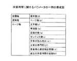
図4は所要時間に関するパラメータの一例の構成図である。図4の所要時間に関するパラメータは、会議毎の資料数と、資料毎のページ数と、ページ毎の文字数、単語数、図面の数、センテンス数、文章の読み易さ、文章の専門性、発表者の速度指定、過去の所要時間の記録と、を項目として有する。図4の所要時間に関するパラメータは、所要時間測定部40がページ、会議資料、会議等の予定所要時間を計算するために利用する。 FIG. 4 is a configuration diagram of an example of a parameter related to the required time. The parameters related to the time required in FIG. 4 are the number of materials per meeting, the number of pages per material, the number of characters per page, the number of words, the number of drawings, the number of sentences, the readability of sentences, the specialization of sentences, and the presentation. The user's speed designation and past required time record are included as items. The parameters related to the required time in FIG. 4 are used by the required
図5はページ毎の複雑度と、予定所要時間の多少との関係を表した一例のイメージ図である。図5の左側のページ1001は複雑度が大きいページのイメージ図である。図5の右側のページ1002は複雑度が小さいページのイメージ図である。本実施の形態に係る電子会議システム1は複雑度が大きいほど予定所要時間が多くなることを前提とするものである。左側のページ1001は文字数、図面の数などが右側のページ1002より大きくなっている。したがって、左側のページ1001は右側のページ1002より予定所要時間が多くなる。 FIG. 5 is an image diagram showing an example of the relationship between the complexity of each page and the estimated required time. A
なお、会議の閲覧者が操作する端末装置11は会議の発表者が操作する端末装置10と同様なソフトウェア構成であってもよい。この場合、会議の閲覧者が操作する端末装置11は会議部90の発表権管理部91より閲覧者が操作していることを判別できる。端末装置11は発表者が操作する端末装置10に表示される後述の進捗や警告の表示を行わないようにすればよい。 Note that the terminal device 11 operated by the conference viewer may have the same software configuration as the
また、表示部70は発表者が操作する端末装置10に表示される後述の進捗や警告の表示を、閲覧者が操作する端末装置11に表示してもよい。この場合、後述の進捗や警告の表示は発表者と閲覧者とで共有される。 Further, the
会議の閲覧者が操作する端末装置11は会議資料を表示する機能、端末装置10から共有情報を受信し、ページめくりなどの会議の発表者によるアクションを表示している会議資料に反映させる機能を有する構成であればよい。 The terminal device 11 operated by the conference viewer has a function of displaying conference material, a function of receiving shared information from the
<処理の詳細>
以下では、本実施形態に係る電子会議システム1の処理の詳細について説明する。<Details of processing>
Below, the detail of the process of the
《予定所要時間を算出するまでの処理》
図6は予定所要時間を算出するまでの処理を表した一例のフローチャートである。コンテンツ読み取り部20はステップS1において、会議に使用する会議資料を会議毎に読み込む。ステップS2に進み、コンテンツ読み取り部20は読み込んだ会議資料をページ毎に分割する。<< Processing until the estimated required time is calculated >>
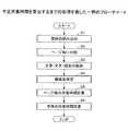
FIG. 6 is a flowchart illustrating an example of a process until the scheduled required time is calculated. In step S1, the
ステップS3に進み、コンテンツ読み取り部20は分割したページ毎に文章、文字及び図面を抽出する。ステップS4に進み、複雑度測定部30はコンテンツ読み取り部20が抽出したページ毎の文章、文字及び図面から複雑度を測定し、図7に示す所要時間に関するパラメータを作成する。図7は所要時間に関するパラメータの一例の構成図である。図7は図4の所要時間に関するパラメータと同一の項目であるため、説明を省略する。 In step S3, the
ステップS5に進み、所要時間測定部40は図7の所要時間に関するパラメータから会議資料のページ毎の予定所要時間を計算する。例えば所要時間測定部40は図7の所要時間に関するパラメータのうち、発表資料の各ページから取れるパラメータを式(1)のように使用し、定量的に予定所要時間を計算できる。 In step S5, the required
Tp=(c×tc+g×tg)×α…(1)
なお、Tpはページの所要予定時間とする。cはページの文字数とする。tcは1文字あたりの所要予定時間とする。gはページの図面の数とする。tgは1図面あたりの所要予定時間とする。αは文章の読み易さとする。Tp = (c × tc + g × tg) × α (1)
Tp is the required time for the page. Let c be the number of characters on the page. tc is the required time per character. Let g be the number of drawings on the page. tg is the required time per drawing. α is the readability of the text.
また、所要時間測定部40は図7の所要時間に関するパラメータのうち、発表者の速度指定係数(γ)と過去の所要時間の記録(tr)と式(2)のように使用し、定量的に予定所要時間を計算できる。 The required
Tp=tr×γ…(2)
ステップS6に進み、所要時間測定部40はページ毎の予定所要時間を式(3)のように積算して会議資料毎の予定所要時間を算出する。また、所要時間測定部40は会議資料毎の予定所要時間を式(4)のように積算して全体の所要予定時間を算出する。予想終了時刻は会議の開始時刻+全体の所要予定時間となる。Tp = tr × γ (2)
Proceeding to step S6, the required

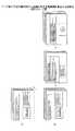
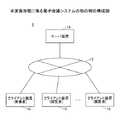
ステップS6のページ毎の予定所要時間を積算して会議資料毎の予定所要時間を算出する処理は図8(A)にイメージで示すような処理となる。また、ステップS6の会議資料毎の予定所要時間を積算して全体の所要予定時間を算出する処理は図8(B)にイメージで示すような処理となる。図8はページ毎の予定所要時間から会議の予定所要時間を算出する処理の一例のイメージ図である。 The process of calculating the scheduled required time for each conference material by integrating the scheduled required time for each page in step S6 is the process as shown in the image in FIG. Further, the process of calculating the total required scheduled time by adding the scheduled required time for each conference material in step S6 is a process as shown in the image of FIG. 8B. FIG. 8 is an image diagram of an example of a process for calculating the scheduled required time of the meeting from the scheduled required time for each page.
図8(A)に示すように、会議資料毎の予定所要時間はページ毎の予定所要時間の総和となる。また、図8(B)に示すように、会議の予定所要時間は会議資料毎の予定所要時間の総和となる。 As shown in FIG. 8A, the scheduled required time for each conference material is the sum of the scheduled required times for each page. Further, as shown in FIG. 8B, the scheduled required time of the conference is the sum of the required required times for each conference material.
《進捗を表示するまでの処理》
図9は進捗を表示するまでの処理を表した一例のフローチャートである。例えば図9のフローチャートの処理はページめくりのタイミングで行われる。<Processing until progress is displayed>
FIG. 9 is a flowchart illustrating an example of processing until the progress is displayed. For example, the process of the flowchart of FIG. 9 is performed at the page turning timing.
進捗管理部50はステップS11において、現在の時刻と、そのページの予定終了時刻とを比較する。ステップS12において、進捗管理部50は現在の時刻が、そのページの予定終了時刻から閾値以上遅れていればステップS13に進み、表示部70の進捗の表示を遅延に変更して警告する。 In step S11, the
ステップS12において、進捗管理部50は現在の時刻が、そのページの予定終了時刻から閾値以上遅れていなければステップS14に進む。進捗管理部50は現在の時刻が、ページの予定終了時刻より閾値以上早ければステップS15に進み、表示部70の進捗の表示を早いに変更して警告する。なお、ステップS14において、進捗管理部50は現在の時刻が、ページの予定終了時刻より閾値以上早くなければ、表示部70の進捗の表示を遅延にも早いにも変更せずに、図9のフローチャートの処理を終了する。 In step S12, the
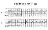
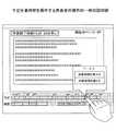
例えば進捗の警告表示は図10に示すようなものが考えられる。図10は進捗の警告表示の一例のイメージ図である。図10は上段に各ページの予定終了時刻が棒グラフにより表され、下段に各ページがページめくりされた時刻(各ページの実際の終了時刻)が棒グラフにより表されている。 For example, the progress warning display may be as shown in FIG. FIG. 10 is an image diagram of an example of a progress warning display. In FIG. 10, the scheduled end time of each page is represented by a bar graph in the upper row, and the time when each page was turned (actual end time of each page) is represented by a bar graph in the lower row.
図10(A)は現在の時刻が、ページの予定終了時刻から閾値以上遅れているときの進捗の警告表示の一例である。図10(A)の進捗の警告表示は3ページが遅延である(予定より遅い)ことを赤の着色や、予定終了時刻と実際の終了時刻との差を表す矢印などで表現している。 FIG. 10A is an example of a progress warning display when the current time is delayed by a threshold or more from the scheduled end time of the page. In the progress warning display of FIG. 10A, the fact that
また、図10(B)は現在の時刻が、ページの予定終了時刻より閾値以上早いときの進捗の警告表示の一例である。図10(B)の進捗の警告表示は4ページが早い(予定より早い)ことを青の着色や、予定終了時刻と実際の終了時刻との差を表す矢印などで表現している。 FIG. 10B is an example of a progress warning display when the current time is earlier than the threshold by a threshold value than the scheduled end time of the page. In the progress warning display in FIG. 10B, the fact that
進捗の警告表示は図11に示すようなものも考えられる。図11は進捗の警告表示の他の例のイメージ図である。図11は上段に各ページの予定終了時刻が棒グラフにより表され、中段に各ページがページめくりされた時刻(各ページの実際の終了時刻)が棒グラフにより表され、下段に最後にページめくりされた時刻(最後にページめくりされるまでの会議の所要時間)が棒グラフにより表されている。 A progress warning display as shown in FIG. 11 is also conceivable. FIG. 11 is an image diagram of another example of the progress warning display. In FIG. 11, the scheduled end time of each page is represented by a bar graph in the upper row, the time when each page is turned (in the middle row) (actual end time of each page) is represented by a bar graph, and the page is turned last in the lower row. The time (the time required for the meeting until the last page is turned) is represented by a bar graph.
図11はページ毎に進捗の警告表示を行うと共に、ページめくりされたページまでの会議の予定所要時間と実際の会議の所要時間との進捗の警告表示を行っている。例えば図11は4ページ目の所要時間(4ページが表示されていた時間)が4ページ目の予定所要時間と比較して閾値以上に早いことを中段の4ページに相当する箇所に例えば青の着色などで示す。 FIG. 11 displays a progress warning for each page and also displays a progress warning between the scheduled required time of the meeting up to the page turned and the actual required time of the meeting. For example, FIG. 11 shows that the time required for the fourth page (time during which
また、図11はページめくりされた5ページまでの会議の予定所要時間より、5ページをページめくりした実際の会議の所要時間が短いことを、下段に青で着色した棒グラフなどで示す。さらに、図11はページめくりされた5ページまでの会議の予定所要時間より実際の会議の所要時間が、どの程度ずれているのか(何分ずれているのか)をテキストでも示している。 Further, FIG. 11 shows, by a bar graph colored in blue in the lower row, that the time required for an actual meeting in which five pages are turned is shorter than the scheduled time required for a meeting up to five pages. Furthermore, FIG. 11 also shows in text the extent to which the actual meeting time is shifted from the scheduled time required for the meeting up to page 5 (how much it is shifted).
図12はページ毎に進捗を表示する処理を表した一例のフローチャートである。図12のフローチャートの処理は例えばページめくりのタイミングで行われる。なお、図12のフローチャートの処理は所定時間間隔で行ってもよい。 FIG. 12 is a flowchart illustrating an example of processing for displaying progress for each page. The process of the flowchart of FIG. 12 is performed, for example, at the page turning timing. Note that the processing of the flowchart of FIG. 12 may be performed at predetermined time intervals.
進捗管理部50はステップS21において、現在のページの所要時間(ページめくりされたページが表示されていた時間)を取得する。ステップS22において、進捗管理部50は現在のページの所要時間が、そのページの予定所要時間と閾値以上の差があるかを判定する。 In step S21, the
閾値以上の差があれば、進捗管理部50はステップS23において、現在のページの所要時間が、そのページの予定所要時間と比較して遅すぎるか(短すぎるか)判定する。そのページの予定所要時間と比較して遅すぎれば、進捗管理部50はステップS24において予定より遅いと警告を表示する。また、そのページの予定所要時間と比較して早すぎれば、進捗管理部50はステップS25において予定より早いと警告を表示する。 If there is a difference greater than or equal to the threshold, the
ステップS22において、現在のページの所要時間が、そのページの予定所要時間と閾値以上の差が無ければ、進捗管理部50は警告を表示せず、図12のフローチャートの処理を終了する。なお、図12のフローチャートの処理は、ページが戻ったときなど、所要時間が積算される度にページごとに行われる。 In step S22, if the required time of the current page is not different from the scheduled required time of the page by a threshold value or more, the
例えばページ毎の進捗の警告表示は、図13に示すようなものが考えられる。図13はページ毎の進捗の警告表示の一例のイメージ図である。図13は上段に各ページの予定所要時刻が棒グラフにより表され、下段に各ページの所要時間(実際に各ページが表示されていた時間)が棒グラフにより表されている。 For example, the progress warning display for each page may be as shown in FIG. FIG. 13 is an image diagram showing an example of a progress warning display for each page. In FIG. 13, the scheduled required time of each page is represented by a bar graph in the upper row, and the required time of each page (the time during which each page was actually displayed) is represented by a bar graph in the lower row.
図13(A)は3ページの所要時間が3ページの予定所要時間より閾値以上遅れているときの進捗の警告表示の一例である。図13(A)の進捗の警告表示は3ページが遅延であることを、棒グラフの3ページを表す領域を赤に着色することなどで表現する。 FIG. 13A is an example of a progress warning display when the required time for
図13(B)は4ページの所要時間が4ページの予定所要時間より閾値以上早いときの進捗の警告表示の一例である。図13(B)の進捗の警告表示は4ページが早いことを棒グラフの4ページを表す領域を青に着色することなどで表現する。 FIG. 13B is an example of a progress warning display when the required time for
《ページ毎の予定所要時間の更新》
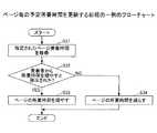
図14はページ毎の予定所要時間を更新する処理の一例のフローチャートである。進捗管理部50は発表者によりページ毎の予定所要時間を変更する指示がされると、ステップS31において、発表者により指定されたページの予定所要時間を取得する。《Update the estimated time required for each page》
FIG. 14 is a flowchart of an example of a process for updating the scheduled required time for each page. When the presenter gives an instruction to change the scheduled required time for each page, the
ステップS32において、進捗管理部50は発表者から予定所要時間を増やすと指示されたか判定する。発表者から予定所要時間を増やすと指示された場合、進捗管理部50はステップS33に進み、発表者が指定したページの予定所要時間を増やす。発表者から予定所要時間を減らすと指示された場合、進捗管理部50はステップS34に進み、発表者が指定したページの予定所要時間を減らす。 In step S32, the
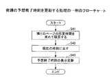
発表者によりページ毎の予定所要時間が更新されると、進捗管理部50は図15に示すフローチャートの処理を行い、会議の予想終了時刻も更新する。図15は会議の予想終了時刻を更新する処理の一例のフローチャートである。 When the scheduled required time for each page is updated by the presenter, the
ステップS41において、進捗管理部50は残りのページの予定所要時間を積算して会議が終了するまでの予定所要時間を算出する。ステップS42において、進捗管理部50は会議が終了するまでの予定所要時間を現在の時刻に足すことで、会議の予想終了時刻を算出する。ステップS43において、進捗管理部50は表示部70が表示している会議の予想終了時刻を、ステップS42で算出した会議の予想終了時刻により更新する。 In step S <b> 41, the
なお、図15のフローチャートの処理は、発表者によりページ毎の予定所要時間が更新された場合の他、ページめくりを行った場合もしくは所定時間間隔で行ってもよい。 Note that the processing of the flowchart of FIG. 15 may be performed when the page turn is performed or at predetermined time intervals, in addition to the case where the scheduled required time for each page is updated by the presenter.
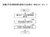
発表者によりページ毎もしくは全体の予定所要時間が更新されると、進捗管理部50は図16に示すフローチャートの処理を行い、会議の予定所要時間も更新する。図16は会議の予定所要時間を更新する処理の一例のフローチャートである。 When the presenter updates the total required time for each page or by the presenter, the
ステップS51において、進捗管理部50は残りのページの予定所要時間を積算して会議が終了するまでの予定所要時間を算出する。ステップS52において、進捗管理部50は表示部70の予定の表示を更新する。予定の表示とは、例えば各ページの予定所要時間の表示(前述した棒グラフなど)である。 In step S51, the
そして、ステップS53において、進捗管理部50は会議が終了するまでの予定所要時間を会議の開始時刻に足すことで、会議の予定終了時刻を算出し、表示部70の予定終了時刻の表示を更新する。 In step S53, the
例えば図15及び図16のフローチャートの処理により、ページ毎の進捗の警告表示は図17に示すように更新される。図17はページ毎の進捗の警告表示の更新を表した一例のイメージ図である。図17は図13と同様、上段に各ページの予定所要時刻が棒グラフにより表され、下段に各ページの所要時間(実際に各ページが表示されていた時間)が棒グラフにより表されている。 For example, the progress warning display for each page is updated as shown in FIG. 17 by the processing of the flowcharts of FIGS. FIG. 17 is an image diagram showing an example of updating the progress warning display for each page. In FIG. 17, as in FIG. 13, the scheduled required time of each page is represented by a bar graph in the upper row, and the required time of each page (the time during which each page was actually displayed) is represented by a bar graph in the lower row.
図17(A)は更新前の進捗の警告表示を表している。図17(B)は図17(A)の9ページ目の予定所要時間を増やした更新後の進捗の警告表示を表している。9ページ目の予定所要時間を増やしたことにより、図17(B)の進捗の警告表示は上段の予定終了時刻と下段の予想終了時刻とが遅くなっている。 FIG. 17A shows a warning display of progress before update. FIG. 17B shows a warning display of the progress after the update in which the estimated required time on the ninth page of FIG. 17A is increased. By increasing the scheduled required time on the ninth page, the progress warning display in FIG. 17B is delayed between the upper scheduled end time and the lower expected end time.
《画面例》
例えば発表者は簡単な操作で進捗の警告表示の表示/非表示を切り替えたり、表示する項目を変更したりできる。図18は会議中に発表者の端末装置に表示される画面の一例のイメージ図である。<Screen example>
For example, the presenter can switch display / non-display of the progress warning display with a simple operation, and change the displayed items. FIG. 18 is an image diagram of an example of a screen displayed on the presenter's terminal device during the conference.
図18の画面1100は上部の領域1101に会議の予想終了時刻及び予想遅延時間を表示すると共に、下部の領域1102にページ毎の予定と実際の所要時間の差を例えば色付けて表示する。発表者は例えば下部の領域1102を参照することで、予定より実際の所要時間が短すぎた(説明不足の可能性がある)ページを簡単に確認できるので、後で説明を追加するなどの対処ができる。 The
図19は会議中に発表者の端末装置に表示される画面の他の例のイメージ図である。図19の画面1200は上部の領域1201に会議の予想終了時刻を表示すると共に、下部の領域1202にページ毎の予定所要時間と実際の所要時間とを表示する。発表者は例えば下部の領域1202を参照することで、予定所要時間と実際の所要時間とを見比べることができる。 FIG. 19 is an image diagram of another example of a screen displayed on the presenter's terminal device during the conference. The screen 1200 of FIG. 19 displays the expected end time of the conference in the
図19(A)は4ページの実際の所要時間が予定所要時間よりも短すぎる例を表したものである。そのため、図19(A)は下部の領域1202に、予定より実際の所要時間が短すぎた(説明不足の可能性がある)ページが有る旨の警告を行っている。なお、下部の領域1202には会議の予定終了時刻との差異(20分早い)も表示されている。 FIG. 19A shows an example in which the actual required time for four pages is too shorter than the expected required time. For this reason, FIG. 19A warns that there is a page in the lower area 1202 where the actual required time is shorter than planned (possibly lacking explanation). In the lower area 1202, a difference (20 minutes earlier) from the scheduled end time of the conference is also displayed.
図19(B)は4ページの実際の所要時間が予定所要時間よりも長すぎる例を表したものである。そのため、図19(B)の下部の領域1202には会議の予定終了時刻との差異(5分遅い)が表示されている。 FIG. 19B shows an example in which the actual required time for four pages is too longer than the expected required time. Therefore, the difference (5 minutes later) from the scheduled end time of the conference is displayed in the lower area 1202 of FIG.
また、端末装置10は会議後、発表者からの指示により例えば図20に示す画面1300を表示する。図20は会議後に発表者の端末装置に表示される画面の一例のイメージ図である。図20の画面1300はページ毎の予定所要時間と実際の所要時間との差を表示するものである。例えば画面1300は色づけにより予定所要時間と実際の所要時間との差が少ないページ、予定所要時間より実際の所要時間が長すぎるページ、予定所要時間より実際の所要時間が短すぎるページ、を区別する。発表者は、画面1300を見ることにより、会議のテンポや各ページのボリュームの偏りなどを確認することができ、次回の発表の参考にすることができる。 Further, after the conference, the
なお、発表者は端末装置10に対するジェスチャーやボタン操作などで、例えば図20の画面1300に切り替えたり、別の情報表示をしたり、予定所要時間の操作をしたりもできる。 The presenter can switch to the
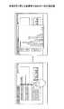
図21は画面を切り替える発表者の操作の一例の説明図である。図21の左側の画面において発表者は端末装置10のタッチパネルを上から下に線を引くようにタッチすることで右側の画面のように図20の画面1300を表示させることができる。 FIG. 21 is an explanatory diagram showing an example of the presenter's operation for switching the screen. In the screen on the left side of FIG. 21, the presenter can display the
図22は警告表示を確認する発表者の操作の一例の説明図である。図22の左側の画面において発表者は警告表示されているページの領域を端末装置10のタッチパネルによりタッチすることで右側の画面のように警告の内容を表示させることができる。 FIG. 22 is an explanatory diagram illustrating an example of an operation of the presenter confirming the warning display. In the screen on the left side of FIG. 22, the presenter can display the content of the warning as in the screen on the right side by touching the area of the page where the warning is displayed with the touch panel of the
図23は予定所要時間を操作する発表者の操作の一例の説明図である。会議中もしくは会議前にページの予定所要時間を変更したい場合、発表者は図23の画面において予定所要時間を操作したいページの領域を端末装置10のタッチパネルによりタッチすることで予定所要時間を増減させるボタンを表示させることができる。なお、予定所要時間を増減させるボタンが押下された場合、端末装置10は前述した図14のフローチャートの処理を実行する。 FIG. 23 is an explanatory diagram of an example of the operation of the presenter who operates the scheduled required time. When it is desired to change the scheduled required time of the page during or before the conference, the presenter increases or decreases the planned required time by touching the area of the page on which the required required time is to be operated on the screen of FIG. A button can be displayed. Note that when the button for increasing or decreasing the estimated required time is pressed, the
図24は全体の予定所要時間を操作する発表者の操作の一例の説明図である。会議中に全体の予定所要時間を変更したい場合、発表者は図24の画面において進捗の警告表示の領域を端末装置10のタッチパネルによりタッチすることで全体の予定所要時間を増減させる(ペースを変更する)ボタンを表示させることができる。 FIG. 24 is an explanatory diagram of an example of the presenter's operation for manipulating the entire estimated required time. If the presenter wants to change the total scheduled time during the meeting, the presenter increases or decreases the total required time by touching the progress warning display area on the touch panel of the
なお、ペースを変更するボタンが押下された場合、端末装置10は残りのページの予定所要時間を前述した図14のフローチャートにより更新する。さらに、端末装置10は図15及び図16のフローチャートの処理により予定所要時間及び予想終了時刻を更新したあと図24の画面を再表示する。 When the button for changing the pace is pressed, the
<まとめ>
本実施形態に係る電子会議システム1は予定所要時間と実際の所要時間との差を視覚的に表示することにより、会議の進捗を発表者に分かり易く示すことができる。また、本実施形態に係る電子会議システム1は予定所要時間と実際の所要時間との差から会議の終了時間を予想し、会議の予想終了時刻を発表者に示すことができる。<Summary>
The
したがって、本実施形態に係る電子会議システム1によれば、発表者が会議資料を表示しながら説明を行うとき、会議資料の表示の進捗判断を支援できる。例えば発表者は本実施形態に係る電子会議システム1を使用することで、会議資料の各ページに対する説明の過不足や、会議の予定終了時刻と各ページの実際の所要時間に基づく予想終了時刻との差を容易に確認できるので、説明のペースを容易に制御できる。 Therefore, according to the
なお、前述の説明では発表者に分かり易く表示する例として色付けを示したが、色付けに限るものではなく、例えば網掛けやポップアップ、点滅など、様々な表示方法が考えられる。 In the above description, coloring is shown as an example for easy display to the presenter. However, the present invention is not limited to coloring, and various display methods such as shading, pop-up, and blinking are conceivable.
また、本実施形態に係る電子会議システム1は会議資料から所要時間を測定するためのパラメータ(所要時間に関するパラメータ)を取得し、所要時間に関するパラメータから会議の予定所要時間を計算できる。したがって、本実施形態に係る電子会議システム1は会議に使用する会議資料を指定すれば会議の予定所要時間が容易に算出できる。 In addition, the
なお、前述の説明では会議の予定所要時間を所要時間に関するパラメータから自動で計算する例を示したが、発表者が会議の予定所要時間を手動で設定してもよい。
[第2の実施形態]
第2の実施形態に係る電子会議システムはサーバ装置を利用するものである。第2の実施形態に係る電子会議システムは第1の実施形態に係る電子会議システムと一部を除いて同様であるため、適宜説明を省略する。In the above description, an example in which the required time for the meeting is automatically calculated from the parameters related to the required time has been described. However, the presenter may manually set the required time for the meeting.
[Second Embodiment]
The electronic conference system according to the second embodiment uses a server device. Since the electronic conference system according to the second embodiment is the same as the electronic conference system according to the first embodiment except for a part thereof, description thereof will be omitted as appropriate.
図25は本実施形態に係る電子会議システムの他の例の構成図である。図25の電子会議システム2は、サーバ装置13、発表者のクライアント装置14、1又は複数の閲覧者のクライアント装置15がインターネットやLANなどのネットワーク12に接続される構成を一例として示している。 FIG. 25 is a configuration diagram of another example of the electronic conference system according to the present embodiment. The
サーバ装置13は、複数のコンピュータシステム上で動作するソフトウェアやサービスであってもよいし、1つのコンピュータシステム上で動作するソフトウェアやサービスであってもよい。サーバ装置13は例えばクラウドサービスの形態をとることもできる。 The
クライアント装置14は会議の発表者が操作する情報処理端末である。クライアント装置15は会議の閲覧者(発表者以外の参加者)が操作する情報処理端末である。なお、クライアント装置14及び15は、デスクトップパソコンやノートパソコン、タブレットPC、スマートフォンなどの情報処理が可能な機器である。 The
図25の電子会議システム2は図1の端末装置10で実施していた処理をサーバ装置13とクライアント装置14とに分けるものである。例えば電子会議システム2は表示やUIの機能をクライアント装置14で実施し、その他の機能をサーバ装置13で実施することが考えられる。また、電子会議システム2は高負荷の機能をサーバ装置13で実施する構成としてもよい。なお、ハードウェア構成は図2と同様であり、説明を省略する。 The
図26はサーバ装置の一例の処理ブロック図である。図27はクライアント装置の一例の処理ブロック図である。図26のサーバ装置13は図3の端末装置10の処理ブロックから表示部70、UI部80を除き、資料管理部100を追加した構成である。図27のクライアント装置14は図3の端末装置10の処理ブロックの表示部70、UI部80を有する構成である。なお、サーバ装置13の資料管理部100はデータベース部101を有する。データベース部101は会議資料を管理する。 FIG. 26 is a processing block diagram of an example of a server device. FIG. 27 is a processing block diagram of an example of a client device. The
第2の実施形態に係る電子会議システム2は、図1の端末装置10で実施していた処理をサーバ装置13とクライアント装置14とに分けているが、処理自体、第1の実施形態に係る電子会議システム1と同様であるため、説明を省略する。 The
<まとめ>
本実施形態に係る電子会議システム2は図1の端末装置10で実施していた処理の一部をサーバ装置13などの他の装置で実施可能である。したがって、本実施形態に係る電子会議システム2は高負荷の処理をクライアント装置14に替えてサーバ装置13に行わせることや、クラウドサービスとしてユーザに提供することもできる。<Summary>
In the
なお、電子会議システム2の構成は一例であって、用途や目的に応じて様々なシステム構成が可能である。また、電子会議システム2の機能構成は一例であって、他の機能構成も可能である。例えばサーバ装置13の機能の一部をクライアント装置14に設けることも可能である。 The configuration of the
本発明は、具体的に開示された上記の実施形態に限定されるものではなく、特許請求の範囲から逸脱することなく、種々の変形や変更が可能である。なお、特許請求の範囲に記載した分割情報は会議資料のページに相当する。 The present invention is not limited to the specifically disclosed embodiments, and various modifications and changes can be made without departing from the scope of the claims. The division information described in the claims corresponds to a conference material page.
1、2 電子会議システム
10、11 端末装置
12 ネットワーク
13 サーバ装置
14、15 クライアント装置
20 コンテンツ読み取り部
21 ページ抽出部
22 文章抽出部
23 文字抽出部
24 図面抽出部
30 複雑度測定部
31 複雑度取得部
32 文章複雑度測定部
40 所要時間測定部
41 ページ毎の所要時間測定部
42 資料毎の所要時間測定部
43 全体の所要時間測定部
50 進捗管理部
51 ページ毎の進捗管理部
52 全体の進捗管理部
60 記録部
61 所要時間の履歴記録部
70 表示部
71 進捗表示部
72 表示切替部
80 UI部
81 UI管理部
90 会議部
91 発表権管理部
92 画面共有部
100 資料管理部
101 データベース部
500 コンピュータシステム
501 入力装置
502 表示装置
503 外部I/F
503a 記録媒体
504 RAM(Random Access Memory)
505 ROM(Read Only Memory)
506 CPU(Central Processing Unit)
507 通信I/F
508 HDD(Hard Disk Drive)
B バスDESCRIPTION OF
503a Recording medium 504 RAM (Random Access Memory)
505 ROM (Read Only Memory)
506 CPU (Central Processing Unit)
507 Communication I / F
508 HDD (Hard Disk Drive)
B bus
Claims (9)
Translated fromJapanese前記情報を分割したページごとに前記ページを表示する予定所要時間と、前記ページを実際に表示した所要時間とを比較し、前記使用者の操作により切り替えられる前記ページごとの表示の進捗判断を行う進捗管理手段と、
前記ページごとの表示の進捗判断に基づき、前記ページごとの表示の進捗を前記ページごとの予定所要時間を表示領域の分割により表す第1の棒グラフと、前記ページごとの所要時間を表示領域の分割により表す第2の棒グラフとを、対応付けて表示し、前記第2の棒グラフの表示領域の表示変更により、前記予定所要時間に対して前記所要時間が遅れているのか早いのかを警告表示する表示手段と
を有する情報処理システム。An information display system for displaying information by a user operation,
A scheduledtime to displaythe page for each page obtained by dividing the information, compares the timerequired and that actually display thepage, and displays the progress determination foreach ofthe pages to be switched by the operation of the user Progress management means,
Based on the progress judgment display foreach of thepages, the display progress ofeach of thepagesin the first bar graph by resolution of the display region scheduled time for each of the pages, the division of the display area required time for each of the page The second bar graph represented by is displayedinassociation with eachother, and a display for displayingwhether the required time is delayed or early with respect to the scheduled required time by changing the display area of the second bar graph And an information processing system.
請求項1記載の情報処理システム。The progress management unit, an information processing system according to claim1, wherein calculating the expected time for displaying the information from the sum of the scheduledtimefor each of the dividedpage from the information.
前記ページごとの複雑度から前記ページを表示する予定所要時間を測定する予定所要時間測定手段と
を有する請求項1記載の情報処理システム。Complexity measuring means for measuring the complexity ofeach pagedivided from the information;
The information processing system according to claim 1 having ascheduled time measuring means for measuring a scheduledtime to display thepage from the complexity ofeach of thepages.
請求項3記載の情報処理システム。Thescheduled time measuring means, an information processing system according to claim3, wherein measuring the scheduledtime to display thepage thepage from the record of the timerequired previously displayed.
請求項1乃至4何れか一項記載の情報処理システム。The display means, the color change of the display area of the second bar, the required time is lagging the do early to either a warning display claims 1 to4 any one described for the scheduled time Information processing system.
請求項1乃至5何れか一項記載の情報処理システム。When the progress management means receives an operation from the user to update the scheduledrequired time for displaying thepage divided from the information after the display of the information is started, the progressrequired for thepage before the displayis displayed. claims1 to 5 the information processing systemaccording to any one claim updating the time.
請求項1乃至6何れか一項記載の情報処理システム。The information processing system according to any one of claims 1 to 6.
前記情報を分割したページごとに前記ページを表示する予定所要時間と、前記ページを実際に表示した所要時間とを比較し、前記使用者の操作により切り替えられる前記ページごとの表示の進捗判断を行う進捗管理手段と、
前記ページごとの表示の進捗判断に基づき、前記ページごとの表示の進捗を前記ページごとの予定所要時間を表示領域の分割により表す第1の棒グラフと、前記ページごとの所要時間を表示領域の分割により表す第2の棒グラフとを、対応付けて表示し、前記第2の棒グラフの表示領域の表示変更により、前記予定所要時間に対して前記所要時間が遅れているのか早いのかを警告表示する表示手段と
を有する情報処理装置。An information processing apparatus that displays information by a user's operation,
A scheduledtime to displaythe page for each page obtained by dividing the information, compares the timerequired and that actually display thepage, and displays the progress determination foreach ofthe pages to be switched by the operation of the user Progress management means,
Based on the progress judgment display foreach of thepages, the display progress ofeach of thepagesin the first bar graph by resolution of the display region scheduled time for each of the pages, the division of the display area required time for each of the page The second bar graph represented by is displayedinassociation with eachother, and a display for displayingwhether the required time is delayed or early with respect to the scheduled required time by changing the display area of the second bar graph And an information processing apparatus.
前記情報を分割したページごとに前記ページを表示する予定所要時間と、前記ページを実際に表示した所要時間とを比較し、前記使用者の操作により切り替えられる前記ページごとの表示の進捗判断を行う進捗管理手段、
前記ページごとの表示の進捗判断に基づき、前記ページごとの表示の進捗を前記ページごとの予定所要時間を表示領域の分割により表す第1の棒グラフと、前記ページごとの所要時間を表示領域の分割により表す第2の棒グラフとを、対応付けて表示し、前記第2の棒グラフの表示領域の表示変更により、前記予定所要時間に対して前記所要時間が遅れているのか早いのかを警告表示する表示手段
として機能させるためのプログラム。An information processing device that displays information by user operation,
A scheduledtime to displaythe page for each page obtained by dividing the information, compares the timerequired and that actually display thepage, and displays the progress determination foreach ofthe pages to be switched by the operation of the user Progress management means,
Based on the progress judgment display foreach of thepages, the display progress ofeach of thepagesin the first bar graph by resolution of the display region scheduled time for each of the pages, the division of the display area required time for each of the page The second bar graph represented by is displayedinassociation with eachother, and a display for displayingwhether the required time is delayed or early with respect to the scheduled required time by changing the display area of the second bar graph Program to function as a means.
Priority Applications (3)
| Application Number | Priority Date | Filing Date | Title |
|---|---|---|---|
| JP2012273436AJP6111641B2 (en) | 2012-12-14 | 2012-12-14 | Information display system, information processing apparatus, and program |
| US14/091,443US9495650B2 (en) | 2012-12-14 | 2013-11-27 | Information display system, information processing device, and information display method |
| BR102013032373ABR102013032373A2 (en) | 2012-12-14 | 2013-12-16 | INFORMATION DISPLAY SYSTEM, INFORMATION PROCESSING DEVICE AND INFORMATION DISCLOSURE METHOD |
Applications Claiming Priority (1)
| Application Number | Priority Date | Filing Date | Title |
|---|---|---|---|
| JP2012273436AJP6111641B2 (en) | 2012-12-14 | 2012-12-14 | Information display system, information processing apparatus, and program |
Publications (2)
| Publication Number | Publication Date |
|---|---|
| JP2014119864A JP2014119864A (en) | 2014-06-30 |
| JP6111641B2true JP6111641B2 (en) | 2017-04-12 |
Family
ID=50932510
Family Applications (1)
| Application Number | Title | Priority Date | Filing Date |
|---|---|---|---|
| JP2012273436AExpired - Fee RelatedJP6111641B2 (en) | 2012-12-14 | 2012-12-14 | Information display system, information processing apparatus, and program |
Country Status (3)
| Country | Link |
|---|---|
| US (1) | US9495650B2 (en) |
| JP (1) | JP6111641B2 (en) |
| BR (1) | BR102013032373A2 (en) |
Families Citing this family (8)
| Publication number | Priority date | Publication date | Assignee | Title |
|---|---|---|---|---|
| JP6354453B2 (en) | 2014-08-26 | 2018-07-11 | 株式会社リコー | Terminal device, screen sharing method, program, and screen sharing system |
| JP6354456B2 (en)* | 2014-08-27 | 2018-07-11 | 京セラドキュメントソリューションズ株式会社 | Electronic device and display program |
| US10725639B1 (en)* | 2015-01-14 | 2020-07-28 | Pma Technoloiges, Llc | Project schedule display with graphical target overlay |
| US9794413B2 (en)* | 2015-05-28 | 2017-10-17 | Avaya Inc. | Facilitation of a conference call between static and rotating participants |
| US10614418B2 (en)* | 2016-02-02 | 2020-04-07 | Ricoh Company, Ltd. | Conference support system, conference support method, and recording medium |
| JP7087556B2 (en)* | 2018-03-29 | 2022-06-21 | 株式会社リコー | Shared support server, shared system, support method, and program |
| CN113761833B (en)* | 2021-08-16 | 2024-12-24 | 联想(北京)有限公司 | A method, device and equipment for displaying document content |
| JP7424675B1 (en) | 2022-12-09 | 2024-01-30 | Necプラットフォームズ株式会社 | Conference server, how the server works, and programs |
Family Cites Families (15)
| Publication number | Priority date | Publication date | Assignee | Title |
|---|---|---|---|---|
| JP3593904B2 (en)* | 1998-12-25 | 2004-11-24 | 富士通株式会社 | Presentation pace guide system |
| US6834371B1 (en)* | 2000-08-31 | 2004-12-21 | Interactive Video Technologies, Inc. | System and method for controlling synchronization of a time-based presentation and its associated assets |
| JP4639734B2 (en)* | 2004-09-30 | 2011-02-23 | 富士ゼロックス株式会社 | Slide content processing apparatus and program |
| JP2006119875A (en)* | 2004-10-21 | 2006-05-11 | Seiko Epson Corp | Presentation system, presentation program, presentation method, and projector |
| US8340130B2 (en)* | 2005-01-14 | 2012-12-25 | Citrix Systems, Inc. | Methods and systems for generating playback instructions for rendering of a recorded computer session |
| JP2007043493A (en) | 2005-08-03 | 2007-02-15 | Pioneer Electronic Corp | Conference supporting system for managing progress of proceeding, conference supporting method, and conference supporting program |
| JP2007140721A (en) | 2005-11-16 | 2007-06-07 | Hitachi Ltd | Document specialization acquisition program |
| US20070124681A1 (en)* | 2005-11-28 | 2007-05-31 | Microsoft Corporation | Presentation timer |
| JP5322047B2 (en) | 2007-06-27 | 2013-10-23 | 国立大学法人長岡技術科学大学 | Text readability evaluation system |
| JP2011253225A (en)* | 2010-05-31 | 2011-12-15 | Konica Minolta Business Technologies Inc | Presentation support system, presentation support method, and computer program |
| CA2803047A1 (en)* | 2010-07-05 | 2012-01-12 | Cognitive Media Innovations (Israel) Ltd. | System and method of serial visual content presentation |
| JP5659634B2 (en) | 2010-08-30 | 2015-01-28 | 株式会社リコー | Conference progress support device, conference progress support system, conference progress support method, program |
| JP5609441B2 (en) | 2010-08-31 | 2014-10-22 | 株式会社リコー | Conference progress support device, conference progress support system, conference progress support method, program |
| US20130024772A1 (en)* | 2011-07-22 | 2013-01-24 | International Business Machines Corporation | Computer-based display presentation time management system |
| US20140344702A1 (en)* | 2013-05-20 | 2014-11-20 | Microsoft Corporation | Adaptive timing support for presentations |
- 2012
- 2012-12-14JPJP2012273436Apatent/JP6111641B2/ennot_activeExpired - Fee Related
- 2013
- 2013-11-27USUS14/091,443patent/US9495650B2/ennot_activeExpired - Fee Related
- 2013-12-16BRBR102013032373Apatent/BR102013032373A2/ennot_activeApplication Discontinuation
Also Published As
| Publication number | Publication date |
|---|---|
| JP2014119864A (en) | 2014-06-30 |
| US20140173491A1 (en) | 2014-06-19 |
| US9495650B2 (en) | 2016-11-15 |
| BR102013032373A2 (en) | 2017-06-20 |
Similar Documents
| Publication | Publication Date | Title |
|---|---|---|
| JP6111641B2 (en) | Information display system, information processing apparatus, and program | |
| CN106776514B (en) | An annotation method and device | |
| US9569082B1 (en) | Interactive threshold setting for pie charts | |
| US20150046856A1 (en) | Interactive Charts For Collaborative Project Management | |
| US9035887B1 (en) | Interactive user interface | |
| MX2011000605A (en) | Pan and zoom control. | |
| KR101932718B1 (en) | Device and method for changing size of display window on screen | |
| TW201606664A (en) | Event visualization on calendar with timeline | |
| US20160154562A1 (en) | Manipulating visual representations of data | |
| US9513713B2 (en) | Fine control of media presentation progress | |
| JP2014519095A (en) | Document glance and navigation | |
| US9229679B2 (en) | Image distribution apparatus, display apparatus, and image distribution system | |
| RU2622084C2 (en) | Method and device of schedule management | |
| US10558413B2 (en) | Degree of interest evaluation device | |
| TWI610220B (en) | Apparatus and method for automatically controlling display screen density | |
| JP2013037391A5 (en) | ||
| WO2019033664A1 (en) | Information display control method and apparatus, and intelligent teaching device and storage medium | |
| CN103616947A (en) | Method and device for determining screen-on time of electronic device | |
| KR20120131911A (en) | Electronic book system, method, and recording medium for providing electronic book user interface | |
| JP2017033439A (en) | Display control apparatus and program | |
| KR20090016959A (en) | Scrap Execution Method on E-book Viewer Screen and Applied Apparatus | |
| JP2010072427A5 (en) | ||
| JP2015041204A (en) | Status display control device, status display control method, and program | |
| JPWO2014170973A1 (en) | Display control apparatus, information processing apparatus, display control method, display control program, and information processing system | |
| JP5816596B2 (en) | Display control apparatus and display control method thereof |
Legal Events
| Date | Code | Title | Description |
|---|---|---|---|
| A621 | Written request for application examination | Free format text:JAPANESE INTERMEDIATE CODE: A621 Effective date:20151112 | |
| A131 | Notification of reasons for refusal | Free format text:JAPANESE INTERMEDIATE CODE: A131 Effective date:20160830 | |
| A977 | Report on retrieval | Free format text:JAPANESE INTERMEDIATE CODE: A971007 Effective date:20160831 | |
| A521 | Request for written amendment filed | Free format text:JAPANESE INTERMEDIATE CODE: A523 Effective date:20161031 | |
| TRDD | Decision of grant or rejection written | ||
| A01 | Written decision to grant a patent or to grant a registration (utility model) | Free format text:JAPANESE INTERMEDIATE CODE: A01 Effective date:20170214 | |
| A61 | First payment of annual fees (during grant procedure) | Free format text:JAPANESE INTERMEDIATE CODE: A61 Effective date:20170227 | |
| R151 | Written notification of patent or utility model registration | Ref document number:6111641 Country of ref document:JP Free format text:JAPANESE INTERMEDIATE CODE: R151 | |
| LAPS | Cancellation because of no payment of annual fees |