JP6110848B2 - Gas processing method - Google Patents
Gas processing methodDownload PDFInfo
- Publication number
- JP6110848B2 JP6110848B2JP2014516713AJP2014516713AJP6110848B2JP 6110848 B2JP6110848 B2JP 6110848B2JP 2014516713 AJP2014516713 AJP 2014516713AJP 2014516713 AJP2014516713 AJP 2014516713AJP 6110848 B2JP6110848 B2JP 6110848B2
- Authority
- JP
- Japan
- Prior art keywords
- gas
- chamber
- pressure
- reaction
- etching
- Prior art date
- Legal status (The legal status is an assumption and is not a legal conclusion. Google has not performed a legal analysis and makes no representation as to the accuracy of the status listed.)
- Active
Links
- 238000003672processing methodMethods0.000titleclaimsdescription10
- 239000007789gasSubstances0.000claimsdescription178
- 238000005530etchingMethods0.000claimsdescription57
- 238000000034methodMethods0.000claimsdescription28
- 238000006243chemical reactionMethods0.000claimsdescription23
- VYPSYNLAJGMNEJ-UHFFFAOYSA-NSilicium dioxideChemical compoundO=[Si]=OVYPSYNLAJGMNEJ-UHFFFAOYSA-N0.000claimsdescription21
- 229910052814silicon oxideInorganic materials0.000claimsdescription21
- 238000010790dilutionMethods0.000claimsdescription16
- 239000012895dilutionSubstances0.000claimsdescription16
- 239000007795chemical reaction productSubstances0.000claimsdescription8
- 238000010438heat treatmentMethods0.000claimsdescription6
- 238000000354decomposition reactionMethods0.000claimsdescription5
- 238000002955isolationMethods0.000claimsdescription4
- 235000012431wafersNutrition0.000description47
- KRHYYFGTRYWZRS-UHFFFAOYSA-NFluoraneChemical compoundFKRHYYFGTRYWZRS-UHFFFAOYSA-N0.000description26
- 229910000040hydrogen fluorideInorganic materials0.000description24
- 229910004298SiO 2Inorganic materials0.000description6
- 238000010586diagramMethods0.000description6
- 239000004065semiconductorSubstances0.000description6
- QGZKDVFQNNGYKY-UHFFFAOYSA-NAmmoniaChemical compoundNQGZKDVFQNNGYKY-UHFFFAOYSA-N0.000description5
- 239000011261inert gasSubstances0.000description5
- -1ammonium fluorosilicateChemical compound0.000description4
- IJGRMHOSHXDMSA-UHFFFAOYSA-NAtomic nitrogenChemical compoundN#NIJGRMHOSHXDMSA-UHFFFAOYSA-N0.000description3
- 229910001873dinitrogenInorganic materials0.000description3
- XUIMIQQOPSSXEZ-UHFFFAOYSA-NSiliconChemical compound[Si]XUIMIQQOPSSXEZ-UHFFFAOYSA-N0.000description2
- 229910021529ammoniaInorganic materials0.000description2
- 230000007423decreaseEffects0.000description2
- 239000000463materialSubstances0.000description2
- 239000012495reaction gasSubstances0.000description2
- 229910052710siliconInorganic materials0.000description2
- 239000010703siliconSubstances0.000description2
- 239000000126substanceSubstances0.000description2
- 239000000758substrateSubstances0.000description2
- XLYOFNOQVPJJNP-UHFFFAOYSA-NwaterSubstancesOXLYOFNOQVPJJNP-UHFFFAOYSA-N0.000description2
- 229910018072Al 2 O 3Inorganic materials0.000description1
- BOTDANWDWHJENH-UHFFFAOYSA-NTetraethyl orthosilicateChemical compoundCCO[Si](OCC)(OCC)OCCBOTDANWDWHJENH-UHFFFAOYSA-N0.000description1
- 238000002048anodisation reactionMethods0.000description1
- 239000000969carrierSubstances0.000description1
- 238000007865dilutingMethods0.000description1
- 239000003085diluting agentSubstances0.000description1
- 238000001312dry etchingMethods0.000description1
- 238000004519manufacturing processMethods0.000description1
- 238000007789sealingMethods0.000description1
- 239000011343solid materialSubstances0.000description1
- 238000001179sorption measurementMethods0.000description1
- 230000008016vaporizationEffects0.000description1
- 238000001039wet etchingMethods0.000description1
Images


Classifications
- H—ELECTRICITY
- H01—ELECTRIC ELEMENTS
- H01L—SEMICONDUCTOR DEVICES NOT COVERED BY CLASS H10
- H01L21/00—Processes or apparatus adapted for the manufacture or treatment of semiconductor or solid state devices or of parts thereof
- H01L21/02—Manufacture or treatment of semiconductor devices or of parts thereof
- H01L21/04—Manufacture or treatment of semiconductor devices or of parts thereof the devices having potential barriers, e.g. a PN junction, depletion layer or carrier concentration layer
- H01L21/18—Manufacture or treatment of semiconductor devices or of parts thereof the devices having potential barriers, e.g. a PN junction, depletion layer or carrier concentration layer the devices having semiconductor bodies comprising elements of Group IV of the Periodic Table or AIIIBV compounds with or without impurities, e.g. doping materials
- H01L21/30—Treatment of semiconductor bodies using processes or apparatus not provided for in groups H01L21/20 - H01L21/26
- H01L21/302—Treatment of semiconductor bodies using processes or apparatus not provided for in groups H01L21/20 - H01L21/26 to change their surface-physical characteristics or shape, e.g. etching, polishing, cutting
- H01L21/306—Chemical or electrical treatment, e.g. electrolytic etching
- H01L21/3065—Plasma etching; Reactive-ion etching
- H—ELECTRICITY
- H01—ELECTRIC ELEMENTS
- H01L—SEMICONDUCTOR DEVICES NOT COVERED BY CLASS H10
- H01L21/00—Processes or apparatus adapted for the manufacture or treatment of semiconductor or solid state devices or of parts thereof
- H01L21/02—Manufacture or treatment of semiconductor devices or of parts thereof
- H01L21/04—Manufacture or treatment of semiconductor devices or of parts thereof the devices having potential barriers, e.g. a PN junction, depletion layer or carrier concentration layer
- H01L21/18—Manufacture or treatment of semiconductor devices or of parts thereof the devices having potential barriers, e.g. a PN junction, depletion layer or carrier concentration layer the devices having semiconductor bodies comprising elements of Group IV of the Periodic Table or AIIIBV compounds with or without impurities, e.g. doping materials
- H01L21/30—Treatment of semiconductor bodies using processes or apparatus not provided for in groups H01L21/20 - H01L21/26
- H01L21/31—Treatment of semiconductor bodies using processes or apparatus not provided for in groups H01L21/20 - H01L21/26 to form insulating layers thereon, e.g. for masking or by using photolithographic techniques; After treatment of these layers; Selection of materials for these layers
- H01L21/3105—After-treatment
- H01L21/311—Etching the insulating layers by chemical or physical means
- H01L21/31105—Etching inorganic layers
- H01L21/31111—Etching inorganic layers by chemical means
- H01L21/31116—Etching inorganic layers by chemical means by dry-etching
- H—ELECTRICITY
- H01—ELECTRIC ELEMENTS
- H01L—SEMICONDUCTOR DEVICES NOT COVERED BY CLASS H10
- H01L21/00—Processes or apparatus adapted for the manufacture or treatment of semiconductor or solid state devices or of parts thereof
- H01L21/67—Apparatus specially adapted for handling semiconductor or electric solid state devices during manufacture or treatment thereof; Apparatus specially adapted for handling wafers during manufacture or treatment of semiconductor or electric solid state devices or components ; Apparatus not specifically provided for elsewhere
- H01L21/67005—Apparatus not specifically provided for elsewhere
- H01L21/67011—Apparatus for manufacture or treatment
- H01L21/67017—Apparatus for fluid treatment
- H01L21/67063—Apparatus for fluid treatment for etching
- H01L21/67069—Apparatus for fluid treatment for etching for drying etching
- H—ELECTRICITY
- H01—ELECTRIC ELEMENTS
- H01L—SEMICONDUCTOR DEVICES NOT COVERED BY CLASS H10
- H01L21/00—Processes or apparatus adapted for the manufacture or treatment of semiconductor or solid state devices or of parts thereof
- H01L21/70—Manufacture or treatment of devices consisting of a plurality of solid state components formed in or on a common substrate or of parts thereof; Manufacture of integrated circuit devices or of parts thereof
- H01L21/71—Manufacture of specific parts of devices defined in group H01L21/70
- H01L21/76—Making of isolation regions between components
- H01L21/762—Dielectric regions, e.g. EPIC dielectric isolation, LOCOS; Trench refilling techniques, SOI technology, use of channel stoppers
- H01L21/76224—Dielectric regions, e.g. EPIC dielectric isolation, LOCOS; Trench refilling techniques, SOI technology, use of channel stoppers using trench refilling with dielectric materials
Landscapes
- Engineering & Computer Science (AREA)
- Physics & Mathematics (AREA)
- Microelectronics & Electronic Packaging (AREA)
- General Physics & Mathematics (AREA)
- Manufacturing & Machinery (AREA)
- Computer Hardware Design (AREA)
- Condensed Matter Physics & Semiconductors (AREA)
- Power Engineering (AREA)
- Chemical & Material Sciences (AREA)
- Chemical Kinetics & Catalysis (AREA)
- General Chemical & Material Sciences (AREA)
- Inorganic Chemistry (AREA)
- Plasma & Fusion (AREA)
- Drying Of Semiconductors (AREA)
Description
Translated fromJapanese本発明は、フッ化水素(HF)ガスとアンモニア(NH3)ガスの混合ガスを用いて化学的酸化物除去処理を行うガス処理方法に関する。The present invention relates to a gas processing method for performing chemical oxide removal processing using a mixed gas of hydrogen fluoride (HF) gas and ammonia (NH3 ) gas.
近時、半導体デバイスの製造過程で、ドライエッチングやウエットエッチングに代わる微細化エッチングが可能な方法として、化学的酸化物除去処理(Chemical Oxide Removal;COR)と呼ばれる手法が注目されている。 Recently, a method called chemical oxide removal (COR) has attracted attention as a method capable of performing fine etching instead of dry etching or wet etching in the manufacturing process of a semiconductor device.
CORとしては、真空に保持されたチャンバー内で、被処理体である半導体ウエハの表面に存在するシリコン酸化膜(SiO2膜)に、フッ化水素(HF)ガスとアンモニア(NH3)ガスを吸着させ、これらをシリコン酸化膜と反応させてフルオロケイ酸アンモニウム((NH4)2SiF6;AFS)を生成させ、次工程で加熱によりこのフルオロケイ酸アンモニウムを昇華させることにより、シリコン酸化膜をエッチングするプロセスが知られている(例えば、特許文献1、2参照)。As the COR, hydrogen fluoride (HF) gas and ammonia (NH3 ) gas are applied to a silicon oxide film (SiO2 film) existing on the surface of a semiconductor wafer as an object to be processed in a vacuum chamber. By adsorbing and reacting these with a silicon oxide film, ammonium fluorosilicate ((NH4 )2 SiF6 ; AFS) is generated, and in the next step, the ammonium fluorosilicate is sublimated by heating, whereby a silicon oxide film is obtained. A process for etching is known (for example, see Patent Documents 1 and 2).
上記のようにシリコン酸化膜をエッチングする場合、HFガスおよびNH3ガスの混合ガスとシリコン酸化膜とを反応させる際には、チャンバー内の圧力を10〜100mTorr(1.33〜13.3Pa)、半導体ウエハの温度を30〜40℃、全ガスの流量を100〜200sccm(mL/min)とする条件が採用されている。When the silicon oxide film is etched as described above, when the mixed gas of HF gas and NH3 gas reacts with the silicon oxide film, the pressure in the chamber is set to 10 to 100 mTorr (1.33 to 13.3 Pa). The conditions are such that the temperature of the semiconductor wafer is 30 to 40 ° C. and the flow rate of all gases is 100 to 200 sccm (mL / min).
ところで、ウエハ表面のパターン状のシリコン酸化膜をエッチングする場合、パターンの微細化とともにパターン底面でのエッチレートが減少し、パターン底面でシリコン酸化膜が残存してしまうという不都合が発生する。このようなエッチング残りが発生した場合には、通常処理の温度を上昇させてエッチングレートを上昇させるが、温度を上昇させた場合にはエッチング形状がテーパー状となってしまう。 By the way, when the patterned silicon oxide film on the wafer surface is etched, the etching rate at the bottom surface of the pattern decreases with the miniaturization of the pattern, and the silicon oxide film remains on the bottom surface of the pattern. When such etching residue occurs, the temperature of normal processing is raised to increase the etching rate, but when the temperature is raised, the etching shape becomes tapered.
したがって、本発明の目的は、HFガスおよびNH3ガスの混合ガスによりパターン状のシリコン酸化膜をエッチングする場合に、パターン底面でのエッチング残りが生じず、かつ垂直性の高いエッチングを行うことができるガス処理方法を提供することにある。Accordingly, an object of the present invention is to perform etching with high verticality without causing etching residue at the bottom of the pattern when etching a patterned silicon oxide film with a mixed gas of HF gas and NH3 gas. An object of the present invention is to provide a gas processing method that can be used.
本発明者は、パターン状のシリコン酸化膜が形成された被処理体を反応ガスであるHFガスおよびNH3ガスで処理し、反応ガスとシリコン酸化膜との反応により生成した反応生成物を加熱して分解除去してエッチングするにあたり、これら反応ガスに加える希釈ガスの量を調整してチャンバー内の圧力を高くすることにより、エッチング残りが存在せず、かつ垂直性の高いエッチング形状が得られることを見出した。The present inventor treats a target object on which a patterned silicon oxide film is formed with HF gas and NH3 gas, which are reaction gases, and heats a reaction product generated by the reaction between the reaction gas and the silicon oxide film. Then, when etching by removing by decomposition, the amount of dilution gas added to these reaction gases is adjusted to increase the pressure in the chamber, so that there is no etching residue and an etching shape with high perpendicularity can be obtained. I found out.
すなわち、本発明によれば、チャンバー内に表面にパターン状のシリコン酸化膜が形成された被処理体を収容し、前記チャンバー内に反応ガスであるHFガスおよびNH3ガス、ならびに希釈ガスを供給して、これらと前記シリコン酸化膜とを反応させる処理を行い、その後、この反応により生成した反応生成物を加熱して分解除去する処理を行って、前記シリコン酸化膜をエッチングするガス処理方法であって、前記反応させる処理の、前記チャンバー内の圧力、処理温度、ならびに前記HFガス、前記NH3ガス、および希釈ガスの流量の条件が、その後前記分解除去する処理を行ってエッチング残りが存在する所定条件である場合に、前記反応させる処理の条件を、前記処理温度、および前記HFガスおよび前記NH3ガスの流量を前記所定条件に維持したまま、前記希釈ガスの量を前記所定条件から増加させて、前記チャンバー内の圧力を上昇させた条件にして前記反応させる処理を行い、その後前記分解除去する処理を行うことにより、前記エッチング残りを解消するとともに、垂直性の高いエッチング形状となるようにする、ガス処理方法が提供される。That is, according to the present invention, an object to be processed having a patterned silicon oxide film formed on the surface is accommodated in the chamber, and HF gas and NH3 gas, which are reaction gases, and a dilution gas are supplied into the chamber. Then, a process of reacting these with the silicon oxide film is performed, and then a reaction product generated by this reaction is heated and decomposed and removedto etch thesilicon oxide film. The conditions of the pressure in the chamber, the processing temperature, and the flow rates of the HF gas, the NH3 gas, and the dilution gas of thereaction to be reactedare then processed by the decomposition and removal, and there remainsan etching residue. whena predetermined condition forthe condition of the process of the reaction, the treatment temperature, and the flow rate of the HF gas and the NH3 gas While maintainingthe serial predetermined condition, the amount of the diluent gas is increasedfrom the predeterminedcondition,a process of reactingbefore SLon condition that increases the pressure in the chamber,performing then the decomposition is removed processing Thus, there is provided a gas processing method that eliminates the etching residue and achieves a highly perpendicular etching shape.
本発明において、前記チャンバー内の圧力を上昇させた条件下での前記反応させる処理の処理温度を40℃以下、前記チャンバー内の圧力を200mTorr以上とすることが好ましい。前記チャンバー内の圧力を上昇させた条件下での前記反応させる処理の処理温度を35℃以下とすることがより好ましい。In the present invention, it is preferable that the treatment temperature for the reactionunder the condition that the pressure in the chamber is increased is 40 ° C. or less, and the pressure in the chamber is 200 mTorr or more. More preferably, the treatment temperature for the reactionunder the condition of increasing the pressure in the chamber is 35 ° C. or lower.
前記チャンバー内の圧力を上昇させた条件下での前記反応させる処理を行う際に、前記チャンバー内のHFガスの分圧が5〜50mTorr、NH3ガスの分圧が5〜50mTorr、希釈ガスの分圧が200mTorr以上となるように、前記HFガス、前記NH3ガス、および希釈ガスの流量を調整することが好ましい。When performing the reactionunder the condition of increasing the pressure in the chamber, the partial pressure of HF gas in the chamber is 5 to 50 mTorr, the partial pressure of NH3 gas is 5 to 50 mTorr, It is preferable to adjust the flow rates of the HF gas, the NH3 gas, and the dilution gas so that the partial pressure becomes 200 mTorr or more.
また、前記チャンバー内の圧力を上昇させた条件下での前記反応させる処理を行う際に、前記チャンバー内の圧力を300mTorr以上とすることが好ましい。Further, when performing the reaction treatmentunder the condition in which the pressure in the chamber is increased , the pressure in the chamber is preferably set to 300 mTorr or more.
さらに、本発明のガス処理は、シャロートレンチアイソレーション構造のパターン状の熱酸化膜のエッチングに適用することができる。 Furthermore, the gas treatment of the present invention can be applied to etching of a patterned thermal oxide film having a shallow trench isolation structure.
以下、図面を参照しながら、本発明の実施の形態について説明する。
図1は、本発明の一実施形態に係るガス処理方法を実施するための処理システムを示す概略構成図である。この処理システム1は、半導体ウエハ(以下、単にウエハと記す)Wを搬入出する搬入出部2と、搬入出部2に隣接させて設けられた2つのロードロック室(L/L)3と、各ロードロック室3にそれぞれ隣接して設けられた、ウエハWに対してPHT(Post Heat Treatment)処理を行なうPHT処理装置(PHT)4と、各PHT処理装置4にそれぞれ隣接して設けられた、ウエハWに対してCOR処理を行なうCOR処理装置(COR)5とを備えている。ロードロック室3、PHT処理装置4およびCOR処理装置5は、この順に一直線上に並べて設けられている。Hereinafter, embodiments of the present invention will be described with reference to the drawings.
FIG. 1 is a schematic configuration diagram showing a processing system for carrying out a gas processing method according to an embodiment of the present invention. The processing system 1 includes a loading /
搬入出部2は、ウエハWを搬送する第1ウエハ搬送機構11が内部に設けられた搬送室(L/M)12を有している。第1ウエハ搬送機構11は、ウエハWを略水平に保持する2つの搬送アーム11a,11bを有している。搬送室12の長手方向の側部には、載置台13が設けられており、この載置台13には、ウエハWを複数枚並べて収容可能なキャリアCが例えば3つ接続できるようになっている。また、搬送室12に隣接して、ウエハWを回転させて偏心量を光学的に求めて位置合わせを行なうオリエンタ14が設置されている。 The loading /
搬入出部2において、ウエハWは、搬送アーム11a,11bによって保持され、第1ウエハ搬送機構11の駆動により略水平面内で直進移動、または昇降させられることにより、所望の位置に搬送させられる。そして、載置台13上のキャリアC、オリエンタ14、ロードロック室3に対してそれぞれ搬送アーム11a,11bが進退することにより、搬入出させられるようになっている。 In the loading /
各ロードロック室3は、搬送室12との間にそれぞれゲートバルブ16が介在された状態で、搬送室12にそれぞれ連結されている。各ロードロック室3内には、ウエハWを搬送する第2ウエハ搬送機構17が設けられている。また、ロードロック室3は、所定の真空度まで真空引き可能に構成されている。 Each
第2ウエハ搬送機構17は、多関節アーム構造を有しており、ウエハWを略水平に保持するピックを有している。この第2ウエハ搬送機構17においては、多関節アームを縮めた状態でピックがロードロック室3内に位置し、多関節アームを伸ばすことにより、ピックがPHT処理装置4に到達し、さらに伸ばすことによりCOR処理装置5に到達することが可能となっており、ウエハWをロードロック室3、PHT処理装置4、およびCOR処理装置5間で搬送することが可能となっている。 The second
PHT処理装置4は、図2に示すように、真空引き可能なチャンバー20と、その中でウエハWを載置する載置台23を有し、載置台23にはヒーター24が埋設されており、このヒーター24によりCOR処理が施された後のウエハWを加熱してCOR処理により生成した反応生成物を気化(昇華)させるPHT処理を行なう。チャンバー20のロードロック室3側には、ロードロック室3との間でウエハを搬送する搬入出口20aが設けられており、この搬入出口20aはゲートバルブ22によって開閉可能となっている。また、チャンバー20のCOR処理装置5側にはCOR処理装置5との間でウエハWを搬送する搬入出口20bが設けられており、この搬入出口20bはゲートバルブ54により開閉可能となっている。さらに、チャンバー20に例えば窒素ガス(N2)などの不活性ガスを供給するガス供給路25を備えたガス供給機構26、およびチャンバー20内を排気する排気路27を備えた排気機構28が備えられている。ガス供給路25は、窒素ガス供給源30に接続されている。そして、ガス供給路25には、流路の開閉動作および窒素ガスの供給流量の調節が可能な流量調整弁31が介設されている。排気機構28の排気路27には、開閉弁32および真空ポンプ33が設けられている。As shown in FIG. 2, the
COR処理装置5は、図3に示すように、密閉構造のチャンバー40を備えており、チャンバー40の内部には、ウエハWを略水平にした状態で載置させる載置台42が設けられている。また、COR処理装置5には、チャンバー40にHFガスおよびNH3ガス等を供給するガス供給機構43、チャンバー40内を排気する排気機構44が設けられている。As shown in FIG. 3, the
チャンバー40は、チャンバー本体51と蓋部52とによって構成されている。チャンバー本体51は、略円筒形状の側壁部51aと底部51bとを有し、上部は開口となっており、この開口が蓋部52で閉止される。側壁部51aと蓋部52とは、シール部材(図示せず)により封止されて、チャンバー40内の気密性が確保される。 The
側壁部51aには、PHT処理装置4のチャンバー20に対してウエハWを搬入出する搬入出口53が設けられており、この搬入出口53はゲートバルブ54により開閉可能となっている。 The
蓋部52は、外側を構成する蓋部材55と、蓋部材55の内側に嵌め込まれ、載置台42に臨むように設けられたシャワーヘッド56とを有している。シャワーヘッド56は円筒状をなす側壁57aと上部壁57bとを有する本体57と、本体57の底部に設けられたシャワープレート58とを有している。本体57とシャワープレート58とで形成される空間には、シャワープレート58と平行にプレート59が設けられており、本体57の上部壁57bとプレート59との間は第1の空間60aとなっており、プレート59とシャワープレート58との間は第2の空間60bとなっている。 The
第1の空間60aには、ガス供給機構43の第1のガス供給配管71が挿入されており、第1の空間60aに繋がる複数のガス通路61がプレート59からシャワープレート58に延びている。このガス通路61は、シャワープレート58に形成された複数の第1のガス吐出孔62に繋がっている。一方、第2の空間60bには、ガス供給機構の第2のガス供給配管72が挿入されており、この第2の空間60bには、シャワープレート58に形成された複数の第2のガス吐出孔63が繋がっている。 A first
そして、第1のガス供給配管71から第1の空間60aに供給されたガスがガス通路61および第1のガス吐出孔62を経てチャンバー40内へ吐出される。また、第2のガス供給配管72から第2の空間60bに供給されたガスが第2のガス吐出孔63から吐出される。 Then, the gas supplied from the first
載置台42は、平面視略円形をなしており、チャンバー40の底部51bに固定されている。載置台42の内部には、載置台42の温度を調節する温度調節器65が設けられている。温度調節器65は、例えば温度調節用媒体(例えば水など)が循環する管路を備えており、このような管路内を流れる温度調節用媒体と熱交換が行なわれることにより、載置台42の温度が調節され、載置台42上のウエハWの温度制御がなされる。 The mounting table 42 has a substantially circular shape in plan view, and is fixed to the bottom 51 b of the
ガス供給機構43は、上述した第1のガス供給配管71および第2のガス供給配管72を有しており、さらにこれら第1のガス供給配管71および第2のガス供給配管72にそれぞれ接続されたHFガス供給源73およびNH3ガス供給源74を有している。また、第1のガス供給配管71には第3のガス供給配管75が接続され、第2のガス供給配管72には第4のガス供給配管76が接続されていて、これら第3のガス供給配管75および第4のガス供給配管76には、それぞれArガス供給源77およびN2ガス供給源78が接続されている。第1〜第4のガス供給配管71、72、75、76には流路の開閉動作および流量制御を行う流量制御器79が設けられている。流量制御器79は例えば開閉弁およびマスフローコントローラにより構成されている。The
そして、HFガスおよびArガスは、第1のガス供給配管71、第1の空間60aおよびガス通路61を経て第1のガス吐出孔62からチャンバー40内へ吐出され、NH3ガスおよびN2ガスは、第2のガス供給配管72および第2の空間60bを経て第2のガス吐出孔63からチャンバー40内へ吐出される。Then, the HF gas and the Ar gas are discharged from the first
上記ガスのうちHFガスとNH3ガスは反応ガスであり、これらはシャワーヘッド56から吐出されるまで混合されることなく、チャンバー40内で初めて混合されるようになっている。ArガスおよびN2ガスは希釈ガスである。そして、チャンバー40内に、反応ガスであるHFガスおよびNH3ガスと、希釈ガスであるArガスおよびN2ガスとを所定流量で導入してチャンバー40内を所定圧力に維持しつつ、HFガスおよびNH3ガスとウエハW上に形成された酸化膜(SiO2)とを反応させ、反応生成物としてフルオロケイ酸アンモニウム(AFS)を生成させる。Among the above gases, HF gas and NH3 gas are reaction gases, and these are not mixed until they are discharged from the
希釈ガスとしては、Arガスのみ、またはN2ガスのみであってもよく、また、他の不活性ガスを用いても、Arガス、N2ガスおよび他の不活性ガスの2種以上を用いてもよい。As the diluting gas, only Ar gas or N2 gas may be used, and other inert gases may be used, or two or more of Ar gas, N2 gas and other inert gases may be used. May be.
排気機構44は、チャンバー40の底部51bに形成された排気口81に繋がる排気配管82を有しており、さらに、排気配管82に設けられた、チャンバー40内の圧力を制御するための自動圧力制御弁(APC)83およびチャンバー40内を排気するための真空ポンプ84を有している。 The
チャンバー40の側壁からチャンバー40内に、チャンバー40内の圧力を計測するための圧力計としての2つのキャパシタンスマノメータ86a,86bが設けられている。キャパシタンスマノメータ86aは高圧力用、キャパシタンスマノメータ86bは低圧力用となっている。 Two
COR処理装置5を構成するチャンバー40、載置台42等の各種構成部品の材質としては、Alが用いられている。チャンバー40を構成するAl材は無垢のものであってもよいし、内面(チャンバー本体51の内面、シャワーヘッド56の下面など)に陽極酸化処理を施したものであってもよい。一方、載置台42を構成するAlの表面は耐摩耗性が要求されるので、陽極酸化処理を行って表面に耐摩耗性の高い酸化被膜(Al2O3)を形成することが好ましい。Al is used as the material of various components such as the
図1に示すように、処理システム1は制御部90を有している。制御部90は、処理システム1の各構成部を制御するマイクロプロセッサ(コンピュータ)を備えたコントローラを有している。コントローラには、オペレータが処理システム1を管理するためにコマンドの入力操作等を行うキーボードや、処理システム1の稼働状況を可視化して表示するディスプレイ等が接続されている。また、コントローラには、処理システム1で実行される各種処理、例えばCOR処理装置5における処理ガスの供給やチャンバー40内の排気などをコントローラの制御にて実現するための制御プログラムや処理条件に応じて処理システム1の各構成部に所定の処理を実行させるための制御プログラムである処理レシピや、各種データベース等が格納された記憶部が接続されている。レシピは記憶部の中の適宜の記憶媒体に記憶されている。そして、必要に応じて、任意のレシピを記憶部から呼び出してコントローラに実行させることで、コントローラの制御下で、処理システム1での所望の処理が行われる。 As shown in FIG. 1, the processing system 1 has a
次に、このような処理システム1を用いた本実施形態のガス処理方法について説明する。
本実施形態では、ウエハWの表面に存在するパターン化されたシリコン酸化膜をエッチングする。例えば、図4に示すような、熱酸化膜202を有するシリコン基板201にシャロートレンチ203を形成し、シャロートレンチ203を、TEOSを用いたCVDによりシリコン酸化膜(TEOS−SiO2膜)204で埋めたシャロートレンチアイソレーション(STI)構造のウエハWを準備し、表面に残存しているパターン状の熱酸化膜202を処理システム1によりエッチングする。Next, the gas processing method of this embodiment using such a processing system 1 will be described.
In the present embodiment, the patterned silicon oxide film existing on the surface of the wafer W is etched. For example, as shown in FIG. 4, a
最初に、図4に示す状態ウエハWをキャリアC内に収納し、処理システム1に搬送する。処理システム1においては、大気側のゲートバルブ16を開いた状態で搬入出部2のキャリアCから第1ウエハ搬送機構11の搬送アーム11a、11bのいずれかによりウエハWを1枚ロードロック室3に搬送し、ロードロック室3内の第2ウエハ搬送機構17のピックに受け渡す。 First, the state wafer W shown in FIG. 4 is stored in the carrier C and transferred to the processing system 1. In the processing system 1, a single wafer W is loaded from the carrier C of the loading /
その後、大気側のゲートバルブ16を閉じてロードロック室3内を真空排気し、次いでゲートバルブ22および54を開いて、ピックをCOR処理装置5まで伸ばして載置台42にウエハWを載置する。 Thereafter, the
その後、ピックをロードロック室3に戻し、ゲートバルブ22および54を閉じ、チャンバー40内を密閉状態する。この状態で、温度調節器65によって載置台42上のウエハWの温度を所定の目標値(例えば20〜40℃)に調節し、ガス供給機構43から、HFガスおよびArガスを、第1のガス供給配管71、第1の空間60aおよびガス通路61を経て第1のガス吐出孔62からチャンバー40内へ吐出し、NH3ガスおよびN2ガスを、第2のガス供給配管72および第2の空間60bを経て第2のガス吐出孔63からチャンバー40内へ吐出する。Thereafter, the pick is returned to the
これにより、HFガスおよびNH3ガスは、シャワーヘッド56内で混合することなくチャンバー40内に供給され、チャンバー40内の雰囲気はHFガスとNH3ガスとを含む雰囲気となり、ウエハWの表面に残存する熱酸化膜202が選択的にこれらと反応する。As a result, the HF gas and the NH3 gas are supplied into the
すなわち、熱酸化膜202は、フッ化水素ガスの分子およびアンモニアガスの分子と化学反応して、反応生成物としてフルオロケイ酸アンモニウム(AFS)や水等が生成され、ウエハWの表面に保持された状態になる。 That is, the
このような処理が終了した後、ゲートバルブ22、54を開き、第2ウエハ搬送機構17のピックにより載置台42上の処理後のウエハWを受け取り、PHT処理装置4のチャンバー20内の載置台23上に載置する。そして、ピックをロードロック室3に退避させ、ゲートバルブ22、54を閉じ、チャンバー20内にN2ガスを導入しつつ、ヒーター24により載置台23上のウエハWを加熱する。これにより、上記COR処理によって生じた反応生成物が加熱されて気化し、除去される。After such processing is completed, the
このように、COR処理の後、PHT処理を行なうことにより、ドライ雰囲気で熱酸化膜202を除去することができ、ウォーターマーク等が生じない。また、プラズマレスでエッチングできるのでダメージの少ない処理が可能となる。さらに、TEOS−SiO2膜に対して選択比の高いエッチングが可能である。さらにまた、COR処理は、所定時間経過後、エッチングが進まなくなるので、オーバーエッチをかけても反応が進まず、エンドポイント管理が不要となる。As described above, by performing the PHT process after the COR process, the
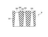
ところで、COR処理は、従来、チャンバー内の圧力が10〜100mTorr(1.33〜13.3Pa)、半導体ウエハの温度が20〜40℃、全ガスの流量が100〜200sccm(mL/min)とする条件が採用されていたが、パターンの微細化とともにパターン底面でのエッチレートが減少し、パターン底面で酸化シリコン膜が残存してしまうという不都合が発生することがある。図5は、50nm以下のパターンに対し、従来条件でCOR処理を行った後に熱処理してエッチングしたときのパターンの状態を示す図である。この図に示すように、エッチングによって得られたパターン205の底部に熱酸化膜のエッチング残り206が生じている。 By the way, in the COR processing, the pressure in the chamber is conventionally 10 to 100 mTorr (1.33 to 13.3 Pa), the temperature of the semiconductor wafer is 20 to 40 ° C., and the flow rate of all gases is 100 to 200 sccm (mL / min). However, there are cases where the etching rate at the bottom of the pattern decreases with the miniaturization of the pattern and the silicon oxide film remains on the bottom of the pattern. FIG. 5 is a diagram showing a pattern state when a pattern of 50 nm or less is subjected to a COR process under a conventional condition and then subjected to a heat treatment and etching. As shown in this figure, an
このようなエッチング残りは、通常、処理の温度を上昇させてエッチングレートを上昇させることにより解消される。 Such etching residue is usually eliminated by increasing the etching temperature by increasing the processing temperature.
しかし、温度を上昇させると、図6に示すように、エッチング残りは解消されるものの、エッチングの形状性が悪化してしまうことが判明した。 However, it has been found that when the temperature is raised, the etching residue is eliminated as shown in FIG. 6, but the etching shape deteriorates.
そこで、エッチング性とエッチングの形状性を両立すべく検討した。
その結果、温度および反応ガスの量を基本的に変化させず、圧力を上昇させることにより、エッチング性とエッチングの形状性を両立できることが見出された。Therefore, studies were made to achieve both etching properties and etching shape.
As a result, it has been found that the etching property and the etching shape can be compatible by increasing the pressure without basically changing the temperature and the amount of the reaction gas.
すなわち、温度が20〜40℃では、反応種(HFおよびNH3)は吸着しやすいため、熱酸化膜のパターンエッチングの際に、パターンの底部でエッチングが進みにくくなり、エッチング残りが発生する。これを防止するために温度を上昇させると、吸着よりも反応が支配的となるため、エッチング残りが生じずに熱酸化膜をエッチングすることができる。しかし、温度を上昇させることにより、TEOS−SiO2膜もエッチングされ、選択性の高いエッチングが困難となってエッチングの形状性(垂直性)が悪化してしまう。That is, when the temperature is 20 to 40 ° C., the reactive species (HF and NH3 ) are easily adsorbed, so that during the pattern etching of the thermal oxide film, it is difficult for the etching to proceed at the bottom of the pattern, resulting in an etching residue. When the temperature is raised to prevent this, the reaction becomes more dominant than the adsorption, so that the thermal oxide film can be etched without any etching residue. However, by raising the temperature, the TEOS-SiO2 film is also etched, and etching with high selectivity becomes difficult, and the etching shape (verticality) is deteriorated.
これに対して、温度を上げずに圧力を上げた場合には、反応種の平均自由行程が短くなるため、反応種の移動が制限されて直進性が高くなり、パターン底部の熱酸化膜に有効に作用するとともにエッチングの垂直性がより高くなるのである。 On the other hand, when the pressure is increased without increasing the temperature, the mean free path of the reactive species is shortened, so that the movement of the reactive species is limited, and the straightness is increased, and the thermal oxide film at the bottom of the pattern is increased. It works effectively and the verticality of etching becomes higher.
このため、本実施形態では、チャンバー40内の圧力を上昇させることにより、エッチング残りを解消するとともに、エッチングの形状性を良好なものとする。すなわち、反応ガスであるHFガスおよびNH3ガスの流量および処理温度を維持したまま、希釈ガスの量を増加させてチャンバー40内の圧力を上昇させることにより、エッチング性およびエッチングの形状性を上昇させることができる。For this reason, in this embodiment, by raising the pressure in the
具体的な条件としては、処理温度:40℃以下、好ましくは35℃以下、HFガス流量:10〜100sccm(mL/min)、NH3ガス流量:10〜100sccm(mL/min)とし、希釈ガスであるArガスおよびN2ガスのトータル流量を増加して、チャンバー40内の圧力を200mTorr(26.7Pa)以上とすることが好ましい。より好ましくは300mTorr(40.0Pa)以上である。As specific conditions, treatment temperature: 40 ° C. or less, preferably 35 ° C. or less, HF gas flow rate: 10 to 100 sccm (mL / min), NH3 gas flow rate: 10 to 100 sccm (mL / min), dilution gas It is preferable to increase the total flow rate of Ar gas and N2 gas, and to set the pressure in the
このときの希釈ガスであるArガスおよびN2ガスのトータル流量は、500sccm(mL/min)以上であることが好ましく、800sccm(mL/min)以上であることがより好ましい。また、HFガス分圧:5〜50mTorr(0.67〜6.7Pa)、NH3ガス分圧:5〜50mTorr(0.67〜6.7Pa)、希釈ガス分圧:200mTorr(26.7Pa)以上であることが好ましい。At this time, the total flow rate of the Ar gas and N2 gas which are dilution gases is preferably 500 sccm (mL / min) or more, and more preferably 800 sccm (mL / min) or more. HF gas partial pressure: 5 to 50 mTorr (0.67 to 6.7 Pa), NH3 gas partial pressure: 5 to 50 mTorr (0.67 to 6.7 Pa), dilution gas partial pressure: 200 mTorr (26.7 Pa) The above is preferable.
実際に、温度:40℃以下、HFガスの流量:10〜100sccm(mL/min)、NH3ガスの流量:10〜100sccm(mL/min)で固定し、圧力を変化させてCOR処理を行った。条件Aは、圧力を10〜100mTorrとした従来条件、条件Bは、圧力を200mTorr以上とした高圧力条件である。その後、PHT処理装置で熱処理を行って、反応生成物であるAFSを除去した。Actually, the temperature is fixed at 40 ° C. or less, the flow rate of HF gas is 10 to 100 sccm (mL / min), the flow rate of NH3 gas is 10 to 100 sccm (mL / min), and COR processing is performed by changing the pressure. It was. Condition A is a conventional condition where the pressure is 10 to 100 mTorr, and Condition B is a high pressure condition where the pressure is 200 mTorr or more. Thereafter, heat treatment was performed with a PHT treatment apparatus to remove AFS as a reaction product.
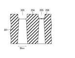
図7および図8は、これらの条件でエッチングを行った後のパターンの状態を示す模式図である。これらに示すように、パターン205の垂直性はいずれも良好であるが、従来条件である条件Aでは、パターンサイズが50nmより大きいときには、パターン205の底部に丸みが形成される程度であるものの、パターンサイズが50nmより小さいときには、熱酸化膜のエッチング残り206が生じた。これに対し、条件Bではパターンサイズが50nmより小さくても熱酸化膜のエッチング残りが生じなかった。このことから、エッチング残りと形状性を両立するためには、高圧化が有効であることが確認された。 7 and 8 are schematic views showing the state of the pattern after etching is performed under these conditions. As shown in these figures, the verticality of the
以上のように、本実施形態によれば、希釈ガスの量を調整して、チャンバー内の圧力を調整するので、エッチング残りが存在せず、かつ垂直性の高いエッチングを行うことができる。 As described above, according to the present embodiment, since the pressure in the chamber is adjusted by adjusting the amount of the dilution gas, etching residue does not exist and etching with high perpendicularity can be performed.
なお、本発明は上記実施形態に限定されることなく種々変形可能である。例えば、上記実施形態では、シャロートレンチアイソレーション構造の熱酸化膜のエッチングに本発明を適用したが、他の構造におけるシリコン酸化膜のエッチングにも適用できるし、熱酸化膜に限らず、他のシリコン酸化膜のエッチングに適用することも可能である。また、希釈ガスとしてArガスおよびN2ガスを用いたが、Arガスのみ、またはN2ガスのみであってもよく、また、他の不活性ガスを用いても、Arガス、N2ガスおよび他の不活性ガスの2種以上を用いてもよい。さらに、上記実施形態では、被処理体を1枚ずつ連続的に搬送する例について示したが、2枚以上ずつ連続して搬送するものであってもよい。The present invention can be variously modified without being limited to the above embodiment. For example, in the above embodiment, the present invention is applied to the etching of the thermal oxide film having the shallow trench isolation structure. However, the present invention can also be applied to the etching of the silicon oxide film in other structures, and is not limited to the thermal oxide film. It is also possible to apply to etching of a silicon oxide film. Further, although Ar gas and N2 gas are used as the dilution gas, only Ar gas or N2 gas may be used, and even if other inert gas is used, Ar gas, N2 gas and Two or more other inert gases may be used. Furthermore, in the said embodiment, although the example which conveys a to-be-processed object one by one continuously was shown, you may convey two or more sheets continuously.
1;処理システム、2;搬入出部、3;ロードロック室、4;PHT処理装置、5;COR処理装置、11;第1ウエハ搬送機構、17;第2ウエハ搬送機構、40;チャンバー、43;ガス供給機構、44;排気機構、56;シャワーヘッド、73:HFガス供給源、74;NH3ガス供給源、77;Arガス供給源、78;N2ガス供給源、86a,86b:キャパシタンスマノメータ、90;制御部、201;シリコン基板、202;熱酸化膜、203;シャロートレンチ、204;TEOS−SiO2膜、205;パターン、206;エッチング残り、W;半導体ウエハDESCRIPTION OF SYMBOLS 1; Processing system, 2; Loading / unloading part, 3; Load lock chamber, 4; PHT processing apparatus, 5; COR processing apparatus, 11: 1st wafer conveyance mechanism, 17: 2nd wafer conveyance mechanism, 40; ; gas supply mechanism, 44; exhaust mechanism, 56; showerhead, 73: HF gas supply source, 74; NH3 gas supply source, 77; Ar gas supply source, 78;N 2 gas supply source, 86a, 86b:
Claims (6)
Translated fromJapanese前記反応させる処理の、前記チャンバー内の圧力、処理温度、ならびに前記HFガス、前記NH3ガス、および希釈ガスの流量の条件が、その後前記分解除去する処理を行ってエッチング残りが存在する所定条件である場合に、
前記反応させる処理の条件を、前記処理温度、および前記HFガスおよび前記NH3ガスの流量を前記所定条件に維持したまま、前記希釈ガスの量を前記所定条件から増加させて、前記チャンバー内の圧力を上昇させた条件にして前記反応させる処理を行い、その後前記分解除去する処理を行うことにより、前記エッチング残りを解消するとともに、垂直性の高いエッチング形状となるようにする、ガス処理方法。An object to be processed having a patterned silicon oxide film formed on the surface is accommodated in the chamber, and HF gas and NH3 gas, which are reaction gases, and a dilution gas are supplied into the chamber, and these and the silicon oxide A gas treatment methodfor etching thesilicon oxide film by performing a process of reacting with the film and then performing a process of heating and decomposing and removing the reaction product generated by the reaction,
The conditions of the pressure in the chamber, the processing temperature, and the flow rates of the HF gas, the NH3 gas, and the dilution gas of theprocessing to be reacted arepredetermined conditions inwhich etchingremoval is performed after the decomposition and removal processing is performed. Ifit is,
The process conditions for the reaction areset such that the amount of the dilution gas is increasedfrom thepredetermined condition while maintaining the processing temperature and the flow rates of the HF gas and the NH3 gas at thepredetermined condition .It performs processing forprevious SL reactionin the conditions to increase the pressure,followed byperforming the process of the decomposition and removal, as well as eliminate the etching residue, so-high vertical etching shape, gas treatment method .
Priority Applications (1)
| Application Number | Priority Date | Filing Date | Title |
|---|---|---|---|
| JP2014516713AJP6110848B2 (en) | 2012-05-23 | 2013-04-04 | Gas processing method |
Applications Claiming Priority (4)
| Application Number | Priority Date | Filing Date | Title |
|---|---|---|---|
| JP2012117990 | 2012-05-23 | ||
| JP2012117990 | 2012-05-23 | ||
| PCT/JP2013/060294WO2013175872A1 (en) | 2012-05-23 | 2013-04-04 | Gas treatment method |
| JP2014516713AJP6110848B2 (en) | 2012-05-23 | 2013-04-04 | Gas processing method |
Publications (2)
| Publication Number | Publication Date |
|---|---|
| JPWO2013175872A1 JPWO2013175872A1 (en) | 2016-01-12 |
| JP6110848B2true JP6110848B2 (en) | 2017-04-05 |
Family
ID=49623576
Family Applications (1)
| Application Number | Title | Priority Date | Filing Date |
|---|---|---|---|
| JP2014516713AActiveJP6110848B2 (en) | 2012-05-23 | 2013-04-04 | Gas processing method |
Country Status (5)
| Country | Link |
|---|---|
| US (1) | US9384993B2 (en) |
| JP (1) | JP6110848B2 (en) |
| KR (1) | KR101707295B1 (en) |
| TW (1) | TWI600084B (en) |
| WO (1) | WO2013175872A1 (en) |
Families Citing this family (9)
| Publication number | Priority date | Publication date | Assignee | Title |
|---|---|---|---|---|
| US10290553B2 (en) | 2015-06-24 | 2019-05-14 | Tokyo Electron Limited | System and method of determining process completion of post heat treatment of a dry etch process |
| KR102786696B1 (en)* | 2016-02-01 | 2025-03-25 | 도쿄엘렉트론가부시키가이샤 | System and method for determining completion of post-heat treatment process of dry etching process |
| JP6561093B2 (en)* | 2017-07-24 | 2019-08-14 | 東京エレクトロン株式会社 | Method for removing silicon oxide film |
| US10607851B2 (en) | 2017-08-25 | 2020-03-31 | Micron Technology, Inc. | Vapor-etch cyclic process |
| JP7113681B2 (en)* | 2018-06-28 | 2022-08-05 | 株式会社日立ハイテク | Etching method and etching apparatus |
| US10854442B2 (en) | 2018-06-29 | 2020-12-01 | Taiwan Semiconductor Manufacturing Co., Ltd. | Orientation chamber of substrate processing system with purging function |
| JP7415594B2 (en)* | 2020-01-24 | 2024-01-17 | 東京エレクトロン株式会社 | Substrate processing method and substrate processing apparatus |
| JP2023087228A (en)* | 2021-12-13 | 2023-06-23 | 東京エレクトロン株式会社 | Gas treatment method and gas treatment device |
| JP2025068463A (en)* | 2023-10-16 | 2025-04-28 | 東京エレクトロン株式会社 | Etching method and etching apparatus |
Family Cites Families (18)
| Publication number | Priority date | Publication date | Assignee | Title |
|---|---|---|---|---|
| US7494560B2 (en)* | 2002-11-27 | 2009-02-24 | International Business Machines Corporation | Non-plasma reaction apparatus and method |
| KR101046523B1 (en) | 2003-04-22 | 2011-07-04 | 도쿄엘렉트론가부시키가이샤 | Removal method of chemical oxide |
| JP4833512B2 (en)* | 2003-06-24 | 2011-12-07 | 東京エレクトロン株式会社 | To-be-processed object processing apparatus, to-be-processed object processing method, and to-be-processed object conveyance method |
| US7510972B2 (en)* | 2005-02-14 | 2009-03-31 | Tokyo Electron Limited | Method of processing substrate, post-chemical mechanical polishing cleaning method, and method of and program for manufacturing electronic device |
| JP4860219B2 (en)* | 2005-02-14 | 2012-01-25 | 東京エレクトロン株式会社 | Substrate processing method, electronic device manufacturing method, and program |
| US7622392B2 (en)* | 2005-02-18 | 2009-11-24 | Tokyo Electron Limited | Method of processing substrate, method of manufacturing solid-state imaging device, method of manufacturing thin film device, and programs for implementing the methods |
| JP2007201168A (en)* | 2006-01-26 | 2007-08-09 | Sony Corp | Natural oxide film removing method and semiconductor device manufacturing method |
| US7718032B2 (en)* | 2006-06-22 | 2010-05-18 | Tokyo Electron Limited | Dry non-plasma treatment system and method of using |
| JP5084250B2 (en) | 2006-12-26 | 2012-11-28 | 東京エレクトロン株式会社 | Gas processing apparatus, gas processing method, and storage medium |
| US7786016B2 (en)* | 2007-01-11 | 2010-08-31 | Micron Technology, Inc. | Methods of uniformly removing silicon oxide and a method of removing a sacrificial oxide |
| JP4949091B2 (en)* | 2007-03-16 | 2012-06-06 | 東京エレクトロン株式会社 | Substrate processing apparatus, substrate processing method, and recording medium |
| US7899637B2 (en)* | 2007-06-13 | 2011-03-01 | Tokyo Electron Limited | Method and apparatus for creating a gate optimization evaluation library |
| US8026180B2 (en)* | 2007-07-12 | 2011-09-27 | Micron Technology, Inc. | Methods of modifying oxide spacers |
| US7765077B2 (en)* | 2007-09-21 | 2010-07-27 | Tokyo Electron Limited | Method and apparatus for creating a Spacer-Optimization (S-O) library |
| JP5374039B2 (en)* | 2007-12-27 | 2013-12-25 | 東京エレクトロン株式会社 | Substrate processing method, substrate processing apparatus, and storage medium |
| JP4968861B2 (en)* | 2009-03-19 | 2012-07-04 | 東京エレクトロン株式会社 | Substrate etching method and system |
| US20110061810A1 (en)* | 2009-09-11 | 2011-03-17 | Applied Materials, Inc. | Apparatus and Methods for Cyclical Oxidation and Etching |
| KR20130010362A (en)* | 2011-07-18 | 2013-01-28 | 삼성전자주식회사 | Method for fabricating semiconductor device |
- 2013
- 2013-04-04KRKR1020147032540Apatent/KR101707295B1/enactiveActive
- 2013-04-04WOPCT/JP2013/060294patent/WO2013175872A1/enactiveApplication Filing
- 2013-04-04JPJP2014516713Apatent/JP6110848B2/enactiveActive
- 2013-05-16TWTW102117368Apatent/TWI600084B/enactive
- 2014
- 2014-11-21USUS14/550,778patent/US9384993B2/enactiveActive
Also Published As
| Publication number | Publication date |
|---|---|
| KR20150022773A (en) | 2015-03-04 |
| JPWO2013175872A1 (en) | 2016-01-12 |
| TW201409568A (en) | 2014-03-01 |
| US20150079801A1 (en) | 2015-03-19 |
| US9384993B2 (en) | 2016-07-05 |
| KR101707295B1 (en) | 2017-02-15 |
| WO2013175872A1 (en) | 2013-11-28 |
| TWI600084B (en) | 2017-09-21 |
Similar Documents
| Publication | Publication Date | Title |
|---|---|---|
| JP6110848B2 (en) | Gas processing method | |
| CN110581067B (en) | Etching method and etching apparatus | |
| JP6139986B2 (en) | Etching method | |
| TWI648791B (en) | Etching method | |
| TWI806835B (en) | Etching method and manufacturing method of DRAM capacitor | |
| JP5084250B2 (en) | Gas processing apparatus, gas processing method, and storage medium | |
| JP6494226B2 (en) | Etching method | |
| JP6073172B2 (en) | Etching method | |
| JP6097192B2 (en) | Etching method | |
| KR101802580B1 (en) | Etching method and storage medium | |
| WO2016056401A1 (en) | Etching method | |
| WO2013183437A1 (en) | Gas treatment method | |
| JP5997555B2 (en) | Etching apparatus and etching method | |
| TW201941283A (en) | Etching method | |
| WO2015186461A1 (en) | Method for etching | |
| JP2015073035A (en) | Etching method | |
| JP2022066687A (en) | Etching method and etching equipment | |
| JP2014013841A (en) | Processing method and conditioning method |
Legal Events
| Date | Code | Title | Description |
|---|---|---|---|
| A521 | Request for written amendment filed | Free format text:JAPANESE INTERMEDIATE CODE: A523 Effective date:20160304 | |
| A621 | Written request for application examination | Free format text:JAPANESE INTERMEDIATE CODE: A621 Effective date:20160304 | |
| A131 | Notification of reasons for refusal | Free format text:JAPANESE INTERMEDIATE CODE: A131 Effective date:20161025 | |
| A521 | Request for written amendment filed | Free format text:JAPANESE INTERMEDIATE CODE: A523 Effective date:20161214 | |
| TRDD | Decision of grant or rejection written | ||
| A01 | Written decision to grant a patent or to grant a registration (utility model) | Free format text:JAPANESE INTERMEDIATE CODE: A01 Effective date:20170307 | |
| A61 | First payment of annual fees (during grant procedure) | Free format text:JAPANESE INTERMEDIATE CODE: A61 Effective date:20170310 | |
| R150 | Certificate of patent or registration of utility model | Ref document number:6110848 Country of ref document:JP Free format text:JAPANESE INTERMEDIATE CODE: R150 | |
| R250 | Receipt of annual fees | Free format text:JAPANESE INTERMEDIATE CODE: R250 | |
| R250 | Receipt of annual fees | Free format text:JAPANESE INTERMEDIATE CODE: R250 | |
| R250 | Receipt of annual fees | Free format text:JAPANESE INTERMEDIATE CODE: R250 | |
| R250 | Receipt of annual fees | Free format text:JAPANESE INTERMEDIATE CODE: R250 | |
| R250 | Receipt of annual fees | Free format text:JAPANESE INTERMEDIATE CODE: R250 | |
| R250 | Receipt of annual fees | Free format text:JAPANESE INTERMEDIATE CODE: R250 |