JP6110540B2 - Semiconductor wafer processing apparatus and method for processing semiconductor wafer - Google Patents
Semiconductor wafer processing apparatus and method for processing semiconductor waferDownload PDFInfo
- Publication number
- JP6110540B2 JP6110540B2JP2016074072AJP2016074072AJP6110540B2JP 6110540 B2JP6110540 B2JP 6110540B2JP 2016074072 AJP2016074072 AJP 2016074072AJP 2016074072 AJP2016074072 AJP 2016074072AJP 6110540 B2JP6110540 B2JP 6110540B2
- Authority
- JP
- Japan
- Prior art keywords
- distribution unit
- plasma generation
- generation space
- gas distribution
- semiconductor wafer
- Prior art date
- Legal status (The legal status is an assumption and is not a legal conclusion. Google has not performed a legal analysis and makes no representation as to the accuracy of the status listed.)
- Active
Links
- 238000000034methodMethods0.000titleclaimsdescription78
- 238000012545processingMethods0.000titleclaimsdescription75
- 239000004065semiconductorSubstances0.000titleclaimsdescription43
- 238000009826distributionMethods0.000claimsdescription194
- 230000008569processEffects0.000claimsdescription65
- 239000012530fluidSubstances0.000claimsdescription27
- 239000000758substrateSubstances0.000claimsdescription15
- 238000013459approachMethods0.000claimsdescription4
- 230000002093peripheral effectEffects0.000claims3
- 239000007787solidSubstances0.000claims2
- 230000004888barrier functionEffects0.000claims1
- 239000007789gasSubstances0.000description296
- 235000012431wafersNutrition0.000description40
- 150000002500ionsChemical class0.000description32
- 230000007935neutral effectEffects0.000description24
- 230000004907fluxEffects0.000description22
- 239000000463materialSubstances0.000description16
- 230000009977dual effectEffects0.000description11
- 238000010494dissociation reactionMethods0.000description9
- 230000005593dissociationsEffects0.000description9
- 238000004891communicationMethods0.000description8
- 229910052751metalInorganic materials0.000description6
- 239000002184metalSubstances0.000description6
- VYPSYNLAJGMNEJ-UHFFFAOYSA-Nsilicon dioxideInorganic materialsO=[Si]=OVYPSYNLAJGMNEJ-UHFFFAOYSA-N0.000description6
- 239000011248coating agentSubstances0.000description5
- 238000000576coating methodMethods0.000description5
- 239000004020conductorSubstances0.000description5
- 238000001816coolingMethods0.000description5
- 239000000203mixtureSubstances0.000description5
- 229910052710siliconInorganic materials0.000description4
- 239000010703siliconSubstances0.000description4
- YCKRFDGAMUMZLT-UHFFFAOYSA-NFluorine atomChemical compound[F]YCKRFDGAMUMZLT-UHFFFAOYSA-N0.000description3
- XUIMIQQOPSSXEZ-UHFFFAOYSA-NSiliconChemical compound[Si]XUIMIQQOPSSXEZ-UHFFFAOYSA-N0.000description3
- 229910052782aluminiumInorganic materials0.000description3
- XAGFODPZIPBFFR-UHFFFAOYSA-NaluminiumChemical compound[Al]XAGFODPZIPBFFR-UHFFFAOYSA-N0.000description3
- 230000015572biosynthetic processEffects0.000description3
- 239000012809cooling fluidSubstances0.000description3
- SIWVEOZUMHYXCS-UHFFFAOYSA-Noxo(oxoyttriooxy)yttriumChemical compoundO=[Y]O[Y]=OSIWVEOZUMHYXCS-UHFFFAOYSA-N0.000description3
- 239000010453quartzSubstances0.000description3
- 238000000926separation methodMethods0.000description3
- HBMJWWWQQXIZIP-UHFFFAOYSA-Nsilicon carbideChemical compound[Si+]#[C-]HBMJWWWQQXIZIP-UHFFFAOYSA-N0.000description3
- 229910010271silicon carbideInorganic materials0.000description3
- 229910052814silicon oxideInorganic materials0.000description3
- 229910001220stainless steelInorganic materials0.000description3
- 239000010935stainless steelSubstances0.000description3
- 239000000126substanceSubstances0.000description3
- 239000002470thermal conductorSubstances0.000description3
- 238000007792additionMethods0.000description2
- 238000010292electrical insulationMethods0.000description2
- 238000002955isolationMethods0.000description2
- 238000004519manufacturing processMethods0.000description2
- 230000007246mechanismEffects0.000description2
- 230000035515penetrationEffects0.000description2
- 230000001681protective effectEffects0.000description2
- 238000006467substitution reactionMethods0.000description2
- XLYOFNOQVPJJNP-UHFFFAOYSA-NwaterSubstancesOXLYOFNOQVPJJNP-UHFFFAOYSA-N0.000description2
- 230000002411adverseEffects0.000description1
- 238000000231atomic layer depositionMethods0.000description1
- 230000000903blocking effectEffects0.000description1
- 230000001419dependent effectEffects0.000description1
- 238000010586diagramMethods0.000description1
- 238000009792diffusion processMethods0.000description1
- 238000005516engineering processMethods0.000description1
- 238000005530etchingMethods0.000description1
- 238000010438heat treatmentMethods0.000description1
- 230000006698inductionEffects0.000description1
- 238000009616inductively coupled plasmaMethods0.000description1
- 238000003780insertionMethods0.000description1
- 230000037431insertionEffects0.000description1
- 238000009434installationMethods0.000description1
- 150000002739metalsChemical class0.000description1
- 239000003566sealing materialSubstances0.000description1
- 230000036962time dependentEffects0.000description1
Images


Classifications
- H—ELECTRICITY
- H01—ELECTRIC ELEMENTS
- H01J—ELECTRIC DISCHARGE TUBES OR DISCHARGE LAMPS
- H01J37/00—Discharge tubes with provision for introducing objects or material to be exposed to the discharge, e.g. for the purpose of examination or processing thereof
- H01J37/32—Gas-filled discharge tubes
- H01J37/32431—Constructional details of the reactor
- H01J37/3244—Gas supply means
- H01J37/32449—Gas control, e.g. control of the gas flow
- H—ELECTRICITY
- H01—ELECTRIC ELEMENTS
- H01J—ELECTRIC DISCHARGE TUBES OR DISCHARGE LAMPS
- H01J37/00—Discharge tubes with provision for introducing objects or material to be exposed to the discharge, e.g. for the purpose of examination or processing thereof
- H01J37/32—Gas-filled discharge tubes
- H01J37/32009—Arrangements for generation of plasma specially adapted for examination or treatment of objects, e.g. plasma sources
- H01J37/32082—Radio frequency generated discharge
- H01J37/32091—Radio frequency generated discharge the radio frequency energy being capacitively coupled to the plasma
- H—ELECTRICITY
- H01—ELECTRIC ELEMENTS
- H01J—ELECTRIC DISCHARGE TUBES OR DISCHARGE LAMPS
- H01J37/00—Discharge tubes with provision for introducing objects or material to be exposed to the discharge, e.g. for the purpose of examination or processing thereof
- H01J37/32—Gas-filled discharge tubes
- H01J37/32431—Constructional details of the reactor
- H01J37/32697—Electrostatic control
- H—ELECTRICITY
- H01—ELECTRIC ELEMENTS
- H01J—ELECTRIC DISCHARGE TUBES OR DISCHARGE LAMPS
- H01J37/00—Discharge tubes with provision for introducing objects or material to be exposed to the discharge, e.g. for the purpose of examination or processing thereof
- H01J37/32—Gas-filled discharge tubes
- H01J37/32431—Constructional details of the reactor
- H01J37/32715—Workpiece holder
- H—ELECTRICITY
- H01—ELECTRIC ELEMENTS
- H01J—ELECTRIC DISCHARGE TUBES OR DISCHARGE LAMPS
- H01J37/00—Discharge tubes with provision for introducing objects or material to be exposed to the discharge, e.g. for the purpose of examination or processing thereof
- H01J37/32—Gas-filled discharge tubes
- H01J37/32431—Constructional details of the reactor
- H01J37/32798—Further details of plasma apparatus not provided for in groups H01J37/3244 - H01J37/32788; special provisions for cleaning or maintenance of the apparatus
- H01J37/32816—Pressure
- H01J37/32834—Exhausting
- H—ELECTRICITY
- H01—ELECTRIC ELEMENTS
- H01L—SEMICONDUCTOR DEVICES NOT COVERED BY CLASS H10
- H01L21/00—Processes or apparatus adapted for the manufacture or treatment of semiconductor or solid state devices or of parts thereof
- H01L21/67—Apparatus specially adapted for handling semiconductor or electric solid state devices during manufacture or treatment thereof; Apparatus specially adapted for handling wafers during manufacture or treatment of semiconductor or electric solid state devices or components ; Apparatus not specifically provided for elsewhere
- H01L21/67005—Apparatus not specifically provided for elsewhere
- H01L21/67011—Apparatus for manufacture or treatment
- H01L21/67017—Apparatus for fluid treatment
- H01L21/67063—Apparatus for fluid treatment for etching
- H01L21/67069—Apparatus for fluid treatment for etching for drying etching
- H—ELECTRICITY
- H01—ELECTRIC ELEMENTS
- H01L—SEMICONDUCTOR DEVICES NOT COVERED BY CLASS H10
- H01L21/00—Processes or apparatus adapted for the manufacture or treatment of semiconductor or solid state devices or of parts thereof
- H01L21/67—Apparatus specially adapted for handling semiconductor or electric solid state devices during manufacture or treatment thereof; Apparatus specially adapted for handling wafers during manufacture or treatment of semiconductor or electric solid state devices or components ; Apparatus not specifically provided for elsewhere
- H01L21/67005—Apparatus not specifically provided for elsewhere
- H01L21/67242—Apparatus for monitoring, sorting or marking
- H01L21/67259—Position monitoring, e.g. misposition detection or presence detection
- H—ELECTRICITY
- H01—ELECTRIC ELEMENTS
- H01L—SEMICONDUCTOR DEVICES NOT COVERED BY CLASS H10
- H01L21/00—Processes or apparatus adapted for the manufacture or treatment of semiconductor or solid state devices or of parts thereof
- H01L21/67—Apparatus specially adapted for handling semiconductor or electric solid state devices during manufacture or treatment thereof; Apparatus specially adapted for handling wafers during manufacture or treatment of semiconductor or electric solid state devices or components ; Apparatus not specifically provided for elsewhere
- H01L21/683—Apparatus specially adapted for handling semiconductor or electric solid state devices during manufacture or treatment thereof; Apparatus specially adapted for handling wafers during manufacture or treatment of semiconductor or electric solid state devices or components ; Apparatus not specifically provided for elsewhere for supporting or gripping
- H01L21/6831—Apparatus specially adapted for handling semiconductor or electric solid state devices during manufacture or treatment thereof; Apparatus specially adapted for handling wafers during manufacture or treatment of semiconductor or electric solid state devices or components ; Apparatus not specifically provided for elsewhere for supporting or gripping using electrostatic chucks
- H—ELECTRICITY
- H01—ELECTRIC ELEMENTS
- H01L—SEMICONDUCTOR DEVICES NOT COVERED BY CLASS H10
- H01L22/00—Testing or measuring during manufacture or treatment; Reliability measurements, i.e. testing of parts without further processing to modify the parts as such; Structural arrangements therefor
- H01L22/20—Sequence of activities consisting of a plurality of measurements, corrections, marking or sorting steps
- H01L22/26—Acting in response to an ongoing measurement without interruption of processing, e.g. endpoint detection, in-situ thickness measurement
Landscapes
- Engineering & Computer Science (AREA)
- Physics & Mathematics (AREA)
- Plasma & Fusion (AREA)
- Chemical & Material Sciences (AREA)
- Analytical Chemistry (AREA)
- Computer Hardware Design (AREA)
- Manufacturing & Machinery (AREA)
- Microelectronics & Electronic Packaging (AREA)
- Power Engineering (AREA)
- Condensed Matter Physics & Semiconductors (AREA)
- General Physics & Mathematics (AREA)
- Plasma Technology (AREA)
- Drying Of Semiconductors (AREA)
- Chemical Vapour Deposition (AREA)
- Particle Accelerators (AREA)
Description
Translated fromJapanese半導体ウエハの製造に使用されている現行のプラズマ処理システムは、ラジカル分離、ラジカルフラックス、イオンエネルギ、及びウエハに供給されるイオンフラックスを制御するために、相互に大きく依存しあう制御パラメータに頼っている。例えば、現行のプラズマ処理システムは、ウエハの存在下で発生する単種のプラズマを制御することによって、必要なラジカル分離、ラジカルフラックス、イオンエネルギ、及びイオンフラックスを実現しようと試みている。あいにく、イオンの発生及びプラズマの密度には、化学物質の解離及びラジカルの形成が結び付いており、これらは、所望のプラズマ処理条件を達成するために連携しあうことは稀である。 Current plasma processing systems used in the manufacture of semiconductor wafers rely on mutually dependent control parameters to control radical separation, radical flux, ion energy, and ion flux delivered to the wafer. Yes. For example, current plasma processing systems attempt to achieve the necessary radical separation, radical flux, ion energy, and ion flux by controlling a single type of plasma generated in the presence of a wafer. Unfortunately, ion generation and plasma density are associated with chemical dissociation and radical formation, which rarely work together to achieve the desired plasma processing conditions.
例えば、現行のプラズマ処理システムでは、化学物質の解離が高いほど、より高電力の印加が必要とされ、これは、ひいては、より高密度のプラズマを発生させるので、より高い化学物質解離と、より低いイオン密度とを、同じプラズマのなかで同時に得ることは困難である。また、現行のプラズマ処理システムでは、制御パラメータ間における大きな相互依存性によって、より小さい技術ノード用途における処理窓及び/又は生産能力が制限される。以上から、イオンフラックスに対するラジカル/中性フラックスの独立制御を提供するプラズマ処理システムが必要とされている。 For example, in current plasma processing systems, the higher the chemical dissociation, the higher the power required, which in turn generates a higher density plasma, and therefore higher chemical dissociation and more It is difficult to obtain a low ion density at the same time in the same plasma. Also, in current plasma processing systems, the large interdependencies between control parameters limit processing windows and / or production capacity in smaller technology node applications. Accordingly, there is a need for a plasma processing system that provides independent control of radical / neutral flux with respect to ion flux.
一実施形態では、半導体ウエハ処理装置が開示される。装置は、第1のプラズマ発生空間に暴露される第1の電極を含む。第1の電極は、無線周波数(RF)電力を第1のプラズマ発生空間に供給するように定められる。第1の電極は、更に、第1のプラズマプロセスガスを第1のプラズマ発生空間に分配するように定められる。装置は、また、第2のプラズマ発生空間に暴露される第2の電極を含む。第2の電極は、RF電力を第2のプラズマ発生空間に供給するように定められる。第2の電極は、更に、基板を第2のプラズマ発生空間に暴露させて保持するように定められる。装置は、更に、第1のプラズマ発生空間と第2のプラズマ発生空間との間に配されたガス分配ユニットを含む。ガス分配ユニットは、第1のプラズマ発生空間を第2のプラズマ発生空間に流体接続するためにそれぞれガス分配ユニットを通って伸びる貫通穴の配列を含むように定められる。ガス分配ユニットは、第2のプラズマプロセスガスを第2のプラズマ発生空間に分配するように定められたガス供給ポートの配列を含むように定められる。 In one embodiment, a semiconductor wafer processing apparatus is disclosed. The apparatus includes a first electrode that is exposed to a first plasma generation space. The first electrode is defined to supply radio frequency (RF) power to the first plasma generation space. The first electrode is further defined to distribute the first plasma process gas to the first plasma generation space. The apparatus also includes a second electrode that is exposed to the second plasma generation space. The second electrode is defined to supply RF power to the second plasma generation space. The second electrode is further defined to hold the substrate exposed to the second plasma generation space. The apparatus further includes a gas distribution unit disposed between the first plasma generation space and the second plasma generation space. The gas distribution unit is defined to include an array of through holes each extending through the gas distribution unit to fluidly connect the first plasma generation space to the second plasma generation space. The gas distribution unit is defined to include an array of gas supply ports defined to distribute the second plasma process gas to the second plasma generation space.
別の一実施形態では、半導体ウエハ処理のためのシステムが開示される。システムは、内部空洞と、該内部空洞を排出ポンプに流体接続するための排出ポートとを有するように定められたチャンバを含む。システムは、また、チャンバの内部空洞内に配された二重プラズマ処理装置を含む。二重プラズマ処理装置は、上方プラズマ発生空間を含む上方プラズマチャンバを含む。二重プラズマ処理装置は、また、第1のプラズマプロセスガス及びRF電力を上方プラズマ発生空間に供給するために上方プラズマ発生空間の上方に定められたシャワーヘッド電極を含む。二重プラズマ処理装置は、また、下方プラズマ発生空間を含む下方プラズマチャンバを含む。二重プラズマ処理装置は、また、上方プラズマ発生空間と下方プラズマ発生空間との間に配されたガス分配ユニットを含む。ガス分配ユニットは、第2のプラズマプロセスガスを下方プラズマ発生空間に供給するように定められる。ガス分配ユニットは、更に、上方プラズマ発生空間と下方プラズマ発生空間との間で制御された流体連通を提供するように定められる。システムは、更に、下方プラズマ発生空間の下方においてチャンバの内部空洞内に配されたチャックを含む。チャックは、基板を下方プラズマ発生空間に暴露させて保持するように定められる。チャックは、更に、RF電力を下方プラズマ発生空間に供給するように定められる。上方プラズマチャンバ及び下方プラズマチャンバのそれぞれは、上方プラズマ発生空間及び下方プラズマ発生空間をチャンバの内部空洞内へ排気するようにそれぞれ定められる。 In another embodiment, a system for semiconductor wafer processing is disclosed. The system includes a chamber defined to have an internal cavity and an exhaust port for fluidly connecting the internal cavity to an exhaust pump. The system also includes a dual plasma processing apparatus disposed within the interior cavity of the chamber. The dual plasma processing apparatus includes an upper plasma chamber including an upper plasma generation space. The dual plasma processing apparatus also includes a showerhead electrode defined above the upper plasma generation space for supplying a first plasma process gas and RF power to the upper plasma generation space. The dual plasma processing apparatus also includes a lower plasma chamber that includes a lower plasma generation space. The dual plasma processing apparatus also includes a gas distribution unit disposed between the upper plasma generation space and the lower plasma generation space. The gas distribution unit is defined to supply a second plasma process gas to the lower plasma generation space. The gas distribution unit is further defined to provide controlled fluid communication between the upper plasma generation space and the lower plasma generation space. The system further includes a chuck disposed within the interior cavity of the chamber below the lower plasma generation space. The chuck is defined to hold the substrate exposed to the lower plasma generation space. The chuck is further defined to supply RF power to the lower plasma generation space. Each of the upper plasma chamber and the lower plasma chamber is defined to exhaust the upper plasma generation space and the lower plasma generation space into the internal cavity of the chamber.
別の一実施形態では、ガス分配ユニットが開示される。ガス分配ユニットは、上方プラズマ発生空間を下方プラズマ発生空間から分離するように形成された板を含む。板の上表面は、上方プラズマ発生空間の下方境界を提供する。板の下表面は、下方プラズマ発生空間の上方境界を提供する。板は、上方プラズマ発生空間を下方プラズマ発生空間に流体接続するためにそれぞれ板を通って板の上表面から板の下表面へ伸びる貫通穴の配列を含む。板は、また、プラズマプロセスガスを下方プラズマ発生空間に分配するために板の下表面に定められたガス供給ポートの配列に流体接続されたガス供給内部流路を含む。
本発明は、以下の適用例としても実現可能である。
[適用例1]
半導体ウエハ処理装置であって、
第1のプラズマ発生空間に暴露される第1の電極であって、無線周波数(RF)電力を前記第1のプラズマ発生空間に供給するように定められ、更に、第1のプラズマプロセスガスを前記第1のプラズマ発生空間に分配するように定められた第1の電極と、
第2のプラズマ発生空間に暴露される第2の電極であって、RF電力を第2のプラズマ発生空間に供給するように定められ、更に、基板を前記第2のプラズマ発生空間に暴露させて保持するように定められた第2の電極と、
前記第1のプラズマ発生空間と前記第2のプラズマ発生空間との間に配されたガス分配ユニットであって、前記第1のプラズマ発生空間を前記第2のプラズマ発生空間に流体接続するためにそれぞれ前記ガス分配ユニットを通って伸びる貫通穴の配列を含むように定められ、更に、第2のプラズマプロセスガスを前記第2のプラズマ発生空間に分配するように定められたガス供給ポートの配列を含むように定められたガス分配ユニットと、
を備える装置。
[適用例2]
適用例1に記載の装置であって、
前記第1の電極は、前記第1のプラズマ発生空間に面している複数の同心の放射状ゾーン内に配置された複数のガス供給ポートを含むように定められ、各同心放射状ゾーン内の前記ガス供給ポートは、各同心放射状ゾーンへの前記第1のプラズマプロセスガスの供給が独立に制御されるように、それぞれのガス流量制御機器に配管される、装置。
[適用例3]
適用例1に記載の装置であって、
前記第1の電極は、前記第1のプラズマ発生空間の上表面を形成し、
前記第2の電極は、前記第2のプラズマ発生空間の下表面を形成し、
前記ガス分配ユニットは、その上表面が前記第1のプラズマ発生空間の下方境界を提供するように及びその下表面が前記第2のプラズマ発生空間の上方境界を提供するように前記第1のプラズマ発生空間を前記第2のプラズマ発生空間から分離するために形成された板として定められ、前記貫通穴のそれぞれは、前記板を通って前記板の前記上表面から前記板の前記下表面へ伸びる、装置。
[適用例4]
適用例3に記載の装置であって、
前記板は、前記第2のプラズマプロセスガスを前記第2のプラズマ発生空間に分配するために前記板の前記下表面上に定められたガス供給ポートの配列に流体接続されたガス供給内部流路を含む、装置。
[適用例5]
適用例4に記載の装置であって、
前記ガス供給流路は、それぞれの領域における前記ガス供給ポートへの前記第2のプラズマプロセスガスの流量が独立に制御されるように、前記ガス供給ポートの配列を前記板の前記下表面全域にわたり複数の同心領域に流体的に分離するように定められる、装置。
[適用例6]
適用例1に記載の装置であって、
前記ガス分配ユニットは、導電性材料で形成され、前記第1のプラズマ発生空間及び前記第2のプラズマ発生空間の両方のための接地電極を提供するように基準接地電位に電気的に接続される、装置。
[適用例7]
適用例1に記載の装置であって、
前記第1の電極は、第1のRF電源に電気的に接続され、
前記第2の電極は、前記第1のRF電源とは別の第2のRF電源に電気的に接続される、装置。
[適用例8]
適用例1に記載の装置であって、
前記第2の電極は、静電気引力を通じて前記基板を保持するように定められる、装置。
[適用例9]
適用例1に記載の装置であって、
前記第2の電極は、前記第2の電極及び前記ガス分配ユニットの両方に垂直な方向に沿った前記第2のプラズマ発生空間の距離の制御を提供するために、前記ガス分配ユニットに近づく方向及び前記ガス分配ユニットから遠ざかる方向に移動可能である、装置。
[適用例10]
適用例1に記載の装置であって、
前記第1のプラズマ発生空間は、前記第1の電極の半径方向周縁の外側及び前記ガス分配ユニットの半径方向周縁の外側で前記第1のプラズマ発生空間を取り巻くように定められた排出流路を通して排気されるように定められ、
前記半導体ウエハ処理装置は、更に、前記第1のプラズマ発生空間から前記排出流路を通るガスの流れを絞り調整するために前記排出流路内で移動するように定められた圧力スロットルリングを備える装置。
[適用例11]
適用例10に記載の装置であって、更に、
前記第1のプラズマ発生空間内の圧力を測定するように配された圧力測定機器と、
前記圧力測定機器から得られた前記第1のプラズマ発生空間内の測定圧力に基づいて前記排出流路内における前記圧力スロットルリングの位置を制御するように定められたフィードバック制御メカニズムと、
を備える装置。
[適用例12]
適用例1に記載の装置であって、
前記第2のプラズマ発生空間は、前記第2の電極の半径方向周縁の外側及び前記ガス分配ユニットの半径方向周縁の外側で前記第2のプラズマ発生空間を取り巻くように定められたスロット付き流路群を通して排気されるように定められ、
前記半導体ウエハ処理装置は、更に、前記スロット付き流路群にあてがわれたときに前記スロット付き流路群を覆うように定められた圧力制御リングであって、前記第2のプラズマ発生空間から前記スロット付き流路群を通るガスの流れを絞り調整するために前記スロット付き流路群に近づくように及び前記スロット付き流路群から遠ざかるように移動するように定められた圧力制御リングを備える装置。
[適用例13]
適用例12に記載の装置であって、更に、
前記第2のプラズマ発生空間内の圧力を測定するように配された圧力測定機器と、
前記圧力測定機器から得られた前記第2のプラズマ発生空間内の測定圧力に基づいて前記スロット付き流路群に相対的に前記圧力制御リングの位置を制御するように定められたフィードバック制御メカニズムと、
を備える装置。
[適用例14]
適用例1に記載の装置であって、
各貫通穴は、前記第1のプラズマ発生空間に暴露されている前記ガス分配ユニットの上表面から前記第2のプラズマ発生空間に暴露されている前記ガス分配ユニットの下表面へ、前記ガス分配ユニットの前記上表面と前記下表面との間で垂直に伸びる基準方向からずれた角度で伸びるように定められ、前記角度は、各貫通穴の場所において前記基準方向に前記ガス分配ユニットを見通す視線を遮るのに十分な大きさである、装置。
[適用例15]
半導体ウエハ処理のためのシステムであって、
内部空洞と、前記内部空洞を排出ポンプに流体接続するための排出ポートとを有するように定められたチャンバと、
前記チャンバの前記内部空洞内に配された二重プラズマ処理装置であって、
上方プラズマ発生空間を含む上方プラズマチャンバと、
第1のプラズマプロセスガス及び無線周波数(RF)電力を前記上方プラズマ発生空間に供給するために前記上方プラズマ発生空間の上方に定められたシャワーヘッド電極と、
下方プラズマ発生空間を含む下方プラズマチャンバと、
前記上方プラズマ発生空間と前記下方プラズマ発生空間との間に配されたガス分配ユニットであって、第2のプラズマプロセスガスを前記下方プラズマ発生空間に供給するように定められ、更に、前記上方プラズマ発生空間と前記下方プラズマ発生空間との間で制御された流体連通を提供するように定められたガス分配ユニットと、
を含む二重プラズマ処理装置と、
前記下方プラズマ発生空間の下方において前記チャンバの前記内部空洞内に配されたチャックであって、基板を前記下方プラズマ発生空間に暴露させて保持するように定められ、更に、RF電力を前記下方プラズマ発生空間に供給するように定められたチャックと、
を備え、
前記上方プラズマチャンバ及び前記下方プラズマチャンバのそれぞれは、前記上方プラズマ発生空間及び前記下方プラズマ発生空間を前記チャンバの内部空洞内へ排気するようにそれぞれ定められる、システム。
[適用例16]
適用例15に記載のシステムであって、
前記ガス分配ユニットは、導電性材料で形成され、前記上方プラズマ発生空間及び前記下方プラズマ発生空間の両方のための接地電極として機能するように基準接地電位に電気的に接続される、システム。
[適用例17]
適用例15に記載のシステムであって、
前記ガス分配ユニットは、前記上方プラズマ発生空間と前記下方プラズマ発生空間との間で制御された流体連通を提供するために、前記上方プラズマ発生空間に面している前記ガス分配ユニットの上表面から前記下方プラズマ発生空間に面している前記ガス分配ユニットの下表面へ伸びるように形成された貫通穴の配列を含む、システム。
[適用例18]
適用例15に記載のシステムであって、
前記チャックは、前記チャックと前記ガス分配ユニットとの間で垂直方向に前記下方プラズマ発生空間の距離の制御を提供するために、前記ガス分配ユニットに近づく方向及び前記ガス分配ユニットから遠ざかる方向に移動可能である、システム。
[適用例19]
適用例15に記載のシステムであって、
前記上方プラズマチャンバは、前記シャワーヘッド電極の半径方向周縁の外側及び前記ガス分配ユニットの半径方向周縁の外側で前記下方プラズマ発生空間を取り巻くように定められた排出流路を通して排気されるように定められ、
前記システムは、更に、前記上方プラズマ発生空間から前記排出流路を通るガスの流れを絞り調整するために前記排出流路内で移動するように定められた圧力スロットルリングを備えるシステム。
[適用例20]
適用例15に記載のシステムであって、
前記下方プラズマ発生空間は、前記チャックの半径方向周縁の外側及び前記ガス分配ユニットの半径方向周縁の外側で前記下方プラズマ発生空間を取り巻くように定められたスロット付き流路群を通して排気されるように定められ、
前記システムは、更に、前記スロット付き流路群にあてがわれたときに前記スロット付き流路群を覆うように定められた圧力制御リングであって、前記下方プラズマ発生空間から前記スロット付き流路群を通るガスの流れを絞り調整するために前記スロット付き流路群に近づくように及び前記スロット付き流路群から遠ざかるように移動するように定められた圧力制御リングを備えるシステム。
[適用例21]
適用例15に記載のシステムであって、更に、
前記シャワーヘッド電極を通して前記上方プラズマ発生空間にRF電力を供給するために電気的に接続された第1のRF電源と、
前記チャックを通して前記下方プラズマ発生空間にRF電力を供給するために電気的に接続され、前記第1のRF電源から独立している第2のRF電源と、
前記シャワーヘッド電極に流体接続された第1のプラズマプロセスガス供給部と、
前記ガス分配ユニットに流体接続された第2のプラズマプロセスガス供給部と、
を備え、
前記第1のプラズマプロセスガス供給部及び前記第2のプラズマプロセスガス供給部のそれぞれは、前記上方プラズマ発生空間及び前記下方プラズマ発生空間へのプラズマプロセスガスの流量が独立に制御可能であるように、独立に制御可能である、システム。
[適用例22]
ガス分配ユニットであって、
その上表面が前記上方プラズマ発生空間の下方境界を提供するように及びその下表面が前記下方プラズマ発生空間の上方境界を提供するように前記上方プラズマ発生空間を前記下方プラズマ発生空間から分離するために形成された板を備え、
前記板は、前記上方プラズマ発生空間を前記下方プラズマ発生空間に流体接続するためにそれぞれ前記板を通って前記板の前記上表面から前記板の前記下表面へ伸びる貫通穴の配列を含み、
前記板は、プラズマプロセスガスを前記下方プラズマ発生空間に分配するために前記板の前記下表面上に定められたガス供給ポートの配列に流体接続されたガス供給内部流路を含む、ガス分配ユニット。
[適用例23]
適用例22に記載のガス分配ユニットであって、
前記板は、導電性材料で形成され、前記板は、前記上方プラズマ発生空間及び前記下方プラズマ発生空間のそれぞれのための接地電極を提供するために基準接地電位に電気的に接続される、ガス分配ユニット。
[適用例24]
適用例22に記載のガス分配ユニットであって、
前記ガス供給流路及び前記ガス供給ポートは、前記プラズマプロセスガスが前記下方プラズマ発生空間には分配されるが前記上方プラズマ発生空間には分配されないように、前記貫通穴の配列の間に定められる、ガス分配ユニット。
[適用例25]
適用例22に記載のガス分配ユニットであって、
前記ガス供給流路は、それぞれの領域における前記ガス供給ポートへの前記プラズマプロセスガスの流量が独立に制御されるように、前記ガス供給ポートの配列を前記板の前記下表面全域にわたり複数の同心領域に流体的に分離するように定められる、ガス分配ユニット。
[適用例26]
適用例22に記載のガス分配ユニットであって、
各貫通穴は、前記板の前記上表面から前記板の前記下表面へ、前記板の前記上表面と前記下表面との間で垂直に伸びる基準方向からずれた角度で伸びるように定められ、前記角度は、各貫通穴の場所において前記基準方向に前記板を見通す視線を遮るのに十分な大きさである、ガス分配ユニット。
[適用例27]
適用例22に記載のガス分配ユニットであって、更に、
前記板の前記上表面上に配されるように形成された円盤であって、前記円盤を通って伸びる複数の穴パターンを含む円盤を備え、
前記複数の穴パターンのそれぞれは、前記円盤を前記板の前記上表面に対して或る特定の回転位置で前記板の前記上表面上に配することが、前記複数の穴パターンのうちの特定の一パターンを前記板内の対応する貫通穴群と合致させることに相当するように、前記板内の異なる貫通穴群と合致しており、
前記円盤は、前記円盤と前記板との間に熱伝導及び電気伝導が存在するように前記板に固定される、ガス分配ユニット。
[適用例28]
適用例27に記載のガス分配ユニットであって、
前記円盤を通る前記複数の穴パターンのそれぞれは、前記板内の異なる数の又は異なる空間パターンの貫通穴を暴露させるように定められる、ガス分配ユニット。
[適用例29]
適用例22に記載のガス分配ユニットであって、更に、
前記板の前記上表面上に同心状に配されるように形成された、中心円盤及び複数の同心リングを備え、
前記中心円盤及び前記複数の同心リングのそれぞれは、その中を通って伸びる複数の穴パターンをそれぞれ含み、
前記複数の穴パターンのそれぞれは、前記板の前記上表面に対して或る特定の回転位置で前記中心円盤及び前記同心リングのそれぞれを前記板の前記上表面上に配することが、前記複数の穴パターンのうちの特定の一パターンを前記板内の対応する貫通穴群と合致させることに相当するように、前記板内の異なる貫通穴群と合致しており、
前記中心円盤及び前記幾つかの同心リングのそれぞれは、前記板と前記中心円盤及び前記幾つかの同心リングのそれぞれとの間に熱伝導及び電気伝導が存在するように前記板に固定される、ガス分配ユニット。
[適用例30]
適用例29に記載のガス分配ユニットであって、
前記中心円盤及び前記幾つかの同心リングを通って伸びる前記複数の穴パターンのそれぞれは、前記板内の異なる数の又は異なる空間パターンの貫通穴を暴露させるように定められる、ガス分配ユニット。
[適用例31]
適用例29に記載のガス分配ユニットであって、
前記中心円盤及び前記幾つかの同心リングは、前記板の前記上表面に対してそれぞれの回転位置へ独立に移動可能である、ガス分配ユニット。In another embodiment, a gas distribution unit is disclosed. The gas distribution unit includes a plate formed to separate the upper plasma generation space from the lower plasma generation space. The upper surface of the plate provides the lower boundary of the upper plasma generation space. The lower surface of the plate provides the upper boundary of the lower plasma generation space. The plate includes an array of through holes extending through the plate from the upper surface of the plate to the lower surface of the plate, respectively, for fluidly connecting the upper plasma generating space to the lower plasma generating space. The plate also includes a gas supply internal flow path fluidly connected to an array of gas supply ports defined in the lower surface of the plate for distributing the plasma process gas to the lower plasma generation space.
The present invention can also be realized as the following application examples.
[Application Example 1]
A semiconductor wafer processing apparatus,
A first electrode exposed to the first plasma generation space, wherein the first electrode is defined to supply radio frequency (RF) power to the first plasma generation space; A first electrode defined to be distributed to the first plasma generation space;
A second electrode exposed to the second plasma generation space, defined to supply RF power to the second plasma generation space, and further exposing a substrate to the second plasma generation space; A second electrode defined to hold;
A gas distribution unit disposed between the first plasma generation space and the second plasma generation space for fluidly connecting the first plasma generation space to the second plasma generation space. An array of gas supply ports each defined to include an array of through holes extending through the gas distribution unit, and further configured to distribute a second plasma process gas to the second plasma generation space; A gas distribution unit defined to include;
A device comprising:
[Application Example 2]
An apparatus according to application example 1,
The first electrode is defined to include a plurality of gas supply ports disposed in a plurality of concentric radial zones facing the first plasma generation space, and the gas in each concentric radial zone An apparatus wherein the supply port is piped to a respective gas flow control device such that the supply of the first plasma process gas to each concentric radial zone is independently controlled.
[Application Example 3]
An apparatus according to application example 1,
The first electrode forms an upper surface of the first plasma generation space,
The second electrode forms a lower surface of the second plasma generation space;
The gas distribution unit has the first plasma such that its upper surface provides a lower boundary of the first plasma generation space and its lower surface provides an upper boundary of the second plasma generation space. Each plate is defined as a plate formed to separate the generation space from the second plasma generation space, and each of the through holes extends from the upper surface of the plate to the lower surface of the plate through the plate. ,apparatus.
[Application Example 4]
An apparatus according to application example 3,
The gas supply internal flow path wherein the plate is fluidly connected to an array of gas supply ports defined on the lower surface of the plate to distribute the second plasma process gas to the second plasma generation space Including the device.
[Application Example 5]
An apparatus according to application example 4,
The gas supply channel has an arrangement of the gas supply ports over the entire lower surface of the plate so that the flow rate of the second plasma process gas to the gas supply port in each region is independently controlled. An apparatus defined to fluidly separate into a plurality of concentric regions.
[Application Example 6]
An apparatus according to application example 1,
The gas distribution unit is formed of a conductive material and is electrically connected to a reference ground potential so as to provide a ground electrode for both the first plasma generation space and the second plasma generation space. ,apparatus.
[Application Example 7]
An apparatus according to application example 1,
The first electrode is electrically connected to a first RF power source;
The apparatus, wherein the second electrode is electrically connected to a second RF power source different from the first RF power source.
[Application Example 8]
An apparatus according to application example 1,
The apparatus, wherein the second electrode is defined to hold the substrate through electrostatic attraction.
[Application Example 9]
An apparatus according to application example 1,
The second electrode is in a direction approaching the gas distribution unit to provide control of the distance of the second plasma generation space along a direction perpendicular to both the second electrode and the gas distribution unit. And an apparatus movable in a direction away from the gas distribution unit.
[Application Example 10]
An apparatus according to application example 1,
The first plasma generation space passes through a discharge passage that is defined to surround the first plasma generation space outside the radial periphery of the first electrode and outside the radial periphery of the gas distribution unit. Set to be exhausted,
The semiconductor wafer processing apparatus further includes a pressure throttle ring that is defined to move within the discharge channel to throttle and adjust a gas flow from the first plasma generation space through the discharge channel. apparatus.
[Application Example 11]
The apparatus according to Application Example 10, and
A pressure measuring device arranged to measure the pressure in the first plasma generation space;
A feedback control mechanism defined to control the position of the pressure throttle ring in the exhaust flow path based on the measured pressure in the first plasma generation space obtained from the pressure measuring device;
A device comprising:
[Application Example 12]
An apparatus according to application example 1,
The second plasma generation space is a slotted flow path defined so as to surround the second plasma generation space outside the radial periphery of the second electrode and outside the radial periphery of the gas distribution unit. Determined to be exhausted through the group,
The semiconductor wafer processing apparatus further includes a pressure control ring defined to cover the slotted channel group when applied to the slotted channel group, from the second plasma generation space. A pressure control ring defined to move toward and away from the slotted channel group to throttle and adjust the flow of gas through the slotted channel group apparatus.
[Application Example 13]
The apparatus according to application example 12,
A pressure measuring device arranged to measure the pressure in the second plasma generation space;
A feedback control mechanism defined to control the position of the pressure control ring relative to the slotted flow path group based on the measured pressure in the second plasma generation space obtained from the pressure measuring device; ,
A device comprising:
[Application Example 14]
An apparatus according to application example 1,
Each through hole extends from the upper surface of the gas distribution unit exposed to the first plasma generation space to the lower surface of the gas distribution unit exposed to the second plasma generation space. The upper surface and the lower surface of the substrate are defined to extend at an angle deviated from a reference direction extending vertically, and the angle is a line of sight through the gas distribution unit in the reference direction at each through hole. A device that is large enough to block.
[Application Example 15]
A system for semiconductor wafer processing,
A chamber defined to have an internal cavity and an exhaust port for fluidly connecting the internal cavity to an exhaust pump;
A dual plasma processing apparatus disposed within the internal cavity of the chamber,
An upper plasma chamber including an upper plasma generation space;
A showerhead electrode defined above the upper plasma generation space to supply a first plasma process gas and radio frequency (RF) power to the upper plasma generation space;
A lower plasma chamber including a lower plasma generation space;
A gas distribution unit disposed between the upper plasma generation space and the lower plasma generation space, the gas distribution unit being configured to supply a second plasma process gas to the lower plasma generation space; A gas distribution unit defined to provide controlled fluid communication between a generation space and the lower plasma generation space;
A double plasma processing apparatus comprising:
A chuck disposed in the internal cavity of the chamber below the lower plasma generation space, wherein the chuck is defined to hold the substrate exposed to the lower plasma generation space, and further, RF power is supplied to the lower plasma generation space. A chuck defined to supply to the generation space;
With
Each of the upper plasma chamber and the lower plasma chamber are each defined to evacuate the upper plasma generation space and the lower plasma generation space into an internal cavity of the chamber.
[Application Example 16]
The system according to application example 15,
The gas distribution unit is formed of a conductive material and is electrically connected to a reference ground potential to function as a ground electrode for both the upper plasma generation space and the lower plasma generation space.
[Application Example 17]
The system according to application example 15,
The gas distribution unit is arranged from an upper surface of the gas distribution unit facing the upper plasma generation space to provide a controlled fluid communication between the upper plasma generation space and the lower plasma generation space. A system comprising an array of through holes formed to extend to a lower surface of the gas distribution unit facing the lower plasma generation space.
[Application Example 18]
The system according to application example 15,
The chuck moves in a direction toward and away from the gas distribution unit to provide control of the distance of the lower plasma generation space in a vertical direction between the chuck and the gas distribution unit. Possible, the system.
[Application Example 19]
The system according to application example 15,
The upper plasma chamber is defined so as to be exhausted through a discharge channel defined to surround the lower plasma generation space on the outer side of the radial periphery of the showerhead electrode and on the outer side of the radial periphery of the gas distribution unit. And
The system further comprises a pressure throttle ring defined to move within the exhaust flow path to throttle the flow of gas through the exhaust flow path from the upper plasma generation space.
[Application Example 20]
The system according to application example 15,
The lower plasma generation space is evacuated through a slotted channel group defined to surround the lower plasma generation space on the outer periphery of the chuck in the radial direction and on the outer periphery of the gas distribution unit in the radial direction. Defined,
The system further includes a pressure control ring defined to cover the slotted channel group when applied to the slotted channel group, the slotted channel from the lower plasma generation space. A system comprising a pressure control ring defined to move toward and away from the slotted channel group to throttle a gas flow through the group.
[Application Example 21]
The system according to application example 15,
A first RF power source electrically connected to supply RF power to the upper plasma generation space through the showerhead electrode;
A second RF power source electrically connected to supply RF power through the chuck to the lower plasma generation space and independent of the first RF power source;
A first plasma process gas supply fluidly connected to the showerhead electrode;
A second plasma process gas supply fluidly connected to the gas distribution unit;
With
Each of the first plasma process gas supply unit and the second plasma process gas supply unit can independently control the flow rate of the plasma process gas to the upper plasma generation space and the lower plasma generation space. A system that is independently controllable.
[Application Example 22]
A gas distribution unit comprising:
To separate the upper plasma generation space from the lower plasma generation space such that its upper surface provides the lower boundary of the upper plasma generation space and its lower surface provides the upper boundary of the lower plasma generation space With a plate formed on
The plate includes an array of through holes extending through the plate from the upper surface of the plate to the lower surface of the plate, respectively, to fluidly connect the upper plasma generation space to the lower plasma generation space;
The plate includes a gas supply internal flow path fluidly connected to an array of gas supply ports defined on the lower surface of the plate for distributing plasma process gas to the lower plasma generation space. .
[Application Example 23]
The gas distribution unit according to Application Example 22,
The plate is formed of a conductive material, and the plate is electrically connected to a reference ground potential to provide a ground electrode for each of the upper plasma generation space and the lower plasma generation space. Distribution unit.
[Application Example 24]
The gas distribution unit according to Application Example 22,
The gas supply channel and the gas supply port are defined between the through-hole arrangements so that the plasma process gas is distributed to the lower plasma generation space but not to the upper plasma generation space. , Gas distribution unit.
[Application Example 25]
The gas distribution unit according to Application Example 22,
The gas supply flow path has a plurality of concentric arrangements of the gas supply ports over the entire lower surface of the plate so that the flow rate of the plasma process gas to the gas supply ports in each region is independently controlled. A gas distribution unit defined to fluidly separate into regions.
[Application Example 26]
The gas distribution unit according to Application Example 22,
Each through hole is defined to extend from the upper surface of the plate to the lower surface of the plate at an angle shifted from a reference direction extending vertically between the upper surface and the lower surface of the plate, The gas distribution unit, wherein the angle is large enough to block a line of sight through the plate in the reference direction at each through hole location.
[Application Example 27]
The gas distribution unit according to Application Example 22, further comprising:
A disk formed to be disposed on the upper surface of the plate, comprising a disk including a plurality of hole patterns extending through the disk;
Each of the plurality of hole patterns is characterized in that the disk is arranged on the upper surface of the plate at a certain rotational position with respect to the upper surface of the plate. To match different through hole groups in the plate, corresponding to matching one pattern with the corresponding through hole group in the plate,
The gas distribution unit, wherein the disk is fixed to the plate such that heat conduction and electrical conduction exist between the disk and the plate.
[Application Example 28]
The gas distribution unit according to Application Example 27,
A gas distribution unit, wherein each of the plurality of hole patterns through the disk is defined to expose a different number or different spatial pattern of through holes in the plate.
[Application Example 29]
The gas distribution unit according to Application Example 22, further comprising:
A central disk and a plurality of concentric rings formed to be concentrically disposed on the upper surface of the plate;
Each of the central disk and the plurality of concentric rings each include a plurality of hole patterns extending therethrough,
Each of the plurality of hole patterns includes arranging the central disk and the concentric ring on the upper surface of the plate at a specific rotational position with respect to the upper surface of the plate. Matching a different through hole group in the plate, so as to correspond to matching a specific one of the hole patterns with a corresponding through hole group in the plate,
Each of the central disk and the several concentric rings is fixed to the plate such that there is thermal and electrical conduction between the plate and each of the central disk and the several concentric rings, Gas distribution unit.
[Application Example 30]
The gas distribution unit according to Application Example 29,
A gas distribution unit, wherein each of the plurality of hole patterns extending through the central disk and the number of concentric rings is defined to expose a different number or different spatial pattern of through holes in the plate.
[Application Example 31]
The gas distribution unit according to Application Example 29,
The gas distribution unit, wherein the central disk and the several concentric rings are independently movable to respective rotational positions relative to the upper surface of the plate.
本発明を例として示した添付の図面と併せて提供される以下の詳細な説明から、本発明のその他の特徴及び利点がより明らかになる。
以下の説明では、本発明の完全な理解を与えるために、多くの具体的詳細が特定されている。しかしながら、当業者ならば、本発明が、これらの具体的詳細の一部又は全部を特定しなくても実施可能であることが明らかである。また、本発明を不必要に不明瞭にしないために、周知のプロセス工程の詳細な説明は省かれている。 In the following description, numerous specific details are specified to provide a thorough understanding of the present invention. However, it will be apparent to one skilled in the art that the present invention may be practiced without identifying some or all of these specific details. In other instances, well known process steps have not been described in detail in order not to unnecessarily obscure the present invention.
本明細書では、半導体ウエハ処理中に、ラジカル/中性種を荷電イオン種に対して独立に制御可能であるように、中性種に基づくラジカルの発生をプラズマ内におけるイオンの発生から切り離すことを可能にするための、半導体ウエハ処理装置が開示される。装置は、上方の、すなわち下流のプラズマ発生空間を含み、該空間内では、関連のイオンの発生に対する懸念の必要なくラジカル/中性種が生成される。装置は、また、下方のプラズマ発生空間も含み、該空間内では、基板すなわちウエハに暴露されて、適切なイオン密度を有する別のプラズマが発生する。上方プラズマ発生空間内のラジカル/中性種は、被制御方式でガス分配ユニットを通って下方プラズマ発生空間に流れ込み、それによって、ウエハ処理のためのラジカル/中性種成分を提供する。 Herein, during semiconductor wafer processing, radical generation based on neutral species is decoupled from ion generation in the plasma so that radical / neutral species can be controlled independently of charged ion species. A semiconductor wafer processing apparatus is disclosed to enable this. The apparatus includes an upper, or downstream, plasma generation space in which radical / neutral species are generated without the need for concern for the generation of related ions. The apparatus also includes a lower plasma generation space in which another plasma having an appropriate ion density is generated upon exposure to a substrate or wafer. The radical / neutral species in the upper plasma generation space flows in a controlled manner through the gas distribution unit into the lower plasma generation space, thereby providing radical / neutral species components for wafer processing.
ラジカル/中性種は、上方プラズマ発生空間と下方プラズマ発生空間とを分離するガス分配ユニットを通って上方プラズマ発生空間から下方プラズマ発生空間へ移動することを許される。しかしながら、上方プラズマ発生空間内で発生したイオンは、ガス分配ユニットによって、下方プラズマ発生空間への移動を阻まれる。したがって、ガス分配ユニットは、イオンフィルタとして機能する。上方プラズマ発生空間から寄与されたラジカル/中性種は、下方プラズマ発生空間内におけるウエハ処理に使用される。下方プラズマ発生空間内で発生するイオンは、ウエハ処理に使用された荷電種を表わしている。 The radical / neutral species are allowed to move from the upper plasma generation space to the lower plasma generation space through a gas distribution unit that separates the upper plasma generation space and the lower plasma generation space. However, ions generated in the upper plasma generation space are prevented from moving to the lower plasma generation space by the gas distribution unit. Therefore, the gas distribution unit functions as an ion filter. Radical / neutral species contributed from the upper plasma generation space are used for wafer processing in the lower plasma generation space. Ions generated in the lower plasma generation space represent charged species used for wafer processing.
ウエハ処理に寄与するラジカル/中性種フラックスが、ウエハに暴露されて発生するイオンプラズマから独立して生成されるように、上方プラズマ発生空間及び下方プラズマ発生空間は、独立に制御可能である。したがって、本明細書で開示される装置の上方プラズマ発生空間及び下方プラズマ発生空間は、ウエハ処理中に、イオンフラックスからのラジカル/中性フラックスの切り離しを提供する。したがって、ラジカル/中性種は、イオンフラックスから切り離して制御することができる。 The upper plasma generation space and the lower plasma generation space can be controlled independently so that the radical / neutral species flux contributing to the wafer processing is generated independently from the ion plasma generated upon exposure to the wafer. Thus, the upper and lower plasma generation spaces of the apparatus disclosed herein provide radical / neutral flux decoupling from ion flux during wafer processing. Thus, radical / neutral species can be controlled separately from the ion flux.
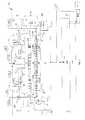
図1は、本発明の一実施形態にしたがった、半導体ウエハ処理装置を示している。装置は、上板100Aと、底板100Bと、壁100Cとによって形成されるチャンバ100を含む。一実施形態では、壁100Cは、切れ目のない円筒状の壁100Cを形成する。その他の実施形態では、壁100Cは、チャンバ100の内部空洞100Dがチャンバ100の外側の外部環境から隔離可能である限り、その他の構成を有することができる。チャンバの上板100Aと、底板100Bと、壁100Cとの間には、外部環境からのチャンバ100の内部空洞100Dの隔離を促すために、幾つかのシール139が配される。 FIG. 1 shows a semiconductor wafer processing apparatus according to an embodiment of the present invention. The apparatus includes a
様々な実施形態において、チャンバ100の上板100A、底板100B、及び壁100Cは、電気及び熱の優れた導体である金属であって、プロセスガス(それによりウエハ処理中に内部空洞100Dが暴露される)に化学的に適合可能な金属で形成することができる。例えば、様々な実施形態において、チャンバ100の構成要素を形成するために、アルミニウムやステンレス鋼などの金属が使用されてよい。また、シール139は、内部空洞100Dが暴露される処理材料に化学的に適合可能であってチャンバ100の外側の外部環境から内部空洞100Dを十分に隔離する限り、エラストマシール、又は消耗金属シール、又はその他の任意のタイプのシール材料であってよい。 In various embodiments, the
その他の実施形態では、チャンバ100の設置に特有な条件又はその他の検討事項を満足させられるように、上板100A、底板100B、及び壁100Cのうちの任意の1つ以上の外側に、1枚以上の追加の板又は部材を配することができる。また、上板100A、底板100B、及び/又は壁100Cは、具体的な実装形態に適するように、これらの追加の板又は部材に留め付けることができる。上板100A、底板100B、及び壁100Cを含むチャンバ100構造は、導電性材料で形成され、基準接地電位に電気的に接続される。 In other embodiments, one or more outside of any one or more of the
チャンバ100は、排出ポート135を含み、該ポート135は、内部空洞100D内からガス及び/又は微粒子を除去するために排出ポート135を通して負圧が印加可能であるように、外部の排出ポンプ137への内部空洞100Dの流体接続を提供する。一実施形態では、チャンバ100は、また、内部空洞100Dへのウエハ113の挿入及びそれに対応する内部空洞100Dからのウエハ113の取り出しを可能にするためにチャンバ壁100Cの一区画内に形成されたゲート弁102を含む。ゲート弁102は、その閉位置において、外部環境からの内部空洞100Dの隔離を維持するように定められる。様々な実施形態において、排出ポンプ137は、チャンバ100の内部空洞100Dから流体の流れを引き出すために排出ポート135において吸引を行うことができる限り、様々に異なる形で実装可能である。 The
チャンバ100の内部空洞100D内に、二重プラズマ処理装置が配される。二重プラズマ処理装置は、上方プラズマ発生空間103を含む上方プラズマチャンバ112を含む。二重プラズマ処理装置は、また、下方プラズマ発生空間109を含む下方プラズマチャンバ114を含む。上方プラズマチャンバ112/下方プラズマチャンバ114は、上方プラズマ発生空間103と下方プラズマ発生空間109とを分離するように配されたガス分配ユニット115によって物理的に及び流体的に接続される。 A double plasma processing apparatus is disposed in the
上方プラズマチャンバ112は、一部には、上方プラズマチャンバ112の周囲に定められて上板100Aに接続された外側構造部材104によって形成される。上方プラズマチャンバ112は、また、外側構造部材104内で上方プラズマ発生空間103の上方に配されたシャワーヘッド電極101を含む。シャワーヘッド電極101は、絶縁部材141によって上板100Aに留め付けられる。絶縁部材141は、電気的絶縁を提供するように定められる。しかしながら、絶縁部材141は、シャワーヘッド電極101と、絶縁部材141と境界を接するその他の構成要素との間で熱伝導を提供するようにも定められる。 The
動作中は、RF電源105からシャワーヘッド電極101に無線周波数(RF)電力が供給される。一実施形態では、RF電源105は、複数の周波数でRF電力を提供するように定められる。一実施形態では、RF電源105の周波数は、1kHzから100MHzまでの範囲内で設定される。別の一実施形態では、RF電源105の周波数は、400kHzから60MHzまでの範囲内で設定される。プラズマ密度は、主に、RF電源105によって制御される。 During operation, radio frequency (RF) power is supplied from the
また、一実施形態では、シャワーヘッド電極101は、上方プラズマ発生空間103内のプラズマ電位をプラズマ密度とは独立に制御することを可能にするために、DCバイアス源120に接続される。DCバイアス源120は、接地より上の様々な電圧設定にシャワーヘッド電極101のバイアスを制御するように定められる。一実施形態では、シャワーヘッド電極101のDCバイアス源120は、上方プラズマ発生空間103内のプラズマを下方プラズマ発生空間109内のプラズマに同期化させるためにパルス方式で動作するように定めることができる。より具体的には、DCバイアス源120のこのパルス式の制御は、上方プラズマ発生空間103内のプラズマと下方プラズマ発生空間109内のプラズマとの間の時間依存性の電圧差を制御するために使用することができる。 In one embodiment, the
絶縁部材141及び外側構造部材104の上方には、これら両方に接触してヒータ143が配される。ヒータ143は、上板100Aにも固定される。また、上板100A内には、幾本かの冷却流路145が定められる。上板100Aから熱を引き出すために、冷却流路145には、冷却流体が流される。一実施形態では、冷却流体は、水である。しかしながら、その他の実施形態は、上板100Aの材料に化学的に適合可能である限り、水以外の冷却流体を用いてもよい。一実施形態では、ヒータ143及び冷却流路145を通じて上板100Aの温度を制御するために、チャンバ100の様々な部分からの、熱電対によって測定された温度フィードバックが使用される。ヒータ143及び冷却流路145によって、シャワーヘッド電極101の、及びひいては上方プラズマ発生空間103の温度を制御することができる。 Above the insulating
シャワーヘッド電極101は、絶縁リング147によって外側構造部材104から電気的に絶縁されている。一実施形態では、絶縁リング147及び/又は絶縁部材141は、石英で形成される。その他の実施形態では、絶縁リング147及び/又は絶縁部材141は、熱伝導も提供しつつ電気的絶縁を提供する限り、石英以外の材料で形成することができる。 The
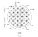
図2は、本発明の一実施形態にしたがった、シャワーヘッド電極101の底面図を示している。シャワーヘッド電極101は、プラズマプロセスガスを上方プラズマ発生空間103に供給するように定められたガス供給ポート121の配列を含む。プラズマプロセスガスは、1つ以上のプラズマプロセスガス供給源116からシャワーヘッド電極101に供給される。一部の実施形態では、ガス供給源116は、シャワーヘッド電極101を通って流れるものとして適したガス及び/又はガス混合の選択を提供する複数のガス供給部及び/又はガスボックスを表わしている。シャワーヘッド電極101は、上方プラズマ発生空間103への分配のために第1のプラズマプロセスガスがシャワーヘッド電極101を通ってガス供給ポート121の配列へ流れるのに伴って、該ガスにRF電力を供給するように定められる。FIG. 2 shows a bottom view of the
様々な実施形態において、シャワーヘッド電極101は、アルミニウムやステンレス鋼などのような、電気及び熱の優れた導体であって上方プラズマ発生空間103内で行われるプロセスに化学的に適合可能である金属で形成することができる。一実施形態では、上方プラズマ発生空間103内でプラズマに暴露されるシャワーヘッド電極101の部分は、耐プラズマ材料の覆いによって保護される。一実施形態では、耐プラズマ材料は、被覆として形成される。別の一実施形態では、耐プラズマ材料は、シャワーヘッド電極101を共形的に覆う例えば板などの保護構造として形成される。これらのいずれの実施形態でも、耐プラズマ材料は、耐プラズマ材料とシャワーヘッド電極101との間で適切な電気伝導及び熱伝導を保証するためにシャワーヘッド電極101に固定される。様々な実施形態において、シャワーヘッド電極101を保護するために使用される耐プラズマ被覆/覆いは、シリコン、シリコン炭化物、シリコン酸化物、イットリウム酸化物などで形成することができる。 In various embodiments, the
図2に示されるような一実施形態では、シャワーヘッド電極101のガス供給ポート121は、上方プラズマ発生空間103に面している複数の同心の放射状ゾーン101A、101B、101C内に配置される。各同心放射状ゾーン101A、101B、101C内のガス供給ポート121は、各同心放射状ゾーン101A、101B、101Cへのプラズマプロセスガスの供給が独立に制御可能であるように、それぞれのガス流量制御機器201A、201B、201Cに配管される。シャワーヘッド電極101の複数の同心放射状ゾーン101A、101B、101Cへのプラズマプロセスガス供給の独立制御は、中心から縁にかけてのプラズマ均一性の制御を向上させられることがわかる。図2の実施形態例は、3つの同心ガス供給ゾーン101A、101B、101Cを示しているが、シャワーヘッド電極101は、独立制御可能なガス供給ゾーンをより多数又はより少数含むように定められてもよいことがわかる。例えば、別の一実施形態では、シャワーヘッド電極101は、2つの独立に制御可能な同心ガス供給ゾーンを含むように定められる。 In one embodiment as shown in FIG. 2, the gas supply port 121 of the
前述のように、シャワーヘッド電極101は、上方プラズマ発生空間103の上表面を形成し、ガス分配ユニット115は、上方プラズマ発生空間103の下表面を形成する。一実施形態では、ガス分配ユニット115は、上方プラズマ発生空間103のための接地電極を提供する。一実施形態では、シャワーヘッド電極101及びガス分配ユニット115は、おおよそ1対1の電源対接地表面積を形成する。 As described above, the
シャワーヘッド電極101を伴う図1の実施形態では、上方プラズマチャンバ112は、容量結合プラズマチャンバである。この実施形態では、シャワーヘッド電極101の下表面とガス分配ユニット115の上表面との間で垂直に測定される、上方プラズマ発生空間103の垂直距離が、約1cmから約5cmの範囲内に設定される。一実施形態では、上方プラズマ発生空間103のこの垂直距離は、約2cmである。別の一実施形態では、シャワーヘッド電極101は、上方プラズマチャンバ112が誘導結合プラズマチャンバであるように、誘導コイルによって機能的に置き換えることができる。この実施形態では、上方プラズマ発生空間103の垂直距離は、最大で約12cmであってよい。 In the embodiment of FIG. 1 with the
下方プラズマチャンバ114は、一部には、下方プラズマチャンバ114の周囲に定められた外側構造部材106によって形成される。一実施形態では、下方プラズマチャンバ114の外側構造部材106は、下方プラズマチャンバ114の外側構造部材106が上方プラズマチャンバ112の外側構造部材104によって上板100Aから効果的にぶら下がるように、幾つかの構造的リンク部材によって上方プラズマチャンバ112の外側構造部材104に剛性接続される。この実施形態では、構造的リンク部材は、排出流路125を通って伸びることができるが、排出流路125内の流体の流れを不利に妨げることのないように定められる。 The
ガス分配ユニット115は、上方プラズマ発生空間103と下方プラズマ発生空間109との間に配される。ガス分配ユニット115は、その上表面が上方プラズマ発生空間103の下方境界を提供するように及びその下表面が下方プラズマ発生空間109の上方境界を提供するように上方プラズマ発生空間103を下方プラズマ発生空間109から分離するために形成された板として定められる。 The
ガス分配ユニット115は、下方プラズマチャンバ114の外側構造部材106によって固定位置に保持される。ガス分配ユニット115は、ガス供給ポート119の配列を通してプラズマプロセスガスを下方プラズマ発生空間109に供給するように定められる。ガス分配ユニット115は、更に、上方プラズマ発生空間103と下方プラズマ発生空間109との間で制御された流体連通を提供するために貫通穴117の配列を含むように定められる。各貫通穴117は、ガス分配ユニット115板を通ってその上表面から下表面へ伸びる。 The
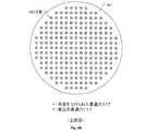
図3Aは、本発明の一実施形態にしたがった、ガス分配ユニット115の底面図を示している。ガス供給ポート119及び貫通穴117のそれぞれは、ガス分配ユニット115の下表面を通して開放流体連通するように定められる。ガス供給ポート119の配列は、貫通穴117の配列の間に散りばめられている。ガス供給ポート119は、ガス分配ユニット115内においてガス供給ポート119と貫通穴117との間で直接的な流体連通が存在しないように、ガス分配ユニット115を通して1つ以上のプラズマプロセスガス供給源118に配管されている。 FIG. 3A shows a bottom view of the
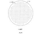
図3Bは、本発明の一実施形態にしたがった、ガス分配ユニット115の上面図を示している。各貫通穴117は、ガス分配ユニット115の上表面を通して開放流体連通するように定められる。しかしながら、ガス供給ポート119は、ガス分配ユニット115の上表面を通して流体的に暴露されてはいない。したがって、ガス供給ポート119は、プラズマプロセスガスを下方プラズマ発生空間109のみに流入させるように定められる。反対に、貫通穴117は、上方プラズマ発生空間103と下方プラズマ発生空間109との間で流体連通を可能にするように定められる。ガス分配ユニット115の貫通穴117を通した流体の流れは、主に、上方プラズマ発生空間103と下方プラズマ発生空間109との間の圧力差によって制御される。 FIG. 3B shows a top view of the
ガス分配ユニット115は、RF帰路電極、プラズマプロセスガスマニホールド、流体の流れを逸らせる邪魔板(バッフルプレート)、及びイオンフィルタとして機能することが理解される。様々な実施形態において、ガス分配ユニット115は、アルミニウム、ステンレス鋼、シリコン、シリコン炭化物、シリコン酸化物、イットリウム酸化物、又は暴露されるプラズマプロセスに適したプラズマ抵抗、電気伝導、及び熱伝導を提供する原則あらゆるその他の材料などの、電気及び熱の優れた導体であって、上方プラズマ発生空間103内及び下方プラズマ発生空間109内で行われるプロセスに化学的に適合可能である金属で形成することができる。 It is understood that the
様々な実施形態において、ガス分配ユニット115は、上方プラズマ発生空間103内で発生するイオンに作用させるのに適したバイアスを提供しつつRF電源105及び111のための適切な接地帰路も提供することを可能にするために、自身のDCバイアス源124及び/又はRF電源122に接続されている。RF電源122は、また、複数の周波数でRF電力を提供するように定められる。また、一実施形態では、上方プラズマ発生空間103内で発生するイオンに影響を及ぼすためのバイアス電圧を提供するために、ガス分配ユニット115に電極130が埋め込まれ、DCバイアス源124に接続されている。一実施形態では、埋め込み電極130に印加されるバイアス電圧が、貫通穴117を通過するイオンを加速させるか又は減速させるかのいずれかのために使用可能であるように、ガス分配ユニット115内の埋め込み電極130は、貫通穴117の周囲に定められる。また、一実施形態では、ガス分配ユニット115内の埋め込み電極130は、別々に制御可能な複数のゾーンに分かれて定められ、各ソーンは、自身のDCバイアス源124にそれぞれ接続される。この実施形態は、ガス分配ユニット115の領域ごとの独立したイオン制御を提供するために、ガス分配ユニット115の領域ごとの独立したバイアス印加を可能にする。 In various embodiments, the
一実施形態では、上方プラズマ発生空間103内又は下方プラズマ発生空間109内のいずれかのプラズマに暴露されるガス分配ユニット115の部分が、耐プラズマ材料の覆いによって保護される。一実施形態では、耐プラズマ材料は、被覆として形成される。別の一実施形態では、耐プラズマ材料は、ガス分配ユニット115を共形的に覆う例えば板などの保護構造として形成される。これらのいずれの実施形態でも、耐プラズマ材料は、耐プラズマ材料とガス分配ユニット115との間で適切な電気伝導及び熱伝導を保証するためにガス分配ユニット115に固定される。耐プラズマ保護構造の実施形態では、保護構造は、上方プラズマ発生空間103と下方プラズマ発生空間109との間の圧力差によって、又は幾つかの留め具によって、又はそれらの組み合わせによってガス分配ユニット115に固定することができる。様々な実施形態において、ガス分配ユニット115を保護するために使用される耐プラズマ被覆/保護構造は、シリコン、シリコン炭化物、シリコン酸化物、イットリウム酸化物、又は暴露されるプラズマプロセスに適したプラズマ抵抗、電気伝導、及び熱伝導を提供する原則あらゆるその他の材料で形成することができる。 In one embodiment, the portion of the
ガス分配ユニット115は、交換可能な構成要素として定められる。様々な配列のガス供給ポート119及び貫通穴117を有するように、様々なヴァージョン/構成のガス分配ユニット115を定めることができる。また、プラズマがガス分配ユニット115又はその機能性を損なう場合は、ガス分配ユニット115を取り換えることができる。 The
ガス供給ポート119及び貫通穴117は、それぞれ、不都合なプラズマの侵入を阻止しつつ、同時にまた、その中を通る流体の流れを最適にするように定められる。ガス供給ポート119及び貫通穴117のそれぞれを通る流体の流れ、並びにガス供給ポート119及び貫通穴117のそれぞれへのプラズマの侵入は、そのサイズに正比例する。したがって、ガス供給ポート119及び貫通穴117のそれぞれは、その中を通る流体の適切な流れを提供するのに十分な大きさをとどめつつ、不都合なプラズマの侵入を阻止するのに十分な小ささであるように、そのサイズを定める必要がある。様々な実施形態において、ガス供給ポート119の直径は、約0.1mmから約3mmに及ぶ範囲内の大きさである。様々な実施形態において、貫通穴117の直径は、約0.5mmから約5mmに及ぶ範囲内の大きさである。しかしながら、様々な実施形態において、ガス供給ポート119及び貫通穴117は、プラズマの侵入を適切に抑制しつつ、同時にまた、適切な流体の流れを提供する限り、基本あらゆる直径サイズにそれぞれ定められてよいことが理解される。 The
ガス供給ポート119への流体の流れの圧力が直接的に制御可能であるゆえに、ガス供給ポート119は、プラズマの侵入を基本的に阻止するのに十分な小さに定めることが可能である。しかしながら、ガス供給ポート119は、その中に超音速の流体の流れを生じさせるほどの小ささには定めないことが適切である。ガス供給ポート119からの超音速の流体の流れを回避するために、ガス供給ポート119は、ガス分配ユニット115の下表面からのその出口において拡散形状(ディフューザ形状)を有するように定めることができる。図3Cは、本発明の一実施形態にしたがった、ガス供給ポート119の断面図を示している。ガス供給ポート119は、ガス分配ユニット115からの出口場所において拡散形状307を有するように示されている。 Because the pressure of the fluid flow to the
ガス分配ユニット115は、ガス供給ポート119の配列に流体接続されたガス供給内部流路を含む。これらのガス供給内部流路は、1つ以上のプラズマプロセスガス供給源118に流体接続されている。ガス供給内部流路308及び関連のガス供給ポート119は、プラズマプロセスガスが下方プラズマ発生空間109には分配されるが上方プラズマ発生空間103には分配されないように、貫通穴117の配列の間に定められる。一実施形態では、上方プラズマ発生空間103及び下方プラズマ発生空間109へのプラズマプロセスガスの流量が独立に制御可能であるように、下方プラズマ発生空間109用のプラズマプロセスガス供給源118は、上方プラズマ発生空間103用のプラズマプロセスガス供給源116とは別である。一実施形態では、上方プラズマ発生空間103及び下方プラズマ発生空間109の両方用に、1つ以上の共用プラズマプロセスガス供給源を使用することができる。ただし、この実施形態では、各共用プラズマプロセスガス供給源からのプラズマプロセスガスの流れが、上方プラズマ発生空間103及び下方プラズマ発生空間109のそれぞれについて別々に制御される。また、一部の実施形態では、ガス供給源118は、ガス分配ユニット115を通って流れるものとして適したガス及び/又はガス混合の選択を提供する複数のガス供給部及び/又はガスボックスを表わすことが理解される。The
図3Aに示されるような一実施形態では、ガス分配ユニット115内のガス供給内部流路308は、それぞれの領域/ゾーンにおけるガス供給ポート119へのプラズマプロセスガスの流量が別々に制御可能であるように、ガス供給ポート119の配列をガス分配ユニット115の下表面全域にわたり複数の同心領域/ゾーン115A、115B、115Cに流体的に分離するように定められる。一実施形態では、各同心領域/ゾーン115A、115B、115Cへのプラズマプロセスガスの供給が独立に制御可能であるように、各同心領域/ゾーン115A、115B、115Cにおけるガス供給ポート119は、それぞれのガス流制御機器305A、305B、305Cに配管されている。In one embodiment as shown in FIG. 3A, the gas supply
独立に制御可能な複数の同心領域/ゾーン115A、115B、115Cへのガス供給ポート119の分離は、下方プラズマ発生空間109内における中心から縁にかけてのガス供給の制御を提供し、これは、ひいては、下方プラズマ発生空間109内における中心から縁にかけてのプラズマ均一性の制御を促進する。図3Aの実施形態例は、3つの同心ガス供給領域/ゾーン115A、115B、115Cを示しているが、ガス分配ユニット115は、独立に制御可能なガス供給領域/ゾーンをより多く又は少なく含むように定められてもよいことが理解される。例えば、別の一実施形態では、ガス分配ユニット115は、2つの独立に制御可能な同心ガス供給領域/ゾーンを含むように定められる。 Separation of
一実施形態では、貫通穴117の数は、上方プラズマ発生空間103から下方プラズマ発生空間109への適切なラジカル/中性の流れを提供するために、ガス供給ポート119の数を上回っている。また、貫通穴117は、上方プラズマ発生空間103から下方プラズマ発生空間109への適切なラジカル/中性の流れを提供するために、ガス供給ポート119よりも大きいサイズを有するように定めることができる。しかしながら、前述のように、貫通穴117のサイズは、上方プラズマ発生空間103及び下方プラズマ発生空間109のいずれからの貫通穴117への不都合なプラズマ侵入も阻止するように制限される。 In one embodiment, the number of through
一実施形態では、貫通穴117の一部又は全部は、一定の角度でガス分配ユニットを通って伸びるように定められる。図3Dは、本発明の一実施形態にしたがった、ガス分配ユニット115を通って伸びるように定められた貫通穴117の断面、及び角度303を示している。貫通穴117は、ガス分配ユニット115の上表面302からガス分配ユニット115の下表面304へ、ガス分配ユニット115の上表面302と下表面304との間で垂直に伸びる基準方向301からずれた角度303で伸びるように定められる。 In one embodiment, some or all of the through
上方プラズマ発生空間103内の荷電成分すなわちイオンが、貫通穴117を通って移動するのに伴って、電気的に接地されたガス分配ユニット115に遭遇し、ガス分配ユニット115を通り抜けるラジアル/中性フラックスから、貫通穴117によって除去される可能性を増加させるために、貫通穴117は、角度をつけられている。一実施形態では、角度303は、貫通穴117を通して基準方向301にガス分配ユニット115を見通す視線を遮るのに十分な大きさである。 As charged components or ions in the upper
一実施形態では、ガス分配ユニット115内の全ての貫通穴117は、上方プラズマ発生空間103内で発生したほとんどどのイオンもガス分配ユニット115を通り抜けて下方プラズマ発生空間109に到らないことを保証するために、角度をつけられている。この実施形態は、貫通穴117によって、基本的に純粋なラジカル/中性フラックスを下方プラズマ発生空間109に導入させる。別の一実施形態では、一部の貫通穴117が、基準方向301と一致して実質的に真っ直ぐに伸びるように定められたその他の貫通穴117と比べて角度をつけられている。この実施形態は、イオンの一部を、上方プラズマ発生空間103から下方プラズマ発生空間109へ流れるラジカル/中性フラックスと混合させる。この実施形態では、真っ直ぐな貫通穴117対角度をつけられた貫通穴117の数及び分布を、ラジカル/中性フラックス内で所望のイオン濃度が達成されるように定めることができる。 In one embodiment, all through
一実施形態では、どの貫通穴117が上方プラズマ発生空間103に開口するかを制御するために、ガス分配ユニット115の上表面上に流量制御板が配される。図4Aは、本発明の一実施形態にしたがった、ガス分配ユニット115の上表面302上に配された流量制御板401を示している。一実施形態では、流量制御板401は、約3mmから約6mmに及ぶ範囲内の厚さ403を有する円盤として定められる。流量制御板401円盤は、流量を制御されるべき貫通穴117を覆うのに十分な直径を有するように定められる。一実施形態では、流量制御板401の円盤は、ガス分配ユニット115によって提供されるRF帰路に対して上方プラズマ発生空間103内のプラズマが均一に暴露されることを維持するように、ガス分配ユニット115の上表面を覆う直径を有するように定められる。 In one embodiment, a flow control plate is disposed on the upper surface of the
一実施形態では、流量制御板401は、電気及び熱に対して伝導性の材料で形成され、流量制御板401とガス分配ユニット115との間で適切な電気伝導及び熱伝導を保証するためにガス分配ユニット115に固定される。一実施形態では、流量制御板401は、上方プラズマ発生空間103と下方プラズマ発生空間109との間の圧力差によって、幾つかの留め具によって、又はそれらの組み合わせによってガス分配ユニット115に固定することができる。また、様々な実施形態において、流量制御板401は、ガス分配ユニット115に関連して上述されたような耐プラズマ被覆によって覆って保護することができる。 In one embodiment, the
一実施形態では、流量制御板401を通る複数の穴パターンが定められる。流量制御板401内の複数の穴パターンのそれぞれは、ガス分配ユニット115内の異なる群の貫通穴117群と合致している。流量制御板401をガス分配ユニット115の上表面に対して或る特定の回転位置でガス分配ユニット115の上表面上に配することは、流量制御板401内の複数の穴パターンのうちの特定の一パターンをガス分配ユニット115内の対応する貫通穴117群と合致させることに相当する。流量制御板401を通って伸びる複数の穴パターンのそれぞれは、ガス分配ユニット115内の異なる数の又は異なる空間パターンの貫通穴117を暴露させるように定められる。したがって、流量制御板401を通る、及びしたがってガス分配ユニット115を通るラジカル/中性流は、ガス分配ユニット115の上表面に対して或る特定の回転位置で流量制御板401を設定することによって制御することができる。 In one embodiment, a plurality of hole patterns through the
一実施形態では、流量制御板401は、ガス分配ユニット115を基準方向301に真っ直ぐ通って伸びる貫通穴を遮断することによってガス分配ユニット115を通るイオンの流れを遮断することを可能にする穴パターンを含むように定められる。図4Bは、本発明の一実施形態にしたがった、流量制御板401の上面図であり、該板は、その中に定められた穴405パターンがその下のガス分配ユニット115内に定められた全ての貫通穴117を通る流れを可能にするように位置決めされている。図4Cは、本発明の一実施形態にしたがった、流量制御板401の上面図であり、該板は、その中に定められた穴405パターンがその下のガス分配ユニット115内に定められた角度をつけられた貫通穴117を通る流れのみを可能にするように位置決めされている。また、その他の実施形態では、流量制御板401内の複数の穴405パターンは、ガス分配ユニット115を通るラジカル/中性子の流れを異なる空間パターンで提供するように定められる。 In one embodiment, the
図4Dは、本発明の一実施形態にしたがった、複数の同心状の回転式流量制御板407A、407B、407Cによって定められた流量制御板アセンブリ401Aの上面図を示している。各同心状の回転式流量制御板407A、407B、407Cは、ガス分配ユニット115内のどの貫通穴117が開かれる又は閉じられるかについての中心から縁にかけての制御を提供するために、独立に設定することができる。具体的には、流量制御板アセンブリ401Aは、ガス分配ユニット115の上表面上に同心状に配された、中心円盤407Aと複数の同心リング407B/407Cとを含む。なお、図4Dの具体的構成は、例として提供されていることが理解される。その他の実施形態は、図4Dに示された以外の数の同心状の回転式流量制御板を含んでいてよい。FIG. 4D shows a top view of the flow
中心円盤407A及び複数の同心リング407B/407Cのそれぞれは、その中を通って伸びる複数の穴パターン405A/405B/405Cをそれぞれ含む。複数の穴パターン405A/405B/405Cのそれぞれは、中心円盤407A及び同心リング407B/407Cのそれぞれをガス分配ユニット115の上表面に対して或る特定の回転位置でガス分配ユニット115の上表面上に配することが、複数の穴パターン405A/405B/405Cのうちの特定の一パターンをガス分配ユニット115内の対応する貫通穴117群と合致させることに相当するように、ガス分配ユニット115内の異なる貫通穴117群と合致している。中心円盤407A及び同心リング407B/407Cを通って伸びる複数の穴パターン405A/405B/405Cのそれぞれは、ガス分配ユニット115内の異なる数の又は異なる空間パターンの貫通穴117を暴露させるように定められる。 Each of the
図1に戻り、下方プラズマ発生空間109の下方においてチャンバ100の内部空洞10D内にチャック107が配される。一実施形態では、チャック107は、チャンバ100の壁100Cから片持ちされている。一実施形態では、チャック107は、静電チャックであり、RF電力を下方プラズマ発生空間109に供給するための電極を提供する。チャック107は、基板113すなわちウエハ113を、下方プラズマ発生空間109に暴露させて保持するように定められる。一実施形態では、チャック107上においてチャック107上の基板113受け/保持区域の周囲にウエハエッジリング149が配される。様々な実施形態において、ウエハエッジリングは、石英又はシリコンで形成される。また、一実施形態では、ウエハエッジリング149の下に導体148が配され、ウエハエッジリング149を通じて駆動DCバイアスに接続される。チャック107は、また、基板113及び下方プラズマ発生空間109の温度制御を可能にできるように、冷却流路及び/又は加熱素子の構成を含むように定められる。 Returning to FIG. 1, the
チャック107は、矢印123によって示されるように、内部空洞100D内で垂直に移動するように定められる。このように、チャック107は、ゲート弁102を通して基板113を受け取る/提供するために下降させることができ、また、下方プラズマ発生空間109の下表面を形成するために上昇させることができる。また、チャック107及びガス分配ユニット115の両方に垂直に測定される、下方プラズマ発生空間109の垂直距離は、チャック107の垂直位置を制御することによって設定及び制御することができる。下方プラズマ発生空間109の垂直距離は、中心から縁にかけて十分なプラズマ均一性及び密度を達成するように設定することができ、また、ガス供給ポート119及び/又は貫通穴117からのガス噴流によってウエハ113上に染みが形成されることを回避するように設定することができる。様々な実施形態において、下方プラズマ発生空間109の垂直距離は、約1cmから約5cmに及ぶ範囲内に、又は約2cmから約3.6cmに及ぶ範囲内に設定することができる。
チャック107は、更に、チャック107が下方プラズマ発生空間109のための電極として機能するように、RF電源111から下方プラズマ発生空間109にRF電力を供給するように定められる。なお、下方プラズマチャンバのRF電源111は、上方プラズマチャンバのRF電源105とは別であって、独立している。したがって、上方プラズマ発生空間103及び下方プラズマ発生空間109に供給されるRF電力は、別々に尚且つ独立に制御することができる。一実施形態では、RF電源111は、複数の周波数でRF電力を提供するように定められる。例えば、RF電源111は、2MHz、27MHz、及び60MHzの周波数でRF電力を提供するように定めることができる。なお、上方プラズマチャンバ112及び下方プラズマチャンバ114のためのRF電源105及び111のそれぞれは、RF電力の供給を可能にするために自身の整合回路網を通してシャワーヘッド電極101及びチャック107にそれぞれ接続されることが理解される。前述のように、一実施形態では、ガス分配ユニット115は、上方プラズマ発生空間103及び下方プラズマ発生空間109の両方のための、RF電力帰路における基準接地電極として機能する。 The
上方プラズマチャンバは、上方プラズマ発生空間103内のガスを通らせてチャンバ100の内部空洞100D内へ排出させるための排出流路125を含むように定められる。排出流路125は、シャワーヘッド電極101の半径方向周縁の外側及びガス分配ユニット115の半径方向周縁の外側で上方プラズマ発生空間103を取り巻くように定められる。この構成では、排出流路125は、上方プラズマチャンバの外側構造部材104の下表面と、下方プラズマチャンバのガス分配ユニット115及び外側構造部材106の両方の上表面との間で半径方向に伸びている。 The upper plasma chamber is defined to include a
上方プラズマ発生空間103から排出流路125を通ってチャンバ100の内部空洞100Dに到る流体の流れ、すなわちガスの流れを絞り調整するために、圧力スロットルリング127が排出流路125内で移動するように定められる。一実施形態では、圧力スロットルリング127は、上方プラズマチャンバ112の外側構造部材104内に共形的に形成された陥凹領域内で垂直に移動するように定められる。この実施形態では、圧力スロットルリング127は、排出流路125の流路面積を小さくし、そうして上方プラズマ発生空間103からの流体の流れを絞り調整するために、被制御方式で下降されて排出流路125に入ることができる。一実施形態では、圧力スロットルリング127は、上方プラズマ発生空間103から排出流路125を通ってチャンバ100の内部空洞100Dに入る流れを完全に遮断することが可能であるように定められる。 The
図1に示されている圧力スロットルリング127は、その実装形態の代表的な一実施形態である。その他の実施形態では、圧力スロットルリング127は、排出流路125を通る流体の流れに対する制御を提供する限り、様々な形態で実装することができる。また、一実施形態では、上方プラズマ発生空間103内の圧力を測定するために、圧力計が配される。この実施形態では、この測定された上方プラズマ発生空間103内の圧力は、圧力スロットルリング127の位置を制御するためのフィードバック信号を生成するために使用され、該信号は、ひいては、上方プラズマ発生空間103内の圧力の能動的制御を提供する。 The
下方プラズマチャンバは、下方プラズマ発生空間109内のガスを通らせてチャンバ100の内部空洞100D内へ排出させるためのスロット付き排出流路129群を含むように定められる。スロット付き排出流路129群は、チャック107の半径方向周縁の外側及びガス分配ユニット115の半径方向周縁の外側で下方プラズマ発生空間109を取り巻くように定められる。図1に示されるように、一実施形態では、スロット付き排出流路129群は、基板112を上に保持しているチャック107の上表面に近い垂直位置に位置する下方プラズマチャンバ114の外側構造部材106の水平部分に定められている。この実施形態では、スロット付き排出流路129群は、下方プラズマチャンバ114の外側構造部材106の水平部分を垂直に通って伸びる。 The lower plasma chamber is defined to include a group of slotted
下方プラズマ発生空間109からスロット付き排出流路129群を通ってチャンバ100の内部空洞100Dに入る流体の流れ、すなわちガスの流れを絞り調整するために、圧力制御リング131がスロット付き排出流路129群に近づくように及びスロット付き排出流路129群から遠ざかるように定められる。一実施形態では、圧力制御リング131は、スロット付き排出流路129群に近づくように及びスロット付き排出流路129群から遠ざかるように垂直方向に移動可能である水平の環状円盤として定められる。圧力制御リング131は、スロット付き排出流路129群にあてがわれたときに、すなわちスロット付き排出流路129群を中に形成された外側構造部材106の水平部分の下表面にあてがわれたときに、スロット付き排出流路129群を(内部空洞100D側で)覆うように定められる。 In order to restrict the flow of fluid entering the
下方プラズマ発生空間109からスロット付き排出流路129群を通ってチャンバ100の内部空洞100Dに到る流体の流れは、スロット付き排出流路129群に近づく及びスロット付き排出流路129群から遠ざかる圧力制御リング131の垂直移動を通じて絞り調整する、すなわち制御することができる。一実施形態では、圧力制御リング131は、下方プラズマ発生空間109からスロット付き排出流路129群を通ってチャンバ100の内部空洞100Dに入る流れを完全に遮断することを可能にするように定められる。また、一実施形態では、下方プラズマ発生空間109内の圧力を測定するために、圧力計が配される。この実施形態では、この測定された下方プラズマ発生空間109内の圧力は、圧力制御リング131の位置を制御するためのフィードバック信号を生成するために使用され、該信号は、ひいては、下方プラズマ発生空間109内の圧力の能動的制御を提供する。 The flow of fluid from the lower
上方プラズマチャンバ112及び下方プラズマチャンバ114は、ともに、それぞれの閉じ込めプラズマを取り囲むことが理解される。閉じ込めプラズマは、プラズマ領域内の、すなわち上方プラズマ発生空間103内及び下方プラズマ発生空間109内の体積、圧力、及び流れを制御することによってその滞留時間を制御することができるという点で有利である。プラズマ滞留時間は、ラジカル/中性子形成の一因である解離プロセスに影響を及ぼす。上方プラズマ発生空間103及び下方プラズマ発生空間109は、小さくて、圧力及び温度を十分に制御される。 It will be appreciated that the
前述のように、上方プラズマチャンバ112及び下方プラズマチャンバ114は、それぞれ自身のRF電源/制御、圧力制御、温度制御、プラズマプロセスガス源/制御、及びガス流量制御を有する。様々な実施形態において、上方プラズマ処理空間103内の圧力は、約100ミリトールから約1トールに及ぶ範囲内で、又は約200ミリトールから約600ミリトールに及ぶ範囲内で制御することができる。様々な実施形態において、下方プラズマ処理空間109内の圧力は、約5ミリトールから約100ミリトールに及ぶ範囲内で、又は約10ミリトールから約30ミリトールに及ぶ範囲内で制御することができる。 As described above, the
図5は、本発明の一実施形態にしたがった、上方プラズマ501及び下方プラズマ503を伴う図1のチャンバ100を示している。上方プラズマ501からのプロセスガスは、矢印505によって示されるように、上方プラズマ発生空間103から排出流路125を通ってチャンバ100の内部空洞100D内へ排出される。下方プラズマ503からのプロセスガスは、矢印507によって示されるように、下方プラズマ発生空間109からスロット付き排出流路129群を通ってチャンバ100の内部空洞100D内へ排出される。プロセスガスは、矢印509によって示されるように、排出ポート135を通ってチャンバ100の内部空洞100Dから排出される。 FIG. 5 shows the
上方プラズマチャンバ112及び下方プラズマチャンバ114の独立制御は、ウエハ処理レシピに関して、具体的にはイオンフラックスに対するラジカル/中性フラックスの独立制御に関して広範囲な可能性を提供することが理解される。以下では、2つの代表的ウエハプロセスが提供される。しかしながら、本明細書で開示される代表的ウエハプロセスは、例として提供されるに過ぎず、本明細書で開示される二重プラズマ処理チャンバ100の使用に対していかなる制限も課さないことが理解される。 It will be appreciated that independent control of the
代表的な一実施形態では、チャンバ100は、高フッ素ラジカル/中性フラックスをウエハ処理用プラズマにおけるCxFy(C4F8、C4F6など)の低解離と併せて利用するウエハプロセスを実施するために使用される。この代表的な実施形態では、上方プラズマ発生空間103へのプラズマプロセスガスとして、ArとNF3との混合が供給される。上方プラズマ発生空間103は、高圧力及び高RF周波数(60MHz)で動作される。上方プラズマ発生空間103内で高フッ素ラジカル/中性フラックスが発生し、ガス分配ユニット115の貫通穴117を通って流れる。上方プラズマ処理空間103内で発生するイオンは、ガス分配ユニット115によってフィルタリングされる。In one exemplary embodiment, the
また、この代表的な実施形態では、下方プラズマ発生空間109へのプラズマプロセスガスとして、ArとCxFyとの混合が供給される。下方プラズマ発生空間109は、低圧力と、低から中のRF周波数(2MHz及び27MHz)とで動作される。下方プラズマ発生空間109の低RF周波数は、ウエハ113に暴露されるプラズマにおけるCxFyの低解離に相当する。なお、必要なフッ素ラジカル/中性フラックスを発生させるために上方プラズマ発生空間103内で必要とされる高電力は、もし下方プラズマ発生空間109に印加された場合は、CxFyの高解離を引き起こすだろうことがわかる。したがって、二重プラズマチャンバ100は、上記プロセスのパフォーマンスを可能にする。In this exemplary embodiment, a mixture of Ar and Cx Fy is supplied as a plasma process gas to the lower
別の代表的な実施形態では、チャンバ100は、低圧力空間における高密度Arプラズマを高圧力空間におけるCxFy(C4F8、C4F6など)の高解離と併せて利用するウエハプロセスを実施するために使用される。この代表的な実施形態では、上方プラズマ発生空間103へのプラズマプロセスガスとして、ArとCxFyとの混合が供給される。上方プラズマ発生空間103は、CxFyの高解離を生じさせるために、高圧力及び高RF周波数(60MHz)で動作される。上方プラズマチャンバ103内で発生する高解離CxFyは、ガス分配ユニット115の貫通穴117を通って流れる。上方プラズマ処理空間103内で発生するイオンは、ガス分配ユニット115によってフィルタリングされる。また、この代表的な実施形態では、下方プラズマ発生空間109へのプラズマプロセスガスとして、Arが供給される。下方プラズマ発生空間109は、高イオンフラックスの高密度Arプラズマを発生させるために、低圧力と、低から中のRF周波数(2MHz及び27MHz)とで動作される。In another exemplary embodiment, the
動作に関する一実施形態では、下方プラズマチャンバ114の圧力制御リング131が閉じられ、上方プラズマチャンバ112は、排出のみの構成をとるように設定される。この実施形態では、上方プラズマ発生空間103内でプラズマは発生しない。この実施形態では、プラズマプロセスガスは、ガス分配ユニット115のガス供給ポート119を通って下方プラズマ発生空間109に流れ込む。また、この実施形態では、プラズマプロセスガスは、下方プラズマ発生空間109からガス分配ユニット115の貫通穴117を通って上方プラズマ発生空間103に入り、次いで、排出流路125を出てチャンバ100の内部空洞100D内へ排出される。 In one embodiment of the operation, the
この動作に関する実施形態は、下方プラズマ発生空間109への及び下方プラズマ発生空間109からの軸方向へのプラズマプロセスガスの投入及び送出を提供する。この実施形態では、ガスが半径方向にではなく垂直方向に送出されるので、ウエハ113全域にわたり圧力均一性の正確な制御を実現することができる。半径方向への排出ガスの送出は、ウエハ113全域にわたり半径方向に圧力を分布させることがわかる。この実施形態は、また、例えばミリ秒未満の短いプラズマ滞留時間が必要とされる原子層蒸着又は原子層エッチングなどの低流量用途における滞留時間の正確な制御も可能にする。 Embodiments relating to this operation provide for the input and delivery of plasma process gas to and from the lower
二重プラズマチャンバ100は、イオンプラズマ発生/適用からラジカル/中性フラックス発生/適用を切り離すように定められることがわかる。また、一実施形態では、下方プラズマチャンバ114は、ウエハ113をプラズマに暴露させることなく上方プラズマチャンバ112からのラジカル/中性フラックスをウエハ113に適用することができるように、受動的、すなわち排出専用であることができる。 It can be seen that the
本発明は、幾つかの実施形態の観点から説明されてきたが、当業者ならば、先の明細書を読むこと及び図面を検討することによって、様々な代替、追加、置き換え、及び均等物を認識できることがわかる。したがって、本発明は、本発明の真の趣旨及び範囲に含まれるものとして、このようなあらゆる代替、追加、置き換え、及び均等物を含むことを意図される。 Although the present invention has been described in terms of several embodiments, those skilled in the art will recognize various alternatives, additions, substitutions, and equivalents by reading the foregoing specification and studying the drawings. It can be recognized. Accordingly, the present invention is intended to embrace all such alternatives, additions, substitutions and equivalents as fall within the true spirit and scope of the invention.
Claims (20)
Translated fromJapanese基板を保持するように構成された上表面を有する静電チャックと、
前記静電チャックの上方に離間して配置されたガス分配ユニットであって、前記ガス分配ユニットは、前記静電チャックの前記上表面に対して実質的に平行に向いた底表面を有し、前記静電チャックの前記上表面と前記ガス分配ユニットの前記底表面との間の空間は、下方プラズマ発生空間を形成し、前記ガス分配ユニットは、処理ガスを受けて前記下方プラズマ発生空間に分配し、前記ガス分配ユニットは、前記ガス分配ユニットの前記底表面から前記ガス分配ユニットの上表面へ伸びる貫通穴の配列を含む、ガス分配ユニットと、
前記ガス分配ユニットを取り巻いて、前記静電チャックの上方の離間した位置で前記ガス分配ユニットを支持するように構成された外側下方構造部材と、
前記ガス分配ユニットの上方に離間して位置し、前記ガス分配ユニットの前記上表面と実質的に平行に向いた底表面を有するシャワーヘッド電極であって、前記シャワーヘッド電極の前記底表面と前記ガス分配ユニットの前記上表面との間の空間は、上方プラズマ発生空間を形成する、シャワーヘッド電極と、
前記シャワーヘッド電極を取り巻いて、前記ガス分配ユニットの上方の離間した位置で前記シャワーヘッド電極を支持するように構成された外側上方構造部材と、
前記上方プラズマ発生空間の周囲から半径方向外向きに伸びるように構成された排出流路であって、前記上方プラズマ発生空間を取り巻いて、前記外側上方構造部材と前記外側下方構造部材との間に半径方向外向きに伸びるように構成された排出流路と、
制御された量の距離だけ前記排出流路に垂直に伸びるように、前記外側上方構造部材内に共形的に形成された陥凹領域内で垂直に移動するように構成されたスロットルリングと、
を備える、半導体ウエハ処理装置。A semiconductor wafer processing apparatus,
An electrostatic chuck having an upper surface configured to hold a substrate;
A gas distribution unit spaced apart above the electrostatic chuck, the gas distribution unit having a bottom surface oriented substantially parallel to the top surface of the electrostatic chuck; A space between the upper surface of the electrostatic chuck and the bottom surface of the gas distribution unit forms a lower plasma generation space, and the gas distribution unit receives a processing gas and distributes it to the lower plasma generation space. And the gas distribution unit includes an array of through holes extending from the bottom surface of the gas distribution unit to the top surface of the gas distribution unit;
An outer lower structural member configured to surround the gas distribution unit and to support the gas distribution unit at a spaced position above the electrostatic chuck;
A shower head electrode spaced apart above the gas distribution unit and having a bottom surface facing substantially parallel to the top surface of the gas distribution unit, the shower head electrode and the bottom surface of the shower head electrode A space between the upper surface of the gas distribution unit and a showerhead electrode forming an upper plasma generation space;
An outer upper structural member configured to surround the showerhead electrode and to support the showerhead electrode at a spaced position above the gas distribution unit;
A discharge passage configured to extend radially outward from the periphery of the upper plasma generation space, and surrounds the upper plasma generation space between the outer upper structural member and the outer lower structural member. A discharge channel configured to extend radially outward;
A throttle ring configured to move vertically within a recessed area formed conformally in the outer upper structural member so as to extend vertically to the discharge flow path by a controlled amount of distance;
A semiconductor wafer processing apparatus comprising:
前記排出流路は、前記スロットルリングの下方の位置を除いて、半径方向の範囲に沿って実質的に均一な垂直方向の高さを有するように構成されている、半導体ウエハ処理装置。The semiconductor wafer processing apparatus according to claim 1,
The semiconductor wafer processing apparatus, wherein the discharge channel is configured to have a substantially uniform vertical height along a radial range except for a position below the throttle ring.
前記シャワーヘッド電極の外側周縁を取り巻くように構成された第1の絶縁リングであって、前記外側上方構造部材内に形成された水平のスロット内に配置され、前記シャワーヘッド電極の垂直方向の高さの一部に沿って伸びるように構成され、前記シャワーヘッド電極の前記外側周縁に物理的に接触するように構成された第1の絶縁リングを備える、半導体ウエハ処理装置。The semiconductor wafer processing apparatus according to claim 1, further comprising:
A first insulating ring configured to surround an outer peripheral edge of the showerhead electrode, disposed in a horizontal slot formed in the outer upper structural member, wherein the vertical height of the showerhead electrode is A semiconductor wafer processing apparatus comprising: a first insulating ring configured to extend along a portion of the length and configured to physically contact the outer periphery of the showerhead electrode.
前記第1の絶縁リングは、前記シャワーヘッド電極の前記底表面から下向きに遠ざかって伸びるテーパ状の底表面を有する、半導体ウエハ処理装置。The semiconductor wafer processing apparatus according to claim 3,
The semiconductor wafer processing apparatus, wherein the first insulating ring has a tapered bottom surface extending downward from the bottom surface of the showerhead electrode.
前記シャワーヘッド電極の前記外側周縁を取り巻くように構成された第2の絶縁リングであって、前記第1の絶縁リングの上表面に配置され、前記シャワーヘッド電極の前記外側周縁と前記外側上方構造部材との間に位置し、前記第1の絶縁リングの上方に位置する前記シャワーヘッド電極の前記垂直方向の高さの残部に沿って伸びるように構成され、前記シャワーヘッド電極と前記外側上方構造部材の両方に接触するように配置された第2の絶縁リングを備える、半導体ウエハ処理装置。The semiconductor wafer processing apparatus according to claim 3, further comprising:
A second insulating ring configured to surround the outer peripheral edge of the showerhead electrode, and disposed on an upper surface of the first insulating ring, wherein the outer peripheral edge and the outer upper structure of the showerhead electrode The shower head electrode and the outer upper structure configured to extend along the remainder of the vertical height of the shower head electrode positioned between the members and above the first insulating ring. A semiconductor wafer processing apparatus comprising a second insulating ring arranged to contact both of the members.
前記貫通穴の配列の第1の部分は、前記ガス分配ユニットの前記上表面と前記底表面との間に垂直に伸びる基準方向に対して角度をつけた方向に沿って、前記ガス分配ユニットの前記底表面から前記ガス分配ユニットの前記上表面に伸びる、半導体ウエハ処理装置。The semiconductor wafer processing apparatus according to claim 1,
A first portion of the array of through-holes extends along the direction angled with respect to a reference direction that extends perpendicularly between the top surface and the bottom surface of the gas distribution unit. A semiconductor wafer processing apparatus extending from the bottom surface to the top surface of the gas distribution unit.
前記基準方向に対する前記貫通穴の配列の前記第1の部分の角度は、前記基準方向に沿って前記ガス分配ユニットを見通す視線を遮るのに十分な大きさである、半導体ウエハ処理装置。The semiconductor wafer processing apparatus according to claim 6,
The semiconductor wafer processing apparatus, wherein an angle of the first portion of the array of through holes with respect to the reference direction is large enough to block a line of sight through the gas distribution unit along the reference direction.
前記貫通穴の配列の第2の部分は、前記基準方向に沿って前記ガス分配ユニットの前記底表面から前記ガス分配ユニットの前記上表面に伸びる、半導体ウエハ処理装置。The semiconductor wafer processing apparatus according to claim 6,
The semiconductor wafer processing apparatus, wherein a second portion of the array of through holes extends from the bottom surface of the gas distribution unit to the upper surface of the gas distribution unit along the reference direction.
前記貫通穴の配列の前記第1の部分及び前記第2の部分は、前記ガス分配ユニットの全域にわたり実質的に均一に混在して分布する、半導体ウエハ処理装置。The semiconductor wafer processing apparatus according to claim 8,
The semiconductor wafer processing apparatus, wherein the first portion and the second portion of the array of the through holes are distributed substantially uniformly and mixed over the entire area of the gas distribution unit.
前記スロットルリングは、前記スロットルリングが前記排出流路の中に完全に下降すると前記排出流路を通る前記上方プラズマ発生空間からの流れを完全に遮断するように構成されている、半導体ウエハ処理装置。The semiconductor wafer processing apparatus according to claim 1,
The throttle ring is configured to completely block the flow from the upper plasma generation space passing through the discharge flow path when the throttle ring is completely lowered into the discharge flow path. .
前記外側下方構造部材は、前記静電チャックに剛性接続されている、半導体ウエハ処理装置。The semiconductor wafer processing apparatus according to claim 1,
The semiconductor wafer processing apparatus, wherein the outer lower structural member is rigidly connected to the electrostatic chuck.
前記外側下方構造部材は、上方水平部分、下方水平部分、及び、前記上方水平部分と前記下方水平部分との間に伸びる垂直部分を含み、
前記上方水平部分は、前記ガス分配ユニットの外側周縁に対して密閉され、
前記下方水平部分は、前記静電チャックの外側周縁に対して密閉され、
前記外側下方構造部材の前記上方水平部分、前記下方水平部分、及び前記垂直部分の各々は、前記下方水平部分を貫通して形成されたスロット付き排出流路群を除いて不透過性の障壁を形成し、
前記スロット付き排出流路群は、前記下方プラズマ発生空間から流出する流体流路を形成する、半導体ウエハ処理装置。The semiconductor wafer processing apparatus according to claim 11, comprising:
The outer lower structural member includes an upper horizontal portion, a lower horizontal portion, and a vertical portion extending between the upper horizontal portion and the lower horizontal portion,
The upper horizontal portion is sealed against the outer periphery of the gas distribution unit;
The lower horizontal portion is sealed against the outer periphery of the electrostatic chuck;
Each of the upper horizontal portion, the lower horizontal portion, and the vertical portion of the outer lower structural member has an impermeable barrier except for a slotted discharge channel group formed through the lower horizontal portion. Forming,
The slotted discharge flow path group forms a fluid flow path that flows out of the lower plasma generation space.
前記スロット付き排出流路群の下方に配された圧力制御リングであって、前記スロット付き排出流路群に近づいたり遠ざかったりするように垂直方向に被制御方式で移動可能な水平の固体環状円盤として構成された圧力制御リングを備える、半導体ウエハ処理装置。The semiconductor wafer processing apparatus according to claim 12, further comprising:
A horizontal solid circular disk, which is a pressure control ring arranged below the slotted discharge channel group and is movable in a controlled manner in a vertical direction so as to approach or move away from the slotted discharge channel group A semiconductor wafer processing apparatus comprising a pressure control ring configured as:
前記圧力制御リングは、前記圧力制御リングが前記外側下方構造部材の前記下方水平部分に接触するために十分に上昇すると前記スロット付き排出流路群を通る前記下方プラズマ発生空間からの流れを完全に遮断するように構成されている、半導体ウエハ処理装置。The semiconductor wafer processing apparatus according to claim 13,
The pressure control ring completely moves the flow from the lower plasma generation space through the slotted discharge channel group when the pressure control ring is sufficiently raised to contact the lower horizontal portion of the outer lower structural member. A semiconductor wafer processing apparatus configured to shut off.
基板を半導体ウエハ処理装置内の静電チャックの上表面に配置することであって、前記半導体ウエハ処理装置は、
前記静電チャックの上方に離間して配置されたガス分配ユニットであって、前記ガス分配ユニットは、前記静電チャックの前記上表面に対して実質的に平行に向いた底表面を有し、前記静電チャックの前記上表面と前記ガス分配ユニットの底表面との間の空間は、下方プラズマ発生空間を形成し、前記ガス分配ユニットは、処理ガスを受けて前記下方プラズマ発生空間に分配し、前記ガス分配ユニットは、前記ガス分配ユニットの前記底表面から前記ガス分配ユニットの上表面へ伸びる貫通穴の配列を含む、ガス分配ユニットと、
前記ガス分配ユニットを取り巻いて、前記静電チャックの上方の離間した位置で前記ガス分配ユニットを支持するように構成された外側下方構造部材と、
前記ガス分配ユニットの上方に離間して位置し、前記ガス分配ユニットの前記上表面に対して実質的に平行に向いた底表面を有するシャワーヘッド電極であって、前記シャワーヘッド電極の前記底表面と前記ガス分配ユニットの前記上表面との間の空間は、上方プラズマ発生空間を形成する、シャワーヘッド電極と、
前記シャワーヘッド電極を取り巻いて、前記ガス分配ユニットの上方の離間した位置で前記シャワーヘッド電極を支持するように構成された外側上方構造部材と、
前記上方プラズマ発生空間の周囲から半径方向外向きに伸びるように構成された排出流路であって、前記上方プラズマ発生空間を取り巻いて、前記外側上方構造部材と前記外側下方構造部材との間に半径方向外向きに伸びるように構成された排出流路と、
制御された量の距離だけ前記排出流路に垂直に伸びるように、前記外側上方構造部材内に共形的に形成された陥凹領域内で垂直に移動するように構成されたスロットルリングと、を備え、
前記方法は、更に、
前記基板を保持するために前記静電チャックを動作させることと、
第1の処理ガスを前記シャワーヘッド電極を通して前記上方プラズマ発生空間に流すことと、
前記第1の処理ガスを前記上方プラズマ発生空間内でプラズマ化するために無線周波数電力を前記シャワーヘッド電極に供給することであって、前記上方プラズマ発生空間内のプラズマの反応性成分は、前記ガス分配ユニット内の前記貫通穴の配列を通って前記下方プラズマ発生空間に流れ込む、ことと、
第2の処理ガスを前記ガス分配ユニットを通して前記下方プラズマ発生空間に流すことと、
前記第2の処理ガスを前記下方プラズマ発生空間内でプラズマ化するために無線周波数電力を前記静電チャックに供給することと、
を含む、方法。A method for processing a semiconductor wafer comprising:
Disposing a substrate on an upper surface of an electrostatic chuck in a semiconductor wafer processing apparatus, wherein the semiconductor wafer processing apparatus comprises:
A gas distribution unit spaced apart above the electrostatic chuck, the gas distribution unit having a bottom surface oriented substantially parallel to the top surface of the electrostatic chuck; A space between the upper surface of the electrostatic chuck and a bottom surface of the gas distribution unit forms a lower plasma generation space, and the gas distribution unit receives a processing gas and distributes it to the lower plasma generation space. The gas distribution unit includes an array of through holes extending from the bottom surface of the gas distribution unit to an upper surface of the gas distribution unit; and
An outer lower structural member configured to surround the gas distribution unit and to support the gas distribution unit at a spaced position above the electrostatic chuck;
A showerhead electrode spaced apart above the gas distribution unit and having a bottom surface facing substantially parallel to the top surface of the gas distribution unit, the bottom surface of the showerhead electrode A space between the upper surface of the gas distribution unit and a showerhead electrode forming an upper plasma generation space;
An outer upper structural member configured to surround the showerhead electrode and to support the showerhead electrode at a spaced position above the gas distribution unit;
A discharge passage configured to extend radially outward from the periphery of the upper plasma generation space, and surrounds the upper plasma generation space between the outer upper structural member and the outer lower structural member. A discharge channel configured to extend radially outward;
A throttle ring configured to move vertically within a recessed area formed conformally in the outer upper structural member so as to extend vertically to the discharge flow path by a controlled amount of distance; With
The method further comprises:
Operating the electrostatic chuck to hold the substrate;
Flowing a first process gas through the showerhead electrode into the upper plasma generation space;
Supplying radio frequency power to the showerhead electrode in order to turn the first process gas into plasma in the upper plasma generation space, wherein a reactive component of plasma in the upper plasma generation space is Flowing through the array of through holes in the gas distribution unit into the lower plasma generation space;
Flowing a second process gas through the gas distribution unit into the lower plasma generation space;
Supplying radio frequency power to the electrostatic chuck to plasmify the second process gas in the lower plasma generation space;
Including the method.
前記排出流路を通る前記下方プラズマ発生空間からの流量を制御するために、前記外側上方構造部材内に前記共形的に形成された陥凹領域内で前記スロットルリングの垂直位置を制御することを含む、方法。The method of claim 15, further comprising:
Controlling the vertical position of the throttle ring within the conformally formed recessed area in the outer upper structural member to control the flow rate from the lower plasma generation space through the discharge flow path. Including a method.
圧力計を動作させて前記上方プラズマ発生空間内の圧力を計測することと、
前記スロットルリングの前記垂直位置を制御するためのフィードバック信号を生成することと、
前記上方プラズマ発生空間内の前記圧力の能動的制御を提供するために、前記生成されたフィードバック信号を用いて前記スロットルリングの前記垂直位置を制御することと、
を含む、方法。The method of claim 16, further comprising:
Operating a pressure gauge to measure the pressure in the upper plasma generation space;
Generating a feedback signal for controlling the vertical position of the throttle ring;
Controlling the vertical position of the throttle ring using the generated feedback signal to provide active control of the pressure in the upper plasma generation space;
Including the method.
前記外側下方構造部材は、前記下方プラズマ発生空間から流出する流体流路を形成するスロット付き排出流路群を備え、
前記半導体ウエハ処理装置は、前記スロット付き排出流路群の下方に配された圧力制御リングを備え、
前記圧力制御リングは、前記スロット付き排出流路群に近づいたり遠ざかったりするように垂直方向に被制御方式で移動可能な水平の固体環状円盤として構成され、
前記方法は、更に、前記スロット付き排出流路群を通る前記下方プラズマ発生空間からの流量を制御するために、前記圧力制御リングの垂直位置を制御することを含む、方法。16. A method according to claim 15, comprising
The outer lower structural member includes a slotted discharge channel group that forms a fluid channel that flows out of the lower plasma generation space,
The semiconductor wafer processing apparatus includes a pressure control ring disposed below the slotted discharge channel group,
The pressure control ring is configured as a horizontal solid annular disk movable in a controlled manner in a vertical direction so as to approach or move away from the slotted discharge flow path group,
The method further includes controlling a vertical position of the pressure control ring to control a flow rate from the lower plasma generation space through the slotted exhaust flow group.
前記上方プラズマ発生空間からの排出が、前記ガス分配ユニット内の前記貫通穴の配列、前記下方プラズマ発生空間、及び前記スロット付き排出流路群を通って前記圧力制御リングを過ぎて流れるように、前記スロットルリングを前記排出流路内で完全に下降させて前記排出流路を通る前記上方プラズマ発生空間からの流れを遮断することを含む、方法。The method of claim 18, further comprising:
So that the discharge from the upper plasma generation space flows past the pressure control ring through the array of through holes in the gas distribution unit, the lower plasma generation space, and the slotted discharge channel group, Lowering the throttle ring completely within the exhaust flow path to block flow from the upper plasma generation space through the exhaust flow path.
前記下方プラズマ発生空間からの排出が、前記ガス分配ユニット内の前記貫通穴の配列、前記上方プラズマ発生空間、及び前記排出流路を通って前記スロットルリングを過ぎて流れるように、前記外側下方構造部材に接触するように前記圧力制御リングを完全に上昇させて前記スロット付き排出流路群を通る前記下方プラズマ発生空間からの流れを遮断することを含む、方法。The method of claim 18, further comprising:
The outer lower structure such that discharge from the lower plasma generation space flows past the throttle ring through the array of through holes in the gas distribution unit, the upper plasma generation space, and the discharge flow path. Raising the pressure control ring completely to contact a member to block flow from the lower plasma generation space through the slotted discharge channels.
Applications Claiming Priority (2)
| Application Number | Priority Date | Filing Date | Title |
|---|---|---|---|
| US12/850,559US9184028B2 (en) | 2010-08-04 | 2010-08-04 | Dual plasma volume processing apparatus for neutral/ion flux control |
| US12/850,559 | 2010-08-04 |
Related Parent Applications (1)
| Application Number | Title | Priority Date | Filing Date |
|---|---|---|---|
| JP2013523167ADivisionJP5913312B2 (en) | 2010-08-04 | 2011-06-22 | Semiconductor wafer processing apparatus, semiconductor wafer processing system, and gas distribution unit for neutral / ion flux control |
Publications (2)
| Publication Number | Publication Date |
|---|---|
| JP2016167606A JP2016167606A (en) | 2016-09-15 |
| JP6110540B2true JP6110540B2 (en) | 2017-04-05 |
Family
ID=45555213
Family Applications (2)
| Application Number | Title | Priority Date | Filing Date |
|---|---|---|---|
| JP2013523167AActiveJP5913312B2 (en) | 2010-08-04 | 2011-06-22 | Semiconductor wafer processing apparatus, semiconductor wafer processing system, and gas distribution unit for neutral / ion flux control |
| JP2016074072AActiveJP6110540B2 (en) | 2010-08-04 | 2016-04-01 | Semiconductor wafer processing apparatus and method for processing semiconductor wafer |
Family Applications Before (1)
| Application Number | Title | Priority Date | Filing Date |
|---|---|---|---|
| JP2013523167AActiveJP5913312B2 (en) | 2010-08-04 | 2011-06-22 | Semiconductor wafer processing apparatus, semiconductor wafer processing system, and gas distribution unit for neutral / ion flux control |
Country Status (7)
| Country | Link |
|---|---|
| US (2) | US9184028B2 (en) |
| JP (2) | JP5913312B2 (en) |
| KR (2) | KR101911562B1 (en) |
| CN (2) | CN103053011B (en) |
| SG (2) | SG10201505975QA (en) |
| TW (1) | TWI605495B (en) |
| WO (1) | WO2012018449A2 (en) |
Cited By (1)
| Publication number | Priority date | Publication date | Assignee | Title |
|---|---|---|---|---|
| US10811381B2 (en) | 2018-08-03 | 2020-10-20 | Samsung Electronics Co., Ltd. | Wafer to wafer bonding method and wafer to wafer bonding system |
Families Citing this family (236)
| Publication number | Priority date | Publication date | Assignee | Title |
|---|---|---|---|---|
| US9493875B2 (en)* | 2008-09-30 | 2016-11-15 | Eugene Technology Co., Ltd. | Shower head unit and chemical vapor deposition apparatus |
| FI124414B (en)* | 2010-04-30 | 2014-08-29 | Beneq Oy | Outlets and apparatus for processing substrates |
| US9324576B2 (en) | 2010-05-27 | 2016-04-26 | Applied Materials, Inc. | Selective etch for silicon films |
| US9793126B2 (en) | 2010-08-04 | 2017-10-17 | Lam Research Corporation | Ion to neutral control for wafer processing with dual plasma source reactor |
| US9184028B2 (en) | 2010-08-04 | 2015-11-10 | Lam Research Corporation | Dual plasma volume processing apparatus for neutral/ion flux control |
| US8869742B2 (en)* | 2010-08-04 | 2014-10-28 | Lam Research Corporation | Plasma processing chamber with dual axial gas injection and exhaust |
| US20130059448A1 (en)* | 2011-09-07 | 2013-03-07 | Lam Research Corporation | Pulsed Plasma Chamber in Dual Chamber Configuration |
| US20120052216A1 (en)* | 2010-08-27 | 2012-03-01 | Applied Materials, Inc. | Gas distribution showerhead with high emissivity surface |
| US10283321B2 (en) | 2011-01-18 | 2019-05-07 | Applied Materials, Inc. | Semiconductor processing system and methods using capacitively coupled plasma |
| US8771539B2 (en) | 2011-02-22 | 2014-07-08 | Applied Materials, Inc. | Remotely-excited fluorine and water vapor etch |
| JP5661513B2 (en)* | 2011-03-03 | 2015-01-28 | 東京エレクトロン株式会社 | Plasma processing equipment |
| KR101937115B1 (en) | 2011-03-04 | 2019-01-09 | 노벨러스 시스템즈, 인코포레이티드 | Hybrid ceramic showerhead |
| US8999856B2 (en) | 2011-03-14 | 2015-04-07 | Applied Materials, Inc. | Methods for etch of sin films |
| US9064815B2 (en)* | 2011-03-14 | 2015-06-23 | Applied Materials, Inc. | Methods for etch of metal and metal-oxide films |
| KR101241049B1 (en) | 2011-08-01 | 2013-03-15 | 주식회사 플라즈마트 | Plasma generation apparatus and plasma generation method |
| US8771536B2 (en) | 2011-08-01 | 2014-07-08 | Applied Materials, Inc. | Dry-etch for silicon-and-carbon-containing films |
| US8679982B2 (en) | 2011-08-26 | 2014-03-25 | Applied Materials, Inc. | Selective suppression of dry-etch rate of materials containing both silicon and oxygen |
| US8679983B2 (en) | 2011-09-01 | 2014-03-25 | Applied Materials, Inc. | Selective suppression of dry-etch rate of materials containing both silicon and nitrogen |
| US9039911B2 (en) | 2012-08-27 | 2015-05-26 | Lam Research Corporation | Plasma-enhanced etching in an augmented plasma processing system |
| US8927390B2 (en) | 2011-09-26 | 2015-01-06 | Applied Materials, Inc. | Intrench profile |
| US8808563B2 (en) | 2011-10-07 | 2014-08-19 | Applied Materials, Inc. | Selective etch of silicon by way of metastable hydrogen termination |
| KR101246191B1 (en)* | 2011-10-13 | 2013-03-21 | 주식회사 윈텔 | Plasma generation apparatus and substrate processing apparatus |
| WO2013070436A1 (en) | 2011-11-08 | 2013-05-16 | Applied Materials, Inc. | Methods of reducing substrate dislocation during gapfill processing |
| KR101971312B1 (en)* | 2011-11-23 | 2019-04-22 | 램 리써치 코포레이션 | Multi zone gas injection upper electrode system |
| KR101504532B1 (en)* | 2012-03-09 | 2015-03-24 | 주식회사 윈텔 | Plasma Processing Method And Substrate Prosessing Apparatus |
| KR101332337B1 (en) | 2012-06-29 | 2013-11-22 | 태원전기산업 (주) | Microwave lighting lamp apparatus |
| US9267739B2 (en) | 2012-07-18 | 2016-02-23 | Applied Materials, Inc. | Pedestal with multi-zone temperature control and multiple purge capabilities |
| US9447365B2 (en)* | 2012-07-27 | 2016-09-20 | Applied Materials, Inc. | Enhanced cleaning process of chamber used plasma spray coating without damaging coating |
| US9373517B2 (en)* | 2012-08-02 | 2016-06-21 | Applied Materials, Inc. | Semiconductor processing with DC assisted RF power for improved control |
| TWI467625B (en)* | 2012-08-30 | 2015-01-01 | Univ Chang Gung | The plasma processing device |
| US9034770B2 (en) | 2012-09-17 | 2015-05-19 | Applied Materials, Inc. | Differential silicon oxide etch |
| US9023734B2 (en) | 2012-09-18 | 2015-05-05 | Applied Materials, Inc. | Radical-component oxide etch |
| US9390937B2 (en) | 2012-09-20 | 2016-07-12 | Applied Materials, Inc. | Silicon-carbon-nitride selective etch |
| US9132436B2 (en) | 2012-09-21 | 2015-09-15 | Applied Materials, Inc. | Chemical control features in wafer process equipment |
| JP6002522B2 (en)* | 2012-09-27 | 2016-10-05 | 株式会社Screenホールディングス | Thin film forming apparatus and thin film forming method |
| US8765574B2 (en) | 2012-11-09 | 2014-07-01 | Applied Materials, Inc. | Dry etch process |
| US8969212B2 (en) | 2012-11-20 | 2015-03-03 | Applied Materials, Inc. | Dry-etch selectivity |
| US9064816B2 (en) | 2012-11-30 | 2015-06-23 | Applied Materials, Inc. | Dry-etch for selective oxidation removal |
| US8980763B2 (en) | 2012-11-30 | 2015-03-17 | Applied Materials, Inc. | Dry-etch for selective tungsten removal |
| US20140166618A1 (en)* | 2012-12-14 | 2014-06-19 | The Penn State Research Foundation | Ultra-high speed anisotropic reactive ion etching |
| US9111877B2 (en) | 2012-12-18 | 2015-08-18 | Applied Materials, Inc. | Non-local plasma oxide etch |
| US8921234B2 (en) | 2012-12-21 | 2014-12-30 | Applied Materials, Inc. | Selective titanium nitride etching |
| US10256079B2 (en) | 2013-02-08 | 2019-04-09 | Applied Materials, Inc. | Semiconductor processing systems having multiple plasma configurations |
| US9362130B2 (en) | 2013-03-01 | 2016-06-07 | Applied Materials, Inc. | Enhanced etching processes using remote plasma sources |
| US9040422B2 (en) | 2013-03-05 | 2015-05-26 | Applied Materials, Inc. | Selective titanium nitride removal |
| US8801952B1 (en) | 2013-03-07 | 2014-08-12 | Applied Materials, Inc. | Conformal oxide dry etch |
| KR20210003959A (en)* | 2013-03-15 | 2021-01-12 | 어플라이드 머티어리얼스, 인코포레이티드 | Chamber design for semiconductor processing |
| US20140271097A1 (en) | 2013-03-15 | 2014-09-18 | Applied Materials, Inc. | Processing systems and methods for halide scavenging |
| KR101451244B1 (en)* | 2013-03-22 | 2014-10-15 | 참엔지니어링(주) | Liner assembly and substrate processing apparatus having the same |
| US9245761B2 (en) | 2013-04-05 | 2016-01-26 | Lam Research Corporation | Internal plasma grid for semiconductor fabrication |
| US9230819B2 (en) | 2013-04-05 | 2016-01-05 | Lam Research Corporation | Internal plasma grid applications for semiconductor fabrication in context of ion-ion plasma processing |
| CN103227091B (en)* | 2013-04-19 | 2016-01-27 | 中微半导体设备(上海)有限公司 | Plasma processing apparatus |
| US20140315392A1 (en)* | 2013-04-22 | 2014-10-23 | Lam Research Corporation | Cold spray barrier coated component of a plasma processing chamber and method of manufacture thereof |
| US8895449B1 (en) | 2013-05-16 | 2014-11-25 | Applied Materials, Inc. | Delicate dry clean |
| US9114438B2 (en) | 2013-05-21 | 2015-08-25 | Applied Materials, Inc. | Copper residue chamber clean |
| US9490149B2 (en)* | 2013-07-03 | 2016-11-08 | Lam Research Corporation | Chemical deposition apparatus having conductance control |
| US9017526B2 (en) | 2013-07-08 | 2015-04-28 | Lam Research Corporation | Ion beam etching system |
| US9147581B2 (en) | 2013-07-11 | 2015-09-29 | Lam Research Corporation | Dual chamber plasma etcher with ion accelerator |
| US9493879B2 (en) | 2013-07-12 | 2016-11-15 | Applied Materials, Inc. | Selective sputtering for pattern transfer |
| US9018111B2 (en)* | 2013-07-22 | 2015-04-28 | Asm Ip Holding B.V. | Semiconductor reaction chamber with plasma capabilities |
| US9773648B2 (en) | 2013-08-30 | 2017-09-26 | Applied Materials, Inc. | Dual discharge modes operation for remote plasma |
| US8956980B1 (en) | 2013-09-16 | 2015-02-17 | Applied Materials, Inc. | Selective etch of silicon nitride |
| US8951429B1 (en) | 2013-10-29 | 2015-02-10 | Applied Materials, Inc. | Tungsten oxide processing |
| US9576809B2 (en) | 2013-11-04 | 2017-02-21 | Applied Materials, Inc. | Etch suppression with germanium |
| US9236265B2 (en) | 2013-11-04 | 2016-01-12 | Applied Materials, Inc. | Silicon germanium processing |
| US9520303B2 (en) | 2013-11-12 | 2016-12-13 | Applied Materials, Inc. | Aluminum selective etch |
| US9245762B2 (en) | 2013-12-02 | 2016-01-26 | Applied Materials, Inc. | Procedure for etch rate consistency |
| US9117855B2 (en) | 2013-12-04 | 2015-08-25 | Applied Materials, Inc. | Polarity control for remote plasma |
| US9263278B2 (en) | 2013-12-17 | 2016-02-16 | Applied Materials, Inc. | Dopant etch selectivity control |
| US9287095B2 (en) | 2013-12-17 | 2016-03-15 | Applied Materials, Inc. | Semiconductor system assemblies and methods of operation |
| US9190293B2 (en) | 2013-12-18 | 2015-11-17 | Applied Materials, Inc. | Even tungsten etch for high aspect ratio trenches |
| US9287134B2 (en) | 2014-01-17 | 2016-03-15 | Applied Materials, Inc. | Titanium oxide etch |
| US9293568B2 (en) | 2014-01-27 | 2016-03-22 | Applied Materials, Inc. | Method of fin patterning |
| US9396989B2 (en) | 2014-01-27 | 2016-07-19 | Applied Materials, Inc. | Air gaps between copper lines |
| US9385028B2 (en) | 2014-02-03 | 2016-07-05 | Applied Materials, Inc. | Air gap process |
| US9499898B2 (en) | 2014-03-03 | 2016-11-22 | Applied Materials, Inc. | Layered thin film heater and method of fabrication |
| US9299575B2 (en) | 2014-03-17 | 2016-03-29 | Applied Materials, Inc. | Gas-phase tungsten etch |
| US9299537B2 (en) | 2014-03-20 | 2016-03-29 | Applied Materials, Inc. | Radial waveguide systems and methods for post-match control of microwaves |
| US9299538B2 (en) | 2014-03-20 | 2016-03-29 | Applied Materials, Inc. | Radial waveguide systems and methods for post-match control of microwaves |
| US9136273B1 (en) | 2014-03-21 | 2015-09-15 | Applied Materials, Inc. | Flash gate air gap |
| US9903020B2 (en) | 2014-03-31 | 2018-02-27 | Applied Materials, Inc. | Generation of compact alumina passivation layers on aluminum plasma equipment components |
| US9269590B2 (en) | 2014-04-07 | 2016-02-23 | Applied Materials, Inc. | Spacer formation |
| US9309598B2 (en) | 2014-05-28 | 2016-04-12 | Applied Materials, Inc. | Oxide and metal removal |
| US9847289B2 (en) | 2014-05-30 | 2017-12-19 | Applied Materials, Inc. | Protective via cap for improved interconnect performance |
| US10077497B2 (en)* | 2014-05-30 | 2018-09-18 | Lam Research Corporation | Hollow cathode discharge (HCD) suppressing capacitively coupled plasma electrode and gas distribution faceplate |
| US9378969B2 (en) | 2014-06-19 | 2016-06-28 | Applied Materials, Inc. | Low temperature gas-phase carbon removal |
| US9406523B2 (en) | 2014-06-19 | 2016-08-02 | Applied Materials, Inc. | Highly selective doped oxide removal method |
| US9425058B2 (en) | 2014-07-24 | 2016-08-23 | Applied Materials, Inc. | Simplified litho-etch-litho-etch process |
| US9159606B1 (en) | 2014-07-31 | 2015-10-13 | Applied Materials, Inc. | Metal air gap |
| US9496167B2 (en) | 2014-07-31 | 2016-11-15 | Applied Materials, Inc. | Integrated bit-line airgap formation and gate stack post clean |
| US9378978B2 (en) | 2014-07-31 | 2016-06-28 | Applied Materials, Inc. | Integrated oxide recess and floating gate fin trimming |
| US9165786B1 (en) | 2014-08-05 | 2015-10-20 | Applied Materials, Inc. | Integrated oxide and nitride recess for better channel contact in 3D architectures |
| US9659753B2 (en) | 2014-08-07 | 2017-05-23 | Applied Materials, Inc. | Grooved insulator to reduce leakage current |
| US9553102B2 (en) | 2014-08-19 | 2017-01-24 | Applied Materials, Inc. | Tungsten separation |
| CN105448635B (en)* | 2014-08-28 | 2018-01-09 | 北京北方华创微电子装备有限公司 | Atomic layer etching device and use its atomic layer lithographic method |
| US9355856B2 (en) | 2014-09-12 | 2016-05-31 | Applied Materials, Inc. | V trench dry etch |
| US9368364B2 (en) | 2014-09-24 | 2016-06-14 | Applied Materials, Inc. | Silicon etch process with tunable selectivity to SiO2 and other materials |
| US9355862B2 (en) | 2014-09-24 | 2016-05-31 | Applied Materials, Inc. | Fluorine-based hardmask removal |
| US9613822B2 (en) | 2014-09-25 | 2017-04-04 | Applied Materials, Inc. | Oxide etch selectivity enhancement |
| JP2016081945A (en)* | 2014-10-09 | 2016-05-16 | 株式会社ニューフレアテクノロジー | Vapor growth apparatus and vapor growth method |
| US9966240B2 (en) | 2014-10-14 | 2018-05-08 | Applied Materials, Inc. | Systems and methods for internal surface conditioning assessment in plasma processing equipment |
| US9355922B2 (en) | 2014-10-14 | 2016-05-31 | Applied Materials, Inc. | Systems and methods for internal surface conditioning in plasma processing equipment |
| US11637002B2 (en) | 2014-11-26 | 2023-04-25 | Applied Materials, Inc. | Methods and systems to enhance process uniformity |
| US9299583B1 (en) | 2014-12-05 | 2016-03-29 | Applied Materials, Inc. | Aluminum oxide selective etch |
| US10224210B2 (en)* | 2014-12-09 | 2019-03-05 | Applied Materials, Inc. | Plasma processing system with direct outlet toroidal plasma source |
| US10573496B2 (en) | 2014-12-09 | 2020-02-25 | Applied Materials, Inc. | Direct outlet toroidal plasma source |
| US9502258B2 (en) | 2014-12-23 | 2016-11-22 | Applied Materials, Inc. | Anisotropic gap etch |
| US9343272B1 (en) | 2015-01-08 | 2016-05-17 | Applied Materials, Inc. | Self-aligned process |
| US11257693B2 (en) | 2015-01-09 | 2022-02-22 | Applied Materials, Inc. | Methods and systems to improve pedestal temperature control |
| US9373522B1 (en) | 2015-01-22 | 2016-06-21 | Applied Mateials, Inc. | Titanium nitride removal |
| JP6600990B2 (en)* | 2015-01-27 | 2019-11-06 | 東京エレクトロン株式会社 | Plasma processing equipment |
| US9449846B2 (en) | 2015-01-28 | 2016-09-20 | Applied Materials, Inc. | Vertical gate separation |
| US9793104B2 (en) | 2015-01-29 | 2017-10-17 | Aixtron Se | Preparing a semiconductor surface for epitaxial deposition |
| US9728437B2 (en) | 2015-02-03 | 2017-08-08 | Applied Materials, Inc. | High temperature chuck for plasma processing systems |
| US20160225652A1 (en) | 2015-02-03 | 2016-08-04 | Applied Materials, Inc. | Low temperature chuck for plasma processing systems |
| US20210343509A9 (en)* | 2015-02-11 | 2021-11-04 | Applied Materials, Inc. | Conditioned semiconductor system parts |
| US9881805B2 (en) | 2015-03-02 | 2018-01-30 | Applied Materials, Inc. | Silicon selective removal |
| US10049862B2 (en)* | 2015-04-17 | 2018-08-14 | Lam Research Corporation | Chamber with vertical support stem for symmetric conductance and RF delivery |
| US10023959B2 (en) | 2015-05-26 | 2018-07-17 | Lam Research Corporation | Anti-transient showerhead |
| CN107835868B (en)* | 2015-06-17 | 2020-04-10 | 应用材料公司 | Gas control in a processing chamber |
| JP6483259B2 (en)* | 2015-06-29 | 2019-03-13 | 株式会社アルバック | Substrate processing equipment |
| US9793097B2 (en)* | 2015-07-27 | 2017-10-17 | Lam Research Corporation | Time varying segmented pressure control |
| US9741593B2 (en) | 2015-08-06 | 2017-08-22 | Applied Materials, Inc. | Thermal management systems and methods for wafer processing systems |
| US9691645B2 (en) | 2015-08-06 | 2017-06-27 | Applied Materials, Inc. | Bolted wafer chuck thermal management systems and methods for wafer processing systems |
| US9349605B1 (en)* | 2015-08-07 | 2016-05-24 | Applied Materials, Inc. | Oxide etch selectivity systems and methods |
| US10504700B2 (en) | 2015-08-27 | 2019-12-10 | Applied Materials, Inc. | Plasma etching systems and methods with secondary plasma injection |
| US11004661B2 (en)* | 2015-09-04 | 2021-05-11 | Applied Materials, Inc. | Process chamber for cyclic and selective material removal and etching |
| KR102340973B1 (en) | 2015-09-18 | 2021-12-17 | 삼성전자주식회사 | Device and method for semiconductor test and data analyze device |
| JP6784530B2 (en)* | 2016-03-29 | 2020-11-11 | 東京エレクトロン株式会社 | How to process the object to be processed |
| US10622189B2 (en)* | 2016-05-11 | 2020-04-14 | Lam Research Corporation | Adjustable side gas plenum for edge rate control in a downstream reactor |
| US10504754B2 (en) | 2016-05-19 | 2019-12-10 | Applied Materials, Inc. | Systems and methods for improved semiconductor etching and component protection |
| US10522371B2 (en) | 2016-05-19 | 2019-12-31 | Applied Materials, Inc. | Systems and methods for improved semiconductor etching and component protection |
| US9865484B1 (en) | 2016-06-29 | 2018-01-09 | Applied Materials, Inc. | Selective etch using material modification and RF pulsing |
| DE102016008775A1 (en) | 2016-07-22 | 2018-01-25 | Oliver Feddersen-Clausen | Coating device, in particular for Radical Enhanced Atomic Layer Deposition |
| JP6994502B2 (en)* | 2016-08-26 | 2022-01-14 | アプライド マテリアルズ インコーポレイテッド | Plasma screen for plasma processing chamber |
| US10629473B2 (en) | 2016-09-09 | 2020-04-21 | Applied Materials, Inc. | Footing removal for nitride spacer |
| US10062575B2 (en) | 2016-09-09 | 2018-08-28 | Applied Materials, Inc. | Poly directional etch by oxidation |
| US9721789B1 (en) | 2016-10-04 | 2017-08-01 | Applied Materials, Inc. | Saving ion-damaged spacers |
| US9934942B1 (en) | 2016-10-04 | 2018-04-03 | Applied Materials, Inc. | Chamber with flow-through source |
| US10062585B2 (en) | 2016-10-04 | 2018-08-28 | Applied Materials, Inc. | Oxygen compatible plasma source |
| US10546729B2 (en) | 2016-10-04 | 2020-01-28 | Applied Materials, Inc. | Dual-channel showerhead with improved profile |
| KR102625574B1 (en)* | 2016-10-06 | 2024-01-16 | 주성엔지니어링(주) | Showerhead of substrate processing apparatus |
| US10062579B2 (en) | 2016-10-07 | 2018-08-28 | Applied Materials, Inc. | Selective SiN lateral recess |
| US9947549B1 (en) | 2016-10-10 | 2018-04-17 | Applied Materials, Inc. | Cobalt-containing material removal |
| CN106507576A (en)* | 2016-11-04 | 2017-03-15 | 中国工程物理研究院流体物理研究所 | The ionogenic ion filter device of metal hydride, method and neutron generator |
| CN106455282A (en)* | 2016-11-04 | 2017-02-22 | 中国工程物理研究院流体物理研究所 | Ion filtration method, grid with ion filtration function and neutron generator |
| US10403476B2 (en)* | 2016-11-09 | 2019-09-03 | Lam Research Corporation | Active showerhead |
| US10163696B2 (en) | 2016-11-11 | 2018-12-25 | Applied Materials, Inc. | Selective cobalt removal for bottom up gapfill |
| US9768034B1 (en) | 2016-11-11 | 2017-09-19 | Applied Materials, Inc. | Removal methods for high aspect ratio structures |
| US10026621B2 (en) | 2016-11-14 | 2018-07-17 | Applied Materials, Inc. | SiN spacer profile patterning |
| US10242908B2 (en) | 2016-11-14 | 2019-03-26 | Applied Materials, Inc. | Airgap formation with damage-free copper |
| JP6764771B2 (en)* | 2016-11-28 | 2020-10-07 | 東京エレクトロン株式会社 | Substrate processing equipment and heat shield |
| KR102410571B1 (en) | 2016-12-09 | 2022-06-22 | 에이에스엠 아이피 홀딩 비.브이. | Thermal Atomic Layer Etching Processes |
| US10604841B2 (en)* | 2016-12-14 | 2020-03-31 | Lam Research Corporation | Integrated showerhead with thermal control for delivering radical and precursor gas to a downstream chamber to enable remote plasma film deposition |
| US11694911B2 (en)* | 2016-12-20 | 2023-07-04 | Lam Research Corporation | Systems and methods for metastable activated radical selective strip and etch using dual plenum showerhead |
| US10283319B2 (en) | 2016-12-22 | 2019-05-07 | Asm Ip Holding B.V. | Atomic layer etching processes |
| US10566206B2 (en) | 2016-12-27 | 2020-02-18 | Applied Materials, Inc. | Systems and methods for anisotropic material breakthrough |
| US10431429B2 (en) | 2017-02-03 | 2019-10-01 | Applied Materials, Inc. | Systems and methods for radial and azimuthal control of plasma uniformity |
| US10403507B2 (en) | 2017-02-03 | 2019-09-03 | Applied Materials, Inc. | Shaped etch profile with oxidation |
| US10043684B1 (en) | 2017-02-06 | 2018-08-07 | Applied Materials, Inc. | Self-limiting atomic thermal etching systems and methods |
| US10319739B2 (en) | 2017-02-08 | 2019-06-11 | Applied Materials, Inc. | Accommodating imperfectly aligned memory holes |
| US10943834B2 (en) | 2017-03-13 | 2021-03-09 | Applied Materials, Inc. | Replacement contact process |
| US10319649B2 (en) | 2017-04-11 | 2019-06-11 | Applied Materials, Inc. | Optical emission spectroscopy (OES) for remote plasma monitoring |
| TWM576592U (en)* | 2017-04-27 | 2019-04-11 | 美商應用材料股份有限公司 | Gas distribution plate and processing chamber including the same |
| US11276559B2 (en) | 2017-05-17 | 2022-03-15 | Applied Materials, Inc. | Semiconductor processing chamber for multiple precursor flow |
| JP7176860B6 (en) | 2017-05-17 | 2022-12-16 | アプライド マテリアルズ インコーポレイテッド | Semiconductor processing chamber to improve precursor flow |
| US11276590B2 (en) | 2017-05-17 | 2022-03-15 | Applied Materials, Inc. | Multi-zone semiconductor substrate supports |
| US10497579B2 (en) | 2017-05-31 | 2019-12-03 | Applied Materials, Inc. | Water-free etching methods |
| US10049891B1 (en) | 2017-05-31 | 2018-08-14 | Applied Materials, Inc. | Selective in situ cobalt residue removal |
| US10920320B2 (en) | 2017-06-16 | 2021-02-16 | Applied Materials, Inc. | Plasma health determination in semiconductor substrate processing reactors |
| US10541246B2 (en) | 2017-06-26 | 2020-01-21 | Applied Materials, Inc. | 3D flash memory cells which discourage cross-cell electrical tunneling |
| US10727080B2 (en) | 2017-07-07 | 2020-07-28 | Applied Materials, Inc. | Tantalum-containing material removal |
| US10541184B2 (en) | 2017-07-11 | 2020-01-21 | Applied Materials, Inc. | Optical emission spectroscopic techniques for monitoring etching |
| US10354889B2 (en) | 2017-07-17 | 2019-07-16 | Applied Materials, Inc. | Non-halogen etching of silicon-containing materials |
| US10170336B1 (en) | 2017-08-04 | 2019-01-01 | Applied Materials, Inc. | Methods for anisotropic control of selective silicon removal |
| US10043674B1 (en) | 2017-08-04 | 2018-08-07 | Applied Materials, Inc. | Germanium etching systems and methods |
| US10297458B2 (en) | 2017-08-07 | 2019-05-21 | Applied Materials, Inc. | Process window widening using coated parts in plasma etch processes |
| US10283324B1 (en) | 2017-10-24 | 2019-05-07 | Applied Materials, Inc. | Oxygen treatment for nitride etching |
| US10128086B1 (en) | 2017-10-24 | 2018-11-13 | Applied Materials, Inc. | Silicon pretreatment for nitride removal |
| US11236422B2 (en) | 2017-11-17 | 2022-02-01 | Lam Research Corporation | Multi zone substrate support for ALD film property correction and tunability |
| US10256112B1 (en) | 2017-12-08 | 2019-04-09 | Applied Materials, Inc. | Selective tungsten removal |
| WO2019113478A1 (en) | 2017-12-08 | 2019-06-13 | Lam Research Corporation | Integrated showerhead with improved hole pattern for delivering radical and precursor gas to a downstream chamber to enable remote plasma film deposition |
| US10903054B2 (en) | 2017-12-19 | 2021-01-26 | Applied Materials, Inc. | Multi-zone gas distribution systems and methods |
| US11328909B2 (en) | 2017-12-22 | 2022-05-10 | Applied Materials, Inc. | Chamber conditioning and removal processes |
| US10854426B2 (en) | 2018-01-08 | 2020-12-01 | Applied Materials, Inc. | Metal recess for semiconductor structures |
| US10964512B2 (en) | 2018-02-15 | 2021-03-30 | Applied Materials, Inc. | Semiconductor processing chamber multistage mixing apparatus and methods |
| US10679870B2 (en) | 2018-02-15 | 2020-06-09 | Applied Materials, Inc. | Semiconductor processing chamber multistage mixing apparatus |
| TWI766433B (en) | 2018-02-28 | 2022-06-01 | 美商應用材料股份有限公司 | Systems and methods to form airgaps |
| US10593560B2 (en) | 2018-03-01 | 2020-03-17 | Applied Materials, Inc. | Magnetic induction plasma source for semiconductor processes and equipment |
| US10319600B1 (en) | 2018-03-12 | 2019-06-11 | Applied Materials, Inc. | Thermal silicon etch |
| US10497573B2 (en) | 2018-03-13 | 2019-12-03 | Applied Materials, Inc. | Selective atomic layer etching of semiconductor materials |
| US10573527B2 (en) | 2018-04-06 | 2020-02-25 | Applied Materials, Inc. | Gas-phase selective etching systems and methods |
| US10490406B2 (en) | 2018-04-10 | 2019-11-26 | Appled Materials, Inc. | Systems and methods for material breakthrough |
| US10699879B2 (en) | 2018-04-17 | 2020-06-30 | Applied Materials, Inc. | Two piece electrode assembly with gap for plasma control |
| KR102577264B1 (en)* | 2018-04-20 | 2023-09-11 | 삼성전자주식회사 | Shower head and substrate processing apparatus |
| US10886137B2 (en) | 2018-04-30 | 2021-01-05 | Applied Materials, Inc. | Selective nitride removal |
| US10633742B2 (en) | 2018-05-07 | 2020-04-28 | Lam Research Foundation | Use of voltage and current measurements to control dual zone ceramic pedestals |
| JP7126381B2 (en)* | 2018-05-21 | 2022-08-26 | 東京エレクトロン株式会社 | Film forming apparatus and film forming method |
| KR102436079B1 (en)* | 2018-06-20 | 2022-08-25 | 가부시키가이샤 아루박 | Vacuum processing unit, support shaft |
| KR20250048603A (en) | 2018-07-05 | 2025-04-09 | 램 리써치 코포레이션 | Dynamic temperature control of substrate support in substrate processing system |
| US10755941B2 (en) | 2018-07-06 | 2020-08-25 | Applied Materials, Inc. | Self-limiting selective etching systems and methods |
| US10872778B2 (en) | 2018-07-06 | 2020-12-22 | Applied Materials, Inc. | Systems and methods utilizing solid-phase etchants |
| US10672642B2 (en) | 2018-07-24 | 2020-06-02 | Applied Materials, Inc. | Systems and methods for pedestal configuration |
| US11183400B2 (en) | 2018-08-08 | 2021-11-23 | Lam Research Corporation | Progressive heating of components of substrate processing systems using TCR element-based heaters |
| US10872747B2 (en)* | 2018-08-08 | 2020-12-22 | Lam Research Corporation | Controlling showerhead heating via resistive thermal measurements |
| US11049755B2 (en) | 2018-09-14 | 2021-06-29 | Applied Materials, Inc. | Semiconductor substrate supports with embedded RF shield |
| US10892198B2 (en) | 2018-09-14 | 2021-01-12 | Applied Materials, Inc. | Systems and methods for improved performance in semiconductor processing |
| US11062887B2 (en) | 2018-09-17 | 2021-07-13 | Applied Materials, Inc. | High temperature RF heater pedestals |
| US11417534B2 (en) | 2018-09-21 | 2022-08-16 | Applied Materials, Inc. | Selective material removal |
| US11682560B2 (en) | 2018-10-11 | 2023-06-20 | Applied Materials, Inc. | Systems and methods for hafnium-containing film removal |
| US11121002B2 (en) | 2018-10-24 | 2021-09-14 | Applied Materials, Inc. | Systems and methods for etching metals and metal derivatives |
| CN208835019U (en)* | 2018-11-12 | 2019-05-07 | 江苏鲁汶仪器有限公司 | Reaction chamber inner lining |
| US11437242B2 (en) | 2018-11-27 | 2022-09-06 | Applied Materials, Inc. | Selective removal of silicon-containing materials |
| US20200176232A1 (en) | 2018-12-04 | 2020-06-04 | Nanya Technology Corporation | Etching device and operating method thereof |
| US11721527B2 (en) | 2019-01-07 | 2023-08-08 | Applied Materials, Inc. | Processing chamber mixing systems |
| US10920319B2 (en) | 2019-01-11 | 2021-02-16 | Applied Materials, Inc. | Ceramic showerheads with conductive electrodes |
| CN116884826A (en)* | 2019-01-25 | 2023-10-13 | 玛特森技术公司 | Post plasma gas injection in barrier |
| KR102208815B1 (en)* | 2019-05-10 | 2021-01-28 | 주식회사 뉴파워 프라즈마 | Control method of substrate processing system |
| JP7737789B2 (en) | 2019-07-18 | 2025-09-11 | エーエスエム・アイピー・ホールディング・ベー・フェー | Showerhead device for semiconductor processing system |
| KR102217160B1 (en)* | 2019-08-07 | 2021-02-19 | 세메스 주식회사 | Apparatus and method for treating substrate |
| KR102803036B1 (en) | 2019-08-29 | 2025-05-12 | 삼성전자주식회사 | An apparatus for conducting a plasma surface treatment, a board treatment system having the same and a method of conducting a plasma surface treatment using the same |
| CN112530774B (en)* | 2019-09-17 | 2024-04-05 | 中微半导体设备(上海)股份有限公司 | Plasma processing apparatus |
| CN112908819B (en)* | 2019-12-03 | 2022-04-01 | 长鑫存储技术有限公司 | Gas distributor and processing method thereof |
| US11574813B2 (en) | 2019-12-10 | 2023-02-07 | Asm Ip Holding B.V. | Atomic layer etching |
| CN113838730B (en)* | 2020-06-08 | 2024-05-14 | 中微半导体设备(上海)股份有限公司 | Gas shielding ring, plasma processing device and method for regulating and controlling polymer distribution |
| KR102635841B1 (en)* | 2020-10-13 | 2024-02-13 | 에이피시스템 주식회사 | Thin film processing apparatus and method thereof |
| KR102592414B1 (en)* | 2020-11-23 | 2023-10-20 | 세메스 주식회사 | An unit for controlling an electrode and an apparatus for treating a substrate with the unit |
| KR20220097202A (en)* | 2020-12-31 | 2022-07-07 | 세메스 주식회사 | Substrate processing method and substrate processing apparatus |
| US11685996B2 (en)* | 2021-03-05 | 2023-06-27 | Sky Tech Inc. | Atomic layer deposition device |
| US20230107392A1 (en)* | 2021-10-01 | 2023-04-06 | Applied Materials, Inc | Method and apparatus for generating plasma with ion blocker plate |
| CN114171363B (en)* | 2021-12-01 | 2024-02-06 | Tcl华星光电技术有限公司 | Reaction chamber and etching device |
| JP2023082944A (en)* | 2021-12-03 | 2023-06-15 | 株式会社アルバック | Plasma treatment apparatus |
| US12170186B2 (en)* | 2022-04-15 | 2024-12-17 | Applied Materials, Inc. | Showerhead assembly with heated showerhead |
| US20240006157A1 (en)* | 2022-07-01 | 2024-01-04 | Taiwan Semiconductor Manufacturing Company | Methods and systems for dry etching |
| US20250226184A1 (en)* | 2024-01-05 | 2025-07-10 | Applied Materials, Inc. | Apparatus and method for modulating ions and radical species in plasmas |
| FI20245059A1 (en)* | 2024-01-22 | 2025-07-23 | Beneq Oy | Plasma-enhanced atomic layer deposition apparatus |
Family Cites Families (87)
| Publication number | Priority date | Publication date | Assignee | Title |
|---|---|---|---|---|
| DE2610556C2 (en)* | 1976-03-12 | 1978-02-02 | Siemens AG, 1000 Berlin und 8000 München | Device for distributing flowing media over a flow cross-section |
| US4209357A (en) | 1979-05-18 | 1980-06-24 | Tegal Corporation | Plasma reactor apparatus |
| US4579618A (en) | 1984-01-06 | 1986-04-01 | Tegal Corporation | Plasma reactor apparatus |
| US4590042A (en) | 1984-12-24 | 1986-05-20 | Tegal Corporation | Plasma reactor having slotted manifold |
| US4780169A (en) | 1987-05-11 | 1988-10-25 | Tegal Corporation | Non-uniform gas inlet for dry etching apparatus |
| US5246526A (en) | 1989-06-29 | 1993-09-21 | Hitachi, Ltd. | Surface treatment apparatus |
| DE4011933C2 (en) | 1990-04-12 | 1996-11-21 | Balzers Hochvakuum | Process for the reactive surface treatment of a workpiece and treatment chamber therefor |
| DE4025396A1 (en) | 1990-08-10 | 1992-02-13 | Leybold Ag | DEVICE FOR PRODUCING A PLASMA |
| JP2987663B2 (en) | 1992-03-10 | 1999-12-06 | 株式会社日立製作所 | Substrate processing equipment |
| US5248371A (en) | 1992-08-13 | 1993-09-28 | General Signal Corporation | Hollow-anode glow discharge apparatus |
| US5487785A (en) | 1993-03-26 | 1996-01-30 | Tokyo Electron Kabushiki Kaisha | Plasma treatment apparatus |
| US5891350A (en) | 1994-12-15 | 1999-04-06 | Applied Materials, Inc. | Adjusting DC bias voltage in plasma chambers |
| EP0756309A1 (en) | 1995-07-26 | 1997-01-29 | Applied Materials, Inc. | Plasma systems for processing substrates |
| US5614026A (en) | 1996-03-29 | 1997-03-25 | Lam Research Corporation | Showerhead for uniform distribution of process gas |
| JP3360265B2 (en) | 1996-04-26 | 2002-12-24 | 東京エレクトロン株式会社 | Plasma processing method and plasma processing apparatus |
| US5976261A (en) | 1996-07-11 | 1999-11-02 | Cvc Products, Inc. | Multi-zone gas injection apparatus and method for microelectronics manufacturing equipment |
| JP3317209B2 (en) | 1997-08-12 | 2002-08-26 | 東京エレクトロンエイ・ティー株式会社 | Plasma processing apparatus and plasma processing method |
| US6074488A (en)* | 1997-09-16 | 2000-06-13 | Applied Materials, Inc | Plasma chamber support having an electrically coupled collar ring |
| US6537418B1 (en) | 1997-09-19 | 2003-03-25 | Siemens Aktiengesellschaft | Spatially uniform gas supply and pump configuration for large wafer diameters |
| US6020458A (en)* | 1997-10-24 | 2000-02-01 | Quester Technology, Inc. | Precursors for making low dielectric constant materials with improved thermal stability |
| US6126753A (en) | 1998-05-13 | 2000-10-03 | Tokyo Electron Limited | Single-substrate-processing CVD apparatus and method |
| US6565661B1 (en) | 1999-06-04 | 2003-05-20 | Simplus Systems Corporation | High flow conductance and high thermal conductance showerhead system and method |
| US6245192B1 (en) | 1999-06-30 | 2001-06-12 | Lam Research Corporation | Gas distribution apparatus for semiconductor processing |
| KR100750420B1 (en) | 1999-08-17 | 2007-08-21 | 동경 엘렉트론 주식회사 | Plasma assisted process execution method and plasma assisted process execution reactor |
| JP4487338B2 (en) | 1999-08-31 | 2010-06-23 | 東京エレクトロン株式会社 | Film forming apparatus and film forming method |
| US6350317B1 (en)* | 1999-12-30 | 2002-02-26 | Lam Research Corporation | Linear drive system for use in a plasma processing system |
| US6261408B1 (en)* | 2000-02-16 | 2001-07-17 | Applied Materials, Inc. | Method and apparatus for semiconductor processing chamber pressure control |
| JP3578398B2 (en) | 2000-06-22 | 2004-10-20 | 古河スカイ株式会社 | Gas dispersion plate for film formation and method of manufacturing the same |
| AU2001288225A1 (en) | 2000-07-24 | 2002-02-05 | The University Of Maryland College Park | Spatially programmable microelectronics process equipment using segmented gas injection showerhead with exhaust gas recirculation |
| KR100516844B1 (en) | 2001-01-22 | 2005-09-26 | 동경 엘렉트론 주식회사 | Device and method for treatment |
| JP3924483B2 (en) | 2001-03-19 | 2007-06-06 | アイピーエス リミテッド | Chemical vapor deposition equipment |
| US20030000924A1 (en) | 2001-06-29 | 2003-01-02 | Tokyo Electron Limited | Apparatus and method of gas injection sequencing |
| AU2002366921A1 (en) | 2001-12-13 | 2003-07-09 | Tokyo Electron Limited | Ring mechanism, and plasma processing device using the ring mechanism |
| US20040025791A1 (en)* | 2002-08-09 | 2004-02-12 | Applied Materials, Inc. | Etch chamber with dual frequency biasing sources and a single frequency plasma generating source |
| KR100465877B1 (en) | 2002-08-23 | 2005-01-13 | 삼성전자주식회사 | Etching apparatus of semiconductor |
| US6963043B2 (en) | 2002-08-28 | 2005-11-08 | Tokyo Electron Limited | Asymmetrical focus ring |
| US6821563B2 (en) | 2002-10-02 | 2004-11-23 | Applied Materials, Inc. | Gas distribution system for cyclical layer deposition |
| US20040082251A1 (en) | 2002-10-29 | 2004-04-29 | Applied Materials, Inc. | Apparatus for adjustable gas distribution for semiconductor substrate processing |
| TW589396B (en) | 2003-01-07 | 2004-06-01 | Arima Optoelectronics Corp | Chemical vapor deposition reactor |
| US7316761B2 (en)* | 2003-02-03 | 2008-01-08 | Applied Materials, Inc. | Apparatus for uniformly etching a dielectric layer |
| WO2004088729A1 (en) | 2003-03-26 | 2004-10-14 | Tokyo Electron Limited | Chemical processing system and method |
| US7601223B2 (en) | 2003-04-29 | 2009-10-13 | Asm International N.V. | Showerhead assembly and ALD methods |
| US7976673B2 (en)* | 2003-05-06 | 2011-07-12 | Lam Research Corporation | RF pulsing of a narrow gap capacitively coupled reactor |
| US7408225B2 (en)* | 2003-10-09 | 2008-08-05 | Asm Japan K.K. | Apparatus and method for forming thin film using upstream and downstream exhaust mechanisms |
| US20050103265A1 (en) | 2003-11-19 | 2005-05-19 | Applied Materials, Inc., A Delaware Corporation | Gas distribution showerhead featuring exhaust apertures |
| US20050230350A1 (en) | 2004-02-26 | 2005-10-20 | Applied Materials, Inc. | In-situ dry clean chamber for front end of line fabrication |
| US7273526B2 (en) | 2004-04-15 | 2007-09-25 | Asm Japan K.K. | Thin-film deposition apparatus |
| US7785672B2 (en) | 2004-04-20 | 2010-08-31 | Applied Materials, Inc. | Method of controlling the film properties of PECVD-deposited thin films |
| US7845309B2 (en) | 2004-07-13 | 2010-12-07 | Nordson Corporation | Ultra high speed uniform plasma processing system |
| JP4550507B2 (en)* | 2004-07-26 | 2010-09-22 | 株式会社日立ハイテクノロジーズ | Plasma processing equipment |
| US7381291B2 (en) | 2004-07-29 | 2008-06-03 | Asm Japan K.K. | Dual-chamber plasma processing apparatus |
| US7552521B2 (en) | 2004-12-08 | 2009-06-30 | Tokyo Electron Limited | Method and apparatus for improved baffle plate |
| US7608549B2 (en) | 2005-03-15 | 2009-10-27 | Asm America, Inc. | Method of forming non-conformal layers |
| US8366829B2 (en)* | 2005-08-05 | 2013-02-05 | Advanced Micro-Fabrication Equipment, Inc. Asia | Multi-station decoupled reactive ion etch chamber |
| US20070042131A1 (en)* | 2005-08-22 | 2007-02-22 | Applied Materials, Inc., A Delaware Corporation | Non-intrusive plasma monitoring system for arc detection and prevention for blanket CVD films |
| JP4700441B2 (en) | 2005-08-29 | 2011-06-15 | 東ソー・クォーツ株式会社 | Method for manufacturing opening body having oblique through hole |
| JP2007088199A (en)* | 2005-09-22 | 2007-04-05 | Canon Inc | Processing equipment |
| US7718030B2 (en) | 2005-09-23 | 2010-05-18 | Tokyo Electron Limited | Method and system for controlling radical distribution |
| KR100752622B1 (en)* | 2006-02-17 | 2007-08-30 | 한양대학교 산학협력단 | Remote Plasma Generator |
| US7794546B2 (en) | 2006-03-08 | 2010-09-14 | Tokyo Electron Limited | Sealing device and method for a processing system |
| US7837826B2 (en) | 2006-07-18 | 2010-11-23 | Lam Research Corporation | Hybrid RF capacitively and inductively coupled plasma source using multifrequency RF powers and methods of use thereof |
| US8187679B2 (en) | 2006-07-29 | 2012-05-29 | Lotus Applied Technology, Llc | Radical-enhanced atomic layer deposition system and method |
| US7416677B2 (en) | 2006-08-11 | 2008-08-26 | Tokyo Electron Limited | Exhaust assembly for plasma processing system and method |
| US7909961B2 (en)* | 2006-10-30 | 2011-03-22 | Applied Materials, Inc. | Method and apparatus for photomask plasma etching |
| US20080178805A1 (en) | 2006-12-05 | 2008-07-31 | Applied Materials, Inc. | Mid-chamber gas distribution plate, tuned plasma flow control grid and electrode |
| US8262847B2 (en) | 2006-12-29 | 2012-09-11 | Lam Research Corporation | Plasma-enhanced substrate processing method and apparatus |
| US7789961B2 (en) | 2007-01-08 | 2010-09-07 | Eastman Kodak Company | Delivery device comprising gas diffuser for thin film deposition |
| US8123902B2 (en)* | 2007-03-21 | 2012-02-28 | Applied Materials, Inc. | Gas flow diffuser |
| WO2008129977A1 (en)* | 2007-04-17 | 2008-10-30 | Ulvac, Inc. | Film forming apparatus |
| US8216419B2 (en) | 2008-03-28 | 2012-07-10 | Bridgelux, Inc. | Drilled CVD shower head |
| KR100888652B1 (en) | 2007-08-14 | 2009-03-13 | 세메스 주식회사 | Exhaust plasma generator and atmospheric pressure plasma apparatus having the same |
| JP5194125B2 (en) | 2007-09-25 | 2013-05-08 | ラム リサーチ コーポレーション | Temperature control module for showerhead electrode assembly, showerhead electrode assembly and method for controlling temperature of upper electrode of showerhead electrode assembly |
| US8211231B2 (en) | 2007-09-26 | 2012-07-03 | Eastman Kodak Company | Delivery device for deposition |
| US8282735B2 (en) | 2007-11-27 | 2012-10-09 | Asm Genitech Korea Ltd. | Atomic layer deposition apparatus |
| US8075728B2 (en) | 2008-02-28 | 2011-12-13 | Applied Materials, Inc. | Gas flow equalizer plate suitable for use in a substrate process chamber |
| US8066895B2 (en)* | 2008-02-28 | 2011-11-29 | Applied Materials, Inc. | Method to control uniformity using tri-zone showerhead |
| JP5202050B2 (en) | 2008-03-14 | 2013-06-05 | 東京エレクトロン株式会社 | Shower head and substrate processing apparatus |
| JP5179389B2 (en) | 2008-03-19 | 2013-04-10 | 東京エレクトロン株式会社 | Shower head and substrate processing apparatus |
| CN101978461B (en) | 2008-03-20 | 2013-09-11 | 波鸿-鲁尔大学 | Method for controlling ion energy in radio frequency plasma |
| KR100982842B1 (en) | 2008-04-25 | 2010-09-16 | 주식회사 케이씨텍 | Atomic layer deposition apparatus |
| JP5102706B2 (en) | 2008-06-23 | 2012-12-19 | 東京エレクトロン株式会社 | Baffle plate and substrate processing apparatus |
| KR100978859B1 (en)* | 2008-07-11 | 2010-08-31 | 피에스케이 주식회사 | Large area substrate processing apparatus using hollow cathode plasma generator and hollow cathode plasma |
| US8540844B2 (en) | 2008-12-19 | 2013-09-24 | Lam Research Corporation | Plasma confinement structures in plasma processing systems |
| US8293013B2 (en) | 2008-12-30 | 2012-10-23 | Intermolecular, Inc. | Dual path gas distribution device |
| US9728429B2 (en) | 2010-07-27 | 2017-08-08 | Lam Research Corporation | Parasitic plasma prevention in plasma processing chambers |
| US9184028B2 (en) | 2010-08-04 | 2015-11-10 | Lam Research Corporation | Dual plasma volume processing apparatus for neutral/ion flux control |
| US8869742B2 (en) | 2010-08-04 | 2014-10-28 | Lam Research Corporation | Plasma processing chamber with dual axial gas injection and exhaust |
- 2010
- 2010-08-04USUS12/850,559patent/US9184028B2/enactiveActive
- 2011
- 2011-06-22SGSG10201505975QApatent/SG10201505975QA/enunknown
- 2011-06-22WOPCT/US2011/041524patent/WO2012018449A2/enactiveApplication Filing
- 2011-06-22KRKR1020137002961Apatent/KR101911562B1/enactiveActive
- 2011-06-22JPJP2013523167Apatent/JP5913312B2/enactiveActive
- 2011-06-22SGSG2013006317Apatent/SG187610A1/enunknown
- 2011-06-22CNCN201180037768.0Apatent/CN103053011B/enactiveActive
- 2011-06-22CNCN201610101378.XApatent/CN105719932B/enactiveActive
- 2011-06-22KRKR1020187030107Apatent/KR101998542B1/enactiveActive
- 2011-07-27TWTW100126592Apatent/TWI605495B/enactive
- 2015
- 2015-11-10USUS14/937,477patent/US20160079039A1/ennot_activeAbandoned
- 2016
- 2016-04-01JPJP2016074072Apatent/JP6110540B2/enactiveActive
Cited By (1)
| Publication number | Priority date | Publication date | Assignee | Title |
|---|---|---|---|---|
| US10811381B2 (en) | 2018-08-03 | 2020-10-20 | Samsung Electronics Co., Ltd. | Wafer to wafer bonding method and wafer to wafer bonding system |
Also Published As
| Publication number | Publication date |
|---|---|
| TW201222635A (en) | 2012-06-01 |
| WO2012018449A3 (en) | 2012-04-12 |
| CN103053011A (en) | 2013-04-17 |
| KR101998542B1 (en) | 2019-07-09 |
| KR20180118235A (en) | 2018-10-30 |
| US20160079039A1 (en) | 2016-03-17 |
| SG10201505975QA (en) | 2015-09-29 |
| KR101911562B1 (en) | 2019-01-04 |
| JP2013541177A (en) | 2013-11-07 |
| CN105719932A (en) | 2016-06-29 |
| TWI605495B (en) | 2017-11-11 |
| US20120031559A1 (en) | 2012-02-09 |
| WO2012018449A2 (en) | 2012-02-09 |
| JP5913312B2 (en) | 2016-04-27 |
| CN103053011B (en) | 2016-03-23 |
| JP2016167606A (en) | 2016-09-15 |
| CN105719932B (en) | 2018-01-02 |
| SG187610A1 (en) | 2013-03-28 |
| US9184028B2 (en) | 2015-11-10 |
| KR20130136962A (en) | 2013-12-13 |
Similar Documents
| Publication | Publication Date | Title |
|---|---|---|
| JP6110540B2 (en) | Semiconductor wafer processing apparatus and method for processing semiconductor wafer | |
| US8869742B2 (en) | Plasma processing chamber with dual axial gas injection and exhaust | |
| KR102711219B1 (en) | Semiconductor processing chamber for improved precursor flow | |
| KR102594473B1 (en) | Semiconductor substrate supports with built-in RF shielding | |
| TWI704845B (en) | Process chamber for cyclic and selective material removal and etching | |
| KR102390323B1 (en) | Plasma Screens for Plasma Processing Chambers | |
| KR101522251B1 (en) | Etch reactor suitable for etching high aspect ratio features | |
| US20120097330A1 (en) | Dual delivery chamber design | |
| JP2013541177A5 (en) | Semiconductor wafer processing apparatus, semiconductor wafer processing system, and gas distribution unit for neutral / ion flux control | |
| WO2012015931A2 (en) | Apparatus for controlling the flow of a gas in a process chamber | |
| KR20190109556A (en) | Device with concentric pumping for multiple pressure schemes | |
| JP2022511063A (en) | Electrostatic chuck with improved thermal coupling for temperature sensitive processes | |
| JP7564237B2 (en) | Multi-zone semiconductor substrate support | |
| KR20040005968A (en) | Hollow anode plasma reactor and method |
Legal Events
| Date | Code | Title | Description |
|---|---|---|---|
| A977 | Report on retrieval | Free format text:JAPANESE INTERMEDIATE CODE: A971007 Effective date:20170210 | |
| TRDD | Decision of grant or rejection written | ||
| A01 | Written decision to grant a patent or to grant a registration (utility model) | Free format text:JAPANESE INTERMEDIATE CODE: A01 Effective date:20170221 | |
| A61 | First payment of annual fees (during grant procedure) | Free format text:JAPANESE INTERMEDIATE CODE: A61 Effective date:20170309 | |
| R150 | Certificate of patent or registration of utility model | Ref document number:6110540 Country of ref document:JP Free format text:JAPANESE INTERMEDIATE CODE: R150 | |
| R250 | Receipt of annual fees | Free format text:JAPANESE INTERMEDIATE CODE: R250 | |
| R250 | Receipt of annual fees | Free format text:JAPANESE INTERMEDIATE CODE: R250 | |
| R250 | Receipt of annual fees | Free format text:JAPANESE INTERMEDIATE CODE: R250 | |
| R250 | Receipt of annual fees | Free format text:JAPANESE INTERMEDIATE CODE: R250 | |
| R250 | Receipt of annual fees | Free format text:JAPANESE INTERMEDIATE CODE: R250 | |
| R250 | Receipt of annual fees | Free format text:JAPANESE INTERMEDIATE CODE: R250 |