JP6108412B2 - Surgical access system - Google Patents
Surgical access systemDownload PDFInfo
- Publication number
- JP6108412B2 JP6108412B2JP2014537374AJP2014537374AJP6108412B2JP 6108412 B2JP6108412 B2JP 6108412B2JP 2014537374 AJP2014537374 AJP 2014537374AJP 2014537374 AJP2014537374 AJP 2014537374AJP 6108412 B2JP6108412 B2JP 6108412B2
- Authority
- JP
- Japan
- Prior art keywords
- outer sheath
- surgical access
- access assembly
- obturator
- surgical
- Prior art date
- Legal status (The legal status is an assumption and is not a legal conclusion. Google has not performed a legal analysis and makes no representation as to the accuracy of the status listed.)
- Active
Links
Images


Classifications
- A—HUMAN NECESSITIES
- A61—MEDICAL OR VETERINARY SCIENCE; HYGIENE
- A61B—DIAGNOSIS; SURGERY; IDENTIFICATION
- A61B17/00—Surgical instruments, devices or methods
- A61B17/34—Trocars; Puncturing needles
- A61B17/3417—Details of tips or shafts, e.g. grooves, expandable, bendable; Multiple coaxial sliding cannulas, e.g. for dilating
- A—HUMAN NECESSITIES
- A61—MEDICAL OR VETERINARY SCIENCE; HYGIENE
- A61B—DIAGNOSIS; SURGERY; IDENTIFICATION
- A61B1/00—Instruments for performing medical examinations of the interior of cavities or tubes of the body by visual or photographical inspection, e.g. endoscopes; Illuminating arrangements therefor
- A61B1/00131—Accessories for endoscopes
- A61B1/00135—Oversleeves mounted on the endoscope prior to insertion
- A—HUMAN NECESSITIES
- A61—MEDICAL OR VETERINARY SCIENCE; HYGIENE
- A61B—DIAGNOSIS; SURGERY; IDENTIFICATION
- A61B1/00—Instruments for performing medical examinations of the interior of cavities or tubes of the body by visual or photographical inspection, e.g. endoscopes; Illuminating arrangements therefor
- A61B1/00163—Optical arrangements
- A61B1/00165—Optical arrangements with light-conductive means, e.g. fibre optics
- A—HUMAN NECESSITIES
- A61—MEDICAL OR VETERINARY SCIENCE; HYGIENE
- A61B—DIAGNOSIS; SURGERY; IDENTIFICATION
- A61B1/00—Instruments for performing medical examinations of the interior of cavities or tubes of the body by visual or photographical inspection, e.g. endoscopes; Illuminating arrangements therefor
- A61B1/04—Instruments for performing medical examinations of the interior of cavities or tubes of the body by visual or photographical inspection, e.g. endoscopes; Illuminating arrangements therefor combined with photographic or television appliances
- A—HUMAN NECESSITIES
- A61—MEDICAL OR VETERINARY SCIENCE; HYGIENE
- A61B—DIAGNOSIS; SURGERY; IDENTIFICATION
- A61B1/00—Instruments for performing medical examinations of the interior of cavities or tubes of the body by visual or photographical inspection, e.g. endoscopes; Illuminating arrangements therefor
- A61B1/06—Instruments for performing medical examinations of the interior of cavities or tubes of the body by visual or photographical inspection, e.g. endoscopes; Illuminating arrangements therefor with illuminating arrangements
- A61B1/0607—Instruments for performing medical examinations of the interior of cavities or tubes of the body by visual or photographical inspection, e.g. endoscopes; Illuminating arrangements therefor with illuminating arrangements for annular illumination
- A—HUMAN NECESSITIES
- A61—MEDICAL OR VETERINARY SCIENCE; HYGIENE
- A61B—DIAGNOSIS; SURGERY; IDENTIFICATION
- A61B1/00—Instruments for performing medical examinations of the interior of cavities or tubes of the body by visual or photographical inspection, e.g. endoscopes; Illuminating arrangements therefor
- A61B1/06—Instruments for performing medical examinations of the interior of cavities or tubes of the body by visual or photographical inspection, e.g. endoscopes; Illuminating arrangements therefor with illuminating arrangements
- A61B1/0615—Instruments for performing medical examinations of the interior of cavities or tubes of the body by visual or photographical inspection, e.g. endoscopes; Illuminating arrangements therefor with illuminating arrangements for radial illumination
- A—HUMAN NECESSITIES
- A61—MEDICAL OR VETERINARY SCIENCE; HYGIENE
- A61B—DIAGNOSIS; SURGERY; IDENTIFICATION
- A61B1/00—Instruments for performing medical examinations of the interior of cavities or tubes of the body by visual or photographical inspection, e.g. endoscopes; Illuminating arrangements therefor
- A61B1/06—Instruments for performing medical examinations of the interior of cavities or tubes of the body by visual or photographical inspection, e.g. endoscopes; Illuminating arrangements therefor with illuminating arrangements
- A61B1/0661—Endoscope light sources
- A61B1/0684—Endoscope light sources using light emitting diodes [LED]
- A—HUMAN NECESSITIES
- A61—MEDICAL OR VETERINARY SCIENCE; HYGIENE
- A61B—DIAGNOSIS; SURGERY; IDENTIFICATION
- A61B1/00—Instruments for performing medical examinations of the interior of cavities or tubes of the body by visual or photographical inspection, e.g. endoscopes; Illuminating arrangements therefor
- A61B1/313—Instruments for performing medical examinations of the interior of cavities or tubes of the body by visual or photographical inspection, e.g. endoscopes; Illuminating arrangements therefor for introducing through surgical openings, e.g. laparoscopes
- A—HUMAN NECESSITIES
- A61—MEDICAL OR VETERINARY SCIENCE; HYGIENE
- A61B—DIAGNOSIS; SURGERY; IDENTIFICATION
- A61B1/00—Instruments for performing medical examinations of the interior of cavities or tubes of the body by visual or photographical inspection, e.g. endoscopes; Illuminating arrangements therefor
- A61B1/32—Devices for opening or enlarging the visual field, e.g. of a tube of the body
- A—HUMAN NECESSITIES
- A61—MEDICAL OR VETERINARY SCIENCE; HYGIENE
- A61B—DIAGNOSIS; SURGERY; IDENTIFICATION
- A61B17/00—Surgical instruments, devices or methods
- A61B17/02—Surgical instruments, devices or methods for holding wounds open, e.g. retractors; Tractors
- A61B17/0218—Surgical instruments, devices or methods for holding wounds open, e.g. retractors; Tractors for minimally invasive surgery
- A—HUMAN NECESSITIES
- A61—MEDICAL OR VETERINARY SCIENCE; HYGIENE
- A61B—DIAGNOSIS; SURGERY; IDENTIFICATION
- A61B17/00—Surgical instruments, devices or methods
- A61B17/32—Surgical cutting instruments
- A61B17/320016—Endoscopic cutting instruments, e.g. arthroscopes, resectoscopes
- A—HUMAN NECESSITIES
- A61—MEDICAL OR VETERINARY SCIENCE; HYGIENE
- A61B—DIAGNOSIS; SURGERY; IDENTIFICATION
- A61B17/00—Surgical instruments, devices or methods
- A61B17/32—Surgical cutting instruments
- A61B17/320016—Endoscopic cutting instruments, e.g. arthroscopes, resectoscopes
- A61B17/32002—Endoscopic cutting instruments, e.g. arthroscopes, resectoscopes with continuously rotating, oscillating or reciprocating cutting instruments
- A—HUMAN NECESSITIES
- A61—MEDICAL OR VETERINARY SCIENCE; HYGIENE
- A61B—DIAGNOSIS; SURGERY; IDENTIFICATION
- A61B17/00—Surgical instruments, devices or methods
- A61B17/34—Trocars; Puncturing needles
- A61B17/3417—Details of tips or shafts, e.g. grooves, expandable, bendable; Multiple coaxial sliding cannulas, e.g. for dilating
- A61B17/3421—Cannulas
- A61B17/3423—Access ports, e.g. toroid shape introducers for instruments or hands
- A—HUMAN NECESSITIES
- A61—MEDICAL OR VETERINARY SCIENCE; HYGIENE
- A61B—DIAGNOSIS; SURGERY; IDENTIFICATION
- A61B17/00—Surgical instruments, devices or methods
- A61B17/34—Trocars; Puncturing needles
- A61B17/3468—Trocars; Puncturing needles for implanting or removing devices, e.g. prostheses, implants, seeds, wires
- A—HUMAN NECESSITIES
- A61—MEDICAL OR VETERINARY SCIENCE; HYGIENE
- A61B—DIAGNOSIS; SURGERY; IDENTIFICATION
- A61B34/00—Computer-aided surgery; Manipulators or robots specially adapted for use in surgery
- A61B34/10—Computer-aided planning, simulation or modelling of surgical operations
- A—HUMAN NECESSITIES
- A61—MEDICAL OR VETERINARY SCIENCE; HYGIENE
- A61B—DIAGNOSIS; SURGERY; IDENTIFICATION
- A61B34/00—Computer-aided surgery; Manipulators or robots specially adapted for use in surgery
- A61B34/20—Surgical navigation systems; Devices for tracking or guiding surgical instruments, e.g. for frameless stereotaxis
- A—HUMAN NECESSITIES
- A61—MEDICAL OR VETERINARY SCIENCE; HYGIENE
- A61B—DIAGNOSIS; SURGERY; IDENTIFICATION
- A61B5/00—Measuring for diagnostic purposes; Identification of persons
- A61B5/06—Devices, other than using radiation, for detecting or locating foreign bodies ; Determining position of diagnostic devices within or on the body of the patient
- A61B5/065—Determining position of the probe employing exclusively positioning means located on or in the probe, e.g. using position sensors arranged on the probe
- A—HUMAN NECESSITIES
- A61—MEDICAL OR VETERINARY SCIENCE; HYGIENE
- A61B—DIAGNOSIS; SURGERY; IDENTIFICATION
- A61B5/00—Measuring for diagnostic purposes; Identification of persons
- A61B5/40—Detecting, measuring or recording for evaluating the nervous system
- A61B5/4058—Detecting, measuring or recording for evaluating the nervous system for evaluating the central nervous system
- A61B5/4064—Evaluating the brain
- A—HUMAN NECESSITIES
- A61—MEDICAL OR VETERINARY SCIENCE; HYGIENE
- A61B—DIAGNOSIS; SURGERY; IDENTIFICATION
- A61B90/00—Instruments, implements or accessories specially adapted for surgery or diagnosis and not covered by any of the groups A61B1/00 - A61B50/00, e.g. for luxation treatment or for protecting wound edges
- A61B90/30—Devices for illuminating a surgical field, the devices having an interrelation with other surgical devices or with a surgical procedure
- A—HUMAN NECESSITIES
- A61—MEDICAL OR VETERINARY SCIENCE; HYGIENE
- A61B—DIAGNOSIS; SURGERY; IDENTIFICATION
- A61B90/00—Instruments, implements or accessories specially adapted for surgery or diagnosis and not covered by any of the groups A61B1/00 - A61B50/00, e.g. for luxation treatment or for protecting wound edges
- A61B90/36—Image-producing devices or illumination devices not otherwise provided for
- A61B90/37—Surgical systems with images on a monitor during operation
- A—HUMAN NECESSITIES
- A61—MEDICAL OR VETERINARY SCIENCE; HYGIENE
- A61B—DIAGNOSIS; SURGERY; IDENTIFICATION
- A61B90/00—Instruments, implements or accessories specially adapted for surgery or diagnosis and not covered by any of the groups A61B1/00 - A61B50/00, e.g. for luxation treatment or for protecting wound edges
- A61B90/50—Supports for surgical instruments, e.g. articulated arms
- A—HUMAN NECESSITIES
- A61—MEDICAL OR VETERINARY SCIENCE; HYGIENE
- A61B—DIAGNOSIS; SURGERY; IDENTIFICATION
- A61B90/00—Instruments, implements or accessories specially adapted for surgery or diagnosis and not covered by any of the groups A61B1/00 - A61B50/00, e.g. for luxation treatment or for protecting wound edges
- A61B90/90—Identification means for patients or instruments, e.g. tags
- A61B90/98—Identification means for patients or instruments, e.g. tags using electromagnetic means, e.g. transponders
- A—HUMAN NECESSITIES
- A61—MEDICAL OR VETERINARY SCIENCE; HYGIENE
- A61M—DEVICES FOR INTRODUCING MEDIA INTO, OR ONTO, THE BODY; DEVICES FOR TRANSDUCING BODY MEDIA OR FOR TAKING MEDIA FROM THE BODY; DEVICES FOR PRODUCING OR ENDING SLEEP OR STUPOR
- A61M39/00—Tubes, tube connectors, tube couplings, valves, access sites or the like, specially adapted for medical use
- A61M39/02—Access sites
- A61M39/0247—Semi-permanent or permanent transcutaneous or percutaneous access sites to the inside of the body
- A—HUMAN NECESSITIES
- A61—MEDICAL OR VETERINARY SCIENCE; HYGIENE
- A61M—DEVICES FOR INTRODUCING MEDIA INTO, OR ONTO, THE BODY; DEVICES FOR TRANSDUCING BODY MEDIA OR FOR TAKING MEDIA FROM THE BODY; DEVICES FOR PRODUCING OR ENDING SLEEP OR STUPOR
- A61M39/00—Tubes, tube connectors, tube couplings, valves, access sites or the like, specially adapted for medical use
- A61M39/02—Access sites
- A61M39/06—Haemostasis valves, i.e. gaskets sealing around a needle, catheter or the like, closing on removal thereof
- A—HUMAN NECESSITIES
- A61—MEDICAL OR VETERINARY SCIENCE; HYGIENE
- A61B—DIAGNOSIS; SURGERY; IDENTIFICATION
- A61B1/00—Instruments for performing medical examinations of the interior of cavities or tubes of the body by visual or photographical inspection, e.g. endoscopes; Illuminating arrangements therefor
- A61B1/00147—Holding or positioning arrangements
- A61B1/00154—Holding or positioning arrangements using guiding arrangements for insertion
- A—HUMAN NECESSITIES
- A61—MEDICAL OR VETERINARY SCIENCE; HYGIENE
- A61B—DIAGNOSIS; SURGERY; IDENTIFICATION
- A61B17/00—Surgical instruments, devices or methods
- A61B17/02—Surgical instruments, devices or methods for holding wounds open, e.g. retractors; Tractors
- A61B17/0293—Surgical instruments, devices or methods for holding wounds open, e.g. retractors; Tractors with ring member to support retractor elements
- A—HUMAN NECESSITIES
- A61—MEDICAL OR VETERINARY SCIENCE; HYGIENE
- A61B—DIAGNOSIS; SURGERY; IDENTIFICATION
- A61B17/00—Surgical instruments, devices or methods
- A61B17/32—Surgical cutting instruments
- A61B17/3205—Excision instruments
- A—HUMAN NECESSITIES
- A61—MEDICAL OR VETERINARY SCIENCE; HYGIENE
- A61B—DIAGNOSIS; SURGERY; IDENTIFICATION
- A61B17/00—Surgical instruments, devices or methods
- A61B2017/00477—Coupling
- A—HUMAN NECESSITIES
- A61—MEDICAL OR VETERINARY SCIENCE; HYGIENE
- A61B—DIAGNOSIS; SURGERY; IDENTIFICATION
- A61B17/00—Surgical instruments, devices or methods
- A61B2017/00831—Material properties
- A61B2017/00902—Material properties transparent or translucent
- A61B2017/00907—Material properties transparent or translucent for light
- A—HUMAN NECESSITIES
- A61—MEDICAL OR VETERINARY SCIENCE; HYGIENE
- A61B—DIAGNOSIS; SURGERY; IDENTIFICATION
- A61B17/00—Surgical instruments, devices or methods
- A61B17/32—Surgical cutting instruments
- A61B2017/320004—Surgical cutting instruments abrasive
- A61B2017/320008—Scrapers
- A—HUMAN NECESSITIES
- A61—MEDICAL OR VETERINARY SCIENCE; HYGIENE
- A61B—DIAGNOSIS; SURGERY; IDENTIFICATION
- A61B17/00—Surgical instruments, devices or methods
- A61B17/32—Surgical cutting instruments
- A61B2017/320064—Surgical cutting instruments with tissue or sample retaining means
- A—HUMAN NECESSITIES
- A61—MEDICAL OR VETERINARY SCIENCE; HYGIENE
- A61B—DIAGNOSIS; SURGERY; IDENTIFICATION
- A61B17/00—Surgical instruments, devices or methods
- A61B17/34—Trocars; Puncturing needles
- A61B17/3403—Needle locating or guiding means
- A61B2017/3405—Needle locating or guiding means using mechanical guide means
- A—HUMAN NECESSITIES
- A61—MEDICAL OR VETERINARY SCIENCE; HYGIENE
- A61B—DIAGNOSIS; SURGERY; IDENTIFICATION
- A61B17/00—Surgical instruments, devices or methods
- A61B17/34—Trocars; Puncturing needles
- A61B17/3417—Details of tips or shafts, e.g. grooves, expandable, bendable; Multiple coaxial sliding cannulas, e.g. for dilating
- A61B2017/3454—Details of tips
- A61B2017/3456—Details of tips blunt
- A—HUMAN NECESSITIES
- A61—MEDICAL OR VETERINARY SCIENCE; HYGIENE
- A61B—DIAGNOSIS; SURGERY; IDENTIFICATION
- A61B17/00—Surgical instruments, devices or methods
- A61B17/34—Trocars; Puncturing needles
- A61B2017/347—Locking means, e.g. for locking instrument in cannula
- A—HUMAN NECESSITIES
- A61—MEDICAL OR VETERINARY SCIENCE; HYGIENE
- A61B—DIAGNOSIS; SURGERY; IDENTIFICATION
- A61B34/00—Computer-aided surgery; Manipulators or robots specially adapted for use in surgery
- A61B34/10—Computer-aided planning, simulation or modelling of surgical operations
- A61B2034/107—Visualisation of planned trajectories or target regions
- A—HUMAN NECESSITIES
- A61—MEDICAL OR VETERINARY SCIENCE; HYGIENE
- A61B—DIAGNOSIS; SURGERY; IDENTIFICATION
- A61B34/00—Computer-aided surgery; Manipulators or robots specially adapted for use in surgery
- A61B34/20—Surgical navigation systems; Devices for tracking or guiding surgical instruments, e.g. for frameless stereotaxis
- A61B2034/2046—Tracking techniques
- A61B2034/2051—Electromagnetic tracking systems
- A—HUMAN NECESSITIES
- A61—MEDICAL OR VETERINARY SCIENCE; HYGIENE
- A61B—DIAGNOSIS; SURGERY; IDENTIFICATION
- A61B34/00—Computer-aided surgery; Manipulators or robots specially adapted for use in surgery
- A61B34/20—Surgical navigation systems; Devices for tracking or guiding surgical instruments, e.g. for frameless stereotaxis
- A61B2034/2046—Tracking techniques
- A61B2034/2055—Optical tracking systems
- A—HUMAN NECESSITIES
- A61—MEDICAL OR VETERINARY SCIENCE; HYGIENE
- A61B—DIAGNOSIS; SURGERY; IDENTIFICATION
- A61B34/00—Computer-aided surgery; Manipulators or robots specially adapted for use in surgery
- A61B34/20—Surgical navigation systems; Devices for tracking or guiding surgical instruments, e.g. for frameless stereotaxis
- A61B2034/2072—Reference field transducer attached to an instrument or patient
- A—HUMAN NECESSITIES
- A61—MEDICAL OR VETERINARY SCIENCE; HYGIENE
- A61B—DIAGNOSIS; SURGERY; IDENTIFICATION
- A61B90/00—Instruments, implements or accessories specially adapted for surgery or diagnosis and not covered by any of the groups A61B1/00 - A61B50/00, e.g. for luxation treatment or for protecting wound edges
- A61B90/06—Measuring instruments not otherwise provided for
- A61B2090/062—Measuring instruments not otherwise provided for penetration depth
- A—HUMAN NECESSITIES
- A61—MEDICAL OR VETERINARY SCIENCE; HYGIENE
- A61B—DIAGNOSIS; SURGERY; IDENTIFICATION
- A61B90/00—Instruments, implements or accessories specially adapted for surgery or diagnosis and not covered by any of the groups A61B1/00 - A61B50/00, e.g. for luxation treatment or for protecting wound edges
- A61B90/08—Accessories or related features not otherwise provided for
- A61B2090/0807—Indication means
- A61B2090/0811—Indication means for the position of a particular part of an instrument with respect to the rest of the instrument, e.g. position of the anvil of a stapling instrument
- A—HUMAN NECESSITIES
- A61—MEDICAL OR VETERINARY SCIENCE; HYGIENE
- A61B—DIAGNOSIS; SURGERY; IDENTIFICATION
- A61B90/00—Instruments, implements or accessories specially adapted for surgery or diagnosis and not covered by any of the groups A61B1/00 - A61B50/00, e.g. for luxation treatment or for protecting wound edges
- A61B90/10—Instruments, implements or accessories specially adapted for surgery or diagnosis and not covered by any of the groups A61B1/00 - A61B50/00, e.g. for luxation treatment or for protecting wound edges for stereotaxic surgery, e.g. frame-based stereotaxis
- A61B2090/103—Cranial plugs for access to brain
- A—HUMAN NECESSITIES
- A61—MEDICAL OR VETERINARY SCIENCE; HYGIENE
- A61B—DIAGNOSIS; SURGERY; IDENTIFICATION
- A61B90/00—Instruments, implements or accessories specially adapted for surgery or diagnosis and not covered by any of the groups A61B1/00 - A61B50/00, e.g. for luxation treatment or for protecting wound edges
- A61B90/30—Devices for illuminating a surgical field, the devices having an interrelation with other surgical devices or with a surgical procedure
- A61B2090/309—Devices for illuminating a surgical field, the devices having an interrelation with other surgical devices or with a surgical procedure using white LEDs
- A—HUMAN NECESSITIES
- A61—MEDICAL OR VETERINARY SCIENCE; HYGIENE
- A61B—DIAGNOSIS; SURGERY; IDENTIFICATION
- A61B90/00—Instruments, implements or accessories specially adapted for surgery or diagnosis and not covered by any of the groups A61B1/00 - A61B50/00, e.g. for luxation treatment or for protecting wound edges
- A61B90/36—Image-producing devices or illumination devices not otherwise provided for
- A61B90/361—Image-producing devices, e.g. surgical cameras
- A61B2090/3614—Image-producing devices, e.g. surgical cameras using optical fibre
- A—HUMAN NECESSITIES
- A61—MEDICAL OR VETERINARY SCIENCE; HYGIENE
- A61B—DIAGNOSIS; SURGERY; IDENTIFICATION
- A61B90/00—Instruments, implements or accessories specially adapted for surgery or diagnosis and not covered by any of the groups A61B1/00 - A61B50/00, e.g. for luxation treatment or for protecting wound edges
- A61B90/36—Image-producing devices or illumination devices not otherwise provided for
- A61B90/37—Surgical systems with images on a monitor during operation
- A61B2090/378—Surgical systems with images on a monitor during operation using ultrasound
- A61B2090/3782—Surgical systems with images on a monitor during operation using ultrasound transmitter or receiver in catheter or minimal invasive instrument
- A—HUMAN NECESSITIES
- A61—MEDICAL OR VETERINARY SCIENCE; HYGIENE
- A61B—DIAGNOSIS; SURGERY; IDENTIFICATION
- A61B90/00—Instruments, implements or accessories specially adapted for surgery or diagnosis and not covered by any of the groups A61B1/00 - A61B50/00, e.g. for luxation treatment or for protecting wound edges
- A61B90/39—Markers, e.g. radio-opaque or breast lesions markers
- A61B2090/3937—Visible markers
- A—HUMAN NECESSITIES
- A61—MEDICAL OR VETERINARY SCIENCE; HYGIENE
- A61B—DIAGNOSIS; SURGERY; IDENTIFICATION
- A61B90/00—Instruments, implements or accessories specially adapted for surgery or diagnosis and not covered by any of the groups A61B1/00 - A61B50/00, e.g. for luxation treatment or for protecting wound edges
- A61B90/39—Markers, e.g. radio-opaque or breast lesions markers
- A61B2090/3954—Markers, e.g. radio-opaque or breast lesions markers magnetic, e.g. NMR or MRI
- A—HUMAN NECESSITIES
- A61—MEDICAL OR VETERINARY SCIENCE; HYGIENE
- A61B—DIAGNOSIS; SURGERY; IDENTIFICATION
- A61B90/00—Instruments, implements or accessories specially adapted for surgery or diagnosis and not covered by any of the groups A61B1/00 - A61B50/00, e.g. for luxation treatment or for protecting wound edges
- A61B90/39—Markers, e.g. radio-opaque or breast lesions markers
- A61B2090/397—Markers, e.g. radio-opaque or breast lesions markers electromagnetic other than visible, e.g. microwave
- A61B2090/3975—Markers, e.g. radio-opaque or breast lesions markers electromagnetic other than visible, e.g. microwave active
- A—HUMAN NECESSITIES
- A61—MEDICAL OR VETERINARY SCIENCE; HYGIENE
- A61B—DIAGNOSIS; SURGERY; IDENTIFICATION
- A61B90/00—Instruments, implements or accessories specially adapted for surgery or diagnosis and not covered by any of the groups A61B1/00 - A61B50/00, e.g. for luxation treatment or for protecting wound edges
- A61B90/39—Markers, e.g. radio-opaque or breast lesions markers
- A61B2090/3983—Reference marker arrangements for use with image guided surgery
- A—HUMAN NECESSITIES
- A61—MEDICAL OR VETERINARY SCIENCE; HYGIENE
- A61B—DIAGNOSIS; SURGERY; IDENTIFICATION
- A61B5/00—Measuring for diagnostic purposes; Identification of persons
- A61B5/0059—Measuring for diagnostic purposes; Identification of persons using light, e.g. diagnosis by transillumination, diascopy, fluorescence
- A61B5/0062—Arrangements for scanning
- A61B5/0066—Optical coherence imaging
- A—HUMAN NECESSITIES
- A61—MEDICAL OR VETERINARY SCIENCE; HYGIENE
- A61B—DIAGNOSIS; SURGERY; IDENTIFICATION
- A61B5/00—Measuring for diagnostic purposes; Identification of persons
- A61B5/0059—Measuring for diagnostic purposes; Identification of persons using light, e.g. diagnosis by transillumination, diascopy, fluorescence
- A61B5/0071—Measuring for diagnostic purposes; Identification of persons using light, e.g. diagnosis by transillumination, diascopy, fluorescence by measuring fluorescence emission
- A—HUMAN NECESSITIES
- A61—MEDICAL OR VETERINARY SCIENCE; HYGIENE
- A61B—DIAGNOSIS; SURGERY; IDENTIFICATION
- A61B5/00—Measuring for diagnostic purposes; Identification of persons
- A61B5/0059—Measuring for diagnostic purposes; Identification of persons using light, e.g. diagnosis by transillumination, diascopy, fluorescence
- A61B5/0082—Measuring for diagnostic purposes; Identification of persons using light, e.g. diagnosis by transillumination, diascopy, fluorescence adapted for particular medical purposes
- A61B5/0084—Measuring for diagnostic purposes; Identification of persons using light, e.g. diagnosis by transillumination, diascopy, fluorescence adapted for particular medical purposes for introduction into the body, e.g. by catheters
- A—HUMAN NECESSITIES
- A61—MEDICAL OR VETERINARY SCIENCE; HYGIENE
- A61B—DIAGNOSIS; SURGERY; IDENTIFICATION
- A61B5/00—Measuring for diagnostic purposes; Identification of persons
- A61B5/05—Detecting, measuring or recording for diagnosis by means of electric currents or magnetic fields; Measuring using microwaves or radio waves
- A61B5/055—Detecting, measuring or recording for diagnosis by means of electric currents or magnetic fields; Measuring using microwaves or radio waves involving electronic [EMR] or nuclear [NMR] magnetic resonance, e.g. magnetic resonance imaging
- A—HUMAN NECESSITIES
- A61—MEDICAL OR VETERINARY SCIENCE; HYGIENE
- A61B—DIAGNOSIS; SURGERY; IDENTIFICATION
- A61B5/00—Measuring for diagnostic purposes; Identification of persons
- A61B5/06—Devices, other than using radiation, for detecting or locating foreign bodies ; Determining position of diagnostic devices within or on the body of the patient
- A61B5/061—Determining position of a probe within the body employing means separate from the probe, e.g. sensing internal probe position employing impedance electrodes on the surface of the body
- A61B5/062—Determining position of a probe within the body employing means separate from the probe, e.g. sensing internal probe position employing impedance electrodes on the surface of the body using magnetic field
- A—HUMAN NECESSITIES
- A61—MEDICAL OR VETERINARY SCIENCE; HYGIENE
- A61B—DIAGNOSIS; SURGERY; IDENTIFICATION
- A61B5/00—Measuring for diagnostic purposes; Identification of persons
- A61B5/68—Arrangements of detecting, measuring or recording means, e.g. sensors, in relation to patient
- A61B5/6846—Arrangements of detecting, measuring or recording means, e.g. sensors, in relation to patient specially adapted to be brought in contact with an internal body part, i.e. invasive
- A61B5/6847—Arrangements of detecting, measuring or recording means, e.g. sensors, in relation to patient specially adapted to be brought in contact with an internal body part, i.e. invasive mounted on an invasive device
- A—HUMAN NECESSITIES
- A61—MEDICAL OR VETERINARY SCIENCE; HYGIENE
- A61B—DIAGNOSIS; SURGERY; IDENTIFICATION
- A61B6/00—Apparatus or devices for radiation diagnosis; Apparatus or devices for radiation diagnosis combined with radiation therapy equipment
- A61B6/02—Arrangements for diagnosis sequentially in different planes; Stereoscopic radiation diagnosis
- A61B6/03—Computed tomography [CT]
- A61B6/032—Transmission computed tomography [CT]
- A—HUMAN NECESSITIES
- A61—MEDICAL OR VETERINARY SCIENCE; HYGIENE
- A61B—DIAGNOSIS; SURGERY; IDENTIFICATION
- A61B6/00—Apparatus or devices for radiation diagnosis; Apparatus or devices for radiation diagnosis combined with radiation therapy equipment
- A61B6/02—Arrangements for diagnosis sequentially in different planes; Stereoscopic radiation diagnosis
- A61B6/03—Computed tomography [CT]
- A61B6/037—Emission tomography
- A—HUMAN NECESSITIES
- A61—MEDICAL OR VETERINARY SCIENCE; HYGIENE
- A61B—DIAGNOSIS; SURGERY; IDENTIFICATION
- A61B6/00—Apparatus or devices for radiation diagnosis; Apparatus or devices for radiation diagnosis combined with radiation therapy equipment
- A61B6/12—Arrangements for detecting or locating foreign bodies
- A—HUMAN NECESSITIES
- A61—MEDICAL OR VETERINARY SCIENCE; HYGIENE
- A61B—DIAGNOSIS; SURGERY; IDENTIFICATION
- A61B6/00—Apparatus or devices for radiation diagnosis; Apparatus or devices for radiation diagnosis combined with radiation therapy equipment
- A61B6/44—Constructional features of apparatus for radiation diagnosis
- A61B6/4417—Constructional features of apparatus for radiation diagnosis related to combined acquisition of different diagnostic modalities
- A—HUMAN NECESSITIES
- A61—MEDICAL OR VETERINARY SCIENCE; HYGIENE
- A61B—DIAGNOSIS; SURGERY; IDENTIFICATION
- A61B6/00—Apparatus or devices for radiation diagnosis; Apparatus or devices for radiation diagnosis combined with radiation therapy equipment
- A61B6/50—Apparatus or devices for radiation diagnosis; Apparatus or devices for radiation diagnosis combined with radiation therapy equipment specially adapted for specific body parts; specially adapted for specific clinical applications
- A61B6/501—Apparatus or devices for radiation diagnosis; Apparatus or devices for radiation diagnosis combined with radiation therapy equipment specially adapted for specific body parts; specially adapted for specific clinical applications for diagnosis of the head, e.g. neuroimaging or craniography
- A—HUMAN NECESSITIES
- A61—MEDICAL OR VETERINARY SCIENCE; HYGIENE
- A61B—DIAGNOSIS; SURGERY; IDENTIFICATION
- A61B6/00—Apparatus or devices for radiation diagnosis; Apparatus or devices for radiation diagnosis combined with radiation therapy equipment
- A61B6/52—Devices using data or image processing specially adapted for radiation diagnosis
- A61B6/5211—Devices using data or image processing specially adapted for radiation diagnosis involving processing of medical diagnostic data
- A61B6/5229—Devices using data or image processing specially adapted for radiation diagnosis involving processing of medical diagnostic data combining image data of a patient, e.g. combining a functional image with an anatomical image
- A61B6/5235—Devices using data or image processing specially adapted for radiation diagnosis involving processing of medical diagnostic data combining image data of a patient, e.g. combining a functional image with an anatomical image combining images from the same or different ionising radiation imaging techniques, e.g. PET and CT
- A—HUMAN NECESSITIES
- A61—MEDICAL OR VETERINARY SCIENCE; HYGIENE
- A61B—DIAGNOSIS; SURGERY; IDENTIFICATION
- A61B8/00—Diagnosis using ultrasonic, sonic or infrasonic waves
- A61B8/06—Measuring blood flow
- A—HUMAN NECESSITIES
- A61—MEDICAL OR VETERINARY SCIENCE; HYGIENE
- A61B—DIAGNOSIS; SURGERY; IDENTIFICATION
- A61B8/00—Diagnosis using ultrasonic, sonic or infrasonic waves
- A61B8/08—Clinical applications
- A61B8/0808—Clinical applications for diagnosis of the brain
- A—HUMAN NECESSITIES
- A61—MEDICAL OR VETERINARY SCIENCE; HYGIENE
- A61B—DIAGNOSIS; SURGERY; IDENTIFICATION
- A61B8/00—Diagnosis using ultrasonic, sonic or infrasonic waves
- A61B8/08—Clinical applications
- A61B8/0833—Clinical applications involving detecting or locating foreign bodies or organic structures
- A61B8/0841—Clinical applications involving detecting or locating foreign bodies or organic structures for locating instruments
- A—HUMAN NECESSITIES
- A61—MEDICAL OR VETERINARY SCIENCE; HYGIENE
- A61B—DIAGNOSIS; SURGERY; IDENTIFICATION
- A61B8/00—Diagnosis using ultrasonic, sonic or infrasonic waves
- A61B8/12—Diagnosis using ultrasonic, sonic or infrasonic waves in body cavities or body tracts, e.g. by using catheters
- A—HUMAN NECESSITIES
- A61—MEDICAL OR VETERINARY SCIENCE; HYGIENE
- A61B—DIAGNOSIS; SURGERY; IDENTIFICATION
- A61B90/00—Instruments, implements or accessories specially adapted for surgery or diagnosis and not covered by any of the groups A61B1/00 - A61B50/00, e.g. for luxation treatment or for protecting wound edges
- A61B90/10—Instruments, implements or accessories specially adapted for surgery or diagnosis and not covered by any of the groups A61B1/00 - A61B50/00, e.g. for luxation treatment or for protecting wound edges for stereotaxic surgery, e.g. frame-based stereotaxis
- A—HUMAN NECESSITIES
- A61—MEDICAL OR VETERINARY SCIENCE; HYGIENE
- A61B—DIAGNOSIS; SURGERY; IDENTIFICATION
- A61B90/00—Instruments, implements or accessories specially adapted for surgery or diagnosis and not covered by any of the groups A61B1/00 - A61B50/00, e.g. for luxation treatment or for protecting wound edges
- A61B90/36—Image-producing devices or illumination devices not otherwise provided for
- A61B90/361—Image-producing devices, e.g. surgical cameras
- A—HUMAN NECESSITIES
- A61—MEDICAL OR VETERINARY SCIENCE; HYGIENE
- A61M—DEVICES FOR INTRODUCING MEDIA INTO, OR ONTO, THE BODY; DEVICES FOR TRANSDUCING BODY MEDIA OR FOR TAKING MEDIA FROM THE BODY; DEVICES FOR PRODUCING OR ENDING SLEEP OR STUPOR
- A61M39/00—Tubes, tube connectors, tube couplings, valves, access sites or the like, specially adapted for medical use
- A61M39/02—Access sites
- A61M2039/0205—Access sites for injecting media
- A—HUMAN NECESSITIES
- A61—MEDICAL OR VETERINARY SCIENCE; HYGIENE
- A61M—DEVICES FOR INTRODUCING MEDIA INTO, OR ONTO, THE BODY; DEVICES FOR TRANSDUCING BODY MEDIA OR FOR TAKING MEDIA FROM THE BODY; DEVICES FOR PRODUCING OR ENDING SLEEP OR STUPOR
- A61M39/00—Tubes, tube connectors, tube couplings, valves, access sites or the like, specially adapted for medical use
- A61M39/02—Access sites
- A61M39/0247—Semi-permanent or permanent transcutaneous or percutaneous access sites to the inside of the body
- A61M2039/025—Semi-permanent or permanent transcutaneous or percutaneous access sites to the inside of the body through bones or teeth, e.g. through the skull
- A—HUMAN NECESSITIES
- A61—MEDICAL OR VETERINARY SCIENCE; HYGIENE
- A61M—DEVICES FOR INTRODUCING MEDIA INTO, OR ONTO, THE BODY; DEVICES FOR TRANSDUCING BODY MEDIA OR FOR TAKING MEDIA FROM THE BODY; DEVICES FOR PRODUCING OR ENDING SLEEP OR STUPOR
- A61M39/00—Tubes, tube connectors, tube couplings, valves, access sites or the like, specially adapted for medical use
- A61M39/02—Access sites
- A61M39/0247—Semi-permanent or permanent transcutaneous or percutaneous access sites to the inside of the body
- A61M2039/0264—Semi-permanent or permanent transcutaneous or percutaneous access sites to the inside of the body with multiple inlets or multiple outlets
- A—HUMAN NECESSITIES
- A61—MEDICAL OR VETERINARY SCIENCE; HYGIENE
- A61M—DEVICES FOR INTRODUCING MEDIA INTO, OR ONTO, THE BODY; DEVICES FOR TRANSDUCING BODY MEDIA OR FOR TAKING MEDIA FROM THE BODY; DEVICES FOR PRODUCING OR ENDING SLEEP OR STUPOR
- A61M39/00—Tubes, tube connectors, tube couplings, valves, access sites or the like, specially adapted for medical use
- A61M39/02—Access sites
- A61M39/0247—Semi-permanent or permanent transcutaneous or percutaneous access sites to the inside of the body
- A61M2039/0276—Semi-permanent or permanent transcutaneous or percutaneous access sites to the inside of the body for introducing or removing fluids into or out of the body
- A—HUMAN NECESSITIES
- A61—MEDICAL OR VETERINARY SCIENCE; HYGIENE
- A61M—DEVICES FOR INTRODUCING MEDIA INTO, OR ONTO, THE BODY; DEVICES FOR TRANSDUCING BODY MEDIA OR FOR TAKING MEDIA FROM THE BODY; DEVICES FOR PRODUCING OR ENDING SLEEP OR STUPOR
- A61M39/00—Tubes, tube connectors, tube couplings, valves, access sites or the like, specially adapted for medical use
- A61M39/02—Access sites
- A61M39/0247—Semi-permanent or permanent transcutaneous or percutaneous access sites to the inside of the body
- A61M2039/0282—Semi-permanent or permanent transcutaneous or percutaneous access sites to the inside of the body with implanted tubes connected to the port
- A—HUMAN NECESSITIES
- A61—MEDICAL OR VETERINARY SCIENCE; HYGIENE
- A61M—DEVICES FOR INTRODUCING MEDIA INTO, OR ONTO, THE BODY; DEVICES FOR TRANSDUCING BODY MEDIA OR FOR TAKING MEDIA FROM THE BODY; DEVICES FOR PRODUCING OR ENDING SLEEP OR STUPOR
- A61M39/00—Tubes, tube connectors, tube couplings, valves, access sites or the like, specially adapted for medical use
- A61M39/02—Access sites
- A61M39/06—Haemostasis valves, i.e. gaskets sealing around a needle, catheter or the like, closing on removal thereof
- A61M2039/0626—Haemostasis valves, i.e. gaskets sealing around a needle, catheter or the like, closing on removal thereof used with other surgical instruments, e.g. endoscope, trocar
- A—HUMAN NECESSITIES
- A61—MEDICAL OR VETERINARY SCIENCE; HYGIENE
- A61M—DEVICES FOR INTRODUCING MEDIA INTO, OR ONTO, THE BODY; DEVICES FOR TRANSDUCING BODY MEDIA OR FOR TAKING MEDIA FROM THE BODY; DEVICES FOR PRODUCING OR ENDING SLEEP OR STUPOR
- A61M2210/00—Anatomical parts of the body
- A61M2210/06—Head
- A61M2210/0693—Brain, cerebrum
Landscapes
- Health & Medical Sciences (AREA)
- Life Sciences & Earth Sciences (AREA)
- Surgery (AREA)
- Engineering & Computer Science (AREA)
- Heart & Thoracic Surgery (AREA)
- Public Health (AREA)
- Biomedical Technology (AREA)
- Veterinary Medicine (AREA)
- General Health & Medical Sciences (AREA)
- Animal Behavior & Ethology (AREA)
- Medical Informatics (AREA)
- Molecular Biology (AREA)
- Nuclear Medicine, Radiotherapy & Molecular Imaging (AREA)
- Pathology (AREA)
- Physics & Mathematics (AREA)
- Biophysics (AREA)
- Optics & Photonics (AREA)
- Radiology & Medical Imaging (AREA)
- Oral & Maxillofacial Surgery (AREA)
- Neurology (AREA)
- Orthopedic Medicine & Surgery (AREA)
- Robotics (AREA)
- Anesthesiology (AREA)
- Hematology (AREA)
- Pulmonology (AREA)
- Gastroenterology & Hepatology (AREA)
- Psychology (AREA)
- Neurosurgery (AREA)
- Physiology (AREA)
- Electromagnetism (AREA)
- Gynecology & Obstetrics (AREA)
- Human Computer Interaction (AREA)
- Microelectronics & Electronic Packaging (AREA)
- Surgical Instruments (AREA)
- Magnetic Resonance Imaging Apparatus (AREA)
Description
Translated fromJapanese本開示は、概して、繊細な重要組織で使用する外科用アクセスシステムとともに、その外科用アクセスシステムを使用してアクセスし外科手術を行う方法に関する。本開示はまた、手術部位の治療に関する。 The present disclosure generally relates to a surgical access system for use with sensitive critical tissue and a method for accessing and performing a surgical operation using the surgical access system. The present disclosure also relates to the treatment of surgical sites.
関連出願の相互参照
本出願は、2011年10月24日に出願された米国特許出願第13/280,015号明細書、2012年4月11日に出願された米国特許出願第13/444,713号明細書、2012年4月11日に出願された米国特許出願第13/444,722号明細書、2012年4月11日に出願された米国特許出願第13/444,732号明細書および2012年5月17日に出願された米国特許出願第13/474,433号明細書に対する優先権を主張し、それらは各々、全体として参照により本明細書に組み込まれる。This application is related to US patent application Ser. No. 13 / 280,015, filed Oct. 24, 2011, US patent application Ser. No. 13/444, filed Apr. 11, 2012. No. 713, U.S. Patent Application No. 13 / 444,722 filed on April 11, 2012, U.S. Patent Application No. 13 / 444,732 filed on Apr. 11, 2012. And US patent application Ser. No. 13 / 474,433, filed May 17, 2012, each of which is hereby incorporated by reference in its entirety.
脳に影響を与える状態の診断および治療は、医療関係者の前に現れる最も困難かつ複雑な問題の一つである。脳は、脊髄を通して身体の残りの部分に接続された複雑な神経網を介して身体機能を制御する、複雑かつ繊細な軟質の多成分組織構造である。脳および脊髄は、重要な骨構造、たとえば頭蓋骨および脊柱内に含まれかつそれらによって保護される。硬い骨からなる保護する頭蓋骨を通して脳にアクセスするのが困難であることと、ヒトの身体のその発話、視力、聴力、機能的運動性、論理的思考、感情、呼吸および他の代謝機能といった機能を行う能力を規定する、脳内に含まれる神経連絡網を形成する繊細な網の複雑な相互作用とを考慮すると、脳疾患の診断および治療は、体内の他の場所では遭遇しない一意の難題を提示する。 Diagnosis and treatment of conditions affecting the brain is one of the most difficult and complex problems that appears in front of medical personnel. The brain is a complex, delicate and soft multi-component tissue structure that controls body functions through a complex neural network connected to the rest of the body through the spinal cord. The brain and spinal cord are contained within and protected by important bone structures such as the skull and spinal column. Difficult to access the brain through a protective skull made of hard bones and its functions such as speech, visual acuity, hearing, functional motility, logical thinking, emotion, breathing and other metabolic functions of the human body Given the complex interactions of the delicate network that forms the neural network contained within the brain, which prescribes the ability to perform brain disease diagnosis and treatment is a unique challenge not encountered elsewhere in the body Present.
たとえば、頭蓋内脳血腫(ICH)、膿瘍、膠芽腫(GB)、転移(mets)および機能性疾患は、特にアクセス、ましてや治療が困難である脳の実質内皮質下空間(すなわち白質)において現れる。脳の脳室は、神経線維束および神経束と呼ばれる、皮質下空間に位置する脳機能上重要な(eloquent)伝達構造(神経網)を含む。したがって、従来、ICH、GBおよび/またはmetsが決して「表在性」でないとみなされない限り、こうした状態は、単に、異常になるとICH、GBおよび/またはmetsは、状態を成り行きにまかせるほど有害なものとみなされるため、アクセスが困難であるとみなされてきた。同様に、脳の脳室内空間内に現れる腫瘍、嚢腫および線維膜成長等の組織異常は、それらが脳内に位置するため、安全にアクセスするのが困難でありかつ多くの場合手術不能であるとみなされる。 For example, intracranial cerebral hematoma (ICH), abscess, glioblastoma (GB), metastases (mets) and functional disease are particularly in the parenchymal subendothelial space (ie, white matter) of the brain that is difficult to access and even treat. appear. The cerebral ventricles contain neurotransmitters (neural networks), which are located in the subcortical space, called nerve fiber bundles and nerve bundles. Thus, unless ICH, GB, and / or mets are traditionally considered to be “superficial”, these conditions are simply harmful if ICH, GB, and / or mets make the situation a reality. It has been considered difficult to access because it is considered to be. Similarly, tissue abnormalities such as tumors, cysts, and fibrotic growth that appear in the intraventricular space of the brain are difficult to access safely and often inoperable because they are located in the brain Is considered.
脳疾患の診断および後続する治療に役立つために、頭蓋骨を通しての脳組織の明確で正確な撮像法が必要である。近年、定位X線撮像法、コンピュータ体軸断層撮影(CAT)、コンピュータ断層血管造影法(CTA)、ポジション放射断層撮影(PET)および磁気共鳴撮像法(MRI)、拡散テンソル画像法(DTI)およびナビゲーションシステム(器具位置追跡システム)を含む撮像技術において、著しい進歩があった。これらの撮像装置および技法により、外科医は、頭蓋骨を切開することなく非侵襲的に脳内の状態を観察することができるとともに、血管、膜組織、腫瘍境界、神経線維束および神経束を含む脳神経等の構造を含む、関心領域を包囲する重要構造のマップを提供することができる。1つまたは複数の撮像モダリティおよび/または技法を使用して異常部位が特定される場合、その異常部位に生検を実施するかまたはその異常部位を取り除くことが必要であるかまたは望ましい場合がある。 A clear and accurate imaging of brain tissue through the skull is needed to aid in the diagnosis and subsequent treatment of brain disease. Recently, stereotactic X-ray imaging, computed tomography (CAT), computed tomography angiography (CTA), position emission tomography (PET) and magnetic resonance imaging (MRI), diffusion tensor imaging (DTI) and There have been significant advances in imaging technology including navigation systems (instrument position tracking systems). These imaging devices and techniques allow surgeons to observe conditions in the brain non-invasively without incising the skull, as well as cranial nerves including blood vessels, membrane tissue, tumor boundaries, nerve fiber bundles and nerve bundles A map of important structures surrounding the region of interest can be provided, including such structures. If an abnormal site is identified using one or more imaging modalities and / or techniques, it may be necessary or desirable to perform a biopsy on or remove the abnormal site .
1つまたは複数の撮像技法に基づいて手順が確定すると、外科治療が必要であるかまたは望ましい場合がある。脳に対して外科的に手術するために、頭蓋骨ならびにわずかな障害によっても悪影響が及ぼされる可能性がある血管および神経を含む繊細な脳組織を通してアクセスが可能とならなければならない。したがって、外科的介入からもたらされる悪影響を防止するように繊細な血管および神経を阻害しないように、脳に対して手術する際に細心の注意を払わなければならない。 Once the procedure is established based on one or more imaging techniques, surgical treatment may be necessary or desirable. In order to surgically operate on the brain, it must be accessible through the skull and delicate brain tissue, including blood vessels and nerves that can be adversely affected by minor damage. Therefore, great care must be taken when operating on the brain so as not to inhibit sensitive blood vessels and nerves to prevent the adverse effects resulting from surgical intervention.
従来、脳内のより深い空間で現れる異常部位にアクセスすることは、非常に侵襲的アプローチをもたらす外科手術が必要であることを意味していた。場合によっては、標的組織にアクセスすることができるために、頭蓋骨の実質的な部分が取り除かれ、アクセスすることができるように脳の全体的な部分が圧排される。たとえば、外科用脳ヘラ(リトラクタ)を使用して、繊細な脳組織が引き離されるかまたは広げられ、それにより、脳ヘラの側縁からの圧痕が残る可能性がある。場合によっては、脳ヘラを使用することにより、「圧排損傷」として知られる合併症が発生する可能性がある。当然ながら、こうした技法は、すべての状況に適切であるとは限らず、すべての患者がこうした侵襲的技法に対して耐性がありかつそこから回復することができるとは限らない。 Traditionally, accessing an abnormal site that appears in a deeper space in the brain has meant the need for surgery that provides a very invasive approach. In some cases, to gain access to the target tissue, a substantial portion of the skull is removed and the entire portion of the brain is expelled to allow access. For example, a surgical brain spatula (retractor) may be used to pull or expand delicate brain tissue, thereby leaving indentations from the side edges of the brain spatula. In some cases, the use of a brain spatula can cause a complication known as “exclusion injury”. Of course, such techniques are not appropriate for all situations, and not all patients are resistant to and able to recover from such invasive techniques.
穿頭術をもたらすことにより脳の特定の部分にアクセスすることも知られているが、こうした相対的に小さい開口部を通しては、限られた外科的技法しか行うことができない。さらに、たとえば下垂体の領域に位置する腫瘍を除去するために、後頭骨を通るアクセス穴を開けて、鼻腔から入るいくつかの技法が開発された。これらの手法は、拡張経鼻的アプローチ(Expanded Endonasal Approach)(EEA)と呼ばれ、本開示の発明者らのうちの1人が先駆者となっている。 Although it is also known to access specific parts of the brain by providing a craniotomy, only limited surgical techniques can be performed through these relatively small openings. In addition, several techniques have been developed to make access holes through the occipital bone and enter through the nasal cavity, for example to remove tumors located in the area of the pituitary gland. These techniques are called the Expanded Endonasal Approach (EEA), and one of the inventors of the present disclosure is a pioneer.
脳手術における著しい進歩は、ナビゲーションシステムプローブまたは他の手術用器具を頭蓋骨に形成された開口部を通して脳組織を通り標的病変または他の主体まで誘導するように、定位X線画像に相関する定位フレームを用いる定位手術である。関連する進歩は、フレームなし画像誘導法であり、そこでは、手術用器具の画像が術前画像に重ね合わされて、外科医に対して器具の位置とプローブまたは器具のさらなる移動の軌道とを実証する。しかしながら、ナビゲーションシステムプローブが取り除かれると、処置中に使用することができるあらゆるリトラクタまたは他の手術用器具の位置に関する情報が入手できなくなる。 A significant advance in brain surgery is a stereotactic frame that correlates with stereotaxic X-ray images to guide navigation system probes or other surgical instruments through brain tissue through a brain tissue to a target lesion or other subject. Stereotaxic surgery using A related advance is frameless image guidance, where an image of a surgical instrument is superimposed on a preoperative image to demonstrate to the surgeon the position of the instrument and the trajectory of further movement of the probe or instrument. . However, once the navigation system probe is removed, information regarding the location of any retractor or other surgical instrument that can be used during the procedure is not available.
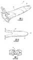
近年、以前はアクセスが困難であった領域へのアクセスを可能にする外科用アクセスシステムが開発された。1つのこうした従来技術によるシステムを図1A〜図1Cに示す。システム10は、リトラクタ20およびイントロデューサ40を含む。イントロデューサ40は、開口部52がある(図1Cに最もよく示す)円錐状遠位端42を有する。円錐状遠位端は、概して鈍い平坦面であるように構成されている。イントロデューサ40がリトラクタ10内に配置された状態で、システム10は脳組織内に挿入され、それにより、関心領域へのアクセスを可能にしながら脳組織を押しのける。システム10が関心領域まで送達されると、リトラクタ10は適所に堅固に固定される。より詳細には、リトラクタ10は、標準的なまたは従来の神経外科的固定装置を使用して空間内に固定される。リトラクタ10が適所に固定されると、リトラクタ10をその固定された位置に残して、イントロデューサ40がリトラクタ10から取り除かれ、それにより、脳組織を通して経路が生成される。しかしながら、患者の解剖学的構造に対してリトラクタ10に関するナビゲーション情報を提供するいかなる機構も提供されない。 In recent years, surgical access systems have been developed that allow access to areas that were previously difficult to access. One such prior art system is shown in FIGS. 1A-1C.
アクセスシステム10は、一定の脳組織にアクセスする方法を提供することができるが、鈍い形状の遠位端が、実際には、外科的細胞減少(cytoreduction)の後に、血管、脳神経、神経線維束および神経束の損傷のために、一時的なまたは永久的な神経障害において現れる可能性がある、繊細な組織構造の一過性のまたは永久的な変形および外傷もたらす可能性がある。開口部52が組織の芯抜き(coring)をもたらす可能性があり、イントロデューサ40が組織に押し通される際に組織および構造の損傷に至る可能性もある。さらに、リトラクタ10の配置を堅固に固定することにより、リトラクタ10の操作が、妨げられ、かつ、リトラクタ10に対する周囲構造に関する重要情報が得られずに、リトラクタ10の微小の移動に対してさえも再配置するために緩めかつ再度締めることにより一定の注意を必要とし、それにより処置時間が長くなる。 Although the
対処する必要がある別の問題は可視性である。通常、外科処置でアクセスシステムを採用する場合、それは、十分に照明されないトンネルで手術するようなものであることが多い。照明を提供するために、内視鏡等、イントロデューサシース内に光源を配置することが知られている。しかしながら、内視鏡を使用する場合、光源は、イントロデューサシース内の著しい量の作業空間を占め、したがって、他の器具に対する機能的作業領域が低減するとともに、手術部位内で他の器具を移動させる能力が最小限になる。 Another issue that needs to be addressed is visibility. Usually, when an access system is employed in a surgical procedure, it is often like operating in a tunnel that is not well illuminated. It is known to place a light source in an introducer sheath, such as an endoscope, to provide illumination. However, when using an endoscope, the light source occupies a significant amount of work space within the introducer sheath, thus reducing the functional work area for other instruments and moving other instruments within the surgical site. The ability to be minimized.
別法として、顕微鏡またはエクソスコープ(exoscope)等の遠隔または外部の位置から光を送達しなければならない。しかしながら、顕微鏡およびエクソスコープの場合、外部光源は、手術野において外科医および/または器具によって妨げられることが多い。最低でも、実際の手術作業および/または治療が発生しており、かつ有効な視覚化が最も必要である、イントロデューサシースの遠位端において有効性が大幅に弱まる。 Alternatively, light must be delivered from a remote or external location, such as a microscope or exoscope. However, for microscopes and exoscopes, the external light source is often obstructed by the surgeon and / or instrument in the surgical field. At a minimum, effectiveness is greatly diminished at the distal end of the introducer sheath where actual surgical tasks and / or treatments are occurring and effective visualization is most needed.
撮像技術ならびにフレームおよびフレームなし両方の定位画像誘導技法における上述した利点にも関らず、改善されたナビゲーション機能を含む、脳組織に対して手術する改善された外科手術技法および装置が依然として必要とされている。 Despite the above-described advantages in both imaging techniques and stereotactic image guidance techniques, both frame and frameless, there remains a need for improved surgical techniques and devices that operate on brain tissue, including improved navigation capabilities. Has been.
改善されかつ有効な治療レジメンおよびオプションもまた必要とされている。従来、病変組織が除去されると、患者は、通常、全身的に送達され(全身に影響を与える)、健康組織を殺すことなく癌細胞および組織を殺すために十分な毒の間のバランスを提供するように設計された、包括的かつ厳しい化学療法プロトコルレジメンを含む、画一的な手法で治療される。放射線に対する高用量および複数回の曝露もまた、通常、Gamma KnifeおよびCyber Knife等の製品によって使用され送達される。しかしながら、こうした治療レジメンは、有効な治療計画を見つけることを目指して患者に対する一連の「実験」でしかないことが多い。したがって、包括的な治療レジメンおよび連続的な変更の有効性を確認するために、患者をモニタリングしなければならず、健康な組織を残すことと患者全体に対する治療プロセスの毒効果とのバランスをとるように試みながら、先の成功または失敗の各々のプラスの結果またはマイナスの結果に基づいて、治療レジメンの微調整が行われる。こうした治療レジメンにより、実際には、治療レジメンが疾患に対処するように達成されるまで、患者が実験台になるか、または大部分の脳腫瘍の場合、患者は疾患により死亡する。不都合なことに、脳腫瘍の場合、患者は、有効な治療レジメンが達成される前に疾患に倒れることが多い。患者に対して非常に生物学的に苛性であるこれらの大胆な臨床努力に関らず、現行の治療パラダイムのいずれもめったに効力がない。実際には、脳腫瘍と判断された患者は、通常、疾患の初期診断から9か月〜14か月を超えて生存しないことが多いため、これらの患者において、全身化学放射線療法または標的指向性放射線療法の長期の臨床的意味は未知であり、患者が、真の影響が理解されるように十分長く生存する場合、悪影響を及ぼす可能性がある。 There is also a need for improved and effective treatment regimens and options. Traditionally, once the diseased tissue is removed, the patient is usually delivered systemically (affecting the whole body), balancing the poison between enough cancer cells and tissues to kill without killing healthy tissue. Treated in a uniform way, including a comprehensive and rigorous chemotherapy protocol regimen designed to provide. High doses and multiple exposures to radiation are also typically used and delivered by products such as Gamma Knife and Cyber Knife. However, such treatment regimens are often only a series of “experiments” on patients aiming to find an effective treatment plan. Therefore, patients must be monitored to ensure the effectiveness of a comprehensive treatment regimen and continuous change, balancing the toxic effects of the treatment process on leaving the patient healthy and the entire patient While trying, the treatment regimen is fine-tuned based on the positive or negative outcome of each previous success or failure. With such a treatment regimen, the patient actually becomes a lab bench until the treatment regime is achieved to address the disease, or in the case of most brain tumors, the patient dies from the disease. Unfortunately, in the case of brain tumors, patients often fall into disease before an effective treatment regime is achieved. Despite these bold clinical efforts that are very biologically caustic to the patient, none of the current treatment paradigms are rarely effective. In practice, patients who are determined to have brain tumors usually do not survive more than 9-14 months from the initial diagnosis of the disease, so in these patients systemic chemoradiotherapy or targeted radiation The long-term clinical implications of therapy are unknown and can have adverse effects if patients survive long enough so that the true effects are understood.
さらに、大部分の現行の治療処置レジメンは、免疫療法または化学療法レジメンを全身的に送達することを含み、血流を介する送達に依存する。しかしながら、中枢神経系(CNS)における脳細胞外流体から循環する血液を分離する役割を果たす血液−脳関門は、血流を通して脳の所定の領域に治療薬を送達するさらなる難題をもたらす。より詳細には、血液−脳関門は、実際には、神経保護の役割で機能する。したがって、血液−脳関門は、実際には、脳への治療薬の送達を妨げる。本来は治療に有効であり得る治療分子は、通常、血液脳関門のふるいより大きい分子であり、この理由で、適切な量が血液脳関門を横切らない。血液脳関門のほかに、体内には、肝臓および腎臓等、異質の物質および化学物質をろ過して取り除く他の機構が存在する。これらのろ過は、中枢神経系疾患に対する治療の意図された部位への適切な濃度の治療薬(therapeutics)の送達に対してさらなる難題をもたらす。 In addition, most current therapeutic treatment regimens involve delivering an immunotherapy or chemotherapy regimen systemically and rely on delivery via the bloodstream. However, the blood-brain barrier, which serves to separate circulating blood from brain extracellular fluid in the central nervous system (CNS), poses additional challenges for delivering therapeutic agents through the blood stream to certain areas of the brain. More specifically, the blood-brain barrier actually functions in a neuroprotective role. Thus, the blood-brain barrier actually impedes the delivery of therapeutic agents to the brain. Therapeutic molecules that may be therapeutically effective are usually molecules that are larger than the blood brain barrier sieve, and for this reason, adequate amounts do not cross the blood brain barrier. In addition to the blood-brain barrier, there are other mechanisms in the body that filter out foreign substances and chemicals, such as the liver and kidneys. These filtrations pose additional challenges for the delivery of appropriate concentrations of therapeutics to the intended site of treatment for central nervous system diseases.
血液脳関門に関連する治療問題を克服するために、血液脳関門の機械的開放が提案されたが、それは処置を複雑にする可能性がある。さらに、より小さい粒子(すなわちナノ粒子)の使用が提案され、それにより、より小さい粒子は、血液脳関門を通過するように寸法が決められ、それにより、より大きくかつより有効な治療分子を形成するように再結合されるように試みられる。しかしながら、場合によっては、より小さい粒子は治療レベルで再結合し損なう。血液脳関門を突破する他の手段には、治療レベルでより大きい粒子がそれを横切ることができる期間を考慮して、血液脳関門を一時的に開放するように設計された化学物質を送達することがある。血液脳関門を横切ると、治療処置は依然として疾患部位に到達しなければならず、それにより病変組織とともに健康な組織に毒を与えることになる。 In order to overcome the therapeutic problems associated with the blood brain barrier, mechanical opening of the blood brain barrier has been proposed, which can complicate the procedure. In addition, the use of smaller particles (ie nanoparticles) is proposed, whereby the smaller particles are sized to cross the blood brain barrier, thereby forming larger and more effective therapeutic molecules An attempt is made to recombine. However, in some cases, smaller particles fail to recombine at therapeutic levels. Other means of breaking through the blood-brain barrier deliver chemicals designed to temporarily open the blood-brain barrier, taking into account the period during which larger particles can cross it at the therapeutic level Sometimes. Crossing the blood brain barrier, the therapeutic treatment must still reach the disease site, thereby poisoning healthy tissue as well as the diseased tissue.
さらに、癌および他の異常等、脳の所定の疾患は、ウイルスまたは細菌のように振る舞うことが多く、それは、それらが、一端治療されるがそれらに送達される治療レジメンによって根絶されず、変形し、それらに先に送達された治療薬に対して耐性があるようになる可能性があるためである。これらの残留の影響を受けていない異常な細胞は、それらに先に送達された治療薬(therapy)に対して耐性があることになる細胞の変形に変異する可能性がある。機能性疾患の場合、脳組織に対する治療の有効性が、評価することが困難である可能性がある。 In addition, certain diseases of the brain, such as cancer and other abnormalities, often behave like viruses or bacteria, as they are treated once but are not eradicated by a treatment regimen delivered to them, deformed This is because they may become resistant to the previously delivered therapeutic agent. Abnormal cells that are not affected by these residuals can be mutated into cell deformations that would be resistant to the therapeutics previously delivered to them. In the case of functional diseases, the effectiveness of treatment on brain tissue can be difficult to evaluate.
したがって、健康組織および病変組織ではなく病変組織に標的治療薬を提供しながら、血液脳関門によってもたらされる難題を克服する有効な治療レジメンが必要とされている。治療の有効性を評価する方法もまた必要とされている。 Therefore, there is a need for an effective treatment regimen that overcomes the challenges posed by the blood brain barrier while providing targeted therapeutics to the diseased tissue rather than the healthy and diseased tissue. There is also a need for methods of assessing the effectiveness of treatment.
本開示の一態様によれば、外側シースおよび閉塞具を備える外科用アクセスアセンブリが開示されている。外側シースは、開放遠位端および開放近位端によって画定され、それらの間に中空本体を有している。閉塞具は、遠位端および近位端によって画定され、遠位端は、遠位先端で終端する先細遠位先端部材をさらに備えている。閉塞具は、先細遠位先端部材が、閉塞具が導入形態にあるときに外側シースの開放遠位端から突出するように、外側シース内に受け入れられるように構成されている。 According to one aspect of the present disclosure, a surgical access assembly is disclosed that includes an outer sheath and an obturator. The outer sheath is defined by an open distal end and an open proximal end and has a hollow body therebetween. The obturator is defined by a distal end and a proximal end, the distal end further comprising a tapered distal tip member terminating at the distal tip. The obturator is configured to be received within the outer sheath such that the tapered distal tip member projects from the open distal end of the outer sheath when the obturator is in the introduced configuration.
一実施形態では、外側シースの遠位端は丸みが付けられたリムをさらに備えている。 In one embodiment, the distal end of the outer sheath further comprises a rounded rim.
一実施形態では、外側シースの開放近位端に把持部が固定されている。把持部の外面に凹凸を付けることができる。一実施形態では、把持部を通して形成された少なくとも1つの小さな開口部が凹凸をもたらす。別の実施形態では、把持部を中心に等距離に間隔を空けて配置された複数の小さい開口部が凹凸を形成する。 In one embodiment, a grip is secured to the open proximal end of the outer sheath. Unevenness can be provided on the outer surface of the gripping portion. In one embodiment, at least one small opening formed through the gripper provides irregularities. In another embodiment, a plurality of small openings that are spaced equidistantly about the gripping portion form irregularities.
1つの例示的な構成では、把持部の周辺部から位置決め部材が延在することができる。 In one exemplary configuration, the positioning member can extend from the periphery of the gripper.
1つの例示的な構成では、外側シースの本体部は透明である。 In one exemplary configuration, the body portion of the outer sheath is transparent.
一実施形態では、本体部は、外側シースの所定位置を視覚的に示すように構成された少なくとも1つの基準指標をさらに備えている。複数の指標を設けることができ、指標は、本体部の周縁に互いに等距離に間隔を空けて配置されている。一実施形態では、基準指標は、近位端から遠位端まで延在する長手方向指標である。一実施形態では、基準指標は、本体部の内面および外面のうちの一方に画像形成可能な可視インクによって印刷されている。一実施形態では、本体部の内面および外面のうちの一方にエッチングされた基準指標。一実施形態では、複数の指標は、一連の間隔を空けて配置された小さい穴および非貫通窪み(divot)のうちの1つである。 In one embodiment, the body further comprises at least one reference indicator configured to visually indicate a predetermined position of the outer sheath. A plurality of indicators can be provided, and the indicators are arranged at equal distances from each other on the periphery of the main body. In one embodiment, the reference indicator is a longitudinal indicator that extends from the proximal end to the distal end. In one embodiment, the reference index is printed with visible ink capable of forming an image on one of the inner surface and the outer surface of the main body. In one embodiment, a reference index etched on one of an inner surface and an outer surface of the body portion. In one embodiment, the plurality of indicia is one of a series of spaced-apart small holes and non-through divots.
閉塞具は、遠位端と近位端との間に延在する本体部をさらに備えることができ、近位端に固定して接続されたハンドル部をさらに備え、ハンドル部は、第1止め部材および把持部材をさらに備えている。ハンドル部には係止部材を作動的に接続することができ、係止部材を受け入れる受入穴と連通する係合開口部を設けることができる。係合開口部は、係止部材をハンドル部に保持するように構成された保持部材を受け入れるチャネルと連通している。 The obturator may further comprise a body portion extending between the distal end and the proximal end, further comprising a handle portion fixedly connected to the proximal end, the handle portion being a first stop. A member and a gripping member are further provided. A locking member can be operatively connected to the handle portion and an engagement opening communicating with a receiving hole for receiving the locking member can be provided. The engagement opening is in communication with a channel that receives a retaining member configured to retain the locking member on the handle portion.
1つの例示的な実施形態では、本体部は、少なくとも1つの空隙領域をさらに備えている。 In one exemplary embodiment, the body portion further comprises at least one void area.
一実施形態では、本体部は、本体部の外面に少なくとも1つの補償突起をさらに備えることができる。 In one embodiment, the body portion may further include at least one compensation protrusion on the outer surface of the body portion.
本体部は、内部に配置されたチャネルセグメントをさらに備えることができ、チャネルセグメントはナビゲーション部材を受け入れるように構成されている。一構成では、チャネルセグメントは、先細遠位先端部材の近位縁と整列する窪み内で終端する。 The body portion can further comprise a channel segment disposed therein, the channel segment being configured to receive a navigation member. In one configuration, the channel segment terminates in a recess aligned with the proximal edge of the tapered distal tip member.
一実施形態では、閉塞具は、先細遠位先端部材に配置された少なくとも1つの観察窓をさらに備え、観察窓は、組織の視覚化を可能にするように観察部材を受け入れるように構成されたチャネルと連通している。 In one embodiment, the obturator further comprises at least one viewing window disposed on the tapered distal tip member, wherein the viewing window is configured to receive the viewing member to allow tissue visualization. Communicate with the channel.
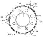
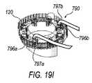
一実施形態では、外科用アクセスアセンブリは、外側シースの一部に作動的に連結する照明リングをさらに備えており、照明リングは、上面と、壁部材と、照明リングによって支持された少なくとも1つの光素子とを備えており、照明リングの上面を通してアクセス開口部が形成されている。 In one embodiment, the surgical access assembly further comprises an illumination ring that is operatively coupled to a portion of the outer sheath, the illumination ring comprising at least one of a top surface, a wall member, and the illumination ring. And an access element is formed through the upper surface of the illumination ring.
一実施形態では、光素子は複数のLED照明である。複数の光素子を設けることができ、それら光素子は、アクセス開口部を中心に等距離に間隔を空けて配置されている。 In one embodiment, the light element is a plurality of LED lights. A plurality of optical elements can be provided, and the optical elements are arranged equidistantly around the access opening.
一実施形態では、照明リングの壁は、外側シースに照明リングを選択的に固定するように位置決め要素を受け入れるように構成された壁開口部をさらに備えている。 In one embodiment, the wall of the illumination ring further comprises a wall opening configured to receive a positioning element to selectively secure the illumination ring to the outer sheath.
一実施形態では、閉塞具、外側シースまたは光リングのうちの1つをナビゲーションシステムに作動的に接続するナビゲーション部材が提供される。ナビゲーション要素は、使用中に患者の体内における外側シースまたは閉塞具の位置を示すように構成されている。ナビゲーション部材は、RFIDチップ、センサ、超音波プローブ、複数の反射部材、アレイ、または閉塞具内に配置された撮像デバイスのうちの1つであり得る。 In one embodiment, a navigation member is provided that operatively connects one of an obturator, outer sheath or light ring to a navigation system. The navigation element is configured to indicate the position of the outer sheath or obturator within the patient's body during use. The navigation member can be one of an RFID chip, a sensor, an ultrasound probe, a plurality of reflective members, an array, or an imaging device disposed within the obturator.
一実施形態では、ナビゲーション要素は、外側シースの一部に永久的に取り付けられる。別の実施形態では、ナビゲーション要素は、外側シースの本体部内に埋められるかまたは成形される。 In one embodiment, the navigation element is permanently attached to a portion of the outer sheath. In another embodiment, the navigation element is embedded or molded into the body portion of the outer sheath.
一実施形態では、照明リングは、照明リングの壁部材の周辺部に配置された少なくとも1つの外側に延在するフランジ部材をさらに備え、ナビゲーション要素は、フランジ部材に作動的に取り付けられた少なくとも1つのセンサを含む。少なくとも1つのセンサは、照明リングに配置された回路基板に電気的に接続されている。 In one embodiment, the lighting ring further comprises at least one outwardly extending flange member disposed at the periphery of the wall member of the lighting ring, wherein the navigation element is at least one operatively attached to the flange member. Includes two sensors. At least one sensor is electrically connected to a circuit board disposed on the illumination ring.
一実施形態では、照明リングは、照明リングの壁部材の周辺部に配置された複数の外側に延在するフランジ部材をさらに備え、ナビゲーション要素は、位置指標としての役割を果たす複数の反射ボールを含み、反射ボールのうちの1つは各フランジ部材に取り付けられている。 In one embodiment, the illumination ring further comprises a plurality of outwardly extending flange members disposed at the periphery of the wall member of the illumination ring, and the navigation element comprises a plurality of reflective balls that serve as position indicators. One of the reflective balls is attached to each flange member.
一実施形態では、外側シースに取り付けられるように構成された支持リングが提供される。ナビゲーション要素は、支持リングが外側シースに接続されると、ナビゲーションシステムが、患者の解剖学的構造に対して外側シースの位置を示すように外側シースの位置を追跡するように構成されるように、支持リングに取り付けられている。 In one embodiment, a support ring configured to be attached to the outer sheath is provided. The navigation element is configured such that when the support ring is connected to the outer sheath, the navigation system is configured to track the position of the outer sheath to indicate the position of the outer sheath relative to the patient anatomy. Attached to the support ring.
ここで、添付図面を参照して、本開示の例示的な実施形態についてより詳細に説明する。 Exemplary embodiments of the present disclosure will now be described in more detail with reference to the accompanying drawings.
ここで、以下の考察を参照し図面も参照すると、開示されているアセンブリおよび方法に対する例示的な手法が詳細に示されている。図面は、いくつかのあり得る手法を表しているが、図面は必ずしも正確な縮尺ではなく、本開示をよりよく例示し説明するために、いくつかの特徴を誇張し、取り除き、または部分的に分割している場合がある。さらに、本明細書に示す説明は、網羅的であるように、または他の方法で、図面に示しかつ以下の詳細な説明に開示する正確な形態および構成に特許請求の範囲を限定または制限するようには意図されていない。 Referring now to the following discussion and also to the drawings, exemplary approaches to the disclosed assemblies and methods are shown in detail. Although the drawings depict some possible approaches, the drawings are not necessarily to scale, and some features have been exaggerated, removed, or partially illustrated in order to better illustrate and explain the present disclosure. It may be divided. Further, the description provided herein is intended to be exhaustive or otherwise to limit or limit the scope of the claims to the precise form and construction shown in the drawings and disclosed in the following detailed description. It is not intended to be.
本明細書には、外科用アクセスアセンブリと、それを使用するためのさまざまな構成要素と、外科用アクセスアセンブリを使用する方法とが記載されている。本明細書に開示する構成要素は、外科医に対し、患者に対する外傷を最小限にする強化された能力を提供する一方で、たとえば頭蓋内外科手術技法等、効率的な改善された低侵襲性外科手術技法を提供する。本明細書に開示する構成要素を、目標が絞られかつ有効な治療レジメンの適用のためにさらに使用することができる。 Described herein are surgical access assemblies, various components for using the same, and methods of using the surgical access assembly. The components disclosed herein provide the surgeon with enhanced ability to minimize trauma to the patient while efficiently improving minimally invasive surgery such as, for example, intracranial surgical techniques. Provide surgical techniques. The components disclosed herein can further be used for the application of targeted and effective treatment regimens.
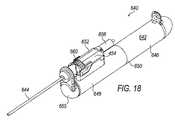
図2を参照すると、外科用アクセスアセンブリ100の断面斜視図が示されている。1つの例示的な構成では、外科用アクセスアセンブリ100は、中空外側シース102および選択的に取外し可能な閉塞具104を備えている。図2に最もよく示すように、閉塞具104は、外側シース102の長さより長い長さであるように構成されており、それにより、後により詳細に考察するように、閉塞具104の遠位端106は、遠位端108外側シース102から所定の距離だけ突出している。 Referring to FIG. 2, a cross-sectional perspective view of
係止部材110もまた設けることができる。係止部材100は、後により詳細に考察するように、閉塞具104内に別個のナビゲーション部材112(仮想線で示す)を作動的に保持するように構成されている。係止部材110が閉塞具104から完全に外れないように、閉塞具104の一部の中に保持部材114を固定することができる。 A locking
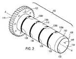
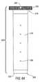
ここで図3〜図5を参照して、外側シース102についてより詳細に説明する。外側シース102は、遠位端108および近位端116によって画定され、略中空本体部118および把持部120を有している。1つの例示的な実施形態では、把持部120は、図面に示すように、リングとして構成されている。しかしながら、把持部120は必ずしもリングとして構成される必要はないことが理解される。説明を容易にするために、把持部120を、以降、把持リング120と呼ぶ。把持リング120は、近位端116において本体部118に固定して取り付けられている。1つの例示的な構成では、本体部118は、正常な組織、異常な組織とともに、外側シース102がこうした組織内に配置されたときに本体部118の外側に配置される重要構造が見えるのを可能にする透明な生体適合性材料から構成されている。1つの例示的な構成では、外側シース102はポリカーボネートから構成されているが、樹脂を含む他の生体適合性材料を採用することができる。 The
1つの例示的な構成では、腫瘍、脈管、神経線維束、神経束およびさらには健康な組織のリアルタイムでの視覚化を可能にする撮像機構を、外側シース102に組み込むことができる。実際には、後にさらに詳細に説明するように、撮像機構は、生理学的機能的撮像法によって、可視であるべき皮質線維軌道の特徴に関する情報が提供され得るようにし、それにより、術者が、脳内の所望の位置にアクセスすることができる間に、こうした線維を切断し、引き伸ばし、場合によっては損傷を与えるのではなく、外側シース102のいずれかの側においてこうした線維を分離し待機させておくことができる。さらに、後にさらに詳細に説明するように、撮像機構はまた、外科医が、神経線維束および神経束の位置に関するリアルタイム情報を、外側シース104を配置した後、かつそこを通しての異常部位切除処置中に得ることができるようにすることも可能である。白質路撮像に加えて、脳血流の特徴のマッピングを得ることができる。 In one exemplary configuration, an imaging mechanism that allows real-time visualization of tumors, vessels, nerve fiber bundles, nerve bundles and even healthy tissue can be incorporated into the
1つの例示的な実施形態では、撮像機構は、外側シース102に組み込まれる超音波プローブであり得る。たとえば、外側シース102の、外側シース102を画定する壁の中に、1つまたは複数の小径超音波プローブとともに構成される1つまたは複数のチャネルを設けることができる。別の構成では、外側シース102内に受け入れられるように構成される単一の超音波プローブを設けることができる。さらに別の実施形態では、高度な撮像法を提供するように、外側シース102に低磁場MRIプローブを選択的に配置することができる。さらに別の実施形態では、低磁場MRI撮像コイルを、外側シース102内に成形または接合することができる。さらに別の例示的な構成では、プローブは、光コヒーレントトモグラフィ(OCT)撮像法または分光法であり得る。 In one exemplary embodiment, the imaging mechanism may be an ultrasound probe that is incorporated into the
別の例示的な構成では、後にさらに詳細に説明するように、外側シース102に対して、術者が、関心領域における配置の後に外側シャフト102の位置を「読み取る」とともに、処置中に外側シース102の位置を更新することを可能にする、ナビゲーション機能を提供することも(または別法として提供することが)可能である。1つの例示的な構成では、ナビゲーションシステムによって追跡されるように構成されるRFIDチップまたはセンサを、外側シース102に組み込むことができる。たとえば、RFIDチップまたはセンサを外側シース102に、たとえば、RFIDチップまたはセンサをそこに埋めるかまたは成形することにより、永久的に取り付けることができる。他の例示的な構成では、一時的なセンサまたはチップを外側シース102に組み込むかまたは取り付けることができる。たとえば、外側シース102の、外側シース102を画定する壁の中に1つまたは複数のチャネルを設けることができる。RFIDチップおよび/またはセンサをそのチャネル内に配置することができる。別法として、RFIDチップおよび/またはセンサを把持リング120内に配置することができる。 In another exemplary configuration, with respect to the
さらに別の代替構成では、RFIDチップまたはセンサを把持リング120に取り付けることができる。さらに、さらに別の構成では、把持リング120の遠位に面する面(図3に最もよく示す)に(図11H〜図11Iに関連して後述するものに類似する)反射ボールを取り付けることができる。反射ボールは、光学画像誘導システムに関連して使用されるタイプの反射器のアレイ等、画像誘導位置指標として作用する。こうしたシステムと使用される赤外線反射ボールは、外側シースを識別するように校正された通例の三角形の形態で、画像/ナビゲーション誘導システムに取り付けられる。 In yet another alternative configuration, an RFID chip or sensor can be attached to the
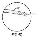
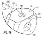
外側シース102の遠位端108を、外側シース102の遠位端108の開口部134を包囲する遠位縁132まで外側シース102の中心軸A−Aに向かって延在する先細部130があるように構成することができる。先細部130は、閉塞具104の本体部168を画定する直径から外側シース102の本体部118を画定する直径まで、組織の引きずり、外傷または芯抜きなしに、外側シース102と遠位端部172との間の遷移を容易にする役割を果たす。1つの例示的な構成では、遠位端108を、外科用アクセスアセンブリ100が脳内に挿入されたときに脳組織の平滑な/非外傷性の遷移をもたらすように丸み(radius)または他の形態を有するように構成することができる。 There is a
たとえば、図4Bに最もよく示すように、遠位縁132は、非鋭利であり丸みがあるように構成されている。1つの例示的な構成では、遠位縁132は、0.3mm径の丸みが付けられたリムとして構成される。先細部130および丸みが付けられた遠位先端132は、閉塞具104と協働して、組織とともに白質を含む脳内のさまざまな構造を、組織またはこうした構造を切断することなく外側シース102から離れるように非外傷的に移動させる。実際には、鈍い先端遠位端かまたは図1Cに示すもののような先細前縁のいずれかを含む従来技術による装置とは異なり、丸みが付けられた遠位先端132は先細部130および閉塞具104と協働してさまざまな組織に対する打撲傷および損傷を防止する。より詳細には、この構成により、外側シース102が繊細な組織に、こうした繊細な組織を切断することなく入るのが容易になる。外科用アクセスアセンブリ100の挿入については、後にさらに詳細に説明する。 For example, as best shown in FIG. 4B, the
本体部118に、複数の間隔を空けて配置された指標136をさらに設けることができる。指標136は、図3に示すように、概して、本体部118の周縁に延在し、各々、本体部118における所定位置を視覚的に示す二次指標138をさらに組み込むことができる。図3は4つの指標136を示すが、本体部118を種々の長さで設けることができ、いかなる数の指標136も設けることができることが理解される。本体部118に、長手方向指標140を設けることも可能である。より詳細には、図4Aに最もよく示すように、長手方向指標140は、近位端116から遠位端108まで延在している。指標136、138および140を、たとえば、フルロデオキシグルコース(FDG)、テクニチウム99、ガドリニウム、チタンの粉じん、硫酸バリウム、上記または他の好適な撮像材料の組合せを含むインク等、撮像用可視インクで、本体部118の内面または外面のいずれかに印刷することができる。指標136および138は、構造が本体部118を通して可視であり得るため、システム100の操作者に対して基準点を提供する。指標136、138および140を、関心領域の容易な特定を可能にするように、MRI、CT、PETまたは他のあらゆる好適な撮像モダリティの下で可視であるように構成することも可能である。1つの代替実施形態では、指標136、138および/または140を、本体部118に、本体部118の内面または外面のいずれかにエッチングまたは印刷することができる。 The
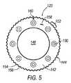
把持リング120の詳細を図5に最もよく示す。把持リング120は、概して、外側周辺部144および内側開口部146によって画定されるフランジ部材142として構成されている。内側開口部146に対し、本体部118によって画定される内腔148の直径に概して対応するように寸法を決めることができる。外側周辺部144は、本体部26の内腔148より大きい直径を有するように寸法が決められる。フランジ部材142に、その内部に配置される1つまたは複数の小さい開口部150をさらに設けることができる。1つの例示的な構成では、内側開口部146を中心に概して等距離に間隔が空けられて配置されている複数の小さい開口部150が設けられている。小さい開口部150については後にさらに詳細に説明する。外側シース102の把持を容易にするために、外側周辺部144に凹凸面152をさらに設けることができる。たとえば、1つの例示的な構成では、凹凸面152は、複数の交互の隆起154および溝156を含む。しかしながら、他の凹凸面を採用することができることが理解される。 Details of the
フランジ部材142の近位端面158に配置して、位置合せ機構160を採用することができる。位置合せ機構160を使用して、外側シース102が脳内に配置されたときに長手方向指標140の位置が示される。位置合せ機構160については、後により詳細に考察する。 An
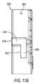
図6A〜図6Bに、外側シース202の代替実施形態を示す。外側シース202は、遠位端208、近位端216および本体部218によって画定されるという点で外側シース102に類似している。遠位縁232が、概して遠位先端132と同様に構成されている。把持リング220が本体部218に固定して取り付けられている。 An alternative embodiment of the
把持リング220もまた凹凸面252を有している。把持リング220は位置決め部材262をさらに備えている。位置決め部材262は、照明リング(図11Aに最もよく示す)300を外側シース102に作動的に接続するように構成されている。図示するように、1つの例示的な構成では、位置決め部材262は、把持リング220の外側周辺部244から外側に延在している。位置決め部材262はまた、長手方向指標240の位置を示す位置合せ機構としての役割も果たすことができる。別法として、別個の位置合せ機構260を設けることができる。たとえば、図6Bにおいて、位置合せ機構260は、位置決め部材262に隣接して配置されている。 The
動作時に外側シース202の位置決めに役立つように、本体部218にもまた指標34、36および38を設けることができる。しかしながら、別の代替構成では、本体部218に、特定の撮像モダリティの下でシグナルボイドまたは最小限のアーチファクトを生成する指標264を設けることができる。1つの特定の構成では、図6Aに示すように、指標264を、所定距離間隔を空けて配置される小さい穴として構成することができる。さらに別の代替構成では、指標264を非貫通窪みとして構成することができる。さらにさらなる代替構成では、指標264を、本体部218の内面または外面のいずれかの長手方向溝(図示せず)として構成することができる。
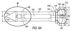
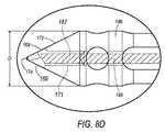
ここで、図7〜図10を参照して閉塞具104について説明する。閉塞具104は、遠位端106、近位端166、本体部168およびハンドル部170によって画定される。遠位端106は、組織の非外傷性の拡張を提供するように先端部材174まで先細りになっている略円錐形遠位端部172を有するように構成されている。1つの例示的な構成では、先端部172は、閉塞具104が脳内に挿入される際の組織の芯抜きを防止するように、閉鎖された先端部材174に向かって先細りになっている。 Here, the
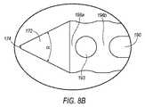
先端部172の先細りを画定する角度αの選択を行う複数の変量がある。これらの変量としては、閉塞具104の外径D1のサイズと、遠位先端部172が本体部168から延在する所望の長さと、ナビゲーション部材112の遠位先端および先端部材174に対する所望のオフセットとが挙げられる。より詳細には、外科用アクセスアセンブリ100は、外科医に対して、脳内の関心領域にアクセスするための柔軟性を提供するように種々の直径サイズおよび長さの選択を提供するように、複数のサイズの外側シース102および閉塞具104を含むことができるキットの一部として提供されることが企図される。しかしながら、閉塞具104のいずれのサイズの直径D1が使用されるかに関らず、遠位先端174が確定可能であることを確実にするために、先細り角度αを選択的に調整することができる。ナビゲーション部材112を利用し、ナビゲーション部材112がその遠位端を(後にさらに詳細に説明するように)閉塞具104内の所定位置に配置する実施形態では、ナビゲーション部材112の遠位端と種々の直径D1サイズの閉塞具104における遠位先端174との間の同一のオフセット長を維持するために、直径D1が増大すると先細り角度αを増大させる必要がある。 There are a number of variables that select the angle α that defines the taper of the
たとえば、閉塞具104の直径D1が13.5mmである場合、例示的な角度αは、有効な非外傷性拡張とともに確定可能な遠位先端174位置を提供するように45.5°であり得る。しかしながら、閉塞具104の直径D1が15.5mmである場合、例示的な角度α’は52.8°であり得る。 For example, if the diameter D1 of the
図8Bに最もよく示すように、遠位先端174は、先端部材174が曲線的であり鈍くも鋭利でもないように、丸みが付けられるように構成されている。より詳細には、先端部材174は、挿入中に、脳内に見られる脈管、神経線維束および神経束等の繊細な組織を引き伸ばすかまたはさらには引裂く可能性がある、いかなる平坦部分も有していないように構成されている。さらに、先端部材174が閉鎖されているため、こうした繊細な組織および神経束の損傷も回避される。1つの例示的な実施形態では、先端部材174は0.5mm半径を有するように構成されている。後にさらに詳細に説明するように、先端部材174の構成は、それが挿入される組織を穏やかに変位させ移動させるように、すなわち、外科用アクセスアセンブリ100が組織内に挿入される際に組織を切断することとは対照的に、神経束内(intra−fascilar)および神経束の近く(para−fascilar)への導入を可能にするように組織を非外傷的に拡張するように設計されている。 As best shown in FIG. 8B, the
ハンドル部170は、閉塞具104の近位端166に配置されている。図7B、図8Aおよび図9Aに最もよく示すように、ハンドル部170は、止め部材176および把持部材178を備えている。止め部材176は、把持部材178の遠位に配置され、図8Aに最もよく示すように、本体部168の直径D1とともに外側シース102の直径D2(図4Aに示す)より大きい幅W1を有するように構成されている。把持部材178は、止め部材176の幅W1より大きい幅W2を有するように構成され、それにより段状形態を提供する。止め部材176は、把持部材178の遠位面179から軸方向に間隔が空けられている係合面177をさらに画定している。 The
1つの例示的な構成では、図7A〜図7Bおよび図10に最もよく示すように、ハンドル部170は、略平坦面180があるように構成されている。平坦面180は、係止部材110を受け入れるように構成されている受入穴182があるように構成されている。1つの例示的な構成では、受入穴182はねじ切られている。図2、図7Bおよび図8Aに最もよく示すように、受入穴182内には、係合開口部184が配置されている。係合開口部184は、ハンドル部170を通して少なくとも部分的に延在するチャネル186(図8Aおよび図9Aにおいて仮想線で示す)と連通している。係止部材110が受入穴182内に少なくとも部分的に係合した後、保持部材114(図2)はチャネル186内に配置される。係合開口部184は受入穴182に通じているため、保持部材114の一部は、係止部材110が受入穴182から完全に引き出されないように、受入穴182の一部を横切って延在する。たとえば、係止部材110は、受入穴182内の対応する雌ねじと協働するねじ山を有するように示されている。保持部材114は、受入穴182から取り除かれている際に係止部材110等の係止部材110のねじ山の上方に延在するようにチャネル186内に配置され、ねじ山は保持部材114と接触し、それにより、係止部材110がハンドル部170から完全に取り外されるのを防止する。 In one exemplary configuration, the
近位端166を通して、アクセス開口部188が形成されている。アクセス開口部188は、ハンドル部170を通って延在している。1つの例示的な構成では、アクセス開口部188には、アクセス開口部188に向かって先細りになっている内方に延在する面取り部189を設けることができる。面取り部189は、ナビゲーション部材112をアクセス開口部188に挿入するための自己方向付け(self−directing)機能を提供する。アクセス開口部188は、ハンドル部170を通って本体部168内に延在する第1チャネルセグメント191と連通している。 An access opening 188 is formed through the
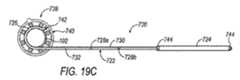
図8Dに示すように、閉塞具104を、それに作動的に接続された観察部材167を受け入れるようにさらに構成することができる。より詳細には、円錐状先端部172を、円錐状先端部172の表面と同一平面に向けられる1つまたは複数の観察窓169があるように構成することができる。観察窓169は、たとえば光ファイバケーブルまたは超音波プローブ等の観察部材を選択的に受け入れることができる観察部材チャネル171と連通している。観察部材は、ナビゲーション部材の使用に加えるかまたはその代りであり得る。観察部材により、外科医は、挿入中の外傷を最小限にするように周囲組織および脳機能上重要な組織構造をリアルタイムで(すなわち挿入中に)観察することができる。 As shown in FIG. 8D, the
本体部168は、遠位端106と近位端166との間に延在している。本体部168は、1つまたは複数の細長い空隙領域190を含む。空隙領域190は、閉塞具104の重量を低減するのに役立ち、それにより、外科処置中に閉塞具104の操作が容易になる。空隙領域190はまた、閉塞具104の本体部168内の湿気の保持により閉塞具104の滅菌も容易にする。さらに、空隙領域190はまた通気も提供し、それにより、閉塞具104が操作中に外側シース102から引き抜かれている際に真空が発生するのを防止する。
空隙領域190は、本体部168の長さの一部を通して軸方向に延在するウェブ部192によって分離されている。本体部168のウェブ部192の上には、1つまたは複数の指標194が配置されている。指標194は、閉塞具104が組織内に配置されている間に、撮像モダリティと協働して、脳内のさまざまな組織、重要構造および神経束に対する閉塞具104の位置に関する情報をリアルタイムに提供する、間隔を空けて配置されたハッシュマーク(194Aとして示す)を含むことができる。指標194はまた、閉塞具104と外側シース102との間の相対的な位置に関する情報を提供するのにも役立つ。指標194は、特定の撮像モダリティの下でシグナルボイドまたは最小限のアーチファクトを生成する。 The
本体部168は、1つまたは複数のクロスウェブ196をさらに有することができる。クロスウェブ196は、ウェブ部192に対して横切る方向に向けられ、ウェブ部192を合わせて接続する。1つの例示的な構成では、本体部168は、本体部168の外径D2を有効に画定する少なくとも1つのクロスウェブ196を有している。直径D2は、閉塞具104および外側シース102を互いに対して選択的に摺動させることができるように外側シース102の内腔148内に適合するように寸法が決められている。しかしながら、直径D2はまた、外側シース102の内面と閉塞具104の外面との間のいかなる間隙も最小限にするかまたはさらにはなくすようにも寸法が決められている。図7〜図9に示す例示的な構成では、3つのクロスウェブ196A、196Bおよび196Cが設けられている。第1クロスウェブ196Aは遠位先端部172に接続され、第2クロスウェブ196Bは、第1クロスウェブ196Aから近位に間隔を空けて配置され、空隙領域193によって分離されている。第3クロスウェブ196Cは、空隙領域192によって第2クロスウェブ196Bから分離され、ハンドル部170の第1止め部材176から遠位に配置されている。クロスウェブ196は、閉塞具104の構造的完全性とともに向上した剛性を提供する役割を果たす。 The
1つの例示的な構成では、外側シース102の内腔148の直径のわずかな製造上のばらつきに適応するように、クロスウェブ196のうちの1つまたは複数に、環状補償突起197をさらに設けることができる。たとえば、外側シース102は樹脂から成形される構成要素であり得ることが企図されるため、こうしたわずかな製造上のばらつきをもたらす可能性があるプロセス。補償突起197は、閉塞具104の外面から半径方向外側にわずかに延在し、外側シース102の内腔148と協働して、外側シース102の樹脂のわずかな可撓性のために、閉塞具104の外面と内腔148との間に摩擦嵌合をもたらす。それにより、製造時に外側シース102の高い寸法公差を維持する必要を低減する補償突起197の使用。 In one exemplary configuration, an annular compensation protrusion 197 is further provided on one or more of the
一実施形態では、クロスウェブ196Bに、そこから延在している第2チャネルセグメント198(仮想線で示す)が設けられている。第2チャネルセグメント198は、第1チャネルセグメント191と軸方向に位置合せされ、ナビゲーション部材112を選択的に受け入れるように構成されている。1つの例示的な構成では、図9Bに最もよく示すように、第1クロスウェブ196Aに、内方に延在する窪み199が配置されている。窪み199は、外側シース102が閉塞具104に組み付けられたとき、ナビゲーション部材112の遠位先端を外側シース102の遠位端108と位置合せするように構成されている。 In one embodiment, the cross web 196B is provided with a second channel segment 198 (shown in phantom) extending therefrom.
図11A〜図11Fを参照して、ここで、任意選択的な照明リング300の詳細について説明する。照明リング300は、概して、上面部302、壁部材304によって画定されている。回路基板306もまた設けることができる。上面302には、後にさらに詳細に説明するように、そこを通して、1つまたは複数の手術用器具を受け入れるように構成された少なくとも1つのアクセス開口部308がある。上面302に、追加の小さい開口部309を設けることができる。小さい開口部309のうちの1つまたは複数は、フランジ部材142に配置された小さい開口部150と位置合せされるように構成されている。壁部材304は、照明リング300内に開放空洞310をもたらすように上面302から延在している。壁部材304の外面を、把持リング120のように凹凸にすることができる(図示せず)。 Details of the
照明リング300の一部によって支持される1つまたは複数の光素子312。図11Eに示す一実施形態では、照明312は、アクセス開口部308に隣接して開放空洞310に向かって内方に面するように、上面304に固定して取り付けられている。各照明312は、ワイヤ314によって遠隔電源(図示せず)に電気的に接続されている。1つの例示的な構成では、ワイヤ314を、上面302のアクセス開口部308の周囲に形成されたチャネル内に保持することができる。 One or more
代替構成(図11F)では、照明312を回路基板306に組み込むことができる。回路基板306は、上面302に形成されたアクセス開口部308と位置合せすることができるアクセス開口部316があるように構成されている。さらに、回路基板306はまた、開放空洞310内に配置されそれに固定されるように寸法が決められている。言い換えれば、一構成では、回路基板306は、壁部材304によって画定された内径より小さい外径を有するように寸法が決められている。ワイヤ320が回路基板306を電源に電気的に接続するためのアクセスを可能にするために、上面302または壁部材304のいずれかの一部を通して壁開口部318を形成することができる。図11B、図11Dおよび図11Fに、壁開口部318の例を見ることができる。回路基板306を、照明リング300が、定常状態があるようにオンにされたとき、光の一定の出力があるように構成することができる。 In an alternative configuration (FIG. 11F), the
図11Gに、回路基板306用の例示的な回路設計321を示す。例示的な構成では、回路設計312は、照明リング300の使用中に、照明312のちらつきを防止しかつ/または照明312の1つでも動作しないことを防止するように構成されている。より詳細には、回路設計312は、1つの照明312が切れた場合、または回路に電力を供給するバッテリの残量が少なくなった場合に、照明リング300が単に遮断し、交換バッテリパック(図示せず)を使用することができるように、構成されている。 FIG. 11G shows an
1つの例示的な構成では、照明312はLED照明であるが、他の照明装置を利用することができる。LED照明は、外科用アクセスアセンブリ100の重量を著しく増大させず、また臨床的に重大な量の熱を放散しない。さらに、LED照明は、組織の識別を可能にする蛍光染料の視覚化を改善するように、照明リング300に組み込むことができる色/周波数の種々の組合せの光を放出することができる。 In one exemplary configuration, the
LED照明の使用により、内視鏡を、外科用アクセスアセンブリ100とともに、ただし付随する光ファイバ光源なしに使用することができる。この構成により、内視鏡の必要な全体的な外径が著しく低減し、それにより、外側シース102の内腔148内の作業空間が改善する。より詳細には、外側シース102の内腔148にはより広い作業空間があり、それにより、複数の器具類のより多くの同時使用が可能になるとともに視覚化が改善される。さらに、従来の内視鏡装置は、イントロデューサカニューレに固定される支持構造に取り付けなければならないため、こうしたアセンブリの重量が、イントロデューサカニューレを一方向に引き寄せる傾向がある。この動作は、処置中のイントロデューサカニューレの配置を危うくし、かつ/または脳組織に外傷をもたらす可能性がある。したがって、照明リング300を外側シースに組み込むことにより、こうした潜在的な不都合を回避することができる。 Through the use of LED illumination, the endoscope can be used with the
照明リング300を外側シース102の把持リング120にあらゆる好適な方法で固定することができるが、1つの例示的な構成では、照明リング300を把持リング120の選択的に固定するために、照明リング300に選択的係止装置が設けられる。1つの例示的な構成では、壁部材304に係止チャネル322が設けられる(図11Bに最もよく示す)。係止チャネル322は、第1チャネルセグメント324と第1チャネルセグメント324と連通している第2チャネルセグメント326とに通じる壁開口部318を備えている。壁開口部318は、壁部材304の底面328から延在している。第2チャネルセグメント326は、壁部材304の底面328から上方に間隔を空けて配置され、第1チャネルセグメント324から角度をなして向けられている。1つの例示的な構成では、第2チャネルセグメント326は、第1チャネルセグメント324から90°に向けられている。 Although the
係止チャネル322は、位置決め部材262と協働して、照明リング300を把持リング120に選択的に固定する。より詳細には、照明リング300は、位置決め部材262が壁開口部318に入った状態で、把持リング120の上に押し下げられる。照明リング300が下方に押し下げられると、位置決め部材262は第1チャネルセグメント324内を通る。位置決め部材262が、第1チャネルセグメント324の終端330と接触すると、照明リング300は、位置決め部材262が第2チャネルセグメント326内に移動するように外側シース102に対して回転させられ、それにより図12に示すように、照明リング300を外側シース102に選択的に係止する。接続されると、照明リング300は、それにより、外側シース102の内腔148を照明するハンズフリー光源を提供する。 The locking
1つの例示的な構成では、外側シース102のいくつかのセグメントを、外側シース102内の視覚化を向上させるために光を反射するように艶消しにすることができる。たとえば、先細部130を艶消しにすることができる。同様に、把持リング120の頂部もまた艶消しにすることができる。 In one exemplary configuration, several segments of the
図11H〜図11Iを参照すると、照明リング350の代替構成が示されている。照明リング350は照明リング300に類似しており、図11H〜図11Iには、上面302、壁部材304、アクセス開口部308、開放空洞310、小さい開口部309および壁開口部318等の共通の要素も示されている。図11H〜図11Iに示す実施形態は、外側に延在するフランジ部材352をさらに含む。一構成では、フランジ部材352は、照明リング350の外周と一体的に形成されている。図示する実施形態は、照明リング300の壁部材の周辺部に等距離に間隔を空けて配置された3つのフランジ部材352を含むが、いかなる数のフランジ部材352を設けることも可能であることが理解される。さらに、フランジ部材352を、周辺部にあらゆる構成で配置することができる。 Referring to FIGS. 11H-11I, an alternative configuration of the illumination ring 350 is shown. Illumination ring 350 is similar to
フランジ部材352は、センサ354(図11Iを参照)または位置指標としての役割を果たす反射ボールを支持する。より詳細には、センサ354は、ナビゲーションシステム(後にさらに詳細に説明する)と協働して、照明リング300が外側シース102に接続されると、関心領域内に挿入された後に外側シース102の位置を示すように構成可能である。一構成では、センサ354を、フランジ部材352内に成形するかまたはその上に接合することができる。別の構成では、センサ354を、フランジ部材352に一時的に取り付けることができる。たとえば、フランジ部材352は、各々、センサを配置することができる溝を有することができ、センサをフランジ部材352に一時的に固定するために、各センサ354の上に保持リングを固定することができる。 The
別の例示的な構成では、センサ354に対して回路基板306を介して電力を供給することができる。より詳細には、センサ354を、回路基板306に電気的に接続することができる。追加のワイヤが、回路基板306を電源に電気的に接続して、照明リング350によって支持される照明だけでなくセンサ354にも電力を供給する。 In another exemplary configuration, power can be supplied to
さらに別の代替構成では、外側シース102の把持リング120に選択的に取り付けることができる支持リング(図示せず)も設けることができる。支持リングは、外側シース102の周囲に少なくとも部分的に延在するように構成され、RFIDチップまたはセンサ等のナビゲーション要素をそれに固定することができる。照明リング350と同様に、支持リングが外側シース102に固定されると、外側シース102の位置を、ナビゲーションシステムによって「読み取る」ことができる。別の構成では、支持リングを、反射ボール等の反射要素を支持するように構成することができる。支持リングを、別法として、外側シース102ではなく照明リング300に取り付けられるように構成することができる。 In yet another alternative configuration, a support ring (not shown) that can be selectively attached to the
外科用アクセスアセンブリの動作について、図13に示すプロセスフロー400に関連して説明する。概して、いかなる外科的処置が決定される前にも、患者はまず、診断を必要とする症候または障害を示す。したがって、プロセスフロー400の開始は、外科医がこうした神経症候/障害の原因の確定402を行うことで開始する。こうした確定を、限定されないがMRI撮像法またはCT撮像法を含む種々の撮像モダリティを使用することによって行うことができる。そして、プロセスはステップ404に進む。 Operation of the surgical access assembly will be described in connection with the process flow 400 shown in FIG. Generally, before any surgical procedure is determined, the patient first presents with a symptom or disorder that requires diagnosis. Thus, the start of the process flow 400 begins with the surgeon making a
ステップ402からの確定により、腫瘍または血腫等の脳の異常が見つかることが分かった場合、さらなる確定が必要である。より詳細には、ステップ404において脳の異常の位置が確定される。撮像により、関心領域が脳実質内/皮質下空間に位置すると判断された場合、プロセスフローはステップ406に続く。しかしながら、脳の異常が他のより容易にアクセス可能な脳の領域に位置する場合、プロセスフローは停止する。 If the confirmation from
上述したように、あらゆる好適な撮像モダリティを利用して、脳の異常が存在するか否か、存在する場合、その脳の異常がどこに位置するかを判断することができる。図14Aおよび図14Bは、MRIからの撮像結果の例を示す。より詳細には、関心領域500、この場合は腫瘍を、皮質下空間の深くに見ることができる。 As described above, any suitable imaging modality can be used to determine whether or not a brain abnormality exists, and if so, where the brain abnormality is located. 14A and 14B show examples of imaging results from MRI. More particularly, the region of
関心領域500の位置が特定されると、ステップ406において、追加の撮像シーケンスを採用して、関心領域への最も安全なアクセスルートを計画するように、脈管ならびに神経線維束および関連する神経束等の脳機能上重要な構造の位置が特定される。このステップを達成する例示的な構成には、CT血管造影法および拡散テンソル画像法(DTI)シーケンスによるMRIが挙げられる。DTIにより、神経線維束および神経束と呼ばれる連絡「配線」経路に沿った水拡散の方向性とともに大きさを判断することができる。この種のMRI撮像法は、たとえば脳卒中によって影響を受ける可能性がある脳の領域をそこから遠い脳の領域に接続する神経線維に対するあり得る損傷の推定を可能にする撮像法を提供することができ、脳内の白質線維を視覚化するために使用することも可能であり、複数の硬化症およびてんかん等の疾患に関連する白質のわずかな変化をマップする(画像をトレースする)とともに、精神分裂症等の脳の配線が異常である疾患と腫瘍病変とを評価することができる。 Once the region of
拡散テンソルトラクトグラフィ(DTT)を使用することも可能である。DTTは、ヒト生体の脳における神経線維突起の非侵襲性ラッキングを可能にする。白質線維軌道は、束の長手方向軸に対応すると推定される最速拡散の方向を追跡することにより、脳を通して再現される。拡散テンソルトラクトグラフィは、白質の整合性、線維の接続性、手術計画および患者の予後に対する洞察を提供する。撮像情報が解析されると、プロセスはその後ステップ408に進む。 It is also possible to use diffusion tensor tractography (DTT). DTT allows non-invasive racking of neurites in the human living brain. White matter fiber trajectories are reproduced through the brain by following the direction of fastest diffusion presumed to correspond to the longitudinal axis of the bundle. Diffusion tensor tractography provides insight into white matter integrity, fiber connectivity, surgical planning and patient prognosis. Once the imaging information is analyzed, the process then proceeds to step 408.
図15を参照すると、図14Aおよび図14Bに示す脳のDTI撮像法の一例が示されている。図15には、関心領域500に分散して示されている主要血管502を含む神経束および他の血管のマップが示されている。こうした画像は、外科医に対し、関心領域500へのアクセス路に対するあり得る道に関する貴重な情報を提供する。 Referring to FIG. 15, an example of the brain DTI imaging method shown in FIGS. 14A and 14B is shown. FIG. 15 shows a map of nerve bundles and other blood vessels including the
ステップ408において、手術軌道に対する計画が展開される。より詳細には、撮像情報を使用して、関心領域へのアクセス中に神経線維束病変に達するアクセス路/経路が(手動でまたはソフトウェアを用いて)計画される。あり得るアクセス路/経路から神経線維束病変を評価する際、神経線維束の重要性の考慮は、個々の患者の職業上のかつ個人的な必要および/または選好に基づくことができる。経路が計画されると、プロセスはステップ410に進む。 In
ステップ410において、ステップ406中に得られたMRI/DTIおよびCT/CTA画像シーケンスからの画像データは、術中ナビゲーションシステムに入力される。術中ナビゲーションシステムを使用して、外科用アクセスシステム100が脳内に配置されている際に関心領域500のリアルタイムでの直接視覚化を提供することができる。そして、方法はステップ412に進む。 In
処置が計画され、画像データがナビゲーションシステムにアップロードされると、ステップ412では、適切なサイズの外科用アクセスアセンブリ100が選択されることが要求される。まず、開頭の適切なサイズを確定しなければならない。さらに、本開示は、外科用アクセスアセンブリ100の種々の直径および長さサイズを採用することができ、サイズは関心領域500の特定の位置によって決まることを企図している。したがって、ステップ412では、外科医が、関心領域500の物理的特性および位置特性に基づいて、使用される外科用アクセスシステム100の適切な長さおよび直径を選択することが要求される。外科用アクセスアセンブリ100が選択されると、プロセスはステップ414に進む。 Once the procedure is planned and the image data is uploaded to the navigation system,
ステップ414において、外科医は、開頭および硬膜アクセス切開を行う。その後、プロセスはステップ416に進む。 In
ステップ416において、たとえば図2に示すように、把持リング120が第1止め部材176に当接するまで、閉塞具104が外側シース102内に挿入される。そして、ナビゲーション部材112は、閉塞具104に作動的に接続される。 In
上述したように、外科用アクセスアセンブリ100とともに、さまざまなタイプのナビゲーション部材112を採用することができる。1つの例示的な構成では、ナビゲーション部材112は、(図2に示すように)プローブとして構成されている。この構成では、ナビゲーション部材112は、ナビゲーション部材112の遠位先端417が窪み199(図9B参照)内に配置されるまで、把持部材178のアクセス開口部188に挿入される。窪み199は、図2に示すように閉塞具102および外側シース104が合わせて組み立てられたときに、ナビゲーション部材112の遠位先端471が外側シース102の遠位先端132と同じ平面内に配置されるように形成されている。係止部材110を、ナビゲーション部材112を閉塞具102内に固定して保持するように締め付けることができる。ナビゲーション部材112の一部は、把持部材178から近位に延在し、外科用アクセスシステム100の軌道とともに、撮像シーケンスから得られる情報を視覚的に示す画面を含むナビゲーションシステムに作動的に接続される。したがって、ナビゲーション部材112がナビゲーションシステムに作動的に接続されることにより、外科用アクセスシステム100が体内に進められている間に、外側シースの遠位先端132の位置をリアルタイムに示すことができる。 As described above, various types of
別の構成では、ナビゲーションシステムを動作させるソフトウェアに、閉塞具104の遠位先端174と外側シースの遠位先端132との間の距離D3に対応するオフセット寸法をさらに提供することができる。この構成では、ナビゲーション画面に、閉塞具104の遠位先端174が位置する場所をリアルタイムで示す点線が現れることができる。 In another configuration, software for operating the navigation system may further be provided with an offset dimension corresponding to the distance D3 between the
ナビゲーション部材112に、光学画像誘導システムに関連して使用されるタイプの反射器のアレイ等、画像誘導位置指標をさらに設けることができる。こうしたシステムと使用される赤外線反射器は、画像誘導システムに対して器具を特定するように校正された通例の三角形の形態で、プローブ状ナビゲーション部材112のハンドルに取り付けられる。こうした撮像システムは、たとえば、Medtronic Surgical Navigation Technologies(コロラド州デンバー(Denver、Colo.))、Stryker(ミシガン州カラマズー(Kalamazoo、Mich.))およびRadionics(マサチューセッツ州バーリントン(Burlington Mass.))から入手可能である。 The
通常、指標の位置決めは、画像誘導システムが、手術を計画するために使用されるMRI画像等、患者の脳の画像の表示に対して器具の画像を投影することができるように校正される。したがって、上述したように、外科用アクセスシステム100が挿入される際、外科医は、画像に反映される脳の構造に対する、特に標的組織に対するシステム100の相対的な位置を見ることができる。 Typically, the index positioning is calibrated so that the image guidance system can project an image of the instrument against a display of an image of the patient's brain, such as an MRI image used to plan the surgery. Thus, as described above, when the
磁気システムまたは電磁システムまたは無線システム等の他の誘導システムを使用することも可能であり、赤外線反射器の例示および光学画像誘導システムの考察は、単に例示的なものであって限定するものであるようには意図されていない。さらに、例示的な方法を、術前画像に外科用アクセスシステム100の画像を重ね合せることに関して説明したが、リアルタイム撮像機能を利用することができることと、それにより、リアルタイム画像に対する周囲組織構造に関して外科用アクセスシステム100の画像を示すことができることとが企図されている。 Other guidance systems such as magnetic or electromagnetic systems or wireless systems may be used, and the infrared reflector illustration and optical image guidance system considerations are merely exemplary and limiting It is not intended to be. Further, while the exemplary method has been described with respect to superimposing the image of the
別の例示的な構成では、閉塞具104に、限定されないが長さおよび直径等、特定の属性に関する情報をナビゲーションシステムまたは他の外科用システムに有効に通信するRFIDチップを埋め込むことができる。この情報を使用して、閉塞具104の配置中の情報表示または軌道および位置計算のために、ナビゲーションシステムまたは他のシステムを用いる配置を容易にすることができる。 In another exemplary configuration, the
さらに別の例示的な構成では、図16A〜図16Bに示すように、閉塞具504の代替実施形態を使用することができ、そこでは、閉塞具504は、ナビゲーションアレイを作動的に取り付けるように構成されたポスト512があるように構成されている。ポスト512を、閉塞具104の把持部材578に着脱可能にまたは永久的に接続することができる。たとえば、図16Aに示すように、ポスト512は、選択的に着脱可能であるように構成され、外科用アクセスアセンブリ100のMRI追跡用の小型コイル513を捕捉するために使用することができる。ポスト512の一部にねじを切ることができ、把持部材578の近位面に形成されたアクセス開口部588に、ポスト512を閉塞具504に取り付けるように、対応するねじ山(図示せず)が設けられている。限定されないが、図2に示すものと同様の係止部材110構成を含む、閉塞具504にポスト512を選択的に取り付ける他の方法も企図される。同様に考察したように、ポスト512は必ずしも選択的に着脱可能である必要はない。実際には、ポスト512を閉塞具504にあらゆる好適な方法で永久的に取り付けることができ、それによりナビゲーションアレイをポスト512に固定することができることが企図される。さらに別の代替構成では、閉塞具504を、アレイ自体の要素であるポストを取り付けることができるように構成することができる。 In yet another exemplary configuration, an alternative embodiment of
さらにさらなる代替構成では、図16C〜図16Dを参照すると、コイルセンサ513’を、ポスト512の外周に配置されるように構成することができる。この構成では、コイルセンサ513’は摺動するかまたは他の方法でポスト512に取り付けられ、それにより、ポスト512が閉塞具504に作動的に取り付けられると、コイルセンサ513’は把持部材578の一部と近位端部514との間に捕捉される。接続ワイヤ516が、コイルセンサ513’を画像位置コンソール518に作動的に取り付ける。 In yet a further alternative configuration, referring to FIGS. 16C-16D, the
外科用アクセスアセンブリ100が組み立てられナビゲーションシステムに作動的に接続されると、プロセスはその後ステップ418に進み、そこで、外科用アクセスアセンブリ100は関心領域500まで進められる。1つの例示的な構成では、閉塞具104の遠位先端178は、関心領域500の最も遠い外縁に向けられる。より詳細には、たとえば、図14Bを参照すると、外科用アクセスアセンブリ100は、関心領域500を通って延在する軌道Tに沿って、関心領域500の縁内にまたはさらには縁をわずかに超えて配置され得る位置501まで向けられる。 Once
閉塞具104の先細り形態および閉鎖した丸みが付けられた遠位先端174とともに、外側シース102の丸みが付けられた遠位先端132により、外科用アクセスアセンブリ100が脳内に挿入され関心領域500まで進められると、組織に対する外傷を最小限にしながら、組織を非外傷的に拡張するように、組織が、外科用アクセスアセンブリ100の両側に緩やかに押される。さらに、外科用アクセスアセンブリ100がナビゲーション部材112に作動的に接続されるため、外科用アクセスアセンブリ100が脳組織内に挿入されている際、ナビゲーション部材112は撮像モダリティと協働して、軌道Tにおける神経線維束に関するリアルタイム情報を提供することができ、それにより、外科医は、外科用アクセスアセンブリ100の挿入中の神経線維束の危険または損傷を最小限にすることができる。外科用アクセスアセンブリ100が関心領域500に配置されると、プロセスはステップ420に進む。 Together with the tapered configuration of the
ステップ420において、外科用アクセスアセンブリ100から取り除かれるかまたは取り外されたナビゲーション部材112。その後、プロセスはステップ422に進む。 In
ナビゲーション部材112が取り除かれると、外側シース102はその後、関心領域500に対して作動的に配置される。より詳細には、図17Aに示すように、矢印Mによって示すように、外側シース102の遠位端108が閉塞具104の遠位端106に向かって移動するように、外側シース102を閉塞具104に対して移動させる(decant)。この動作は、把持リング120を一方の手で把握し、たとえば別の手で把持部材178を把握する等、閉塞具104を固定して維持することにより達成される。把持リング120を、閉塞具104の中心軸に対して静かに回転させかつ/または旋回させることにより、外側シース102を閉塞具104に対して遠位に移動させることができる。第1止め部材176は、端面158と把持部材178の遠位端面との間に間隙423(図2参照)があるという点で、外側シース102を把持し操作するのに役立つ。把持リング120が指標194A(図7A参照)と整列するまで外側シース102を移動させる。指標194Aは、第1止め部材176から、閉塞具104の遠位先端部172の長さに概して対応する距離、間隔が空けられている。したがって、把持リング120が指標194Aと位置合せされると、外側シース102の遠位端108は、閉塞具104の先端部材174と位置合せされる。さらに、外側シース102は関心領域500内に配置される。そして、プロセスはステップ424に進む。 When the
ステップ424において、外側シース102が適切に配置されると、閉塞具104はその後、図17Bに示すように、外側シース102から取り除かれる。より詳細には、外側シース102を、関心領域500に比較的固定して維持し、閉塞具104を、外側シース102から完全に取り除かれるまで近位方向に移動させる。この動作により、外側シース102は関心領域500までの経路、すなわち、治療薬の送達用に血液脳関門を横切る必要をなくすだけでなく、患者の体内の関心領域への直接のアクセスを提供する経路が形成される。 In
他の実施形態では、閉塞具104にナビゲーション部材112を設けるのではなく、または閉塞具104にナビゲーション部材112を設けることに加えて、上述したように、外側シース102にRFIDチップまたはセンサを設けることができる。この構成により、外側シース102のRFIDチップまたはセンサは、閉塞具104から独立して、ナビゲーションシステムと協働し、それによりナビゲーションシステムにおいて外側シース102が術者に見えるようにする。したがって、閉塞具104が外側シース102から取り除かれると、外側シース102内の位置は依然としてナビゲーションシステムに見えることとなる。 In other embodiments, the
より詳細には、ナビゲーションシステムは、ステップ406において撮像シーケンス中にさらなる画像が撮影されることによって動作する。ステップ406において撮影された画像は、ステップ410に示すように術中ナビゲーションシステム内にアップロードされる。RFIDチップおよび/またはセンサは、ナビゲーションシステムによって読み出され外側カニューレ102の画像を配置するように構成され、それにより、外科医は、患者の体内に配置されている外側カニューレ102の位置を直接視覚化することができる。 More specifically, the navigation system operates by capturing additional images during the imaging sequence at
外側カニューレ102が関心領域500に配置され、閉塞具104が取り除かれると、照明リング300、350のうちの一方を外側シース102に取り付けることができる。 Once the
1つの例示的な構成では、外側シース102にRFIDチップおよび/またはセンサを採用するのではなく、図11H〜図11Iに関して上述したように、照明リング350にセンサまたは反射ボールを設けることができる。この種の構成により、閉塞具104および外側シース102が関心領域500まで送達され、閉塞具104が外側シース102から取り除かれると、照明リング350は外側シース102に作動的に接続される。照明リング350がセンサおよび/または反射ボール等のナビゲーション要素を備えているため、照明リング350が外側シース102に接続されると、ナビゲーションシステムは、外側シース120が体内のどこに位置するかを「読み取る」ことができる。言い換えれば、外側シース102の画像は、ナビゲーションシステム内にアップロードされた静止画像の上に投影され得るようになる。 In one exemplary configuration, rather than employing an RFID chip and / or sensor for the
外側シース102がその所望の位置に配置されると、プロセスはその後ステップ426に進む。 Once the
ステップ426において、外側シース102はその後、シース102から出入りする器具の頭蓋圧力または全体的な操作によって外側シース102が脳組織から押し出されるかまたは外れるのを防止するように、適所に固定される。1つの例示的な構成では、把持リング120の小さい開口部150とともに固定部材を利用して、外側シース102を一時的に固定することができる。外科用アクセスアセンブリ100とともに照明リング300が使用される場合、照明リング300の小さい開口部309は、把持リングの小さい開口部150と整列する。したがって、小さい開口部309とともに固定部材を利用することも可能である。しかしながら、選択的な再配置を可能にする浮遊システムをもたらすように、後述するように限られた移動度を可能にするように、固定部材を固定することができる。好適な固定部材としては、限定されないが、制御糸、保持フックを備えた可撓性バンドまたはさらには再配置可能なリトラクタアームが挙げられる。さらなる代替的な固定構成については、段落[0139〜0151]において後に開示する。外側シース102が固定されると、プロセスはその後ステップ428に進む。 In
ステップ428において、関心領域500の減量を行うことができる。従来、患者に対して、外科手術の前に脳の頭蓋内圧(ICP)を低下させるために頭蓋内手術の前に、たとえばマンニトール(Mannitol)等の薬剤が与えられる。実際には、開頭の自然の反応および/または脳内の異常部位の存在のために、患者にはICPが発生することが多い。本発明者らは、ICPを低下させるために薬剤の使用を省略するかまたは最小限にすることが有利であり得ることが分かった。より詳細には、ICPを低下させないことにより、脳は、頭蓋骨内の利用可能な空間を占有する傾向があるため、閉塞具104が外側シース102から取り除かれた後、標的組織は、頭蓋内圧のために外側シース102の開放した遠位端108内に流れ込みそこに現れる傾向があり得る。関心領域500は、実際には自然に外側シース102内に移動する可能性があり、それにより、送達に役立ち、プロセス中に外側シース102に必要な操作が最小限になる。 In
組織異常部位を取り除くために外側シース102に広範囲の手術用機器を挿入することができることが企図される。1つの例示的な構成では、手術を行うために、把持具、解剖器具、はさみ、焼灼器および吸引器具等の複数の器具を外側シース102から挿入することができるように、外側シース102は最大およそ20mmの内径を有することができることが企図される。 It is contemplated that a wide range of surgical instruments can be inserted into the
使用することができる1つの例示的な手術用器具は、インディアナ州インディアナポリス(Indianapolis、Indiana)のNico Corporationによって製造され販売されているNICO MYRIAD(登録商標)である。図18を参照すると、開示内容が全体として参照により本明細書に組み込まれる、同時係属中であり本出願の譲受人と共有される米国特許出願第12/389,447号明細書に開示されているもののような例示的な外科用切断装置640が示されている。外科用切断装置640は、ハンドピース642と、外側カニューレ644および内側カニューレ(図示せず)を含む切断要素とを備えている。1つの例示的な構成では、ハンドピース642は、略円柱形状で構成されている。ハンドピース642に対して、片手で把握されるように寸法および形状を決めることができる。ハンドピース642はまた、近位部646および遠位部648を備えた下部ハウジング650も有している。正面ハウジング部655を、遠位部648に配置されたカムハウジングに接続することができる。上部ハウジング652もまた設けられている。切断要素は、上部ハウジング652に取り付けられ、組織収集器658に流体接続され得る。1つの例示的な構成では、組織収集器658を、上部ハウジング652に作動的に直接接続することができる。別法として、組織収集器658を、適切な配管によって切断要素に遠隔に接続することができる。組織を切断要素内に向けるために、かつ切断された組織を組織収集器658に送達するために、組織収集器658の近位端に真空ライン(図示せず)を接続することができる。制御された切断動作を提供するために、ハンドピース642に対して外側カニューレ644を選択的に回転させる回転ダイヤル660もまた、上部ハウジング652に取り付けられている。 One exemplary surgical instrument that can be used is NICO MYRIAD®, manufactured and sold by Nico Corporation of Indianapolis, Indiana. Referring to FIG. 18, the disclosure is disclosed in co-pending and commonly assigned US patent application Ser. No. 12 / 389,447, which is hereby incorporated by reference in its entirety. An exemplary
手術用機器640の使用は、組織減量を行うために空間が限られており、それにより、特に外側シース102に他の器具が同時に挿入されると、従来の手術用はさみの使用が困難である可能性があると言う点で、有利である。さらに、従来の吸引減量装置を使用するために腫瘍の線維質は難題を示す可能性がある。従来の把持具は、対象組織を引裂くことによって動作する。しかしながら、引裂き動作は、脈管または線維管が引裂かれている組織に近すぎる場合こうした脈管または線維管もまた引裂かれる可能性があるため問題となる可能性がある。 The use of the
ステップ428において、関心領域500が細胞減少的に減量されると、外側シース102を再配置するかまたは移動させることが必要になる可能性がある。再配置が必要である場合、プロセスはステップ432に移る。その目的で、1つの例示的な構成では、操作部材を設けることができる。図19A〜図19Bに、操作部材700および700’の例を示す。操作部材700は、枠材(armature)704を支持するハンドル部材702と、枠材704から延在するフック要素706とを備えている。フック要素706は、把持リング120および照明リング300それぞれに配置された小さい開口部150および309内に適合するように寸法が決められている。動作時、フック要素706は、小さい開口部150/309と係合し、ハンドル部材702は外側シース102を静かに押すかまたは引くために使用される。外側シース102が緩く固定されているのみであるため、外側シース102を、視覚化を向上させるためにまた組織にアクセスするために選択的にわずかに移動させることができる。外側シース102が再配置された後、または外側シース102の再配置が必要でない場合、プロセスはステップ434に移り、関心領域500の細胞減少が継続する。 In
代替構成では、操作部材700’を可撓性ホルダ部材710に固定することができる。操作部材700’は、フック要素714を支持する枠材712と係合部716とを備えている。係合部716は、操作部材700’をホルダ部材710に固定して取り付けるようにホルダ部材710と作動的に係合し、それにより、外側シース102が配置されると外科医の手が自由になる。外科医が外側シース102を選択的に押すかまたは引くことができるように、複数の操作部材700/700’を利用することができることが理解される。 In an alternative configuration, the operating
図19C〜図19Fを参照すると、処置中に外側シース102を保持する他の代替構成が示されている。より詳細には、図19C〜図19Dは、Greenbergリトラクタアセンブリと使用することができる保持装置720を示す。保持装置720は、本体部722、係合バレル724および保持部材726を備えている。 Referring to FIGS. 19C-19F, another alternative configuration for holding the
本体部722を、相対的に細いシャフトとして構成することができる。1つの例示的な構成では、本体部722は、シャフト730のセクションによって分離される少なくとも2つの曲げ箇所728aおよび728bを有している。曲げ箇所728aは、本体部722の遠位端の近位に配置され、保持セクション732を画定する。曲げ箇所728bは、シャフトセクション730の近位に配置される。曲げ箇所728bおよび近位端734は、共同して近位シャフトセクション736を画定する。曲げ箇所728aおよび728bは、近位セクション734から保持セクション732を軸方向に間隔を空けて配置する役割を果たす。一構成では、図19Dに示すように、シャフトセクション730は、およそ45°の角度で配置されている。別の例示的な構成(図示せず)では、シャフトセクション730を、およそ90°に向けることができる。シャフトセクション730を他の角度で配置することができることも企図される。いくつかの例示的な構成では、保持セクション732および近位セクション736が共通軸に沿って配置されるように、曲げ箇所728a、728bをなくすことができる。保持セクション732、シャフトセクション730および近位セクション736を、一体的に形成することができ、または合わせて接続される別個の要素として構成することができる。 The
保持セクション732は、その遠位端738が保持部材726において終端する。図19Cに最もよく示すように、保持部材726は、保持セクション732に向かって戻るように湾曲するが、保持部材726の端部742と保持セクション732との間に間隙740を画定するように構成されたシェパードフック(shephered’s hook)として構成されている。保持部材726を、保持セクション732と一体的に形成することができ、または保持セクション732と接続する別個の構成要素として形成することができる。保持部材726は、保持部材726が外側シース102に部分的に留まるばねクリップと同様に構成されている。
近位セクション736には、係合バレル724が取り付けられている。係合バレル724は、近位セクション736を中心に選択的に回転するように構成されている。1つの例示的な構成では、係合バレル724の両端に、止め部材744が配置されている。動作時、係合バレル724は、Greenbergアダプタ内に配置されそれに締め付けられる。止め部材744は、係合バレル724がGreenbergアダプタから意図せずに抜き取られるのを防止するのに役立つ。しかしながら、係合バレル724の構成および止め部材744の配置により、係合バレル724は、直線状に所定量移動することができる。さらに、係合バレル724が近位セクション736を中心に選択的に回転するように構成されているため、外側シース102を、Y方向に沿って所望の位置まで選択的に枢動することができる。さらに、保持部材726は間隙740のあるシェパードフックとして構成されているため、外側シース102をX方向に枢動させることができる。したがって、保持機構720によって、外側シース102の選択的な位置決めが可能になる。 An
図19E〜図19Fに、代替的な保持装置750が示されている。保持装置750は、Sugitaアダプタ(図示せず)と使用されるように構成されている。保持装置750は、保持装置720に類似しており、本体部752、係合バレル754および保持部材756を備えている。 An
本体部752を、相対的に細いシャフトとして構成することができ、本体部752は、1つまたは複数の曲げ箇所758aおよび758bを有することができる。保持装置720のように、曲げ箇所758a、758bは、保持セクション762を近位セクション764から軸方向にずらす役割を果たす。曲げ箇所758a、758bの間にシャフトセクション760が配置されている。 The
保持セクション762は、その遠位端768が保持部材756において終端している。図19Eに最もよく示すように、保持部材756は、保持セクション762に向かって戻るように湾曲するが、保持部材756の端部772と保持セクション762との間に間隙770を画定するように構成されているシェパードフックとして構成されている。保持部材756を、保持セクション762と一体的に形成することができ、または保持セクション762と連結する別個の構成要素として形成することができる。保持部材756は、外側シース102の周囲に部分的に留まるようにばねクリップと同様に構成されている。
近位セクション764には係合バレル754が取り付けられている。係合バレル754は、近位セクション764を中心に選択的に回転するように構成されている。取付部材774が、係合バレル754に固定して取り付けられている。取付部材774は、Sugitaクランプ機構内に受け入れられるように構成されている。1つの例示的な構成では、係合バレル754の遠位端に、止め部材776が配置されている。動作時、係合バレル754は、Sugitaアダプタ内に配置されそれに締め付けられる。止め部材776は、係合バレル754がSugitaアダプタから意図せずに抜き取られるのを防止する役割を果たす。しかしながら、係合バレル754の構成および止め部材776の配置により、係合バレル754は、直線状に所定量移動することができる。さらに、係合バレル754は近位セクション764を中心に選択的に回転するように構成されているため、外側シース102を、Y方向に沿って所望の位置まで選択的に枢動させることができる。さらに、保持部材756は間隙770があるシェパードフックとして構成されているため、外側シース102をX方向に枢動させることができる。したがって、保持装置750により、外側シース102の選択的な位置決めが可能になる。 An
図19G〜図19Jに、保持装置780のさらなる別の代替構成を示す。保持装置780は、エクソスコープ782および外側シース102の長手方向位置合せを維持するように構成されている。この構成では、光は、エクソスコープ(独国(Germany)のKarl Storz Endoscopy)782を介して外側シース102に(したがって手術部位/関心領域まで)提供される。したがって、エクソスコープ782は外側シース102から間隔を空けて配置されているが、有効な見通し線と外側シース102の底部への光の投影の維持とを達成することができる。 FIGS. 19G-19J show yet another alternative configuration of the retaining
保持装置780には位置合せ器具784が設けられている。位置合せ器具784は、外側に延在する弧状部786があるように構成されている。より詳細には、外側に延在する弧状部786は、エクソスコープ782および外側シース102が位置合せされたときにエクソスコープ782と外側シース102との間の長手方向空間を通過する長手方向軸LAから離れて弧を描いている。このように、弧状部786は、エクソスコープ782および外側シース102と協働して、エクソスコープ782と外側シース102との間の作業空間を画定する。この構成により、術者は、外側シース102と同様に関心領域に器具を出入りさせることができることが可能になる。 The holding
1つの例示的な構成では、弧状部786は、一対のワイヤ状部材786a、786b(図19Hに最もよく示す)によって画定される。部材786a、786bは、エクソスコープ782に対して外側シース102の位置を維持するように実質的に剛性に構成されている。 In one exemplary configuration,
弧状部786に加えて、位置合せ器具784は、エクソスコープ取付ハーネス788および外側シース取付装置790をさらに有している。図19Hに最もよく示すエクソスコープ取付ハーネス788は、補強セクション794に取り付けられた補強機構792を備える。補強セクション794は、部材786a、786bから長手方向軸LAと同じ方向に上方に延在している。保持機構792は、エクソスコープ782の外周にスナップ嵌合または締付構成で少なくとも部分的に延在するように構成されている。1つの例示的な構成では、保持機構792は、補強セクション794と一体的に形成されている。同様に、補強セクション794もまた、弧状部786と一体的に形成することができる。曲げ箇所795が、弧状部786を補強部794に接合する。 In addition to the
図19Iに最もよく示すように、外側シース取付装置790は、位置合せ器具784が所望の位置を維持することができるように十分に間隔を空けて配置された、把持リング120に形成された開口部内に受け入れられるように構成されたコネクタ部材796a、796bを備えている。1つの例示的な構成では、コネクタ部材は、曲げ箇所797a、797bによって部材786a、786bによって接合されるピンである。この構成により、外側シース102を、長手方向軸LAを中心に選択的に枢動させることができ、それにより、関心領域において外側シース102を位置決めするある程度の柔軟性が可能になる。 As best shown in FIG. 19I, the outer
図19Jを参照すると、弧状部786を外側シース102に接続する代替構成が示されている。この構成では、部材786aのうちの1つの端部は、図19Cおよび図19Eの構成に示すものに類似するシェパードフック798として構成されている。上で説明したように、この構成により、外側シース102は、X方向に枢動することができ、それにより外側シース102の選択的な位置決めが可能になる。 Referring to FIG. 19J, an alternative configuration for connecting the
外側シース102は、複数の器具をその中に同時に挿入することができるように構成されており、それにより、外科処置の速度および安全性が向上する。1つの例示的な構成では、手術用器具640等の手術用器具もまた外側シース102に挿入されている間に、関心領域500の画像をモニタに提供するように、外側シース102の一方の側に内視鏡を部分的に挿入し保持することができる。照明リング300を使用することも可能であり、内視鏡および手術用器具は、把持リング120の開口部146と整列するアクセス開口部308から挿入される。照明リング300が外側シース102に対して必要な光を提供するため、比較的小径の内視鏡を使用することができ、それにより、他の手術用器具のために外側シース102内の利用可能な空間が増大する。別の例示的な構成では、外科医は、手術用器具および焼灼器具の両方を外側シース102内に同時に挿入することができ、それにより、外科医は、処置中に遭遇する脈管を焼灼することができる。
別の例示的な構成では、処置中、手術の前または手術中のいずれかにおいて、患者の体内に蛍光染料を導入することができる。1つのこうした染料はGliolan(5−アミノレブリン酸)であるが、他の好適な染料を使用することも可能である。蛍光染料を、限定されないが、患者に染料を注入すること、手術の前に患者に染料を経口的に提供すること、またはさらには外側シース102を介してインサイチュで(in situ)染料を注入することを含む、あらゆる好適な方法で導入することができる。1つの例示的な構成では、染料は、異常細胞のタンパク質に接合するように構成され、それにより、そうした細胞は健康な細胞から視覚的に識別可能となる。この健康な細胞対異常細胞の視覚的な指示により、手術用器具を、異常組織を切除するためにより効率的に使用することができる。他の実施形態では、外側シース102を通して送られる光は、異常組織を照明するかまたは蛍光するように染料と相互作用するように構成された所定波長を有している。たとえば、照明キャップ300に、事前に選択された染料と有効に相互作用して異常組織を照明し病変組織から健康な組織を識別するのに役立つ、事前に選択された波長のLED照明を設けることができる。 In another exemplary configuration, a fluorescent dye can be introduced into the patient's body either during the procedure, before surgery, or during surgery. One such dye is Gliolan (5-aminolevulinic acid), although other suitable dyes can be used. Fluorescent dyes include, but are not limited to, injecting the dye into the patient, orally providing the dye to the patient prior to surgery, or even injecting the dye in situ through the
別の例示的な構成では、健康な組織と異常組織との識別に役立つように、外側シース102に光プローブまたは光ファイババンドル(図示せず)を挿入することができる。一構成では、プローブ/バンドルは、手術用機器とともに別個の要素として外側シース102内に単に挿入される。プローブ/バンドルは、反射光がコンソールに送達されるようにコンソールに作動的に接続されている。コンソールのセンサ(すなわち、センサは検出箇所から遠隔に位置している)は、所定パラメータに基づいて術者への信号をトリガするように反射光を受け取る。言い換えれば、その後、組織の自然な蛍光はコンソールに戻るように反射され、組織が病変または異常であるか否かを術者に通知する。 In another exemplary configuration, an optical probe or fiber optic bundle (not shown) can be inserted into the
別の例示的な構成では、手術用機器に、手術用機器640に取り付けられその例を図20に見ることができる、送達スリーブ800をさらに設けることができる。送達スリーブ800のさまざまな実施形態を、同時係属中の本出願の譲受人と共有される米国特許出願第米国特許出願第13/269,339号明細書に見ることができ、その内容は、全体として参照により本明細書に組み込まれる。図20に示すように、送達スリーブ800は、概して、少なくとも2つの内腔、すなわち手術用機器640の外側カニューレ644を受け入れるように構成された第1内腔802と、光プローブまたは光ファイババンドル(図示せず)等の光学素子を受け入れるように構成された第2内腔804とを有している。この構成を使用することにより、外側シース102内で追加の手術具/器具を使用することができる。より詳細には、光学素子が送達スリーブ800内に支持され、さらに送達スリーブ800が手術用機器に接続されているため、外科医は、手術用機器640を単に保持することによって、同時に、異常組織と健康な組織とを識別しかつ組織を切除することができる。その結果、外科医は、切除中にリアルタイムで、かつ手術用機器640を取り除く必要なく、いかなる脈管の焼灼も可能にするように外側シース102内で別個の焼灼装置を利用するように選択することも可能である。 In another exemplary configuration, the surgical instrument can further be provided with a
外側シース102を、重要構造に対する不要な損傷を回避するように関心領域500に直接配置することができるため、かつ手術用機器640を、関心領域を見て直接配置することができるため、外科用アクセスシステム100を利用することにより、腫瘍等、関心領域500の大部分を切除することが可能になる。当業者は理解することができるように、腫瘍が切除され除去されるほど、治療に対して必要な治療薬が少なくなる。言い換えれば、切除される病変組織が多いほど、破壊すべき病変組織は少なくなる。 Surgical because the
関心領域500の細胞減少切除が完了すると、プロセスはその後ステップ436に進む。ステップ436において、外側シース102を取り除くかまたは外側シース102を適所に残す判断が行われる。より詳細には、治療の用途によっては、外側シース102の除去は、治療薬を送達するために外側シースを適所に残すより有効である可能性がある。外側シース102を取り除くように判断された場合、外側シース102の除去の後、プロセス400はステップ438に進む。 Once the cytoreductive excision of region of
当業者は理解することができるように、脳組織の自然な弾性は、ある期間、関心領域500へのアクセスまたは通路(corridor)を維持する。ステップ438において、外側シース102が取り除かれた後に通路が依然としてそのままである間、1つの例示的な構成では、手術部位に灌注を送達するように送達装置を挿入することができる。場合によっては、手術部位に直接、食塩水等の灌注流体を送達するように、通路内にシリンジを挿入することができる。別の例示的な構成では、ドレナージカテーテル(その遠位端に複数の小さい開口部があるように構成されている)が、カテーテルの遠位端が手術部位にまたはそれに隣接して配置されるように通路内に送達される。そして、手術部位に灌注流体を送達するように、(たとえば、近位端にシリンジバレルを作動的に取り付けること等により)近位端内に導入される。灌注流体は、残骸を洗い流し、脳組織が自然に閉鎖する傾向に役立つ。手術部位が灌注されると、手術部位に直接いくつかの治療薬を送達することが望ましい場合もあり、それにより、全身性アプローチで従来発生する治療薬送達および取込み問題が回避される。たとえば、液体形態で提供することができるいくつかの治療薬を、組織が閉鎖する直前に、通路から直接注入することができる。通路が閉鎖しているため、治療薬は、手術部位において適所に保持され、それによりその部位および周囲の組織における治療薬の有効性が増大する。 As one skilled in the art can appreciate, the natural elasticity of brain tissue maintains access or corridors to the region of
いくつかの治療法では、外側シース102は、後にさらに詳細に説明するように、こうした治療薬の送達および/または配置に役立つために必要である可能性がある。したがって、ステップ436において、細胞減少の完了後に外側シース102を適所に維持する判断が行われる場合、プロセス400はステップ422に進む。 In some therapies, the
ステップ442において、関心領域/手術部位500からあらゆる残がいを再度取り除くために、その領域が灌注される。灌注を、外側シース102を介することを除き、ステップ438で考察したように行うことができる。灌注が完了すると、プロセスはステップ444に進む。 In
ステップ444において、関心領域500に治療薬が送達される。1つの例示的な構成では、治療薬を、外側シース102を通して関心領域500に直接送達するように、術中放射線療法(IORT)を採用することができる。1つの例示的な構成では、植込み型治療薬を関心領域500に施すことができる。植込み型治療薬の例としては、たとえばNano−Rad LLCによって製造されるもの等、生体吸収性放射線ペレット、ウェハまたはメッシュが挙げられる。他の例としては、限定されないが、放射性内容物を含むチタンカプセルまたはシード、放射性の化学療法剤あるいは免疫療法剤を含む生体吸収性ゲルまたは発泡体が挙げられる。 In
別の例示的な構成では、バルーンカテーテルを使用して、関心領域500における病変組織の除去に続いて小線源療法を行うことができる。たとえば、バルーンカテーテルを、外側シース102から挿入して関心領域まで送達することができ、その後、所定量の放射性溶液とともにバルーンカテーテルを挿入し、その後、周囲組織に放射線を送達することができる。使用することができる市販のカテーテルには、Iotrex放射性溶液を含むGliaSiteバルーンカテーテルが挙げられる。バルーンカテーテルの使用により、放射線液のより目標が定まった送達を可能にすることができ、それにより、病変組織を包囲する脳組織に対する影響が低減する。 In another exemplary configuration, a brachytherapy may be performed following removal of the diseased tissue in the region of
別の例示的な構成では、電子ビーム駆動X線源を提供することができる。1つのこうした例示的な構成はZeiss INTRABREAM(登録商標)である。電子は、主ユニットで生成され加速されて、電子ビームドリフトチューブを介して移動し、電子ビームドリフトチューブは、円錐状アプリケータシースによって、その先端がアプリケータ球体の中心に位置して先端において低エネルギーX線の点源を提供するように包囲されている。この構成により、略等方性の低エネルギー場が放出される。 In another exemplary configuration, an electron beam driven x-ray source can be provided. One such exemplary configuration is Zeiss INTRABREAM®. Electrons are generated and accelerated in the main unit and travel through the electron beam drift tube, which is lowered by a conical applicator sheath with its tip positioned at the center of the applicator sphere. Surrounded to provide a point source of energy x-rays. With this configuration, a substantially isotropic low energy field is emitted.
動作時、アプリケータシースは、外側シース102を通して関心領域500の手術空洞内に挿入される。術中超音波検査を行うことにより、著しい皮膚線量を回避するように、皮膚までのアプリケータ面の距離を確定することができる。アプリケータシースを、外側シース102に関連して上述したものと同様に、球体の首部の周囲に皮下縫合糸を使用して外科医が適所に固定することができる。 In operation, the applicator sheath is inserted through the
別の例示的な構成では、光力学療法を使用することができ、それにより、患者に所定の化学組成物を提供することができ、化学組成物を、所定の波長で選択的に活性化することができ、それにより治療反応が達成される。たとえば、1つの例示的な構成では、照明リング300をオンにして治療反応を達成することができる。別の例示的な構成では、たとえば光ファイババンドル等の光源を、外側シース102を通して、直接外側シース102を通してまたは送達スリーブ800を通してのいずれかで向けることができる。 In another exemplary configuration, photodynamic therapy can be used, thereby providing the patient with a predetermined chemical composition, which is selectively activated at a predetermined wavelength. And thereby a therapeutic response is achieved. For example, in one exemplary configuration, the
さらに別の例示的な構成では、外部ビーム高周波超音波または組織内(interstitial)高周波超音波を、外側シースを通してかつ関心領域500に直接送達することも可能である。 In yet another exemplary configuration, external beam radiofrequency ultrasound or interstitial radiofrequency ultrasound can be delivered through the outer sheath and directly to the region of
さらにさらなる例示的な構成では、図21A〜図21Bに示すように、植込み型送達装置900/900’を設けることができる。植込み型送達装置900/900’は、本体部904/904’に接続される首部902を有している。首部902および本体部904/904’の両方を、相対的に軟質かつ可撓性材料から構成することができる。本体部904/904’は、内部に治療薬を保持する貯蔵器を画定する。首部902の近位端905は大部分閉鎖されており、植込み型送達装置900/900’の内部へのアクセスはルアーポート906によって提供される。より詳細には、治療薬は、ルアーポート906を介して送達装置900/900’内に導入される。植込み型送達装置900/900’を脳内の適所に保持するのに役立つように首部902に作動的に連結する、封止フランジ908をさらに設けることができる。 In yet a further exemplary configuration, an
図21Aに示す構成では、本体部904に、少なくとも1つの小さい開口部910を設けることができる。1つの例示的な構成では、複数の小さい開口具910が設けられ、こうした開口部は、本体部904の周辺部に互いに等距離に間隔を空けて配置され得る。小さい開口部910は、ルアーポート906を介して導入される治療薬が、有効性を向上させるように制御された速度で本体部904によって形成された貯蔵器から染み出るのを可能にするように構成されている。別法として、本体部900を、治療薬が貯蔵器から脳組織1000まで低速にかつ制御されて通過するのを可能にする透過膜として構成することができる。 In the configuration shown in FIG. 21A, the
図21Bに示す代替構成では、本体部904’に、可撓性指状突起912を設けることができる。1つの例示的な構成では、突起912は、本体部904’の周辺部に互いに等距離に間隔を空けて配置されている。突起912は、本体部904’の外周から外側に延在し、貯蔵器と突起912の遠位先端916に構成された小さい開口部914との間に連通を提供するチャネルが形成され得る。開口部914は、ルアーポート906を通して導入される治療薬が貯蔵器から染み出るのを可能にするように構成されている。突起914は、標的部位に送達装置900’を機能的に保持するのに役立つ。 In the alternative configuration shown in FIG. 21B, a flexible finger-
再びプロセス400を参照すると、送達装置900/900’が採用される場合、送達装置900/900’は、外側シース102を介して関心領域500に挿入される。配置されると、外側シース102は取り除かれ、封止フランジ908が、ルアーポート906がアクセス可能であるように首部902に作動的に接続される。封止フランジ908は、頭蓋骨1002を通して形成された外科用アクセス開口部の周辺部にわたって延在するように構成され、それにより、露出した脳組織1000に対する保護を提供する。治療薬を、送達装置900/900’が関心領域500に配置される前かまたは封止フランジ908が適所に置かれた後のいずれかに、本体部904/904’によって形成された貯蔵器に供給することができる。封止フランジ908を、本体部904/904’および首部902と同様に、脳の硬膜および骨に対する封止を可能にするように可撓性材料で構成することができる。 Referring again to process 400, when
送達装置900/900’を含むさらに別の代替構成では、細胞減少した関心領域500に適合するように構成された発泡体と同様に、移送材料を、外側シース102を通して送達することができる。発泡体により、関心領域500に制御された用量の治療薬を提供するように、本体部904/904’を通して染み出る治療薬と連続的に接触することができる。 In yet another alternative configuration that includes a
標的組織に対する外科手術および治療が完了した後、プロセスはステップ446に進む。このステップでは、外科手術および/または治療に使用された器具が外側シース102から取り除かれる。標的細胞が取り除かれると、脳組織は、関心領域500を取り除くことによって形成された間隙を自然に充填し、それにより、その時点で取り除かれた標的組織の下にある健康な脳組織が外側シース102の端部に隣接する。そして、外側シース102が静かに取り除かれ、脳組織は、関心領域500の灌注によって支援されて、異常部位および外側カニューレ102によって先に占有されていた空間を自然に充填しかつ再生する。さらに、脳組織が、異常部位および外側カニューレ102によって先に占有されていた空間を再生するため、たとえば生体吸収性放射線ペレット、ウェハまたはメッシュ等の植え込まれた治療薬が、関心領域500において適所に保持されて有効な治療を提供し、治療薬はすべて送達され、血液脳関門を横切ろうと試みる際に通常遭遇する制限によって妨げられない。このプロセスには数分間かかる可能性があるが、比較的非外傷性である。外側シース102が取り除かれると、プロセスはステップ448に続き、それにより、その後、硬膜、頭蓋骨および頭皮が既知の方法で閉鎖され、プロセスが終了する。治療装置を植え込むことができる例示的な場合、空間の完全な再生は、インプラントにより、インプラントが外植されるかまたは吸収されるまで遅延する。 After the surgery and treatment on the target tissue is complete, the process proceeds to step 446. In this step, the instrument used for surgery and / or treatment is removed from the
関心領域の位置が患者によって異なるため、1つの例示的な構成では、外科用アクセスシステム100がキットの部品として提供されることが企図される。より詳細には、長さおよび/または直径が異なる複数の閉塞具104のセットを提供することができることが企図される。セットを、滅菌されるように構成された容器で提供することができ、閉塞具104はその中に固定される。操作器具700/700’のセットもまたキットとともに提供することができ、操作器具700/700’を、選択的に滅菌されるように容器内に配置することができることも企図される。キットに提供される閉塞具104の長さおよび直径に対応するさまざまな長さおよび直径で、外側シース102をキットとともに提供することができる。しかしながら、1つの例示的な構成では、外側シース104は、滅菌ポーチで、使い捨て装置として別個に提供される。 Because the location of the region of interest varies from patient to patient, in one exemplary configuration, it is contemplated that
上述したシステムは、皮質下空間における関心領域を含む関心領域への直接アクセスをもたらすという利点を提供し、それにより、関心領域の減量によって、異常組織の生物学的負荷の低減とともに、(全身性治療薬送達で遭遇する障害および限界のない)インサイチュでの治療薬の送達が可能になるが、疾患によっては、治療の利益を増大させるために追加の後続する治療を保証することができる。 The system described above provides the advantage of providing direct access to a region of interest, including the region of interest in the subcortical space, thereby reducing the biological burden of abnormal tissue by reducing the region of interest (systemic treatment). While delivery of therapeutic agents in situ (without the obstacles and limitations encountered in drug delivery) is possible, depending on the disease, additional subsequent treatments can be warranted to increase the therapeutic benefit.
より詳細には、細胞および組織の新たに進化した型または「変形する」疾患に対して有効である、有効な後続する処置治療カクテル(cocktail)を定義することができるために、関心領域における異常組織は、関心領域を画定するために撮像法が必要であり、アクセスされる必要があり、新たに進化した細胞および組織に対する適切な治療カクテルを確定するために照合(interrogation)(領域の細胞減少的減量があるかまたはないサンプリング)が必要である。このプロセスを、疾患の適切な管理または治癒を確実にするために、所定の時点で、または患者の生涯の種々の時間間隔で繰り返すことが必要である場合がある。 More specifically, the ability to define an effective subsequent treatment cocktail that is effective against newly evolved types of cells and tissues or “deforming” diseases, so that abnormalities in the region of interest can be defined. The tissue needs imaging to define the region of interest, needs to be accessed, and interrogation (regional cell reduction) to determine the appropriate treatment cocktail for newly evolved cells and tissues Sampling) with or without physical weight loss. This process may need to be repeated at predetermined points in time or at various time intervals in the patient's lifetime to ensure proper management or cure of the disease.
アルツハイマー病、パーキンソン病、てんかん、躁うつ病、うつ病等、脳の機能性疾患の場合、細胞および影響を受ける組織は、初期治療の後に変化または変形しない可能性があるが、後続する治療レジメンに対する必要と、後続する治療に必要な治療処置の特質とを確定するために、治療レジメンに対する組織の反応を確定するように先の適用の有効性を確定するために、治療薬の初期送達の後に同じかまたは別の関心領域において、後に、組織を撮像し、組織にアクセスし、照合し(サンプリングするかまたは減量する)ことが有用であり得る。 In the case of functional brain disorders such as Alzheimer's disease, Parkinson's disease, epilepsy, manic depression, depression, etc., cells and affected tissues may not change or deform after initial treatment, but subsequent treatment regimens To determine the efficacy of the previous application to determine the response of the previous application to determine the tissue response to the treatment regimen. Later, in the same or another region of interest, it may later be useful to image the tissue, access the tissue, and verify (sample or reduce).
図22を参照すると、第2段治療レジメンに対処する、治療の追加の方法を示すプロセスフロー1200が開示されている。プロセスフロー1200は、(図13に示すような)初期切除および治療プロセスフロー400が完了した所定期間1202後に開始する。プロセスフロー1200および所定期間1202に対する必要は、あるとすれば、初期治療の有効性および状態が変化している治療された疾患である疾患の性質とともに、最初に施された治療薬の形態によって決まる。そして、プロセスはステップ1204に進む。 Referring to FIG. 22, a process flow 1200 illustrating an additional method of treatment that addresses a second stage treatment regimen is disclosed. The process flow 1200 begins after a
ステップ1204において、関心領域500に対する治療薬の効果を確定するために関心領域500が再度撮像される。言い換えれば、プロセス400のステップ402が繰り返される。こうした撮像には、限定されないがMRI撮像法またはCT撮像法が含まれる。そして、プロセスはステップ1206に進む。 In
ステップ1206において、撮像ステップ1204を採用した後にいずれかの疾患が見えるか否か判断される。疾患によっては、いかなる可視疾患も検出されない場合1208、プロセス1200は停止する。たとえば、低悪性度の神経膠腫の場合、いかなる介入も不要である可能性がある。他の疾患、すなわち、神経膠腫等の急速に成長する腫瘍の場合、外部撮像モダリティがいかなる可視疾患も検出し損ねた場合、以前の疾患病状を含む患者履歴に基づいて、ステップ1210においてインサイチュ撮像技法を採用することを保証することができる。こうした技法のいくつかの例としては、限定されないが、分光法、MRI、超音波、開花が挙げられる。ステップ1210の完了の後、疾患のいかなる視覚的徴候も明らかでない場合、プロセスは停止する。しかしながら、ステップ1206および1210の後、撮像ステップが疾患の視覚的証拠を明らかにする場合、プロセスはステップ1212に進む。 In
ステップ1212において、図13に示すプロセスフロー400のステップの多くが繰り返される。より詳細には、プロセスフロー400のステップ406〜426は、関心領域500へのアクセスをもたらすように繰り返される。次に、プロセスはステップ1214に進む。 In
ステップ1214において、図13のステップ428〜434と同様に、関心領域500に対して(追加の細胞減少または単なるサンプリング/生検を介して)照合がなされる。実際には、初期治療プロセス後、疾患は、最初に治療された病変組織のわずかに異なる変形であり得るように変異している可能性がある。したがって、インサイチュで同じ治療カクテルを使用することはそれ以上有効でない可能性がある。したがって、ステップ1214は、関心領域500に対して照合を行って、関心領域500を構成する組織に関する必要な情報を収集して確定する。次に、プロセスはステップ1216に進む。 In
ステップ1216において、関心領域500からの組織が解析されて、関心領域500を治療するための適切かつ有効な治療が確定される。言い換えれば、関心領域500からの細胞を区別する評価を利用して、疾患に対して最も有効な治療を提供することができる。場合によっては、免疫療法を利用することができ、それにより、関心領域500から取得された組織サンプルを使用して、ステップ1216において特定されかつ解析された所定の疾患変異に対する個人に特化した薬剤の治療薬が確定されその後処方される。1つの例示的な限定しないタイプのこうした免疫療法は、同時係属中の米国特許出願第13/352,069号明細書に教示されかつ開示されており、その内容は、全体として参照により本明細書に組み込まれる。適切な治療薬が確定されると、プロセスはステップ1218に進み、それにより、関心領域に治療薬が施される。 In
治療薬を、あらゆる好適な方法で施すことができる。たとえば、場合によっては、図13のステップ438〜440において教示したもののように、治療薬を送達するために外側シースを取り除く必要がある場合がある。他の状況では、外側シースは適所に残る場合もあり、図13のステップ442〜446と同様に、選択された治療薬を送達することができる。 The therapeutic agent can be applied in any suitable manner. For example, in some cases, it may be necessary to remove the outer sheath to deliver a therapeutic agent, such as that taught in steps 438-440 of FIG. In other situations, the outer sheath may remain in place and the selected therapeutic agent can be delivered, similar to steps 442-446 of FIG.
治療薬が適切に送達されると、プロセスはその後ステップ1220に進み、それにより、図13のステップ448に関連して上述したものと同様に、外科用アクセスが終了する。しかしながら、患者が無病であると考えられるか、または疾患が致命的ではない程度まで処置されるまで、必要に応じて、プロセスフロー1200を繰り返すことができることが理解される。 Once the therapeutic agent has been properly delivered, the process then proceeds to step 1220, which terminates surgical access, similar to that described above in connection with
本明細書において記載した外科用アクセスシステムおよび方法には広い用途があることが理解されよう。上述した実施形態は、いくつかの実際的な用途とともに方法および装置の原理を例示するために選択され記載されている。先の説明により、当業者は、企図される特定の使用に適するようにさまざまな実施形態でかつさまざまな変更を行って方法および装置を利用することができる。特許法の規定に従って、本開示の動作の原理および態様が、例示的な実施形態において説明され例示されている。 It will be appreciated that the surgical access systems and methods described herein have wide application. The above-described embodiments have been selected and described to illustrate the principles of the method and apparatus along with some practical applications. The previous description enables those skilled in the art to utilize the methods and apparatus in various embodiments and with various modifications to suit the particular use contemplated. In accordance with the provisions of patent law, the operating principles and aspects of the present disclosure are described and illustrated in exemplary embodiments.
本方法および装置の範囲は、以下の特許請求の範囲によって定義されるように意図されている。しかしながら、本開示を、その趣旨または範囲から逸脱することなく具体的に説明し例示する以外の方法を実施することができることが理解されるべきである。当業者により、本明細書に記載した実施形態に対するさまざまな代替態様を、以下の特許請求の範囲によって定義されるような趣旨および範囲から逸脱することなく特許請求の範囲を実施する際に採用することができることが理解されるべきである。本開示の範囲は、上記説明を参照して確定されるべきではなく、代りに、添付の特許請求の範囲を、こうした特許請求の範囲に権利が与えられる均等物の完全な範囲とともに参照することによって確定されるべきである。本明細書で考察される技術分野において将来的な開発が行われ、開示されたシステムおよび方法は、こうした将来の例に組み込まれることが理解されかつ意図される。さらに、特許請求の範囲で使用されているすべての用語は、本明細書において明示的に反対の指示がなされていない限り、当業者に理解されるようにそれらの最も広い妥当な解釈およびそれらの通常の意味が与えられるように意図されている。特に、「1つの」、「その」、「前記」等の単数形の冠詞の使用は、特許請求の範囲が明示的な反対の限定を挙げていない限り、示されている要素のうちの1つまたは複数を挙げているように読まれるべきである。以下の特許請求の範囲は発明の範囲を定義し、これらの特許請求の範囲およびそれらの均等物の範囲内にある方法および装置はそれによって包含されることが意図されている。要約すると、本発明は、変更および変形が可能であり、以下の特許請求の範囲によってのみ限定されると理解されるべきである。 The scope of the method and apparatus is intended to be defined by the following claims. However, it should be understood that the method may be practiced other than as specifically described and illustrated without departing from its spirit or scope. Those skilled in the art will employ various alternatives to the embodiments described herein in implementing the claims without departing from the spirit and scope as defined by the following claims. It should be understood that it is possible. The scope of the present disclosure should not be determined with reference to the above description, but instead refers to the appended claims, along with the full scope of equivalents to which such claims are entitled. Should be determined by It is understood and intended that future developments will occur in the technical fields discussed herein and that the disclosed systems and methods will be incorporated into these future examples. Moreover, all terms used in the claims, unless expressly stated to the contrary herein, have their broadest reasonable interpretation and their meaning as understood by those skilled in the art. It is intended to be given its usual meaning. In particular, use of the singular article “a”, “its”, “said”, etc., is one of the elements shown unless the claim lists an explicit opposite limitation. Should be read as one or more listed. The following claims define the scope of the invention, and methods and devices within the scope of these claims and their equivalents are intended to be encompassed thereby. In sum, it should be understood that the invention is capable of modification and variation and is limited only by the following claims.
Claims (17)
Translated fromJapanese遠位端および近位端によって画定された閉塞具であって、前記遠位端が閉鎖遠位先端で終端する先細遠位先端部材をさらに備える、閉塞具と、
を具備し、
前記閉塞具が、前記先細遠位先端部材が、前記閉塞具が導入形態にあるときに前記外側シースの前記開放遠位端から突出するように、前記外側シース内に受け入れられるように構成されており、前記先細部と前記先細遠位先端との間の遷移が協働して非外傷性アセンブリ遠位端を形成することを特徴とする外科用アクセスアセンブリ。An outer sheath defined by an open distal end and an open proximal end and having a hollow body portion therebetween, further comprising ataper disposed between the body portion and the opendistal end. Anouter sheath further comprising a rim with a rounded edge at the distal end of the outer sheath such that an edge defining the distal end is non-sharpened ;
An obturator defined by a distal end and a proximal end, the obturator further comprising a tapered distal tip member terminating at the closed distal tip;
Comprising
The obturator is configured to be received within the outer sheath such that the tapered distal tip member protrudes from the open distal end of the outer sheath when the obturator is in the introduction configuration. A surgical access assembly, wherein the transition between the taper and the tapered distal tip cooperate to form an atraumatic assembly distal end.
本体部と、The main body,
係合バレルと、An engaging barrel;
前記本体部の遠位端においてフックとして構成された保持部材であって、前記フックが、前記外科用アクセスアセンブリの前記外側シースの一部を圧縮するように部分的に取り囲み、それにより、前記外側シースに対し、前記フックによって保持されている間に、選択的に角度を付けることができるように、寸法が決められており、前記係合バレルが、前記本体の近位端に配置されかつ外科用保持装置に作動的に接続されるように構成されている保持部材と、A retaining member configured as a hook at a distal end of the body, wherein the hook partially surrounds and compresses a portion of the outer sheath of the surgical access assembly; Dimensioned so that it can be selectively angled with respect to the sheath while being held by the hook, and the engagement barrel is located at the proximal end of the body and is surgically A holding member configured to be operatively connected to the holding device for use;
を備えることを特徴とする外科用アクセスシステム。Surgical access system comprising:
Applications Claiming Priority (12)
| Application Number | Priority Date | Filing Date | Title |
|---|---|---|---|
| US62309404P | 2004-10-28 | 2004-10-28 | |
| US13/280,015 | 2011-10-24 | ||
| US13/280,015US9770261B2 (en) | 2004-10-28 | 2011-10-24 | Surgical access assembly and method of using same |
| US13/444,732 | 2012-04-11 | ||
| US13/444,732US9265523B2 (en) | 2011-10-24 | 2012-04-11 | Surgical access system with navigation element and method of using same |
| US13/444,713US9186175B2 (en) | 2004-10-28 | 2012-04-11 | Surgical access assembly and method of using same |
| US13/444,713 | 2012-04-11 | ||
| US13/444,722US9579121B2 (en) | 2004-10-28 | 2012-04-11 | Holding arrangement for a surgical access system |
| US13/444,722 | 2012-04-11 | ||
| US13/474,433 | 2012-05-17 | ||
| US13/474,433US20120289816A1 (en) | 2004-10-28 | 2012-05-17 | Surgical access assembly and method of using same |
| PCT/US2012/061568WO2013063027A1 (en) | 2004-10-28 | 2012-10-24 | Surgical access system |
Publications (3)
| Publication Number | Publication Date |
|---|---|
| JP2014534853A JP2014534853A (en) | 2014-12-25 |
| JP2014534853A5 JP2014534853A5 (en) | 2015-12-24 |
| JP6108412B2true JP6108412B2 (en) | 2017-04-05 |
Family
ID=75747175
Family Applications (1)
| Application Number | Title | Priority Date | Filing Date |
|---|---|---|---|
| JP2014537374AActiveJP6108412B2 (en) | 2004-10-28 | 2012-10-24 | Surgical access system |
Country Status (8)
| Country | Link |
|---|---|
| US (8) | US9186175B2 (en) |
| EP (1) | EP2770924B1 (en) |
| JP (1) | JP6108412B2 (en) |
| KR (1) | KR20140089509A (en) |
| AU (2) | AU2012329006B2 (en) |
| BR (1) | BR112014009641A2 (en) |
| CA (1) | CA2844755C (en) |
| WO (1) | WO2013063027A1 (en) |
Families Citing this family (62)
| Publication number | Priority date | Publication date | Assignee | Title |
|---|---|---|---|---|
| US20150359586A1 (en)* | 2000-02-03 | 2015-12-17 | Michael Heggeness | Device and method for alleviation of pain |
| US9161820B2 (en) | 2004-10-28 | 2015-10-20 | Nico Corporation | Surgical access assembly and method of using same |
| US9387010B2 (en) | 2004-10-28 | 2016-07-12 | Nico Corporation | Surgical access assembly and method of using same |
| US9186175B2 (en)* | 2004-10-28 | 2015-11-17 | Nico Corporation | Surgical access assembly and method of using same |
| US9216015B2 (en) | 2004-10-28 | 2015-12-22 | Vycor Medical, Inc. | Apparatus and methods for performing brain surgery |
| US9770261B2 (en) | 2004-10-28 | 2017-09-26 | Nico Corporation | Surgical access assembly and method of using same |
| US9265523B2 (en) | 2011-10-24 | 2016-02-23 | Nico Corporation | Surgical access system with navigation element and method of using same |
| US20060287583A1 (en) | 2005-06-17 | 2006-12-21 | Pool Cover Corporation | Surgical access instruments for use with delicate tissues |
| US10080578B2 (en)* | 2008-12-16 | 2018-09-25 | Nico Corporation | Tissue removal device with adjustable delivery sleeve for neurosurgical and spinal surgery applications |
| US11331424B2 (en) | 2009-01-26 | 2022-05-17 | Incube Labs, Llc | Apparatus, systems and methods for delivery of medication to the brain to treat neurological conditions |
| US9421032B2 (en)* | 2010-06-16 | 2016-08-23 | Covidien Lp | Seal port with blood collector |
| AU2012340751B2 (en) | 2011-11-21 | 2017-06-01 | Incube Labs, Llc | Myocardial drug delivery apparatus and methods |
| US20160022171A1 (en)* | 2012-03-03 | 2016-01-28 | China Medical University | Image guiding device for brain surgery |
| US9757147B2 (en) | 2012-04-11 | 2017-09-12 | Nico Corporation | Surgical access system with navigation element and method of using same |
| US10350013B2 (en)* | 2012-06-21 | 2019-07-16 | Globus Medical, Inc. | Surgical tool systems and methods |
| KR20150126642A (en)* | 2013-03-05 | 2015-11-12 | 니코 코포레이션 | Surgical access assembly and method of using same |
| BR112015021345A2 (en)* | 2013-03-05 | 2017-07-18 | Nico Corp | surgical access mount |
| JP6449844B2 (en)* | 2013-03-14 | 2019-01-09 | インキューブ ラブズ, エルエルシー | Devices, systems and methods for delivery of drugs to the brain for treating neurological symptoms |
| CN105050527B (en) | 2013-03-15 | 2018-03-27 | 圣纳普医疗(巴巴多斯)公司 | Intelligent positioning system and method therefor |
| CA2902592C (en) | 2013-03-15 | 2023-03-07 | Synaptive Medical (Barbados) Inc. | Insert imaging device for surgical procedures |
| DE202013101276U1 (en)* | 2013-03-25 | 2013-04-08 | Pfm Medical Ag | Device for the introduction of objects |
| EP2865341B1 (en)* | 2013-10-23 | 2016-04-27 | Stryker European Holdings I, LLC | Percutaneous bone graft delivery system |
| WO2015077584A2 (en) | 2013-11-22 | 2015-05-28 | Massachusetts Institute Of Technology | Steering techniques for surgical instruments |
| US11547446B2 (en) | 2014-01-13 | 2023-01-10 | Trice Medical, Inc. | Fully integrated, disposable tissue visualization device |
| CA3168236A1 (en)* | 2014-03-05 | 2015-09-11 | Nico Corporation | Surgical access assembly and method of using same |
| US20150265353A1 (en) | 2014-03-18 | 2015-09-24 | Monteris Medical Corporation | Image-guided therapy of a tissue |
| US10675113B2 (en) | 2014-03-18 | 2020-06-09 | Monteris Medical Corporation | Automated therapy of a three-dimensional tissue region |
| US9433383B2 (en) | 2014-03-18 | 2016-09-06 | Monteris Medical Corporation | Image-guided therapy of a tissue |
| EP3142541A4 (en)* | 2014-05-13 | 2017-04-26 | Vycor Medical, Inc. | Guidance system mounts for surgical introducers |
| JP2016016237A (en)* | 2014-07-10 | 2016-02-01 | オリンパス株式会社 | Sensor unit for trocar, and trocar |
| US10052068B2 (en) | 2014-07-15 | 2018-08-21 | Synaptive Medical (Barbados), Inc. | Tip tracking apparatus for medical procedures |
| WO2016076964A2 (en)* | 2014-09-30 | 2016-05-19 | Massachusetts Institute Of Technology | Instruments for minimally invasive surgical procedures |
| US10456061B2 (en)* | 2014-11-12 | 2019-10-29 | Nico Corporation | Holding arrangement for a surgical access system |
| US10213091B2 (en)* | 2015-02-13 | 2019-02-26 | University Of Dammam | System, method, and apparatus for visualizing and identifying pathological tissue |
| WO2016139512A1 (en)* | 2015-03-05 | 2016-09-09 | Synaptive Medical (Barbados) Inc. | An optical coherence tomography system including a planarizing transparent material |
| WO2016142749A1 (en) | 2015-03-12 | 2016-09-15 | Synaptive Medical (Barbados) Inc. | System and method for guided port insertion to minimize trauma |
| US10327830B2 (en) | 2015-04-01 | 2019-06-25 | Monteris Medical Corporation | Cryotherapy, thermal therapy, temperature modulation therapy, and probe apparatus therefor |
| US10806537B2 (en) | 2015-11-11 | 2020-10-20 | Nico Corporation | Illumination sleeve |
| US11413066B2 (en)* | 2016-03-15 | 2022-08-16 | Nico Corporation | Selectively lockable holding arrangement for a surgical access system |
| WO2017161177A1 (en) | 2016-03-17 | 2017-09-21 | Trice Medical, Inc. | Clot evacuation and visualization devices and methods of use |
| WO2017200555A1 (en)* | 2016-05-20 | 2017-11-23 | Choicespine, Lp | Access instruments to extend a surgical working channel |
| US10485582B2 (en)* | 2016-07-22 | 2019-11-26 | Intuitive Surgical Operations, Inc. | Cannulas having body wall retention features, and related systems and methods |
| US12178469B2 (en) | 2016-11-07 | 2024-12-31 | Vycor Medical Inc. | Surgical introducer with guidance system receptacle |
| US10543016B2 (en) | 2016-11-07 | 2020-01-28 | Vycor Medical, Inc. | Surgical introducer with guidance system receptacle |
| US10376258B2 (en)* | 2016-11-07 | 2019-08-13 | Vycor Medical, Inc. | Surgical introducer with guidance system receptacle |
| US20200246105A1 (en)* | 2017-10-19 | 2020-08-06 | Intuitive Surgical Operations, Inc. | Systems and methods for illumination of a patient anatomy in a teleoperational system |
| US11129679B2 (en) | 2017-11-14 | 2021-09-28 | Mako Surgical Corp. | Fiber optic tracking system |
| CN112040880B (en) | 2018-02-15 | 2025-03-14 | 米奈特朗尼克斯神经有限公司 | Medical devices for accessing the central nervous system |
| US10536686B1 (en)* | 2018-08-02 | 2020-01-14 | Synaptive Medical (Barbados) Inc. | Exoscope with enhanced depth of field imaging |
| US10736659B2 (en) | 2018-10-23 | 2020-08-11 | Covidien Lp | Optical trocar assembly |
| CA3127963A1 (en)* | 2019-02-08 | 2020-08-13 | Rebound Therapeutics Corporation | Lighted cannula system |
| CA3142277A1 (en)* | 2019-05-31 | 2020-12-03 | Nico Corporation | Adapter for a surgical access device |
| US12369936B2 (en) | 2019-10-07 | 2025-07-29 | Stryker Corporation | In-plane rotation cannula |
| US11832833B2 (en) | 2019-10-11 | 2023-12-05 | Critical Innovations, LLC | Percutaneous access pathway system |
| ES3034735T3 (en) | 2020-01-22 | 2025-08-22 | Minnetronix Neuro Inc | Medical device for accessing the central nervous system |
| AU2021224809A1 (en)* | 2020-02-18 | 2022-09-22 | Incube Labs, Llc | Delivery of medication to a treatment site within a body |
| US12042337B2 (en) | 2020-03-13 | 2024-07-23 | Ashish Patel | Dura shield |
| CN112999498A (en)* | 2021-05-06 | 2021-06-22 | 苏州宇博医疗科技有限公司 | Damage-preventing directional-guiding subdural drainage tube kit |
| WO2023075749A1 (en)* | 2021-10-25 | 2023-05-04 | Doan Ninh Ba | Intracranial abnormality removal system |
| CN114271879B (en)* | 2021-12-24 | 2024-07-30 | 南昌华安众辉健康科技有限公司 | Retracting fixator for brain tissue |
| US20250255644A1 (en)* | 2022-09-23 | 2025-08-14 | Cilag Gmbh International | Trocar including cannula |
| WO2025171045A1 (en)* | 2024-02-08 | 2025-08-14 | The Regents Of The University Of California | Surgical removal of hemorrhaged blood from inside a patient's body |
Family Cites Families (232)
| Publication number | Priority date | Publication date | Assignee | Title |
|---|---|---|---|---|
| US2006358A (en) | 1933-02-02 | 1935-07-02 | Carl Schmid | Spring nipple clamp |
| US3690323A (en) | 1970-12-01 | 1972-09-12 | Us Army | Device for draining ventricular fluid in cases of hydrocephalus |
| US3825007A (en) | 1972-01-07 | 1974-07-23 | R Rand | Pledgets |
| US4015604A (en) | 1976-03-25 | 1977-04-05 | Personal Products Company | Absorbent product with side leakage control means |
| US4386602A (en) | 1977-05-17 | 1983-06-07 | Sheldon Charles H | Intracranial surgical operative apparatus |
| US4166389A (en) | 1978-05-03 | 1979-09-04 | Arbrook, Inc. | Electronic thermometer probe assembly |
| IT434035A (en) | 1978-05-30 | |||
| US4346703A (en) | 1979-01-23 | 1982-08-31 | Baxter Travenol Laboratories, Inc. | Solution container for continuous ambulatory peritoneal dialysis |
| US4638798A (en) | 1980-09-10 | 1987-01-27 | Shelden C Hunter | Stereotactic method and apparatus for locating and treating or removing lesions |
| US4477256A (en) | 1982-02-11 | 1984-10-16 | Win Hirsch | Surgical sponge |
| US4573981A (en) | 1983-10-24 | 1986-03-04 | Mcfarlane Richard H | Protective sheath structure for a catheter assembly |
| US4655752A (en) | 1983-10-24 | 1987-04-07 | Acufex Microsurgical, Inc. | Surgical cannula |
| JPS62142568A (en) | 1985-12-18 | 1987-06-25 | 日本シヤ−ウツド株式会社 | Catheter obturator |
| US4675110A (en) | 1986-01-31 | 1987-06-23 | Biomedical Polymers, Inc. | Filter device and apparatus with multiple gas return passages |
| US4729070A (en) | 1986-05-12 | 1988-03-01 | David Chiu | Adjustable ring light |
| US5487739A (en) | 1987-11-17 | 1996-01-30 | Brown University Research Foundation | Implantable therapy systems and methods |
| US6331180B1 (en) | 1988-05-03 | 2001-12-18 | Sherwood Services Ag | Target-centered stereotaxtic surgical arc system with reorientatable arc axis |
| US5042475A (en) | 1988-09-30 | 1991-08-27 | Portex, Inc. | Hinged tracheostomy tube obturator |
| US5217441A (en) | 1989-08-15 | 1993-06-08 | United States Surgical Corporation | Trocar guide tube positioning device |
| US6224608B1 (en) | 1990-08-10 | 2001-05-01 | United States Surgical Corporation | Tissue holding device and method |
| CA2065711A1 (en) | 1991-04-10 | 1992-10-11 | Walter S. Hennig | Energy dissipation device |
| US5183464A (en) | 1991-05-17 | 1993-02-02 | Interventional Thermodynamics, Inc. | Radially expandable dilator |
| US5295952A (en) | 1991-06-19 | 1994-03-22 | Surgical Innovations, Inc. | Swab for laparoscopy |
| US5249568A (en) | 1991-06-28 | 1993-10-05 | Logix, Inc. | Body cavity introducer |
| US5441042A (en)* | 1991-08-05 | 1995-08-15 | Putman; John M. | Endoscope instrument holder |
| US5676689A (en) | 1991-11-08 | 1997-10-14 | Kensey Nash Corporation | Hemostatic puncture closure system including vessel location device and method of use |
| GR930100244A (en) | 1992-06-30 | 1994-02-28 | Ethicon Inc | Flexible endoscopic surgical port |
| US5397311A (en) | 1992-09-09 | 1995-03-14 | Menlo Care, Inc. | Bloodless splittable introducer |
| US5320611A (en) | 1993-02-04 | 1994-06-14 | Peter M. Bonutti | Expandable cannula having longitudinal wire and method of use |
| US6010531A (en) | 1993-02-22 | 2000-01-04 | Heartport, Inc. | Less-invasive devices and methods for cardiac valve surgery |
| US5431676A (en) | 1993-03-05 | 1995-07-11 | Innerdyne Medical, Inc. | Trocar system having expandable port |
| US5352206A (en) | 1993-03-31 | 1994-10-04 | Laparomed Corporation | Trocar system having penetration indicator |
| DE9422172U1 (en) | 1993-04-26 | 1998-08-06 | St. Louis University, St. Louis, Mo. | Specify the location of a surgical probe |
| US5417705A (en) | 1993-05-14 | 1995-05-23 | Habley Medical Technology Corp. | Obturator with rotating, resettable safety shield |
| US5467762A (en) | 1993-09-13 | 1995-11-21 | United States Surgical Corporation | Optical trocar |
| US6129685A (en) | 1994-02-09 | 2000-10-10 | The University Of Iowa Research Foundation | Stereotactic hypothalamic obesity probe |
| US5716369A (en) | 1994-03-25 | 1998-02-10 | Riza; Erol D. | Apparatus facilitating suturing in laparoscopic surgery |
| US5545150A (en) | 1994-05-06 | 1996-08-13 | Endoscopic Concepts, Inc. | Trocar |
| CA2149290C (en) | 1994-05-26 | 2006-07-18 | Carl T. Urban | Optical trocar |
| US5669383A (en) | 1994-07-28 | 1997-09-23 | Sims Deltec, Inc. | Polyimide sheath for a catheter detector and method |
| ATE228338T1 (en)* | 1994-10-07 | 2002-12-15 | Univ St Louis | SURGICAL NAVIGATION ARRANGEMENT INCLUDING REFERENCE AND LOCATION SYSTEMS |
| US5599305A (en) | 1994-10-24 | 1997-02-04 | Cardiovascular Concepts, Inc. | Large-diameter introducer sheath having hemostasis valve and removable steering mechanism |
| DE69637107T2 (en) | 1995-02-28 | 2008-02-28 | Boston Scientific Corp., Natick | Device made of polymer for transmitting a torque |
| US5849005A (en) | 1995-06-07 | 1998-12-15 | Heartport, Inc. | Method and apparatus for minimizing the risk of air embolism when performing a procedure in a patient's thoracic cavity |
| US6669685B1 (en) | 1997-11-06 | 2003-12-30 | Biolase Technology, Inc. | Tissue remover and method |
| US5772678A (en) | 1995-10-20 | 1998-06-30 | Inlet Medical, Inc. | Retractable disposable tip reusable trocar obturator |
| US5735865A (en) | 1995-12-19 | 1998-04-07 | Richard Wolf Gmbh | Instrument for endoscopic therapy |
| SG64340A1 (en) | 1996-02-27 | 1999-04-27 | Inst Of Systems Science Nation | Curved surgical instruments and methods of mapping a curved path for stereotactic surgery |
| US6814700B1 (en) | 1996-03-04 | 2004-11-09 | Heartport, Inc. | Soft tissue retractor and method for providing surgical access |
| US7198598B2 (en)* | 1996-03-22 | 2007-04-03 | Warsaw Orthopedic, Inc. | Devices and methods for percutaneous surgery |
| US5728132A (en) | 1996-04-08 | 1998-03-17 | Tricardia, L.L.C. | Self-sealing vascular access device |
| US5820600A (en) | 1996-05-14 | 1998-10-13 | Innerdyne, Inc. | Adjustable introducer valve |
| US5908445A (en) | 1996-10-28 | 1999-06-01 | Ep Technologies, Inc. | Systems for visualizing interior tissue regions including an actuator to move imaging element |
| US6052184A (en) | 1996-11-13 | 2000-04-18 | The Administrators Of The Tulane Educational Fund | Miniature, submersible, versatile, light scattering probe for absolute equilibrium and non-equilibrium characterization of macromolecular and colloidal solutions |
| US6743248B2 (en) | 1996-12-18 | 2004-06-01 | Neomend, Inc. | Pretreatment method for enhancing tissue adhesion |
| US20040176801A1 (en) | 1997-03-12 | 2004-09-09 | Neomend, Inc. | Pretreatment method for enhancing tissue adhesion |
| EP1009291B8 (en) | 1997-03-20 | 2006-01-11 | Genzyme Corporation | Biodegradable tissue retractor |
| US6645178B1 (en) | 1997-04-21 | 2003-11-11 | Larry G. Junker | Apparatus for inserting medical device |
| US6440063B1 (en) | 1997-04-30 | 2002-08-27 | University Of Massachusetts | Surgical access port and laparoscopic surgical method |
| US7306559B2 (en) | 1997-07-02 | 2007-12-11 | Lumitex, Inc. | Illuminated surgical retractor |
| US6293952B1 (en) | 1997-07-31 | 2001-09-25 | Circon Corporation | Medical instrument system for piercing through tissue |
| US6030358A (en)* | 1997-08-08 | 2000-02-29 | Odland; Rick Matthew | Microcatheter and method for site specific therapy |
| US6226548B1 (en) | 1997-09-24 | 2001-05-01 | Surgical Navigation Technologies, Inc. | Percutaneous registration apparatus and method for use in computer-assisted surgical navigation |
| US5967970A (en)* | 1997-09-26 | 1999-10-19 | Cowan; Michael A. | System and method for balloon-assisted retraction tube |
| EP1079724A1 (en) | 1998-05-13 | 2001-03-07 | Inbae Yoon | Penetrating endoscope and endoscopic surgical instrument with cmos image sensor and display |
| US6245052B1 (en) | 1998-07-08 | 2001-06-12 | Innerdyne, Inc. | Methods, systems, and kits for implanting articles |
| DE19832799B4 (en) | 1998-07-21 | 2006-03-02 | Kunststoffwerk Kutterer Gmbh & Co. Kg | Hinged cap |
| USD434148S (en) | 1998-07-31 | 2000-11-21 | Karl Storz Gmbh & Co. Kg | Trocar |
| US6280399B1 (en) | 1998-10-06 | 2001-08-28 | Allegiance Corporation | Substance delivery device for use with a procedure performing instrument |
| US6195577B1 (en)* | 1998-10-08 | 2001-02-27 | Regents Of The University Of Minnesota | Method and apparatus for positioning a device in a body |
| SE9900454D0 (en) | 1999-02-10 | 1999-02-10 | Safe Conduct Ab | trocar |
| US6416520B1 (en) | 1999-04-23 | 2002-07-09 | Sherwood Services Ag | Microdrive for probes |
| JP2000325356A (en)* | 1999-05-20 | 2000-11-28 | Sotaro Azuma | Quarisection peel-off brain needling trocar |
| US6283948B1 (en) | 1999-07-13 | 2001-09-04 | Ethicon, Inc. | Trocar obturator having grooved passageway |
| US20040102804A1 (en) | 1999-08-10 | 2004-05-27 | Chin Albert K. | Apparatus and methods for endoscopic surgical procedures |
| US6761725B1 (en) | 1999-09-08 | 2004-07-13 | Jeffrey Grayzel | Percutaneous entry system and method |
| AU7381900A (en) | 1999-09-24 | 2001-04-30 | Omnisonics Medical Technologies, Inc. | Variable stiffness medical device |
| JP2001104323A (en) | 1999-10-13 | 2001-04-17 | Olympus Optical Co Ltd | Body insersion device |
| US8241274B2 (en) | 2000-01-19 | 2012-08-14 | Medtronic, Inc. | Method for guiding a medical device |
| US6585746B2 (en)* | 2000-04-20 | 2003-07-01 | Philip L. Gildenberg | Hair transplantation method and apparatus |
| US6550952B1 (en) | 2000-04-28 | 2003-04-22 | Ilight Technologies, Inc. | Optical waveguide illumination and signage device and method for making same |
| US6884253B1 (en) | 2000-05-16 | 2005-04-26 | Taut, Inc. | Penetrating tip for trocar assembly |
| AU2001285071A1 (en) | 2000-08-17 | 2002-02-25 | John David | Trajectory guide with instrument immobilizer |
| US6626918B1 (en) | 2000-10-06 | 2003-09-30 | Medical Technology Group | Apparatus and methods for positioning a vascular sheath |
| DE10061107A1 (en) | 2000-12-07 | 2002-06-27 | Marc Henzler | Manufacturing optimization of an integrated lighting unit of an endoscope |
| US7001333B2 (en) | 2000-12-20 | 2006-02-21 | Hamel Ross J | Surgical retractor system |
| CZ298160B6 (en)* | 2001-01-18 | 2007-07-11 | Apparatus for inducing an immune response in cancer therapy | |
| US6810285B2 (en)* | 2001-06-28 | 2004-10-26 | Neuropace, Inc. | Seizure sensing and detection using an implantable device |
| US6606521B2 (en)* | 2001-07-09 | 2003-08-12 | Neuropace, Inc. | Implantable medical lead |
| US6623437B2 (en)* | 2001-08-28 | 2003-09-23 | Rex Medical, L.P. | Tissue biopsy apparatus |
| US6989003B2 (en)* | 2001-08-31 | 2006-01-24 | Conmed Corporation | Obturator and cannula for a trocar adapted for ease of insertion and removal |
| US7604361B2 (en) | 2001-09-07 | 2009-10-20 | Litepanels Llc | Versatile lighting apparatus and associated kit |
| US20030073934A1 (en) | 2001-10-17 | 2003-04-17 | David A. Putz | Double slotted-cannula device and method of use |
| US6942633B2 (en) | 2002-03-22 | 2005-09-13 | Twin Star Medical, Inc. | System for treating tissue swelling |
| US20040049208A1 (en) | 2002-04-03 | 2004-03-11 | Thomas Fogarty, M.D. | Methods and systems for vein harvesting and fistula creation |
| US6942635B2 (en) | 2002-04-04 | 2005-09-13 | Angiodynamics, Inc. | Blood treatment catheter and method |
| US7261688B2 (en)* | 2002-04-05 | 2007-08-28 | Warsaw Orthopedic, Inc. | Devices and methods for percutaneous tissue retraction and surgery |
| US7377897B1 (en) | 2002-05-02 | 2008-05-27 | Kunkel Sanford S | Portal device |
| DE10224005B4 (en) | 2002-05-29 | 2015-08-13 | Stryker Leibinger Gmbh & Co. Kg | Cutting / bending system for fitting a bone plate |
| US6663260B1 (en) | 2002-07-23 | 2003-12-16 | Dwayne A. Tieszen | Equipment work light ring |
| US20040024291A1 (en) | 2002-08-01 | 2004-02-05 | Zinkel John L. | Method and apparatus for spinal surgery |
| KR101008813B1 (en) | 2002-08-02 | 2011-01-14 | 워쏘우 오르쏘페딕 인코포레이티드 | Surgery room lighting systems and technologies |
| US7223233B2 (en) | 2002-08-02 | 2007-05-29 | Warsaw Orthopedic, Inc. | Systems and techniques for illuminating a surgical space |
| US8298161B2 (en)* | 2002-09-12 | 2012-10-30 | Intuitive Surgical Operations, Inc. | Shape-transferring cannula system and method of use |
| US20040215143A1 (en) | 2003-01-13 | 2004-10-28 | Martin Brady | Hollow stylet for infusion catheter systems, devices and methods |
| US20040152955A1 (en)* | 2003-02-04 | 2004-08-05 | Mcginley Shawn E. | Guidance system for rotary surgical instrument |
| US7798692B2 (en) | 2003-03-26 | 2010-09-21 | Optim, Inc. | Illumination device |
| US7155279B2 (en)* | 2003-03-28 | 2006-12-26 | Advanced Bionics Corporation | Treatment of movement disorders with drug therapy |
| US20040217069A1 (en) | 2003-04-30 | 2004-11-04 | Immunicon Corp. | Rotor assembly for the collection, separation, and sampling of rare blood cells |
| US20040220588A1 (en) | 2003-05-01 | 2004-11-04 | James Kermode | Guide assembly |
| WO2004100624A2 (en) | 2003-05-05 | 2004-11-18 | Color Kinetics, Inc. | Lighting methods and systems |
| WO2005000001A2 (en) | 2003-06-20 | 2005-01-06 | University Of Colorado | Surgical cannula |
| US7704263B2 (en) | 2003-07-02 | 2010-04-27 | Morris John K | Method and device for suture isolation |
| US20050043682A1 (en) | 2003-08-22 | 2005-02-24 | Cannuflow Incorporated | Flexible inflow/outflow cannula and flexible instrument port |
| EP2545862B1 (en) | 2003-10-03 | 2015-09-30 | Applied Medical Resources Corporation | Bladeless optical obturator with a lock for an optical instrument |
| WO2005046516A2 (en) | 2003-11-10 | 2005-05-26 | Angiotech International Ag | Medical implants and anti-scarring agents |
| US7766313B2 (en) | 2003-11-12 | 2010-08-03 | Amarillo Hardware Company | Spring clamp system |
| US20050107820A1 (en) | 2003-11-13 | 2005-05-19 | Forsberg Andrew T. | Vascular puncture depth locator |
| US7226413B2 (en)* | 2003-11-17 | 2007-06-05 | Aeolin Llc | Nerve root retractor and sucker |
| US7585290B2 (en) | 2004-01-20 | 2009-09-08 | Ethicon Endo-Surgery, Inc. | Medical device for providing access |
| IL161067A0 (en) | 2004-03-24 | 2004-08-31 | Edward G Shifrin | Method and apparatus for laparoscopic aortic repair by intravascular devices |
| US7708751B2 (en) | 2004-05-21 | 2010-05-04 | Ethicon Endo-Surgery, Inc. | MRI biopsy device |
| WO2006017507A2 (en) | 2004-08-03 | 2006-02-16 | Triage Medical | Telescopic percutaneous tissue dilation systems and related methods |
| US20060135962A1 (en)* | 2004-09-09 | 2006-06-22 | Kick George F | Expandable trans-septal sheath |
| US9161820B2 (en)* | 2004-10-28 | 2015-10-20 | Nico Corporation | Surgical access assembly and method of using same |
| US20080109026A1 (en) | 2004-10-28 | 2008-05-08 | Strategic Technology Assessment Group | Apparatus and Methods for Performing Brain Surgery |
| US9387010B2 (en)* | 2004-10-28 | 2016-07-12 | Nico Corporation | Surgical access assembly and method of using same |
| US9216015B2 (en)* | 2004-10-28 | 2015-12-22 | Vycor Medical, Inc. | Apparatus and methods for performing brain surgery |
| US9770261B2 (en)* | 2004-10-28 | 2017-09-26 | Nico Corporation | Surgical access assembly and method of using same |
| WO2006050225A2 (en) | 2004-10-28 | 2006-05-11 | Strategic Technology Assessment Group | Apparatus and methods for performing brain surgery |
| US9186175B2 (en)* | 2004-10-28 | 2015-11-17 | Nico Corporation | Surgical access assembly and method of using same |
| US9265523B2 (en)* | 2011-10-24 | 2016-02-23 | Nico Corporation | Surgical access system with navigation element and method of using same |
| US20060253102A1 (en) | 2004-12-21 | 2006-11-09 | Nance Edward J | Non-expandable transluminal access sheath |
| DE102005001682A1 (en) | 2005-01-13 | 2006-08-10 | Siemens Ag | Apparatus for visualizing a lesion of a body part labeled with a fluorescent dye |
| US8029439B2 (en) | 2005-01-28 | 2011-10-04 | Stryker Corporation | Disposable attachable light source unit for an endoscope |
| US20060224045A1 (en) | 2005-03-31 | 2006-10-05 | Depuy Spine, Inc. | Integrated access device and light source for surgical procedures |
| US8641608B2 (en) | 2005-04-08 | 2014-02-04 | Ethicon Endo-Surgery, Inc. | Manifold for laparoscopic seal assembly |
| US20060247678A1 (en) | 2005-04-08 | 2006-11-02 | Weisenburgh William B Ii | Surgical instrument system |
| JP2006314744A (en)* | 2005-05-12 | 2006-11-24 | Ir Medical Kobo:Kk | Transparent trocar for brain puncture |
| US7758594B2 (en) | 2005-05-20 | 2010-07-20 | Neotract, Inc. | Devices, systems and methods for treating benign prostatic hyperplasia and other conditions |
| US20060287583A1 (en) | 2005-06-17 | 2006-12-21 | Pool Cover Corporation | Surgical access instruments for use with delicate tissues |
| US8360970B2 (en) | 2005-06-22 | 2013-01-29 | Vycor Medical, Inc. | Surgical access instruments for use with spinal or orthopedic surgery |
| US7857271B2 (en)* | 2005-06-24 | 2010-12-28 | Automated Medical Products Corporation | Surgical tool holder with engagement portions |
| US7918863B2 (en) | 2005-06-24 | 2011-04-05 | Conceptus, Inc. | Minimally invasive surgical stabilization devices and methods |
| US20070021743A1 (en) | 2005-07-22 | 2007-01-25 | Boston Scientific Scimed, Inc. | Compressible/expandable hydrophilic ablation electrode |
| US8157818B2 (en) | 2005-08-01 | 2012-04-17 | Ension, Inc. | Integrated medical apparatus for non-traumatic grasping, manipulating and closure of tissue |
| US7823801B2 (en) | 2005-10-07 | 2010-11-02 | Elkhart Brass Manufacturing Company, Inc. | Firefighting device with light emitting component |
| US7744596B2 (en) | 2005-10-13 | 2010-06-29 | Boston Scientific Scimed, Inc. | Magnetically augmented radio frequency ablation |
| US20070100210A1 (en) | 2005-11-02 | 2007-05-03 | Depuy Spine, Inc. | Illuminated surgical access system including a surgical access device and coupled light emitter |
| US7874982B2 (en) | 2005-11-02 | 2011-01-25 | Depuy Spine, Inc. | Illuminated surgical access system including a surgical access device and coupled light emitter |
| EP1959844B1 (en)* | 2005-12-15 | 2011-07-20 | Microdel Idea Center Ltd. | Improved radial expansible retractor for minimally invasive surgery |
| ITNA20060024A1 (en)* | 2006-03-02 | 2007-09-03 | Giuseppe Catapano | SENSORIZED SURGICAL DEVICE FOR MULTIPARAMETRIC MONITORING. |
| US7407483B2 (en) | 2006-03-16 | 2008-08-05 | Perez-Cruet Mick J | Minimally invasive surgical access device |
| US20070228753A1 (en) | 2006-03-30 | 2007-10-04 | Robert Dugal | Remotely operated elevator and method |
| US8430811B2 (en) | 2008-09-30 | 2013-04-30 | Ethicon Endo-Surgery, Inc. | Multiple port surgical access device |
| US20070260273A1 (en) | 2006-05-08 | 2007-11-08 | Ethicon Endo-Surgery, Inc. | Endoscopic Translumenal Surgical Systems |
| US8430813B2 (en)* | 2006-05-26 | 2013-04-30 | Depuy Spine, Inc. | Illuminated surgical access system including a surgical access device and integrated light emitter |
| US8578884B2 (en) | 2006-07-20 | 2013-11-12 | John M Hawk | Illuminated drinking system |
| US7945307B2 (en) | 2006-08-04 | 2011-05-17 | Senorx, Inc. | Marker delivery system with obturator |
| US7862542B1 (en) | 2006-09-11 | 2011-01-04 | Harmon Sr James V | Flaccid tubular membrane and insertion appliance for surgical intubation and method |
| US7909761B2 (en) | 2006-10-26 | 2011-03-22 | Endoscopic Technologies, Inc. | Atraumatic tissue retraction device |
| US20080125766A1 (en) | 2006-11-24 | 2008-05-29 | Senorx, Inc. | MRI imageable assembly |
| US8326401B2 (en) | 2006-11-24 | 2012-12-04 | Senorx, Inc. | MRI detectable obturator |
| RU2419379C2 (en) | 2006-11-27 | 2011-05-27 | ВАЙКОР МЕДИКАЛ ЭлЭлСи | Instruments for surgical access to delicate tissues |
| WO2008066543A1 (en) | 2006-11-27 | 2008-06-05 | Vycor Medical Llc | Surgical access instruments for use with delicate tissues |
| US10856904B2 (en) | 2006-11-30 | 2020-12-08 | Medtronic, Inc. | Flexible introducer |
| US20080147018A1 (en) | 2006-12-15 | 2008-06-19 | Squilla John R | Laparoscopic cannula with camera and lighting |
| US8473030B2 (en) | 2007-01-12 | 2013-06-25 | Medtronic Vascular, Inc. | Vessel position and configuration imaging apparatus and methods |
| US9320541B2 (en) | 2007-02-28 | 2016-04-26 | Covidien Lp | Trocar assembly with obturator and retractable stylet |
| US8821376B2 (en) | 2007-03-12 | 2014-09-02 | David Tolkowsky | Devices and methods for performing medical procedures in tree-like luminal structures |
| AU2008233166B2 (en) | 2007-03-30 | 2013-05-16 | Covidien Lp | Laparoscopic port assembly |
| US20080243162A1 (en) | 2007-04-02 | 2008-10-02 | Norikiyo Shibata | Trocar |
| US8934961B2 (en) | 2007-05-18 | 2015-01-13 | Biomet Manufacturing, Llc | Trackable diagnostic scope apparatus and methods of use |
| EP2170181B1 (en)* | 2007-06-22 | 2014-04-16 | Ekos Corporation | Method and apparatus for treatment of intracranial hemorrhages |
| FR2920136B1 (en) | 2007-08-20 | 2009-10-30 | Aircelle Sa | SYSTEM FOR CONNECTING AN INTERNAL STRUCTURE AND AN EXTERNAL STRUCTURE OF A NACELLE |
| US8465515B2 (en) | 2007-08-29 | 2013-06-18 | Ethicon Endo-Surgery, Inc. | Tissue retractors |
| US8517931B2 (en) | 2007-11-26 | 2013-08-27 | Ethicon Endo-Surgery, Inc. | Tissue retractors |
| EP2851020B1 (en) | 2008-01-25 | 2016-01-20 | Applied Medical Resources Corporation | Insufflating access system |
| US9566384B2 (en) | 2008-02-20 | 2017-02-14 | Unomedical A/S | Insertion device with horizontally moving part |
| US8828008B2 (en) | 2008-03-05 | 2014-09-09 | Allston J. Stubbs | Apparatus for arthroscopic assisted arthroplasty of the hip joint |
| DE202008004596U1 (en) | 2008-04-02 | 2009-08-13 | Weidmüller Interface GmbH & Co. KG | marking device |
| US20090259097A1 (en) | 2008-04-09 | 2009-10-15 | Thompson Ronald J | Cannula visualization arrangement |
| US8636686B2 (en)* | 2008-04-28 | 2014-01-28 | Ethicon Endo-Surgery, Inc. | Surgical access device |
| US8267951B2 (en) | 2008-06-12 | 2012-09-18 | Ncontact Surgical, Inc. | Dissecting cannula and methods of use thereof |
| USD611178S1 (en) | 2008-07-25 | 2010-03-02 | Waring Jennifer S | Ring light fixture |
| WO2010014792A2 (en) | 2008-07-30 | 2010-02-04 | Sterling Lc | Method and device for incremental wavelength variation to analyze tissue |
| US7686661B2 (en) | 2008-07-31 | 2010-03-30 | Tyco Electronics Corporation | Connection enclosure assemblies, connector systems and methods for forming an enclosed connection between conductors |
| US7845990B2 (en) | 2008-07-31 | 2010-12-07 | Tyco Electronics Corporation | Connection enclosure assemblies, connector systems and methods for forming an enclosed connection between conductors |
| US8382340B2 (en) | 2008-10-03 | 2013-02-26 | Lsi Industries, Inc. | Interchangeable lightiing |
| JP5667987B2 (en)* | 2008-11-12 | 2015-02-12 | エコーレ ポリテクニーク フェデラーレ デ ローザンヌ (イーピーエフエル) | Micromachined nerve stimulation device |
| US8192061B2 (en) | 2008-12-10 | 2012-06-05 | Waring Jennifer S | Annular lighting fixture and method for illumination |
| US8992558B2 (en) | 2008-12-18 | 2015-03-31 | Osteomed, Llc | Lateral access system for the lumbar spine |
| US20100274081A1 (en) | 2009-04-22 | 2010-10-28 | Tyco Healthcare Group Lp | Visual veress needle assembly |
| TWI374235B (en) | 2009-05-05 | 2012-10-11 | Lumos Technology Co Ltd | Variable projection angle ring light apparatus |
| CN102802545A (en)* | 2009-05-29 | 2012-11-28 | 阿萨卢斯医疗器械有限公司 | Laparoscopic access port and port sleeve arrangement |
| US8465422B2 (en)* | 2009-06-05 | 2013-06-18 | Ethicon Endo-Surgery, Inc. | Retractor with integrated wound closure |
| JP5227903B2 (en) | 2009-06-22 | 2013-07-03 | 日本電信電話株式会社 | Relay system, communication control device, terminal migration method, and communication control program |
| TWM409356U (en) | 2009-09-24 | 2011-08-11 | Molex Inc | Receptacle for light module |
| WO2011046741A1 (en) | 2009-10-12 | 2011-04-21 | Molex Incorporated | Light module |
| US20110112375A1 (en)* | 2009-11-12 | 2011-05-12 | Tyco Healthcare Group Lp | Portal apparatus including conformable cup seal |
| US8986201B2 (en)* | 2009-11-14 | 2015-03-24 | Spiway Llc | Surgical tissue protection sheath |
| US8617167B2 (en)* | 2009-12-04 | 2013-12-31 | Pivot Medical, Inc. | Methods and devices for accessing and retracting a capsule of a joint |
| US8282546B2 (en)* | 2009-12-11 | 2012-10-09 | Ethicon Endo-Surgery, Inc. | Inverted conical expandable retractor with coil spring |
| US8353873B2 (en) | 2009-12-11 | 2013-01-15 | Ethicon Endo-Surgery, Inc. | Methods and devices for providing access through tissue to a surgical site |
| US20110196204A1 (en) | 2010-02-11 | 2011-08-11 | Al Medical Devices, Inc. | Shape-conforming intubation device |
| US20120038293A1 (en) | 2010-02-16 | 2012-02-16 | Salvatore Guerrieri | LED Lighting Device |
| USD630350S1 (en) | 2010-02-16 | 2011-01-04 | Eddy Lin | Ring light |
| US9173705B2 (en) | 2010-05-13 | 2015-11-03 | Ncontact Surgical, Inc. | Subxyphoid epicardial ablation |
| WO2012006247A1 (en)* | 2010-07-06 | 2012-01-12 | Cook Medical Technologies, Inc. | Devices and methods for anchoring a tube |
| US8768448B2 (en)* | 2010-07-29 | 2014-07-01 | Med-El Elektromedizinische Geraete Gmbh | Electrically evoked brainstem response measurements via implant prothesis |
| US20120109279A1 (en) | 2010-11-02 | 2012-05-03 | Endologix, Inc. | Apparatus and method of placement of a graft or graft system |
| JP5989653B2 (en) | 2010-11-03 | 2016-09-07 | バイオカーディア, インコーポレイテッドBiocardia, Inc. | Steerable introducer sheath system |
| WO2012135161A1 (en)* | 2011-03-28 | 2012-10-04 | Amendia Inc | A pedicle drill guide for spinal surgery |
| EP2646129B1 (en) | 2011-05-06 | 2015-07-15 | Dow Global Technologies LLC | Multi-chambered hydroclone |
| WO2012170538A2 (en) | 2011-06-06 | 2012-12-13 | Cook Medical Technologies Llc | Vascular occlusion devices and methods |
| EP2548530B1 (en) | 2011-07-19 | 2014-03-19 | W & H Dentalwerk Bürmoos GmbH | Illuminating device for a medical, in particular dental instrument |
| GB2493165A (en) | 2011-07-26 | 2013-01-30 | Nusurgix Ltd | A light emitting head having an LED ring, used with a disposable speculum |
| US20130058087A1 (en) | 2011-09-06 | 2013-03-07 | Chih-Yang Chang | Led module fixing strucutre |
| US9249955B2 (en) | 2011-09-26 | 2016-02-02 | Ideal Industries, Inc. | Device for securing a source of LED light to a heat sink surface |
| US8960973B1 (en) | 2011-10-06 | 2015-02-24 | Cooper Technologies Company | Splice enclosure for luminaires |
| ES2769810T3 (en) | 2011-10-18 | 2020-06-29 | Covidien Lp | Optical trocar system |
| US8585235B2 (en) | 2011-10-27 | 2013-11-19 | Covidien Lp | Access assembly with landing light |
| WO2013067018A2 (en)* | 2011-11-01 | 2013-05-10 | Synthes Usa, Llc | Intraoperative neurophysiological monitoring system |
| US8602584B2 (en) | 2012-03-14 | 2013-12-10 | Project Aj, Inc. | Cone light |
| US9757147B2 (en)* | 2012-04-11 | 2017-09-12 | Nico Corporation | Surgical access system with navigation element and method of using same |
| US9247866B2 (en)* | 2012-04-23 | 2016-02-02 | Joshua Aferzon | Rotational stabilizing locking mechanism |
| US20140142420A1 (en) | 2012-05-16 | 2014-05-22 | Avery M. Jackson, III | Illuminated Endoscopic Pedicle Probe With Replaceable Tip |
| US8882293B2 (en) | 2012-11-06 | 2014-11-11 | Hinkley Lightings, Inc. | LED light apparatus |
| US10646690B2 (en)* | 2012-11-20 | 2020-05-12 | University Of Massachusetts | Flexible surgical sheath and multi-part insertion cannula |
| US10022520B2 (en)* | 2012-12-17 | 2018-07-17 | Nico Corporation | Surgical access system |
| CA2894544A1 (en) | 2012-12-27 | 2014-07-03 | Covidien Lp | Two-shot molded optical obturator |
| US20140378775A1 (en)* | 2013-06-20 | 2014-12-25 | Thermal Technologies, Inc. | Unitary multilumen cranial bolt |
- 2012
- 2012-04-11USUS13/444,713patent/US9186175B2/enactiveActive
- 2012-04-11USUS13/444,722patent/US9579121B2/enactiveActive
- 2012-05-17USUS13/474,433patent/US20120289816A1/ennot_activeAbandoned
- 2012-10-24EPEP12816541.2Apatent/EP2770924B1/enactiveActive
- 2012-10-24JPJP2014537374Apatent/JP6108412B2/enactiveActive
- 2012-10-24CACA2844755Apatent/CA2844755C/enactiveActive
- 2012-10-24AUAU2012329006Apatent/AU2012329006B2/enactiveActive
- 2012-10-24WOPCT/US2012/061568patent/WO2013063027A1/enactiveApplication Filing
- 2012-10-24BRBR112014009641Apatent/BR112014009641A2/ennot_activeIP Right Cessation
- 2012-10-24KRKR1020147006693Apatent/KR20140089509A/ennot_activeWithdrawn
- 2015
- 2015-10-07USUS14/877,438patent/US9622777B2/enactiveActive
- 2018
- 2018-05-30AUAU2018203807Apatent/AU2018203807B2/enactiveActive
- 2018-08-13USUS16/102,416patent/US11464539B2/enactiveActive
- 2020
- 2020-12-08USUS17/115,472patent/US11864793B2/enactiveActive
- 2021
- 2021-04-02USUS17/220,983patent/US11969187B2/enactiveActive
- 2024
- 2024-04-29USUS18/649,260patent/US20240277373A1/ennot_activeAbandoned
Also Published As
| Publication number | Publication date |
|---|---|
| WO2013063027A1 (en) | 2013-05-02 |
| KR20140089509A (en) | 2014-07-15 |
| US9622777B2 (en) | 2017-04-18 |
| US11969187B2 (en) | 2024-04-30 |
| US9186175B2 (en) | 2015-11-17 |
| AU2018203807A1 (en) | 2018-06-21 |
| CA2844755C (en) | 2018-08-14 |
| US11864793B2 (en) | 2024-01-09 |
| AU2012329006A1 (en) | 2014-02-20 |
| EP2770924A1 (en) | 2014-09-03 |
| AU2012329006A2 (en) | 2014-05-15 |
| US20240277373A1 (en) | 2024-08-22 |
| US20210236161A1 (en) | 2021-08-05 |
| US20120289816A1 (en) | 2012-11-15 |
| US20190117254A1 (en) | 2019-04-25 |
| US11464539B2 (en) | 2022-10-11 |
| AU2012329006B2 (en) | 2018-03-01 |
| BR112014009641A2 (en) | 2017-06-13 |
| EP2770924B1 (en) | 2017-05-10 |
| US20130102851A1 (en) | 2013-04-25 |
| US20160095623A1 (en) | 2016-04-07 |
| AU2018203807B2 (en) | 2019-07-25 |
| CA2844755A1 (en) | 2013-05-02 |
| US20120253375A1 (en) | 2012-10-04 |
| AU2012329006A9 (en) | 2016-10-13 |
| US9579121B2 (en) | 2017-02-28 |
| JP2014534853A (en) | 2014-12-25 |
| US20210085363A1 (en) | 2021-03-25 |
Similar Documents
| Publication | Publication Date | Title |
|---|---|---|
| JP6108412B2 (en) | Surgical access system | |
| US11284917B2 (en) | Surgical access assembly and method of using same | |
| US10307183B2 (en) | Surgical access system with navigation element and method of using same | |
| JP2016515845A (en) | Surgical access assembly and method of use thereof | |
| US20240099740A1 (en) | Surgical access assembly and method of using same | |
| CA2928058C (en) | Surgical access system with navigation element and method of using same | |
| CA3010024C (en) | Surgical access system |
Legal Events
| Date | Code | Title | Description |
|---|---|---|---|
| A521 | Request for written amendment filed | Free format text:JAPANESE INTERMEDIATE CODE: A523 Effective date:20151021 | |
| A621 | Written request for application examination | Free format text:JAPANESE INTERMEDIATE CODE: A621 Effective date:20151021 | |
| A977 | Report on retrieval | Free format text:JAPANESE INTERMEDIATE CODE: A971007 Effective date:20160923 | |
| A131 | Notification of reasons for refusal | Free format text:JAPANESE INTERMEDIATE CODE: A131 Effective date:20160927 | |
| A521 | Request for written amendment filed | Free format text:JAPANESE INTERMEDIATE CODE: A523 Effective date:20161226 | |
| TRDD | Decision of grant or rejection written | ||
| A01 | Written decision to grant a patent or to grant a registration (utility model) | Free format text:JAPANESE INTERMEDIATE CODE: A01 Effective date:20170131 | |
| A61 | First payment of annual fees (during grant procedure) | Free format text:JAPANESE INTERMEDIATE CODE: A61 Effective date:20170301 | |
| R150 | Certificate of patent or registration of utility model | Ref document number:6108412 Country of ref document:JP Free format text:JAPANESE INTERMEDIATE CODE: R150 | |
| R250 | Receipt of annual fees | Free format text:JAPANESE INTERMEDIATE CODE: R250 | |
| R250 | Receipt of annual fees | Free format text:JAPANESE INTERMEDIATE CODE: R250 | |
| R250 | Receipt of annual fees | Free format text:JAPANESE INTERMEDIATE CODE: R250 | |
| R250 | Receipt of annual fees | Free format text:JAPANESE INTERMEDIATE CODE: R250 | |
| R250 | Receipt of annual fees | Free format text:JAPANESE INTERMEDIATE CODE: R250 | |
| R250 | Receipt of annual fees | Free format text:JAPANESE INTERMEDIATE CODE: R250 | |
| S111 | Request for change of ownership or part of ownership | Free format text:JAPANESE INTERMEDIATE CODE: R313113 | |
| R350 | Written notification of registration of transfer | Free format text:JAPANESE INTERMEDIATE CODE: R350 |