JP6106385B2 - Sleeve removal device - Google Patents
Sleeve removal deviceDownload PDFInfo
- Publication number
- JP6106385B2 JP6106385B2JP2012196906AJP2012196906AJP6106385B2JP 6106385 B2JP6106385 B2JP 6106385B2JP 2012196906 AJP2012196906 AJP 2012196906AJP 2012196906 AJP2012196906 AJP 2012196906AJP 6106385 B2JP6106385 B2JP 6106385B2
- Authority
- JP
- Japan
- Prior art keywords
- band rear
- band
- sleeve
- tube sleeve
- pinch roller
- Prior art date
- Legal status (The legal status is an assumption and is not a legal conclusion. Google has not performed a legal analysis and makes no representation as to the accuracy of the status listed.)
- Active
Links
- 238000000034methodMethods0.000claimsdescription21
- 238000009434installationMethods0.000claimsdescription2
- 208000027418Wounds and injuryDiseases0.000description3
- 230000006378damageEffects0.000description3
- 238000010586diagramMethods0.000description3
- 208000014674injuryDiseases0.000description3
- 230000003252repetitive effectEffects0.000description3
- 238000009413insulationMethods0.000description2
- 239000000853adhesiveSubstances0.000description1
- 230000001070adhesive effectEffects0.000description1
- 230000006870functionEffects0.000description1
- 238000002372labellingMethods0.000description1
Images


Classifications
- H—ELECTRICITY
- H01—ELECTRIC ELEMENTS
- H01B—CABLES; CONDUCTORS; INSULATORS; SELECTION OF MATERIALS FOR THEIR CONDUCTIVE, INSULATING OR DIELECTRIC PROPERTIES
- H01B13/00—Apparatus or processes specially adapted for manufacturing conductors or cables
- H01B13/012—Apparatus or processes specially adapted for manufacturing conductors or cables for manufacturing wire harnesses
- H01B13/01209—Details
- Y—GENERAL TAGGING OF NEW TECHNOLOGICAL DEVELOPMENTS; GENERAL TAGGING OF CROSS-SECTIONAL TECHNOLOGIES SPANNING OVER SEVERAL SECTIONS OF THE IPC; TECHNICAL SUBJECTS COVERED BY FORMER USPC CROSS-REFERENCE ART COLLECTIONS [XRACs] AND DIGESTS
- Y10—TECHNICAL SUBJECTS COVERED BY FORMER USPC
- Y10T—TECHNICAL SUBJECTS COVERED BY FORMER US CLASSIFICATION
- Y10T29/00—Metal working
- Y10T29/49—Method of mechanical manufacture
- Y10T29/49002—Electrical device making
- Y10T29/49117—Conductor or circuit manufacturing
- Y10T29/49169—Assembling electrical component directly to terminal or elongated conductor
- Y10T29/49171—Assembling electrical component directly to terminal or elongated conductor with encapsulating
- Y—GENERAL TAGGING OF NEW TECHNOLOGICAL DEVELOPMENTS; GENERAL TAGGING OF CROSS-SECTIONAL TECHNOLOGIES SPANNING OVER SEVERAL SECTIONS OF THE IPC; TECHNICAL SUBJECTS COVERED BY FORMER USPC CROSS-REFERENCE ART COLLECTIONS [XRACs] AND DIGESTS
- Y10—TECHNICAL SUBJECTS COVERED BY FORMER USPC
- Y10T—TECHNICAL SUBJECTS COVERED BY FORMER US CLASSIFICATION
- Y10T29/00—Metal working
- Y10T29/49—Method of mechanical manufacture
- Y10T29/49815—Disassembling
- Y10T29/49819—Disassembling with conveying of work or disassembled work part
- Y—GENERAL TAGGING OF NEW TECHNOLOGICAL DEVELOPMENTS; GENERAL TAGGING OF CROSS-SECTIONAL TECHNOLOGIES SPANNING OVER SEVERAL SECTIONS OF THE IPC; TECHNICAL SUBJECTS COVERED BY FORMER USPC CROSS-REFERENCE ART COLLECTIONS [XRACs] AND DIGESTS
- Y10—TECHNICAL SUBJECTS COVERED BY FORMER USPC
- Y10T—TECHNICAL SUBJECTS COVERED BY FORMER US CLASSIFICATION
- Y10T29/00—Metal working
- Y10T29/49—Method of mechanical manufacture
- Y10T29/49815—Disassembling
- Y10T29/49822—Disassembling by applying force
- Y—GENERAL TAGGING OF NEW TECHNOLOGICAL DEVELOPMENTS; GENERAL TAGGING OF CROSS-SECTIONAL TECHNOLOGIES SPANNING OVER SEVERAL SECTIONS OF THE IPC; TECHNICAL SUBJECTS COVERED BY FORMER USPC CROSS-REFERENCE ART COLLECTIONS [XRACs] AND DIGESTS
- Y10—TECHNICAL SUBJECTS COVERED BY FORMER USPC
- Y10T—TECHNICAL SUBJECTS COVERED BY FORMER US CLASSIFICATION
- Y10T29/00—Metal working
- Y10T29/53—Means to assemble or disassemble
- Y10T29/53026—Means to assemble or disassemble with randomly actuated stopping or disabling means
- Y10T29/5303—Responsive to condition of work or product
- Y—GENERAL TAGGING OF NEW TECHNOLOGICAL DEVELOPMENTS; GENERAL TAGGING OF CROSS-SECTIONAL TECHNOLOGIES SPANNING OVER SEVERAL SECTIONS OF THE IPC; TECHNICAL SUBJECTS COVERED BY FORMER USPC CROSS-REFERENCE ART COLLECTIONS [XRACs] AND DIGESTS
- Y10—TECHNICAL SUBJECTS COVERED BY FORMER USPC
- Y10T—TECHNICAL SUBJECTS COVERED BY FORMER US CLASSIFICATION
- Y10T29/00—Metal working
- Y10T29/53—Means to assemble or disassemble
- Y10T29/53039—Means to assemble or disassemble with control means energized in response to activator stimulated by condition sensor
- Y10T29/53048—Multiple station assembly or disassembly apparatus
Landscapes
- Engineering & Computer Science (AREA)
- Manufacturing & Machinery (AREA)
- Automatic Assembly (AREA)
- Excavating Of Shafts Or Tunnels (AREA)
- Insulating Bodies (AREA)
- Clamps And Clips (AREA)
- Manipulator (AREA)
- Orthopedics, Nursing, And Contraception (AREA)
Description
Translated fromJapanese本開示の分野は、一般に、チューブスリーブに関し、より具体的には、熱収縮チューブスリーブを除去する方法およびシステムに関する。 The field of this disclosure relates generally to tube sleeves, and more specifically to methods and systems for removing heat shrink tube sleeves.
熱収縮チューブは、ワイヤおよびケーブルの識別および/または絶縁を含む多くの目的に利用される。いくつかの既知のシステムでは、スリーブとも称される短い長さの熱収縮チューブがバンドリアに取り付けられる。熱収縮チューブは、一般に、バンドリアの突出リブの周りでチューブを部分的に収縮させることによってバンドリアに結合させる。チューブのバンドリアは、チューブ上にワイヤ識別情報などの情報を印刷するために、印刷機に供給されてもよい。設置者は、チューブスリーブを、バンドリアから取り外し、チューブを、適切なワイヤ上に配置する。次いで、チューブに熱を加えて、ワイヤ上の適所でチューブを収縮させる。 Heat shrink tubing is utilized for many purposes, including wire and cable identification and / or insulation. In some known systems, a short length of heat shrink tubing, also called a sleeve, is attached to the band rear. Heat shrink tubing is typically bonded to the band rear by partially shrinking the tube around the band rear protruding ribs. The tube band rear may be supplied to a printing press to print information such as wire identification information on the tube. The installer removes the tube sleeve from the band rear and places the tube on the appropriate wire. Heat is then applied to the tube to shrink the tube in place on the wire.
通常、熱収縮チューブを、バンドリアから取り外すことは、手作業である。いくつかの既知の方法では、締結具を使用して、バンドリアに結合した熱収縮チューブのスリーブをつかみ、手動の取外し工具を使用して、熱収縮チューブを取り外す。しばしば、この取外し工具は、1本のピンセットに似ており、この工具は、チューブスリーブ上またはチューブスリーブの後方で、工具を閉じるように、設置者の指で強く押さなければならない。取外し工具でスリーブをつかんだ後、設置者は、工具を介して、スリーブが結合したバンドリアのリブからスリーブを引っ張って外す。この取外し作業は、手の強さ、器用さおよび忍耐を必要とする。複雑なワイヤハーネスにラベルを付けるなどのいくつかの既知の用途では、この作業は、何十回または何百回繰り返されることもある。 Usually, removing the heat-shrinkable tube from the band rear is a manual operation. In some known methods, fasteners are used to grab a sleeve of heat shrink tubing connected to the band rear, and a manual removal tool is used to remove the heat shrink tubing. Often, this removal tool resembles a single tweezer, which must be pressed hard with the installer's finger to close the tool on or behind the tube sleeve. After grasping the sleeve with the removal tool, the installer pulls the sleeve through the tool from the band rear rib to which the sleeve is connected. This removal operation requires hand strength, dexterity and patience. In some known applications, such as labeling complex wire harnesses, this operation may be repeated tens or hundreds of times.
本開示の一態様によると、バンドリアに結合したチューブスリーブを解除するのに用いる装置は、供給システムおよび除去システムを含む。供給システムは、バンドリアに係合し、バンドリアを装置に選択的に配置するように構成されている。除去システムは、チューブスリーブを、供給システムによって推し進められたバンドリア上の初期位置から除去するように構成されている。 According to one aspect of the present disclosure, an apparatus used to release a tube sleeve coupled to a band rear includes a supply system and a removal system. The delivery system is configured to engage the band rear and selectively place the band rear on the device. The removal system is configured to remove the tube sleeve from an initial position on the band rear driven by the delivery system.
有利には、除去システムは、少なくとも第1のピンチローラおよび第2のピンチローラを含み、前記第1のピンチローラおよび前記第2のピンチローラは、協働してチューブスリーブを、バンドリア上の初期位置から除去するように構成されている。有利には、装置はさらに、第1のピンチローラを選択的に駆動するように結合されたモータを含む。有利には、第2のピンチローラは、前記モータに結合されていない。有利には、供給システムは、チューブスリーブを、前記第1のピンチローラと第2のピンチローラの間に、選択的に配置する。有利には、供給システムは、バンドリアに係合して、バンドリアを前記装置内へ推し進めるように構成された牽引車輪を含む。有利には、牽引車輪は、バンドリアに画定された複数の開口内へ挿入されるような大きさの複数の突出ピンを含む。有利には、除去システムは、チューブスリーブを、バンドリアから完全に取り外すことなく、チューブスリーブを、バンドリア上の初期位置から選択的に除去するように構成されている。有利には、除去システムは、熱収縮チューブスリーブを除去するように構成されている。 Advantageously, the removal system comprises at least a first pinch roller and a second pinch roller, said first pinch roller and said second pinch roller cooperating to form a tube sleeve, an initial on the band rear It is configured to be removed from the position. Advantageously, the apparatus further includes a motor coupled to selectively drive the first pinch roller. Advantageously, the second pinch roller is not coupled to the motor. Advantageously, the supply system selectively places a tube sleeve between the first pinch roller and the second pinch roller. Advantageously, the supply system includes a traction wheel configured to engage the band rear and drive the band rear into the device. Advantageously, the traction wheel includes a plurality of projecting pins sized to be inserted into a plurality of openings defined in the band rear. Advantageously, the removal system is configured to selectively remove the tube sleeve from its initial position on the band rear without completely removing the tube sleeve from the band rear. Advantageously, the removal system is configured to remove the heat shrink tube sleeve.
別の態様では、バンドリアに結合したチューブスリーブを解除する方法は、バンドリアを供給車輪に係合すること、供給車輪を用いて、バンドリアを除去システム内に推し進めること、およびチューブスリーブを、除去システムによってバンドリア上の初期位置から除去することを含む。 In another aspect, a method for releasing a tube sleeve coupled to a band rear includes engaging the band rear with a supply wheel, using the supply wheel to push the band rear into the removal system, and the tube sleeve with the removal system. Including removal from an initial position on the band rear.
有利には、バンドリアを供給車輪に係合することは、バンドリアの帯を牽引車輪に係合することを含む。有利には、バンドリアを供給車輪に係合することは、バンドリアの帯を、牽引車輪に、牽引車輪から外側に放射状に突出する複数のピンを用いて係合することを含む。有利には、チューブスリーブを初期位置から除去することは、チューブスリーブをバンドリアから完全に取り外すことなく、チューブスリーブを、初期位置から除去することを含む。有利には、チューブスリーブを初期位置から除去することは、チューブスリーブを、少なくとも一対のピンチローラを用いて、初期位置から除去することを含む。有利には、チューブスリーブを初期位置から除去することは、チューブスリーブを、一対のピンチローラの間で受け取ること、および一対のピンチローラの少なくとも一方のピンチローラを駆動して回転させることを含む。 Advantageously, engaging the band rear with the supply wheel includes engaging the band rear band with the traction wheel. Advantageously, engaging the band rear with the supply wheel includes engaging the band rear band with the traction wheel using a plurality of pins that project radially outward from the traction wheel. Advantageously, removing the tube sleeve from the initial position includes removing the tube sleeve from the initial position without completely removing the tube sleeve from the band rear. Advantageously, removing the tube sleeve from the initial position includes removing the tube sleeve from the initial position using at least a pair of pinch rollers. Advantageously, removing the tube sleeve from the initial position includes receiving the tube sleeve between a pair of pinch rollers and driving and rotating at least one pinch roller of the pair of pinch rollers.
さらに別の態様では、熱収縮チューブを、バンドリアから取り外すのに用いるシステムが開示されている。バンドリアは、帯と、帯から延びる複数のリブとを有する。熱収縮チューブは、熱収縮チューブの部分的な収縮によって、バンドリアのリブに結合される。システムは、供給アセンブリおよび除去アセンブリを含む。供給アセンブリは、バンドリアに係合し、バンドリアをシステムに選択的に配置するように構成されている。除去アセンブリは、熱収縮チューブを、前記供給システムによって推し進められたバンドリア上の初期設置位置から除去するように構成されている。除去アセンブリは、熱収縮チューブをリブに対して部分的に熱収縮させることによって形成された摩擦接合を破壊することによって、熱収縮チューブを除去するように構成されている。 In yet another aspect, a system for use in removing a heat shrink tube from a band rear is disclosed. The band rear includes a band and a plurality of ribs extending from the band. The heat shrink tube is bonded to the band rear ribs by partial shrinkage of the heat shrink tube. The system includes a supply assembly and a removal assembly. The supply assembly is configured to engage the band rear and selectively place the band rear in the system. The removal assembly is configured to remove the heat shrink tube from an initial installation position on the band rear that is advanced by the delivery system. The removal assembly is configured to remove the heat shrink tube by breaking the friction joint formed by partially heat shrinking the heat shrink tube against the rib.
有利には、除去アセンブリは、第1のピンチ車輪および第2のピンチ車輪を含む。有利には、供給アセンブリは、熱収縮チューブを、第1のピンチ車輪と第2のピンチ車輪の間に選択的に配置するように構成され、第1のピンチ車輪および第2のピンチ車輪の少なくとも一方は、熱収縮チューブに、熱収縮チューブが結合したリブに沿う方向に力をかけるように構成されている。有利には、供給アセンブリは、バンドリアに係合して、バンドリアを前記システム内へ推し進めるように構成された牽引車輪を含む。有利には、牽引車輪は、バンドリアの帯の中の複数の開口と嵌り合い係合するように構成された複数の放射状の突出ピンを含む。 Advantageously, the removal assembly includes a first pinch wheel and a second pinch wheel. Advantageously, the supply assembly is configured to selectively position the heat shrink tube between the first pinch wheel and the second pinch wheel, wherein at least one of the first pinch wheel and the second pinch wheel. One is configured to apply a force to the heat shrinkable tube in a direction along the rib to which the heat shrinkable tube is coupled. Advantageously, the supply assembly includes a traction wheel configured to engage the band rear and drive the band rear into the system. Advantageously, the traction wheel includes a plurality of radial projecting pins configured to mate with and engage with a plurality of openings in the band rear band.
論じてきた特徴、機能および利点は、様々な実地形態で、独立して達成することができ、または、以下の説明および図面を参照してさらなる詳細を理解することができるさらに他の実施形態では、それらを組み合わせてもよい。 The features, functions, and advantages discussed can be achieved independently in various embodiments, or in still other embodiments where further details can be understood with reference to the following description and drawings. , They may be combined.
本明細書では、単数で記載し、「a」または「an」の語から始まる要素またはステップは、除外することが明確に記載されない限り、複数の要素またはステップを除外しないことを理解されたい。さらに、本発明の「一実施形態」または「例示の実施形態」への言及は、記載された特徴をやはり組み込む追加の実施形態の存在を除外すると解釈されることを意図するものではない。 As used herein, it should be understood that an element or step described in the singular and starting with the word “a” or “an” does not exclude a plurality of elements or steps unless specifically stated to be excluded. Furthermore, references to “one embodiment” or “exemplary embodiment” of the present invention are not intended to be interpreted as excluding the existence of additional embodiments that also incorporate the recited features.
熱収縮チューブスリーブを、バンドリアから取り外す例示の方法およびシステムが、本明細書に記載される。本明細書に記載される方法およびシステムは、熱収縮チューブスリーブを、バンドリアから取り外すのに使用するいくつかの既知の方法およびシステムと比較して、スリーブをバンドリアからより迅速に取り外すことを容易にする。さらに、本明細書に記載されるこれらの方法およびシステムは、いくつかの既知の、手動の取外し方法およびシステムよりも、使用者にとって、人間工学的であるかもしれない。そのため、本開示によって実行される方法およびシステムは、生産性を改善し、組み立てのコストを減らし、かつ/または反復動作による傷害を減らし得る。 Exemplary methods and systems for removing the heat shrink tube sleeve from the band rear are described herein. The methods and systems described herein facilitate removing the sleeve from the band rear more quickly compared to some known methods and systems used to remove the heat shrink tube sleeve from the band rear. To do. Further, these methods and systems described herein may be more ergonomic for the user than some known manual removal methods and systems. As such, the methods and systems performed by the present disclosure may improve productivity, reduce assembly costs, and / or reduce repetitive injury.
図面を参照すると、図1は、バンドリア(図1では不図示)に結合したチューブスリーブを解除するのに用いる、全体的に参照番号100で表示した、例示の装置のブロック図である。例示の実施形態では、装置100は、供給システム102および除去システム104を含む。供給システム102は、バンドリアに係合し、バンドリアを装置100内に推し進めるように構成された。除去システム104は、チューブスリーブを、供給システムによって推し進められたバンドリア上の初期位置から除去するように構成されている。 Referring to the drawings, FIG. 1 is a block diagram of an exemplary apparatus, generally designated by the
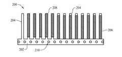
図2は、例示のバンドリア200を示す。この例示の実施形態では、バンドリア200は、帯202と、帯202から延びる複数のフィンガまたはリブ204とを含む。本明細書でスリーブ206と称される熱収縮チューブスリーブ206は、バンドリア200に結合し、リブ204を取り囲む。図2に示すように、スリーブ206は、第1の位置、すなわち初期位置でリブ204に結合する。説明の目的で、リブ204に対して第2の位置、すなわち除去位置にある複数のスリーブ208も図2に示す。例示の実施形態では、スリーブ206の初期位置は、帯202に隣接し、スリーブ208の除去位置は、帯202からある距離離れている。他の実施形態では、初期位置は、帯202から間隔があけられていてもよく、除去位置は、初期位置よりも、帯202に近くても遠くてもよい。帯202は、帯の中に画定された複数の開口210を含む。例示の実施形態では、開口210は、以下により詳細に説明するように、牽引車輪(図2では不図示)による係合のため、帯202の全域で、等距離に離間する。あるいは、開口210は、別々に位置し、かつ/または離間していてもよい。いくつかの実施形態では、バンドリア200は、帯202の反対側に、リブ204に接続した第2の帯も含んでもよく、かつ/または、リブ204があるまたはなしのスリーブ206によって互いに結合した2つの帯を含んでもよい。たとえば、図7は、複数のスリーブ206が、たとえば接着材、テープなどでもよい接合具502で2つの帯202に結合した例示のバンドリア500を示す。 FIG. 2 shows an
スリーブ206は、バンドリア200が作製、製造、組立てなどされるときに、リブ204上に初期位置で結合される。より具体的には、スリーブ206は、スリーブ206とリブ204の間に比較的強い摩擦接合が形成されるように、リブ204に対して、スリーブ206を部分的に熱収縮することによって、リブ204に結合される。図2は、除去位置にある数個のスリーブ208を示すが、初めに組み立てられるとき、バンドリア200は、通常、初期位置にあるリブ204のみと結合したスリーブ206を含む。スリーブ206が、リブ204にしっかりと結合した後、組み立てられたバンドリア200は、使える状態になる。例示の実態形態では、印刷機(図示せず)は、バンドリア200に結合したスリーブ206上に関連情報を印刷する。他の実施形態では、バンドリア200は、絶縁目的など、スリーブ206の印刷された情報を含むことなく、使用してもよい。 The
ワイヤハーネス(図示せず)のワイヤ(図示せず)を識別するなど、スリーブ206を使用するために、スリーブ206は、一般に、バンドリア200、より具体的にはリブ204から取り外される。スリーブ206を取り外すためには、スリーブ206とリブ204の間の摩擦接合を阻害し、破壊し、解除などしなければならない。例示の実施形態では、この解除は、例示の装置100によって容易に成し遂げられる。 In order to use the
動作中、供給システム102は、バンドリア200に係合し、バンドリア200を装置100の中に押し込む。供給システム102は、たとえば、牽引車輪、コンベヤベルト、移動締結システム、および/またはシュートシステムなどのバンドリア200に係合するなんらかの適切な方法によって、バンドリア200に係合してもよい。例示の実施形態では、供給システム102は、バンドリア200に係合する牽引車輪(図1では不図示)を含む。例示の牽引車輪300を図3に示す。牽引車輪300は、外側に放射状に延びる複数のピン304を含む中央車輪302を含む。ピン304は、たとえばバンドリア200の帯202の開口210に係合するような大きさおよび間隔で構成されている。牽引車輪300は、その中心306の周りを回転可能である。したがって、牽引車輪300が回転すると、ピン304は、バンドリアの開口210に係合し、バンドリア200を、牽引車輪300の回転方向に引っ張る。牽引車輪300は、第1の方向、すなわち前方向に回転すると、バンドリア200を除去システム104に推し進める。牽引車輪は、第2の方向、すなわち後方向に回転すると、バンドリア200を除去システム104から離れる方に推し進める。例示の実施形態では、牽引車輪300は、電機モータ(図3では不図示)によって回転する。他の実施形態では、牽引車輪300は、たとえば、非電気モータ、手回しクランクなどにより駆動されてもよい。他の実施形態では、供給システム102は、ピン304を含まない牽引車輪を含んでもよい。たとえば、いくつかの実施形態では、牽引車輪は、真空圧を用いて、バンドリア200に係合してもよく、または摩擦力に頼ってバンドリア200に係合してもよい。いくつかの実施形態では、供給システム102は、牽引車輪300を含まず、シュートシステム、ベルトシステム、移動クランプなど、バンドリア200に係合する異なる方法を利用してもよい。 In operation, the
バンドリア200が除去システム104内に推し進められると、除去システム104は、スリーブ206を、初期位置から、スリーブ208の除去位置へ除去する。例示の実施形態では、除去システム104は、駆動したピンチローラを各スリーブ206が通過する際に各スリーブ206に接触し、リブ204の長手方向に離脱力を及ぼすピンチローラシステム(図1では不図示)を含む。この力は、各スリーブ206を、初期位置からスリーブ208の除去位置へ動かす。スリーブ206を、スリーブ208の位置へ除去することによって、スリーブ206の部分的な熱収縮によって形成されたスリーブ206とリブ204の間の接合は、解除され、スリーブ206は、リブ204から容易に取り外され得る。例示の実施形態では、除去システム104は、スリーブ206を、リブ204から完全に取り外さず、ただスリーブ206を、スリーブ208の除去位置へ移動させる。他の実施形態では、除去システムは、スリーブ206を、図2に示すより大きなまたは小さな距離除去してもよく、かつ/または、スリーブ206を、リブ204から完全に取り外してもよい。他の実施形態では、除去システム104は、スリーブ206を、初期位置から除去するのに適したその他の任意のシステムを用いてもよい。たとえば、除去システム104は、連続して流れる圧縮空気、または一陣の圧縮空気を利用して、スリーブ206を除去してもよく、くさび形のプラウを利用して、スリーブ206を除去してもよく、かつ/または自動ピンセットおよび/またはプライヤを使用してスリーブ206を除去してもよい。図7に示す例示のバンドリア500などの2つの帯を有するバンドリアを使用すると、バンドリア500は、一巡ごと帯202の異なる方に係合する状態で、装置100に2回供給されてもよい。一巡ごと、次に牽引車輪300によって係合される帯202に対して、スリーブ206が除去される。 As the band rear 200 is advanced into the
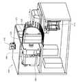
図4および図5は、ピンチローラシステム414を用いて、バンドリア200または500などのバンドリアのリブ204などのリブに結合したスリーブ206などのチューブスリーブを解除するのに用いることができる例示の装置400を示す。図6は、ピンチローラシステム414の単純化した上面図である。 FIGS. 4 and 5 illustrate an
例示の実施形態では、装置400は、供給システム402および除去システム404を含む。供給システム402は、モータ406およびギアボックス408に結合した牽引車輪300を含む。例示の実施形態では、モータ406は、ギアボックス408を介して、牽引車輪300の回転を駆動する。他の実施形態では、牽引車輪300は、モータ406によって直接駆動されてもよい。ハウジング410および牽引車輪300は、協働して、バンドリア200が、牽引車輪300によって推し進められるときに進むチャネル412を画定する。牽引車輪300の回転速度は、装置400を通してバンドリア200を処理する速度(すなわち、スリーブ206をバンドリア200から除去する速度)を制御する。例示の実施形態では、モータ406の速度、すなわち牽引車輪300の速度は、使用者によって可変的に制御されてもよい。他の実施形態では、牽引車輪300の速度は固定されていてもよく、または制御器(図示せず)によって可変的に制御されてもよい。 In the exemplary embodiment,
例示の実施形態では、除去システム404は、ピンチローラシステム414と、ピンチローラシステム414に結合したモータ416とを含む。ピンチローラシステム414は、軸422周りを回転する第1のピンチローラ418および軸424周りを回転する第2のピンチローラ420を含む。例示の実施形態では、第1のピンチローラ418は、モータ416に結合し、モータ416によって駆動され、一方、ピンチローラ420は、軸424の周りを自在に回転する受動ローラである。他の実施形態では、第2のピンチローラ420が、モータ416または別のモータによって駆動されてもよい。例示の実施形態では、ピンチローラ418は、一定の速度で回転し、スリーブ206が除去されるリブ204沿いの距離は、第1のピンチローラ418の直径によって確定される。いくつかの実施形態では、様々な直径のピンチローラを用いて、様々なスリーブ206除去量を作り出してもよい。他の実施形態では、ピンチローラ418の回転速度を、手動でまたは自動で変化させて、スリーブ206を除去する量を変化させてもよい。 In the exemplary embodiment,
動作中、使用者(図示せず)は、ハウジング部分426および428によって画定された斜面425上にバンドリア200を配置する。バンドリア200は、牽引車輪300、具体的にはピン304がバンドリア200に係合するまで、チャネル412に向かって、使用者によって移動される。牽引車輪300は、モータ406によって回転され、牽引車輪300は、バンドリア200を装置400内に推し進める。反転スイッチ430は、使用者が、牽引車輪300の回転を選択的に反転し、そうしてバンドリア200の動きを反転する(たとえば、バンドリア200を取り外す)ことを可能にする。牽引車輪300が回転すると、バンドリア200は、チャネル412に引き込まれ、ピンチローラシステム414に向かう。 In operation, a user (not shown) places the band rear 200 on the
図6に示すように、バンドリア200がピンチローラシステム414の中に推し進められると、連続スリーブ206は、ピンチローラ418と420の間に押し入れられる。ピンチローラ418の駆動された回転は、各スリーブ206に方向Aの力を及ぼす。バンドリアの帯202が、ピン304によって、牽引車輪300に対して実質的に固定された位置にとどまるので、スリーブ206に及ぼされた力は、スリーブ206を、方向Aに沿って牽引車輪300から、したがって帯202から離す。したがって、ピンチローラシステム414は、スリーブ206を、初期位置からスリーブ208の除去位置に除去し(図2に示す)、スリーブ206のバンドリア200からの取外しを可能にする。 As shown in FIG. 6, when the band rear 200 is pushed into the
したがって、例示の実施形態は、熱収縮チューブスリーブをバンドリアから取り外すいくつかの既知の方法と比較して、スリーブのバンドリアからのより迅速な取外しを可能にすることができる。さらに、例示の実施形態は、既知の手動の取外し方法と比較して、使用者にとって、より人間工学的であり得る。そのような実施形態は、反復動作による傷害の発生を減らす助けになり得る。よって、明細書に記載された例示の実施形態は、労働者の生産性を改善し、組み立てのコストを減らし、かつ/または反復動作に関連する傷害を減らし得る。 Thus, the exemplary embodiment can allow for quicker removal of the sleeve from the band rear as compared to some known methods of removing the heat shrink tube sleeve from the band rear. Furthermore, the exemplary embodiment may be more ergonomic for the user compared to known manual removal methods. Such an embodiment may help reduce the occurrence of injury due to repetitive motion. Thus, the exemplary embodiments described herein may improve worker productivity, reduce assembly costs, and / or reduce injury associated with repetitive operations.
この明細書は、例を用いて、最良の形態を含む様々な実施形態を開示し、当業者が、装置またはシステムを作り使用することおよび組み込まれた方法を行うことを含むこれらの実施形態を実行することを可能にする。特許可能な範囲は、特許請求の範囲によって定義され、当業者が思いつく他の例を含んでもよい。そのような他の例は、特許請求の範囲の文言と異ならない構造要素を有する場合、または、特許請求の範囲の文言とごくわずかしか異なっていない同等の構造要素を含む場合、特許請求の範囲内であることが意図されている。 This specification discloses, by way of example, various embodiments, including the best mode, and those skilled in the art will include these embodiments, including making and using devices or systems and performing integrated methods. Make it possible to execute. The patentable scope is defined by the claims, and may include other examples that occur to those skilled in the art. If such other examples have structural elements that do not differ from the language of the claims, or include equivalent structural elements that are only slightly different from the language of the claims, the claims Is intended to be within.
102 供給システム
104 除去システム
200 バンドリア
202 帯
204 リブ
206 チューブスリーブ
208 スリーブ
210 開口
300 牽引車輪
302 中央車輪
304 ピン
306 牽引車輪の中心
400 装置
402 供給システム
404 除去システム
406 モータ
408 ギアボックス
410 ハウジング
412 チャネル
414 ピンチローラシステム
416 モータ
418 第1のピンチローラ
420 第2のピンチローラ
422 軸
424 軸
425 斜面
426 ハウジング
428 ハウジング
500 バンドリア
502 接合具102
Claims (10)
Translated fromJapaneseバンドリア(200)に係合し、前記バンドリア(200)を、前記装置に選択的に配置するように構成された供給システム(102)であって、前記供給システム(102)はハウジング(410)および牽引車輪(300)を備え、前記ハウジング(410)と前記牽引車輪(300)の間に前記バンドリア(200)が推し進められるチャネル(412)を画定されている、供給システム(102)と、
前記供給システム(102)により前記チャネル(412)を介して推し進められる前記バンドリア(200)からチューブスリーブ(206)を除去するように構成された除去システム(104)であって、前記除去システム(104)は前記バンドリア(200)の前記除去システム(104)への供給に合わせて連続して処理するように構成され、前記除去システム(104)はさらに前記供給システム(102)によって推し進められたバンドリア(200)上の初期設置位置から前記チューブスリーブ(206)を除去するように構成された、除去システム(104)とを含む装置。An apparatus (100) used to release a tube sleeve (206) coupled to a band rear (200), comprising:
A supply system (102) configured to engage a band rear (200) and selectively place the band rear (200) on the device, the supply system (102) comprising a housing (410) and comprises a tractionwheel (300), wherein between the housing (410) and said tractionwheels (300) bandolier (200) is defining a channel (412) to be promoted, a supply system (102),
A removal system (104) configured to remove a tube sleeve (206) from the band rear (200) driven by the supply system (102) through the channel (412), the removal system (104) ) Is configured to continuously process the supply of the band rear (200) to the removal system (104), and the removal system (104) is further driven by the supply system (102). 200) a removal system (104) configured to remove said tube sleeve (206) from its initial installation position on.
バンドリア(200)を供給車輪に係合すること、
前記供給車輪を用いて、前記バンドリア(200)を除去システム(104)内に推し進めることであって、前記バンドリア(200)が前記供給車輪とハウジング(410)の間に画定されるチャネル(412)を介して推し進められる、推し進めること、および
チューブスリーブ(206)を前記除去システム(104)によって前記バンドリア(200)から除去することであって、前記除去システム(104)は前記バンドリア(200)の前記除去システム(104)への供給に合わせて連続して処理するように構成され、前記除去システム(104)はさらに前記除去システム(104)によって前記バンドリア(200)上の初期位置から前記チューブスリーブ(206)を除去するように構成された、除去することを含む方法。A method of releasing a tube sleeve (206) coupled to a band rear (200), comprising:
Engaging the band rear (200) to the supply wheel;
Using the supply wheel to drive the band rear (200) into a removal system (104), the channel (412) defined by the band rear (200) between the supply wheel and the housing (410). And removing the tube sleeve (206) from the band rear (200) by the removal system (104), wherein the removal system (104) is the said of the band rear (200). The removal system (104) is further configured to process continuously with supply to a removal system (104), and the removal system (104) is further moved from the initial position on the band rear (200) by the removal system (104) to the tube sleeve ( 206) configured to remove, including removing Law.
チューブスリーブ(206)を、前記一対のピンチローラ(418、420)の間で受け取ること、および
前記一対のピンチローラ(418、420)の少なくとも一方のピンチローラを駆動して回転させることを含み、前記一対のピンチローラ(418、420)の回転方向が前記供給車輪の回転方向に垂直である、請求項9に記載の方法。Removing the tube sleeve (206) from its initial position,
Receiving a tube sleeve (206) between the pair of pinch rollers (418, 420) and driving and rotating at least one pinch roller of the pair of pinch rollers (418, 420); The method according to claim 9, wherein the rotation direction of the pair of pinch rollers (418, 420) is perpendicular to the rotation direction of the supply wheel.
Applications Claiming Priority (2)
| Application Number | Priority Date | Filing Date | Title |
|---|---|---|---|
| US13/227,593US8935842B2 (en) | 2011-09-08 | 2011-09-08 | Sleeve removal device |
| US13/227,593 | 2011-09-08 |
Publications (2)
| Publication Number | Publication Date |
|---|---|
| JP2013243102A JP2013243102A (en) | 2013-12-05 |
| JP6106385B2true JP6106385B2 (en) | 2017-03-29 |
Family
ID=47172256
Family Applications (1)
| Application Number | Title | Priority Date | Filing Date |
|---|---|---|---|
| JP2012196906AActiveJP6106385B2 (en) | 2011-09-08 | 2012-09-07 | Sleeve removal device |
Country Status (5)
| Country | Link |
|---|---|
| US (1) | US8935842B2 (en) |
| EP (1) | EP2568478B1 (en) |
| JP (1) | JP6106385B2 (en) |
| BR (1) | BR102012022557B1 (en) |
| CA (1) | CA2788232C (en) |
Families Citing this family (9)
| Publication number | Priority date | Publication date | Assignee | Title |
|---|---|---|---|---|
| US10220535B2 (en) | 2011-09-08 | 2019-03-05 | The Boeing Company | Systems and methods of separating tubing sleeves from a tubing holder |
| US10226877B1 (en)* | 2011-09-08 | 2019-03-12 | The Boeing Company | Systems and methods of separating tubing sleeves from a tubing holder |
| US9944422B2 (en) | 2014-04-04 | 2018-04-17 | Brady Worldwide, Inc. | Sleeve applicator machine and related method of operation |
| US10279384B2 (en) | 2015-07-23 | 2019-05-07 | Ford Motor Company | Device for scraping debris from metal wire |
| CN105416649B (en)* | 2015-11-26 | 2017-12-05 | 温州聚龙知识产权有限公司 | One kind dress sheath machine |
| CN106057367A (en)* | 2016-05-13 | 2016-10-26 | 安庆市峰邦工业产品设计有限公司 | Large wire harness sleeving special-purpose device |
| US10569399B1 (en) | 2017-11-03 | 2020-02-25 | Brady Worldwide, Inc. | Wire sleeve hand application tool |
| US11872676B2 (en)* | 2021-05-21 | 2024-01-16 | Hubei Xianting Technology Co., Ltd. | Extraction device for heating tracer |
| CN113829300B (en)* | 2021-11-02 | 2022-11-22 | 四川奥尔铂电梯有限公司 | Drag guide wheel assembling device |
Family Cites Families (25)
| Publication number | Priority date | Publication date | Assignee | Title |
|---|---|---|---|---|
| US1969696A (en)* | 1933-03-30 | 1934-08-07 | Collins & Aikman Corp | Measuring device for yarn winding machines and the like |
| US3180442A (en)* | 1962-08-20 | 1965-04-27 | Neil G Pomeroy | Floating drive for boat sleds |
| SE305634B (en)* | 1964-08-19 | 1968-11-04 | Atlas Copco Ab | |
| US3312053A (en)* | 1965-02-19 | 1967-04-04 | Takamune Hirotoki | Step by step drvie mechanism for timepiece |
| US3522971A (en)* | 1967-11-15 | 1970-08-04 | Dale Corp Van | Drive wheel |
| US3894731A (en)* | 1973-06-14 | 1975-07-15 | Raychem Corp | Marker assembly |
| US4034450A (en)* | 1975-05-15 | 1977-07-12 | Raychem Corporation | Marker sleeve installation |
| US4083268A (en)* | 1976-12-21 | 1978-04-11 | O.K. Machine And Tool Corporation | Electrical wire dispenser with cutter and stripper |
| JPS583323B2 (en)* | 1979-06-28 | 1983-01-20 | 三菱重工業株式会社 | Wire identification sleeve extraction device |
| US4451965A (en)* | 1980-01-23 | 1984-06-05 | Raychem Corporation | Method for installing a sleeve on a substrate |
| US4365400A (en)* | 1980-01-23 | 1982-12-28 | Raychem Corporation | Apparatus for installing sleeves on substrates |
| US4655129A (en)* | 1985-10-11 | 1987-04-07 | W. H. Brady Co. | Marker sleeve processing machine |
| JPH0545057Y2 (en) | 1986-03-17 | 1993-11-17 | ||
| US4865895A (en)* | 1987-06-17 | 1989-09-12 | Raychem Corporation | Marker sleeve assembly |
| US4868023A (en)* | 1987-10-02 | 1989-09-19 | Raychem Corporation | Polyolefin article having permanent indicia thereon |
| US5021111A (en)* | 1988-08-31 | 1991-06-04 | Minnesota Mining And Manufacturing Company | Apparatus and method for applying heat-sensitive adhesive tape to a web moving at high speed |
| US5110638A (en)* | 1990-03-20 | 1992-05-05 | Raychem Corporation | Marker device with permanent indicia |
| US5865085A (en)* | 1995-05-12 | 1999-02-02 | Vollenweider; Eric | High volume wire stripper |
| JPH10199348A (en)* | 1997-01-16 | 1998-07-31 | Japan Automat Mach Co Ltd | Mark tube insertion device |
| US6089125A (en)* | 1999-08-27 | 2000-07-18 | Cheng; Yin-Ho | Combination wire stripper |
| US6334253B1 (en)* | 2000-08-28 | 2002-01-01 | Yin-Ho Cheng | Adjustable wire stripper |
| ITVR20020059A1 (en)* | 2002-05-24 | 2003-11-24 | Marziano Salvaro | BAG FOR VACUUM PACKAGING |
| US6875304B2 (en)* | 2003-04-17 | 2005-04-05 | Brady Worldwide, Inc. | Label applicator |
| US7469736B2 (en)* | 2003-04-22 | 2008-12-30 | Hellermanntyton Corporation | Label applicator |
| DE502006001891D1 (en)* | 2006-04-29 | 2008-12-04 | Mato Masch & Metallwaren | Device for separating cover layers from one end of a conveyor belt |
- 2011
- 2011-09-08USUS13/227,593patent/US8935842B2/enactiveActive
- 2012
- 2012-08-29CACA2788232Apatent/CA2788232C/enactiveActive
- 2012-09-05EPEP12183063.2Apatent/EP2568478B1/enactiveActive
- 2012-09-06BRBR102012022557Apatent/BR102012022557B1/enactiveIP Right Grant
- 2012-09-07JPJP2012196906Apatent/JP6106385B2/enactiveActive
Also Published As
| Publication number | Publication date |
|---|---|
| CA2788232A1 (en) | 2013-03-08 |
| US20130061443A1 (en) | 2013-03-14 |
| BR102012022557B1 (en) | 2020-05-05 |
| CA2788232C (en) | 2019-06-04 |
| US8935842B2 (en) | 2015-01-20 |
| JP2013243102A (en) | 2013-12-05 |
| BR102012022557A2 (en) | 2014-12-02 |
| EP2568478B1 (en) | 2016-06-29 |
| EP2568478A3 (en) | 2015-07-01 |
| EP2568478A2 (en) | 2013-03-13 |
Similar Documents
| Publication | Publication Date | Title |
|---|---|---|
| JP6106385B2 (en) | Sleeve removal device | |
| JP6495935B2 (en) | Foil removal device and method for removing foil from a tire tread | |
| EP3483075B1 (en) | Ahand-held automatic apparatus for fitting clamping collars | |
| CN108155606A (en) | Device and method for removing the sheath of an electrical conductor | |
| US12090784B2 (en) | Wheel holder | |
| US10017884B2 (en) | Coated cable for a conveyor system | |
| US6073916A (en) | Powered cable feeding system | |
| KR101531314B1 (en) | Incision roller for cable coating and cable coating stripper using the same | |
| EP0814921A1 (en) | Automatic drawing device | |
| CA2922741C (en) | Apparatus for changing paper rollers of a labelling machine and corresponding method for changing paper rolls | |
| JP2004141891A (en) | Pipe bender and method for bending pipe | |
| KR20150012458A (en) | Stripping device for cable coating and cable coating stripper using the same | |
| RU2006114774A (en) | EPILATOR | |
| KR101882470B1 (en) | Removal machine of release paper | |
| US20150231792A1 (en) | Systems and methods of separating tubing sleeves from a tubing holder | |
| EP0053562A1 (en) | Apparatus for feeding laundry pieces, particularly to an ironing machine | |
| JP4996630B2 (en) | Folding machine with signature removal and deceleration process | |
| JP5816875B2 (en) | Coated wire separation processing equipment | |
| JP2934418B2 (en) | Wire stripper | |
| US10226877B1 (en) | Systems and methods of separating tubing sleeves from a tubing holder | |
| CN104389967B (en) | Mechanical multi-level output mechanism and its application | |
| JP2003219737A (en) | Sheet recovering machine | |
| JPH05335167A (en) | Device and method for removing covering member from covered socket produced attendant to manufacture of magnet roll | |
| JPS60185608A (en) | Automatic tire chain attaching/detaching device with operational lever | |
| JP2007098763A (en) | Peeling method of ductile strip from mold release sheet and apparatus used therein |
Legal Events
| Date | Code | Title | Description |
|---|---|---|---|
| A621 | Written request for application examination | Free format text:JAPANESE INTERMEDIATE CODE: A621 Effective date:20150902 | |
| A977 | Report on retrieval | Free format text:JAPANESE INTERMEDIATE CODE: A971007 Effective date:20160629 | |
| A131 | Notification of reasons for refusal | Free format text:JAPANESE INTERMEDIATE CODE: A131 Effective date:20160705 | |
| A521 | Request for written amendment filed | Free format text:JAPANESE INTERMEDIATE CODE: A523 Effective date:20161005 | |
| A131 | Notification of reasons for refusal | Free format text:JAPANESE INTERMEDIATE CODE: A131 Effective date:20161025 | |
| A521 | Request for written amendment filed | Free format text:JAPANESE INTERMEDIATE CODE: A523 Effective date:20170123 | |
| TRDD | Decision of grant or rejection written | ||
| A01 | Written decision to grant a patent or to grant a registration (utility model) | Free format text:JAPANESE INTERMEDIATE CODE: A01 Effective date:20170207 | |
| A61 | First payment of annual fees (during grant procedure) | Free format text:JAPANESE INTERMEDIATE CODE: A61 Effective date:20170306 | |
| R150 | Certificate of patent or registration of utility model | Ref document number:6106385 Country of ref document:JP Free format text:JAPANESE INTERMEDIATE CODE: R150 | |
| R250 | Receipt of annual fees | Free format text:JAPANESE INTERMEDIATE CODE: R250 | |
| R250 | Receipt of annual fees | Free format text:JAPANESE INTERMEDIATE CODE: R250 | |
| R250 | Receipt of annual fees | Free format text:JAPANESE INTERMEDIATE CODE: R250 | |
| R250 | Receipt of annual fees | Free format text:JAPANESE INTERMEDIATE CODE: R250 | |
| R250 | Receipt of annual fees | Free format text:JAPANESE INTERMEDIATE CODE: R250 | |
| R250 | Receipt of annual fees | Free format text:JAPANESE INTERMEDIATE CODE: R250 |