JP6104353B2 - Surgical system instrument mounting - Google Patents
Surgical system instrument mountingDownload PDFInfo
- Publication number
- JP6104353B2 JP6104353B2JP2015233121AJP2015233121AJP6104353B2JP 6104353 B2JP6104353 B2JP 6104353B2JP 2015233121 AJP2015233121 AJP 2015233121AJP 2015233121 AJP2015233121 AJP 2015233121AJP 6104353 B2JP6104353 B2JP 6104353B2
- Authority
- JP
- Japan
- Prior art keywords
- instrument
- manipulator
- surgical instrument
- surgical
- distal end
- Prior art date
- Legal status (The legal status is an assumption and is not a legal conclusion. Google has not performed a legal analysis and makes no representation as to the accuracy of the status listed.)
- Active
Links
- 230000007246mechanismEffects0.000claimsdescription146
- 238000003780insertionMethods0.000claimsdescription71
- 230000037431insertionEffects0.000claimsdescription71
- 230000005540biological transmissionEffects0.000claimsdescription41
- 238000000034methodMethods0.000claimsdescription25
- 230000033001locomotionEffects0.000description115
- 239000012636effectorSubstances0.000description52
- 238000003384imaging methodMethods0.000description33
- 238000001356surgical procedureMethods0.000description29
- 210000000707wristAnatomy0.000description22
- 230000006835compressionEffects0.000description13
- 238000007906compressionMethods0.000description13
- 239000012528membraneSubstances0.000description12
- 238000005457optimizationMethods0.000description11
- 238000005096rolling processMethods0.000description11
- 238000010586diagramMethods0.000description9
- 230000006870functionEffects0.000description9
- 230000008901benefitEffects0.000description8
- 230000008878couplingEffects0.000description8
- 238000010168coupling processMethods0.000description8
- 238000005859coupling reactionMethods0.000description8
- 210000002414legAnatomy0.000description8
- 230000009471actionEffects0.000description7
- 230000000712assemblyEffects0.000description7
- 238000000429assemblyMethods0.000description7
- 210000001015abdomenAnatomy0.000description6
- 238000002432robotic surgeryMethods0.000description6
- 230000001954sterilising effectEffects0.000description6
- 238000004659sterilization and disinfectionMethods0.000description6
- 210000001519tissueAnatomy0.000description6
- 238000013519translationMethods0.000description6
- 238000005452bendingMethods0.000description5
- 230000008569processEffects0.000description5
- 241001631457CannulaSpecies0.000description4
- 210000000988bone and boneAnatomy0.000description4
- 238000013461designMethods0.000description4
- 239000000835fiberSubstances0.000description4
- 239000000463materialSubstances0.000description4
- 230000003287optical effectEffects0.000description4
- 238000012084abdominal surgeryMethods0.000description3
- 230000007547defectEffects0.000description3
- 230000000694effectsEffects0.000description3
- 238000005286illuminationMethods0.000description3
- 230000036512infertilityEffects0.000description3
- 239000013307optical fiberSubstances0.000description3
- 238000003860storageMethods0.000description3
- 229910000831SteelInorganic materials0.000description2
- 210000003484anatomyAnatomy0.000description2
- 239000003831antifriction materialSubstances0.000description2
- 230000004888barrier functionEffects0.000description2
- 230000008859changeEffects0.000description2
- 238000006243chemical reactionMethods0.000description2
- 150000001875compoundsChemical class0.000description2
- 238000002594fluoroscopyMethods0.000description2
- 125000001475halogen functional groupChemical group0.000description2
- 208000014674injuryDiseases0.000description2
- 239000000314lubricantSubstances0.000description2
- 210000001165lymph nodeAnatomy0.000description2
- 230000013011matingEffects0.000description2
- 229910052751metalInorganic materials0.000description2
- 239000002184metalSubstances0.000description2
- 238000002324minimally invasive surgeryMethods0.000description2
- 210000004197pelvisAnatomy0.000description2
- 230000036544postureEffects0.000description2
- 230000036316preloadEffects0.000description2
- 239000000523sampleSubstances0.000description2
- 239000010935stainless steelSubstances0.000description2
- 229910001220stainless steelInorganic materials0.000description2
- 239000010959steelSubstances0.000description2
- 230000008733traumaEffects0.000description2
- 238000002604ultrasonographyMethods0.000description2
- XUKUURHRXDUEBC-KAYWLYCHSA-NAtorvastatinChemical compoundC=1C=CC=CC=1C1=C(C=2C=CC(F)=CC=2)N(CC[C@@H](O)C[C@@H](O)CC(O)=O)C(C(C)C)=C1C(=O)NC1=CC=CC=C1XUKUURHRXDUEBC-KAYWLYCHSA-N0.000description1
- 241001589086Bellapiscis mediusSpecies0.000description1
- 229910000599Cr alloyInorganic materials0.000description1
- 230000005355Hall effectEffects0.000description1
- 208000027418Wounds and injuryDiseases0.000description1
- 230000003187abdominal effectEffects0.000description1
- 230000001154acute effectEffects0.000description1
- 210000004204blood vesselAnatomy0.000description1
- 210000001124body fluidAnatomy0.000description1
- 239000010839body fluidSubstances0.000description1
- 230000009172burstingEffects0.000description1
- 230000015556catabolic processEffects0.000description1
- 239000000788chromium alloySubstances0.000description1
- DYRBFMPPJATHRF-UHFFFAOYSA-Nchromium siliconChemical compound[Si].[Cr]DYRBFMPPJATHRF-UHFFFAOYSA-N0.000description1
- 230000001112coagulating effectEffects0.000description1
- 230000019771cognitionEffects0.000description1
- 230000008602contractionEffects0.000description1
- 238000007796conventional methodMethods0.000description1
- 230000006378damageEffects0.000description1
- 238000006731degradation reactionMethods0.000description1
- 238000001514detection methodMethods0.000description1
- 238000009826distributionMethods0.000description1
- 229940079593drugDrugs0.000description1
- 239000003814drugSubstances0.000description1
- 229920001746electroactive polymerPolymers0.000description1
- 239000003000extruded plasticSubstances0.000description1
- 230000008713feedback mechanismEffects0.000description1
- 230000005057finger movementEffects0.000description1
- 230000001939inductive effectEffects0.000description1
- 238000003973irrigationMethods0.000description1
- 230000002262irrigationEffects0.000description1
- 210000003127kneeAnatomy0.000description1
- 238000002357laparoscopic surgeryMethods0.000description1
- 238000002595magnetic resonance imagingMethods0.000description1
- 238000012423maintenanceMethods0.000description1
- 230000014759maintenance of locationEffects0.000description1
- 238000012986modificationMethods0.000description1
- 230000004048modificationEffects0.000description1
- 210000003205muscleAnatomy0.000description1
- 239000004033plasticSubstances0.000description1
- 229920003023plasticPolymers0.000description1
- 238000002360preparation methodMethods0.000description1
- 238000012545processingMethods0.000description1
- 238000011084recoveryMethods0.000description1
- 239000013643reference controlSubstances0.000description1
- 239000004065semiconductorSubstances0.000description1
- 230000035945sensitivityEffects0.000description1
- 230000001953sensory effectEffects0.000description1
- 230000001568sexual effectEffects0.000description1
- 229910001285shape-memory alloyInorganic materials0.000description1
- 238000010008shearingMethods0.000description1
- 239000000126substanceSubstances0.000description1
- 230000000451tissue damageEffects0.000description1
- 231100000827tissue damageToxicity0.000description1
- 238000012549trainingMethods0.000description1
- 230000009466transformationEffects0.000description1
- 210000003857wrist jointAnatomy0.000description1
Images


Classifications
- A—HUMAN NECESSITIES
- A61—MEDICAL OR VETERINARY SCIENCE; HYGIENE
- A61B—DIAGNOSIS; SURGERY; IDENTIFICATION
- A61B17/00—Surgical instruments, devices or methods
- A61B17/34—Trocars; Puncturing needles
- A61B17/3417—Details of tips or shafts, e.g. grooves, expandable, bendable; Multiple coaxial sliding cannulas, e.g. for dilating
- A61B17/3421—Cannulas
- A—HUMAN NECESSITIES
- A61—MEDICAL OR VETERINARY SCIENCE; HYGIENE
- A61B—DIAGNOSIS; SURGERY; IDENTIFICATION
- A61B34/00—Computer-aided surgery; Manipulators or robots specially adapted for use in surgery
- A61B34/70—Manipulators specially adapted for use in surgery
- A—HUMAN NECESSITIES
- A61—MEDICAL OR VETERINARY SCIENCE; HYGIENE
- A61B—DIAGNOSIS; SURGERY; IDENTIFICATION
- A61B1/00—Instruments for performing medical examinations of the interior of cavities or tubes of the body by visual or photographical inspection, e.g. endoscopes; Illuminating arrangements therefor
- A61B1/00131—Accessories for endoscopes
- A61B1/00135—Oversleeves mounted on the endoscope prior to insertion
- A—HUMAN NECESSITIES
- A61—MEDICAL OR VETERINARY SCIENCE; HYGIENE
- A61B—DIAGNOSIS; SURGERY; IDENTIFICATION
- A61B1/00—Instruments for performing medical examinations of the interior of cavities or tubes of the body by visual or photographical inspection, e.g. endoscopes; Illuminating arrangements therefor
- A61B1/00142—Instruments for performing medical examinations of the interior of cavities or tubes of the body by visual or photographical inspection, e.g. endoscopes; Illuminating arrangements therefor with means for preventing contamination, e.g. by using a sanitary sheath
- A—HUMAN NECESSITIES
- A61—MEDICAL OR VETERINARY SCIENCE; HYGIENE
- A61B—DIAGNOSIS; SURGERY; IDENTIFICATION
- A61B17/00—Surgical instruments, devices or methods
- A61B17/00234—Surgical instruments, devices or methods for minimally invasive surgery
- A—HUMAN NECESSITIES
- A61—MEDICAL OR VETERINARY SCIENCE; HYGIENE
- A61B—DIAGNOSIS; SURGERY; IDENTIFICATION
- A61B17/00—Surgical instruments, devices or methods
- A61B17/02—Surgical instruments, devices or methods for holding wounds open, e.g. retractors; Tractors
- A61B17/0218—Surgical instruments, devices or methods for holding wounds open, e.g. retractors; Tractors for minimally invasive surgery
- A—HUMAN NECESSITIES
- A61—MEDICAL OR VETERINARY SCIENCE; HYGIENE
- A61B—DIAGNOSIS; SURGERY; IDENTIFICATION
- A61B17/00—Surgical instruments, devices or methods
- A61B17/34—Trocars; Puncturing needles
- A61B17/3417—Details of tips or shafts, e.g. grooves, expandable, bendable; Multiple coaxial sliding cannulas, e.g. for dilating
- A61B17/3421—Cannulas
- A61B17/3423—Access ports, e.g. toroid shape introducers for instruments or hands
- A—HUMAN NECESSITIES
- A61—MEDICAL OR VETERINARY SCIENCE; HYGIENE
- A61B—DIAGNOSIS; SURGERY; IDENTIFICATION
- A61B17/00—Surgical instruments, devices or methods
- A61B17/34—Trocars; Puncturing needles
- A61B17/3474—Insufflating needles, e.g. Veress needles
- A—HUMAN NECESSITIES
- A61—MEDICAL OR VETERINARY SCIENCE; HYGIENE
- A61B—DIAGNOSIS; SURGERY; IDENTIFICATION
- A61B34/00—Computer-aided surgery; Manipulators or robots specially adapted for use in surgery
- A—HUMAN NECESSITIES
- A61—MEDICAL OR VETERINARY SCIENCE; HYGIENE
- A61B—DIAGNOSIS; SURGERY; IDENTIFICATION
- A61B34/00—Computer-aided surgery; Manipulators or robots specially adapted for use in surgery
- A61B34/30—Surgical robots
- A—HUMAN NECESSITIES
- A61—MEDICAL OR VETERINARY SCIENCE; HYGIENE
- A61B—DIAGNOSIS; SURGERY; IDENTIFICATION
- A61B34/00—Computer-aided surgery; Manipulators or robots specially adapted for use in surgery
- A61B34/30—Surgical robots
- A61B34/35—Surgical robots for telesurgery
- A—HUMAN NECESSITIES
- A61—MEDICAL OR VETERINARY SCIENCE; HYGIENE
- A61B—DIAGNOSIS; SURGERY; IDENTIFICATION
- A61B34/00—Computer-aided surgery; Manipulators or robots specially adapted for use in surgery
- A61B34/30—Surgical robots
- A61B34/37—Leader-follower robots
- A—HUMAN NECESSITIES
- A61—MEDICAL OR VETERINARY SCIENCE; HYGIENE
- A61B—DIAGNOSIS; SURGERY; IDENTIFICATION
- A61B46/00—Surgical drapes
- A61B46/10—Surgical drapes specially adapted for instruments, e.g. microscopes
- A—HUMAN NECESSITIES
- A61—MEDICAL OR VETERINARY SCIENCE; HYGIENE
- A61B—DIAGNOSIS; SURGERY; IDENTIFICATION
- A61B46/00—Surgical drapes
- A61B46/20—Surgical drapes specially adapted for patients
- A61B46/23—Surgical drapes specially adapted for patients with means to retain or hold surgical implements
- A—HUMAN NECESSITIES
- A61—MEDICAL OR VETERINARY SCIENCE; HYGIENE
- A61B—DIAGNOSIS; SURGERY; IDENTIFICATION
- A61B50/00—Containers, covers, furniture or holders specially adapted for surgical or diagnostic appliances or instruments, e.g. sterile covers
- A—HUMAN NECESSITIES
- A61—MEDICAL OR VETERINARY SCIENCE; HYGIENE
- A61B—DIAGNOSIS; SURGERY; IDENTIFICATION
- A61B50/00—Containers, covers, furniture or holders specially adapted for surgical or diagnostic appliances or instruments, e.g. sterile covers
- A61B50/20—Holders specially adapted for surgical or diagnostic appliances or instruments
- A—HUMAN NECESSITIES
- A61—MEDICAL OR VETERINARY SCIENCE; HYGIENE
- A61B—DIAGNOSIS; SURGERY; IDENTIFICATION
- A61B50/00—Containers, covers, furniture or holders specially adapted for surgical or diagnostic appliances or instruments, e.g. sterile covers
- A61B50/30—Containers specially adapted for packaging, protecting, dispensing, collecting or disposing of surgical or diagnostic appliances or instruments
- A—HUMAN NECESSITIES
- A61—MEDICAL OR VETERINARY SCIENCE; HYGIENE
- A61B—DIAGNOSIS; SURGERY; IDENTIFICATION
- A61B90/00—Instruments, implements or accessories specially adapted for surgery or diagnosis and not covered by any of the groups A61B1/00 - A61B50/00, e.g. for luxation treatment or for protecting wound edges
- A61B90/50—Supports for surgical instruments, e.g. articulated arms
- A—HUMAN NECESSITIES
- A61—MEDICAL OR VETERINARY SCIENCE; HYGIENE
- A61B—DIAGNOSIS; SURGERY; IDENTIFICATION
- A61B90/00—Instruments, implements or accessories specially adapted for surgery or diagnosis and not covered by any of the groups A61B1/00 - A61B50/00, e.g. for luxation treatment or for protecting wound edges
- A61B90/90—Identification means for patients or instruments, e.g. tags
- A61B90/98—Identification means for patients or instruments, e.g. tags using electromagnetic means, e.g. transponders
- A—HUMAN NECESSITIES
- A61—MEDICAL OR VETERINARY SCIENCE; HYGIENE
- A61M—DEVICES FOR INTRODUCING MEDIA INTO, OR ONTO, THE BODY; DEVICES FOR TRANSDUCING BODY MEDIA OR FOR TAKING MEDIA FROM THE BODY; DEVICES FOR PRODUCING OR ENDING SLEEP OR STUPOR
- A61M13/00—Insufflators for therapeutic or disinfectant purposes, i.e. devices for blowing a gas, powder or vapour into the body
- A61M13/003—Blowing gases other than for carrying powders, e.g. for inflating, dilating or rinsing
- B—PERFORMING OPERATIONS; TRANSPORTING
- B25—HAND TOOLS; PORTABLE POWER-DRIVEN TOOLS; MANIPULATORS
- B25J—MANIPULATORS; CHAMBERS PROVIDED WITH MANIPULATION DEVICES
- B25J15/00—Gripping heads and other end effectors
- B25J15/0052—Gripping heads and other end effectors multiple gripper units or multiple end effectors
- B25J15/0066—Gripping heads and other end effectors multiple gripper units or multiple end effectors with different types of end effectors, e.g. gripper and welding gun
- B—PERFORMING OPERATIONS; TRANSPORTING
- B25—HAND TOOLS; PORTABLE POWER-DRIVEN TOOLS; MANIPULATORS
- B25J—MANIPULATORS; CHAMBERS PROVIDED WITH MANIPULATION DEVICES
- B25J15/00—Gripping heads and other end effectors
- B25J15/04—Gripping heads and other end effectors with provision for the remote detachment or exchange of the head or parts thereof
- F—MECHANICAL ENGINEERING; LIGHTING; HEATING; WEAPONS; BLASTING
- F16—ENGINEERING ELEMENTS AND UNITS; GENERAL MEASURES FOR PRODUCING AND MAINTAINING EFFECTIVE FUNCTIONING OF MACHINES OR INSTALLATIONS; THERMAL INSULATION IN GENERAL
- F16F—SPRINGS; SHOCK-ABSORBERS; MEANS FOR DAMPING VIBRATION
- F16F1/00—Springs
- F16F1/02—Springs made of steel or other material having low internal friction; Wound, torsion, leaf, cup, ring or the like springs, the material of the spring not being relevant
- F16F1/04—Wound springs
- F16F1/12—Attachments or mountings
- F16F1/121—Attachments or mountings adjustable, e.g. to modify spring characteristics
- G—PHYSICS
- G03—PHOTOGRAPHY; CINEMATOGRAPHY; ANALOGOUS TECHNIQUES USING WAVES OTHER THAN OPTICAL WAVES; ELECTROGRAPHY; HOLOGRAPHY
- G03B—APPARATUS OR ARRANGEMENTS FOR TAKING PHOTOGRAPHS OR FOR PROJECTING OR VIEWING THEM; APPARATUS OR ARRANGEMENTS EMPLOYING ANALOGOUS TECHNIQUES USING WAVES OTHER THAN OPTICAL WAVES; ACCESSORIES THEREFOR
- G03B3/00—Focusing arrangements of general interest for cameras, projectors or printers
- G—PHYSICS
- G03—PHOTOGRAPHY; CINEMATOGRAPHY; ANALOGOUS TECHNIQUES USING WAVES OTHER THAN OPTICAL WAVES; ELECTROGRAPHY; HOLOGRAPHY
- G03B—APPARATUS OR ARRANGEMENTS FOR TAKING PHOTOGRAPHS OR FOR PROJECTING OR VIEWING THEM; APPARATUS OR ARRANGEMENTS EMPLOYING ANALOGOUS TECHNIQUES USING WAVES OTHER THAN OPTICAL WAVES; ACCESSORIES THEREFOR
- G03B35/00—Stereoscopic photography
- H—ELECTRICITY
- H01—ELECTRIC ELEMENTS
- H01F—MAGNETS; INDUCTANCES; TRANSFORMERS; SELECTION OF MATERIALS FOR THEIR MAGNETIC PROPERTIES
- H01F27/00—Details of transformers or inductances, in general
- H01F27/28—Coils; Windings; Conductive connections
- H01F27/2823—Wires
- H—ELECTRICITY
- H01—ELECTRIC ELEMENTS
- H01F—MAGNETS; INDUCTANCES; TRANSFORMERS; SELECTION OF MATERIALS FOR THEIR MAGNETIC PROPERTIES
- H01F5/00—Coils
- H01F5/02—Coils wound on non-magnetic supports, e.g. formers
- H—ELECTRICITY
- H01—ELECTRIC ELEMENTS
- H01F—MAGNETS; INDUCTANCES; TRANSFORMERS; SELECTION OF MATERIALS FOR THEIR MAGNETIC PROPERTIES
- H01F5/00—Coils
- H01F5/04—Arrangements of electric connections to coils, e.g. leads
- H—ELECTRICITY
- H04—ELECTRIC COMMUNICATION TECHNIQUE
- H04N—PICTORIAL COMMUNICATION, e.g. TELEVISION
- H04N23/00—Cameras or camera modules comprising electronic image sensors; Control thereof
- H04N23/50—Constructional details
- H04N23/51—Housings
- H—ELECTRICITY
- H04—ELECTRIC COMMUNICATION TECHNIQUE
- H04N—PICTORIAL COMMUNICATION, e.g. TELEVISION
- H04N23/00—Cameras or camera modules comprising electronic image sensors; Control thereof
- H04N23/50—Constructional details
- H04N23/54—Mounting of pick-up tubes, electronic image sensors, deviation or focusing coils
- H—ELECTRICITY
- H04—ELECTRIC COMMUNICATION TECHNIQUE
- H04N—PICTORIAL COMMUNICATION, e.g. TELEVISION
- H04N23/00—Cameras or camera modules comprising electronic image sensors; Control thereof
- H04N23/50—Constructional details
- H04N23/55—Optical parts specially adapted for electronic image sensors; Mounting thereof
- H—ELECTRICITY
- H04—ELECTRIC COMMUNICATION TECHNIQUE
- H04N—PICTORIAL COMMUNICATION, e.g. TELEVISION
- H04N23/00—Cameras or camera modules comprising electronic image sensors; Control thereof
- H04N23/50—Constructional details
- H04N23/555—Constructional details for picking-up images in sites, inaccessible due to their dimensions or hazardous conditions, e.g. endoscopes or borescopes
- H—ELECTRICITY
- H04—ELECTRIC COMMUNICATION TECHNIQUE
- H04N—PICTORIAL COMMUNICATION, e.g. TELEVISION
- H04N23/00—Cameras or camera modules comprising electronic image sensors; Control thereof
- H04N23/57—Mechanical or electrical details of cameras or camera modules specially adapted for being embedded in other devices
- H—ELECTRICITY
- H04—ELECTRIC COMMUNICATION TECHNIQUE
- H04N—PICTORIAL COMMUNICATION, e.g. TELEVISION
- H04N23/00—Cameras or camera modules comprising electronic image sensors; Control thereof
- H04N23/60—Control of cameras or camera modules
- H—ELECTRICITY
- H04—ELECTRIC COMMUNICATION TECHNIQUE
- H04N—PICTORIAL COMMUNICATION, e.g. TELEVISION
- H04N23/00—Cameras or camera modules comprising electronic image sensors; Control thereof
- H04N23/60—Control of cameras or camera modules
- H04N23/68—Control of cameras or camera modules for stable pick-up of the scene, e.g. compensating for camera body vibrations
- H04N23/682—Vibration or motion blur correction
- H04N23/685—Vibration or motion blur correction performed by mechanical compensation
- H04N23/687—Vibration or motion blur correction performed by mechanical compensation by shifting the lens or sensor position
- H—ELECTRICITY
- H05—ELECTRIC TECHNIQUES NOT OTHERWISE PROVIDED FOR
- H05K—PRINTED CIRCUITS; CASINGS OR CONSTRUCTIONAL DETAILS OF ELECTRIC APPARATUS; MANUFACTURE OF ASSEMBLAGES OF ELECTRICAL COMPONENTS
- H05K1/00—Printed circuits
- H05K1/18—Printed circuits structurally associated with non-printed electric components
- A—HUMAN NECESSITIES
- A61—MEDICAL OR VETERINARY SCIENCE; HYGIENE
- A61B—DIAGNOSIS; SURGERY; IDENTIFICATION
- A61B17/00—Surgical instruments, devices or methods
- A61B17/28—Surgical forceps
- A61B17/29—Forceps for use in minimally invasive surgery
- A—HUMAN NECESSITIES
- A61—MEDICAL OR VETERINARY SCIENCE; HYGIENE
- A61B—DIAGNOSIS; SURGERY; IDENTIFICATION
- A61B17/00—Surgical instruments, devices or methods
- A61B2017/00477—Coupling
- A—HUMAN NECESSITIES
- A61—MEDICAL OR VETERINARY SCIENCE; HYGIENE
- A61B—DIAGNOSIS; SURGERY; IDENTIFICATION
- A61B17/00—Surgical instruments, devices or methods
- A61B17/34—Trocars; Puncturing needles
- A61B17/3417—Details of tips or shafts, e.g. grooves, expandable, bendable; Multiple coaxial sliding cannulas, e.g. for dilating
- A61B17/3421—Cannulas
- A61B2017/3445—Cannulas used as instrument channel for multiple instruments
- A61B2017/3447—Linked multiple cannulas
- A—HUMAN NECESSITIES
- A61—MEDICAL OR VETERINARY SCIENCE; HYGIENE
- A61B—DIAGNOSIS; SURGERY; IDENTIFICATION
- A61B34/00—Computer-aided surgery; Manipulators or robots specially adapted for use in surgery
- A61B34/30—Surgical robots
- A61B2034/302—Surgical robots specifically adapted for manipulations within body cavities, e.g. within abdominal or thoracic cavities
- A—HUMAN NECESSITIES
- A61—MEDICAL OR VETERINARY SCIENCE; HYGIENE
- A61B—DIAGNOSIS; SURGERY; IDENTIFICATION
- A61B34/00—Computer-aided surgery; Manipulators or robots specially adapted for use in surgery
- A61B34/30—Surgical robots
- A61B2034/305—Details of wrist mechanisms at distal ends of robotic arms
- A61B2034/306—Wrists with multiple vertebrae
- A—HUMAN NECESSITIES
- A61—MEDICAL OR VETERINARY SCIENCE; HYGIENE
- A61B—DIAGNOSIS; SURGERY; IDENTIFICATION
- A61B50/00—Containers, covers, furniture or holders specially adapted for surgical or diagnostic appliances or instruments, e.g. sterile covers
- A61B50/30—Containers specially adapted for packaging, protecting, dispensing, collecting or disposing of surgical or diagnostic appliances or instruments
- A61B2050/3008—Containers specially adapted for packaging, protecting, dispensing, collecting or disposing of surgical or diagnostic appliances or instruments having multiple compartments
- A—HUMAN NECESSITIES
- A61—MEDICAL OR VETERINARY SCIENCE; HYGIENE
- A61B—DIAGNOSIS; SURGERY; IDENTIFICATION
- A61B90/00—Instruments, implements or accessories specially adapted for surgery or diagnosis and not covered by any of the groups A61B1/00 - A61B50/00, e.g. for luxation treatment or for protecting wound edges
- A61B90/50—Supports for surgical instruments, e.g. articulated arms
- A61B2090/5025—Supports for surgical instruments, e.g. articulated arms with a counter-balancing mechanism
- B—PERFORMING OPERATIONS; TRANSPORTING
- B25—HAND TOOLS; PORTABLE POWER-DRIVEN TOOLS; MANIPULATORS
- B25J—MANIPULATORS; CHAMBERS PROVIDED WITH MANIPULATION DEVICES
- B25J15/00—Gripping heads and other end effectors
- B25J15/02—Gripping heads and other end effectors servo-actuated
- B—PERFORMING OPERATIONS; TRANSPORTING
- B32—LAYERED PRODUCTS
- B32B—LAYERED PRODUCTS, i.e. PRODUCTS BUILT-UP OF STRATA OF FLAT OR NON-FLAT, e.g. CELLULAR OR HONEYCOMB, FORM
- B32B3/00—Layered products comprising a layer with external or internal discontinuities or unevennesses, or a layer of non-planar shape; Layered products comprising a layer having particular features of form
- B32B3/10—Layered products comprising a layer with external or internal discontinuities or unevennesses, or a layer of non-planar shape; Layered products comprising a layer having particular features of form characterised by a discontinuous layer, i.e. formed of separate pieces of material
- B32B3/12—Layered products comprising a layer with external or internal discontinuities or unevennesses, or a layer of non-planar shape; Layered products comprising a layer having particular features of form characterised by a discontinuous layer, i.e. formed of separate pieces of material characterised by a layer of regularly- arranged cells, e.g. a honeycomb structure
- G—PHYSICS
- G03—PHOTOGRAPHY; CINEMATOGRAPHY; ANALOGOUS TECHNIQUES USING WAVES OTHER THAN OPTICAL WAVES; ELECTROGRAPHY; HOLOGRAPHY
- G03B—APPARATUS OR ARRANGEMENTS FOR TAKING PHOTOGRAPHS OR FOR PROJECTING OR VIEWING THEM; APPARATUS OR ARRANGEMENTS EMPLOYING ANALOGOUS TECHNIQUES USING WAVES OTHER THAN OPTICAL WAVES; ACCESSORIES THEREFOR
- G03B2205/00—Adjustment of optical system relative to image or object surface other than for focusing
- G03B2205/0007—Movement of one or more optical elements for control of motion blur
- G03B2205/0015—Movement of one or more optical elements for control of motion blur by displacing one or more optical elements normal to the optical axis
- G—PHYSICS
- G03—PHOTOGRAPHY; CINEMATOGRAPHY; ANALOGOUS TECHNIQUES USING WAVES OTHER THAN OPTICAL WAVES; ELECTROGRAPHY; HOLOGRAPHY
- G03B—APPARATUS OR ARRANGEMENTS FOR TAKING PHOTOGRAPHS OR FOR PROJECTING OR VIEWING THEM; APPARATUS OR ARRANGEMENTS EMPLOYING ANALOGOUS TECHNIQUES USING WAVES OTHER THAN OPTICAL WAVES; ACCESSORIES THEREFOR
- G03B2205/00—Adjustment of optical system relative to image or object surface other than for focusing
- G03B2205/0053—Driving means for the movement of one or more optical element
- G03B2205/0069—Driving means for the movement of one or more optical element using electromagnetic actuators, e.g. voice coils
- G—PHYSICS
- G03—PHOTOGRAPHY; CINEMATOGRAPHY; ANALOGOUS TECHNIQUES USING WAVES OTHER THAN OPTICAL WAVES; ELECTROGRAPHY; HOLOGRAPHY
- G03B—APPARATUS OR ARRANGEMENTS FOR TAKING PHOTOGRAPHS OR FOR PROJECTING OR VIEWING THEM; APPARATUS OR ARRANGEMENTS EMPLOYING ANALOGOUS TECHNIQUES USING WAVES OTHER THAN OPTICAL WAVES; ACCESSORIES THEREFOR
- G03B5/00—Adjustment of optical system relative to image or object surface other than for focusing
- G03B5/02—Lateral adjustment of lens
- H—ELECTRICITY
- H01—ELECTRIC ELEMENTS
- H01F—MAGNETS; INDUCTANCES; TRANSFORMERS; SELECTION OF MATERIALS FOR THEIR MAGNETIC PROPERTIES
- H01F5/00—Coils
- H01F5/02—Coils wound on non-magnetic supports, e.g. formers
- H01F2005/027—Coils wound on non-magnetic supports, e.g. formers wound on formers for receiving several coils with perpendicular winding axes, e.g. for antennae or inductive power transfer
- Y—GENERAL TAGGING OF NEW TECHNOLOGICAL DEVELOPMENTS; GENERAL TAGGING OF CROSS-SECTIONAL TECHNOLOGIES SPANNING OVER SEVERAL SECTIONS OF THE IPC; TECHNICAL SUBJECTS COVERED BY FORMER USPC CROSS-REFERENCE ART COLLECTIONS [XRACs] AND DIGESTS
- Y10—TECHNICAL SUBJECTS COVERED BY FORMER USPC
- Y10T—TECHNICAL SUBJECTS COVERED BY FORMER US CLASSIFICATION
- Y10T74/00—Machine element or mechanism
- Y10T74/20—Control lever and linkage systems
- Y10T74/20207—Multiple controlling elements for single controlled element
- Y10T74/20305—Robotic arm
Landscapes
- Health & Medical Sciences (AREA)
- Life Sciences & Earth Sciences (AREA)
- Engineering & Computer Science (AREA)
- Surgery (AREA)
- Animal Behavior & Ethology (AREA)
- General Health & Medical Sciences (AREA)
- Biomedical Technology (AREA)
- Heart & Thoracic Surgery (AREA)
- Veterinary Medicine (AREA)
- Public Health (AREA)
- Medical Informatics (AREA)
- Molecular Biology (AREA)
- Nuclear Medicine, Radiotherapy & Molecular Imaging (AREA)
- Robotics (AREA)
- Pathology (AREA)
- Physics & Mathematics (AREA)
- Multimedia (AREA)
- Signal Processing (AREA)
- Mechanical Engineering (AREA)
- Oral & Maxillofacial Surgery (AREA)
- Power Engineering (AREA)
- Electromagnetism (AREA)
- General Engineering & Computer Science (AREA)
- Anesthesiology (AREA)
- Hematology (AREA)
- Biophysics (AREA)
- Optics & Photonics (AREA)
- Radiology & Medical Imaging (AREA)
- General Physics & Mathematics (AREA)
- Microelectronics & Electronic Packaging (AREA)
- Manipulator (AREA)
Description
Translated fromJapanese (関連出願の相互参照)
本出願は、2010年5月14日に出願された「Surgical System」という名称の米国仮特許出願第61/334,978号明細書の利益を主張し、該出願の全開示は、全ての目的のために、本明細書において参考により援用される。(Cross-reference of related applications)
This application claims the benefit of US Provisional Patent Application No. 61 / 334,978, filed May 14, 2010, entitled “Surgical System”, the entire disclosure of which is incorporated herein by reference for all purposes. For this purpose, incorporated herein by reference.
本出願は、2007年6月13日に出願された米国特許出願第11/762,165号明細書に関連し、該明細書は、全ての目的のために、本明細書において参考により援用される。米国特許出願第11/762,165号明細書は、次の複数の米国仮特許出願の優先権の利益を主張していて、それらの米国仮特許出願の全てが、本明細書において参考により援用される。それらの米国仮特許出願は、Cooper等による2006年6月13日に出願された「Single port system 2」という名称の米国仮特許出願第60/813,028号明細書、Cooperによる2006年6月13日に出願された「Single port surgical system 1」という名称の米国仮特許出願第60/813,029号明細書、Larkin等による2006年6月13日に出願された「Independently actuated optical train」という名称の米国仮特許出願第60/813,030号明細書、Larkin等による2006年6月13日に出願された「Modular cannula architecture」という名称の米国仮特許出願第60/813,075号明細書、Larkin等による2006年6月13日に出願された「Methods for delivering instruments to a surgical site with minimal disturbance to intermediate structures」という名称の米国仮特許出願第60/813,125号明細書、Cooperによる2006年6月13日に出願された「Rigid single port surgical system」という名称の米国仮特許出願第60/813,126号明細書、Cooper等による2006年6月13日に出願された「Minimum net force actuation」という名称の米国仮特許出願第60/813,129号明細書、Duval等による2006年6月13日に出願された「Side working tools and camera」という名称の米国仮特許出願第60/813,131号明細書、Cooperによる2006年6月13日に出願された「Passing cables through joints」という名称の米国仮特許出願第60/813,172号明細書、Larkin等による2006年6月13日に出願された「Hollow smoothly bending instrument joints」という名称の米国仮特許出願第60/813,173号明細書、Mohr等による2006年6月13日に出願された「Retraction devices and methods」という名称の米国仮特許出願第60/813,198号明細書、Diolaiti等による2006年6月13日に出願された「Sensory architecture for endoluminal robots」という名称の米国仮特許出願第60/813,207号明細書、及びMohr等による2006年6月13日に出願された「Concept for single port laparoscopic surgery」という名称の米国仮特許出願第60/813,328号明細書である。 This application is related to US patent application Ser. No. 11 / 762,165, filed Jun. 13, 2007, which is hereby incorporated by reference for all purposes. The US patent application Ser. No. 11 / 762,165 claims the benefit of priority of the following US provisional patent applications, all of which are hereby incorporated by reference. Is done. No. 60 / 813,028, entitled “Single port system 2” filed June 13, 2006 by Cooper et al., June 2006 by Cooper. U.S. Provisional Patent Application No. 60 / 813,029 entitled "Single port
更に、本出願は、次の複数の継続中の米国特許出願明細書に関連し、それらの全てが、本明細書において参考により援用される。それらの米国特許出願明細書は、Mohrによる「Retraction of tissue for single port entry, robotically assisted medical procedures」という名称の米国特許出願第11/762,217号明細書、Mohr等による「Bracing of bundled medical device for single port entry,robotically assisted medical procedures」という名称の米国特許出願第11/762,222号明細書、Schenaによる「Extendable suction surface for brasing medical devices during robotically assisted medical procedures」という名称の米国特許出願第11/762,231号明細書、Diolaiti等による「Control system configured to compensate for non−ideal actuator−to−joint linkage characteristics in a medical robotic system」という名称の米国特許出願第11/762,236号明細書、Cooper等による「Surgical instrument actuation system」という名称の米国特許出願第11/762,185号明細書、Cooper等による「Surgical instrument actuator」という名称の米国特許出願第11/762,172号明細書、Larkin等による「Minimally invasive surgical instrument advancement」という名称の米国特許出願第11/762,161号明細書、Cooper等による「Surgical instrument control and actuation」という名称の米国特許出願第11/762,158号明細書、Cooperによる「Surgical instrument with parallel motion mechanism」という名称の米国特許出願第11/762,154号明細書、Larkinによる「Minimally invasive surgical apparatus with side exit instruments」という名称の米国特許出願第11/762,149号明細書、Larkinによる「Minimally invasive surgical apparatus with side exit instruments」という名称の米国特許出願第11/762,170号明細書、Larkinによる「Minimally invasive surgical instrument system」という名称の米国特許出願第11/762,143号明細書、Cooper等による「Side looking minimally invasive surgery instrument assembly」という名称の米国特許出願第11/762,135号明細書、Cooper等による「Side looking minimally invasive surgery instrument assembly」という名称の米国特許出願第11/762,132号明細書、Larkin等による「Guide tube control of minimally invasive surgical instruments」という名称の米国特許出願第11/762,127号明細書、Larkin等による「Minimally invasive surgery guide tube」という名称の米国特許出願第11/762,123号明細書、Larkin等による「Minimally invasive surgery guide tube」という名称の米国特許出願第11/762,120号明細書、Larkinによる「Minimally invasive surgical retractor system」という名称の米国特許出願第11/762,118号明細書、Schena等による「Minimally invasive surgical illumination」という名称の米国特許出願第11/762,114号明細書、Duval等による「Retrograde instrument」という名称の米国特許出願第11/762,110号明細書、Duval等による「Retrograde instrument」という名称の米国特許出願第11/762,204号明細書、Larkinによる「Preventing instrument/tissue collisions」という名称の米国特許出願第11/762,202号明細書、Larkin等による「Minimally invasive surgery instrument assembly with reduced cross section」という名称の米国特許出願第11/762,189号明細書、Larkin等による「Minimally invasive surgical system」という名称の米国特許出願第11/762,191号明細書、Duval等による「Minimally invasive surgical system」という名称の米国特許出願第11/762,196号明細書、及びDiolaitiによる「Minimally invasive surgical system」という名称の米国特許出願第11/762,200号明細書である。 In addition, this application is related to the following plurality of pending US patent applications, all of which are hereby incorporated by reference: No. 11 / 762,217 of Modr et al., “Bracing of United States Patent Application No. 11 / 762,217 by Mohr et al. US patent application Ser. No. 11 / 762,222 entitled “For Single Portioned Medical, Robotic Assisted Medical Procedures”, “Extendable Succeeding Forcing Bursting Medicine” US Patent Application No. 11 / 762,231 entitled “Controlled to non-compacted-in-charge-in-the-store-in-the-store”. US patent application Ser. No. 11 / 762,236, US patent application Ser. No. 11 / 762,185 entitled “Surgical instrument act system” by Cooper et al., “Surgical instrument act” by Cooper et al. US patent application Ser. No. 11 / 762,172 entitled “Ator”; US Patent Application No. 11 / 762,161 entitled “Minimally Inverse Surgical Instrument Advancement” by Larkin et al., “Surgical instrument” by Cooper et al. US patent application Ser. No. 11 / 762,158 entitled “control and actuation”; US patent application No. 11 / 762,154 named “surgical instrument with parallel motion mechanism” by Cooper; “Minimal by Lakin” invasive surgical apprat US patent application Ser. No. 11 / 762,149 entitled “swith side exit instruments”; US Patent Application No. 11 / No. 11/170, patent application No. 11/170 entitled “Minimally invasive surgical apparatus”. US patent application Ser. No. 11 / 762,143 entitled “Minimally Invious Surgical Instrument System” by Cooper et al., US Patent Application No. 11 / 762,143, entitled “Minimally Invasive Surgical Instrument System” by Larkin. US Patent Application No. 11 / 762,132 entitled “Side-loking minimally-investment-surgical-instrument-assembly” by Cooper et al., “Guide tube control in the US” by Lakin et al. No. 11 / 762,127, U.S. Patent Application No. 11 / 762,123 entitled "Minimally Investive Surgical Guide Tube" by Larkin et al. Out No. 11 / 762,120, U.S. Patent Application No. 11 / 762,118 entitled "Minimally Invasive Surgical Retractor System" by Larkin, "Minimally Invasive Surgical Name" by Schena et al. Application No. 11 / 762,114, U.S. Patent Application No. 11 / 762,110 entitled "Retrograde instrument" by Duval et al., U.S. Patent Application No. 11/762, entitled "Retrograde instrument" by Duval et al. No. 762,204, “Preventing instrument / tiss” by Larkin. US Patent Application No. 11 / 762,202, entitled “e collations”; US Patent Application No. 11 / 762,9k, entitled “Minimally Invasive Surgical Insufficient with Reduced Cross Section” by Larkin et al. U.S. Patent Application No. 11 / 762,191 entitled "Minimally Inverse Surgical System", et al., U.S. Patent Application No. 11 / 762,196, entitled "Minimally Inverse Surgical System" by Duval et al. “Minimally invasive surg” by Diolaiti That cal system "is US Patent Application No. 11 / 762,200 Pat names.
本出願はまた、複数の米国特許出願明細書に関連し、それらの全てが、本明細書において参考により援用される。それらの米国特許出願明細書は、米国特許出願第12/163,051号明細書(「Medical Robotic System with Image Referenced Camera Control Using Partitionable Orientation and Translational Modes」という名称であり、2008年6月27日付けで出願された)、米国特許出願第12/163,069号明細書(「Medical Robotic System Having Entry Guide Controller with Instrument Tip Velocity Limiting」という名称であり、2008年6月27日付けで出願された)、米国特許出願第12/494,695号明細書(「Control of Medical Robotic System Manipulator About Kinematic Singularities」という名称であり、2009年6月30日付けで出願された)、米国特許出願第12/541,913号明細書(「Smooth Control of an Articulated Instrument Across Areas with Different Work Space Conditions」という名称であり、2009年8月15日付けで出願された)、米国特許出願公開第12/571,675号明細書(「Laterally Fenestrated Cannula」という名称であり、2009年10月1日付けで出願された)、米国特許出願第12/613,328号明細書(「Controller Assisted Reconfiguration of an Articulated Instrument During Movement Into and Out Of an Entry Guide」という名称であり、2009年11月5日付けで出願された)、米国特許出願第12/645,391号明細書(「Instrument Wrist with Cycloidal Surfaces」という名称であり、2009年12月22日付けで出願された)、米国特許出願第12/702,200号明細書(「Direct Pull Surgical Gripper」という名称であり、2010年2月8日付けで出願された)、米国特許出願第12/704,699号明細書(「Medical Robotic System Providing Sensory Feedback Indicating a Difference Between a Commanded State and a Preferred Pose of an Articulated Instrument」という名称であり、2010年2月12日付けで出願された)、米国特許出願第12/163,087号明細書(「Medical Robotic System Providing an Auxiliary View of Articulatable Instruments Extending Out Of a Distal End of an Entry Guide」という名称であり、2008年6月27日付けで出願された)、米国特許出願第12/780,071号明細書(「Medical Robotic System with Coupled Control Modes」という名称であり、2010年5月14日付けで出願された)、米国特許出願第12/780,747号明細書(「Cable Re−ordering Device」という名称であり、2010年5月14日付けで出願された)、米国特許出願第12/780,758号明細書(「Force Transmission for Robotic Surgical Instrument」という名称であり、2010年5月14日付けで出願された)、米国特許出願第12/780,773号明細書(「Overforce Protection Mechanism」という名称であり、2010年5月14日付けで出願された)、米国特許出願第12/832,580号明細書(「Sheaths for Jointed Instruments」という名称であり、2010年7月8日付けで出願された)、米国特許出願第12/855,499号明細書(「Surgical System Sterile Drape」(弁理士事件整理番号ISRG02430/US)という名称であり、2010年8月12日付けで出願された)、米国特許出願第12/855,488号明細書(「Surgical System Entry Guide」(弁理士事件整理番号ISRG02450/US)という名称であり、2010年8月12日付けで出願された)、米国特許出願第12/855,413号明細書(「Surgical System Instrument Manipulator」(弁理士事件整理番号ISRG02460/US)という名称であり、2010年8月12日付けで出願された)、米国特許出願第12/855,434号明細書(「Surgical System Architecture」(弁理士事件整理番号ISRG02550/US)という名称であり、2010年8月12日付けで出願された)、米国特許出願第12/855,475号明細書(「Surgical System Counterbalance」(弁理士事件整理番号ISRG02560/US)という名称であり、2010年8月12日付けで出願された)、及び米国特許出願第12/855,461号明細書(「Surgical System Instrument Sterile Adapter」(弁理士事件整理番号ISRG02820/US)という名称であり、2010年8月12日付けで出願された)である。 This application is also related to multiple US patent application specifications, all of which are hereby incorporated by reference. These U.S. patent application specifications are U.S. Patent Application No. 12 / 163,051 ("Medium Robotic System With Referenced Camera Control Using Participation Orientation and Translational Mode, dated 27th month, 200th year)". US patent application Ser. No. 12 / 163,069 (named “Medical Robotic System Having Guide Controller with Velocity Limiting”, filed June 27, 2008). US patent application Ser. No. 12 / 494,6 No. 5 (named “Control of Medical Robotic Manipulator About Kinetic Singularities”, filed on June 30, 2009), US Patent Application No. 12 / 541,913 (“Smol” of an Artificiated Instrument Across Area With Different Work Space Conditions, filed on August 15, 2009, and published in US patent application Ser. No. 12 / 571,675 (“Laterally Festive Crane”). The name was filed on October 1, 2009 ), U.S. Patent Application No. 12 / 613,328 ("Controller Assisted Reconfiguration of an Artificial Instrumented Duration Into and Out Of Entry Guide", dated 11th May, 9th) No. 12 / 645,391 (named “Instrument Wrist with Cycloidal Surfaces”, filed on Dec. 22, 2009), U.S. Patent Application No. 12 / 702,200 (Named “Direct Pull Surgical Gripper”, filed on February 8, 2010), National Patent Application No. 12 / 704,699 (“Medium Robotic System Providing Sensitivity Feedback Indicating a Different Between a Commanded State and a Present Pose U.S. Patent Application No. 12 / 163,087 ("Medical Robotic System Providing an Auxiliary View of Artificial Extending Out of the End of the End of the End of the End). "Guide", filed on June 27, 2008), U.S. Patent Application No. 12 / 780,071 ("Medium Robotic System with Coupled Control Models", May 2010). US patent application Ser. No. 12 / 780,747 (named “Cable Re-ordering Device”, filed May 14, 2010), US Patent Application No. 12 / 780,758 (named “Force Transmission for Robotic Surgical Instrument”, filed May 14, 2010), US Patent Application No. 12 / 780,773 (Named “Overforce Protection Mechanism”, filed May 14, 2010), US patent application Ser. No. 12 / 832,580 (named “Sheaths for Jointed Instruments”, 2010) No. 12 / 855,499 (“Surgical System Sterile Drape” (patent attorney case number ISRG02430 / US), filed on July 8, 2010). US patent application Ser. No. 12 / 855,488 (“Surical System Entry Guide” (patent attorney case number ISRG02450 / US)), 201 Filed on August 12, 2000), US patent application Ser. No. 12 / 855,413 (“Surgical System Instrument Manipulator” (patent attorney case number ISRG02460 / US), August 2010 No. 12 / 855,434 (“Surgical System Architecture” (patent attorney case number ISRG02550 / US), dated August 12, 2010) Filed), US patent application Ser. No. 12 / 855,475 (“Surgical System Counterbalance” (patent attorney case number ISRG02560 / US), filed on August 12, 2010. And US patent application Ser. No. 12 / 855,461 (“Surgical System Instrument Steer Adapter” (patent attorney case number ISRG02820 / US), filed on August 12, 2010. ).
本発明は、器具マニピュレータ及び器具マニピュレータを有するロボット手術システムに関する。 The present invention relates to an instrument manipulator and a robotic surgical system having the instrument manipulator.
ロボット支援手術又は遠隔ロボット手術においては、医師は典型的には、患者から遠隔的であることが可能である場所から(例えば、手術室の向かい側で、異なる部屋で、又は患者の建物と全く異なる建物で)手術部位における手術用器具の動きを遠隔的に制御するように、マスターコントローラを操作する。マスターコントローラは通常、手術部位でそれらの手術器具をジョイント運動させるためのサーボモータにより手術器具に結合された1つ又はそれ以上の手入力装置、例えば、ジョイスティック、外骨格グラブ等を有する。サーボモータは典型的には、患者の腹部などの体腔内に対して外套管を通して又は切開手術部位に対して直接導入された手術用器具を支持して、制御する電気機械装置又は手術用マニピュレータ(スレーブ)の一部である。手術中、手術用マニピュレータは、例えば、針を保持する又は駆動する、血管をつかむ、若しくは組織を解剖する、焼灼する又は凝固させる手術のための種々の機能を各々実行する、例えば、組織把持器、針ドライバ、電気手術焼灼プローブなどの種々の手術用器具の機械的ジョイント運動及び制御を提供する。 自由度(DOF:degree(s) of freedom)数は、遠隔ロボットシステムの姿勢/構成を一意に識別する独立変数の数である。複数のロボットマニピュレータは、(入力)ジョイント空間を(出力)直交空間に対してマッピングする運動学的連鎖であるため、自由度の概念は、それらの2つの空間の何れかにおいて表現されることが可能である。特に、ジョイントの自由度の組は、独立して制御されるジョイントすべてについてのジョイント変数の組である。一般化を犠牲にすることなく、ジョイントは、例えば、1つの並進(直動ジョイント)自由度又は回転(回転ジョイント)自由度を与える機構である。2以上の自由度の運動を与える何れかの機構は、運動学的モデル化の観点から、2つまたはそれ以上の別個のジョイントとみなされる。直交空間(Cartesian)の自由度の組は通常、所与の基準の直交空間フレームに対してエンドエフェクタ(または先端)フレームの位置及び方向を表す3つの並進(位置)変数(例えば、サージ、ヒーブ、スウェイ)により及び3つの回転(方位)変数(例えば、オイラー角又はロール/ピッチ/ヨー角)により表現される。 In robot-assisted surgery or tele-robot surgery, the doctor is typically from a location that can be remote from the patient (eg, opposite the operating room, in a different room, or completely different from the patient's building). Operate the master controller to remotely control the movement of the surgical instrument at the surgical site (in the building). The master controller typically has one or more manual input devices, such as joysticks, exoskeleton grabs, etc., coupled to the surgical instrument by a servomotor for jointing the surgical instruments at the surgical site. Servo motors typically support electromechanical devices or surgical manipulators that support and control surgical instruments introduced into the body cavity, such as the abdomen of a patient, through a mantle tube or directly into an open surgical site ( Slave). During surgery, the surgical manipulator performs various functions for each of the functions for, for example, holding or driving a needle, grasping a blood vessel, or dissecting, cauterizing or coagulating tissue, for example, a tissue grasper Provides mechanical joint movement and control of various surgical instruments such as needle drivers, electrosurgical cautery probes, and the like. The number of degrees of freedom (DOF: degree of freedom) is the number of independent variables that uniquely identify the attitude / configuration of the remote robot system. Since multiple robot manipulators are kinematic chains that map (input) joint space to (output) orthogonal space, the concept of degrees of freedom can be expressed in either of these two spaces. Is possible. In particular, the set of joint degrees of freedom is a set of joint variables for all independently controlled joints. Without sacrificing generalization, a joint is a mechanism that provides, for example, one translational (linear motion joint) degree of freedom or rotational (rotary joint) degree of freedom. Any mechanism that provides motion with two or more degrees of freedom is considered two or more separate joints from a kinematic modeling perspective. A Cartesian degree of freedom set typically includes three translation (position) variables (eg, surge, heave) that represent the position and orientation of the end effector (or tip) frame relative to a given reference orthogonal space frame. , Sway) and by three rotational (orientation) variables (eg, Euler angle or roll / pitch / yaw angle).
例えば、2つの独立した直交するレールに搭載されたエンドエフェクタを有する平面状機構は、それら2つのレール(直動自由度)により渡される領域内のx/y位置を制御する能力を有する。エンドエフェクタがそれらのレールの面に対して垂直な軸の周囲を回転することが可能である場合、3つの出力自由度(エンドエフェクタのx/y位置及び方位角)に対応する3つの入力自由度(2つのレール位置及びヨー角)が存在する。 For example, a planar mechanism having end effectors mounted on two independent orthogonal rails has the ability to control the x / y position in the region passed by the two rails (linear motion degrees of freedom). Three input degrees of freedom corresponding to three output degrees of freedom (end effector x / y position and azimuth) if the end effectors are able to rotate around an axis perpendicular to the plane of their rails There are degrees (two rail positions and yaw angle).
そのフレームにおいて並進変数及び回転変数が独立して制御される、直交空間基準フレーム内の本体を表す非冗長直交空間自由度の数は6であり得るが、ジョイント自由度数は一般に、その機構及びタスク仕様の複雑性を考慮する設計自由度の結果である。従って、ジョイント自由度数は6より大きい、6に等しい又は6より小さいことが可能である。非冗長運動学的連鎖については、独立して制御されるジョイントの数は、エンドエフェクタフレームについての移動性の度合いと同じである。特定の数の直動及び回転ジョイント自由度については、エンドエフェクタフレームは、並進(x/y/z位置)運動及び回転(ロール/ピッチ/ヨー方位角)運動の組み合わせに対応する直交空間における自由度数に等しい自由度数を有する(1重化構成の場合を除いて)。 The number of non-redundant orthogonal spatial degrees of freedom representing the body in an orthogonal space reference frame, in which the translation and rotation variables are controlled independently in that frame, can be six, but the joint degrees of freedom generally is the mechanism and task This is a result of design freedom considering the complexity of the specification. Thus, the joint degrees of freedom can be greater than 6, equal to 6, or less than 6. For non-redundant kinematic chains, the number of independently controlled joints is the same as the degree of mobility for the end effector frame. For a specific number of linear and rotational joint degrees of freedom, the end effector frame is free in orthogonal space corresponding to a combination of translational (x / y / z position) and rotational (roll / pitch / yaw azimuth) motions. Has a degree of freedom equal to the degree (except in the case of a single configuration).
入力自由度と出力自由度との間の違いは、冗長または“欠陥”運動学的連鎖(例えば、機械式マニピュレータ)を伴う状況下ではかなり重要である。特に、“欠陥”マニピュレータは、6より少ない独立して制御されるジョイントを有し、故に、エンドエフェクタの位置及び方位を十分に制御する能力を有しない。それに代えて、欠陥マニピュレータは、位置変数及び方位変数の部分集合のみを制御することに限定される。他方、冗長マニピュレータは6以上のジョイント自由度を有する。従って、冗長マニピュレータは、所望の6自由度のエンドエフェクタの姿勢を確立するように2つ以上のジョイント構成を使用することが可能である。換言すれば、追加の自由度が、まさにエンドエフェクタの位置及び方位を制御するばかりでなく、マニピュレータ自体の“形状”をも制御するように用いられることが可能である。運動学的自由度に加えて、顎部又ははさみの刃をつかむ回動レバーの運動などの他の自由度を有することが可能である。 The difference between input and output degrees of freedom is quite important in situations involving redundant or “defect” kinematic chains (eg, mechanical manipulators). In particular, “defect” manipulators have less than six independently controlled joints and therefore do not have the ability to fully control the position and orientation of the end effector. Instead, the defect manipulator is limited to controlling only a subset of the position and orientation variables. On the other hand, the redundant manipulator has 6 or more joint degrees of freedom. Thus, redundant manipulators can use more than one joint configuration to establish the desired six degree of freedom end effector pose. In other words, additional degrees of freedom can be used not only to control the position and orientation of the end effector, but also to control the “shape” of the manipulator itself. In addition to kinematic degrees of freedom, it is possible to have other degrees of freedom such as movement of a pivoting lever that grabs the jaw or scissor blade.
遠隔操作による遠隔ロボット手術は、手術で必要な切開の大きさ及び数を低減することを可能にしてきていて、患者の回復を改善する一方、患者の外傷及び不快感を低減している。しかしながら、遠隔ロボット手術は、多くの新しい課題ももたらしてきている。患者に隣接するロボットマニピュレータは、患者側のスタッフにとって患者へのアクセスをときどき困難にし、特にシングルポート手術のために設計されたロボットについては、シングルポートへのアクセスは極めて重要である。例えば、医師は典型的には、処置中にかなり多くの数の異なる手術器具及びツールを用い、マニピュレータ及びシングルポートへのアクセスが容易であること及び器具交換が容易であることがかなり望まれている。 Remotely controlled remote robotic surgery has made it possible to reduce the size and number of incisions required for surgery, improving patient recovery while reducing patient trauma and discomfort. However, remote robotic surgery has also brought many new challenges. Robotic manipulators adjacent to the patient sometimes make it difficult for patient staff to access the patient, especially for robots designed for single-port surgery, access to the single port is extremely important. For example, physicians typically use a significant number of different surgical instruments and tools during a procedure, and it is highly desirable that they have easy access to the manipulator and single port and that instrument replacement is easy. Yes.
他の課題は、電気機械的手術用マニピュレータの一部が手術部位に隣接して位置付けられることからもたらされる。従って、外科手術用マニピュレータは、外科手術中、汚染されるようになり得、典型的には、外科手術と外科手術の間で廃棄または滅菌される。コストパフォーマンスの観点からは、装置を滅菌することが好ましい。しかしながら、モータをロボット制御する必要があるサーボモータ、センサ、エンコーダ及び電気的接続は典型的には、システム部品が滅菌処理中に損傷又は破壊されるために、従来の方法、例えば、蒸気、熱、圧力又は化学物質を用いて滅菌することができない。 Another challenge arises from the fact that a portion of the electromechanical surgical manipulator is positioned adjacent to the surgical site. Thus, surgical manipulators can become contaminated during a surgical procedure and are typically discarded or sterilized between surgical procedures. From the viewpoint of cost performance, it is preferable to sterilize the apparatus. However, servo motors, sensors, encoders and electrical connections that require robotic control of the motor are typically conventional methods such as steam, heat, and the like because system components are damaged or destroyed during the sterilization process. Cannot sterilize using pressure or chemicals.
無菌ドレープが、従来は外科手術用マニピュレータを覆うようにして用いられ、その無菌ドレープは、従来はアダプタ(例えば、手首ユニットアダプタ又はカニューレアダプタ)を無菌フィールドに入れる穴を有する。しかしながら、これは、不利であることに、各々の処置後にアダプタの取り外し及び滅菌を必要とし、またドレープの穴を通して汚染される可能性がかなり高い。 A sterile drape is conventionally used over the surgical manipulator, which has a hole that conventionally places an adapter (eg, a wrist unit adapter or a cannula adapter) into the sterile field. However, this disadvantageously requires the removal and sterilization of the adapter after each procedure and is quite likely to become contaminated through the drape hole.
更に、マルチアーム手術用ロボットシステムのための現在の滅菌ドレープの設計を用いる場合、そのシステムの各々の個別のアームがドレープで覆われるが、そのような設計は特に、器具アクチュエータすべてが単独のスレーブマニピュレータにより一緒に移動されるときには、シングルポートシステムには適用可能でない。 Furthermore, when using current sterile drape designs for multi-arm surgical robotic systems, each individual arm of the system is covered with drapes, especially when all instrument actuators are single slaves. It is not applicable to single-port systems when moved together by a manipulator.
従って、必要なものは、患者の手術部位において手術器具を遠隔操作するための改善された遠隔ロボットシステム、装置及び方法である。特に、そのようなシステム、装置及び方法は、コストパフォーマンスを改善するように、滅菌処理の必要性を最小化する一方、そのシステム及び手術を受ける患者を保護することも必要である。更に、そのようなシステム、装置及び方法は、外科手術処置中の器具交換の時間を最短化及びその困難性を最小化する一方、その器具とマニピュレータとの間に正確なインタフェースを提供するように設計される必要がある。更に、それらのシステム及び装置は、外科手術スタッフのためのエントリポートの周囲で最大有効の空間が与えられる一方、改善された運動範囲も与えられるように、フォームファクタを最小化する必要がある。更に、それらのシステム、装置及び方法は、シングルポートを通る複数の器具を組織化し、支持し、効率的に操作することができる一方、器具と他の装置との間の衝突を減少させることができるように、備えられる必要がある。 Accordingly, what is needed is an improved remote robot system, apparatus and method for remotely operating a surgical instrument at a patient's surgical site. In particular, such systems, devices and methods also need to protect the patient undergoing the system and surgery while minimizing the need for sterilization so as to improve cost performance. Further, such systems, devices and methods are designed to provide an accurate interface between the instrument and the manipulator while minimizing the time of instrument replacement during a surgical procedure and minimizing its difficulty. Need to be designed. Furthermore, these systems and devices need to minimize the form factor so that maximum available space is provided around the entry port for surgical staff while also providing improved range of motion. Further, these systems, devices and methods can organize, support and efficiently operate multiple instruments through a single port while reducing collisions between the instrument and other devices. It needs to be prepared so that it can.
本発明は、遠隔ロボット外科手術のための改善された外科手術システム、装置及び方法を提供する。一特徴に従って、システム、装置及び方法は、正確でロバストなインタフェースを有するドレープで覆われた機器マニピュレータおよびマニピュレータアームの遠位端において少なくとも1つの遠隔操作される外科手術用機器を提供する一方、機器交換及び交換された器具の操作の容易性も提供し、各々の外科手術用機器は他の外科手術用機器とは独立して動作し、各々が直交空間で少なくとも6つの能動的に制御される自由度(即ち、サージ、ヒーブ、スウェイ、ロール、ピッチ、ヨー)を有するエンドエフェクタを有する。 The present invention provides an improved surgical system, apparatus and method for remote robotic surgery. According to one aspect, the system, apparatus, and method provide a drape-covered instrument manipulator having an accurate and robust interface and at least one remotely operated surgical instrument at the distal end of the manipulator arm, while the instrument It also provides ease of manipulation of exchanged and exchanged instruments, each surgical instrument operates independently of the other surgical instruments, each being at least six actively controlled in orthogonal space It has an end effector with degrees of freedom (ie, surge, heave, sway, roll, pitch, yaw).
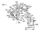
一実施形態においては、ロボット外科手術システムは、ベースと、ベースに動作可能に連結されたセットアップリンクとを有し、セットアップリンクはロボット外科手術システムの運動の遠隔中心を位置付ける。そのシステムは、セットアップリンクに動作可能に連結された近位リンクと、近位リンクに動作可能に連結された遠位リンクと、遠位リンクの遠位端に回転可能に連結された複数の器具マニピュレータとを更に有し、器具マニピュレータの各々は、フレームの遠位端から遠位方向に突き出た複数のアクチュエータ出力部を有する。 In one embodiment, the robotic surgical system has a base and a setup link operably coupled to the base, the setup link positioning a remote center of motion of the robotic surgical system. The system includes a proximal link operably connected to a setup link, a distal link operably connected to the proximal link, and a plurality of instruments rotatably connected to the distal end of the distal link And each of the instrument manipulators has a plurality of actuator outputs projecting distally from the distal end of the frame.
別の実施形態においては、ロボット外科手術システムは、上記の要素と、対応する器具マニピュレータの遠位端に動作可能に連結された複数の手術用器具とを有し、各々の器具は、対応する器具マニピュレータの対応するアクチュエータ出力部と係合される力伝達機構の近位面におけるアクチュエータ入力部を有する。 In another embodiment, a robotic surgical system includes the above elements and a plurality of surgical instruments operably coupled to a distal end of a corresponding instrument manipulator, each instrument correspondingly Actuator inputs on the proximal face of the force transmission mechanism engaged with corresponding actuator outputs of the instrument manipulator.
更に別の実施形態においては、ロボット外科手術システムのマニピュレータアームに手術用器具を連結する方法は、上記のロボット外科手術システムを提供する段階と、器具マニピュレータのアクチュエータ出力部及び手術用器具のアクチュエータ入力部を動作可能に連結する対応する器具マニピュレータの遠位端に手術用器具の近位端を搭載する段階とを有する。 In yet another embodiment, a method of coupling a surgical instrument to a manipulator arm of a robotic surgical system includes providing the robotic surgical system described above, and an actuator output of the instrument manipulator and an actuator input of the surgical instrument. Mounting the proximal end of the surgical instrument on the distal end of the corresponding instrument manipulator operably connecting the sections.
以下の詳細な1つ又はそれ以上の実施形態を検討することにより、当業者は、本発明の実施形態をより十分に理解することができ、それらの実施形態のさらなる有利点を認識することもできる。参照のために図を添付しており、それらの添付図について簡単に説明する。 By examining one or more of the following detailed embodiments, one of ordinary skill in the art can better understand the embodiments of the present invention and may recognize additional advantages of those embodiments. it can. The figures are attached for reference, and the attached figures are briefly described.
本発明の実施形態及びそれらの有利点については、以下の詳述説明により十分に理解できる。複数の図に示されている同じ要素には同じ参照番号を用いていることを理解する必要がある。図は必ずしもスケーリングして描かれてはいないことにも留意する必要がある。 Embodiments of the present invention and their advantages can be more fully understood from the following detailed description. It should be understood that the same reference numerals are used for the same elements shown in the figures. It should also be noted that the figures are not necessarily drawn to scale.
本明細書及び本発明の特徴及び実施形態を示す添付図は制限的であると捉えるべきではない。種々の機械的、構成的、構造的、電気的及び動作的変更が、本発明の主旨及び範囲から逸脱することなく行われることが可能である。一部の実施例においては、知られている回路、構造及び技術は、本発明を分かり難くしないように、詳細には記載及び図示されていない。2つ又はそれ以上の図における同じ参照番号は、同じ又は類似する要素を表している。 The accompanying drawings illustrating the specification and features and embodiments of the invention should not be construed as limiting. Various mechanical, structural, structural, electrical and operational changes can be made without departing from the spirit and scope of the invention. In some embodiments, well-known circuits, structures and techniques have not been described and illustrated in detail so as not to obscure the present invention. The same reference numbers in two or more figures represent the same or similar elements.
更に、本明細書の用語は、本発明を制限するように意図されていない。例えば、空間に関連する用語、例えば、“下に”、“下方に”、“より下に”、“より上に”、“上方に”、“近位に”、“遠位に”などは、図に示しているように他の要素又は特徴に対する1つの要素又は特徴の関連性を表すように用いられ得る。それらの空間に関連する用語は、図に示している位置及び方位に加えて、使用中の又は動作中の装置の異なる位置及び方位を含むように意図されている。例えば、図中の装置が入れ替えられる場合、他の要素又は特徴の“下方に”又は“下に”あるとして表される要素又は特徴は、その場合、他の要素又は特徴の“上方に”又は“上に”ある。従って、例示としての用語“下方に”は、“上方に”及び“下方に”の位置及び方位の両方を含み得る。装置はまた、方位付けられる(90°又は他の方位に回転される)ことが可能であり、本明細書で用いられている空間に関連する記述子は、それに応じて解釈される。同様に、種々の軸に沿った又は種々の軸の周囲の運動の記述は、種々の特定の装置の位置及び方位を含む。更に、単数表現は、そのコンテキストが別のように示していない限り、複数形も含むように意図されている。用語“から構成される”、“から成る”、“を有する”などの用語は、記載されている特徴、ステップ、動作、要素及び/又は構成要素を特定するが、1つ又はそれ以上の他の特徴、ステップ、動作、要素及び/又は構成要素の存在又は付加を排除しない。組み合わされて表現されている複数の構成要素は、電気的に又は機械的に直接結合されることが可能であり、又は、それらは、1つ又はそれ以上の中間構成要素を介して間接的に結合されることが可能である。 Furthermore, the terminology herein is not intended to limit the invention. For example, space related terms such as “down”, “down”, “below”, “above”, “up”, “proximal”, “distal” etc. Can be used to represent the relevance of one element or feature to another element or feature as shown. Terms associated with these spaces are intended to include different positions and orientations of the device in use or in operation in addition to the positions and orientations shown in the figures. For example, if a device in the figure is replaced, an element or feature represented as “below” or “below” another element or feature will then be “above” the other element or feature or "It is above. Thus, the exemplary term “down” may include both “up” and “down” positions and orientations. The device can also be oriented (rotated to 90 ° or other orientation), and the space related descriptors used herein are interpreted accordingly. Similarly, descriptions of movement along or around various axes include various specific device positions and orientations. Furthermore, the singular forms are intended to include the plural forms as well, unless the context indicates otherwise. The terms “consisting of”, “consisting of”, “having”, etc., identify the described feature, step, action, element, and / or component, but one or more other Does not exclude the presence or addition of features, steps, actions, elements and / or components. Multiple components expressed in combination can be directly coupled electrically or mechanically, or they can be indirectly indirectly through one or more intermediate components. Can be combined.
一実施例においては、用語“近位の”又は“近位に”は一般に、システム動作の運動学的連鎖に沿った運動の遠隔中心(又は外科手術部位)から遠く離れた、又はシステム動作の運動学的連鎖に沿ったマニピュレータアームベースに近接するオブジェクト又は要素を表現するように用いられる。同様に、用語“遠位の”又は“遠位に”は一般に、システム動作の運動学的連鎖に沿った運動の遠隔中心(又は外科手術部位)に近接する、又はシステム動作の運動学的連鎖に沿ったマニピュレータアームベースから遠く離れたオブジェクト又は要素を表現するように用いられる。 In one embodiment, the term “proximal” or “proximal” generally refers to a distance from a remote center of motion (or surgical site) along the kinematic chain of system motion, or of system motion. Used to represent an object or element proximate to the manipulator arm base along the kinematic chain. Similarly, the terms "distal" or "distally" generally refer to a remote center of motion (or surgical site) along the kinematic chain of system movement or the kinematic chain of system movement. Is used to represent an object or element that is far from the manipulator arm base along.
ロボットスレーブ装置を制御し、作業部位で作業を実行するように、マスター装置でオペレータの入力を用いることが知られている。そのようなシステムは、遠隔オペレーションシステム、遠隔操作システム又は遠隔ロボットシステムなど、種々呼称されている。一種類の遠隔操作システムは作業部位に存在する認知をオペレータに与え、そのようなシステムは、例えば、テレプレゼンスシステムと呼ばれている。米国カリフォルニア州サニーベール市のIntuitive Surgical,Inc.により商品化されているda Vinci(登録商標)外科手術システムは、テレプレゼンスを有する遠隔操作システムの例である。そのような外科手術システムのためのテレプレセンスの基本については、米国特許第6,574,355号明細書(2001年5月21日出願)に開示されていて、それは本明細書において参考により援用される。遠隔操作外科手術システム(テレプレゼンスの特徴の有無に拘わらず)は遠隔外科手術システムと称せられる。 It is known to use operator input at a master device to control a robot slave device and perform work at a work site. Such a system is variously referred to as a remote operation system, a remote operation system, or a remote robot system. One type of remote control system provides the operator with a cognition that exists at the work site, and such a system is called, for example, a telepresence system. Intuitive Surgical, Inc. of Sunnyvale, California, USA. The da Vinci® surgical system that is commercialized by is an example of a remote control system with telepresence. The basis of telepresence for such a surgical system is disclosed in US Pat. No. 6,574,355 (filed May 21, 2001), which is incorporated herein by reference. Is done. Teleoperated surgical systems (with or without telepresence features) are referred to as telesurgical systems.
種々の特徴及び例示としての実施形態について下記の図及び記載を繰り返すことを回避するように、多くの特徴は多くの側面及び実施形態に対して共通であることが理解される必要がある。記載又は図における側面の省略は、その側面が、その側面を組み込む実施形態から欠けていることを意味するものではない。そうではなく、そのような側面は、明確さのために及び冗漫な記載を回避するように、省略され得るものである。従って、1つの図示されている及び/又は記載されている実施形態を参照して記載している側面は、そうすることが実行不可能でない場合には、図示されている及び/又は記載されている他の実施形態と共に存在する並びにそれらに適用されることが可能である。 It should be understood that many features are common to many aspects and embodiments, so as to avoid repeating the following figures and description for various features and exemplary embodiments. Omission of a side surface in the description or figure does not mean that the side surface is missing from an embodiment incorporating that side surface. Rather, such aspects can be omitted for clarity and to avoid verbose descriptions. Accordingly, aspects described with reference to one illustrated and / or described embodiment are illustrated and / or described where it is not feasible to do so. As well as other embodiments that are present and applicable to them.
従って、複数の一般的な側面は下記の種々の記載に適用される。種々の外科手術用器具、ガイドチューブ及び器具アセンブリが本明細書において適用可能であり、それらについては、米国特許出願第11/762,165号明細書(2007年6月13日出願、米国特許出願公開第2008/0065105A1号明細書)にさらに記載されていて、それは本明細書において参考により援用される。外科手術用器具のみで、若しくはガイドチューブ、複数の器具及び/又は複数のガイドチューブのアセンブリが、本明細書で適用可能である。従って、種々の外科手術用器具が利用可能であり、各々の外科手術用器具は他の器具から独立して動作し、各々はエンドエフェクタを有する。一部の実施例においては、エンドエフェクタは、患者における単独のエントリポートを介して、直交空間で能動的に制御される少なくとも6自由度(すなわち、サージ、ヒーブ、スウェイ、ロール、ピッチ、ヨー)を有して、動作する。付加的なエンドエフェクタの1又はそれ以上の自由度が、例えば、把持器具又はせん断器具におけるエンドエフェクタの顎運動に適用されることが可能である。 Accordingly, several general aspects apply to the various descriptions below. A variety of surgical instruments, guide tubes and instrument assemblies are applicable herein and are described in US patent application Ser. No. 11 / 762,165 (filed Jun. 13, 2007, US patent application). Publication No. 2008 / 0065105A1), which is hereby incorporated by reference. Only surgical instruments, or guide tubes, multiple instruments and / or multiple guide tube assemblies are applicable herein. Accordingly, various surgical instruments are available, each surgical instrument operating independently of the other instrument, each having an end effector. In some embodiments, the end effector is at least 6 degrees of freedom that is actively controlled in orthogonal space via a single entry port in the patient (ie, surge, heave, sway, roll, pitch, yaw). To operate. One or more degrees of freedom of the additional end effector can be applied to the jaw movement of the end effector, for example in a gripping or shearing device.
例えば、少なくとも1つの外科手術エンドエフェクタが、複数の図に示されている又は表現されている。エンドエフェクタは、特定の外科手術機能(例えば、鉗子/把持器、持針器、はさみ、電気メスフック、ステープラ、クリップアプライヤ/レムーバなど)を実行する最小侵襲性外科手術器具又はアセンブリの部品である。多くのエンドエフェクタ自体は1自由度(例えば、開く及び閉じる把持器)を有する。エンドエフェクタは、例えば、“手首”型機構などの付加的な1又はそれ以上の自由度を提供する機構を有する外科手術器具本体に連結されることが可能である。そのような機構の例は、米国特許第6,371,952号明細書(1999年6月28日出願、Madhani等による)及び米国特許第6,817,974号明細書(2002年6月28日出願、Cooper等による)に示されていて、それらの両方は本明細書において参考により援用され、da Vinci(登録商標)Surgical Systemsのための8mm及び5mmの器具の両方で用いられる種々のIntuitive Surgical、Inc.のEndowrist(登録商標)機構として知られている。本明細書で記載している外科手術器具はエンドエフェクタを有するが、一部の特徴においては、エンドエフェクタは省略され得ることが理解される必要がある。例えば、器具本体シャフトのブラント遠位先端は、組織を収縮するように用いられることが可能である。他の例としては、吸引動作又は灌注動作が、本体シャフト又は手首機構の遠位先端に存在し得る。それらの特徴においては、エンドエフェクタを位置決め及び方向付けするという記載は、エンドエフェクタを有しない外科手術用器具の先端を位置決め及び方向付けすることを含むと、理解される必要がある。例えば、エンドエフェクタの先端のための基準フレームに対応する記載は、エンドエフェクタを有しない外科手術用器具の先端の基準フレームを有するように、読み取られる必要がある。 For example, at least one surgical end effector is shown or represented in multiple figures. An end effector is a part of a minimally invasive surgical instrument or assembly that performs a specific surgical function (eg, forceps / gripper, needle holder, scissors, electric scalpel hook, stapler, clip applier / remover, etc.) . Many end effectors themselves have one degree of freedom (eg, open and close grippers). The end effector can be coupled to a surgical instrument body having a mechanism that provides one or more additional degrees of freedom, such as, for example, a “wrist” type mechanism. Examples of such mechanisms are US Pat. No. 6,371,952 (filed Jun. 28, 1999, by Madhani et al.) And US Pat. No. 6,817,974 (June 28, 2002). Both of which are hereby incorporated by reference and used in both 8 mm and 5 mm instruments for da Vinci® Surgical Systems. Surgical, Inc. Known as the Endowrist® mechanism. Although the surgical instruments described herein have an end effector, it should be understood that in some features the end effector may be omitted. For example, the blunt distal tip of the instrument body shaft can be used to contract tissue. As another example, a suction or irrigation action may be present at the distal tip of the body shaft or wrist mechanism. In those features, the description of positioning and directing the end effector should be understood to include positioning and directing the tip of a surgical instrument that does not have an end effector. For example, a description corresponding to a reference frame for a tip of an end effector needs to be read to have a reference frame at the tip of a surgical instrument that does not have an end effector.
本明細書全体に亘って、エンドエフェクタが図示又は記載されている(その装置は“カメラ器具”とみなされ得る)ところであればどこでも、モノ(mono)又は立体撮像システム/画像取り込み部品/カメラ装置は、器具の遠位端に位置することが可能であり、又は、何れかのガイドチューブ又は他の器具アセンブリ要素の近位に又は遠位端に位置することが可能である。従って、本明細書で用いている用語“撮像システム”などは、記載されている特徴及び実施形態の範囲内で、画像取り込み部品、並びに関連する回路及びハードウェアと画像取り込み部品の組み合わせの両方を含むように広く解釈される必要がある。そのような内視鏡撮像システム(例えば、可視光、赤外線、超音波など)は、身体の外部に対して有線又は無線接続を介して取り込まれた画像データを中継する、遠位に位置付けられた画像検知チップ及び関連回路を有するシステムを有する。そのような内視鏡撮像システムは、身体の外側で取り込まれた画像を中継するシステムも有する(例えば、ロッドレンズ又は光ファイバを用いることにより)。一部の器具又は器具アセンブリにおいては、直視光学系(内視鏡画像が接眼部で直視される)を用いることが可能である。遠位に位置付けられた半導体立体撮像システムの例については、米国特許出願第11/614,661号明細書(“Stereoscopic Endscope”という名称で、Shafer等によるものであり、2006年12月21日に出願された)に開示されていて、それは本明細書において参考により援用される。知られている内視鏡撮像システムの構成要素、例えば、電気的照明接続及び光ファイバ照明接続は、明確化のために、省略する又は象徴的に表される。内視鏡撮像のための照明は典型的には、単独の照明ポートで図中に表される。そのような表現は例示であることが、理解される必要がある。照明ポートの大きさ、位置及び数は変更し得る。照明ポートは典型的には、濃い影を最小化するように、撮像開口の複数の側部に配列される、又は撮像開口を完全に取り囲む。 Throughout this specification, wherever an end effector is shown or described (the device may be considered a “camera instrument”), a mono or stereo imaging system / image capture component / camera device Can be located at the distal end of the instrument, or can be located proximal or at the distal end of any guide tube or other instrument assembly element. Accordingly, as used herein, the term “imaging system” and the like refers to both image capture components and associated circuitry and combinations of hardware and image capture components within the scope of the described features and embodiments. It needs to be interpreted widely to include. Such endoscopic imaging systems (eg, visible light, infrared, ultrasound, etc.) are located distally, relaying image data captured via a wired or wireless connection to the outside of the body A system having an image sensing chip and associated circuitry; Such endoscopic imaging systems also have systems that relay images captured outside the body (eg, by using rod lenses or optical fibers). In some instruments or instrument assemblies, it is possible to use a direct-view optical system (an endoscopic image is viewed directly at the eyepiece). An example of a distally located semiconductor stereo imaging system is described in US patent application Ser. No. 11 / 614,661 (named “Stereoscopic Endscope” by Shafer et al., On Dec. 21, 2006). Filed), which is incorporated herein by reference. Components of known endoscopic imaging systems, such as electrical lighting connections and fiber optic lighting connections, are omitted or symbolically represented for clarity. Illumination for endoscopic imaging is typically represented in the figure with a single illumination port. It should be understood that such a representation is exemplary. The size, location and number of lighting ports can vary. The illumination ports are typically arranged on the sides of the imaging aperture or completely enclose the imaging aperture to minimize dark shadows.
本明細書においては、外科手術用器具又はガイドチューブが患者の組織をこすらないように、カニューレが典型的に用いられる。カニューレは、切開及び自然開口の両方で用いられ得る。器具又はガイドチューブが挿入(長手方向)軸に対して頻繁に平行移動又は回転しない状況下では、カニューレを用いなくてもよい。送気を必要とする状況下では、カニューレは、器具又はガイドチューブを過ぎての過剰な送気ガスのリークを回避するように、シールを有することが可能である。手術部位で送気ガスを必要とする送気及び手順を支援するカニューレアセンブリの例については、米国特許出願第12/705,439号明細書(“Entry Guide for Multiple Instruments in a Single Port System”という名称で、2010年2月12日に出願された)に記載されていて、該出願の全開示は、全ての目的のために、本明細書において参考により援用される。送気を必要としない胸部の外科手術については、カニューレのシールは含まれなくてよく、しかも、器具又はガイドチューブの挿入軸の動きが最小である場合、カニューレ自体、含まれなくてよい。固いガイドチューブが、該ガイドチューブに対して挿入される器具のための一部の構成においては、カニューレとして機能し得る。カニューレ及びガイドチューブは、例えば、スチール又は押し出しプラスチックから成ることが可能である。スチールより安価なプラスチックは、一回使用のために適切である。 Herein, a cannula is typically used so that the surgical instrument or guide tube does not rub the patient's tissue. The cannula can be used for both incision and natural opening. In situations where the instrument or guide tube does not translate or rotate frequently with respect to the insertion (longitudinal) axis, the cannula may not be used. In situations where insufflation is required, the cannula can have a seal to avoid excessive insufflation gas leakage past the instrument or guide tube. For an example of a cannula assembly that supports insufflation and procedures that require insufflation gas at the surgical site, see US patent application Ser. No. 12 / 705,439 (“Entry Guide for Multiple Instruments in a Single Port System”). The entire disclosure of which application is hereby incorporated by reference for all purposes. For chest surgery that does not require insufflation, the cannula seal may not be included, and if the movement of the instrument or guide tube insertion axis is minimal, the cannula itself may not be included. A rigid guide tube may function as a cannula in some configurations for instruments inserted into the guide tube. The cannula and guide tube can be made of, for example, steel or extruded plastic. Plastics that are less expensive than steel are suitable for single use.
フレキシブルな外科手術器具及びガイドチューブの種々の例及びアセンブリについては、上記の米国特許出願第11/762,165号明細書に図示され且つ記載されている。この文献に記載されているそのようなフレキシビリティは、種々の方法で達成される。例えば、器具又はガイドチューブのセグメントは、連続的に曲がったフレキシブルな構造、例えば、螺旋巻き状コイル又は種々の除去部分(例えば、引目状切り口)を有するチューブに基づく構造であることが可能である。又は、そのフレキシブルな部分は、へびの様相を呈する連続的に曲げられた構造を提供する、一連の短く、枢動可能に接続されるセグメント(椎骨状のもの)から成ることが可能である。器具及びガイドチューブの構造については、米国特許出願公開第2004/0138700号明細書(Cooper等によるものであり、2003年12月2日に出願された)に記載されていて、それは本明細書において参考により援用される。明確化のために、その文献における図及び関連の記載は一般に、近位(伝達機構に近く、手術部位から遠い)及び遠位(伝達機構から遠く、手術部位に近い)と称せられる、器具及びガイドチューブの2つのセグメントのみを表している。器具及びガイドチューブは3つ又はそれ以上のセグメントに分割され得、各々のセグメントは固い、受動的にフレキシブルである、又は能動的にフレキシブルである。遠位のセグメント、近位のセグメント又は全体的な機構についての上記のフレキシビリティ及び曲げ性は、明確化のために省略されている中間セグメントにも適用可能である。例えば、近位セグメントと遠位セグメントとの間の中間セグメントは、単独曲線状に又は複合曲線状に曲がることが可能である。フレキシブルなセグメントは種々の長さであることが可能である。より小さい外側直径を有するセグメントは、より小さい最小の曲率半径を有することが可能である一方、より大きい外側直径を有するセグメントより曲げ性が大きい。ケーブルが制御されるシステムについては、許容できない高いケーブル摩擦又はケーブル結束が、最小の曲率半径及び曲げるときの全屈曲角度を制約する。ガイドチューブ(又は、何れかのジョイント)の最小の屈曲角度は、そのガイドチューブがねじれない、又は内側の外科手術用器具の機構のスムーズな動きを阻害するようなものである。フレキシブルな構成要素は、例えば、最大で、長さが略4フィートであり得、直径が略0.6インチであり得る。特定の機構のための、他の長さ及び直径(例えば、より短い、より小さい)並びにフレキシビリティの度合いは、その機構が設計された対象の生体組織により決定され得る。 一部の実施例においては、器具又はガイドチューブの遠位セグメントのみがフレキシブルであり、近位セグメントは固い。他の実施例においては、患者の内部にある器具又はガイドチューブの全体的なセグメントがフレキシブルである。更に他の例においては、最遠位セグメントは固いことが可能であり、1つ又はそれ以上の他の近位セグメントはフレキシブルであることが可能である。それらのフレキシブルなセグメントは受動的に制御可能である、又は能動的に制御可能(操縦可能)である。そのような能動的制御は、例えば、複数の対向するケーブルの複数のセット(例えば、1つのセットは“ピッチ”を制御し、直交するセットは“ヨー”を制御し、3本のケーブルが類似する動作をするように用いられる)を用いて、行われ得る。他の制御要素、例えば、小さい電動アクチュエータ又は磁気アクチュエータ、形状記憶合金、電気活性ポリマー(人工筋肉)、空気圧又は油圧ベローズ又はピストンなどが用いられることが可能である。器具又はガイドチューブのセグメントが完全に又は一部が他のガイドチューブの内側にある実施例においては、受動的フレキシビリティ及び能動的フレキシビリティの種々の組み合わせが存在し得る。例えば、受動的フレキシブルガイドチューブの内側の能動的フレキシブル器具は、取り囲んでいるガイドチューブを撓めるのに十分な横方向の力を作用させ得る。同様に、能動的フレキシブルガイドチューブは、その内側の受動的フレキシブル器具を撓め得る。ガイドチューブ及び器具の能動的フレキシブルセグメントは協調して作用し得る。フレキシブルな器具及びガイドチューブ並びに固い器具及びガイドチューブの両方については、長手方向中心軸から離れて位置付けられた制御ケーブルは、種々の設計におけるコンプライアンス考慮に応じて、長手方向中心軸に近接して位置付けられたケーブルに対して機械的アドバンテージを与え得る。 Various examples and assemblies of flexible surgical instruments and guide tubes are shown and described in the above-mentioned US patent application Ser. No. 11 / 762,165. Such flexibility as described in this document can be achieved in various ways. For example, the segment of the instrument or guide tube can be a continuously bent flexible structure, such as a tube-based structure with a spiral wound coil or various removal portions (eg, cut-out cuts). is there. Alternatively, the flexible portion can consist of a series of short, pivotally connected segments (vertebral) that provide a continuously bent structure that exhibits a snake-like appearance. The structure of the instrument and guide tube is described in U.S. Patent Application Publication No. 2004/0138700 (cooper et al., Filed Dec. 2, 2003), which is hereby incorporated by reference. Incorporated by reference. For clarity, the figures and related descriptions in that document are generally referred to as proximal (close to the transmission mechanism and far from the surgical site) and distal (far from the transmission mechanism and close to the surgical site) Only two segments of the guide tube are shown. The instrument and guide tube can be divided into three or more segments, each segment being rigid, passively flexible, or actively flexible. The above flexibility and bendability for the distal segment, the proximal segment or the overall mechanism is also applicable to the intermediate segment which has been omitted for clarity. For example, the intermediate segment between the proximal and distal segments can be bent in a single curve or in a compound curve. The flexible segment can be of various lengths. A segment with a smaller outer diameter can have a smaller minimum radius of curvature while being more bendable than a segment with a larger outer diameter. For systems where the cable is controlled, unacceptably high cable friction or cable ties limit the minimum radius of curvature and the total bend angle when bending. The minimum bending angle of the guide tube (or any joint) is such that the guide tube does not twist or hinders smooth movement of the inner surgical instrument mechanism. The flexible component can be, for example, up to approximately 4 feet in length and approximately 0.6 inches in diameter. Other lengths and diameters (eg, shorter, smaller) and degree of flexibility for a particular mechanism can be determined by the anatomy of the subject for which the mechanism is designed. In some embodiments, only the distal segment of the instrument or guide tube is flexible and the proximal segment is stiff. In other embodiments, the entire segment of the instrument or guide tube inside the patient is flexible. In still other examples, the most distal segment can be stiff and one or more other proximal segments can be flexible. These flexible segments are passively controllable or actively controllable (steerable). Such active control may be, for example, multiple sets of opposing cables (eg, one set controls “pitch”, an orthogonal set controls “yaw”, and three cables are similar Can be used to do the same). Other control elements such as small electric or magnetic actuators, shape memory alloys, electroactive polymers (artificial muscles), pneumatic or hydraulic bellows or pistons can be used. In embodiments where the instrument or guide tube segments are wholly or partially inside other guide tubes, various combinations of passive and active flexibility may exist. For example, an active flexible device inside a passive flexible guide tube can exert a sufficient lateral force to deflect the surrounding guide tube. Similarly, the active flexible guide tube can deflect the passive flexible instrument inside it. The active flexible segment of the guide tube and instrument can act in concert. For both flexible instruments and guide tubes and rigid instruments and guide tubes, control cables positioned away from the longitudinal central axis are positioned close to the longitudinal central axis depending on compliance considerations in various designs. A mechanical advantage can be given to the cable provided.
フレキシブルなセグメントのコンプライアンス(剛性)は、略完全な弛緩性(わずかな内部摩擦は存在する)から実質的な硬性まで変わり得る。一部の特徴においては、そのコンプライアンスは制御可能である。例えば、器具又はガイドチューブのフレキシブルなセグメントの一部又は全部は実質的に(即ち、効果的にではあるが究極的にではなく)固い(セグメントは“剛体化可能”又は“ロック可能”である)。ロック可能なセグメントは、直線形、単純曲線状又は複合曲線状にロックされることが可能である。ロッキングは、隣接する椎骨形状構造が動かなくなる摩擦をもたらすのに十分である器具又はガイドチューブに沿って長手方向に移動する1つ又はそれ以上のケーブルに張力を加えることにより、達成され得る。1つのケーブル又は複数のケーブルが、各々の椎骨形状構造における大きい、中央の穴を通って移動することが可能であり、又は、椎骨形状構造の外周近傍の小さい穴を通って移動することが可能である。それに代えて、1つ又はそれ以上の制御ケーブルを動かす1つ又はそれ以上のモータの駆動要素が、適切な位置にケーブルを保持し、それにより器具又はガイドチューブが移動しないようにし、故に、適切な位置に椎骨状構造をロックするように、適切な位置に穏やかにロックされることが可能である(例えば、サーボ制御により)。適切な位置へのモータ駆動要素の保持は、適切な位置に他の移動可能な器具及びガイドチューブの構成要素も効果的に保持するように、なされ得る。サーボ制御下での剛性は、効果的であるが、ジョイントに直接位置付けられるブレーキ、例えば、適切な位置に能動的セットアップジョイントを保持するように用いられるブレーキにより得られる剛性より一般に小さいことを、理解する必要がある。ケーブルの剛性は一般に、サーボシステムの又はブレーキが掛けられたジョイントの剛性より小さいために、支配する。 The compliance (stiffness) of the flexible segment can vary from nearly perfect relaxivity (there is little internal friction) to substantial stiffness. In some features, the compliance is controllable. For example, some or all of the flexible segments of the instrument or guide tube are substantially rigid (ie, effective but not ultimately) (the segment is “rigidizable” or “lockable”) ). Lockable segments can be locked in a straight, simple or compound curve. Locking can be achieved by applying tension to one or more cables that move longitudinally along the instrument or guide tube that is sufficient to cause friction that causes the adjacent vertebral shape structure to move. One cable or multiple cables can move through a large, central hole in each vertebral shape structure, or can move through a small hole near the periphery of the vertebral shape structure It is. Alternatively, one or more motor drive elements that move one or more control cables hold the cables in the proper position, thereby preventing movement of the instrument or guide tube, and therefore appropriate It can be gently locked in place (eg, by servo control) to lock the vertebral structure in place. Holding the motor drive element in the proper position can be done to effectively hold other movable instruments and guide tube components in the proper position. Understand that the stiffness under servo control is effective but generally less than that obtained with brakes that are positioned directly on the joint, for example, brakes used to hold the active setup joint in place There is a need to. Cable stiffness generally dominates because it is less than the stiffness of the servo system or braked joint.
一部の状況下では、フレキシブルなセグメントのコンプライアンスは、弛緩性状態と硬性状態との間で連続的に変えられ得る。例えば、ロッキングケーブルの張力は、剛性を高くするように、しかし、硬性状態でフレキシブルなセグメントをロッキングすることなく、大きくされることが可能である。そのような中間的なコンプライアンスは、手術部位からの反応力によりもたらされる動きのために生じ得る組織の外傷を低減しつつ、遠隔手術動作を可能にする。フレキシブルなセグメントに組み込まれる適切な曲げセンサは、遠隔手術システムが器具及び/又はガイドチューブの位置を、それが曲がるときに、決定することを可能にする。米国特許出願公開第2006/0013523号明細書(Childers等によるものであり、2005年7月13日に出願された)には、光ファイバ位置形状検知装置及び方法について開示されていて、それは本明細書において参考により援用される。米国特許出願公開第11/491,384号明細書(Larkin等によるものであり、2006年7月20日に出願された)には、そのようなセグメント及びフレキシブルな装置の制御で用いられる光ファイバ曲げセンサ(例えば、ファイバブラッグ格子)について開示されていて、それは本明細書において参考により援用される。 Under some circumstances, compliance of the flexible segment can be continuously changed between a relaxed state and a rigid state. For example, the tension of the locking cable can be increased to increase rigidity, but without locking the flexible segment in the rigid state. Such intermediate compliance enables telesurgical operation while reducing tissue trauma that can occur due to movement caused by reactive forces from the surgical site. A suitable bend sensor incorporated into the flexible segment allows the telesurgical system to determine the position of the instrument and / or guide tube as it bends. US 2006/0013523 (by Childers et al., Filed Jul. 13, 2005) discloses an optical fiber position shape sensing apparatus and method, which is described herein. Incorporated herein by reference. US patent application Ser. No. 11 / 491,384 (by Larkin et al., Filed on Jul. 20, 2006) describes optical fibers used in the control of such segments and flexible devices. A bending sensor (eg, a fiber Bragg grating) is disclosed and is incorporated herein by reference.
本明細書で記載している最小侵襲性器具アセンブリ、器具、エンドエフェクタ及びマニピュレータアーム構成の特徴を制御する外科医の入力は一般に、直感的なカメラ基準の制御インタフェースを用いて行われる。例えば、da Vinci(登録商標)Surgical Systemは、そのような制御インタフェースを有する外科医用コンソールを有し、その制御インタフェースは、本明細書で記載している特徴を制御するように改善されることが可能である。外科医は、例えば、スレーブ器具アセンブリ及び器具を制御する6自由度を有する1つ又はそれ以上のマスターマニュアル入力機構を操作する。それらの入力機構は、1つ又はそれ以上のエンドエフェクタの自由度(例えば、把持顎部を閉じる)を制御する指操作把持器を有する。直感的な制御は、外科医の入力機構及び画像出力ディスプレイの位置との、エンドエフェクタ及び内視鏡撮像システムの相対的位置を方位付けることにより、与えられる。この方位付けは、実質的に実際にその場にいて手術作業部位を見ているかのように、入力機構及びエンドエフェクタ制御を外科医が操作することを可能にする。このような遠隔操作において実際にその場にいるかのようなことは、外科医が、手術部位を直接見て作業しているオペレータの透視のように現れる透視からの画像を見ることを意味する。米国特許第6,671,581号明細書(Niemeyer等によるものであり、2002年6月5日に出願された)には、最小侵襲性手術装置におけるカメラ基準の制御に関する更なる情報が開示されていて、それは本明細書において参考により援用される。 The surgeon's input to control the features of the minimally invasive instrument assembly, instrument, end effector, and manipulator arm configurations described herein is typically done using an intuitive camera-based control interface. For example, da Vinci® Surgical System has a surgeon console with such a control interface, which control interface may be improved to control the features described herein. Is possible. The surgeon operates, for example, a slave instrument assembly and one or more master manual input mechanisms with six degrees of freedom to control the instrument. These input mechanisms have a finger operated gripper that controls the degree of freedom (eg, closing the gripping jaws) of one or more end effectors. Intuitive control is provided by orienting the relative position of the end effector and endoscopic imaging system with respect to the surgeon's input mechanism and the position of the image output display. This orientation allows the surgeon to manipulate the input mechanism and end effector control substantially as if actually in place and looking at the surgical work site. Such a remote operation as if actually in place means that the surgeon sees an image from a perspective that appears as if the operator is looking directly at the surgical site. US Pat. No. 6,671,581 (by Niemeyer et al. And filed on June 5, 2002) discloses further information regarding camera reference control in minimally invasive surgical devices. Which is hereby incorporated by reference.
シングルポート外科手術システム
ここで図1A及び1Bを参照するに、本明細書で記載されている最小侵襲性外科手術用器具、器具アセンブリ、操作システム及び制御システムの特徴を用いるロボット支援(遠隔操作)最小侵襲性外科手術システムの特徴の例示である側面図及び正面図が示されている。主な3つの構成要素は、内視鏡撮像システム102、外科医用コンソール104(マスター)及び患者側サポートシステム100(スレーブ)であり、それらのすべてが、図示されている有線接続(電気的又は光学的)又は無線接続106により相互接続されている。1つ又はそれ以上の電子データプロセッサは、システムの機能を備えるようにそれら主要な構成要素において様々に設置されることが可能である。その例については、上記の米国特許出願第11/762,165号明細書に開示されている。破線で示されている殺菌ドレープ1000は、外科手術手順中に殺菌フィールドを維持する一方、器具とその器具に関連するマニピュレータとの間を正確なインタフェースで連結して効率的で簡単な器具交換を提供するように、患者側サポートシステム100の少なくとも一部を有利に覆う。Single Port Surgical System Referring now to FIGS. 1A and 1B, robotic assistance (remote control) using features of the minimally invasive surgical instrument, instrument assembly, operating system and control system described herein. Illustrated are side and front views illustrating features of a minimally invasive surgical system. The three main components are the
撮像システム102は、例えば、取り込まれた手術部位の内視鏡撮像データ及び/又は患者の外部の他の撮像システムからの透視又はリアルタイム画像データに関して画像処理機能を実行する。撮像システム102は、処理画像データ(例えば、手術部位の画像並びに関連制御情報及び患者情報)を外科医に対して外科医用コンソール104において出力する。一部の特徴においては、処理画像データは、他の操作室の担当者に可視的なオプションの外部モニタに、又はその操作室から遠く離れた1つ又はそれ以上の場所(例えば、他の場所の外科医が映像をモニタすることが可能であり、ライブ映像がトレーニングなどのために使用可能である)に、出力される。 The
外科医用コンソール104は、例えば、外科医が、本明細書で記載している、外科手術器具、ガイドチューブ及び撮像システム(スレーブ)装置を操作することを可能にする、複数自由度を有する機械入力(マスター)装置を有する。それらの入力装置は、一部の特徴において、器具及び器具アセンブリ構成要素から外科医への触覚フィードバックを提供することが可能である。コンソール104は、表示スクリーンの後/下での外科医の手作業に対応する距離で、ディスプレイ上に画像が一般にフォーカシングされるように、位置付けられた立体映像出力ディスプレイも有する。それらの特徴については、米国特許第6,671,581号明細書に詳しく記載されていて、それは本明細書において参考により援用される。 The
挿入中の制御は、例えば、マスターの一方又は両方を用いて画像を仮想的に移動させる外科医により行われ得、その外科医は、左右に画像を動かし、彼女自身の方にその画像を引き寄せるようにマスターを使用し、従って、出力表示における固定された中心点の方に操縦し、患者の内部に進むように、撮像システム及び関連器具アセンブリに指令するように、それらのマスターを用いる。一特徴においては、カメラコンソールは、マスターハンドルが移動されるのと同じ方向に画像が移動するようにマスターを画像に対して固定する印象を与えるように、設計されている。この設計は、外科医がカメラコンソールから抜け出るときに器具を制御する正確な位置にマスターがあるようにし、従って、器具制御を開始又は再開する前の位置にクラッチ操作する(外す)、動かす及びクラッチ解除する(関与させる)必要性を回避する。一部の特徴においては、マスターの位置は、大きいマスター作業空間を用いることを避けるように、挿入速度に比例するようにされ得る。それに代えて、外科医は、挿入のためにラチェット動作を用いるように、マスターをクラッチ操作する及びクラッチ解除することが可能である。一部の特徴においては、挿入は手動で制御され(例えば、手動式ホイールにより)、更には、自動挿入(例えば、サーボモータ駆動ローラー)が、外科手術用器具アセンブリの遠位端が手術部位の近傍にあるときに行われる。挿入軌跡のために利用可能な患者の解剖学的構造及び空間の手術前画像データ又はリアルタイム画像データ(例えば、MRIデータ、X線データ)が、挿入を支援するように用いられることが可能である。 Control during insertion can be performed, for example, by a surgeon that virtually moves the image using one or both of the masters, so that the surgeon moves the image from side to side and pulls the image towards herself. Use the masters, and therefore use them to command the imaging system and associated instrument assembly to steer toward a fixed center point in the output display and advance into the patient. In one aspect, the camera console is designed to give the impression of fixing the master relative to the image so that the image moves in the same direction as the master handle is moved. This design ensures that the master is in the exact position to control the instrument as the surgeon exits the camera console, thus clutching (disengaging), moving and releasing the clutch to the position before starting or resuming instrument control. Avoid the need to do (involve). In some features, the position of the master can be made proportional to the insertion speed so as to avoid using a large master workspace. Alternatively, the surgeon can clutch and disengage the master to use a ratcheting action for insertion. In some features, the insertion is manually controlled (eg, by a manual wheel), and even automatic insertion (eg, a servo motor driven roller), where the distal end of the surgical instrument assembly is located at the surgical site. Performed when in the vicinity. Patient anatomy and spatial pre-operative image data or real-time image data (eg, MRI data, x-ray data) available for the insertion trajectory can be used to assist with the insertion. .
患者側サポートシステム100は、床置き式ベース108、又は破線で示されている天井付けベース110を有する。そのベースは移動可能である又は固定される(例えば、床、天井、壁又は操作テーブル等の他の装置に)ことが可能である。 The patient-
ベース108は、受動的非制御“セットアップ”部分及び能動的制御“マニピュレータ”部分を有するアームアセンブリを支持する。一実施例においては、そのセットアップ部分は、2つの受動的回転 “セットアップ”ジョイント116及び120を有し、それらは、ジョイントのブレーキが開放されるときに、連結セットアップリンク118及び122の手動による位置決めを可能にする。アームアセンブリとリンク114に連結されたベースとの間の受動的角柱状セットアップジョイント(図示せず)は、大きい鉛直方向の調整112を可能にするように用いられ得る。それに代えて、それらのセットアップジョイントの一部は能動的に制御されることが可能であり、多かれ少なかれセットアップジョイントは様々な構成で用いられることが可能である。セットアップジョイント及びリンクは、直交(x,y,z)空間における種々の位置及び方位でアームのロボットマニピュレータ部分を人間が位置付けることを可能にする。運動の遠隔中心は、ヨー軸、ピッチ軸及びロール軸が交差する位置(即ち、運動学的連鎖が効果的に変化しないで保たれる一方、ジョイントはその運動の範囲内で動く位置)である。下で詳細に説明するように、それらの能動的に制御されるジョイントの一部は、個別の外科手術用器具の自由度の制御に関連付けられるロボットマニピュレータであり、それらの能動的に制御されるジョイントの他は、それらのロボットマニピュレータの単独のアセンブリの自由度の制御に関連付けられる。能動的ジョイント及びリンクは、モータ及び他のアクチュエータにより移動可能であり、外科医用コンソール104でマスターアームの運動に関連する運動制御信号を受ける。 The
図1A及び1Bに示しているように、マニピュレータアセンブリヨージョイント124は、セットアップリンク122の遠位端と第1マニピュレータリンク126の近位端との間に連結される。ヨージョイント124は、マニピュレータアセンブリヨー軸123の周囲の“ヨー”として任意に規定され得る動きにおいて、リンク126がリンク122に対して動くことを可能にする。図示しているように、ヨージョイント124の回転軸は運動の遠隔中心146と位置合わせされ、その遠隔中心は一般に、器具(図示せず)が患者の体内に入る位置(例えば、腹部の外科手術についてのへそ)である。一実施形態においては、セットアップリンク122は、水平面又はxy平面に沿って回転可能であり、ヨージョイント124は、第1マニピュレータリンク126がヨー軸123に関して回転することが可能であり、故に、セットアップリンク122、ヨージョイント124及び第1マニピュレータリンク126は、ヨージョイント124から運動の遠隔中心146までの鉛直方向の破線で示されているように、ロボットアームアセンブリについて常に鉛直方向にあるヨー軸123を与える。 As shown in FIGS. 1A and 1B, the manipulator assembly yaw joint 124 is coupled between the distal end of the
能動的に制御される回転ジョイント128、132及び136のそれぞれにより、第1マニピュレータリンク126の遠位端は、第2マニピュレータ130の近位端に連結され、第2マニピュレータリンク130の遠位端は、第3マニピュレータ134の近位端に連結され、第3マニピュレータリンク134の遠位端は、第4マニピュレータ138の近位端に連結されている。一実施形態においては、リンク130、134及び138は、連結された運動機構としての役割を果たすように、一緒に連結されている。連結された運動機構は知られている(例えば、そのような機構は、入力リンク運動及び出力リンク運動が互いに対して平行に保たれるときの平行運動連鎖として知られている)。例えば、回転ジョイント128が能動的に回転される場合、ジョイント132及び136はまた、リンク138がリンク130に対して一定の関係を有して動くように、回転する。従って、ジョイント128、132及び136の回転軸は平行であることが理解できる。それらの軸が、ジョイント124の回転軸に対して垂直であるとき、リンク130、134及び138は、マニピュレータアセンブリピッチ軸139の周囲で“ピッチ”として任意に規定され得る運動において、リンク126に関して動く。リンク130、134及び138は、一実施形態においては、単独のアセンブリとして動くため、第1マニピュレータリンク126は能動的近位マニピュレータリンクとみなされ得、第2乃至第4マニピュレータリンク130、134及び138は、集合的に能動的遠位マニピュレータリンクとみなされ得る。 マニピュレータアセンブリプラットフォーム140は、第4マニピュレータリンク138の遠位端に連結している。マニピュレータプラットフォーム140は、下で詳細に説明する、2つ又はそれ以上の外科手術用器具マニピュレータを有するマニピュレータアセンブリ142を支持する回転可能ベースプレートを有する。その回転可能ベースプレートは、マニピュレータアセンブリロール軸141の周囲の“ロール”として任意に規定され得る運動において、プラットフォーム140に関する単独のユニットとして、マニピュレータアセンブリ142が回転することを可能にする。 Each of the actively controlled
最小侵襲性外科手術のためには、器具は、不必要な組織の損傷を回避するように、切開か自然開口かのどちらかで、その器具が患者の身体に入る位置に関連して、実質的に固定されたまま維持される必要がある。従って、器具シャフトのヨー運動及びピッチ運動は、空間において相対的に固定されたままであるマニピュレータアセンブリロール軸又は器具挿入軸に関して単独の位置に中心合わせされる必要がある。この位置は、運動の遠隔中心と称せられる。すべての器具(カメラ器具を含む)が単独の小さい切開(例えば、へそ)又は自然開口を介して入る必要があるシングルポート最小侵襲性外科手術については、すべての器具が、そのような一般に静止した運動の遠隔中心に関して動く必要がある。従って、マニピュレータアセンブリ142についての運動の遠隔中心は、マニピュレータアセンブリヨー軸123及びマニピュレータアセンブリピッチ軸139の交点により規定される。リンク130、134及び138並びにジョイント128、132及び136の構成は、マニピュレータアセンブリが患者に関して自由に動くことを可能にするのに十分な距離を有して運動の遠隔中心146がマニピュレータアセンブリ142の遠位に位置付けられるようなものである。マニピュレータアセンブリロール軸141はまた、運動の遠隔中心146と交差することが理解できる。 For minimally invasive surgery, the instrument is either substantially incision or natural opening relative to the location where the instrument enters the patient's body, so as to avoid unnecessary tissue damage. Must be kept fixed. Thus, the yaw and pitch movements of the instrument shaft need to be centered in a single position with respect to the manipulator assembly roll axis or instrument insertion axis that remains relatively fixed in space. This position is referred to as the remote center of movement. For single-port minimally invasive surgery where all instruments (including camera instruments) need to enter through a single small incision (eg, navel) or natural opening, all instruments are such stationary Need to move with respect to the remote center of movement. Accordingly, the remote center of motion for the
下で詳細に説明するように、外科手術用器具は、マニピュレータアセンブリ142の各々の外科手術用器具マニピュレータにより備えられ且つ動作される。それらの器具は、種々の器具が特定の器具マニピュレータに相互交換可能に備えられることが可能であるように、取り外し可能に備えられる。一特徴においては、1つ又はそれ以上の器具マニピュレータは、特定種類の器具、例えば、カメラ器具を支持する及び動作させることが可能である。器具のシャフトは、器具マニピュレータから遠位方向に延在している。シャフトは、エントリポートに位置付けられた共通カニューレを介して患者の体内に延在している(例えば、体壁を通って又は自然開口において)。一特徴においては、エントリガイドはカニューレにおいて位置付けられ、各々の器具シャフトは、器具シャフトのための付加的な支持を与えるように、エントリガイド内のチャネルの中を通って延びている。カニューレは、一実施形態においては、第4マニピュレータリンク138の近位端に連結されるカニューレマウント150に取り外し可能に連結される。一実施形態においては、カニューレマウント150は、運動の遠隔中心146がカニューレに沿って位置付けられるように、正確な位置にカニューレを保持する動作位置とリンク138に隣接する収容位置との間をそのマウントが移動することを可能にする回転ジョイントにより、リンク138に連結される。動作中、カニューレマウントは、一特徴に従って、リンク138に対して適切な位置に固定される。器具は、カニューレマウント150の遠位端に搭載されたカニューレアセンブリ及びエントリガイドを介してスライドすることが可能であり、その実施例については、下で詳述する。種々の受動的セットアップジョイント/リンク及び能動的ジョイント/リンクは、患者が移動可能なテーブル上の種々の位置に位置付けられるときに、器具マニピュレータの位置決めにより、大きい移動範囲を伴って器具及び撮像システムを移動させるようにする。一部の実施形態においては、カニューレマウントは、近位リンク又は第1マニピュレータリンク126に連結されることが可能である。 As described in detail below, a surgical instrument is provided and operated by each surgical instrument manipulator of the
マニピュレータアームにおける特定のセットアップジョイント及びリンク並びに能動的ジョイント及びリンクは、ロボットの大きさ及び形状を減少させるように除かれることが可能であり、又は、ジョイント及びリンクは、自由度を増すように、追加されることが可能である。マニピュレータアームは、外科手術のために必要な姿勢の範囲を得るように、リンク、受動的ジョイント及能動的ジョイント(冗長自由度が備えられることが可能である)の種々の組み合わせを有することが可能であることを理解する必要がある。更に、種々の外科手術用器具のみ、又は、ガイドチューブ、複数の器具及び/又は複数のガイドチューブ、並びに器具マニピュレータに結合された器具(例えば、アクチュエータアセンブリ)を有する器具アセンブリが、種々の構成(例えば、器具伝達手段又は器具マニピュレータの近位面又は遠位面上の)を介して、本発明の特徴に適用可能である。 Certain setup joints and links and active joints and links in the manipulator arm can be eliminated to reduce the size and shape of the robot, or the joints and links can be increased in freedom. It can be added. The manipulator arm can have various combinations of links, passive joints and active joints (which can be provided with redundant degrees of freedom) to obtain the range of postures required for surgery It is necessary to understand that. Additionally, various surgical instruments alone or instrument assemblies having a guide tube, multiple instruments and / or multiple guide tubes, and an instrument (eg, an actuator assembly) coupled to an instrument manipulator may have various configurations ( For example, it can be applied to features of the present invention via instrument delivery means or on the proximal or distal face of an instrument manipulator.
図2A乃至2Cは、遠隔操作外科手術(遠隔手術)システムにおける患者側支持カート200の斜視図、側面図及び平面図のそれぞれを示している。図示しているカート200は、図1A及び1Bに関連して上で説明している一般的な構成の例示としての実施形態である。外科医用コンソール及び映像システムは示されていないが、図1A及び1Bに関連して上で説明しているように適用可能であり、遠隔ロボット外科手術システムアーキテクチャ(例えば、da Vinci(登録商標)Surgical Systemアーキテクチャ)として知られている。この実施形態においては、カート200は床置き式ベース208を有する。そのベースは、移動可能である又は(例えば、床、天井、壁又は他の十分に固い構造に)固定されることが可能である。ベース208は支持柱210を支持し、アームアセンブリ201は支持柱210に連結されている。アームアセンブリは、2つの受動的回転セットアップジョイント216及び220を有し、それらは、それらのブレーキが開放されるときに、連結されているセットアップリンク218及び222の手動による位置決めを可能にする。図示している実施形態においては、セットアップリンク218及び222は水平面内を(床に対して平行に)動く。アームアセンブリは、支持柱210と鉛直方向のセットアップリンク214との間の受動的スライディングセットアップジョイント215において支持柱210に連結されている。ジョイント215は、マニピュレータアームが鉛直方向に調整される(床に対して垂直である)ようにする。従って、受動的セットアップジョイント及びリンクは、患者に対する運動の遠隔中心246を適切に位置付けるように用いられ得る。一旦、運動の遠隔中心246が適切に位置付けられると、ジョイント215、216及び220の各々におけるブレーキが、アームの設定部分を動かさないように定められる。 2A to 2C show a perspective view, a side view, and a plan view, respectively, of a patient-
更に、アームアセンブリは、マニピュレータアーム構成及び運動、器具操作並びに器具挿入のための能動的ジョイント及びリンクを有する。第1マニピュレータリンク226の近位端は、能動的制御回転マニピュレータアセンブリヨージョイント224を介してセットアップリンク222の遠位端に連結される。図示しているように、ヨージョイント224の回転マニピュレータアセンブリヨー軸223は、ヨージョイント224から運動の遠隔中心246まで、鉛直方向の破線で示しているように、運動の遠隔中心246と位置合わせされる。 In addition, the arm assembly has active joints and links for manipulator arm configuration and movement, instrument operation and instrument insertion. The proximal end of the
能動的制御回転ジョイント228、232及び236のそれぞれにより、第1マニピュレータリンク226の遠位端は第2マニピュレータリンク230の近位端に連結され、第2マニピュレータリンク230の遠位端は第3マニピュレータリンク234の近位端に連結され、第3マニピュレータリンク234の遠位端は第4マニピュレータリンク238の近位端に連結されている。上記のように、リンク230、234及び238は連結された運動機構として機能し、故に、第4マニピュレータリンク238は、第2マニピュレータリンク230が作動されるときに、リンク230と協調して自動的に動く。図示している実施形態においては、米国特許第7,594,912号明細書(2004年9月30日に出願された)に開示されている機構と類似する機構が使用するために改善されたものである(米国特許出願第11/611,849号明細書(2006年12月15日出願、米国特許出願公開第2007/0089557A1号明細書)も参照されたい)。従って、第1マニピュレータリンク226は能動的近位リンクとみなされ得、第2乃至第4マニピュレータリンク230、234及び238は集合的に能動的遠位リンクとみなされ得る。一実施形態においては、第1リンク226は、下で更に説明しているように、ジョイント228について遠位リンクの運動からの力と釣り合うように、圧縮バネ釣り合い機構を有することが可能である。 Each of the active control
マニピュレータアセンブリプラットフォーム240は第4リンク238の遠位端に連結されている。プラットフォーム240は、器具マニピュレータアセンブリ242が搭載されたベースプレート240aを有する。図2Aに示しているように、プラットフォーム240は“ハロー”リングを有し、そのハローリングの内側では、ディスク形状のベースプレート240aが回転する。ハロー及びディスク以外の形状が、他の実施形態で用いられ得る。ベースプレート240aの回転中心は、マニピュレータプラットフォーム240の中心及び運動の遠隔中心246を通って延びている破線で示されているように、マニピュレータアセンブリロール軸241と一致している。器具260が、一実施形態においては、器具マニピュレータの遠位面におけるマニピュレータアセンブリ242の器具マニピュレータに対して搭載される。
図2A及び2Bに示しているように、器具マニピュレータアセンブリ242は4つの器具マニピュレータ242aを有する。各々の器具マニピュレータは関連器具を支持し、且つその関連器具を動作させる。図示している実施形態においては、1つの器具マニピュレータ242aがカメラ器具を動作させ、3つの器具マニピュレータ242aが、手術部位での手術及び/又は診断作業を実行する種々の他の交換可能な外科手術用器具を動作させる。より多い又はより少ない器具マニピュレータが用いられ得る。一部の操作構成においては、1つ又はそれ以上のマニピュレータは、外科手術手順の一部又は全部において、関連手術用器具を有しないことが可能である。器具マニピュレータについては、下でより詳細に説明する。 As shown in FIGS. 2A and 2B, the
上で説明しているように、外科手術用器具260がそれぞれの器具マニピュレータ242aにより備えられていて、その外科手術用器具は器具マニピュレータにより作動される。本発明の特徴に従って、各々の器具は、その器具の近位端のみにおいて関連マニピュレータに対して備えられる。図2Aにおいて、この近位端に備えられた特徴により、器具マニピュレータアセンブリ242及びプラットフォーム240は患者からできるだけ遠く離れて保たれ、このことは、所与の器具配置について、マニピュレータアームの能動的に制御される部分が患者に関する最大の運動範囲内で自由に運動する一方、患者とは衝突しないようにする。複数の器具260が、それらのシャフトがマニピュレータアセンブリロール軸241の周囲でクラスター化されるように搭載される。各々のシャフトは、器具の力伝達機構から遠位方向に延在し、すべてのシャフトは、患者の体内にポートに位置付けられた単独のカニューレを介して延在する。カニューレは、カニューレマウント250によりベースプレート240aに関して固定位置に取り外し可能に保持され、そのカニューレマウントは第4マニピュレータリンク238に連結されている。単独のガイドチューブがカニューレに挿入されて、カニューレにおいて自由に回転し、各々の器具シャフトはガイドチューブ内で関連チャネルを介して延在している。カニューレ及びガイドチューブの長手方向軸は一般に、ロール軸241と一致している。従って、ガイドチューブは、ベースプレート240aが回転するときに、カニューレ内で回転する。一部の実施形態においては、カニューレマウントは第1マニピュレータリンク226に動作可能に連結されることが可能である。 As described above, a
各々の器具マニピュレータ242aは、ベースプレート240aに動作可能に連結された能動的遠隔挿入機構244(図2B)に移動可能に連結され、外科手術用器具を挿入する及び引き出すように使用されることが可能である。図2Aは、遠隔挿入機構244の遠位端の方にある距離だけ延ばされた器具マニピュレータ242aを示し(図3及び図4Aも参照されたい)、図2Bは、遠隔挿入機構244の近位端の方に引っ込められた器具マニピュレータ242を示している(図4Bも参照されたい)。運動の遠隔中心が受動的セットアップアーム及びジョイントにより定められた後に、外科手術用器具(又はアセンブリ)が、エントリポート、例えば、患者のへそにおいて運動の遠隔中心246の周囲を動くように、能動的ジョイント224、228、232,236及びマニピュレータプラットフォーム240は協働して及び/又は独立して動く。 Each
図2Aに示すように、カニューレマウント250は、第4マニピュレータリンクの近位端の近傍で第4リンク238に連結される。他の特徴においては、カニューレマウント250は、その近位リンクの他の部分に連結されることが可能である。上記のように、カニューレマウント250はヒンジで動き、故に、第4リンク238に隣接する収容位置の方に及びカニューレを支持する延長された位置の方に向かってスイングすることが可能である。作動中、カニューレマウント250は、一特徴に従って第4リンク238に関して固定位置に保持される。 As shown in FIG. 2A,
図示している実施形態においては、第1マニピュレータリンク226は一般に、一実施例では反転した“L字”形状であることが理解できる。“L字”形状の近位レッグはヨージョイント224でリンク226に連結され、そのリンクの遠位レッグは、回転ジョイント228で第2マニピュレータリンク238に連結されている。この例示としての実施形態においては、それらの2つのレッグは一般に直交していて、第1マニピュレータリンクの近位レッグは、マニピュレータアセンブリヨー軸223に対して一般に直交している平面(例えば、ヨー軸が鉛直(z)方向にある場合の水平面(xy))あたりで回転する。従って、遠位レッグは、マニピュレータアセンブリヨー軸223(例えば、ヨー軸が鉛直方向にある場合の鉛直(z)方向)の方に一般に平行に延びている。この形状は、マニピュレータリンク230、234及び238がヨージョイント224の下方で動くことを可能にし、故に、リンク230、234及び238は、運動の遠隔中心246と交差するマニピュレータアセンブリピッチ軸239を与える。第1リンク226の他の構成も可能である。例えば、第1リンク226の近位レッグ及び遠位レッグは互いに対して直交しないことが可能であり、近位レッグは、水平面とは異なる平面内で回転することが可能であり、又は、リンク226は、一般の“L字”形状以外の形状、例えば、弧状形状を有することが可能である。 In the illustrated embodiment, it can be appreciated that the
鉛直方向のヨー軸223は、破線249で示しているように(図2C)、リンク226が実質的に360°回転することを可能にすることが理解できる。一実施例においては、マニピュレータアセンブリヨー回転は連続的であることが可能であり、他の実施例においては、マニピュレータアセンブリヨー回転は約±180°であることが可能である。更に他の実施例においては、マニピュレータアセンブリヨー回転は約660°であることが可能である。ピッチ軸239は、そのようなヨー軸の回転中に、変わらないように維持される又はされないことが可能である。器具は、マニピュレータアセンブリロール軸241と一般に位置合わせされた方向に患者に対して挿入されるために、アームは、マニピュレータアセンブリヨー軸の周囲で任意の所望の方向に器具挿入方向を位置決めする及び再位置決めするように能動的に制御されることが可能である(例えば、患者の頭部の方に器具挿入方向を示している図25A乃至25C、並びに患者の足部の方に器具挿入方向を示している図26A乃至26Cを参照されたい)。この能力は、一部の手術中はかなり有利であり得る。器具がへそに位置付けられるシングルポートを介して挿入される特定の腹部の外科手術においては、例えば、器具は、新しいポートが患者の体壁において開けられる必要性なしに、腹部の四半部すべてにアクセスできるように位置付けられることが可能である。マルチ四半部アクセスは、例えば、腹部全体に亘るリンパ節アクセスのために必要である。それとは対照的に、マルチポート遠隔ロボット外科手術システムの使用においては、腹部の他の四半部により十分にアクセスするように患者の体壁において付加的なポートが形成されることが必要であり得る。 It can be seen that the
更に、マニピュレータは、器具を、鉛直下方に方向付け且つ僅かに上方に傾斜した構成であるようにすることが可能である(例えば、上方に傾斜した器具挿入方向を示す図27A乃至27Cを参照されたい)。従って、単独のエントリポートを介する器具の進入角度(遠隔中心に関するヨー及びピッチ)は容易に操作され且つ変更することが可能である一方、患者の安全性のために及び患者側担当者が操縦するためにエントリポート周囲でより増加した空間を提供することが可能である。 In addition, the manipulator can be configured such that the instrument is oriented vertically downward and slightly upwardly inclined (see, eg, FIGS. 27A-27C showing the upwardly inclined instrument insertion direction). Wanna) Thus, the angle of entry of the instrument through a single entry port (yaw and pitch with respect to the remote center) can be easily manipulated and changed, while for patient safety and maneuvered by patient personnel Therefore, it is possible to provide more space around the entry port.
更に、能動的ジョイント228、232及び236で連結されたリンク230、234及び238は、単独のエントリポートの中を通る器具の進入のピッチ角度を容易に操作することができる一方、単独のエントリポートの周囲に空間を得るように、用いられることが可能である。例えば、リンク230、234及び238は、患者から“遠ざかるように弧を描く”フォームファクタを有するように位置付けられることが可能である。そのように遠ざかるように弧を描くことは、患者とのマニピュレータアームの衝突が起こらない、ヨー軸223の周囲のマニピュレータアームの回転を可能にする。そのように遠ざかるように弧を描くことはまた、患者側担当者が器具を交換するためにマニピュレータに容易にアクセスすることと、手動器具(例えば、手動の腹腔鏡器具又は退縮装置)の挿入及び操作のためのエントリポートに容易にアクセスすることとを可能にする。更なる他の実施例においては、第4リンク238は、運動の遠隔中心からであって、従って、患者から遠ざかるように弧を描いて、より高い患者の安全性を与えるフォームファクタを有する。換言すれば、複数の器具マニピュレータ242aのクラスターの安全作用範囲は円錐形状であり、その円錐形状の先端は運動の遠隔中心246にあり、その円錐形状の円形端は器具マニピュレータ242aの近位端にある。そのような安全作用範囲は、患者と外科手術用ロボットシステムとの間の干渉を小さくし、手術部位への改善されたアクセスを可能にするシステムのための運動領域を大きくし、手術スタッフによる患者へのアクセスを改善する。 In addition,
従って、大きい運動領域が併せられたマニピュレータアームアセンブリ201の構成及び形状は、シングルポートの中を通るマルチ四半部手術を可能にする。単独の切開を介して、マニピュレータは、器具を一方向に方向付けて、容易に方向を変えることが可能であり、例えば、変わらない鉛直方向のヨー軸の周囲でマニピュレータアームを動かすことにより、患者の骨盤(又は頭部)の方に動かされて(例えば、図25A乃至25Cを参照されたい)、患者の頭部(又は骨盤)の方に方向を変えることが可能である(例えば、図26A乃至26Cを参照されたい)。 Thus, the configuration and shape of the
この例示としてのマニピュレータアームアセンブリは、例えば、運動の遠隔中心に関して動くように操作される器具アセンブリのために用いられる。マニピュレータにおける特定のセットアップジョイント及びリンク並びに能動的ジョイント及びリンクは除かれることが可能であり、又は、ジョイント及びリンクが自由度を高めるために追加されることが可能である。マニピュレータアームは、外科手術のための必要な姿勢の範囲を得るように、リンク、受動的ジョイント及び能動的ジョイントの種々の組み合わせを増加させることが可能である(冗長自由度が備えられることが可能である)ことを理解する必要がある。更に、ガイドチューブ、複数の器具及び/又は複数のガイドチューブを有する種々の外科手術用器具単独で、若しくは(ガイドチューブ、複数の器具、及び/又は複数のガイドチューブを有する)器具アセンブリ、並びに、種々の構成(例えば、アクチュエータアセンブリ又は伝達機構の近位面又は遠位面における)を介して器具マニピュレータ(アクチュエータアセンブリ)に連結された器具が、本発明において適用可能である。 This exemplary manipulator arm assembly is used, for example, for an instrument assembly that is manipulated to move with respect to a remote center of motion. Certain setup joints and links and active joints and links in the manipulator can be eliminated or joints and links can be added to increase the degree of freedom. The manipulator arm can be increased in various combinations of links, passive joints and active joints (redundant degrees of freedom can be provided) so as to obtain the required range of postures for surgery. It is necessary to understand that. Furthermore, various surgical instruments having a guide tube, a plurality of instruments and / or a plurality of guide tubes alone or an instrument assembly (with a guide tube, a plurality of instruments and / or a plurality of guide tubes), and Instruments coupled to an instrument manipulator (actuator assembly) via various configurations (eg, at the proximal or distal surface of the actuator assembly or transmission mechanism) are applicable in the present invention.
ここで、図3、4A及び4B、5A−1乃至5B−1、5C−1乃至5C−4並びに8を参照するに、器具マニピュレータの特徴及び実施形態について、それらの特徴及び実施形態に本発明を限定することを意図せずに、詳述している。図3は、マニピュレータアセンブリプラットフォームの回転可能ベースプレート340a、器具マニピュレータアセンブリを構成するベースプレート340aに備えられた4つの器具マニピュレータ342のクラスター、及び関連器具マニピュレータ342の遠位面に各々備えられた4つの器具360(近位部分が例示されている)の実施形態の斜視図である。ベースプレート340aは、上で説明しているように、マニピュレータアセンブリロール軸341に関して回転可能である。一実施形態においては、ロール軸341は、それを介して器具360が患者の体内に入る、カニューレ及びエントリガイドアセンブリの長手方向中心を通っている。ロール軸341はまた、各々の器具マニピュレータ342の遠位面の実質的に単一の面に対して実質的に垂直であり、故に、器具マニピュレータの遠位面に備えられた器具の近位面の実質的に単一の面に対して垂直である。 Referring now to FIGS. 3, 4A and 4B, 5A-1 to 5B-1, 5C-1 to 5C-4 and 8, the features and embodiments of the instrument manipulator will be described with reference to those features and embodiments. Are not intended to be limiting. FIG. 3 shows a
各々の器具マニピュレータ342は、ベースプレート340aに連結された挿入機構344を有する。図8は、器具挿入機構の実施形態について詳細に示す斜視断面図である。図8に示すように、器具挿入機構844は、遠隔的に互いに関して直線的にスライドする3つのリンクを有する。挿入機構844は、キャリッジ802、キャリッジリンク804及びベースリンク808を有する。米国特許出願第11/613,800号明細書(2006年12月20日出願、米国特許出願公開第2007/0137371A1号明細書)に記載されているように、キャリッジリンク804はベースリンク808に沿ってスライドし、キャリッジ802はキャリッジリンク804に沿ってスライドし、それは本明細書において参考により援用される。キャリッジ802及びリンク804、808は連結ループ806(一実施例においては、1つ又はそれ以上のフレキシブルな金属ベルトを有し、代替として、1つ又はそれ以上のケーブルが用いられる)により相互接続されている。ベースリンク808におけるリードスクリュー808aは、連結ループ808bにおける固定された位置で連結されるスライダ808bを駆動する。キャリッジ802はまた、固定された位置で連結ループ806に連結されていて、故に、スライダ808bがベースリンク808に対して特定距離xだけスライドするとき、キャリッジ802はベースリンク808に対して2xだけスライドする。種々の他の直線運動機構(例えば、リードスクリュー及びキャリッジ)が、挿入機構の代替の実施形態において用いられることが可能である。 Each
図3及び8に示しているように、ベースリンク808の近位端は回転可能ベース面340aに連結され、キャリッジ802は、器具マニピュレータ342の外側シェル又は内側フレームに(例えば、図5C−1乃至5C−3の内側フレーム開口542i’内で)連結されている。サーボモータ(図示せず)はリードスクリュー808aを駆動し、その結果、器具マニピュレータ342は、ロール軸341に対して一般に平行な方向にあるベース面340aに対して近位端の方に又は遠位端の方に移動する。外科手術用器具360はマニピュレータ342に連結されているため、挿入機構344は、カニューレを通って手術部位の方に器具を挿入するように及び手術部位から遠ざかるように引き出すように機能する(器具挿入自由度)。連結ループに隣接して通っている平坦な導電性フレックスケーブル(図示せず)は、器具マニピュレータに対して、電力を供給する、信号を供給する、接地されることが可能である。 As shown in FIGS. 3 and 8, the proximal end of the
挿入機構344の伸縮特徴(telescoping feature)の有利点は、器具マニピュレータがその最近位位置から最遠位位置まで移動するときには、より大きい移動範囲を提供し、マニピュレータがその最近位位置にあるときには、単独の静止した挿入ステージのみが用いられる場合に比べて挿入機構をより小さく突き出させることができることが理解できる(例えば、図4A(最遠位位置)及び図4B(最近位位置)を参照されたい)。最も小さい突き出しは、例えば、器具交換中に、器具マニピュレータがその近位端位置にあるときに、挿入機構は手術中の患者と及び手術室の担当者との干渉を回避することができる。 The advantage of the telescoping feature of the
図3において更に示されているように、複数の伸縮挿入機構(telescopic insertion mechanism)344は、一実施形態においては、回転可能ベースプレート340aに対称的に搭載されている、従って、器具マニピュレータ342及び搭載されている器具360は、ロール軸341に関して対称的にクラスター化されている。一実施形態においては、器具マニピュレータ342及びそれらの関連器具360は、マニピュレータアセンブリロール軸341に近接して位置付けられた器具シャフトにより、一般にパイウェッジ(pie−wedge)レイアウトであるようにロール軸の周囲に配列されている。従って、ベースプレートがロール軸341に関して回転するとき、器具マニピュレータ342のクラスター及び備えられている器具360もロール軸に関して回転する。 As further shown in FIG. 3, a plurality of
図4A及び4Bは、回転可能ベースプレート440aに対して備えられた挿入機構444に沿って、伸張された位置及び収縮された位置のそれぞれにおける器具マニピュレータ442を示す図である。上記のように、器具マニピュレータ442は、挿入機構444に隣接して両方向矢印で示している挿入機構のフリーな遠位端444aとベースプレート440aとの間の挿入機構444の長手方向軸に沿って、伸張及び収縮することができる。この例示としての実施形態においては、器具は、器具マニピュレータ442の遠位面442aに対して搭載されている。 4A and 4B show the
遠位面442aには、搭載された器具に作動力を伝達する種々の作動出力部がある。図4A及び4Bに示しているように、そのような作動出力部は、把持出力レバー442b(器具エンドエフェクタの把持運動を制御する)、揺動出力ジンバル442c(遠位端平行連結(“揺動”又は“肘”機構)の左右方向運動及び上下方向運動を制御する)、手首出力ジンバル442d(器具エンドエフェクタのヨー運動及びピッチ運動を制御する)、及び転がり出力ディスク442e(器具の転がり運動を制御する)を有することが可能である。そのような出力部と、そのような出力部を受け入れる器具力伝達機構の関連部品の詳細については、米国特許出願第12/060,104号明細書(2008年3月31日出願、米国特許出願公開第2009/0248040A1号明細書)に開示されていて、それは本明細書において参考により援用される。そのような入力を受け入れることが可能である例示としての外科手術用器具の近位端の実施例については、上記の米国特許出願第11/762,165号明細書に開示されている。簡単には、左右方向の自由度及び上下方向の自由度は遠位端平行連結により与えられ、エンドエフェクタヨー自由度及びエンドエフェクタピッチ自由度は遠位フレキシブル手首機構により与えられ、器具把持自由度は2つの移動可能な対向するエンドエフェクタ顎(jaw)により与えられる。そのような自由度は、より多い又はより少ない自由度の例示である(例えば、一部の実施形態においては、カメラ器具は器具ロールエンド把持自由度を除いている)。
器具マニピュレータの遠位面に対して器具を備えることを容易にするように、支持フック442fなどの支持部が器具マニピュレータに位置付けられている。図示している実施形態においては、支持フックは、器具マニピュレータの主ハウジングに対して固定され、器具マニピュレータの遠位面は、器具マニピュレータと器具との間でしっかりした相互接続がなされて、近位方向に及び遠位方向に移動することができる。ラッチ機構442gは、器具の近位面の方に器具マニピュレータの遠位面を移動させるように用いられる。代替の実施形態においては、ラッチ機構は、マニピュレータ入力部及び器具入力部を係合又は開放するように、マニピュレータの遠位面の方に器具の近位面を移動させるように用いられることが可能である。 A support, such as
図5A−1及び5B−1は、器具マニピュレータ542の例示としてのアーキテクチャを示す斜視図である。図5A−2及び5B−2は、切断線I−I及びII−IIに沿った図5A−1及び5B−1それぞれの断面図である。図示しているように、マニピュレータは、例えば、スライディングジョイント、レールなどにより、外側シェル542hに移動可能に連結された内側フレーム542iを有する。内側フレーム542iは、ラッチ機構542gの動作の結果として、外側シェル542hに対して遠位方向に及び近位方向に移動する。 5A-1 and 5B-1 are perspective views illustrating an exemplary architecture of
ここで、図5A−1乃至5B−2を参照するに、器具マニピュレータ542に器具(図示せず)を搭載するための支持フック542f及びラッチ機構542gの動作について示している。図示しているように、器具マニピュレータ542の遠位面542aは実質的に単一面であり、器具力伝達機構の近位面(例えば、図9A及び9Bにおける器具960の近位面960’)に動作可能に連結されている。ラッチ機構542gは、互いに対して器具マニピュレータの内側フレーム及び外側シェルを移動させて、動作中に器具に対して遠位面542aを保持するように、作動機構、例えば、プーリー及びワイヤを有することが可能である。 Here, referring to FIGS. 5A-1 to 5B-2, the operation of the
図示している実施形態においては、器具支持フック542fは、器具マニピュレータの外側シェル542hに堅く設置され、ラッチ機構542gが作動されるときには、器具マニピュレータの内側フレーム542iの遠位面542aは、支持フック542fの遠位面の方の遠位方向に、器具マニピュレータの外側シェルの近位面542jから遠ざかる方に、移動する。従って、器具力伝達機構が支持フック542fに搭載されるとき、器具マニピュレータの遠位面542aは、図5A−1及び5A−2の矢印で示されているように、器具力伝達入力部と器具マニピュレータ出力部を動作可能に接続するように、支持フック542fにより動かなくされる器具伝達機構の近位面の方に移動する。この実施形態により示されているように、マニピュレータのアクチュエータ出力部は、器具に器具作動信号を伝達するように器具近位面に対して押圧されて、その器具近位面と接続する。ラッチ542gが反対方向に作動されるとき、器具マニピュレータの遠位面542aは、図5B−1及び5B−2に矢印A2で示すように、器具入力部から器具マニピュレータ出力部を開放するように、器具マニピュレータの近位面542jの方に(即ち、固定支持フック542fの遠位端から遠ざかるように)移動する。図示している実施形態の有利点は、ラッチ機構が作動されるときに、器具マニピュレータのアクチュエータ部分が、支持フック上で間隙を介して固定されている固定器具に対して移動する。器具の方への又は器具から遠ざかる方への器具マニピュレータのアクチュエータの動きは、ラッチング処理又はアンラッチング処理中の不必要な又は意図されていない動作を最小化する。従って、器具は、器具搭載処理中に、患者に対して移動されないために、器具の遠位端は尚も患者の体内に存在し得るが、組織に対する潜在的な損傷は回避される。 In the illustrated embodiment, the
代わりの実施形態においては、支持フック542fは、図5A−1及び5A−2に矢印B1で示しているように、器具入力部と器具マニピュレータ出力部を係合するように、固定器具マニピュレータの遠位面542aの方に器具の近位面を移動させるように、近位面542jの方に引っ込められる。ラッチが開状態である又は反対方向に作動されるとき、図5B−1及び5B−2に矢印B2で示しているように、器具入力部から器具マニピュレータ出力部を開放するように、その処理は反転化されて、支持フック542fは、固定器具マニピュレータの遠位面542aから遠ざかるように移動する。 In an alternative embodiment, the
図5C−1乃至5C−4は、器具マニピュレータ出力部を作動させる独立した駆動モジュールを示すための、外側シェル542hのない器具マニピュレータ542の他の図である。駆動モジュールは、器具マニピュレータの外側シェル542h及び支持フック542fに対して駆動モジュールと共に移動する器具マニピュレータの内側フレームにモジュール形式で搭載される。ラッチが閉状態であるとき、器具マニピュレータの内側フレームは、下で更に説明しているように、設定距離だけ器具の方に移動し、ばね付加モジュール出力部は無菌ドレープを介して器具入力部と係合する。ラッチが開状態であるとき、その処理は反転化される。ばね付加アクチュエータ駆動モジュール出力部は、下で詳細に説明するように、ドレープを介して器具力伝達機構入力部とのロバストな接続を提供する。 FIGS. 5C-1 to 5C-4 are other views of the
図示している実施形態に例示しているように、器具マニピュレータ542は、把持出力レバー542bを作動させる把持アクチュエータ駆動モジュール542b’と、揺動出力ジンバル542cを作動させる揺動アクチュエータ駆動モジュール542c’と、ロール出力ディスク542eを作動させるロールアクチュエータ駆動モジュール542e’とを有する。出力部542b、542c、542d及び542eは、例えば、図5C−4に示すように、器具マニピュレータ542の遠位面から遠位方向に突き出ていて、それらは、備えられた器具のX−Y並進、並びにグリップ、ピッチ、ヨー及びロールエンドエフェクタ運動を作動させるように、器具力伝達機構入力部と係合するように設定される。 As illustrated in the illustrated embodiment, the
図6A及び6Bは、器具マニピュレータのグリップアクチュエータ駆動モジュール642b’の上方向から及び下方向からの斜視図である。グリップアクチュエータ駆動モジュール642b’は、直線状スライド602、ばね606を有する駆動ばね機構604、及びグリップ駆動出力レバー642bを有する。駆動ばね機構604は、器具マニピュレータの内側フレーム542iに連結されている。ラッチ542gが器具と係合するように作動されるとき、内側フレームが移動し、グリップ駆動モジュール642b’は、出力レバー642bが器具におけるそれが結合する入力部と接するまで、直線状スライド602に沿って移動する。この接触は、ばね606に予め負荷を加え、それにより、器具が適切な位置でラッチされるように、器具入力部に対してグリップ出力部642bをばね負荷する。予め負荷が加えられたばね606はその場合、動作中に、適切なアクチュエータ駆動出力部/入力部の接触が維持されることを保証し、故に、正確な運動制御が困難であることを表すクリアランスは、出力部/入力部の接触においては生じない。 6A and 6B are perspective views from above and below the grip
図7Aは、器具の揺動機構についてのX−Y並進を制御する揺動出力ジンバルか又は器具エンドエフェクタについてのピッチ及びヨーを制御する手首出力ジンバルを提供するように用いられる器具マニピュレータのジンバル駆動モジュール742c/d’の下方からの斜視図である。この実施形態においては、ジンバル駆動モジュール742c/d’は、直線状スライド702、ばね706を有する駆動ばね機構704、及びジンバルピン710上のアクチュエータ出力ジンバル742c/dを有する。駆動ばね機構704は、器具マニピュレータの内側フレーム542iに連結されている。ラッチ542fは、器具を係合するように作動されるため、内側フレームは遠位方向に移動し、アクチュエータ駆動モジュール742c/d’は、出力ジンバル742c/dが器具におけるそれが結合する入力部と接するまで、直線状スライド702に沿って移動する。この接触はばね706に予め負荷を加え、それにより、器具が適切な位置にラッチされるように、器具入力部に対して出力ジンバル742c/dをばね負荷する。グリップアクチュエータ駆動モジュールと同様に、予め負荷されたばねはその場合、適切なアクチュエータ駆動出力部/入力部の接触が動作中に維持されることを保証し、故に、正確な運動制御が困難であることを表すクリアランスは、出力部/入力部の接触においては生じない。ジンバル駆動モジュール742c/d’は更に、2つの“犬用の骨”リンク712、2つのボールねじ714、2つのモータ716、2つのホール効果センサ718及び2つの回転又は直線運動エンコーダ720を有する。モータ716は、犬用骨リンク712を作動させる関連ボールねじ714を駆動させる。犬用骨リンク712の近接端は、ボールねじ714に対して平行な軸に沿って移動する直線状スライド721に連結されている。犬用骨リンク712の遠位端は、ジンバルピン710を介して長手方向の軸に対して垂直な2つの直交軸の周囲を各々回転する出力ジンバル742c/dに連結されている。一特徴においては、駆動モジュールのジンバルは2自由度を有するが、直交軸を有しない。 FIG. 7A is a gimbal drive for an instrument manipulator used to provide a rocking output gimbal that controls XY translation for the instrument rocking mechanism or a wrist output gimbal that controls pitch and yaw for the instrument end effector. It is a perspective view from the lower part of
図7Bは、搭載器具のロール運動を制御するロール出力ディスクを提供するように用いられることが可能である器具マニピュレータのロールアクチュエータ駆動モジュール742e’の下方からの斜視図である。この実施形態においては、ロールアクチュエータ駆動モジュール742e’は、ハーモニックドライブ736を駆動し、順に複数の平歯車700を駆動させるモータ734を有する。平歯車700は、ロール出力ディスク742eを回転させる、従って、器具のロール入力ディスクを駆動させる。エンコーダ732は、位置を検知して、モータ734を整流するように用いられる。アブソリュートエンコーダ738は、ロール出力ディスク742eに連結され、器具のロールの絶対位置を検知する。 一特徴においては、複数のシステム駆動モジュールは、互いから動作可能に独立していて、十分に分離されていて、故に、1つのインタフェース出力部を介して加えられる大きい力は他のインタフェース出力部には伝達されない。換言すれば、1つのインタフェースを介する大きい力は他のインタフェース出力部には伝達されず、故に、他のインタフェース出力部により作動される器具構成要素に影響を与えない。一特徴においては、駆動モジュール及びその対応するアクチュエータ出力部は、他の駆動モジュール及び/又はその対応するアクチュエータ出力部から意図されない力の入力を実質的に有しない。この特徴は、器具の動作を、従って、患者の安全性を改善する。 FIG. 7B is a perspective view from below of a roll
図9A及び9Bは、図4A−4B及び図5A−1乃至5C−4の器具マニピュレータを搭載する器具960の近位部分960a及び遠位部分960bのそれぞれの斜視図である。器具960の伝達機構の近位面960’は、グリップ出力レバー542bと接続する器具グリップ入力レバー962bと、揺動出力ジンバル542cと接続する器具揺動入力ジンバル962cと、手首出力ジンバル542dと接続する器具手首入力ジンバル962dと、ロール出力ディスク542eと接続する器具ロール入力ディスク962eとを有する。図9Bは、手首964と、揺動機構966と、エンドエフェクタ968とを有するフレキシブルな外科手術用器具960の遠位端960bの実施例を示す。一実施形態においては、器具960の伝達機構の近位面960’は、マニピュレータ出力部及び器具入力部が動作可能に係合されるときに、器具マニピュレータの遠位面と動作可能に接続する実質的に単一な平面を有する。Larkin等による“Minimally Invasive Surgical System”と題された米国特許出願第11/762,165号明細書、及びCooper等による“Surgical Instrument With Parallel Motion Mechanism”と題された米国特許出願第11/762,154号明細書に更に、器具960のような適用可能な外科手術用器具の遠位部分及び近位部分に関して詳細に開示されていて、それは本明細書において参考により援用される。 9A and 9B are perspective views of a
図9A及び9Bに示している例示としての特徴においては、器具960は、近位端における伝達部分と、細長い器具本体と、種々の外科手術エンドエフェクタの1つと、揺動機構965及び器具本体にエンドエフェクタ968を連結する2自由度手首機構とを有する。da Vinci(登録商標) Surgical Systemsにおけるように、一部の特徴においては、伝達部分は、器具が容易に交換されることが可能であるように、支持アームに永久的に搭載される電気的アクチュエータ(例えば、サーボモータ)と接続するディスクを有する。整合ジンバルプレート及びレバーなどの他の連結が、機械的インタフェースにおいて作動力を伝達するように用いられることが可能である。伝達部分における機械的機構(例えば、ギア、レバー、ジンバル)は、器具本体における1つ又はそれ以上のチャネル(1つ又はそれ以上の関節セグメント)を介して制御手首964及びエンドエフェクタ970運動に達する、複数のディスクから複数のケーブル、複数のワイヤ、及び/又はケーブル、ワイヤ及びハイポチューブ(hypotube)の組み合わせからの作動力を伝達する。一部の特徴においては、1つ又はそれ以上のディスク及び関連機構は、その長手方向の軸の周囲で器具本体を転がす作動力を伝達する。器具本体の主セグメントは実質的に固い単一のチューブであるが、一部の特徴においては、それは、僅かに弾力性のあるフレキシブルなものであることが可能である。この僅かなフレキシビリティは、ガイドチューブに近接した(即ち、患者外部の)近位本体セグメントが僅かに柔軟性を有するようにし、故に、複数の器具本体は、同じ長さの複数の切り花が狭い首を有する花瓶に挿されているように、個別の伝達セグメントのハウジングがそうではなく可能にするのと比べて、ガイドチューブ内でより近接して、空間を空けることが可能である。この柔軟性は最小であり(例えば、一実施形態においては約5自由度の曲げ角に等しい又はそれより小さい)、器具本体の内側の制御ケーブル及びハイポチューブについての曲げ角は小さいために、重大な摩擦を有しない。換言すれば、一実施形態においては、器具シャフトは、力伝達機構の遠位面又は近位面に対して垂直である代わりに僅かな角度で力伝達機構から遠位方向に出ることが可能である。器具シャフトはその場合、僅かに曲がり、力伝達機構から遠位方向に出る器具シャフトの近位部分において直線状から僅かに弧を描き続ける。従って、器具は、ガイドチューブに近接する近位曲線状部分及び遠位直線状部分を有する器具シャフトを有することが可能である。一実施例においては、器具シャフトは、力伝達機構から遠位方向に出るときに、約0°乃至約5°の範囲内で傾けられることが可能である。 In the exemplary features shown in FIGS. 9A and 9B, the
図9A及び9Bに示すように、器具960は、近位本体セグメント968(一実施例においてはガイドチューブを通って延在する)と、少なくとも1つの遠位本体セグメント又は揺動機構966(一実施例においてはガイドチューブの遠位端を超えて位置付けられる)とを有する。例えば、器具960は、近位本体セグメント968と、ジョイント967において近位本体セグメント968に連結されている揺動機構966と、他のジョイント965において揺動機構966に連結されている(その連結方法は、他の、短い遠位本体セグメントを有することが可能である)手首機構964と、エンドエフェクタ970とを有する。一部の特徴においては、揺動機構966並びにジョイント965及び967は平行運動機構として機能し、その機構において、その機構の遠位端における基準フレームの位置は、遠位基準フレームの方位を変えることなく、その機構の近位端において基準フレームに対して変えられることが可能である。適用可能な器具の関連ジョイントを有する適用可能な平行運動又は揺動機構の詳細については、米国特許出願第11/762,165号明細書に更に開示されていて、それは本明細書において参考により援用される。 As shown in FIGS. 9A and 9B,
図10は、本発明の特徴に従った器具960に動作可能に連結された器具マニピュレータ542の断面図である。図10に示すように、器具マニピュレータ542の遠位面におけるアクチュエータ出力部542b乃至542eは、外科手術用器具960の近位面におけるアクチュエータ入力部962b乃至962eと接続している。 FIG. 10 is a cross-sectional view of
器具エンドエフェクタは、外科手術を容易にするように、7自由度(器具挿入、把持、2自由度手首関節、2自由度揺動(手首並進)及び器具転がり)を備えているため、器具作動精度の要求は高く、器具と器具マニピュレータとの間の高い忠実度、低いバックラッシュの接続が好ましい。器具マニピュレータの独立して動作される駆動システムモジュール(例えば、モジュール542b’、542c’、542d’及び542e’)は、実質的に性能低下なしに、不正確に製造されたドレープを介しても外科手術用器具に対して種々のドライブトレインが連結されることを可能にする。駆動システムモジュールは互いに連結されていず、互いから十分に分離されているため、1つのインタフェース出力を介して加えられる大きい力は他のインタフェース出力部には伝達されない。換言すれば、1つのインタフェース出力部を介する大きい力は、他のインタフェース出力部には出力されず、故に、他のインタフェース出力部により作動される基部構成要素に影響を与えない。一特徴においては、駆動モジュール及びその対応するアクチュエータ出力部は、他の駆動モジュール及び/又はその対応するアクチュエータ出力部からの意図されない力入力を実質的に有しない。この特徴は、器具動作を、故に、患者の安全性を改善する。 The instrument end effector has 7 degrees of freedom (instrument insertion, gripping, 2 degrees of freedom wrist joint, 2 degrees of freedom swing (wrist translation) and instrument rolling) to facilitate surgical operations The demand for accuracy is high and a high fidelity, low backlash connection between the instrument and the instrument manipulator is preferred. Independently operated drive system modules (eg,
一特徴においては、嵌め合わせディスクが、da Vinci(登録商標)Surgical Systemにおいて器具インタフェースとして、力伝達特徴及び作動特徴のために用いられることが可能である。他の特徴においては、嵌め合わせ揺動プレート及びレバーが用いられる。伝達機構における種々の機構構成要素(例えば、ギア、レバー、ケーブル、プーリー、ケーブルガイド、ジンバルなど)が、インタフェースから制御される要素に機械的力を伝達するように用いられる。各々のアクチュエータ機構は、関連器具の遠位端における運動を制御する少なくとも1つのアクチュエータ(例えば、サーボモータ(ブラシ付けされた又はブラシレスの))を有する。例えば、アクチュエータは、外科手術用器具のエンドエフェクタグリップの自由度を制御する電気的サーボモータであることが可能である。器具(本明細書で記載しているガイドプローブを有する)又はガイドチューブ(又は、集合的に、器具アセンブリ)は、関連アクチュエータ機構及びスライドから分離されることが可能である。それはその場合に、他の器具又はガイドチューブにより置き換えられることが可能である。機械的インタフェースに加えて、各々の伝達機構とアクチュエータ機構との間の電気的インタフェースが存在する。この電気的インタフェースは、データ(例えば、器具/ガイドチューブの種類)が伝送されることを可能にする。種々の器具、ガイドチューブ及び撮像システムのための、及び無菌フィールドを維持する無菌ドレープについての機械的インタフェース及び電気的インタフェースの例については、米国特許第6,866,671号明細書(2001年8月13日出願、Tierney等による)及び米国特許第6,132,368号明細書(1997年11月21日出願、Cooperによる)に開示されていて、それらは本明細書において参考により援用される。 In one feature, a mating disc can be used for force transmission and actuation features as an instrument interface in the da Vinci® Surgical System. In other features, a mating rocker plate and lever are used. Various mechanical components (eg, gears, levers, cables, pulleys, cable guides, gimbals, etc.) in the transmission mechanism are used to transmit mechanical force from the interface to the controlled element. Each actuator mechanism has at least one actuator (eg, servomotor (brushed or brushless)) that controls movement at the distal end of the associated instrument. For example, the actuator can be an electric servo motor that controls the degree of freedom of the end effector grip of the surgical instrument. The instrument (with the guide probe described herein) or guide tube (or collectively, the instrument assembly) can be separated from the associated actuator mechanism and slide. It can then be replaced by other instruments or guide tubes. In addition to the mechanical interface, there is an electrical interface between each transmission mechanism and the actuator mechanism. This electrical interface allows data (eg, instrument / guide tube type) to be transmitted. For examples of mechanical and electrical interfaces for various instruments, guide tubes and imaging systems, and for sterile drapes that maintain a sterile field, see US Pat. No. 6,866,671 (August 2001). No. 6,132,368 (filed Nov. 21, 1997, by Cooper), which is hereby incorporated by reference. .
外科手術用器具のみ、若しくは、ガイドチューブ、複数の器具及び/又は複数のガイドチューブ並びに種々の構成を介するアクチュエータアセンブリに(例えば、器具/アクチュエータアセンブリの近位面又は遠位面に)連結された器具を有するアセンブリが、本発明において適用可能である。従って、種々の外科手術用器具が利用されることが可能であり、各々の外科手術用器具は他の外科手術用器具から独立して機能し、各々の外科手術用器具は、患者における単独のエントリポートを介して、直交空間において能動的に制御される少なくとも6自由度(即ち、サージ、うねり、ぶれ、転がり、傾斜、偏揺れ)を有するエンドエフェクタを有する。 Surgical instrument only or coupled to an actuator assembly (eg, proximal or distal surface of the instrument / actuator assembly) via a guide tube, multiple instruments and / or multiple guide tubes and various configurations Assemblies with instruments are applicable in the present invention. Accordingly, various surgical instruments can be utilized, each surgical instrument functioning independently of the other surgical instrument, and each surgical instrument can be a single instrument in the patient. Via an entry port, it has an end effector with at least six degrees of freedom (ie, surge, swell, shake, roll, tilt, yaw) that is actively controlled in orthogonal space.
上記の運動連鎖の終了となる器具シャフトは、更に下で説明しているように、患者への挿入のためのカニューレ及び/又はエントリガイドを介して案内されることが可能である。適用可能な副クランプ及びカニューレなどの付属品の例については、2005年9月30日に出願された係属中の米国特許出願第11/240,087号明細書に開示されていて、該出願の全開示は、全ての目的のために、本明細書において参考により援用される。 無菌ドレープ
無菌ドレープの実施形態について、ここで詳細に説明する。図1A及び1B並びに図2A乃至2Cを参照するに、無菌フィールドからマニピュレータアームの非無菌部分を遮断し、また、外科手術手順による物質(体液)からアーム及びそのアームの種々の部品を遮蔽するように、アームアセンブリ101及び201の部分を覆う無菌ドレープ1000及び2000が示されている。一実施形態においては、無菌ドレープは、器具マニピュレータアセンブリの器具マニピュレータを受け入れるドレープポケットを有する。ドレープポケットは、無菌フィールドに隣接する外側表面と、非無菌器具マニピュレータに隣接する内側面とを有する。ドレープは更に、器具マニピュレータの出力部(例えば、関連器具に作動力を伝達するインタフェース)と、外科手術用器具の入力部(例えば、関連器具マニピュレータからの作動力を受けるインタフェース)との間を接続するドレープポケットの遠位端におけるフレキシブルな膜と、ドレープポケットの近位開口に動作可能に連結された回転シールとを有する。The instrument shaft that terminates the chain of motion can be guided through a cannula and / or entry guide for insertion into the patient, as described further below. Examples of accessories such as applicable secondary clamps and cannulas are disclosed in pending US patent application Ser. No. 11 / 240,087, filed Sep. 30, 2005, The entire disclosure is incorporated herein by reference for all purposes. Aseptic Drape Embodiments of aseptic drape will now be described in detail. Referring to FIGS. 1A and 1B and FIGS. 2A-2C, the non-sterile part of the manipulator arm is shielded from the sterile field and the arm and various parts of the arm are shielded from materials (body fluids) from surgical procedures. In the drawings,
他の実施形態においては、無菌ドレープは複数のドレープポケットを有し、各々のドレープポケットは、それぞれの器具マニピュレータの出力部と、外科手術用器具の手首、転がり、把持及び並進運動を制御するそれぞれの手術用器具の入力部との間を接続する遠位端における複数のフレキシブルな膜を有する。ラビリンスシールなどの回転シールは、ドレープのより近位の部分に関して群としてドレープポケットすべてが一緒に回転することを可能にするように、ドレープポケットの近位開口に動作可能に連結されることが可能である。一実施例においては、複数のドレープポケットを有する回転シールの第1部分は、マニピュレータアセンブリプラットフォームの回転可能ベースプレートに連結され、回転シールの第2部分はマニピュレータアセンブリプラットフォームのフレームに連結されている。 In other embodiments, the sterile drape has a plurality of drape pockets, each drape pocket controlling the output of the respective instrument manipulator and the wrist, rolling, grasping and translational movement of the surgical instrument. A plurality of flexible membranes at the distal end connecting to the input of the surgical instrument. A rotating seal, such as a labyrinth seal, can be operably coupled to the proximal opening of the drape pocket to allow all of the drape pockets to rotate together as a group with respect to the more proximal portion of the drape It is. In one embodiment, a first portion of a rotating seal having a plurality of drape pockets is coupled to a rotatable base plate of the manipulator assembly platform and a second portion of the rotating seal is coupled to a frame of the manipulator assembly platform.
更に他の実施形態においては、ロボット外科手術システムのマニピュレータアームをドレープで覆う方法は、器具マニピュレータの遠位端において無菌ドレープの遠位端を先ず位置付けることと、器具マニピュレータの遠位端から器具マニピュレータの近位端までドレープポケットで各々の器具を覆うこととを有する。無菌ドレープの回転可能シールはその場合、マニピュレータアセンブリプラットフォームの回転可能ベースプレート及びフレームに連結されている。マニピュレータアームの残りの部分はその場合、要求に応じて、マニピュレータアームの遠位端からマニピュレータアームの近位端まで覆われることが可能である。この実施例においては、マニピュレータアームは、器具マニピュレータからヨージョイントまで覆われている。 In yet another embodiment, a method of draping a manipulator arm of a robotic surgical system includes first positioning a distal end of a sterile drape at a distal end of an instrument manipulator, and an instrument manipulator from the distal end of the instrument manipulator. Covering each instrument with a drape pocket to the proximal end of the device. The sterile drape rotatable seal is then connected to the rotatable base plate and frame of the manipulator assembly platform. The remaining portion of the manipulator arm can then be covered from the distal end of the manipulator arm to the proximal end of the manipulator arm as required. In this embodiment, the manipulator arm is covered from the instrument manipulator to the yaw joint.
有利に、無菌ドレープを有するマニピュレータアーム及び器具マニピュレータの構成及び形状は、シングルポートを介してマルチ四半部手術を可能にし、患者及びエントリポートの周囲でより大きい空間が得られ、患者の安全性が高い、大きい運動範囲を提供する一方、また、上記のように、ロバストな器具/マニピュレータインタフェースと、器具交換の容易性と、無菌環境のメンテナンスとを提供することができる。 Advantageously, the configuration and shape of the manipulator arm and instrument manipulator with sterile drape allows multi-quarter surgery via a single port, resulting in greater space around the patient and entry port, and patient safety While providing a high, large range of motion, it can also provide a robust instrument / manipulator interface, ease of instrument replacement, and maintenance of a sterile environment, as described above.
図10を再び参照するに、器具マニピュレータ542のアクチュエータ出力部は、無菌ドレープ1000又は2000を介して器具960のアクチュエータ出力部と係合している。上記のように、一実施形態においては、ラッチ542gが作動されるとき、器具マニピュレータ542の内側フレームは、設定された距離だけ器具960の方に移動し、ばね負荷モジュール出力部542b乃至542eはドレープ1000又は2000を介して器具入力部962b乃至962eに係合している。器具マニピュレータ542における独立したアクチュエータ駆動モジュール542b’、542c’、542d’及び542e’は、上記のように、作動ラッチ機構542gに対して無菌ドレープを介して器具入力部962b、962c、962d及び962eを係合するアクチュエータ出力部542b、542c、542d及び542eのそれぞれを備えている。 Referring back to FIG. 10, the actuator output of
図10に関連付けてここで図11A乃至11Dを参照するに、図11A−11Bは、収縮した状態及び伸張した状態のそれぞれにおける無菌ドレープ1100(図11D)の第1ドレープ部分1100aの斜視図であり、図11Cは、本発明の実施形態に従ったマニピュレータプラットフォームの回転可能ベースプレート1140aの遠位端に搭載されたドレープ部分1100aの断面図である。無菌ドレープ1000及び2000についての上記記載は無菌ドレープ1100に対して適用可能である。例えば、無菌ドレープ1100は、無菌フィールドからマニピュレータアームの非無菌部分を遮断するように、マニピュレータアームアセンブリの部分、特に、器具マニピュレータを覆う。更に、ドレープ部分1100aは複数のドレープポケット1105(例えば、4つの楔形状ドレープポケット1105a乃至1105dが図示されている)を有し、それらの各々は、無菌フィールドに隣接する外側表面と、非無菌器具マニピュレータに隣接する内側表面とを有する。ドレープポケット1105の各々は更に、器具マニピュレータの出力部と外科手術用器具の入力部との間を接続するドレープポケット1105の遠位端1101において複数のフレキシブルな膜1102を有する。一実施例においては、フレキシブルな膜1102b、1102c、1102d及び1102eは、外科手術用器具の器具把持、並進、手首及び転がり運動のそれぞれを制御するように、器具マニピュレータ出力部542b、542c、542d及び542eと器具入力部962b、962c、962d及び962eとをそれぞれ接続する。フレキシブルな膜は、各々の器具マニピュレータの伸縮挿入機構(例えば、挿入機構444)のためのポケット伸張部1106を備え、それに沿って器具マニピュレータが並進運動することが可能である。 Referring now to FIGS. 11A-11D in connection with FIG. 10, FIGS. 11A-11B are perspective views of the
一特徴においては、ポケット伸張部1106が挿入機構により移動し、そして、空間を提供して、手術ポートにアクセスするように患者から離れてコンパクトに維持できるように、ポケット伸張部1106の遠位端は挿入機構に取り付けられている。一実施例においては、ポケット伸張部1106の遠位端は、何れかの適切な取り付け機構、例えば、クリップ、タブ、ベルクロストリップなどにより、挿入機構844(図8)のキャリッジリンク804に取り付けられることが可能である。 In one aspect, the distal end of the
回転可能シール1108は、マニピュレータアームアセンブリのマニピュレータプラットフォームにドレープポケット1105の近位開口1103を動作可能に連結する。一実施例においては、回転可能シール1108は、ロールカバー部分1108aを有する回転可能ラビリンスシールと、ロールカバー部分においてロールカバー部分に対して回転可能なベースコム(cobm)部分1108bとを有する。一実施形態においいては、ベースコム部分1108bは、複数の開口を有する複数の楔形状“フレーム”を構成するリブ1104を有するディスクを有し、フレームの各々は、器具マニピュレータを囲むように大きさ決めされている。一実施形態においいては、ベースカム部分1108bは、ディスク内で90°離れて形成される複数のリブ1104を有する。ドレープポケット1105の近位端は、ベースコム部分1108bのフレームの各々に連結される。従って、リブが形成されたベースコム部分1108bは、器具マニピュレータの回転可能ベースプレートにおいて密にクラスター化された個別の器具マニピュレータを覆うのに役立ち、更に、ドレープで覆われた器具マニピュレータが外科手術手順中に移動するときに、ドレープポケット1105の方位及び配置を維持するのに役立つ。 A
ロールカバー部分1108aは、マニピュレータプラットフォームのフレームにフレキシブルに搭載され、ベースコム部分1108bは、回転可能ベースプレート1140aにフレキシブルに搭載され、故に、ベースプレート1140aが回転されるとき、ベースコム部分1108bも、ドレープで覆われている器具マニピュレータと一緒に回転する一方、ロールカバー部分1108aは静止していて、マニピュレータプラットフォームフレームに固定して搭載されている。 The
図11A及び11Bは、器具マニピュレータがそれらのそれぞれの挿入軸に沿って収縮及び伸張するときに、収縮状態及び伸張状態のそれぞれにあるドレープポケット1105を示している。4つのドレープポケット1105は同様に収縮及び伸張されるとして示されているが、器具マニピュレータが独立して及び/又は従属して互いに対して制御されるときに、ドレープポケットは独立して、収縮及び伸張することが可能である。 FIGS. 11A and 11B show the
ベースコム部分のフレームの各々を介して器具マニピュレータを適合させるように空間が与えられる限り、ベースコム部分1108bは、90°以外の角度で方向付けられる種々の数のリブを有することが可能であることにまた、留意する必要がある。一実施例においては、ベースコム部分1108bは、円形部分を1つの器具マニピュレータを囲むように各々大きさ決めされた複数の部分に分割する、複数のリブにより構成されることが可能である。 As long as space is provided to fit the instrument manipulator through each of the frames of the basecom portion, the
無菌ドレープ1100はまた、図11Dに示すように、個々の器具マニピュレータのドレープからマニピュレータアームアセンブリの残りの部分に引き継がれることも可能である。ドレープ1100は、マニピュレータアームからマニピュレータアセンブリヨージョイント(例えば、ヨージョイント124、224)まで連続的に覆う一実施例においては、所望に応じて、マニピュレータの残りの部分(例えば、ジョイント及びリンク)を覆うように設計されたより大きい第2ドレープ部分1100bになじませるように回転可能シール1108(例えば、ロールカバー部分1108a)から続けることが可能である。従って、回転可能シール1108は、器具マニピュレータのクラスターが、マニピュレータアームアセンブリの残りに対して自由に回転することを可能にする一方、実質的には、全体のアームアセンブリがドレープで覆われたまま維持され、それにより、手術部位の無菌環境を維持することができる。 The
他の実施形態に従って、無菌ドレープ部分1100bは、下で更に詳細に説明するように、収縮可能カニューレ搭載アームをドレープで覆うように設計されたカニューレ搭載アームポケット1110を有する。一実施形態においては、移動可能カニューレマウントは、マニピュレータアームに連結されたベース部分と、ベース部分に移動可能に連結された収縮可能部分とを有する。マニピュレータアームをドレープで覆うときに、患者の周囲でより大きく空間を得るように及び/又はカニューレマウントをドレープでより容易に覆うように、収縮可能部分が上方に回転される又はベース部分の方に折り畳められるように、収縮可能部分は、回転ジョイントを介して収縮部分と展開部分との間を移動されることが可能である。他のジョイントは、ボール及びソケットジョイント又はユニバーサルジョイント、伸縮効果をもたらすスライディングジョイントなどを含むが、それらに限定されずに、収縮可能部分とベース部分とを連結するように用いられることが可能であり、故に、収縮可能部分は、カニューレマウントの全体的なフォームファクタを低減するように、ベース部分に、より近接するように移動されることが可能である。他の実施形態においては、全カニューレマウントが、マニピュレーションアームに対して相対的に内側に収縮することが可能である。従って、移動可能カニューレ搭載アームは、ドレープにおいて相対的に小さい開口を有する、より大きいロボットアームをドレープで覆うことを可能にする。ドレープは、収縮されたカニューレ搭載アームの上に位置付けられ、その場合、ポケット1110内がドレープで覆われた後に、カニューレ搭載アームは、動作位置の方に伸張されることが可能である。一特徴に従って、カニューレ搭載アームは、器具の動作中に動作位置に固定される。 According to another embodiment, the
一実施例においては、ドレープポケット1110は、カニューレ搭載アームの遠位端においてクランプと適合する(例えば、図19A−19B及び図20A−20Bにおけるクランプ1754、並びに図24A乃至24Dにおけるクランプ2454及びレセプタクル2456)、強化されたドレープ部分1111を有することが可能である。 In one embodiment, the
ドレープ1100aは更に、使用中に、器具マニピュレータの周囲の外側に伸張することが可能である個々のラッチ1342g(図14A、15、16A及び17A乃至17C)を覆う個々のドレープポケット1105の側にラッチカバー1107を有することが可能である。 The
有利に、器具と接続する器具マニピュレータの遠位面、器具マニピュレータのばね負荷された且つ独立した出力部、及び有利な無菌ドレープのために、器具は、手術手順中にロボット無菌環境を維持しながら、器具マニピュレータに対して容易に且つロバストに交換可能である。更に、無菌ドレープは、外科手術ロボットシステムが迅速に且つ容易に準備されることを可能にし、また、小さいフォームファクタを有する改善された運動(回転運動)範囲も備え、それにより手術室における準備時間を短縮し、その費用を低減することができる。 Advantageously, because of the distal surface of the instrument manipulator that connects to the instrument, the spring-loaded and independent output of the instrument manipulator, and the advantageous sterile drape, the instrument maintains a robotic aseptic environment during the surgical procedure. It is easily and robustly replaceable with respect to the instrument manipulator. Furthermore, the sterile drape allows the surgical robotic system to be prepared quickly and easily, and also has an improved range of motion (rotational motion) with a small form factor, thereby enabling preparation time in the operating room. And the cost can be reduced.
無菌アダプタ
ここで、無菌アダプタを有するドレープの他の実施形態について詳述する。図12は、本発明の他の実施形態に従った無菌ドレープ1250を有する伸張された無菌ドレープのドレープ部分1200aの斜視図である。ドレープ部分1200aは、図11Dのドレープ部分1100aと置き換えられることが可能であり、回転可能シール1108と実質的に同じである回転可能シール1208としてドレープ部分1100bに動作可能に連結される。ドレープ部分1200aは、回転可能シール1208と無菌アダプタ1250との間に連結された複数のドレープスリーブ1205を有する。ドレープ部分1200aは更に、器具マニピュレータの挿入機構をドレープで覆うための無菌アダプタ1250に連結されたポケット伸張部1206を有する。Aseptic Adapters Now, another embodiment of a drape having a sterile adapter will be described in detail. FIG. 12 is a perspective view of a
回転可能シール1208は、マニピュレータアームアセンブリのマニピュレータプラットフォームにドレープスリーブ1205の近位開口1203を動作可能に連結する。一実施例においては、回転可能シール1208は、ロールカバー部分1208aと、ロールカバー部分1208aに対して回転可能なベースコム部分1208bとを有する回転可能ラビリンスシールを有する。一実施形態においては、ベースコム部分1208bは、開口を有する複数の楔型形状の“フレーム”を構成するリブ1204を有するディスクを有し、それらのフレームの各々は、器具マニピュレータを囲むように大きさ決めされている。一実施形態においては、ベースコム部分1208bは、ディスク内で90°離れて構成されているリブ1204を有する。ドレープスリーブ1205の近位端は、ベースコム部分1208bのフレームの各々に連結されている。従って、リブが形成されたベースコム部分1208bは、器具マニピュレータの回転可能ベースプレートにおいて密にクラスター化された個々の器具マニピュレータをドレープで覆うのに役立ち、更に、ドレープで覆われた器具マニピュレータが手術手順中に移動するときにドレープスリーブ1205の方位及び配置を維持するのに役立つ。 A
図12は、例えば、器具マニピュレータがそれぞれの挿入機構に沿って伸張するときに、ドレープスリーブ1205すべてが伸張状態にあることを示しているが、ドレープスリーブは、器具マニピュレータが互いに対して独立して及び/又は従属して制御されるときに、独立して収縮及び伸張することが可能であることに留意する必要がある。 FIG. 12 shows that all of the
また、ベースコム部分1208bは、ベースコム部分のフレームの各々を介して器具マニピュレータを適合させるように空間が与えられる限り、90°以外の角度で方向付けられる種々の数のリブを有することが可能であることに留意する必要がある。一実施例においては、ベースコム部分1208bは、各々が器具マニピュレータを囲むように大きさ決めされた複数の部分に円形領域を分割する複数のリブを有することが可能である。 Also, the
ロールカバー部分1208aは、マニピュレータプラットフォームのフレーム(例えば、マニピュレータハロー)にフレキシブルに搭載され、ベースコム部分1208bは、回転可能ベースプレート1140aにフレキシブルに搭載され、故に、ベースプレート140aが回転されるときに、ベースコム部分1208bはまた、ドレープで覆われた器具マニピュレータと一緒に回転する。一実施例においては、ドレープスリーブ1205の近位端はベースコム部分1208bに連結されているために、ドレープスリーブ1205すべてが、より近位のドレープ部分1100bに関連する群として一緒に回転する。 The
図13A及び13Bは、本発明の実施形態に従った、組み立てられた無菌アダプタ1250の斜視図及び無菌アダプタ1250の分解図を示す。無菌アダプタ1250は、下で更に説明するように、ブート壁1252aと、器具マニピュレータにおけるポストのための通路としての役割を果たす円筒状開口1252bとを有するブート(boot)1252を有する。ドレープスリーブ1205の遠位端は、ブート壁1252aの外側表面に連結され得る。アダプタ1250は、無菌アダプタの上部表面上の器具マニピュレータとの係合のための無菌アダプタの下側で、手術用器具を正確に位置合わせ、位置決め及び保持する役割を果たす一対の支持部1258を更に有する。アダプタ1250は、手術用器具の手首、転がり、把持及び並進運動を制御するためのそれぞれの手術器具の入力部とそれぞれの器具マニピュレータの出力部との間を接続するフレキシブルな膜インタフェース1254を更に有する。一実施形態においては、膜インタフェース1254は、関連器具マニピュレータ出力部と接続するための把持アクチュエータインタフェース1254bと、揺動アクチュエータインタフェース1254cと、手首アクチュエータインタフェース1254dと、転がりアクチュエータインタフェース1254eとを有する。 13A and 13B show a perspective view of an assembled
一実施形態においては、転がりアクチュエータインタフェース1254eは、無菌アダプタ1250内で無菌障壁を回転させて保持するように設計されている。図13Cに示すように、一特徴においては、ロールアクチュエータインタフェース1254eは、平坦な保持プレート1254fを受け入れるディスクの外周の周囲にスロット又は溝1257bを有するロールディスク1257aを有する(図13B)。保持プレート1254fは、フレキシブルな膜インタフェース1254に取り付けられ、無菌アダプタ及びドレープのための無菌障壁を保持しつつ、ロールディスクが回転することを可能にする。 In one embodiment, the rolling
マニピュレータインタフェース1254はブート1252と支持部1258との間に位置付けられ、チューブ1256は、ブート1252と、膜インタフェース1254と、支持部1258を一緒に連結する。チューブ1256は、ブート開口1252bと膜開口1254bとを位置合わせし、チューブ1256のシャフト部分はそれらの開口内に位置付けられる。チューブリップ1256aはブート開口1252b内に保持され、チューブ端部1256は、図13Aに両方向矢印により示されているように、故に、支持部1258が、チューブシャフトの特定の鉛直方向距離だけ移動可能であるように、チューブ1256が支持部1258に対してフレキシブルに連結される。 The
任意に、把持アクチュエータインタフェースプレート1254b’、揺動アクチュエータインタフェースプレート1254c’及び手首アクチュエータインタフェースプレート1254d’は、関連器具入力部との改善された係合及び連結のために、把持アクチュエータインタフェース1254b、揺動アクチュエータインタフェース1254c及び手首アクチュエータインタフェース1254dのそれぞれの下側に連結されることが可能である。 Optionally, the gripping
図14A及び14Bは、本発明の実施形態に従った器具マニピュレータ1300の底方向からの斜視図及び平面図である。この例示としての実施形態においては、器具は、器具マニピュレータ1300の遠位面1342aに対して搭載されている。遠位面1342aは、図3乃至8に関連付けて上で説明している器具マニピュレータに類似していて、搭載されている器具に作動力を伝達する種々の作動出力部を有する。図14A及び14Bに示すように、そのような作動出力部は、把持出力レバー1342b(器具エンドエフェクタの把持運動を制御する)と、揺動出力レバー1342c(遠位端平行連携(“揺動”又は“エルボー”機構)の左右方向運動及び上下方向運動を制御する)、手首出力ジンバル1342d(器具エンドエフェクタの偏揺れ運動及び傾斜運動を制御する)及び転がり出力ディスク1342e(器具の転がり運動を制御する)を有することが可能である。器具マニピュレータ1300における独立したアクチュエータ駆動モジュール(モジュール542b’、542c’、542d’及び542e’に関して上で説明してものと同様)はアクチュエータ出力部1342b、1342c、1342d及び1342eを備えている。同様に、アクチュエータ出力部1342b乃至1342eはばね負荷されることが可能である。適用可能な出力部、及びそのような出力部を受け入れる器具力伝達機構の関連部品の詳細については、米国特許出願第12/060,104号明細書(2008年3月31日出願、米国特許出願公開第2009/0248040A1号明細書)に開示されていて、それは本明細書において参考により援用される。そのような入力部を受け入れることが可能である例示としての外科手術用器具の近位端の例については、米国特許出願第11/762,165号明細書に開示されていて、それは本明細書において参考により援用される。簡単には、左右方向自由度及び上下方向自由度は遠位連携及び近位連携により与えられ、エンドエフェクタ偏揺れ自由度及びエンドエフェクタ傾き自由度は、遠位フレキシブル手首機構により与えられ、器具転がり自由度は、本質的に一定の位置及び傾き/偏揺れ方向においてエンドエフェクタを保ちつつ、器具シャフトを転がすことにより与えられ、器具把持自由度は、2つの移動可能な対向するエンドエフェクタ顎により与えられる。そのような自由度は多い又は少ない自由度の例示である(例えば、一部の実施形態においては、カメラ器具は器具転がり及び把持自由度を除いている)。 14A and 14B are a perspective view and a plan view from the bottom of an
器具マニピュレータ1300は、無菌アダプタ1250を介して搭載された器具のアクチュエータ入力部と器具マニピュレータ1300のアクチュエータ出力部を係合するラッチ機構1342gを更に有する。一実施形態においては、上記のラッチ機構に類似して、ラッチ1342gが作動されるとき、器具マニピュレータ1300の内側フレーム1342iは、外側シェル1342hに設定された距離だけ、搭載された器具の方に移動する。ばね負荷モジュール出力部1342b乃至1342eは、無菌アダプタ1250を介して、及び実施例においては膜インタフェース1254を介して、適切な器具入力部と係合する。搭載器具は、故に、無菌アダプタの膜インタフェースを介して支持部1258の上部表面とばね負荷出力部との間にクランプ連結される。 The
上記のように、ドレープ1100aは、使用中に器具マニピュレータの外周の外側に伸張することが可能である個々のラッチ1342gを覆うように個々のドレープポケット1105上のラッチカバー(図11D)を有することが可能である。ラッチハンドルは各々、ドレープの回転可能シールが器具マニピュレータ上を通ることを可能にするように、対応する器具マニピュレータの外周の内側を折り畳むことが可能である。 As described above, the
器具マニピュレータ1300は、下で更に説明するように、無菌アダプタ1250に器具マニピュレータ1300を動作可能に連結するポスト1350を更に有する。 The
ここで図15及び16A乃至16Eを参照するに、無菌アダプタ1250への器具マニピュレータの連結を例示して示している。図15は、本発明の実施形態に従った無菌アダプタ1250に動作可能に連結された器具マニピュレータ1300の底方向からの斜視図である。図16A乃至16Eは、本発明の実施形態に従った無菌アダプタ1250及び器具マニピュレータ1300を連結させる順序を示している。図16Aに示すように、ポスト1350は、ブート開口1252b内のチューブ1256と位置合わせされている。次いで、図16Bに示すように、ポスト1350の自由端が、図16Eに示すように、ポスト1350のその自由端におけるタブが関連支持開口と係合するまで、タブ1256を通って位置付けられる。従って、ポスト1350の一端は支持部1258に固定して取り付けられている。一実施形態においては、支持部1258は、図16C−1及び16C−2に示すように、キーホール開口1258bを有するスライド1258aを有する。支持部1258は、矢印IIで示しているように、無菌アダプタが最終位置まで上げられるとき、ポストがキーホール開口1258bの端部に移動することを可能にするように、矢印Iの方向にスライドされる。次いで、支持部1258は、キーホール開口1258bがポスト1350において溝1350a内にロックされるように、バイアス手段により矢印IIIの方に戻される。 Referring now to FIGS. 15 and 16A-16E, the connection of the instrument manipulator to the
無菌アダプタの支持部1258が、器具マニピュレータハウジングにおいてポストに取り付けられた後、無菌アダプタ1250のブート1252は、器具マニピュレータ1300の遠位面1342aに取り付けられる。一実施形態においては、この取り付けは、器具マニピュレータの内側フレーム1342iの側面における窪みに入れるブートの内側壁における突起によりなされる。そのような取り付けは、内側フレームがラッチ1342gにより上げられる又は下げられるときに、ブートが内側フレームに取り付けられたまま保たれるようにする。 After the
図17A乃至17C並びに図18A及び18Bを参照するに、外科手術用器具1460の無菌アダプタ1250への連結が例示されて表されている。図17A乃至17Cは、本発明の実施形態に従った、無菌アダプタ1250に外科手術用器具1460を連結するシーケンスを示している。図17Aに示すように、器具1460は、力伝達機構1460a及びシャフト1460bを有する。シャフト1460bの先端はエントリガイド1500内に位置していて、カニューレ1600内で回転自在である。図17Bは、一対の支持部1258と係合し且つその支持部の対により位置合わせされた器具1460の力伝達機構1460aにおけるタブ(例えば、図18Aにおけるタブ1462)を示し、図17Cは、支持部1258の先端に沿って更に並進される力伝達機構1460aを示している。 Referring to FIGS. 17A-17C and FIGS. 18A and 18B, the coupling of a
図18A及び18Bは、支持部1258に沿って力伝達機構1460aの完全並進の前の、器具1460及び無菌アダプタ1250の拡大した斜視図及び側面図のそれぞれを示している。器具1460は、保持機構が支持部に沿って達するまで、支持部1258に沿って並進し、その保持機構は、一実施例においては、支持部1258の上部表面における開口と位置合わせし且つ連結するタブ1462の下面における凸部であることが可能である。ラッチ1342gは次いで、無菌アパーチャ1250を介して器具入力部と器具マニピュレータ出力部を係合するように作動する。一実施形態においては、器具が搭載された後に、支持部1258がポスト1350から取り外されないようにする。一実施形態においては、支持部の凸部は、器具が搭載されている間は、支持部が動かないようにするように、器具力伝達機構ハウジングの側部の凹部と係合することが可能である。 18A and 18B show enlarged perspective and side views, respectively, of
エントリガイド
エントリガイド、カニューレ及びカニューレ搭載アームの実施形態について、ここで更に詳細に説明する。上記のように、外科手術用器具は、各々の外科手術用器具マニピュレータに搭載され、且つそれにより作動される。器具は、種々の器具が特定のマニピュレータに交換可能に搭載されることが可能であるように、取り外し可能に搭載されることが可能である。一特徴においては、1つ又はそれ以上のマニピュレータが、特定種類の器具、例えば、カメラ器具を支持し且つ作動させることが可能である。器具のシャフトは、器具マニピュレータから遠位方向に延在している。シャフトは、患者の体内の方にエントリポートに(例えば、体壁を通って、自然開口において)位置している共通カニューレを通って延びる。カニューレは、マニピュレータアームに移動可能に連結されているカニューレ搭載アームに連結されている。一特徴においては、エントリガイドは、カニューレ内に少なくとも一部が位置付けられ、各々の器具シャフトは、その器具シャフトのための付加的支持を提供するように、エントリガイド中をチャネルを介して延びている。Entry Guide Embodiments of the entry guide, cannula and cannula mounting arm will now be described in more detail. As described above, a surgical instrument is mounted on and actuated by each surgical instrument manipulator. The instrument can be removably mounted so that various instruments can be interchangeably mounted on a particular manipulator. In one aspect, one or more manipulators can support and operate a particular type of instrument, such as a camera instrument. The instrument shaft extends distally from the instrument manipulator. The shaft extends through a common cannula located at the entry port (eg, through the body wall and at the natural opening) towards the patient's body. The cannula is coupled to a cannula mounting arm that is movably coupled to the manipulator arm. In one feature, the entry guide is positioned at least partially within the cannula, and each instrument shaft extends through the channel through the entry guide to provide additional support for the instrument shaft. Yes.
図19A及び19Bは、収縮位置及び展開位置のそれぞれにおいて移動可能な及び/又は取り外し可能なカニューレマウントの実施形態の斜視図を示している。カニューレマウント1750は、マニピュレータアームのリンクに対して、例えば、第4マニピュレータリンク138(図1A及び1B)の近位端に隣接していて、移動可能に連結された伸張部1752を有する。カニューレマウント1750は更に、伸張部1752の遠位端にクランプ1754を有する。一実施形態においては、運動の遠隔中心がカニューレに沿って位置付けられるように、伸張部1752は、正確な位置にカニューレを保持する動作位置とリンク1738に隣接する収容位置との間を伸張部1752が移動することを可能にする回転ジョイントによりリンク1738に連結されている。一実施形態においては、伸張部1752は、マニピュレータアームをドレープで覆うときに、カニューレマウントをドレープでより容易に覆い、及び/且つ、患者の周囲により広い空間を得るように、矢印Cで示しているように、リンク1738の方の上下に回転されることが可能である。カニューレマウント及びマニピュレータアームの全体のフォームファクタを減少させるために、伸張部がリンクに対して近づくように移動することが可能であるように、ボール及びソケットジョイント又はユニバーサルジョイント、遠隔効果をもたらすスライディングジョイントなどの他のジョイントが、伸張部1752を連結するように用いられることが可能である。他の実施形態においては、伸張部1752は、マニピュレータアームに対して内部的に伸縮することが可能であり、又は、伸張部1752は、リンクから取り外し可能及びリンクに対して動作可能に連結可能であることが可能である。外科手術システムの動作中、伸張部1752は動作位置に維持される。 19A and 19B show perspective views of an embodiment of a cannula mount that is movable and / or removable in a retracted position and a deployed position, respectively.
図20A及び20Bは、図19A−19Bに示すように、カニューレマウント1750のクランプ1754に搭載されたカニューレ1800の斜視図であり、図21は、自立カニューレ1800の斜視図である。一実施形態においては、カニューレ1800は、クランプ1754に対して取り外し可能に連結される近位部1804と、器具シャフトの通路(図22に示す)のためのチューブ1802とを有する。一旦、カニューレ1800がクランプ1754に搭載されると、クランプは、カニューレ1800が回転しないようにすることが可能である。一実施例においては、チューブ1802はステンレススチールから成り、チューブ1802の内側表面は潤滑剤又は減摩材がコーティングされる又は裏打ちされることが可能であるが、カニューレは、他の材料から成る若しくはライナーを有する又は有しないことが可能である。近位部1804は、下で図22及び23A−23Bに示し、詳細に説明するように、チャネルを有するエントリガイドに対して、外側リッジ1806、1808及び内側空間を有することが可能である。カニューレなどの、適用可能なアクセサリの例については、米国特許出願第11/240,087号明細書に開示されていて、該出願の全開示は、全ての目的のために、本明細書において参考により援用される。 20A and 20B are perspective views of a
ここで、本発明の実施形態に従って、図22及び23A−23Bを参照するに、図22は、図21のカニューレ1800の断面図と、搭載エントリガイドチューブ2200の断面図を示している。器具マニピュレータ1942は、挿入機構1942aを伸縮させることにより一実施例においては、マニピュレータプラットフォームの回転可能ベースプレート1940に連結され、器具2160は器具マニピュレータ1942(例えば、器具マニピュレータの遠位面又は近位面)に搭載されている。一実施形態においては、複数の伸縮挿入機構1942aは、回転可能ベースプレート1940に対称的に搭載され、一実施例においては、4つの器具マニピュレータを提供するように互いから90°離れて設定される。他の構成及び数の挿入機構(従って、器具マニピュレータ)も可能である。 22 and 23A-23B, according to an embodiment of the present invention, FIG. 22 shows a cross-sectional view of the
故に、器具2160は、器具シャフト2160bがマニピュレータアセンブリロール軸1941の周囲でクラスター化されるように、器具マニピュレータ1942に対して搭載される。各々のシャフト2160bは、器具の力伝達機構2160aから遠位方向に延び、すべてのシャフトは、患者の体内にポートで位置付けられるカニューレ1800の中を通って延びている。カニューレ1800は、一実施形態においては、第4マニピュレータリンク138に連結されているカニューレマウント1750によりベースプレート1940に関して固定位置に取り外し可能に保持される。エントリガイドチューブ2200は、カニューレ1800内に挿入され、且つカニューレ内で自在に回転し、各々の器具シャフト2160bは、ガイドチューブ2200内の関連チャネル2204の中を通って延びている。カニューレ及びガイドチューブの長手方向中心軸は一般に、ロール軸1941と一致している。従って、ベースプレート1940が器具マニピュレータ及びそれぞれの器具シャフトを回転させるとき、ガイドチューブ2200は、ベースプレート1940が回転するにつれて、カニューレ内で回転する。一実施例においては、エントリガイドチューブ2200は、ガイドチューブの長手方向中心軸に関してカニューレ内で自在に回転可能であり、そのガイドチューブの長手方向中心軸はまた、カニューレの長手方向中心軸と位置合わせされていて、そのカニューレの長手方向中心軸はまた、マニピュレータプラットフォームのロール軸1941に対して位置合わせされている又は平行になっている。他の実施形態においては、器具シャフトのためのそのような固定された支持が好ましい場合には、エントリガイドチューブ2200は、カニューレに対して固定的に搭載されることが可能である。 Thus,
エントリガイドチューブ2200の断面視は、連結リップ2202、チューブ2206及びチャネル2204a、2204bを有するエントリガイドチューブの側方斜視図及び平面図を示す図23A及び23Bの線III−IIIに沿って取られている。エントリガイドチューブ2200は、カニューレ1800の近位部1804に対してエントリガイドを回転可能に連結するように、チューブ2206の近位端にリップ2202を有する。一実施例においては、リップ2202は、カニューレの複数のリッジ(図22におけるリッジ1806及び1808)間を連結する。他の実施形態においては、エントリガイドは、下で更に説明するように、連結リップを必要としない。 A cross-sectional view of the
エントリガイドチューブ2200は更に、器具シャフト(例えば、図22における基部シャフト2160b)の通路についてのエントリガイドの中を通るチャネル2204a、2204bを有する。一特徴においては、1つのチャネル又は通路は器具シャフト毎に備えられ、チャネルは異なる幾何学的形状及び大きさを有することが可能である。図23A及び23Bに示すように、チャネル2204aは、チャネル2240bとは異なる形状及び大きさを有し、一実施例においては、チャネル2204aは、より大きい且つより固いシャフトを有するカメラ器具を案内するために用いられ、チャネル2204bは、代表的な器具の器具シャフトを案内するように用いられる。円形、卵形、楕円、三角形、四角形、矩形及び台形などの形状の開口を有するチャネルについて他の形状及び大きさが適用可能である。 The
ベースプレートがロール軸1941に関して回転するとき、器具マニピュレータ1942及び器具2160のクラスターも、ロール軸に関して回転する。器具シャフト2160bがロール軸1941に関して、更にエントリガイドのチャネル2204内で回転するとき、器具シャフトは、エントリガイドチャネルの内側表面に衝突し、少なくとも1つの回転している器具シャフトが、カニューレ1800に関して且つカニューレ内で回転するように、エントリガイドチューブ2200を駆動し、そのカニューレが、カニューレマウントのクランプ、例えば、カニューレマウント1750のクランプ1754によりクランプされて、静止されたまま保たれる。 As the base plate rotates about the
器具シャフトは、それぞれの挿入機構1942aの動きにより、互いから独立して又は互いに一緒に、エントリガイドチャネルの中に挿入され、その中で畳み込まれることが可能である。器具2160は、ロール軸1941に関して時計方向又は反時計方向に回転し、従って、エントリガイドチューブ2200はそれと連携して、ロール軸に関して時計方向又は反時計方向に回転することが可能である。4つのチャネルがエントリガイドにおいて示されていて、複数の器具シャフトがエントリガイド及びカニューレの中を通るように示されているが、エントリガイド及びカニューレアセンブリは、エントリガイド及びカニューレの中を通るチャネル及び器具/器具アセンブリシャフトの他の数を有して外科手術システムにおいて機能することが可能である。例えば、エントリガイド及びカニューレの中を1つ又はそれ以上の器具/器具アセンブリシャフトを通すための1つ又はそれ以上のチャネルを有するエントリガイドチューブは、本発明の範囲内にある。更に、エントリガイドを回転させる器具シャフトにより付与されるトルクは、複数の器具シャフトにより対称的に付与される必要はないが、単独の器具シャフトにより付与される大部分のトルクを有して、非対称に且つ独立して付与されることが可能である。 The instrument shafts can be inserted into and folded into the entry guide channel independently of each other or together with each other by movement of the
一実施形態においては、エントリガイドチューブ2200及びカニューレ1800は各々、カニューレ及び/又はエントリガイドチューブに関する情報の識別を含み、外科手術システム(例えば、マニピュレータアームにより読み取る)が特定のエントリガイド及び/又はカニューレの識別を認識することを可能にする、電気的インタフェース又は無線インタフェース、例えば、無線周波数識別(RFID)チップ又はタグを有することが可能である。金属リング、機械的ピン及び誘導的検知機構が、識別データを読み取るために用いられることも可能である。電気的インタフェース又は無線インタフェースは、データ(例えば、エントリガイドチューブ/カニューレの種類)が外科手術用システムに伝達されることを可能にする。種々の器具、ガイドチューブ及び撮像システムについての機械的インタフェース及び電気的インタフェースに関する詳細、並びに無菌フィールドを維持するための無菌のためにドレープで覆うことに関する詳細については、米国特許第6,866,671号明細書(Tierney等による)及び米国特許第6,132,368号明細書(Cooperによる)に開示されていて、それらは本明細書において参考により援用され、エントリガイド及びカニューレと共に容易に用いられることが可能である。 In one embodiment,
他の実施形態において、エントリガイドチューブが連結リップを有しないことが可能であることに、更に留意する必要がある。図24は、カニューレ2400に搭載されたエントリガイドチューブ2300の断面図である。エントリガイドチューブ2300はカニューレ2304を有し、上記のエントリガイドチューブ2200に類似しているが、連結リップを有していない。それに代えて、エントリガイドチューブ2300は、エントリガイドチャネル2304の内部壁に対する器具シャフト2160bの衝突力によりカニューレの近位部に回転可能に連結される。一特徴においては、エントリガイドチューブは、エントリガイドチューブの中を通っている器具シャフトにより駆動される、カニューレの長手方向軸又はロール軸に沿って回転可能に且つ長手方向に移動することが可能であることに更に、留意する必要がある。 It should be further noted that in other embodiments, the entry guide tube may not have a connecting lip. FIG. 24 is a cross-sectional view of the
図24A乃至24Dを参照するに、上記のようなエントリガイドと共に用いられることが可能であるカニューレ搭載アーム、クランプ及びカニューレの他の実施形態が示されている。図24A及び24Bは、折り畳み位置及び展開手術位置のそれぞれにおいて移動可能な及び/又は取り外し可能なカニューレマウント2450の実施形態の斜視図である。カニューレマウント2450は、例えば、第4マニピュレータリンク138(図1A及び1B)の近位端に隣接して、器具マニピュレータアセンブリプラットフォーム2440を有するマニピュレータアームのリンク2438に移動可能に連結された伸張部2452を有する。一実施形態においては、伸張部2452は、運動の遠隔中心がカニューレに沿って位置付けられるように、正確な位置にカニューレを保持する動作位置とリンク2438に隣接する収容位置との間を伸張部2452が移動するようにする回転ジョイント2453によりリンク2438に連結されている。一実施形態においては、伸張部2452は、矢印Dで示すように、マニピュレータアームをドレープで覆うときに、カニューレマウントをドレープでより容易に覆うように及び/又は患者の周囲により広い空間を与えるように、リンク2438の方の上下方向に回転されることが可能である。他のジョイントであって、カニューレマウント及びマニピュレータアームの全体的なフォームファクタを減少させるように、伸張部がリンクに対してより近くに移動することを可能にするように、ボール及びソケットジョイント又はユニバーサルジョイント、伸縮効果をもたらすスライドジョイントなどを有するが、それらに限定されない、他のジョイントが、伸張部2452に連結するように用いられることが可能である。他の実施形態においては、伸張部2452は、マニピュレータアームに関して内部的に伸縮することが可能であり、伸張部2452は、リンクから取り外し可能である及びそのリンクに動作可能に連結可能であることが可能である。 Referring to FIGS. 24A-24D, another embodiment of a cannula mounting arm, clamp and cannula that can be used with an entry guide as described above is shown. 24A and 24B are perspective views of an embodiment of a
カニューレマウント2450は更に、伸張部2452の遠位端においてレセプタクル2456の上方にクランプ2454を有する。図24Cは、図24Dに示すように、カニューレマウント2450のクランプ2454及びレセプタクル2456に搭載可能なカニューレ2470の斜視図である。一実施形態においては、カニューレ2470は、ボス2476を有する近位部2474を有する。ボス2476は、相手方レセプタクル2456(半球表面2478からレセプタクル2456への矢印で示している)内に位置付けられる底部半球表面2478を有する。ボス2476は、適切な位置にボスをロックするクランプ2454により係合される上部表面2479を更に有し、故に、カニューレマウント伸張部2452に対して固定位置にカニューレ2470を有することが可能である。クランプ2454はレバー2480により作動される。カニューレ2470は更に、器具シャフトの通路(図22及び24に示す)のためのチューブ2472を有する。一旦、カニューレ2470がクランプ2454及びレセプタクル2456により搭載されると、クランプは、カニューレ2470が回転しないように保つことが可能である。一実施例においては、チューブ2472はステンレススチールから成り、チューブ2472の内側表面は、潤滑剤又は減摩材がコーティングされる又は裏打ちされることが可能であるが、カニューレは、他の材料から成る若しくはライナーを有する又は有しないことが可能である。近位部2474は、図22、23A−23B及び24に示すように、チャネルを有するエントリガイドを受け入れる内側の空間を有する。カニューレなどの適用可能なアクセサリの例については、2005年9月30日に出願された米国特許出願第11/240,087号明細書に開示されていて、該出願の全開示は、全ての目的のために、本明細書において参考により援用される。
一特徴においては、上記のエントリガイド及びカニューレアセンブリは、送気と、手術部位で送気ガスを必要とする手順とを支援する。エントリガイド及びカニューレアセンブリを通る送気については、“Entry Guide for Multiple Instruments in a Single Port System”と題され、2010年2月12日に出願された米国特許出願第12/705,439号明細書に更に開示されていて、それは本明細書において参考により援用される。 In one aspect, the entry guide and cannula assembly described above supports insufflation and procedures that require insufflation gas at the surgical site. For insufflation through an entry guide and cannula assembly, US patent application Ser. No. 12 / 705,439 filed Feb. 12, 2010 entitled “Entry Guide for Multiple Instruments in a Single Port System”. Which is further incorporated herein by reference.
有利に、エントリガイドが器具シャフトにより従属して駆動されるために、エントリガイドを回転させるモータ又は他の作動機構の必要性は取り除かれる。更に、そのエントリガイドは、患者又は手術部位の近傍において体積の大きいアクチュエータ機構を設けなくて済むことを可能にする。従って、エントリガイド及びカニューレアセンブリは、手術手順中、器具と他の装置との間の衝突を回避して、単独の部品により複数の器具を有利に組織化して、それらを支援する効率的な且つロバストな手段を提供する。 Advantageously, the need for a motor or other actuation mechanism to rotate the entry guide is eliminated because the entry guide is driven dependently by the instrument shaft. In addition, the entry guide eliminates the need for a large volume actuator mechanism in the vicinity of the patient or surgical site. Thus, the entry guide and cannula assembly is an efficient and efficient way of avoiding collisions between instruments and other devices during surgical procedures, advantageously organizing and assisting multiple instruments with a single part. Provide a robust means.
単独ポート手術システムアーキテクチャ
図25A乃至25C、図26A乃至26C及び27A乃至27Cは、患者Pに関して異なる方向に位置付けられた器具挿入軸又は器具マニピュレータアセンブリロール軸を有する外科手術用システム2500の異なるビューを示している。図25A乃至25Cは、下方に向かい且つ患者Pの頭部Hの方に向かって方向付けられたマニピュレータアセンブリロール軸2541を示している。図26A乃至26Cは、下方に向かい且つ患者Pの足部Fの方に向かって方向付けられたマニピュレータアセンブリロール軸2541を示している。図27A乃至27Cは、上方に向かい且つ患者Pの頭部Hの方に向かって方向付けられたマニピュレータアセンブリロール軸2541を示している。Single Port Surgical System Architecture FIGS. 25A-25C, FIGS. 26A-26C and 27A-27C show different views of a
外科手術用システム2500は、ロボット手術システムのための運動の遠隔中心を位置付けるためのセットアップリンク2518と、能動的近位リンク2526及び能動的遠位リンク2528を有するマニピュレータアームアセンブリ2501とを有し、そのシステムにおいて、近位リンク2526は、能動的ヨージョイント2524によりセットアップリンク2518に動作可能に連結されている。複数の器具マニピュレータ2542は、遠位リンク2528の遠位端に回転可能に連結された器具マニピュレータアセンブリを構成する。一実施形態においては、その複数の器具マニピュレータは、伸縮挿入機構2544によりマニピュレータアセンブリプラットフォーム2540に連結されている。複数の器具マニピュレータ2542はロール軸2541に関して回転可能である。一実施形態においては、複数の器具マニピュレータの各々は、複数のアクチュエータ出力部が遠位方向に突き出ている遠位面を有し、複数の外科手術用器具2560は、対応する器具マニピュレータの遠位面に連結されている。カニューレマウント2550は遠位リンク2528に移動可能に連結され、カニューレ及びエントリガイドチューブアセンブリ2552はカニューレマウント2550に連結されている。一実施形態においては、カニューレは、ロール軸2541と実質的に一致している長手方向中心軸を有する。各々の外科手術用器具は、エントリガイドチューブとカニューレの中を通るシャフトを有し、故に、少なくとも1つの器具シャフトの回転は、カニューレの長手方向軸に関してエントリガイドチューブを回転させる。
ヨージョイント2524における鉛直方向マニピュレータアセンブリヨー軸2523は、外科手術用システム(図2Cを参照されたい)についての運動の遠隔中心に関して近位リンク2526を実質的に360°回転させるようにする。一実施例においては、マニピュレータアセンブリのヨー回転は連続的であり、他の実施例においては。マニピュレータアセンブリのヨー回転はほぼ±180°である。更に他の実施例においては、マニピュレータアセンブリのヨー回転は約660°である。器具は、マニピュレータアセンブリロール軸2541と一般に位置合わせされた方向に、患者の体内に挿入されるため、マニピュレータアームアセンブリ2501は、マニピュレータアセンブリヨー軸の周囲で何れかの所望の方向に器具挿入方向を位置付ける及び再位置付けるように能動的に制御されることが可能である(例えば、患者の頭部の方の器具挿入方向を示す図25A乃至25Cと、患者の足部の方の器具挿入方向を示す図26A乃至26Cとを参照されたい)。この能力は、一部の外科手術中にかなり有利である。器具が、へそに位置付けられた単独のポートを介して挿入される特定の腹部外科手術の場合(図25A乃至25Cを参照されたい)には、例えば、器具は、新しいポートを患者の体壁に作る必要なく、腹部の四半部すべてにアクセスするように位置付けられることが可能である。マルチ四半部アクセスは、例えば、腹部全体に亘るリンパ節へのアクセスのために必要である。それとは対照的に、マルチポート伸縮外科手術用システムにおいては、他の腹部四半部への完全なアクセスのために、追加のポートが患者の体壁に形成される必要がある。 The vertical manipulator
更に、マニピュレータは、構成の鉛直下方で及び僅かに上方に傾けて、器具を方向付けることが可能である(例えば、身体開口部O近傍で上方に傾けられた器具挿入方向を示す図27A乃至27Cを参照されたい)。従って、単独のエントリポートを通る器具についてのそのような進入角度(遠隔中心に関するヨー及びピッチの両方)により、容易に操作及び変更が可能である一方、患者の安全性及び操作する患者側担当者のためにエントリポートの周囲に増加した空間を得ることができる。 Further, the manipulator can be tilted vertically downward and slightly upward in the configuration to orient the instrument (eg, FIGS. 27A-27C showing the instrument insertion direction tilted upward near the body opening O. See). Thus, such an entry angle (both yaw and pitch with respect to the remote center) for instruments passing through a single entry port can be easily manipulated and modified while patient safety and patient personnel operating. Because of this, an increased space around the entry port can be obtained.
更に、マニピュレータアームアセンブリ2501のリンク及び能動的ジョイントが、単独のエントリポートを通る器具の進入についての傾斜角度を容易に操作するように用いられる一方、単独のエントリポートの周囲で空間を得るように、用いられることが可能である。例えば、アームアセンブリ2501のリンクは、患者から“弧を描いて遠ざかる”フォームファクタを有するように位置付けられることが可能である。そのような弧を描いて遠ざかることは、マニピュレータを患者と衝突しないようにする、ヨー軸2523に関するマニピュレータアームの回転を可能にする。そのように弧を描いて遠ざかることはまた、患者側の担当者が器具を交換するためのマニピュレータへのアクセスを容易にし、手動器具(例えば、手動腹腔鏡器具又は折り畳み装置)を挿入して操作するためのエントリポートへのアクセスを容易にする。換言すれば、複数の器具マニピュレータ2542のクラスターの作業空間は略、器具マニピュレータ2542の近位端における円錐の円形端と、運動の遠隔中心における円錐の先端とを有する、略円錐形状であることが可能である。そのような作業空間は、患者と外科手術ロボットシステムとの間の干渉が少なく済み、手術部位への改善されたアクセス及び手術スタッフによる患者への改善されたアクセスを可能にするシステムについてのより大きい範囲の運動をもたらす。 Further, the links and active joints of the
従って、大きい運動範囲と関連するマニピュレータアームアセンブリ2501の構成及び形状は、単独のポートを介してのマルチ四半部手術を可能にする。単独の切開を介して、マニピュレータは、一方向に器具を方向付け、容易に方向変換することを可能にし、例えば、変わらない鉛直方向ヨー軸2523に関してマニピュレータアームを移動させることにより、患者の頭部の方への方向で作業し(例えば、図25A乃至図25Cを参照されたい)、続いて患者の骨盤の方に方向変換する(例えば、図26A乃至図26Cを参照されたい)ことが可能である。 Thus, the configuration and shape of the
ここで、図28を参照するに、本明細書で記載している手術用器具アセンブリ及び構成要素を組み込んだ最小侵襲性遠隔外科手術用システムのための集中型運動制御及び調整器システムアーキテクチャの特徴を示している。運動調整器システム2802は、マスター入力2804と、センサ入力2806と、最適化入力2808とを受け入れる。 Referring now to FIG. 28, centralized motion control and regulator system architecture features for a minimally invasive telesurgical system incorporating the surgical instrument assembly and components described herein. Is shown. The
マスター入力部2804は、マスター制御機構において外科医の腕、手首、手及び指の動きを含むことが可能である。入力部はまた、他の動作(例えば、ボタン、レバー、スイッチなどを押す又は動かす指、足、膝など)、及び特定の構成要素の位置及び方位を制御する若しくは特定のタスクの動作(例えば、電気的エンドエフェクタ又はレーザ、撮像システム動作などにエネルギー供給する)を制御する命令(例えば、音声)によるものであることも可能である。 The
センサ入力部2806は、例えば、測定されたサーボモータ位置又は検知された曲がり情報からの位置情報を含むことが可能である。“Robotic surgery system including position sensors using fiber Bragg grating”と題された米国特許出願第11/491,384号明細書(Larkin等による)において、位置検知のためのファイバブラッグ格子を用いることが開示されていて、それは本明細書において参考により援用される。そのような曲げセンサは、構成要素(例えば、エンドエフェクタ先端)についての位置及び方位情報を決定するときに用いられる、本明細書で記載している種々の器具及び撮像システムに組み込まれることが可能である。位置及び方位情報はまた、患者の体内にある構成要素の位置及び方位における変化をリアルタイムに検知する、患者の体外に位置付けられている1つ又はそれ以上のセンサ(例えば、蛍光透視、MRI、超音波など)により生成されることが可能である。 The
下で説明するように、ユーザインタフェースは3つの結合された制御モードであって、器具についてのモードと、撮像システムについてのモードと、マニピュレータアーム構成及び/又はロール軸制御についてのモードとを有する。ガイドチューブについてのモードも有効である。それらの組み合わされたモードは、ユーザが1つの部分を直接制御するのではなく、全体としてのシステムにアクセスすることを可能にする。従って、運動調整器は、特定の目的を達成するように、全体的なシステム運動学(即ち、システムの全体的自由度)の有利点をどのようにとるかを決定する必要がある。例えば、1つの目的は、患者の周囲の空間を最適化すること、又はマニピュレータアームのフォームファクタを最小化することであることが可能である。他の目的は、特定の構成についての器具の作業空間を最適化することであることが可能である。他の目的は、撮像システムの視野の中心を2つの器具の間に維持することであることが可能である。従って、最適化入力2808は高レベルのコマンドであることが可能であり、又は、その入力はより詳細なコマンド又は間隔情報を含むことが可能である。高レベルのコマンドの例は、作業空間を最適化するインテリジェント制御器に対するコマンドである。より高いレベルのコマンドの例は、カメラの最適化を開始又は終了する撮像システムについてのものである。センサ入力の例は、作業空間の限界に達したことについての信号である。 As described below, the user interface has three combined control modes: a mode for the instrument, a mode for the imaging system, and a mode for manipulator arm configuration and / or roll axis control. The mode for the guide tube is also effective. These combined modes allow the user to access the system as a whole rather than directly controlling one part. Therefore, the motion coordinator needs to determine how to take advantage of overall system kinematics (ie, the overall freedom of the system) to achieve a particular goal. For example, one objective can be to optimize the space around the patient or to minimize the form factor of the manipulator arm. Another objective may be to optimize the instrument workspace for a particular configuration. Another objective can be to maintain the center of the field of view of the imaging system between the two instruments. Thus, the optimization input 2808 can be a high level command or the input can include more detailed command or interval information. An example of a high level command is the command for an intelligent controller that optimizes the workspace. An example of a higher level command is for an imaging system that starts or ends camera optimization. An example of sensor input is a signal that a workspace limit has been reached.
運動調整器2802は、種々の伸縮外科手術用システムアームのためのマニピュレータに関連する種々のアクチュエータ制御器及びアクチュエータ(例えば、サーボモータ)にコマンド信号を出力する。図28は、器具アクチュエータ、能動的アームジョイント、マニピュレータプラットフォームの回転機構、及び能動的伸縮挿入機構に制御信号を送ることが可能である、4つの器具制御器2810、撮像システム制御器2812、ロール軸制御器2814及びマニピュレータアーム制御器2816に送信される制御信号の例を示している。他の数の及び組み合わせの制御器を用いることが可能である。制御及びフィードバック機構並びに信号、例えば、検知システムからの位置情報(例えば、1つ又はそれ以上の無線送信器、RFIDチップなど)及び他のデータについては、米国特許出願第11/762,196号明細書に開示されていて、それは本明細書において参考により援用され、そして本明細書において適用可能である。 The
従って、一部の特徴においては、遠隔外科手術システムを操作する外科医は、上で特定された少なくとも3つの制御モードであって、器具を移動させる器具制御モードと、撮像システムを移動させる撮像システム制御モードと、マニピュレータプラットフォームの回転若しくは互いに対して又は特定のフォームファクタに対してマニピュレータアームのリンクを構成するための、またマルチ四半部手術を可能にする外側のヨー軸に関する能動的動作のためのマニピュレータアームロール軸制御モードとに、同時に且つ自動的にアクセスすることができる。 Thus, in some aspects, a surgeon operating a telesurgical system has at least three control modes identified above, an instrument control mode for moving the instrument and an imaging system control for moving the imaging system. Manipulators for active movement with respect to the outer yaw axis for mode and rotation of the manipulator platform or link of the manipulator arms relative to each other or to a specific form factor and also to allow multi-quarter surgery The arm roll axis control mode can be accessed simultaneously and automatically.
図29は、本明細書で記載している外科手術用システムアーキテクチャ及び構成要素を組み込む最小侵襲性遠隔外科手術用システムについての分散型運動制御及び調整システムアーキテクチャの特徴を示す図である。図29の例示としての特徴においては、制御及び変換プロセッサ2902は、2つのマスターアーム最適化器/制御器2904a、2904bと、3つの外科手術用器具最適化器/制御器2906a、2906b、2906cと、撮像システム最適化器/制御器2908と、ロール軸最適化器/制御器2910と情報を交換する。各々の最適化器/制御器は、遠隔外科手術用システムにおいてマスターアーム又はスレーブアーム(例えば、カメラ(撮像システム)アーム、器具アーム及びマニピュレータアームを含む)に関連する。最適化器/制御器の各々は、特定のアーム用の最適化目標2912a乃至2912gを受信する。 FIG. 29 illustrates the features of a distributed motion control and coordination system architecture for a minimally invasive telesurgical system that incorporates the surgical system architecture and components described herein. In the exemplary feature of FIG. 29, the control and
制御及び変換プロセッサ2902と種々の最適化器/制御器との間の両方向矢印は、最適化器/制御器のアームに関連する“次のデータ”の交換を表す。即ち、“次のデータ”には、全アーム、ベースフレーム及び遠位先端フレームの全カーテシアン(Cartesian)構成がある。制御及び変換プロセッサ2902は、各々の最適化器/制御器がシステムにおけるアーム全部の現在のカーテシアン構成についてのデータを有するように、各々の最適化器/制御器から最適化器/制御器すべてに受信された“次のデータ”を経路付ける。更に、各々のアームについての最適化器/制御器は、アームについて一意である最適化目標を受信する。各々のアームの最適化器/制御器はその場合、それがその最適化目標を追求するときに、入力及び制約として他のアームの位置を用いる。一特徴においては、各々の最適化制御器は、その最適化目標を追求するために、内蔵された局所的最適化器を用いる。各々のアームの最適化器/制御器のための最適化モジュールは、別個にオン又はオフに切り替えられることが可能である。例えば、撮像システム及び器具アームのみについての最適化モジュールが、オンに切り替えられることが可能である。 The double-headed arrows between the control and
分散型制御アーキテクチャは、集中型アーキテクチャに比べてより高いフレキシビリティを備えるが、性能が低下する可能性がある。しかしながら、この分散型アーキテクチャにおいては、単独のモジュールが全システムの状態を認識している、集中型アーキテクチャにより実行される全体的最適化に対しては局所的である。 A distributed control architecture provides greater flexibility than a centralized architecture, but may have reduced performance. However, in this distributed architecture, it is local to the global optimization performed by a centralized architecture where a single module is aware of the state of the entire system.
リンクカウンターバランス
ここで、近位リンクにおけるカウンターバランス機構の実施形態について図30A乃至37Cを参照して詳述する。図30Aは、上記のアームアセンブリと実質的に同様のマニピュレータアームアセンブリ3001を示し、上記のアームアセンブリの特徴はアセンブリ3001に対しても適用することができ、図30Bは、アームアセンブリ3001のカウンターバランス近位リンクのより拡大されたビューを示している。図31乃至37Cは、近位リンクハウジングの壁のないカウンターバランスシステムの他のビュー及び特徴を示している。特に、図31はカウンターバランスシステムの斜視図であり、図32A乃至36Cは、隣接ピンと、線形ガイドと、線形ガイドに関してエンドプラグを移動させるための隣接ピンの運動範囲のビューを示し、図37A乃至37Cは、本発明の種々の特徴に従ったロッカーアーム及び止めネジを示すカウンターバランス近位リンクの遠位端の方からの詳細なビューを示している。Link Counterbalance An embodiment of a counterbalance mechanism at the proximal link will now be described in detail with reference to FIGS. 30A-37C. FIG. 30A shows a
ここで図30A及び30Bを参照するに、マニピュレータアームアセンブリ3001は、マニピュレータアセンブリヨー軸3023を構成するヨージョイントによりセットアップリンクに動作可能に連結可能である近位リンク3026を有する。近位リンク3026は、ピボット軸3070に関して遠位リンク3028に対して回転可能に連結される。一実施例においては、モータ3073は、ピボット軸3070に関して遠位リンク3028を回転させるように制御されることが可能である。一実施形態においては、遠位リンク3028は、遠位リンクの遠位端において器具マニピュレータアセンブリプラットフォーム3040を有する。カニューレマウント3050は、遠位リンク3028に移動可能に連結されている。一実施形態においては、プラットフォーム3040は、器具マニピュレータが器具マニピュレータアセンブリロール軸3041に関して搭載され且つ回転されることが可能である回転可能ベースプレートを備えている。ヨー軸3023、ロール軸3041及び器具マニピュレータアセンブリピッチ軸3039は、上記のように、運動の遠隔中心3046を構成する。 Referring now to FIGS. 30A and 30B, the
ここで、図30B及び31を参照するに、カウンターバランスリンク3026は、ハウジング近位端又は第1端3084aとハウジング遠位端又は第2端3084bとの間にある長手方向中心軸3084cを有するハウジング3084を有する。圧縮ばね3080は、長手方向軸3084cに沿って備えられ、ばね近位端又は第1端3080aとばね遠位端又は第2端3080bを有する。一実施形態においては、圧縮ばねは、シリコン−クロム合金から成るが、他の材料から成ることも可能である。ベース3092はハウジングの第1端に備えられ、アライメントリング3090により圧縮ばね3080の第1端3080aに連結されている。プラグ3074は、ハウジングの第2端に備えられ、圧縮ばね3080の第2端3080bに連結されている。一実施形態においては、アライメントリング3090は、圧縮ばね3080の第1端3080aに固定して連結され、プラグ3074は、そのばねの第2端3080bがねじ留めされる外側のねじ山(例えば、ねじ山3074a)を有する。 Referring now to FIGS. 30B and 31,
ケーブルの第1端にカプラ3071を有するケーブル3088は、遠位リンク3028からの荷重に対して結合され、ケーブル3088の第2端はプラグ3074に対して動作可能に結合される。カプラ3071におけるケーブル3088の耐荷重端から、ケーブル3088は、複数のプーリー3076及び3078を通って、ハウジング3084の外部に出て、次いで、プラグ3074への結合の前にベース3092におけるプーリー3094を通る。遠位リンク3028からの荷重は、プーリー3094(図31)に関する方向E1及びE2にケーブル3088を引っ張り、プラグ3074がE2方向にスプリング3080を圧縮するようにして、それにより、ピボット軸3070に関して遠位リンクからの荷重の少なくとも一部とカウンターバランスを取るようなる。 A
安全性を高めるように、ケーブル3088はケーブル余長を有し得、そのケーブルは、ケーブル余長に対する張力を均一にするケーブル張力イコライザ3082に結合されている。ケーブルツイスタ3095は、プーリー3094とカップラ3071との間で互いに対してケーブル余長に動作可能に結合するように任意に用いられる。複数のキャップスクリュー3075がケーブル張力イコライザ3082とプラグ3074との間に備えられ得、カウンターバランスリンクの力オフセットを調整するように用いられ得る。一実施形態においては、3つのキャップスクリュー3075は、ケーブル張力イコライザ3082とプラグ3074とを連結し、1つのキャップスクリューが張力すべてを実質的に負担し、他の2つのキャップスクリューは余長及び安全性目的で備えられている。 To enhance safety,
一特徴においては、プーリー3094とプラグ3074との間のケーブル3088の部分は、近位リンクハウジングの長手方向中心軸3084cに実質的に沿って動く。他の特徴においては、ばね3080は、近位リンクハウジングの長手方向中心軸3084cに実質的に沿って圧縮される。しかしながら、ばねの圧縮は、ハウジングの長手方向軸に沿ったばねの“湾曲(bowing)”又は非直線性をもたらし得、そのことは、近位リンクハウジングの内側表面に対するばねのこすれ及び接触に繋がる。その湾曲を減少させる又は実質的に排除するように、第1端3080a及び第2端3080bにおけるばね3080の方向は、本発明の種々の特徴に従って、調整され得る。更に、一実施形態においては、ハウジングは、ハウジング3084cの長手方向軸に対して平行に備えられた線形ガイドトラック3096を有する。線形ガイドトラック3096に移動可能に又はスライド可能に結合された線形ガイド3086は、圧縮ばね3080のコイルにフレキシブルに連結されている。また、線形ガイドトラック3096に移動可能に又はスライド可能に結合された線形ガイド3072は、プラグ3074に動作可能に連結されている。線形ガイドトラック3096並びに線形ガイド3086及び3072は、圧縮ばね3080の湾曲を更に減少させる又は実質的に排除する。一部の実施形態においては、カウンターバランスシステムは、線形ガイド及び線形ガイドトラックを用いずに動作されることが可能である。 ここで、圧縮ばねの第1端又は近位端の調整可能な位置合わせに言及するに、一特徴においては、アライメントリング3090は、複数の調整ねじ3091によりベース3092に移動可能に連結され、故に、調整ねじ3091の動作は、アライメントリング3090の方向を、従って、アライメントリング3090にフレキシブルに連結されたねじ3080aの第1端の方向を調整する。一実施例においては、ベース3092は、四角形又は矩形形状に互いから離れて設定された4つの隣接したねじ3091によりアライメントリング3090に連結されている。それらのねじの他の幾何学的形状も可能である。調整ねじ3091は各々、アライメントリングの方向が調整ねじと接する各々の点で調整されることが可能であるように、アライメントリング3090の平面的な上部表面に対して実質的に垂直な方向に移動可能である(例えば、内部にねじ山を有するベース開口を通るねじ込み動作により)。従って、アライメントリング3090及びばね3080のフレキシブルに連結される第1端3080aの方向は、アライメントリング3090に沿った種々の点で調整されることが可能である。より多い又はより少ない数の調整ねじ3091は本発明の範囲内にある。 In one aspect, the portion of
ここで図32A乃至37Cを参照するに、リンクハウジングの壁のないカウンターバランス近位リンクの遠位端の方からの詳細なビューを示している。特に、それらの図は、本発明の種々の特徴に従って、調整ピン3106と、ロッカーアーム3108と、ばね3080のフレキシブルに連結された第2端3080b及びエンドプラグ3074の方向を調整するロッカーアーム及び調整ピンの移動範囲のビューを示している。 Referring now to FIGS. 32A-37C, a detailed view from the distal end of the counterbalanced proximal link without the link housing wall is shown. In particular, the figures illustrate the
図32Aは、カウンターバランスシステムの底方向からの斜視図であり、図32Bは、図31、32A及び37Aの線IV−IVに沿った断面の斜視図である。上記のように、複数のキャップスクリュー3075a及び3075bは、ケーブル張力イコライザ3082とプラグ3074との間に備えられ、それらのケーブル張力イコライザ3082及びプラグ3074に連結している。キャップスクリュー3075aは、本実施形態における張力すべてを負担し、他の2つのキャップスクリュー3075bは、余長及び安全性目的で備えられる。更に上記のように、ばね3080の遠位端は、プラグ3074の外部のねじ山3974aにねじ込むことによりプラグ3074に連結される。プラグ3074は、プラグの重さを軽減するように、形成される複数の溝3200を任意に有することが可能である。また、線形ガイド3072は線形ガイドフランジ3072aにより線形ガイドトラック3096にスライド可能に連結されることが可能であることにも留意する必要がある。 32A is a perspective view from the bottom of the counterbalance system, and FIG. 32B is a cross-sectional perspective view taken along line IV-IV in FIGS. 31, 32A and 37A. As described above, the plurality of
図32A及び32Bから理解できるように、プラグ3074は、調整ピン3106と、調整ピン3106の内部チャネルを通って移動するソケットスクリュー3104と、互いに対して調整ピン3106及び線形ガイド3072の位置を適切な位置にロックするソケットスクリュー3104の自由端3104aにねじ込まれるナット3102とにより、線形ガイド3072に連結される。自由端3104aに対向するソケットスクリュー3104のヘッド3104bは、ナット3102がソケットスクリューの自由端3104aにおいて完全に係合するとき、故に、互いに対して調整ピン3106及び線形ガイド3072の位置をロックするとき、調整ピン内にソケットスクリューの頭部をロックするように調整ピン3106の係合トレンチ3105内に位置付けられる。 As can be seen from FIGS. 32A and 32B, the
図33乃至36Cを参照するに、線形ガイド3072に対する調整ピン3106の調整運動について、より詳細に示している。図33は、線形ガイド3072に連結された調整ピン3106と、円3114と、調整ピンが線形ガイド3072に対して適切な位置に完全にロックされないときに調整ピン3106が回転され得る円の中心3114aとを示している。図34は、調整ピン3106の長手方向中心軸3107が線形ガイド3072又はガイドトラック3096の長手方向中心軸3097に対して垂直であるときの、線形ガイドマーキング3072b及び調整ピンマーキング3106bを示している。線形ガイドマーキング3072b及び調整ピンマーキング3106bは、調整ピン及び線形ガイドの相対的位置を決定するように、カウンターバランスシステムの調整器(特に、プラグの方位)により用いられることが可能である。図35は、ピンシャフト3106a及びピンヘッド3106bを有する調整ピン3106の斜視図である。図33乃至35から分かるように、ピンヘッド3106bは、線形ガイド3072の曲面化表面と動作可能に一致する曲面化上部表面を有する。 33 to 36C, the adjustment movement of the
図36A乃至36Cは、調整ピン3106及び線形ガイド3072並びにそれらのそれぞれの長手方向中心軸3107及び3097のそれぞれの側面図である。図36Aは、線形ガイド3072の長手方向中心軸3097に対する調整ピン3106の長手方向中心軸3107の垂直な位置を示し、図36Bは、調整ピン3106の長手方向中心軸3107が線形ガイド3072の長手方向中心軸3097と鈍角を形成する位置を示し、図36Cは、調整ピン3106の長手方向中心軸3107が線形ガイド3072の長手方向中心軸3097と鋭角を形成する位置を示している。従って、図36A乃至36Cは、線形ガイド3072に対する調整ピン3106のピボット運動を、故に、ばね3080のフレキシブルに連結された第2端3080b及びプラグ3074になされ得る方向調整を示している。 FIGS. 36A-36C are side views of the
図37Aは、ロッカーアーム3108及び止めねじ3110を示すカウンターバランスシステムの底方向からの他の斜視図であり、図37Bは、プラグ3074が取り除かれた図37Aを示し、図37Cは、ロッカーアーム3108が取り除かれた図37Bを示している。ロッカーアーム3108は、ピンシャフト3106aの自由端で調整ピン3106に結合され、止めねじ3110はプラグ3074にロッカーアーム3108を結合させる。クロスディスクピン3112は、ロッカーアーム3108を調整ピン3106に固定する。ロッカーアーム3108及び連結されたプラグ3074は、調整ピン3106の長手方向中心軸に関して回転することが可能であり、長手方向軸3107に対して実質的に垂直な方向にある止めねじ3110の運動により、例えば、内側ねじ山を有するロッカーアーム開口を通るねじ込み動作により、調整されることが可能である。従って、ねじ3080の固定的に連結された第2端3080b及びプラグ3074の方向は、止めねじ3110と接する各々の点で調整されることが可能である。多い又は少ない数の調整ねじ3110は本発明の範囲内にある。従って、プラグの、故に、ねじ3080の第2端又は遠位端は、調整ピン3106を回転させることにより及びロッカーアーム3108を回転させることにより種々の点で調整されることが可能である。一特徴においては、調整ピン3106及びロッカーピン3108は、互いに対して垂直である軸に関して回転する。 37A is another perspective view from the bottom of the counterbalance system showing
更に、本発明のカウンターバランスリンクは、圧縮ねじにおいて圧縮可能である能動的コイルの数を変えるように、プラグと圧縮ねじの第2端との間の調整を可能にする。一特徴においては、圧縮ねじの第2端は、圧縮可能である能動的コイルの数を変えるように、プラグの外側ねじ山に多く又は少なくねじ込まれることが可能である。 Furthermore, the counterbalance link of the present invention allows adjustment between the plug and the second end of the compression screw to change the number of active coils that are compressible in the compression screw. In one aspect, the second end of the compression screw can be threaded more or less into the outer thread of the plug to change the number of active coils that are compressible.
有利に、モータが増加された有利なロボットアーム構成及び器具操作のためのピボット軸3070に関して遠位リンク3028を回転させるとき、カウンターバランス近位リンク3026は、遠位リンクのより容易な運動及び遠位リンクを回転させるモータに必要なより小さいトルクを可能にする一方、何れかのモータの故障に対して改善された安全性を提供することが可能である。一部の実施形態においては、近位リンクのカウンターバランス機構は全体的に失敗するようになるが、遠位リンクを回転させるモータは、適切な位置で遠位リンクを保つようにブレーキをかける。 Advantageously, when rotating the
上記の実施形態は例示であって、その開示内容に限定されるものではない。本発明の原理に従って、種々の修正及び変形が可能であることも、理解される必要がある。例えば、多くの特徴においては、本明細書で記載している装置はシングルポート装置として用いられ、即ち、外科手術用手順を完結するのに必要なすべての構成要素が、シングルエントリポートを介して体内に入る。しかしながら、一部の特徴においては、複数の装置及び部品が用いられることが可能である。 The above-described embodiment is an exemplification, and is not limited to the disclosed contents. It should also be understood that various modifications and variations are possible in accordance with the principles of the present invention. For example, in many aspects, the device described herein is used as a single port device, i.e., all components necessary to complete a surgical procedure are routed through a single entry port. Enter the body. However, in some features, multiple devices and components can be used.
100 患者側サポートシステム
102 内視鏡撮像システム
104 外科医用コンソール
106 有線接続(電気的又は光学的)又は無線接続
108 床置き式ベース
110 天井付けベース
112 鉛直方向の調整
114 リンク
116 セットアップジョイント
118 連結セットアップリンク
120 セットアップジョイント
122 連結セットアップリンク
123 マニピュレータアセンブリヨー軸
124 ヨージョイント
126 第1マニピュレータリンク
128、132及び136 回転ジョイント
130 第2マニピュレータ
134 第3マニピュレータ
138 第4マニピュレータ
139 マニピュレータアセンブリピッチ軸
140 マニピュレータアセンブリプラットフォーム
141 マニピュレータアセンブリロール軸
142 マニピュレータアセンブリ
146 運動の遠隔中心
150 カニューレマウント
340a 回転可能ベースプレート
341 マニピュレータアセンブリロール軸
342 器具マニピュレータ
344 挿入機構
360 器具DESCRIPTION OF
Claims (9)
Translated fromJapanese前記手術用器具マニピュレータは、
主ハウジングと前記主ハウジングに関して近位方向及び遠位方向に動く遠位端とを有するフレーム;
前記フレームの前記遠位端から遠位方向に突出する複数のアクチュエータ出力部;
前記フレームの前記主ハウジングに取り付けられる器具支持特徴;及び
ラッチ機構;を有し、
前記器具支持特徴は、遠位端を有し、且つ、前記複数のアクチュエータ出力部と手術用器具における対応する複数のアクチュエータ入力部との係合の際に前記手術用器具を支持するように構成され、
前記ラッチ機構は、前記手術用器具が前記器具支持特徴によって支持されている間に前記複数のアクチュエータ出力部と前記複数のアクチュエータ入力部とを動作可能に係合するために前記フレームの前記遠位端を前記器具支持特徴の前記遠位端の方に動かすように構成される、
装置。A device having a surgical instrument manipulator comprising:
The surgical instrument manipulator is
Frame havinga distal endto move proximally and distally with respect to the main housing and the main housing;
A plurality of actuator outputs projecting distally from the distal end of the frame;
Wherein thatis attached tothe main housing frame instrument support features; and latching mechanism; has,
The instrument support feature includes a distal end, and, so thatSoo supporting the surgical instrument upon engagement of the plurality of actuators input unit corresponding in surgical instruments and the plurality of actuator output portion Composed of
The latch mechanism is configured to move the distal end of the frame to operably engage the plurality of actuator outputs and the plurality of actuator inputs while the surgical instrument is supported by the instrument support feature. Configured to move an end toward the distal end of the instrument support feature;
apparatus.
請求項1の装置。The latch mechanism further said distal end of said frame for separating said plurality of actuator output portion while said surgical instrument is supported by the instrument support feature operable from said plurality of actuators inputunit Configured to move away from the distal end of the instrument support feature;
The apparatus of claim 1.
挿入機構;をさらに有し、
前記挿入機構はベースリンク及びキャリッジリンクを有し、
前記ベースリンクは前記回転可能ベースに動作可能に結合され、且つ、
前記キャリッジリンクは前記手術用器具マニピュレータの前記フレームに動作可能に結合される、
請求項1の装置。A rotatable base; and an insertion mechanism;
The insertion mechanism has a base link and a carriage link,
The base link is operably coupled to the rotatable base; and
The carriage link is operably coupled to the frame of the surgical instrument manipulator;
The apparatus of claim 1.
請求項3の装置。The surgical instrument manipulator is configured to move along the insertion mechanism between a proximal end of the base link and a distal end of the carriage link.
The apparatus of claim 3.
請求項1の装置。The surgical instrument manipulator further comprises a sterile adapter support feature configured to couple a sterile adapter to the distal end of the frame.
The apparatus of claim 1.
前記手術用器具は力伝達機構を有し、
前記複数のアクチュエータ入力部は前記力伝達機構の近位面にあり、
前記力伝達機構は前記手術用器具マニピュレータに動作可能に結合されるように構成される、
請求項1の装置。Further comprising the surgical instrument;
The surgical instrument has a force transmission mechanism;
The plurality of actuator inputs are on a proximal surface of the force transmission mechanism;
The force transmission mechanism is configured to be operably coupled to the surgical instrument manipulator;
The apparatus of claim 1.
前記手術用器具は力伝達機構を有し、
前記複数のアクチュエータ入力部は前記力伝達機構の近位面にあり、
前記ラッチ機構が前記フレームの前記遠位端を前記器具支持特徴の前記遠位端の方に動かすときに前記力伝達機構は前記器具支持特徴によって支持される、
請求項1の装置。Further comprising the surgical instrument;
The surgical instrument has a force transmission mechanism;
The plurality of actuator inputs are on a proximal surface of the force transmission mechanism;
The force transmission mechanism is supported by the instrument support feature when the latch mechanism moves the distal end of the frame toward the distal end of the instrument support feature;
The apparatus of claim 1.
前記手術用器具マニピュレータの器具支持特徴で手術用器具の近位部分を受ける段階;及び
前記手術用器具マニピュレータのラッチ機構によって前記手術用器具の前記近位部分を前記手術用器具マニピュレータのフレームに固定する段階;を有し、
前記フレームは、主ハウジングと前記主ハウジングに関して近位方向及び遠位方向に動く遠位端とを有し、
前記器具支持特徴は前記フレームの前記主ハウジングに取り付けられ、
前記器具支持特徴は、前記手術用器具マニピュレータの遠位面と前記手術用器具の近位面との係合の際に前記手術用器具の前記近位部分を支持するように構成され、
前記手術用器具が前記器具支持特徴によって支持されている間に前記手術用器具マニピュレータの前記遠位面と前記手術用器具の前記近位面とを動作可能に係合するために、前記手術用器具マニピュレータは、前記フレームの前記遠位端を前記器具支持特徴の遠位端の方に動かす、
方法。A method for supporting a surgical instrument with a surgical instrument manipulator comprising:
Receiving a proximal portion of the surgical instrument with an instrument support feature of the surgical instrument manipulator; and securing the proximal portion of the surgical instrument to a frame of the surgical instrument manipulator by a latch mechanism of the surgical instrument manipulator Comprising:
The frame has a main housing and a distal end moving proximally and distally with respect to the main housing;
The instrument support feature isattached to themain housing of the frame;
The instrument support feature is configured to support the proximal portion of the surgical instrument upon engagement of a distal surface of the surgical instrument manipulator and a proximal surface of the surgical instrument;
The surgical instrument for operatively engaging the distal surface of the surgical instrument manipulator and the proximal surface of the surgical instrument while the surgical instrument is supported by the instrument support feature. instrument manipulator, movingthe distal end of the frame toward the distal end of the instrument support features,
Method.
前記遠ざける段階は前記手術用器具マニピュレータの前記ラッチ機構による、
請求項8の方法。The distal end of the frame for operatively pulling the distal surface of the surgical instrument manipulator away from the proximal surface of the surgical instrument while the surgical instrument is supported by the instrument support feature Further away from the distal end of the instrument support feature;
The step of moving away is by the latch mechanism of the surgical instrument manipulator,
The method of claim 8.
Applications Claiming Priority (4)
| Application Number | Priority Date | Filing Date | Title |
|---|---|---|---|
| US33497810P | 2010-05-14 | 2010-05-14 | |
| US61/334,978 | 2010-05-14 | ||
| US12/855,452 | 2010-08-12 | ||
| US12/855,452US8852208B2 (en) | 2010-05-14 | 2010-08-12 | Surgical system instrument mounting |
Related Parent Applications (1)
| Application Number | Title | Priority Date | Filing Date |
|---|---|---|---|
| JP2013510168ADivisionJP5849090B2 (en) | 2010-05-14 | 2011-05-04 | Surgical system instrument mounting |
Publications (2)
| Publication Number | Publication Date |
|---|---|
| JP2016052577A JP2016052577A (en) | 2016-04-14 |
| JP6104353B2true JP6104353B2 (en) | 2017-03-29 |
Family
ID=44121151
Family Applications (8)
| Application Number | Title | Priority Date | Filing Date |
|---|---|---|---|
| JP2013510168AActiveJP5849090B2 (en) | 2010-05-14 | 2011-05-04 | Surgical system instrument mounting |
| JP2013511203AActiveJP5782114B2 (en) | 2010-05-14 | 2011-05-04 | Surgical system aseptic drape |
| JP2013510169AActiveJP5775154B2 (en) | 2010-05-14 | 2011-05-04 | Surgical system instrument manipulator |
| JP2013510170AWithdrawnJP2013528065A (en) | 2010-05-14 | 2011-05-04 | Surgical system architecture |
| JP2015083153AActiveJP6130428B2 (en) | 2010-05-14 | 2015-04-15 | Surgical system aseptic drape |
| JP2015133881AActiveJP6113787B2 (en) | 2010-05-14 | 2015-07-02 | Surgical system instrument manipulator |
| JP2015233121AActiveJP6104353B2 (en) | 2010-05-14 | 2015-11-30 | Surgical system instrument mounting |
| JP2017079726AActiveJP6285064B2 (en) | 2010-05-14 | 2017-04-13 | Surgical system aseptic drape |
Family Applications Before (6)
| Application Number | Title | Priority Date | Filing Date |
|---|---|---|---|
| JP2013510168AActiveJP5849090B2 (en) | 2010-05-14 | 2011-05-04 | Surgical system instrument mounting |
| JP2013511203AActiveJP5782114B2 (en) | 2010-05-14 | 2011-05-04 | Surgical system aseptic drape |
| JP2013510169AActiveJP5775154B2 (en) | 2010-05-14 | 2011-05-04 | Surgical system instrument manipulator |
| JP2013510170AWithdrawnJP2013528065A (en) | 2010-05-14 | 2011-05-04 | Surgical system architecture |
| JP2015083153AActiveJP6130428B2 (en) | 2010-05-14 | 2015-04-15 | Surgical system aseptic drape |
| JP2015133881AActiveJP6113787B2 (en) | 2010-05-14 | 2015-07-02 | Surgical system instrument manipulator |
Family Applications After (1)
| Application Number | Title | Priority Date | Filing Date |
|---|---|---|---|
| JP2017079726AActiveJP6285064B2 (en) | 2010-05-14 | 2017-04-13 | Surgical system aseptic drape |
Country Status (7)
| Country | Link |
|---|---|
| US (25) | US9096033B2 (en) |
| EP (8) | EP2568894A1 (en) |
| JP (8) | JP5849090B2 (en) |
| KR (14) | KR102304696B1 (en) |
| CN (9) | CN102892363A (en) |
| BR (4) | BR112012028465B1 (en) |
| WO (6) | WO2011143020A1 (en) |
Families Citing this family (1202)
| Publication number | Priority date | Publication date | Assignee | Title |
|---|---|---|---|---|
| JP3311145B2 (en) | 1994-06-14 | 2002-08-05 | カルビー株式会社 | Manufacturing method of molded potato chips |
| US8414505B1 (en) | 2001-02-15 | 2013-04-09 | Hansen Medical, Inc. | Catheter driver system |
| US9155544B2 (en)* | 2002-03-20 | 2015-10-13 | P Tech, Llc | Robotic systems and methods |
| US20070084897A1 (en) | 2003-05-20 | 2007-04-19 | Shelton Frederick E Iv | Articulating surgical stapling instrument incorporating a two-piece e-beam firing mechanism |
| US9060770B2 (en) | 2003-05-20 | 2015-06-23 | Ethicon Endo-Surgery, Inc. | Robotically-driven surgical instrument with E-beam driver |
| US11890012B2 (en) | 2004-07-28 | 2024-02-06 | Cilag Gmbh International | Staple cartridge comprising cartridge body and attached support |
| US11998198B2 (en) | 2004-07-28 | 2024-06-04 | Cilag Gmbh International | Surgical stapling instrument incorporating a two-piece E-beam firing mechanism |
| US8215531B2 (en) | 2004-07-28 | 2012-07-10 | Ethicon Endo-Surgery, Inc. | Surgical stapling instrument having a medical substance dispenser |
| US9072535B2 (en) | 2011-05-27 | 2015-07-07 | Ethicon Endo-Surgery, Inc. | Surgical stapling instruments with rotatable staple deployment arrangements |
| US7837674B2 (en)* | 2005-01-24 | 2010-11-23 | Intuitive Surgical Operations, Inc. | Compact counter balance for robotic surgical systems |
| US7763015B2 (en) | 2005-01-24 | 2010-07-27 | Intuitive Surgical Operations, Inc. | Modular manipulator support for robotic surgery |
| US8465474B2 (en) | 2009-05-19 | 2013-06-18 | Intuitive Surgical Operations, Inc. | Cleaning of a surgical instrument force sensor |
| US8496647B2 (en) | 2007-12-18 | 2013-07-30 | Intuitive Surgical Operations, Inc. | Ribbed force sensor |
| US11246590B2 (en) | 2005-08-31 | 2022-02-15 | Cilag Gmbh International | Staple cartridge including staple drivers having different unfired heights |
| US7673781B2 (en) | 2005-08-31 | 2010-03-09 | Ethicon Endo-Surgery, Inc. | Surgical stapling device with staple driver that supports multiple wire diameter staples |
| US7669746B2 (en) | 2005-08-31 | 2010-03-02 | Ethicon Endo-Surgery, Inc. | Staple cartridges for forming staples having differing formed staple heights |
| US7934630B2 (en) | 2005-08-31 | 2011-05-03 | Ethicon Endo-Surgery, Inc. | Staple cartridges for forming staples having differing formed staple heights |
| US11484312B2 (en) | 2005-08-31 | 2022-11-01 | Cilag Gmbh International | Staple cartridge comprising a staple driver arrangement |
| US9237891B2 (en) | 2005-08-31 | 2016-01-19 | Ethicon Endo-Surgery, Inc. | Robotically-controlled surgical stapling devices that produce formed staples having different lengths |
| US10159482B2 (en) | 2005-08-31 | 2018-12-25 | Ethicon Llc | Fastener cartridge assembly comprising a fixed anvil and different staple heights |
| US20070106317A1 (en) | 2005-11-09 | 2007-05-10 | Shelton Frederick E Iv | Hydraulically and electrically actuated articulation joints for surgical instruments |
| US7930065B2 (en) | 2005-12-30 | 2011-04-19 | Intuitive Surgical Operations, Inc. | Robotic surgery system including position sensors using fiber bragg gratings |
| US9962066B2 (en) | 2005-12-30 | 2018-05-08 | Intuitive Surgical Operations, Inc. | Methods and apparatus to shape flexible entry guides for minimally invasive surgery |
| US8628518B2 (en) | 2005-12-30 | 2014-01-14 | Intuitive Surgical Operations, Inc. | Wireless force sensor on a distal portion of a surgical instrument and method |
| US7753904B2 (en) | 2006-01-31 | 2010-07-13 | Ethicon Endo-Surgery, Inc. | Endoscopic surgical instrument with a handle that can articulate with respect to the shaft |
| US8820603B2 (en) | 2006-01-31 | 2014-09-02 | Ethicon Endo-Surgery, Inc. | Accessing data stored in a memory of a surgical instrument |
| US11793518B2 (en) | 2006-01-31 | 2023-10-24 | Cilag Gmbh International | Powered surgical instruments with firing system lockout arrangements |
| US8186555B2 (en) | 2006-01-31 | 2012-05-29 | Ethicon Endo-Surgery, Inc. | Motor-driven surgical cutting and fastening instrument with mechanical closure system |
| US8708213B2 (en) | 2006-01-31 | 2014-04-29 | Ethicon Endo-Surgery, Inc. | Surgical instrument having a feedback system |
| US9861359B2 (en) | 2006-01-31 | 2018-01-09 | Ethicon Llc | Powered surgical instruments with firing system lockout arrangements |
| US11278279B2 (en) | 2006-01-31 | 2022-03-22 | Cilag Gmbh International | Surgical instrument assembly |
| US20110024477A1 (en) | 2009-02-06 | 2011-02-03 | Hall Steven G | Driven Surgical Stapler Improvements |
| US20110295295A1 (en) | 2006-01-31 | 2011-12-01 | Ethicon Endo-Surgery, Inc. | Robotically-controlled surgical instrument having recording capabilities |
| US20120292367A1 (en) | 2006-01-31 | 2012-11-22 | Ethicon Endo-Surgery, Inc. | Robotically-controlled end effector |
| US11224427B2 (en) | 2006-01-31 | 2022-01-18 | Cilag Gmbh International | Surgical stapling system including a console and retraction assembly |
| US7845537B2 (en) | 2006-01-31 | 2010-12-07 | Ethicon Endo-Surgery, Inc. | Surgical instrument having recording capabilities |
| US8219178B2 (en) | 2007-02-16 | 2012-07-10 | Catholic Healthcare West | Method and system for performing invasive medical procedures using a surgical robot |
| US10357184B2 (en) | 2012-06-21 | 2019-07-23 | Globus Medical, Inc. | Surgical tool systems and method |
| US10653497B2 (en) | 2006-02-16 | 2020-05-19 | Globus Medical, Inc. | Surgical tool systems and methods |
| US10893912B2 (en) | 2006-02-16 | 2021-01-19 | Globus Medical Inc. | Surgical tool systems and methods |
| US8236010B2 (en) | 2006-03-23 | 2012-08-07 | Ethicon Endo-Surgery, Inc. | Surgical fastener and cutter with mimicking end effector |
| US8992422B2 (en) | 2006-03-23 | 2015-03-31 | Ethicon Endo-Surgery, Inc. | Robotically-controlled endoscopic accessory channel |
| KR101477133B1 (en) | 2006-06-13 | 2014-12-29 | 인튜어티브 서지컬 인코포레이티드 | Minimally invasive surgical system |
| US8322455B2 (en) | 2006-06-27 | 2012-12-04 | Ethicon Endo-Surgery, Inc. | Manually driven surgical cutting and fastening instrument |
| US7506791B2 (en) | 2006-09-29 | 2009-03-24 | Ethicon Endo-Surgery, Inc. | Surgical stapling instrument with mechanical mechanism for limiting maximum tissue compression |
| US10130359B2 (en) | 2006-09-29 | 2018-11-20 | Ethicon Llc | Method for forming a staple |
| US10568652B2 (en) | 2006-09-29 | 2020-02-25 | Ethicon Llc | Surgical staples having attached drivers of different heights and stapling instruments for deploying the same |
| US11980366B2 (en) | 2006-10-03 | 2024-05-14 | Cilag Gmbh International | Surgical instrument |
| US8632535B2 (en) | 2007-01-10 | 2014-01-21 | Ethicon Endo-Surgery, Inc. | Interlock and surgical instrument including same |
| US11291441B2 (en) | 2007-01-10 | 2022-04-05 | Cilag Gmbh International | Surgical instrument with wireless communication between control unit and remote sensor |
| US8684253B2 (en) | 2007-01-10 | 2014-04-01 | Ethicon Endo-Surgery, Inc. | Surgical instrument with wireless communication between a control unit of a robotic system and remote sensor |
| US8652120B2 (en) | 2007-01-10 | 2014-02-18 | Ethicon Endo-Surgery, Inc. | Surgical instrument with wireless communication between control unit and sensor transponders |
| US20080169333A1 (en) | 2007-01-11 | 2008-07-17 | Shelton Frederick E | Surgical stapler end effector with tapered distal end |
| US11039836B2 (en) | 2007-01-11 | 2021-06-22 | Cilag Gmbh International | Staple cartridge for use with a surgical stapling instrument |
| US7673782B2 (en) | 2007-03-15 | 2010-03-09 | Ethicon Endo-Surgery, Inc. | Surgical stapling instrument having a releasable buttress material |
| US8893946B2 (en) | 2007-03-28 | 2014-11-25 | Ethicon Endo-Surgery, Inc. | Laparoscopic tissue thickness and clamp load measuring devices |
| US8931682B2 (en) | 2007-06-04 | 2015-01-13 | Ethicon Endo-Surgery, Inc. | Robotically-controlled shaft based rotary drive systems for surgical instruments |
| US11564682B2 (en) | 2007-06-04 | 2023-01-31 | Cilag Gmbh International | Surgical stapler device |
| US9096033B2 (en) | 2007-06-13 | 2015-08-04 | Intuitive Surgical Operations, Inc. | Surgical system instrument sterile adapter |
| US7753245B2 (en) | 2007-06-22 | 2010-07-13 | Ethicon Endo-Surgery, Inc. | Surgical stapling instruments |
| US8408439B2 (en) | 2007-06-22 | 2013-04-02 | Ethicon Endo-Surgery, Inc. | Surgical stapling instrument with an articulatable end effector |
| US11849941B2 (en) | 2007-06-29 | 2023-12-26 | Cilag Gmbh International | Staple cartridge having staple cavities extending at a transverse angle relative to a longitudinal cartridge axis |
| US20130165945A9 (en)* | 2007-08-14 | 2013-06-27 | Hansen Medical, Inc. | Methods and devices for controlling a shapeable instrument |
| US8561473B2 (en) | 2007-12-18 | 2013-10-22 | Intuitive Surgical Operations, Inc. | Force sensor temperature compensation |
| US8400094B2 (en) | 2007-12-21 | 2013-03-19 | Intuitive Surgical Operations, Inc. | Robotic surgical system with patient support |
| US8561870B2 (en) | 2008-02-13 | 2013-10-22 | Ethicon Endo-Surgery, Inc. | Surgical stapling instrument |
| US8657174B2 (en) | 2008-02-14 | 2014-02-25 | Ethicon Endo-Surgery, Inc. | Motorized surgical cutting and fastening instrument having handle based power source |
| US11986183B2 (en) | 2008-02-14 | 2024-05-21 | Cilag Gmbh International | Surgical cutting and fastening instrument comprising a plurality of sensors to measure an electrical parameter |
| US8636736B2 (en) | 2008-02-14 | 2014-01-28 | Ethicon Endo-Surgery, Inc. | Motorized surgical cutting and fastening instrument |
| US8573465B2 (en) | 2008-02-14 | 2013-11-05 | Ethicon Endo-Surgery, Inc. | Robotically-controlled surgical end effector system with rotary actuated closure systems |
| US7866527B2 (en) | 2008-02-14 | 2011-01-11 | Ethicon Endo-Surgery, Inc. | Surgical stapling apparatus with interlockable firing system |
| JP5410110B2 (en) | 2008-02-14 | 2014-02-05 | エシコン・エンド−サージェリィ・インコーポレイテッド | Surgical cutting / fixing instrument with RF electrode |
| US9179912B2 (en) | 2008-02-14 | 2015-11-10 | Ethicon Endo-Surgery, Inc. | Robotically-controlled motorized surgical cutting and fastening instrument |
| US7819298B2 (en) | 2008-02-14 | 2010-10-26 | Ethicon Endo-Surgery, Inc. | Surgical stapling apparatus with control features operable with one hand |
| US8758391B2 (en) | 2008-02-14 | 2014-06-24 | Ethicon Endo-Surgery, Inc. | Interchangeable tools for surgical instruments |
| US11272927B2 (en) | 2008-02-15 | 2022-03-15 | Cilag Gmbh International | Layer arrangements for surgical staple cartridges |
| US9585657B2 (en) | 2008-02-15 | 2017-03-07 | Ethicon Endo-Surgery, Llc | Actuator for releasing a layer of material from a surgical end effector |
| PL3476312T3 (en) | 2008-09-19 | 2024-03-11 | Ethicon Llc | Surgical stapler with apparatus for adjusting staple height |
| US7954686B2 (en) | 2008-09-19 | 2011-06-07 | Ethicon Endo-Surgery, Inc. | Surgical stapler with apparatus for adjusting staple height |
| US9386983B2 (en) | 2008-09-23 | 2016-07-12 | Ethicon Endo-Surgery, Llc | Robotically-controlled motorized surgical instrument |
| US9005230B2 (en) | 2008-09-23 | 2015-04-14 | Ethicon Endo-Surgery, Inc. | Motorized surgical instrument |
| US8210411B2 (en) | 2008-09-23 | 2012-07-03 | Ethicon Endo-Surgery, Inc. | Motor-driven surgical cutting instrument |
| US11648005B2 (en) | 2008-09-23 | 2023-05-16 | Cilag Gmbh International | Robotically-controlled motorized surgical instrument with an end effector |
| US9339342B2 (en)* | 2008-09-30 | 2016-05-17 | Intuitive Surgical Operations, Inc. | Instrument interface |
| US9259274B2 (en) | 2008-09-30 | 2016-02-16 | Intuitive Surgical Operations, Inc. | Passive preload and capstan drive for surgical instruments |
| US8608045B2 (en) | 2008-10-10 | 2013-12-17 | Ethicon Endo-Sugery, Inc. | Powered surgical cutting and stapling apparatus with manually retractable firing system |
| WO2010090059A1 (en)* | 2009-02-03 | 2010-08-12 | オリンパスメディカルシステムズ株式会社 | Manipulator |
| US8517239B2 (en) | 2009-02-05 | 2013-08-27 | Ethicon Endo-Surgery, Inc. | Surgical stapling instrument comprising a magnetic element driver |
| US8453907B2 (en) | 2009-02-06 | 2013-06-04 | Ethicon Endo-Surgery, Inc. | Motor driven surgical fastener device with cutting member reversing mechanism |
| US8444036B2 (en) | 2009-02-06 | 2013-05-21 | Ethicon Endo-Surgery, Inc. | Motor driven surgical fastener device with mechanisms for adjusting a tissue gap within the end effector |
| RU2525225C2 (en) | 2009-02-06 | 2014-08-10 | Этикон Эндо-Серджери, Инк. | Improvement of drive surgical suturing instrument |
| US9138207B2 (en) | 2009-05-19 | 2015-09-22 | Teleflex Medical Incorporated | Methods and devices for laparoscopic surgery |
| US8851354B2 (en) | 2009-12-24 | 2014-10-07 | Ethicon Endo-Surgery, Inc. | Surgical cutting instrument that analyzes tissue thickness |
| US8220688B2 (en) | 2009-12-24 | 2012-07-17 | Ethicon Endo-Surgery, Inc. | Motor-driven surgical cutting instrument with electric actuator directional control assembly |
| US20110161172A1 (en)* | 2009-12-30 | 2011-06-30 | Wei-Yeh Lee | System and method for providing user control of the user's network usage data and personal profile information |
| EP3251604B1 (en) | 2010-01-20 | 2020-04-22 | EON Surgical Ltd. | System of deploying an elongate unit in a body cavity |
| US8721539B2 (en) | 2010-01-20 | 2014-05-13 | EON Surgical Ltd. | Rapid laparoscopy exchange system and method of use thereof |
| US8783543B2 (en) | 2010-07-30 | 2014-07-22 | Ethicon Endo-Surgery, Inc. | Tissue acquisition arrangements and methods for surgical stapling devices |
| FR2963693B1 (en) | 2010-08-04 | 2013-05-03 | Medtech | PROCESS FOR AUTOMATED ACQUISITION AND ASSISTED ANATOMICAL SURFACES |
| JP5612971B2 (en)* | 2010-09-07 | 2014-10-22 | オリンパス株式会社 | Master-slave manipulator |
| EP2615980B1 (en) | 2010-09-19 | 2017-08-16 | EON Surgical Ltd. | Micro laparoscopy devices and deployments thereof |
| US9232941B2 (en) | 2010-09-30 | 2016-01-12 | Ethicon Endo-Surgery, Inc. | Tissue thickness compensator comprising a reservoir |
| US9314246B2 (en) | 2010-09-30 | 2016-04-19 | Ethicon Endo-Surgery, Llc | Tissue stapler having a thickness compensator incorporating an anti-inflammatory agent |
| US9016542B2 (en) | 2010-09-30 | 2015-04-28 | Ethicon Endo-Surgery, Inc. | Staple cartridge comprising compressible distortion resistant components |
| US9364233B2 (en) | 2010-09-30 | 2016-06-14 | Ethicon Endo-Surgery, Llc | Tissue thickness compensators for circular surgical staplers |
| US10945731B2 (en) | 2010-09-30 | 2021-03-16 | Ethicon Llc | Tissue thickness compensator comprising controlled release and expansion |
| US9629814B2 (en) | 2010-09-30 | 2017-04-25 | Ethicon Endo-Surgery, Llc | Tissue thickness compensator configured to redistribute compressive forces |
| US9301753B2 (en) | 2010-09-30 | 2016-04-05 | Ethicon Endo-Surgery, Llc | Expandable tissue thickness compensator |
| US9351730B2 (en) | 2011-04-29 | 2016-05-31 | Ethicon Endo-Surgery, Llc | Tissue thickness compensator comprising channels |
| US11812965B2 (en) | 2010-09-30 | 2023-11-14 | Cilag Gmbh International | Layer of material for a surgical end effector |
| US9307989B2 (en) | 2012-03-28 | 2016-04-12 | Ethicon Endo-Surgery, Llc | Tissue stapler having a thickness compensator incorportating a hydrophobic agent |
| RU2013119928A (en) | 2010-09-30 | 2014-11-10 | Этикон Эндо-Серджери, Инк. | A STAPLING SYSTEM CONTAINING A RETAINING MATRIX AND A LEVELING MATRIX |
| US9788834B2 (en) | 2010-09-30 | 2017-10-17 | Ethicon Llc | Layer comprising deployable attachment members |
| US9055941B2 (en) | 2011-09-23 | 2015-06-16 | Ethicon Endo-Surgery, Inc. | Staple cartridge including collapsible deck |
| US11925354B2 (en) | 2010-09-30 | 2024-03-12 | Cilag Gmbh International | Staple cartridge comprising staples positioned within a compressible portion thereof |
| US9277919B2 (en) | 2010-09-30 | 2016-03-08 | Ethicon Endo-Surgery, Llc | Tissue thickness compensator comprising fibers to produce a resilient load |
| US9220501B2 (en) | 2010-09-30 | 2015-12-29 | Ethicon Endo-Surgery, Inc. | Tissue thickness compensators |
| US12213666B2 (en) | 2010-09-30 | 2025-02-04 | Cilag Gmbh International | Tissue thickness compensator comprising layers |
| US9332974B2 (en) | 2010-09-30 | 2016-05-10 | Ethicon Endo-Surgery, Llc | Layered tissue thickness compensator |
| US11298125B2 (en) | 2010-09-30 | 2022-04-12 | Cilag Gmbh International | Tissue stapler having a thickness compensator |
| US9386988B2 (en) | 2010-09-30 | 2016-07-12 | Ethicon End-Surgery, LLC | Retainer assembly including a tissue thickness compensator |
| US8695866B2 (en) | 2010-10-01 | 2014-04-15 | Ethicon Endo-Surgery, Inc. | Surgical instrument having a power control circuit |
| US9289115B2 (en) | 2010-10-01 | 2016-03-22 | Applied Medical Resources Corporation | Natural orifice surgery system |
| US12402960B2 (en) | 2010-10-11 | 2025-09-02 | Ecole Polytechnique Federale De Lausanne (Epfl) | Mechanical manipulator for surgical instruments |
| US9101379B2 (en) | 2010-11-12 | 2015-08-11 | Intuitive Surgical Operations, Inc. | Tension control in actuation of multi-joint medical instruments |
| US8979826B2 (en) | 2010-12-29 | 2015-03-17 | Boston Scientific Scimed, Inc. | Instrument holder |
| US9308050B2 (en) | 2011-04-01 | 2016-04-12 | Ecole Polytechnique Federale De Lausanne (Epfl) | Robotic system and method for spinal and other surgeries |
| AU2012250197B2 (en) | 2011-04-29 | 2017-08-10 | Ethicon Endo-Surgery, Inc. | Staple cartridge comprising staples positioned within a compressible portion thereof |
| US9259277B2 (en)* | 2011-05-13 | 2016-02-16 | Intuitive Surgical Operations, Inc. | Instrument actuation interface |
| US11207064B2 (en) | 2011-05-27 | 2021-12-28 | Cilag Gmbh International | Automated end effector component reloading system for use with a robotic system |
| EP2717798B1 (en) | 2011-06-07 | 2018-04-04 | Koninklijke Philips N.V. | Rotational position determination apparatus |
| JP2014529423A (en) | 2011-08-11 | 2014-11-13 | ザ ボード オブ トラスティーズ オブ ザ レランド スタンフォード ジュニア ユニバーシティー | Remote heart mechanism and method of using the same |
| US8961537B2 (en)* | 2011-08-24 | 2015-02-24 | The Chinese University Of Hong Kong | Surgical robot with hybrid passive/active control |
| US9050084B2 (en) | 2011-09-23 | 2015-06-09 | Ethicon Endo-Surgery, Inc. | Staple cartridge including collapsible deck arrangement |
| US20130303944A1 (en) | 2012-05-14 | 2013-11-14 | Intuitive Surgical Operations, Inc. | Off-axis electromagnetic sensor |
| US9452276B2 (en) | 2011-10-14 | 2016-09-27 | Intuitive Surgical Operations, Inc. | Catheter with removable vision probe |
| US10238837B2 (en) | 2011-10-14 | 2019-03-26 | Intuitive Surgical Operations, Inc. | Catheters with control modes for interchangeable probes |
| US9387048B2 (en) | 2011-10-14 | 2016-07-12 | Intuitive Surgical Operations, Inc. | Catheter sensor systems |
| US9713500B2 (en)* | 2011-10-25 | 2017-07-25 | Snu R&Db Foundation | Surgical robot control apparatus |
| US8912746B2 (en) | 2011-10-26 | 2014-12-16 | Intuitive Surgical Operations, Inc. | Surgical instrument motor pack latch |
| WO2013063675A1 (en) | 2011-11-04 | 2013-05-10 | Titan Medical Inc. | Apparatus and method for controlling an end-effector assembly |
| WO2013063674A1 (en) | 2011-11-04 | 2013-05-10 | Titan Medical Inc. | Apparatus and method for controlling an end-effector assembly |
| WO2013075205A1 (en)* | 2011-11-25 | 2013-05-30 | Titan Medical Inc. | Apparatus and method for mounting a trocar |
| FR2983059B1 (en)* | 2011-11-30 | 2014-11-28 | Medtech | ROBOTIC-ASSISTED METHOD OF POSITIONING A SURGICAL INSTRUMENT IN RELATION TO THE BODY OF A PATIENT AND DEVICE FOR CARRYING OUT SAID METHOD |
| US9636091B2 (en) | 2012-01-13 | 2017-05-02 | Covidien Lp | Hand-held electromechanical surgical system |
| US9241757B2 (en) | 2012-01-13 | 2016-01-26 | Covidien Lp | System and method for performing surgical procedures with a reusable instrument module |
| WO2013116869A1 (en) | 2012-02-02 | 2013-08-08 | Transenterix, Inc. | Mechanized multi-instrument surgical system |
| US9044230B2 (en) | 2012-02-13 | 2015-06-02 | Ethicon Endo-Surgery, Inc. | Surgical cutting and fastening instrument with apparatus for determining cartridge and firing motion status |
| KR101917076B1 (en)* | 2012-02-21 | 2018-11-09 | 삼성전자주식회사 | Link unit, and arm module having the same |
| JP6224070B2 (en) | 2012-03-28 | 2017-11-01 | エシコン・エンド−サージェリィ・インコーポレイテッドEthicon Endo−Surgery,Inc. | Retainer assembly including tissue thickness compensator |
| MX358135B (en) | 2012-03-28 | 2018-08-06 | Ethicon Endo Surgery Inc | Tissue thickness compensator comprising a plurality of layers. |
| BR112014024098B1 (en) | 2012-03-28 | 2021-05-25 | Ethicon Endo-Surgery, Inc. | staple cartridge |
| US9254234B2 (en)* | 2012-04-11 | 2016-02-09 | University of Pittsburgh—of the Commonwealth System of Higher Education | Robotic strong arm |
| CN104586510B (en)* | 2012-04-27 | 2018-10-02 | 库卡实验仪器有限公司 | Robotic surgical system |
| DE102012207060A1 (en)* | 2012-04-27 | 2013-10-31 | Deutsches Zentrum für Luft- und Raumfahrt e.V. | Robot assembly for use in medical fields |
| DE102012008535A1 (en)* | 2012-04-27 | 2013-10-31 | Kuka Laboratories Gmbh | Surgical robot system has instrument arrangement with instrument that is guided by robot, where degree of freedom of instrument shaft is actuated by drive train of drive train arrangement that is actuated by drive unit |
| DE102012015541A1 (en)* | 2012-08-06 | 2014-02-06 | Kuka Laboratories Gmbh | Robotic surgery system for use with instrument assembly having sterilizable drive unit for surgical instrument and manual operation unit, has robot assembly with robot and instrument assembly with instrument that is guided by robot assembly |
| US20130317519A1 (en) | 2012-05-25 | 2013-11-28 | Hansen Medical, Inc. | Low friction instrument driver interface for robotic systems |
| EP3915504A1 (en)* | 2012-06-01 | 2021-12-01 | Intuitive Surgical Operations, Inc. | Surgical instrument manipulator aspects |
| KR102386692B1 (en)* | 2012-06-01 | 2022-04-14 | 인튜어티브 서지컬 오퍼레이션즈 인코포레이티드 | Redundant axis and degree of freedom for hardware-constrained remote center robotic manipulator |
| EP3623120A1 (en)* | 2012-06-01 | 2020-03-18 | Intuitive Surgical Operations Inc. | Instrument carriage assembly for surgical system |
| CN107595392B (en)* | 2012-06-01 | 2020-11-27 | 直观外科手术操作公司 | Avoidance of manipulator arm collisions with patient using null space |
| EP4070755A1 (en)* | 2012-06-01 | 2022-10-12 | Intuitive Surgical Operations, Inc. | Multi-port surgical robotic system architecture |
| US9101358B2 (en) | 2012-06-15 | 2015-08-11 | Ethicon Endo-Surgery, Inc. | Articulatable surgical instrument comprising a firing drive |
| US11857266B2 (en) | 2012-06-21 | 2024-01-02 | Globus Medical, Inc. | System for a surveillance marker in robotic-assisted surgery |
| US20150032164A1 (en) | 2012-06-21 | 2015-01-29 | Globus Medical, Inc. | Methods for Performing Invasive Medical Procedures Using a Surgical Robot |
| US12220120B2 (en) | 2012-06-21 | 2025-02-11 | Globus Medical, Inc. | Surgical robotic system with retractor |
| US10350013B2 (en) | 2012-06-21 | 2019-07-16 | Globus Medical, Inc. | Surgical tool systems and methods |
| US11045267B2 (en) | 2012-06-21 | 2021-06-29 | Globus Medical, Inc. | Surgical robotic automation with tracking markers |
| US12262954B2 (en) | 2012-06-21 | 2025-04-01 | Globus Medical, Inc. | Surgical robotic automation with tracking markers |
| US11864839B2 (en) | 2012-06-21 | 2024-01-09 | Globus Medical Inc. | Methods of adjusting a virtual implant and related surgical navigation systems |
| US11399900B2 (en) | 2012-06-21 | 2022-08-02 | Globus Medical, Inc. | Robotic systems providing co-registration using natural fiducials and related methods |
| US11317971B2 (en) | 2012-06-21 | 2022-05-03 | Globus Medical, Inc. | Systems and methods related to robotic guidance in surgery |
| US11607149B2 (en) | 2012-06-21 | 2023-03-21 | Globus Medical Inc. | Surgical tool systems and method |
| US11974822B2 (en) | 2012-06-21 | 2024-05-07 | Globus Medical Inc. | Method for a surveillance marker in robotic-assisted surgery |
| US10624710B2 (en) | 2012-06-21 | 2020-04-21 | Globus Medical, Inc. | System and method for measuring depth of instrumentation |
| US11395706B2 (en) | 2012-06-21 | 2022-07-26 | Globus Medical Inc. | Surgical robot platform |
| US11253327B2 (en) | 2012-06-21 | 2022-02-22 | Globus Medical, Inc. | Systems and methods for automatically changing an end-effector on a surgical robot |
| US12004905B2 (en) | 2012-06-21 | 2024-06-11 | Globus Medical, Inc. | Medical imaging systems using robotic actuators and related methods |
| EP2863827B1 (en) | 2012-06-21 | 2022-11-16 | Globus Medical, Inc. | Surgical robot platform |
| US12310683B2 (en) | 2012-06-21 | 2025-05-27 | Globus Medical, Inc. | Surgical tool systems and method |
| US11857149B2 (en) | 2012-06-21 | 2024-01-02 | Globus Medical, Inc. | Surgical robotic systems with target trajectory deviation monitoring and related methods |
| US10136954B2 (en) | 2012-06-21 | 2018-11-27 | Globus Medical, Inc. | Surgical tool systems and method |
| US11793570B2 (en) | 2012-06-21 | 2023-10-24 | Globus Medical Inc. | Surgical robotic automation with tracking markers |
| US11864745B2 (en) | 2012-06-21 | 2024-01-09 | Globus Medical, Inc. | Surgical robotic system with retractor |
| US11116576B2 (en) | 2012-06-21 | 2021-09-14 | Globus Medical Inc. | Dynamic reference arrays and methods of use |
| US11298196B2 (en) | 2012-06-21 | 2022-04-12 | Globus Medical Inc. | Surgical robotic automation with tracking markers and controlled tool advancement |
| US12329593B2 (en) | 2012-06-21 | 2025-06-17 | Globus Medical, Inc. | Surgical robotic automation with tracking markers |
| US10758315B2 (en) | 2012-06-21 | 2020-09-01 | Globus Medical Inc. | Method and system for improving 2D-3D registration convergence |
| US10231791B2 (en) | 2012-06-21 | 2019-03-19 | Globus Medical, Inc. | Infrared signal based position recognition system for use with a robot-assisted surgery |
| US9408606B2 (en) | 2012-06-28 | 2016-08-09 | Ethicon Endo-Surgery, Llc | Robotically powered surgical device with manually-actuatable reversing system |
| US20140005718A1 (en) | 2012-06-28 | 2014-01-02 | Ethicon Endo-Surgery, Inc. | Multi-functional powered surgical device with external dissection features |
| US20140001231A1 (en) | 2012-06-28 | 2014-01-02 | Ethicon Endo-Surgery, Inc. | Firing system lockout arrangements for surgical instruments |
| US9282974B2 (en) | 2012-06-28 | 2016-03-15 | Ethicon Endo-Surgery, Llc | Empty clip cartridge lockout |
| JP6290201B2 (en) | 2012-06-28 | 2018-03-07 | エシコン・エンド−サージェリィ・インコーポレイテッドEthicon Endo−Surgery,Inc. | Lockout for empty clip cartridge |
| BR112014032776B1 (en) | 2012-06-28 | 2021-09-08 | Ethicon Endo-Surgery, Inc | SURGICAL INSTRUMENT SYSTEM AND SURGICAL KIT FOR USE WITH A SURGICAL INSTRUMENT SYSTEM |
| US12383267B2 (en) | 2012-06-28 | 2025-08-12 | Cilag Gmbh International | Robotically powered surgical device with manually-actuatable reversing system |
| US11278284B2 (en) | 2012-06-28 | 2022-03-22 | Cilag Gmbh International | Rotary drive arrangements for surgical instruments |
| US9289256B2 (en) | 2012-06-28 | 2016-03-22 | Ethicon Endo-Surgery, Llc | Surgical end effectors having angled tissue-contacting surfaces |
| EP2883511B1 (en) | 2012-07-03 | 2018-08-22 | KUKA Deutschland GmbH | Surgical instrument arrangement |
| DE102013007761A1 (en) | 2013-05-06 | 2014-11-06 | Kuka Laboratories Gmbh | Surgical instrument |
| DE102013005493A1 (en) | 2013-03-28 | 2014-10-02 | Kuka Laboratories Gmbh | Surgical instrument |
| WO2014018983A1 (en)* | 2012-07-27 | 2014-01-30 | The Board Of Trustees Of The Leland Stanford Junior University | Manipulation of imaging probe during medical procedure |
| JP6195333B2 (en)* | 2012-08-08 | 2017-09-13 | キヤノン株式会社 | Robot equipment |
| EP2884936A4 (en) | 2012-08-15 | 2016-04-27 | Intuitive Surgical Operations | Phantom degrees of freedom for manipulating the movement of surgical systems |
| EP2885114B1 (en) | 2012-08-15 | 2021-06-30 | Intuitive Surgical Operations, Inc. | Phantom degrees of freedom for manipulating the movement of mechanical bodies |
| WO2014028563A1 (en)* | 2012-08-15 | 2014-02-20 | Intuitive Surgical Operations, Inc. | Phantom degrees of freedom in joint estimation and control |
| US20140051934A1 (en)* | 2012-08-16 | 2014-02-20 | Covidien Lp | Stabilizing Port for Surgery for Facilitating Concurrent Introduction of Multiple Instruments |
| US9050527B2 (en) | 2012-08-23 | 2015-06-09 | Wms Gaming Inc. | Interactive tether using tension and feedback |
| CN104640514B (en) | 2012-09-17 | 2019-05-07 | 直观外科手术操作公司 | Method and system for assigning input devices to teleoperated surgical instrument functionality |
| SG11201502034WA (en)* | 2012-09-19 | 2015-05-28 | Univ Nanyang Tech | Flexible master - slave robotic endoscopy system |
| KR102359702B1 (en) | 2012-11-02 | 2022-02-09 | 인튜어티브 서지컬 오퍼레이션즈 인코포레이티드 | Flux transmission connectors and systems, flux disambiguation, and systems and methods for mapping flux supply paths |
| US10864048B2 (en) | 2012-11-02 | 2020-12-15 | Intuitive Surgical Operations, Inc. | Flux disambiguation for teleoperated surgical systems |
| WO2014078425A1 (en)* | 2012-11-14 | 2014-05-22 | Intuitive Surgical Operations, Inc. | Smart drapes for collision avoidance |
| EP2919674B1 (en) | 2012-11-14 | 2023-06-14 | Intuitive Surgical Operations, Inc. | Systems for a dual-control surgical instrument |
| WO2014078538A1 (en) | 2012-11-15 | 2014-05-22 | Intuitive Surgical Operations, Inc. | Endoscopic systems with low capacitance and/or electromagnetic shielding, and related methods |
| US11284803B2 (en) | 2012-11-15 | 2022-03-29 | Intuitive Surgical Operations, Inc. | Low capacitance endoscopic system |
| US9993135B2 (en) | 2012-11-15 | 2018-06-12 | Intuitive Surgical Operations, Inc. | Endoscopic system with electrogmagnetic interference shielding |
| US20150005784A2 (en)* | 2012-12-20 | 2015-01-01 | avateramedical GmBH | Device for Supporting and Positioning of a Surgical Instrument and/or an Endoscope for Use in Minimal-Invasive Surgery and a Surgical Robotic System |
| US9386984B2 (en) | 2013-02-08 | 2016-07-12 | Ethicon Endo-Surgery, Llc | Staple cartridge comprising a releasable cover |
| US9468438B2 (en) | 2013-03-01 | 2016-10-18 | Eticon Endo-Surgery, LLC | Sensor straightened end effector during removal through trocar |
| BR112015021082B1 (en) | 2013-03-01 | 2022-05-10 | Ethicon Endo-Surgery, Inc | surgical instrument |
| RU2672520C2 (en) | 2013-03-01 | 2018-11-15 | Этикон Эндо-Серджери, Инк. | Hingedly turnable surgical instruments with conducting ways for signal transfer |
| US9668814B2 (en) | 2013-03-07 | 2017-06-06 | Hansen Medical, Inc. | Infinitely rotatable tool with finite rotating drive shafts |
| US9345481B2 (en) | 2013-03-13 | 2016-05-24 | Ethicon Endo-Surgery, Llc | Staple cartridge tissue thickness sensor system |
| US9808244B2 (en) | 2013-03-14 | 2017-11-07 | Ethicon Llc | Sensor arrangements for absolute positioning system for surgical instruments |
| US11213363B2 (en) | 2013-03-14 | 2022-01-04 | Auris Health, Inc. | Catheter tension sensing |
| US9326822B2 (en) | 2013-03-14 | 2016-05-03 | Hansen Medical, Inc. | Active drives for robotic catheter manipulators |
| US9498601B2 (en) | 2013-03-14 | 2016-11-22 | Hansen Medical, Inc. | Catheter tension sensing |
| US9173713B2 (en) | 2013-03-14 | 2015-11-03 | Hansen Medical, Inc. | Torque-based catheter articulation |
| US20140277334A1 (en) | 2013-03-14 | 2014-09-18 | Hansen Medical, Inc. | Active drives for robotic catheter manipulators |
| US9629629B2 (en) | 2013-03-14 | 2017-04-25 | Ethicon Endo-Surgey, LLC | Control systems for surgical instruments |
| CN105209106B (en) | 2013-03-15 | 2020-03-20 | 直观外科手术操作公司 | Sealing multiple surgical instruments |
| KR102188100B1 (en)* | 2013-03-15 | 2020-12-07 | 삼성전자주식회사 | Robot and control method thereof |
| US10292730B2 (en) | 2013-03-15 | 2019-05-21 | Intuitive Surgical Operations, Inc. | Sealing multiple surgical instruments |
| WO2014144233A1 (en)* | 2013-03-15 | 2014-09-18 | Intuitive Surgical Operations, Inc. | Rotating assistant port |
| US20140276936A1 (en) | 2013-03-15 | 2014-09-18 | Hansen Medical, Inc. | Active drive mechanism for simultaneous rotation and translation |
| US9408669B2 (en) | 2013-03-15 | 2016-08-09 | Hansen Medical, Inc. | Active drive mechanism with finite range of motion |
| US9452018B2 (en) | 2013-03-15 | 2016-09-27 | Hansen Medical, Inc. | Rotational support for an elongate member |
| JP2016512725A (en) | 2013-03-15 | 2016-05-09 | アプライド メディカル リソーシーズ コーポレイション | Mechanical gel surgical access instrument |
| US20140276647A1 (en) | 2013-03-15 | 2014-09-18 | Hansen Medical, Inc. | Vascular remote catheter manipulator |
| US9888941B2 (en) | 2013-03-15 | 2018-02-13 | Intuitive Surgical Operations, Inc. | Sealing multiple surgical instruments |
| US9549783B2 (en)* | 2013-03-15 | 2017-01-24 | Corindus, Inc. | Catheter system with magnetic coupling |
| EP2969409B1 (en) | 2013-03-15 | 2024-05-01 | Intuitive Surgical Operations, Inc. | Inter-operative switching of tools in a robotic surgical system |
| JP6396987B2 (en) | 2013-03-15 | 2018-09-26 | エスアールアイ インターナショナルSRI International | Super elaborate surgical system |
| US10492825B2 (en) | 2013-03-15 | 2019-12-03 | Intuitive Surgical Operations, Inc. | Sealing multiple surgical instruments |
| WO2014151744A1 (en)* | 2013-03-15 | 2014-09-25 | Intuitive Surgical Operations, Inc. | Surgical patient side cart with drive system and method of moving a patient side cart |
| US9629681B2 (en) | 2013-03-15 | 2017-04-25 | Intuitive Surgical Operations, Inc. | Sealing multiple surgical instruments |
| US10070887B2 (en) | 2013-03-15 | 2018-09-11 | Intuitive Surgical Operations, Inc. | Sealing multiple surgical instruments |
| EP2977150B1 (en) | 2013-03-18 | 2017-06-28 | Olympus Corporation | Manipulator |
| US9332984B2 (en) | 2013-03-27 | 2016-05-10 | Ethicon Endo-Surgery, Llc | Fastener cartridge assemblies |
| US9795384B2 (en) | 2013-03-27 | 2017-10-24 | Ethicon Llc | Fastener cartridge comprising a tissue thickness compensator and a gap setting element |
| US9572577B2 (en) | 2013-03-27 | 2017-02-21 | Ethicon Endo-Surgery, Llc | Fastener cartridge comprising a tissue thickness compensator including openings therein |
| KR101994426B1 (en)* | 2013-04-04 | 2019-07-02 | 큐렉소 주식회사 | Medical Intervention Apparatus |
| ITMI20130516A1 (en)* | 2013-04-05 | 2014-10-06 | Sofar Spa | SURGICAL SYSTEM WITH STERILE TOWELS |
| DE102013005982A1 (en)* | 2013-04-08 | 2014-10-09 | Kuka Laboratories Gmbh | medical robots |
| BR112015026109B1 (en) | 2013-04-16 | 2022-02-22 | Ethicon Endo-Surgery, Inc | surgical instrument |
| US9826976B2 (en) | 2013-04-16 | 2017-11-28 | Ethicon Llc | Motor driven surgical instruments with lockable dual drive shafts |
| DE102013007597A1 (en)* | 2013-05-02 | 2014-11-06 | Kuka Laboratories Gmbh | Robot with tool |
| DE102013209122A1 (en)* | 2013-05-16 | 2014-11-20 | Deutsches Zentrum für Luft- und Raumfahrt e.V. | Holding device for a surgical instrument |
| US9574644B2 (en) | 2013-05-30 | 2017-02-21 | Ethicon Endo-Surgery, Llc | Power module for use with a surgical instrument |
| US9179051B1 (en)* | 2013-06-13 | 2015-11-03 | Clara Stoudt | Voice-activated hands-free camera holder systems |
| KR102158499B1 (en)* | 2013-06-24 | 2020-09-23 | 큐렉소 주식회사 | End effector for intervention of inserting needle |
| CN108784838B (en)* | 2013-08-15 | 2021-06-08 | 直观外科手术操作公司 | Instrument sterile adapter drive interface |
| EP3597135B1 (en) | 2013-08-15 | 2021-12-15 | Intuitive Surgical Operations, Inc. | Variable instrument preload mechanism controller |
| EP3708105B1 (en)* | 2013-08-15 | 2022-02-09 | Intuitive Surgical Operations, Inc. | Preloaded surgical instrument interface |
| US10016244B2 (en) | 2013-08-15 | 2018-07-10 | Intuitive Surgical Operations, Inc. | Robotic instrument driven element |
| US10550918B2 (en) | 2013-08-15 | 2020-02-04 | Intuitive Surgical Operations, Inc. | Lever actuated gimbal plate |
| CN109602495B (en)* | 2013-08-15 | 2021-05-11 | 直观外科手术操作公司 | Instrument sterile adapter drive features |
| US10076348B2 (en) | 2013-08-15 | 2018-09-18 | Intuitive Surgical Operations, Inc. | Rotary input for lever actuation |
| KR102313228B1 (en) | 2013-08-15 | 2021-10-18 | 인튜어티브 서지컬 오퍼레이션즈 인코포레이티드 | Actuator interface to instrument sterile adapter |
| MX369362B (en) | 2013-08-23 | 2019-11-06 | Ethicon Endo Surgery Llc | Firing member retraction devices for powered surgical instruments. |
| US9775609B2 (en) | 2013-08-23 | 2017-10-03 | Ethicon Llc | Tamper proof circuit for surgical instrument battery pack |
| WO2015030671A1 (en)* | 2013-08-28 | 2015-03-05 | Institute Of Technical Education | System and apparatus for guiding an instrument |
| EP3037222B1 (en) | 2013-09-24 | 2025-08-27 | Sony Olympus Medical Solutions Inc. | Medical robot arm system and program |
| US9283048B2 (en) | 2013-10-04 | 2016-03-15 | KB Medical SA | Apparatus and systems for precise guidance of surgical tools |
| CN106170266B (en)* | 2013-10-07 | 2020-05-22 | 杭州术创机器人有限公司 | Modular interface for robotic system |
| EP3060157B1 (en) | 2013-10-24 | 2019-12-11 | Auris Health, Inc. | System for robotic-assisted endolumenal surgery |
| US9737373B2 (en)* | 2013-10-24 | 2017-08-22 | Auris Surgical Robotics, Inc. | Instrument device manipulator and surgical drape |
| WO2015075689A1 (en)* | 2013-11-22 | 2015-05-28 | Sudhir Srivastava | Motorized surgical instrument |
| CN105813582B (en) | 2013-12-11 | 2019-05-28 | 柯惠Lp公司 | Wrist and jaw assemblies for robotic surgical systems |
| US9839428B2 (en) | 2013-12-23 | 2017-12-12 | Ethicon Llc | Surgical cutting and stapling instruments with independent jaw control features |
| US20150173756A1 (en) | 2013-12-23 | 2015-06-25 | Ethicon Endo-Surgery, Inc. | Surgical cutting and stapling methods |
| US20150173749A1 (en) | 2013-12-23 | 2015-06-25 | Ethicon Endo-Surgery, Inc. | Surgical staples and staple cartridges |
| US9724092B2 (en) | 2013-12-23 | 2017-08-08 | Ethicon Llc | Modular surgical instruments |
| TWI548388B (en) | 2013-12-30 | 2016-09-11 | 國立臺灣大學 | A handheld robot for orthopedic surgery and a control method thereof |
| US9241771B2 (en) | 2014-01-15 | 2016-01-26 | KB Medical SA | Notched apparatus for guidance of an insertable instrument along an axis during spinal surgery |
| CN106659540B (en) | 2014-02-03 | 2019-03-05 | 迪斯塔莫申股份公司 | Mechanical teleoperated devices including interchangeable distal instruments |
| US9314922B2 (en) | 2014-02-07 | 2016-04-19 | Control Interfaces LLC | Remotely operated manipulator and ROV control systems and methods |
| US20150224639A1 (en)* | 2014-02-07 | 2015-08-13 | Control Interfaces LLC | Remotely operated manipulator and rov control systems and methods |
| WO2015121311A1 (en) | 2014-02-11 | 2015-08-20 | KB Medical SA | Sterile handle for controlling a robotic surgical system from a sterile field |
| US9962161B2 (en) | 2014-02-12 | 2018-05-08 | Ethicon Llc | Deliverable surgical instrument |
| JP6165080B2 (en)* | 2014-02-21 | 2017-07-19 | オリンパス株式会社 | Initialization method of manipulator system |
| JP6462004B2 (en) | 2014-02-24 | 2019-01-30 | エシコン エルエルシー | Fastening system with launcher lockout |
| US20140166724A1 (en) | 2014-02-24 | 2014-06-19 | Ethicon Endo-Surgery, Inc. | Staple cartridge including a barbed staple |
| GB2523831B (en) | 2014-03-07 | 2020-09-30 | Cmr Surgical Ltd | Surgical arm |
| KR102300251B1 (en)* | 2014-03-17 | 2021-09-09 | 인튜어티브 서지컬 오퍼레이션즈 인코포레이티드 | Automatic push-out to avoid range of motion limits |
| CN111616804B (en) | 2014-03-17 | 2024-04-09 | 直观外科手术操作公司 | Surgical drape and system including a surgical drape and an attached sensor |
| KR102553082B1 (en)* | 2014-03-17 | 2023-07-10 | 인튜어티브 서지컬 오퍼레이션즈 인코포레이티드 | Surgical cannula mounts and related systems and methods |
| KR102470468B1 (en) | 2014-03-17 | 2022-11-25 | 인튜어티브 서지컬 오퍼레이션즈 인코포레이티드 | System and method for aligning with a reference target |
| US10595836B2 (en) | 2014-03-17 | 2020-03-24 | Intuitive Surgical Operations, Inc. | Systems and methods for confirming disc engagement |
| KR102536576B1 (en) | 2014-03-17 | 2023-05-26 | 인튜어티브 서지컬 오퍼레이션즈 인코포레이티드 | Surgical cannulas and related systems and methods of identifying surgical cannulas |
| KR102395425B1 (en)* | 2014-03-17 | 2022-05-09 | 인튜어티브 서지컬 오퍼레이션즈 인코포레이티드 | Alignment and engagement for teleoperated actuated surgical instruments |
| EP3119325B2 (en)* | 2014-03-17 | 2022-04-13 | Intuitive Surgical Operations, Inc. | Systems and methods for control of imaging instrument orientation |
| BR112016021943B1 (en) | 2014-03-26 | 2022-06-14 | Ethicon Endo-Surgery, Llc | SURGICAL INSTRUMENT FOR USE BY AN OPERATOR IN A SURGICAL PROCEDURE |
| US10013049B2 (en) | 2014-03-26 | 2018-07-03 | Ethicon Llc | Power management through sleep options of segmented circuit and wake up control |
| US12232723B2 (en) | 2014-03-26 | 2025-02-25 | Cilag Gmbh International | Systems and methods for controlling a segmented circuit |
| US10004497B2 (en) | 2014-03-26 | 2018-06-26 | Ethicon Llc | Interface systems for use with surgical instruments |
| US20150272580A1 (en) | 2014-03-26 | 2015-10-01 | Ethicon Endo-Surgery, Inc. | Verification of number of battery exchanges/procedure count |
| US9913642B2 (en) | 2014-03-26 | 2018-03-13 | Ethicon Llc | Surgical instrument comprising a sensor system |
| CN106163444B (en) | 2014-04-01 | 2019-06-28 | 直观外科手术操作公司 | Control Input Accuracy of Teleoperated Surgical Instruments |
| JP6629230B2 (en)* | 2014-04-02 | 2020-01-15 | インテュイティブ サージカル オペレーションズ, インコーポレイテッド | Minimal invasive system |
| CN103892922B (en)* | 2014-04-08 | 2016-08-17 | 合肥德铭电子有限公司 | Thing end quick pressure releasing adjusting means held by pneumatic arm for Minimally Invasive Surgery |
| CN106456176B (en) | 2014-04-16 | 2019-06-28 | 伊西康内外科有限责任公司 | Fastener Cartridge Including Extensions With Different Configurations |
| US10470768B2 (en) | 2014-04-16 | 2019-11-12 | Ethicon Llc | Fastener cartridge including a layer attached thereto |
| CN106456159B (en) | 2014-04-16 | 2019-03-08 | 伊西康内外科有限责任公司 | Fastener Cartridge Assembly and Nail Retainer Cover Arrangement |
| US10327764B2 (en) | 2014-09-26 | 2019-06-25 | Ethicon Llc | Method for creating a flexible staple line |
| US20150297225A1 (en) | 2014-04-16 | 2015-10-22 | Ethicon Endo-Surgery, Inc. | Fastener cartridges including extensions having different configurations |
| BR112016023825B1 (en) | 2014-04-16 | 2022-08-02 | Ethicon Endo-Surgery, Llc | STAPLE CARTRIDGE FOR USE WITH A SURGICAL STAPLER AND STAPLE CARTRIDGE FOR USE WITH A SURGICAL INSTRUMENT |
| US10046140B2 (en) | 2014-04-21 | 2018-08-14 | Hansen Medical, Inc. | Devices, systems, and methods for controlling active drive systems |
| US10080552B2 (en)* | 2014-04-21 | 2018-09-25 | Covidien Lp | Adapter assembly with gimbal for interconnecting electromechanical surgical devices and surgical loading units, and surgical systems thereof |
| EP3134022B1 (en) | 2014-04-24 | 2018-01-10 | KB Medical SA | Surgical instrument holder for use with a robotic surgical system |
| WO2015167740A1 (en)* | 2014-04-28 | 2015-11-05 | Covidien Lp | Surgical assemblies for housing force transmitting members |
| JP2017514608A (en) | 2014-05-05 | 2017-06-08 | バイカリアス サージカル インク. | Virtual reality surgical device |
| US10639113B2 (en)* | 2014-05-13 | 2020-05-05 | Covidien Lp | Robotic surgical systems and instrument drive units |
| US10569052B2 (en) | 2014-05-15 | 2020-02-25 | Auris Health, Inc. | Anti-buckling mechanisms for catheters |
| US10046421B2 (en)* | 2014-06-11 | 2018-08-14 | Andersen Industries, Inc. | Welding apparatus |
| US10045781B2 (en) | 2014-06-13 | 2018-08-14 | Ethicon Llc | Closure lockout systems for surgical instruments |
| US10792464B2 (en) | 2014-07-01 | 2020-10-06 | Auris Health, Inc. | Tool and method for using surgical endoscope with spiral lumens |
| US9561083B2 (en) | 2014-07-01 | 2017-02-07 | Auris Surgical Robotics, Inc. | Articulating flexible endoscopic tool with roll capabilities |
| KR101630794B1 (en)* | 2014-07-02 | 2016-06-15 | (주)미래컴퍼니 | Surgical robot system and active guide unit therewith |
| US10357257B2 (en) | 2014-07-14 | 2019-07-23 | KB Medical SA | Anti-skid surgical instrument for use in preparing holes in bone tissue |
| CN107072721B (en) | 2014-07-28 | 2020-03-20 | 直观外科手术操作公司 | Guide apparatus for delivery of flexible instruments and methods of use |
| CN106659538B (en) | 2014-08-13 | 2019-05-10 | 柯惠Lp公司 | Robot-controlled gripping with mechanical advantages |
| CN106573373B (en)* | 2014-08-14 | 2019-10-18 | 库卡罗伯特有限公司 | Positioning to robot |
| WO2016025544A1 (en)* | 2014-08-15 | 2016-02-18 | Intuitive Surgical Operations, Inc. | A surgical system with variable entry guide configurations |
| ES2848100T3 (en) | 2014-09-04 | 2021-08-05 | Memic Innovative Surgery Ltd | Device control including mechanical arms |
| BR112017004361B1 (en) | 2014-09-05 | 2023-04-11 | Ethicon Llc | ELECTRONIC SYSTEM FOR A SURGICAL INSTRUMENT |
| US11311294B2 (en) | 2014-09-05 | 2022-04-26 | Cilag Gmbh International | Powered medical device including measurement of closure state of jaws |
| US10135242B2 (en) | 2014-09-05 | 2018-11-20 | Ethicon Llc | Smart cartridge wake up operation and data retention |
| EP3193767B1 (en) | 2014-09-15 | 2022-04-20 | Covidien LP | Robotically controlling surgical assemblies |
| US10105142B2 (en) | 2014-09-18 | 2018-10-23 | Ethicon Llc | Surgical stapler with plurality of cutting elements |
| US11523821B2 (en) | 2014-09-26 | 2022-12-13 | Cilag Gmbh International | Method for creating a flexible staple line |
| CN107427300B (en) | 2014-09-26 | 2020-12-04 | 伊西康有限责任公司 | Surgical suture buttresses and auxiliary materials |
| US10076325B2 (en) | 2014-10-13 | 2018-09-18 | Ethicon Llc | Surgical stapling apparatus comprising a tissue stop |
| US9924944B2 (en) | 2014-10-16 | 2018-03-27 | Ethicon Llc | Staple cartridge comprising an adjunct material |
| EP3209238A4 (en) | 2014-10-23 | 2018-06-20 | Covidien LP | Drive unit and rack drape for robotic surgical instruments |
| EP4082466B1 (en)* | 2014-10-27 | 2025-07-30 | Intuitive Surgical Operations, Inc. | System for instrument disturbance compensation |
| KR102545930B1 (en) | 2014-10-27 | 2023-06-22 | 인튜어티브 서지컬 오퍼레이션즈 인코포레이티드 | System and method for integrated surgical table |
| EP3212107B1 (en) | 2014-10-27 | 2025-04-09 | Intuitive Surgical Operations, Inc. | Medical device with active brake release control |
| US10624807B2 (en) | 2014-10-27 | 2020-04-21 | Intuitive Surgical Operations, Inc. | System and method for integrated surgical table icons |
| WO2016069663A1 (en) | 2014-10-27 | 2016-05-06 | Intuitive Surgical Operations, Inc. | System and method for integrated surgical table motion |
| KR102479287B1 (en) | 2014-10-27 | 2022-12-20 | 인튜어티브 서지컬 오퍼레이션즈 인코포레이티드 | System and method for monitoring control points during reactive motion |
| CN110236853B (en) | 2014-10-27 | 2021-06-04 | 直观外科手术操作公司 | System and method for registration to an operating table |
| US11141153B2 (en) | 2014-10-29 | 2021-10-12 | Cilag Gmbh International | Staple cartridges comprising driver arrangements |
| US10517594B2 (en) | 2014-10-29 | 2019-12-31 | Ethicon Llc | Cartridge assemblies for surgical staplers |
| US9844376B2 (en) | 2014-11-06 | 2017-12-19 | Ethicon Llc | Staple cartridge comprising a releasable adjunct material |
| DE102014117407A1 (en)* | 2014-11-27 | 2016-06-02 | avateramedical GmBH | Device for robotic surgery |
| DE102014117408A1 (en)* | 2014-11-27 | 2016-06-02 | avateramedical GmBH | Device for robotic surgery |
| EP3226781B1 (en) | 2014-12-02 | 2018-08-01 | KB Medical SA | Robot assisted volume removal during surgery |
| US10736636B2 (en) | 2014-12-10 | 2020-08-11 | Ethicon Llc | Articulatable surgical instrument system |
| US10117649B2 (en) | 2014-12-18 | 2018-11-06 | Ethicon Llc | Surgical instrument assembly comprising a lockable articulation system |
| US9987000B2 (en) | 2014-12-18 | 2018-06-05 | Ethicon Llc | Surgical instrument assembly comprising a flexible articulation system |
| MX389118B (en) | 2014-12-18 | 2025-03-20 | Ethicon Llc | SURGICAL INSTRUMENT WITH AN ANVIL THAT CAN BE SELECTIVELY MOVED ON A DISCRETE, NON-MOBILE AXIS RELATIVE TO A STAPLE CARTRIDGE. |
| US9844374B2 (en) | 2014-12-18 | 2017-12-19 | Ethicon Llc | Surgical instrument systems comprising an articulatable end effector and means for adjusting the firing stroke of a firing member |
| US9943309B2 (en) | 2014-12-18 | 2018-04-17 | Ethicon Llc | Surgical instruments with articulatable end effectors and movable firing beam support arrangements |
| US10188385B2 (en) | 2014-12-18 | 2019-01-29 | Ethicon Llc | Surgical instrument system comprising lockable systems |
| US9844375B2 (en) | 2014-12-18 | 2017-12-19 | Ethicon Llc | Drive arrangements for articulatable surgical instruments |
| US10085748B2 (en) | 2014-12-18 | 2018-10-02 | Ethicon Llc | Locking arrangements for detachable shaft assemblies with articulatable surgical end effectors |
| US10013808B2 (en) | 2015-02-03 | 2018-07-03 | Globus Medical, Inc. | Surgeon head-mounted display apparatuses |
| WO2016131903A1 (en) | 2015-02-18 | 2016-08-25 | KB Medical SA | Systems and methods for performing minimally invasive spinal surgery with a robotic surgical system using a percutaneous technique |
| WO2016133633A1 (en) | 2015-02-19 | 2016-08-25 | Covidien Lp | Repositioning method of input device for robotic surgical system |
| KR20230162122A (en)* | 2015-02-20 | 2023-11-28 | 스트리커 코포레이션 | Sterile barrier assembly, mounting system, and method for coupling surgical components |
| CN107257669B (en)* | 2015-02-26 | 2021-10-26 | 柯惠Lp公司 | Instrument drive unit comprising a lead screw track |
| EP3261574B1 (en)* | 2015-02-26 | 2024-12-18 | Covidien LP | Robotically controlling remote center of motion with software and guide tube |
| US9993258B2 (en) | 2015-02-27 | 2018-06-12 | Ethicon Llc | Adaptable surgical instrument handle |
| US10159483B2 (en) | 2015-02-27 | 2018-12-25 | Ethicon Llc | Surgical apparatus configured to track an end-of-life parameter |
| US10180463B2 (en) | 2015-02-27 | 2019-01-15 | Ethicon Llc | Surgical apparatus configured to assess whether a performance parameter of the surgical apparatus is within an acceptable performance band |
| US11154301B2 (en) | 2015-02-27 | 2021-10-26 | Cilag Gmbh International | Modular stapling assembly |
| US9993248B2 (en) | 2015-03-06 | 2018-06-12 | Ethicon Endo-Surgery, Llc | Smart sensors with local signal processing |
| JP2020121162A (en) | 2015-03-06 | 2020-08-13 | エシコン エルエルシーEthicon LLC | Time dependent evaluation of sensor data to determine stability element, creep element and viscoelastic element of measurement |
| US10687806B2 (en) | 2015-03-06 | 2020-06-23 | Ethicon Llc | Adaptive tissue compression techniques to adjust closure rates for multiple tissue types |
| US9924961B2 (en) | 2015-03-06 | 2018-03-27 | Ethicon Endo-Surgery, Llc | Interactive feedback system for powered surgical instruments |
| US10441279B2 (en) | 2015-03-06 | 2019-10-15 | Ethicon Llc | Multiple level thresholds to modify operation of powered surgical instruments |
| US10245033B2 (en) | 2015-03-06 | 2019-04-02 | Ethicon Llc | Surgical instrument comprising a lockable battery housing |
| US10045776B2 (en) | 2015-03-06 | 2018-08-14 | Ethicon Llc | Control techniques and sub-processor contained within modular shaft with select control processing from handle |
| US9808246B2 (en) | 2015-03-06 | 2017-11-07 | Ethicon Endo-Surgery, Llc | Method of operating a powered surgical instrument |
| US9901342B2 (en) | 2015-03-06 | 2018-02-27 | Ethicon Endo-Surgery, Llc | Signal and power communication system positioned on a rotatable shaft |
| US10548504B2 (en) | 2015-03-06 | 2020-02-04 | Ethicon Llc | Overlaid multi sensor radio frequency (RF) electrode system to measure tissue compression |
| US10617412B2 (en) | 2015-03-06 | 2020-04-14 | Ethicon Llc | System for detecting the mis-insertion of a staple cartridge into a surgical stapler |
| US9895148B2 (en) | 2015-03-06 | 2018-02-20 | Ethicon Endo-Surgery, Llc | Monitoring speed control and precision incrementing of motor for powered surgical instruments |
| WO2016144937A1 (en) | 2015-03-10 | 2016-09-15 | Covidien Lp | Measuring health of a connector member of a robotic surgical system |
| GB201504486D0 (en)* | 2015-03-17 | 2015-04-29 | Cambridge Medical Robotics Ltd | Power supply for a robotic arm instrument |
| US9866035B2 (en)* | 2015-03-27 | 2018-01-09 | Irobot Corporation | Rotatable coupling |
| US10433844B2 (en) | 2015-03-31 | 2019-10-08 | Ethicon Llc | Surgical instrument with selectively disengageable threaded drive systems |
| WO2016164824A1 (en)* | 2015-04-09 | 2016-10-13 | Auris Surgical Robotics, Inc. | Surgical system with configurable rail-mounted mechanical arms |
| US10226239B2 (en)* | 2015-04-10 | 2019-03-12 | Covidien Lp | Adapter assembly with gimbal for interconnecting electromechanical surgical devices and surgical loading units, and surgical systems thereof |
| AU2016247965A1 (en)* | 2015-04-15 | 2017-09-14 | Covidien Lp | Methods for exchanging instruments using a surgical port assembly |
| WO2016172299A1 (en)* | 2015-04-22 | 2016-10-27 | Intuitive Surgical Operations, Inc. | Tension regulator for actuation elements, and related remotely actuated instruments, systems, and methods |
| GB2538326B (en)* | 2015-05-07 | 2019-06-05 | Cmr Surgical Ltd | A surgical drape for transferring drive |
| CN107735044B (en) | 2015-05-11 | 2021-02-05 | 柯惠Lp公司 | Coupling instrument drive unit and robotic surgical instrument |
| GB2538497B (en) | 2015-05-14 | 2020-10-28 | Cmr Surgical Ltd | Torque sensing in a surgical robotic wrist |
| KR20250079045A (en) | 2015-05-19 | 2025-06-04 | 마코 서지컬 코포레이션 | System and method for manipulating an anatomy |
| CN107771062B (en)* | 2015-06-01 | 2021-04-13 | 柯惠Lp公司 | Surgical drape incorporating a deployment mechanism |
| US10959788B2 (en) | 2015-06-03 | 2021-03-30 | Covidien Lp | Offset instrument drive unit |
| US10912544B2 (en)* | 2015-06-11 | 2021-02-09 | Intuitive Surgical Operations, Inc | Systems and methods for instrument engagement |
| FR3037269B1 (en)* | 2015-06-12 | 2017-07-14 | Robocath | MOVEMENT TRANSMISSION CHAIN BETWEEN ACTUATORS AND A DRIVE MEMBER BASE OF A MOBILE ELEMENT |
| JP6819966B2 (en)* | 2015-06-15 | 2021-01-27 | ヒューマン エクステンションズ リミテッド | Adapters or adapter systems for functionally sterilizing medical devices |
| CA2987637C (en) | 2015-06-16 | 2023-10-03 | Covidien Lp | Robotic surgical system torque transduction sensing |
| US10154841B2 (en) | 2015-06-18 | 2018-12-18 | Ethicon Llc | Surgical stapling instruments with lockout arrangements for preventing firing system actuation when a cartridge is spent or missing |
| JP6771494B2 (en)* | 2015-06-19 | 2020-10-21 | コヴィディエン リミテッド パートナーシップ | Control method for robotic surgical instruments with bidirectional connections |
| EP3310289A4 (en)* | 2015-06-19 | 2019-02-27 | Covidien LP | ROBOTIC SURGICAL SETS |
| JP6697487B2 (en)* | 2015-06-19 | 2020-05-20 | コヴィディエン リミテッド パートナーシップ | Robotic surgery assembly |
| EP3313315B1 (en) | 2015-06-23 | 2024-04-10 | Covidien LP | Robotic surgical assemblies |
| US10376325B2 (en) | 2015-07-07 | 2019-08-13 | Intuitive Surgical Operations, Inc. | Control of multiple devices |
| KR101703114B1 (en)* | 2015-07-08 | 2017-02-06 | 한국기계연구원 | Master device and conroling method of the master device for interventional procedure, and remote control interventional procedure device using the master device |
| US10058394B2 (en) | 2015-07-31 | 2018-08-28 | Globus Medical, Inc. | Robot arm and methods of use |
| US10646298B2 (en) | 2015-07-31 | 2020-05-12 | Globus Medical, Inc. | Robot arm and methods of use |
| US10321963B2 (en)* | 2015-08-04 | 2019-06-18 | Vanderbilt University | Apparatus and method for moving an elongate rod |
| US10080615B2 (en) | 2015-08-12 | 2018-09-25 | Globus Medical, Inc. | Devices and methods for temporary mounting of parts to bone |
| US10835249B2 (en) | 2015-08-17 | 2020-11-17 | Ethicon Llc | Implantable layers for a surgical instrument |
| MX2022009705A (en) | 2015-08-26 | 2022-11-07 | Ethicon Llc | Surgical staples comprising hardness variations for improved fastening of tissue. |
| RU2725081C2 (en) | 2015-08-26 | 2020-06-29 | ЭТИКОН ЭлЭлСи | Strips with surgical staples allowing the presence of staples with variable properties and providing simple loading of the cartridge |
| MX2018002392A (en) | 2015-08-26 | 2018-08-01 | Ethicon Llc | Staple cartridge assembly comprising various tissue compression gaps and staple forming gaps. |
| US10980538B2 (en) | 2015-08-26 | 2021-04-20 | Ethicon Llc | Surgical stapling configurations for curved and circular stapling instruments |
| JP6894431B2 (en) | 2015-08-31 | 2021-06-30 | ケービー メディカル エスアー | Robotic surgical system and method |
| MX2022006189A (en) | 2015-09-02 | 2022-06-16 | Ethicon Llc | Surgical staple configurations with camming surfaces located between portions supporting surgical staples. |
| US10238390B2 (en) | 2015-09-02 | 2019-03-26 | Ethicon Llc | Surgical staple cartridges with driver arrangements for establishing herringbone staple patterns |
| SI3190942T1 (en) | 2015-09-04 | 2020-10-30 | Memic Innovative Surgery Ltd. | Actuation of a device comprising mechanical arms |
| CN105058373B (en)* | 2015-09-07 | 2016-10-19 | 哈尔滨工业大学 | A Compliant Docking Device for Robotic Arm Based on Double Hooke Hinge Mechanism |
| CN108348133B (en)* | 2015-09-09 | 2020-11-13 | 奥瑞斯健康公司 | Instrument Manipulators for Surgical Robotic Systems |
| US10034716B2 (en)* | 2015-09-14 | 2018-07-31 | Globus Medical, Inc. | Surgical robotic systems and methods thereof |
| US10368908B2 (en) | 2015-09-15 | 2019-08-06 | Applied Medical Resources Corporation | Surgical robotic access system |
| DE102015115559A1 (en) | 2015-09-15 | 2017-03-16 | Karl Storz Gmbh & Co. Kg | Manipulation system and handling device for surgical instruments |
| US10327769B2 (en) | 2015-09-23 | 2019-06-25 | Ethicon Llc | Surgical stapler having motor control based on a drive system component |
| US10363036B2 (en) | 2015-09-23 | 2019-07-30 | Ethicon Llc | Surgical stapler having force-based motor control |
| US10085751B2 (en) | 2015-09-23 | 2018-10-02 | Ethicon Llc | Surgical stapler having temperature-based motor control |
| US10105139B2 (en) | 2015-09-23 | 2018-10-23 | Ethicon Llc | Surgical stapler having downstream current-based motor control |
| US10238386B2 (en) | 2015-09-23 | 2019-03-26 | Ethicon Llc | Surgical stapler having motor control based on an electrical parameter related to a motor current |
| US10076326B2 (en) | 2015-09-23 | 2018-09-18 | Ethicon Llc | Surgical stapler having current mirror-based motor control |
| AU2016326371B2 (en) | 2015-09-25 | 2020-07-23 | Covidien Lp | Robotic surgical assemblies and instrument drive connectors thereof |
| US10299878B2 (en) | 2015-09-25 | 2019-05-28 | Ethicon Llc | Implantable adjunct systems for determining adjunct skew |
| CN108024834A (en) | 2015-09-25 | 2018-05-11 | 柯惠Lp公司 | Elastic Surgical Interfaces for Robotic Surgical Systems |
| US11890015B2 (en) | 2015-09-30 | 2024-02-06 | Cilag Gmbh International | Compressible adjunct with crossing spacer fibers |
| US10980539B2 (en) | 2015-09-30 | 2021-04-20 | Ethicon Llc | Implantable adjunct comprising bonded layers |
| US10478188B2 (en) | 2015-09-30 | 2019-11-19 | Ethicon Llc | Implantable layer comprising a constricted configuration |
| US10433846B2 (en) | 2015-09-30 | 2019-10-08 | Ethicon Llc | Compressible adjunct with crossing spacer fibers |
| US9771092B2 (en) | 2015-10-13 | 2017-09-26 | Globus Medical, Inc. | Stabilizer wheel assembly and methods of use |
| EP3362232A4 (en)* | 2015-10-13 | 2019-08-21 | Reliance Industries Limited | An electromechanical device for removing material from an enclosed space |
| EP3878396A1 (en) | 2015-10-23 | 2021-09-15 | Covidien LP | Surgical system for detecting gradual changes in perfusion |
| US9949749B2 (en) | 2015-10-30 | 2018-04-24 | Auris Surgical Robotics, Inc. | Object capture with a basket |
| US10231793B2 (en) | 2015-10-30 | 2019-03-19 | Auris Health, Inc. | Object removal through a percutaneous suction tube |
| US9955986B2 (en) | 2015-10-30 | 2018-05-01 | Auris Surgical Robotics, Inc. | Basket apparatus |
| KR102202403B1 (en)* | 2015-11-12 | 2021-01-14 | 한국전자통신연구원 | stand assembly for supporting hair implanter |
| AU2016351730B2 (en)* | 2015-11-13 | 2019-07-11 | Novadaq Technologies Inc. | Systems and methods for illumination and imaging of a target |
| EP3376988B1 (en) | 2015-11-19 | 2023-08-23 | Covidien LP | Optical force sensor for robotic surgical system |
| US10292779B2 (en)* | 2015-11-23 | 2019-05-21 | Sina Robotics And Medical Innovators Co. | Adapting manual laparoscopic surgical instruments for robotic telesurgery applications |
| US10219871B2 (en)* | 2015-11-23 | 2019-03-05 | Alireza Mirbagheri | Robotic system for tele-surgery |
| GB201521808D0 (en)* | 2015-12-10 | 2016-01-27 | Cambridge Medical Robotics Ltd | Interfacing a surgical robot and instrument |
| JP6654884B2 (en)* | 2015-12-11 | 2020-02-26 | 川崎重工業株式会社 | Surgery system |
| JP6654883B2 (en)* | 2015-12-11 | 2020-02-26 | 川崎重工業株式会社 | Surgical system, manipulator arm, and manipulator arm support |
| US10779900B2 (en)* | 2015-12-29 | 2020-09-22 | Covidien Lp | Robotic surgical systems and instrument drive assemblies |
| US10292704B2 (en) | 2015-12-30 | 2019-05-21 | Ethicon Llc | Mechanisms for compensating for battery pack failure in powered surgical instruments |
| US10368865B2 (en) | 2015-12-30 | 2019-08-06 | Ethicon Llc | Mechanisms for compensating for drivetrain failure in powered surgical instruments |
| US10265068B2 (en) | 2015-12-30 | 2019-04-23 | Ethicon Llc | Surgical instruments with separable motors and motor control circuits |
| EP4248906B1 (en) | 2016-01-07 | 2025-08-06 | Intuitive Surgical Operations, Inc. | Telescoping cannula arm |
| KR20250135333A (en) | 2016-01-08 | 2025-09-12 | 인튜어티브 서지컬 오퍼레이션즈 인코포레이티드 | Sheathes for surgical instruments, and related devices and methods |
| JP6110527B1 (en)* | 2016-01-28 | 2017-04-05 | 上銀科技股▲分▼有限公司 | Control mechanism for elastic medical devices |
| US11058378B2 (en) | 2016-02-03 | 2021-07-13 | Globus Medical, Inc. | Portable medical imaging system |
| US11883217B2 (en) | 2016-02-03 | 2024-01-30 | Globus Medical, Inc. | Portable medical imaging system and method |
| US10448910B2 (en) | 2016-02-03 | 2019-10-22 | Globus Medical, Inc. | Portable medical imaging system |
| US10117632B2 (en) | 2016-02-03 | 2018-11-06 | Globus Medical, Inc. | Portable medical imaging system with beam scanning collimator |
| US10842453B2 (en) | 2016-02-03 | 2020-11-24 | Globus Medical, Inc. | Portable medical imaging system |
| US10413291B2 (en) | 2016-02-09 | 2019-09-17 | Ethicon Llc | Surgical instrument articulation mechanism with slotted secondary constraint |
| US11213293B2 (en) | 2016-02-09 | 2022-01-04 | Cilag Gmbh International | Articulatable surgical instruments with single articulation link arrangements |
| BR112018016098B1 (en) | 2016-02-09 | 2023-02-23 | Ethicon Llc | SURGICAL INSTRUMENT |
| US11224426B2 (en) | 2016-02-12 | 2022-01-18 | Cilag Gmbh International | Mechanisms for compensating for drivetrain failure in powered surgical instruments |
| US10258331B2 (en) | 2016-02-12 | 2019-04-16 | Ethicon Llc | Mechanisms for compensating for drivetrain failure in powered surgical instruments |
| US10448948B2 (en) | 2016-02-12 | 2019-10-22 | Ethicon Llc | Mechanisms for compensating for drivetrain failure in powered surgical instruments |
| EP3422990A4 (en) | 2016-03-04 | 2019-11-13 | Covidien LP | REVERSE KINEMATIC CONTROL SYSTEMS FOR SURGICAL ROBOTIC SYSTEM |
| US10463438B2 (en) | 2016-03-09 | 2019-11-05 | Memic Innovative Surgery Ltd. | Modular device comprising mechanical arms |
| US10866119B2 (en) | 2016-03-14 | 2020-12-15 | Globus Medical, Inc. | Metal detector for detecting insertion of a surgical device into a hollow tube |
| CN105686883B (en)* | 2016-03-14 | 2018-11-30 | 昆山一邦泰汽车零部件制造有限公司 | A kind of redundant degree of freedom holds mirror mechanical arm |
| CN113440259B (en)* | 2016-03-25 | 2024-11-01 | 直观外科手术操作公司 | Surgical platform supported by multiple arms |
| US20190105112A1 (en)* | 2016-03-31 | 2019-04-11 | Koninklijke Philips N.V. | Image guided robot for catheter placement |
| US10617413B2 (en) | 2016-04-01 | 2020-04-14 | Ethicon Llc | Closure system arrangements for surgical cutting and stapling devices with separate and distinct firing shafts |
| US10413297B2 (en) | 2016-04-01 | 2019-09-17 | Ethicon Llc | Surgical stapling system configured to apply annular rows of staples having different heights |
| US11576562B2 (en) | 2016-04-07 | 2023-02-14 | Titan Medical Inc. | Camera positioning method and apparatus for capturing images during a medical procedure |
| EP3241518B1 (en) | 2016-04-11 | 2024-10-23 | Globus Medical, Inc | Surgical tool systems |
| WO2017181153A1 (en) | 2016-04-14 | 2017-10-19 | Transenterix Surgical, Inc. | Electromechanical surgical system inlcuding linearly driven instrument roll |
| US11607239B2 (en) | 2016-04-15 | 2023-03-21 | Cilag Gmbh International | Systems and methods for controlling a surgical stapling and cutting instrument |
| US11179150B2 (en) | 2016-04-15 | 2021-11-23 | Cilag Gmbh International | Systems and methods for controlling a surgical stapling and cutting instrument |
| US10828028B2 (en) | 2016-04-15 | 2020-11-10 | Ethicon Llc | Surgical instrument with multiple program responses during a firing motion |
| US10335145B2 (en) | 2016-04-15 | 2019-07-02 | Ethicon Llc | Modular surgical instrument with configurable operating mode |
| US10492783B2 (en) | 2016-04-15 | 2019-12-03 | Ethicon, Llc | Surgical instrument with improved stop/start control during a firing motion |
| US10357247B2 (en) | 2016-04-15 | 2019-07-23 | Ethicon Llc | Surgical instrument with multiple program responses during a firing motion |
| US10456137B2 (en) | 2016-04-15 | 2019-10-29 | Ethicon Llc | Staple formation detection mechanisms |
| US10405859B2 (en) | 2016-04-15 | 2019-09-10 | Ethicon Llc | Surgical instrument with adjustable stop/start control during a firing motion |
| US10426467B2 (en) | 2016-04-15 | 2019-10-01 | Ethicon Llc | Surgical instrument with detection sensors |
| US11317917B2 (en) | 2016-04-18 | 2022-05-03 | Cilag Gmbh International | Surgical stapling system comprising a lockable firing assembly |
| US20170296173A1 (en) | 2016-04-18 | 2017-10-19 | Ethicon Endo-Surgery, Llc | Method for operating a surgical instrument |
| US10363037B2 (en) | 2016-04-18 | 2019-07-30 | Ethicon Llc | Surgical instrument system comprising a magnetic lockout |
| US10454347B2 (en) | 2016-04-29 | 2019-10-22 | Auris Health, Inc. | Compact height torque sensing articulation axis assembly |
| US11369450B2 (en)* | 2016-05-20 | 2022-06-28 | Intuitive Surgical Operations, Inc. | Instrument drape |
| EP3463143A4 (en) | 2016-05-26 | 2020-01-22 | Covidien LP | ROBOTIC SURGICAL ARRANGEMENTS |
| EP3463158B1 (en)* | 2016-05-26 | 2023-08-30 | Covidien LP | Cannula assemblies for use with robotic surgical systems |
| EP3463159B1 (en) | 2016-05-26 | 2024-01-03 | Covidien LP | Instrument drive units |
| WO2017210497A1 (en) | 2016-06-03 | 2017-12-07 | Covidien Lp | Systems, methods, and computer-readable program products for controlling a robotically delivered manipulator |
| CN109195543A (en) | 2016-06-03 | 2019-01-11 | 柯惠Lp公司 | Passive Shaft Systems for Robotic Surgical Systems |
| WO2017210500A1 (en) | 2016-06-03 | 2017-12-07 | Covidien Lp | Robotic surgical system with an embedded imager |
| CN107735040B (en) | 2016-06-03 | 2021-06-18 | 柯惠Lp公司 | Control Arms for Robotic Surgical Systems |
| US10893863B2 (en) | 2016-06-24 | 2021-01-19 | Ethicon Llc | Staple cartridge comprising offset longitudinal staple rows |
| USD826405S1 (en) | 2016-06-24 | 2018-08-21 | Ethicon Llc | Surgical fastener |
| USD847989S1 (en) | 2016-06-24 | 2019-05-07 | Ethicon Llc | Surgical fastener cartridge |
| JP6980705B2 (en) | 2016-06-24 | 2021-12-15 | エシコン エルエルシーEthicon LLC | Stapling system for use with wire staples and punched staples |
| USD850617S1 (en) | 2016-06-24 | 2019-06-04 | Ethicon Llc | Surgical fastener cartridge |
| JP6957532B2 (en) | 2016-06-24 | 2021-11-02 | エシコン エルエルシーEthicon LLC | Staple cartridges including wire staples and punched staples |
| CN106137396B (en)* | 2016-06-27 | 2018-11-27 | 哈尔滨思哲睿智能医疗设备有限公司 | A kind of bindiny mechanism for laparoscopic surgery robotic tool |
| WO2018005680A1 (en) | 2016-06-30 | 2018-01-04 | Intuitive Surgical Operations, Inc. | Systems and methods of steerable elongate device |
| CN114052854B (en) | 2016-07-01 | 2024-11-12 | 直观外科手术操作公司 | Computer-assisted medical system and method |
| WO2018005354A1 (en) | 2016-07-01 | 2018-01-04 | Intuitive Surgical Operations, Inc. | Method for positioning an endoscope with flexible shaft |
| EP3484397B1 (en) | 2016-07-14 | 2024-07-24 | Intuitive Surgical Operations, Inc. | Multi-cable medical instrument |
| WO2018013298A1 (en) | 2016-07-14 | 2018-01-18 | Intuitive Surgical Operations, Inc. | Geared grip actuation for medical instruments |
| WO2018013217A1 (en) | 2016-07-14 | 2018-01-18 | Intuitive Surgical Operations, Inc. | Instruments with electrically isolated components, related systems and methods |
| WO2018013305A1 (en)* | 2016-07-14 | 2018-01-18 | Intuitive Surgical Operations, Inc. | A surgical apparatus including a sterile adapter having mechanical lockouts |
| US11464595B2 (en) | 2016-07-14 | 2022-10-11 | Intuitive Surgical Operations, Inc. | Telescoping medical device assembly and sterile drape |
| WO2018013316A1 (en) | 2016-07-14 | 2018-01-18 | Intuitive Surgical Operations, Inc. | Geared roll drive for medical instrument |
| KR102398879B1 (en) | 2016-07-14 | 2022-05-17 | 인튜어티브 서지컬 오퍼레이션즈 인코포레이티드 | Automatic manipulator assembly deployment for draping |
| WO2018013354A1 (en) | 2016-07-14 | 2018-01-18 | Intuitive Surgical Operations, Inc. | Surgical instruments with electrically isolated actuation members, related devices, and related methods |
| WO2018013300A1 (en) | 2016-07-14 | 2018-01-18 | Intuitive Surgical Operations, Inc. | Mechanism for managing and retaining a surgical drape |
| CN115252149A (en)* | 2016-07-14 | 2022-11-01 | 直观外科手术操作公司 | Surgical drape installation aids |
| KR102764208B1 (en)* | 2016-07-14 | 2025-02-07 | 인튜어티브 서지컬 오퍼레이션즈 인코포레이티드 | Secondary instrument control in a computer-assisted teleoperated system |
| WO2018013303A1 (en)* | 2016-07-14 | 2018-01-18 | Intuitive Surgical Operations, Inc. | Automated instrument preload engage/disengage mechanism |
| CN109414300B (en) | 2016-07-14 | 2021-11-09 | 直观外科手术操作公司 | Instrument flushing system |
| US11890070B2 (en) | 2016-07-14 | 2024-02-06 | Intuitive Surgical Operations, Inc. | Instrument release |
| US11026757B2 (en) | 2016-07-20 | 2021-06-08 | Intuitive Surgical Operations, Inc. | Surgical cannulas, and related systems and methods |
| US11925431B2 (en) | 2016-07-29 | 2024-03-12 | Cmr Surgical Limited | Motion feedthrough |
| GB2552540B (en) | 2016-07-29 | 2021-11-24 | Cmr Surgical Ltd | Interface structure |
| GB201615616D0 (en)* | 2016-09-14 | 2016-10-26 | Cambridge Medical Robotics Ltd | Interfacing a surgical robotic arm and instrument |
| GB2552553B (en) | 2016-07-29 | 2022-03-16 | Cmr Surgical Ltd | Motion feedthrough |
| US10500000B2 (en) | 2016-08-16 | 2019-12-10 | Ethicon Llc | Surgical tool with manual control of end effector jaws |
| US11241559B2 (en) | 2016-08-29 | 2022-02-08 | Auris Health, Inc. | Active drive for guidewire manipulation |
| KR20230096148A (en) | 2016-08-31 | 2023-06-29 | 아우리스 헬스, 인코포레이티드 | Length conservative surgical instrument |
| AU2017324450B2 (en)* | 2016-09-12 | 2022-09-29 | Applied Medical Resources Corporation | Surgical robotic access system for irregularly shaped robotic actuators and associated robotic surgical instruments |
| WO2018053305A1 (en) | 2016-09-15 | 2018-03-22 | Intuitive Surgical Operations, Inc. | Computer-assisted tele-operated surgery systems and methods |
| US11266344B2 (en) | 2016-09-21 | 2022-03-08 | Samsung Electronics Co., Ltd. | Method for measuring skin condition and electronic device therefor |
| WO2018057690A1 (en) | 2016-09-22 | 2018-03-29 | Intuitive Surgical Operations, Inc. | Tension regulation of remotely actuated instruments, and related devices, systems, and methods |
| CN106236276B (en)* | 2016-09-28 | 2019-09-17 | 微创(上海)医疗机器人有限公司 | Surgical robot system |
| KR101853867B1 (en) | 2016-10-18 | 2018-05-02 | 한국기계연구원 | Handle unit for interventional procedure, and master device for interventional procedure using the handle unit, and remote control interventional procedure system using the master device |
| GB2555654B (en)* | 2016-11-08 | 2021-10-06 | Cmr Surgical Ltd | Attachment structure for securing a robot arm to a support structure |
| US11399886B2 (en)* | 2016-11-11 | 2022-08-02 | Intuitive Surgical Operations, Inc. | Surgical instruments, related systems, and related methods |
| US11166744B2 (en) | 2016-11-14 | 2021-11-09 | Intuitive Surgical Operations, Inc. | Electrically conductive reducer device, related systems, and related methods |
| WO2018094191A1 (en) | 2016-11-21 | 2018-05-24 | Intuitive Surgical Operations, Inc. | Cable length conserving medical instrument |
| BR112019010623B1 (en) | 2016-12-20 | 2023-01-24 | Verb Surgical Inc | SYSTEM FOR USE IN A ROBOTIC SURGICAL SYSTEM AND METHOD OF OPERATING A ROBOTIC SURGICAL SYSTEM |
| US10426471B2 (en) | 2016-12-21 | 2019-10-01 | Ethicon Llc | Surgical instrument with multiple failure response modes |
| US10568625B2 (en) | 2016-12-21 | 2020-02-25 | Ethicon Llc | Staple cartridges and arrangements of staples and staple cavities therein |
| US10687810B2 (en) | 2016-12-21 | 2020-06-23 | Ethicon Llc | Stepped staple cartridge with tissue retention and gap setting features |
| US11684367B2 (en) | 2016-12-21 | 2023-06-27 | Cilag Gmbh International | Stepped assembly having and end-of-life indicator |
| US20180168615A1 (en) | 2016-12-21 | 2018-06-21 | Ethicon Endo-Surgery, Llc | Method of deforming staples from two different types of staple cartridges with the same surgical stapling instrument |
| CN110087565A (en) | 2016-12-21 | 2019-08-02 | 爱惜康有限责任公司 | Surgical stapling system |
| US10758229B2 (en) | 2016-12-21 | 2020-09-01 | Ethicon Llc | Surgical instrument comprising improved jaw control |
| JP7010956B2 (en) | 2016-12-21 | 2022-01-26 | エシコン エルエルシー | How to staple tissue |
| US10542982B2 (en) | 2016-12-21 | 2020-01-28 | Ethicon Llc | Shaft assembly comprising first and second articulation lockouts |
| US11090048B2 (en) | 2016-12-21 | 2021-08-17 | Cilag Gmbh International | Method for resetting a fuse of a surgical instrument shaft |
| US10980536B2 (en) | 2016-12-21 | 2021-04-20 | Ethicon Llc | No-cartridge and spent cartridge lockout arrangements for surgical staplers |
| US10898186B2 (en) | 2016-12-21 | 2021-01-26 | Ethicon Llc | Staple forming pocket arrangements comprising primary sidewalls and pocket sidewalls |
| US10945727B2 (en) | 2016-12-21 | 2021-03-16 | Ethicon Llc | Staple cartridge with deformable driver retention features |
| US10582928B2 (en) | 2016-12-21 | 2020-03-10 | Ethicon Llc | Articulation lock arrangements for locking an end effector in an articulated position in response to actuation of a jaw closure system |
| JP2020501815A (en) | 2016-12-21 | 2020-01-23 | エシコン エルエルシーEthicon LLC | Surgical stapling system |
| MX2019007295A (en) | 2016-12-21 | 2019-10-15 | Ethicon Llc | Surgical instrument system comprising an end effector lockout and a firing assembly lockout. |
| US11134942B2 (en) | 2016-12-21 | 2021-10-05 | Cilag Gmbh International | Surgical stapling instruments and staple-forming anvils |
| US11419606B2 (en) | 2016-12-21 | 2022-08-23 | Cilag Gmbh International | Shaft assembly comprising a clutch configured to adapt the output of a rotary firing member to two different systems |
| JP7010957B2 (en) | 2016-12-21 | 2022-01-26 | エシコン エルエルシー | Shaft assembly with lockout |
| JP6983893B2 (en) | 2016-12-21 | 2021-12-17 | エシコン エルエルシーEthicon LLC | Lockout configuration for surgical end effectors and replaceable tool assemblies |
| US20180168625A1 (en) | 2016-12-21 | 2018-06-21 | Ethicon Endo-Surgery, Llc | Surgical stapling instruments with smart staple cartridges |
| US20180168648A1 (en) | 2016-12-21 | 2018-06-21 | Ethicon Endo-Surgery, Llc | Durability features for end effectors and firing assemblies of surgical stapling instruments |
| US10695055B2 (en) | 2016-12-21 | 2020-06-30 | Ethicon Llc | Firing assembly comprising a lockout |
| US10993715B2 (en) | 2016-12-21 | 2021-05-04 | Ethicon Llc | Staple cartridge comprising staples with different clamping breadths |
| US10973516B2 (en) | 2016-12-21 | 2021-04-13 | Ethicon Llc | Surgical end effectors and adaptable firing members therefor |
| US10624671B2 (en)* | 2016-12-21 | 2020-04-21 | Ethicon Llc | Trocar attachment devices and methods |
| US10813638B2 (en) | 2016-12-21 | 2020-10-27 | Ethicon Llc | Surgical end effectors with expandable tissue stop arrangements |
| US10485543B2 (en) | 2016-12-21 | 2019-11-26 | Ethicon Llc | Anvil having a knife slot width |
| US10244926B2 (en) | 2016-12-28 | 2019-04-02 | Auris Health, Inc. | Detecting endolumenal buckling of flexible instruments |
| US10543048B2 (en) | 2016-12-28 | 2020-01-28 | Auris Health, Inc. | Flexible instrument insertion using an adaptive insertion force threshold |
| CN106667579B (en)* | 2016-12-30 | 2020-02-21 | 哈尔滨思哲睿智能医疗设备有限公司 | Connecting mechanism for laparoscopic surgery robot instrument |
| US11173003B2 (en)* | 2017-01-10 | 2021-11-16 | Intuitive Surgical Operations, Inc. | Systems and methods for using a robotic medical system |
| JP7233841B2 (en) | 2017-01-18 | 2023-03-07 | ケービー メディカル エスアー | Robotic Navigation for Robotic Surgical Systems |
| US10617858B2 (en) | 2017-01-24 | 2020-04-14 | Intuitive Surgical Operations, Inc. | Surgical port features with electrically conductive portions, related devices, and related methods |
| US11235133B2 (en) | 2017-01-24 | 2022-02-01 | Intuitive Surgical Operations, Inc. | Surgical instrument ports configured for use with wound retractors, and related devices and methods |
| US11199545B2 (en) | 2017-01-31 | 2021-12-14 | Asensus Surgical Us, Inc. | Hydraulic instrument drive system for minimally invasive surgery |
| KR102528164B1 (en) | 2017-02-06 | 2023-05-04 | 인튜어티브 서지컬 오퍼레이션즈 인코포레이티드 | Systems and methods for coupling components of medical systems |
| GB2599325B (en)* | 2017-02-07 | 2022-08-03 | Cmr Surgical Ltd | Mounting an endoscope to a surgical robot |
| EP4400069A3 (en)* | 2017-02-08 | 2024-10-16 | Intuitive Surgical Operations, Inc. | Repositioning system for a remotely controllable manipulator |
| US10799308B2 (en) | 2017-02-09 | 2020-10-13 | Vicarious Surgical Inc. | Virtual reality surgical tools system |
| CN110139619A (en) | 2017-02-15 | 2019-08-16 | 柯惠Lp公司 | Anti-Crush Systems and Devices for Medical Robotics Applications |
| EP3363401A1 (en)* | 2017-02-16 | 2018-08-22 | Microsure B.V. | Robotic manipulator interface for hinged surgical tools |
| US10624738B2 (en)* | 2017-02-23 | 2020-04-21 | Edwards Lifesciences Corporation | Heart valve manufacturing devices and methods |
| US10357321B2 (en) | 2017-02-24 | 2019-07-23 | Intuitive Surgical Operations, Inc. | Splayed cable guide for a medical instrument |
| US10973592B2 (en) | 2017-03-09 | 2021-04-13 | Memie Innovative Surgery Ltd. | Control console for surgical device with mechanical arms |
| US11779410B2 (en) | 2017-03-09 | 2023-10-10 | Momentis Surgical Ltd | Control console including an input arm for control of a surgical mechanical arm |
| GB2560384B (en)* | 2017-03-10 | 2022-07-20 | Cmr Surgical Ltd | Controlling a surgical instrument |
| US11071594B2 (en) | 2017-03-16 | 2021-07-27 | KB Medical SA | Robotic navigation of robotic surgical systems |
| CN108618845B (en)* | 2017-03-20 | 2022-07-29 | 新加坡国立大学 | Parallel brain surgery minimally invasive surgery robot capable of being fixed on skull |
| US11076926B2 (en) | 2017-03-21 | 2021-08-03 | Intuitive Surgical Operations, Inc. | Manual release for medical device drive system |
| IT201700042116A1 (en)* | 2017-04-14 | 2018-10-14 | Medical Microinstruments Spa | ROBOTIC ASSEMBLY FOR SURGERY |
| JP6813675B2 (en)* | 2017-05-01 | 2021-01-13 | 株式会社メディカロイド | Treatment tool unit, medical treatment tool and surgical system |
| CN106983513B (en)* | 2017-05-02 | 2023-03-21 | 内蒙古智牧溯源技术开发有限公司 | Livestock sign detection device based on RFID and Internet of things |
| US11058503B2 (en) | 2017-05-11 | 2021-07-13 | Distalmotion Sa | Translational instrument interface for surgical robot and surgical robot systems comprising the same |
| WO2018209518A1 (en)* | 2017-05-15 | 2018-11-22 | Bio-Medical Engineering (HK) Limited | Systems, devices, and methods for performing surgical actions via externally driven driving assemblies |
| EP3629979A4 (en) | 2017-05-24 | 2021-02-17 | Covidien LP | PRESENCE DETECTION FOR ELECTROSURGICAL TOOLS IN A ROBOTIC SYSTEM |
| JP7130003B2 (en) | 2017-05-25 | 2022-09-02 | コヴィディエン リミテッド パートナーシップ | Systems and methods for detection of objects within the field of view of an image capture device |
| WO2018217431A1 (en) | 2017-05-25 | 2018-11-29 | Covidien Lp | Robotic surgical system with automated guidance |
| US11510747B2 (en) | 2017-05-25 | 2022-11-29 | Covidien Lp | Robotic surgical systems and drapes for covering components of robotic surgical systems |
| US10307170B2 (en) | 2017-06-20 | 2019-06-04 | Ethicon Llc | Method for closed loop control of motor velocity of a surgical stapling and cutting instrument |
| US10368864B2 (en) | 2017-06-20 | 2019-08-06 | Ethicon Llc | Systems and methods for controlling displaying motor velocity for a surgical instrument |
| USD879809S1 (en) | 2017-06-20 | 2020-03-31 | Ethicon Llc | Display panel with changeable graphical user interface |
| US10779820B2 (en) | 2017-06-20 | 2020-09-22 | Ethicon Llc | Systems and methods for controlling motor speed according to user input for a surgical instrument |
| US10881396B2 (en) | 2017-06-20 | 2021-01-05 | Ethicon Llc | Surgical instrument with variable duration trigger arrangement |
| US10390841B2 (en) | 2017-06-20 | 2019-08-27 | Ethicon Llc | Control of motor velocity of a surgical stapling and cutting instrument based on angle of articulation |
| US10888321B2 (en) | 2017-06-20 | 2021-01-12 | Ethicon Llc | Systems and methods for controlling velocity of a displacement member of a surgical stapling and cutting instrument |
| USD890784S1 (en) | 2017-06-20 | 2020-07-21 | Ethicon Llc | Display panel with changeable graphical user interface |
| US11382638B2 (en) | 2017-06-20 | 2022-07-12 | Cilag Gmbh International | Closed loop feedback control of motor velocity of a surgical stapling and cutting instrument based on measured time over a specified displacement distance |
| US10646220B2 (en) | 2017-06-20 | 2020-05-12 | Ethicon Llc | Systems and methods for controlling displacement member velocity for a surgical instrument |
| US10624633B2 (en) | 2017-06-20 | 2020-04-21 | Ethicon Llc | Systems and methods for controlling motor velocity of a surgical stapling and cutting instrument |
| US10881399B2 (en) | 2017-06-20 | 2021-01-05 | Ethicon Llc | Techniques for adaptive control of motor velocity of a surgical stapling and cutting instrument |
| US10327767B2 (en) | 2017-06-20 | 2019-06-25 | Ethicon Llc | Control of motor velocity of a surgical stapling and cutting instrument based on angle of articulation |
| US10813639B2 (en) | 2017-06-20 | 2020-10-27 | Ethicon Llc | Closed loop feedback control of motor velocity of a surgical stapling and cutting instrument based on system conditions |
| US11517325B2 (en) | 2017-06-20 | 2022-12-06 | Cilag Gmbh International | Closed loop feedback control of motor velocity of a surgical stapling and cutting instrument based on measured displacement distance traveled over a specified time interval |
| US11071554B2 (en) | 2017-06-20 | 2021-07-27 | Cilag Gmbh International | Closed loop feedback control of motor velocity of a surgical stapling and cutting instrument based on magnitude of velocity error measurements |
| US11653914B2 (en) | 2017-06-20 | 2023-05-23 | Cilag Gmbh International | Systems and methods for controlling motor velocity of a surgical stapling and cutting instrument according to articulation angle of end effector |
| US11090046B2 (en) | 2017-06-20 | 2021-08-17 | Cilag Gmbh International | Systems and methods for controlling displacement member motion of a surgical stapling and cutting instrument |
| US10980537B2 (en) | 2017-06-20 | 2021-04-20 | Ethicon Llc | Closed loop feedback control of motor velocity of a surgical stapling and cutting instrument based on measured time over a specified number of shaft rotations |
| USD879808S1 (en) | 2017-06-20 | 2020-03-31 | Ethicon Llc | Display panel with graphical user interface |
| US11090049B2 (en) | 2017-06-27 | 2021-08-17 | Cilag Gmbh International | Staple forming pocket arrangements |
| US11266405B2 (en) | 2017-06-27 | 2022-03-08 | Cilag Gmbh International | Surgical anvil manufacturing methods |
| US10772629B2 (en) | 2017-06-27 | 2020-09-15 | Ethicon Llc | Surgical anvil arrangements |
| US11324503B2 (en) | 2017-06-27 | 2022-05-10 | Cilag Gmbh International | Surgical firing member arrangements |
| US10993716B2 (en) | 2017-06-27 | 2021-05-04 | Ethicon Llc | Surgical anvil arrangements |
| US10856869B2 (en) | 2017-06-27 | 2020-12-08 | Ethicon Llc | Surgical anvil arrangements |
| US10903685B2 (en) | 2017-06-28 | 2021-01-26 | Ethicon Llc | Surgical shaft assemblies with slip ring assemblies forming capacitive channels |
| US10716614B2 (en) | 2017-06-28 | 2020-07-21 | Ethicon Llc | Surgical shaft assemblies with slip ring assemblies with increased contact pressure |
| US10765427B2 (en) | 2017-06-28 | 2020-09-08 | Ethicon Llc | Method for articulating a surgical instrument |
| USD906355S1 (en) | 2017-06-28 | 2020-12-29 | Ethicon Llc | Display screen or portion thereof with a graphical user interface for a surgical instrument |
| EP3420947B1 (en) | 2017-06-28 | 2022-05-25 | Cilag GmbH International | Surgical instrument comprising selectively actuatable rotatable couplers |
| US11564686B2 (en) | 2017-06-28 | 2023-01-31 | Cilag Gmbh International | Surgical shaft assemblies with flexible interfaces |
| US10758232B2 (en) | 2017-06-28 | 2020-09-01 | Ethicon Llc | Surgical instrument with positive jaw opening features |
| US11026758B2 (en) | 2017-06-28 | 2021-06-08 | Auris Health, Inc. | Medical robotics systems implementing axis constraints during actuation of one or more motorized joints |
| US11484310B2 (en) | 2017-06-28 | 2022-11-01 | Cilag Gmbh International | Surgical instrument comprising a shaft including a closure tube profile |
| USD869655S1 (en) | 2017-06-28 | 2019-12-10 | Ethicon Llc | Surgical fastener cartridge |
| USD851762S1 (en) | 2017-06-28 | 2019-06-18 | Ethicon Llc | Anvil |
| US10211586B2 (en) | 2017-06-28 | 2019-02-19 | Ethicon Llc | Surgical shaft assemblies with watertight housings |
| US11246592B2 (en) | 2017-06-28 | 2022-02-15 | Cilag Gmbh International | Surgical instrument comprising an articulation system lockable to a frame |
| USD854151S1 (en) | 2017-06-28 | 2019-07-16 | Ethicon Llc | Surgical instrument shaft |
| US11259805B2 (en) | 2017-06-28 | 2022-03-01 | Cilag Gmbh International | Surgical instrument comprising firing member supports |
| US10898183B2 (en) | 2017-06-29 | 2021-01-26 | Ethicon Llc | Robotic surgical instrument with closed loop feedback techniques for advancement of closure member during firing |
| US10932772B2 (en) | 2017-06-29 | 2021-03-02 | Ethicon Llc | Methods for closed loop velocity control for robotic surgical instrument |
| US10398434B2 (en) | 2017-06-29 | 2019-09-03 | Ethicon Llc | Closed loop velocity control of closure member for robotic surgical instrument |
| US11058508B2 (en)* | 2017-06-29 | 2021-07-13 | Verb Surgical Inc. | Sterile adapter for a linearly-actuating instrument driver |
| US11007022B2 (en) | 2017-06-29 | 2021-05-18 | Ethicon Llc | Closed loop velocity control techniques based on sensed tissue parameters for robotic surgical instrument |
| US10258418B2 (en) | 2017-06-29 | 2019-04-16 | Ethicon Llc | System for controlling articulation forces |
| US10426559B2 (en)* | 2017-06-30 | 2019-10-01 | Auris Health, Inc. | Systems and methods for medical instrument compression compensation |
| US11135015B2 (en) | 2017-07-21 | 2021-10-05 | Globus Medical, Inc. | Robot surgical platform |
| CN107361849B (en) | 2017-07-31 | 2023-11-21 | 成都博恩思医学机器人有限公司 | Console for actuating an actuator |
| CN107334536B (en)* | 2017-07-31 | 2023-05-30 | 成都博恩思医学机器人有限公司 | Internal supporting mechanism and control console |
| US11304695B2 (en) | 2017-08-03 | 2022-04-19 | Cilag Gmbh International | Surgical system shaft interconnection |
| US11944300B2 (en) | 2017-08-03 | 2024-04-02 | Cilag Gmbh International | Method for operating a surgical system bailout |
| US11974742B2 (en) | 2017-08-03 | 2024-05-07 | Cilag Gmbh International | Surgical system comprising an articulation bailout |
| US11471155B2 (en) | 2017-08-03 | 2022-10-18 | Cilag Gmbh International | Surgical system bailout |
| WO2019032984A2 (en) | 2017-08-11 | 2019-02-14 | Intuitive Surgical Operations, Inc. | Medical apparatus with optical sensing, and related devices and methods |
| WO2019036004A1 (en)* | 2017-08-16 | 2019-02-21 | Covidien Lp | Robotic surgical systems and drapes for covering components of robotic surgical systems |
| WO2019036418A1 (en) | 2017-08-16 | 2019-02-21 | Covidien Lp | End effector including wrist assembly and monopolar tool for robotic surgical systems |
| US11076883B2 (en) | 2017-08-21 | 2021-08-03 | Verb Surgical Inc. | Cannula attachment devices and methods for a surgical robotic system |
| CA3015089A1 (en) | 2017-08-23 | 2019-02-23 | Memic Innovative Surgery Ltd. | Tools and methods for vaginal access |
| CN109757098B (en)* | 2017-09-01 | 2021-07-13 | 株式会社高迎科技 | Medical Arm Components |
| WO2019050829A1 (en) | 2017-09-05 | 2019-03-14 | Covidien Lp | Collision handling algorithms for robotic surgical systems |
| US11583358B2 (en) | 2017-09-06 | 2023-02-21 | Covidien Lp | Boundary scaling of surgical robots |
| EP3678579A4 (en) | 2017-09-08 | 2021-06-16 | Covidien LP | Energy disconnect for robotic surgical assemblies |
| US11628029B2 (en)* | 2017-09-13 | 2023-04-18 | Intuitive Surgical Operations, Inc. | Surgical drape cooling |
| WO2019055681A1 (en) | 2017-09-14 | 2019-03-21 | Vicarious Surgical Inc. | Virtual reality surgical camera system |
| CA3017680A1 (en) | 2017-09-19 | 2019-03-19 | Memic Innovative Surgery Ltd. | Surgical drape |
| US10857347B2 (en) | 2017-09-19 | 2020-12-08 | Pulse Biosciences, Inc. | Treatment instrument and high-voltage connectors for robotic surgical system |
| US10729501B2 (en) | 2017-09-29 | 2020-08-04 | Ethicon Llc | Systems and methods for language selection of a surgical instrument |
| US10743872B2 (en) | 2017-09-29 | 2020-08-18 | Ethicon Llc | System and methods for controlling a display of a surgical instrument |
| USD907647S1 (en) | 2017-09-29 | 2021-01-12 | Ethicon Llc | Display screen or portion thereof with animated graphical user interface |
| US11399829B2 (en) | 2017-09-29 | 2022-08-02 | Cilag Gmbh International | Systems and methods of initiating a power shutdown mode for a surgical instrument |
| US10765429B2 (en) | 2017-09-29 | 2020-09-08 | Ethicon Llc | Systems and methods for providing alerts according to the operational state of a surgical instrument |
| USD917500S1 (en) | 2017-09-29 | 2021-04-27 | Ethicon Llc | Display screen or portion thereof with graphical user interface |
| US10796471B2 (en) | 2017-09-29 | 2020-10-06 | Ethicon Llc | Systems and methods of displaying a knife position for a surgical instrument |
| USD907648S1 (en) | 2017-09-29 | 2021-01-12 | Ethicon Llc | Display screen or portion thereof with animated graphical user interface |
| US11096754B2 (en) | 2017-10-04 | 2021-08-24 | Mako Surgical Corp. | Sterile drape assembly for surgical robot |
| US11134944B2 (en) | 2017-10-30 | 2021-10-05 | Cilag Gmbh International | Surgical stapler knife motion controls |
| US11090075B2 (en) | 2017-10-30 | 2021-08-17 | Cilag Gmbh International | Articulation features for surgical end effector |
| US10779903B2 (en) | 2017-10-31 | 2020-09-22 | Ethicon Llc | Positive shaft rotation lock activated by jaw closure |
| US10842490B2 (en) | 2017-10-31 | 2020-11-24 | Ethicon Llc | Cartridge body design with force reduction based on firing completion |
| US11794338B2 (en) | 2017-11-09 | 2023-10-24 | Globus Medical Inc. | Robotic rod benders and related mechanical and motor housings |
| US11357548B2 (en) | 2017-11-09 | 2022-06-14 | Globus Medical, Inc. | Robotic rod benders and related mechanical and motor housings |
| EP3492032B1 (en) | 2017-11-09 | 2023-01-04 | Globus Medical, Inc. | Surgical robotic systems for bending surgical rods |
| US12279847B2 (en) | 2017-11-10 | 2025-04-22 | Intuitive Surgical Operations, Inc. | Sterile channel pre-drape assembly |
| US11134862B2 (en) | 2017-11-10 | 2021-10-05 | Globus Medical, Inc. | Methods of selecting surgical implants and related devices |
| US11460360B2 (en) | 2017-11-14 | 2022-10-04 | Intuitive Surgical Operations, Inc. | Split bridge circuit force sensor |
| US10675107B2 (en) | 2017-11-15 | 2020-06-09 | Intuitive Surgical Operations, Inc. | Surgical instrument end effector with integral FBG |
| JP2021511087A (en) | 2017-11-15 | 2021-05-06 | スティーラブル インストゥルメンツ エヌヴイSteerable Instruments Nv | Controllable maneuverable equipment |
| US11160621B2 (en) | 2017-11-17 | 2021-11-02 | Intuitive Surgical Operations, Inc. | Surgical instrument sterile adapter with optical coupler |
| WO2019108437A2 (en) | 2017-11-29 | 2019-06-06 | Covidien Lp | Robotic surgical systems, instrument drive assemblies, and drive assemblies |
| US12029523B2 (en) | 2017-12-01 | 2024-07-09 | Covidien Lp | Drape management assembly for robotic surgical systems |
| CN111770736A (en) | 2017-12-11 | 2020-10-13 | 奥瑞斯健康公司 | Systems and methods for instrument-based insertion architectures |
| US11510736B2 (en) | 2017-12-14 | 2022-11-29 | Auris Health, Inc. | System and method for estimating instrument location |
| US10687813B2 (en) | 2017-12-15 | 2020-06-23 | Ethicon Llc | Adapters with firing stroke sensing arrangements for use in connection with electromechanical surgical instruments |
| US11033267B2 (en) | 2017-12-15 | 2021-06-15 | Ethicon Llc | Systems and methods of controlling a clamping member firing rate of a surgical instrument |
| US11071543B2 (en) | 2017-12-15 | 2021-07-27 | Cilag Gmbh International | Surgical end effectors with clamping assemblies configured to increase jaw aperture ranges |
| US11006955B2 (en) | 2017-12-15 | 2021-05-18 | Ethicon Llc | End effectors with positive jaw opening features for use with adapters for electromechanical surgical instruments |
| US10743875B2 (en) | 2017-12-15 | 2020-08-18 | Ethicon Llc | Surgical end effectors with jaw stiffener arrangements configured to permit monitoring of firing member |
| US10828033B2 (en) | 2017-12-15 | 2020-11-10 | Ethicon Llc | Handheld electromechanical surgical instruments with improved motor control arrangements for positioning components of an adapter coupled thereto |
| US10869666B2 (en) | 2017-12-15 | 2020-12-22 | Ethicon Llc | Adapters with control systems for controlling multiple motors of an electromechanical surgical instrument |
| US10966718B2 (en) | 2017-12-15 | 2021-04-06 | Ethicon Llc | Dynamic clamping assemblies with improved wear characteristics for use in connection with electromechanical surgical instruments |
| US11197670B2 (en) | 2017-12-15 | 2021-12-14 | Cilag Gmbh International | Surgical end effectors with pivotal jaws configured to touch at their respective distal ends when fully closed |
| US10743874B2 (en) | 2017-12-15 | 2020-08-18 | Ethicon Llc | Sealed adapters for use with electromechanical surgical instruments |
| US10779825B2 (en) | 2017-12-15 | 2020-09-22 | Ethicon Llc | Adapters with end effector position sensing and control arrangements for use in connection with electromechanical surgical instruments |
| US10779826B2 (en) | 2017-12-15 | 2020-09-22 | Ethicon Llc | Methods of operating surgical end effectors |
| US10835330B2 (en) | 2017-12-19 | 2020-11-17 | Ethicon Llc | Method for determining the position of a rotatable jaw of a surgical instrument attachment assembly |
| US11045270B2 (en) | 2017-12-19 | 2021-06-29 | Cilag Gmbh International | Robotic attachment comprising exterior drive actuator |
| US10716565B2 (en) | 2017-12-19 | 2020-07-21 | Ethicon Llc | Surgical instruments with dual articulation drivers |
| USD910847S1 (en) | 2017-12-19 | 2021-02-16 | Ethicon Llc | Surgical instrument assembly |
| US11020112B2 (en) | 2017-12-19 | 2021-06-01 | Ethicon Llc | Surgical tools configured for interchangeable use with different controller interfaces |
| US10729509B2 (en) | 2017-12-19 | 2020-08-04 | Ethicon Llc | Surgical instrument comprising closure and firing locking mechanism |
| US11076853B2 (en) | 2017-12-21 | 2021-08-03 | Cilag Gmbh International | Systems and methods of displaying a knife position during transection for a surgical instrument |
| US11179151B2 (en) | 2017-12-21 | 2021-11-23 | Cilag Gmbh International | Surgical instrument comprising a display |
| US11129680B2 (en) | 2017-12-21 | 2021-09-28 | Cilag Gmbh International | Surgical instrument comprising a projector |
| US11311290B2 (en) | 2017-12-21 | 2022-04-26 | Cilag Gmbh International | Surgical instrument comprising an end effector dampener |
| US12336705B2 (en) | 2017-12-21 | 2025-06-24 | Cilag Gmbh International | Continuous use self-propelled stapling instrument |
| CN108175506A (en)* | 2017-12-25 | 2018-06-19 | 宁波杨古诚文化传播有限公司 | A kind of medical mechanism arm for assisting operation |
| CN111556735A (en) | 2018-01-04 | 2020-08-18 | 柯惠Lp公司 | Systems and assemblies for mounting surgical accessories to robotic surgical systems and providing access therethrough |
| CN111587095A (en) | 2018-01-10 | 2020-08-25 | 柯惠Lp公司 | Robotic surgical system and method of controlling a robotic surgical system |
| EP3740150A4 (en) | 2018-01-17 | 2021-11-03 | Auris Health, Inc. | SURGICAL ROBOTIC SYSTEMS WITH IMPROVED ROBOTIC ARMS |
| KR102264368B1 (en) | 2018-01-17 | 2021-06-17 | 아우리스 헬스, 인코포레이티드 | Surgical platform with adjustable arm support |
| GB2570520B8 (en)* | 2018-01-30 | 2023-05-24 | Cmr Surgical Ltd | Interfacing a surgical robotic arm and instrument |
| GB2570518B8 (en)* | 2018-01-30 | 2023-05-24 | Cmr Surgical Ltd | Interfacing a surgical robotic arm and instrument |
| GB2570514B8 (en)* | 2018-01-30 | 2023-06-07 | Cmr Surgical Ltd | Surgical drape |
| US12102403B2 (en) | 2018-02-02 | 2024-10-01 | Coviden Lp | Robotic surgical systems with user engagement monitoring |
| AU2019218707B2 (en) | 2018-02-07 | 2024-10-24 | Distalmotion Sa | Surgical robot systems comprising robotic telemanipulators and integrated laparoscopy |
| US12376927B2 (en) | 2018-02-07 | 2025-08-05 | Distalmotion Sa | Surgical robot systems comprising robotic telemanipulators and integrated laparoscopy |
| US11497567B2 (en) | 2018-02-08 | 2022-11-15 | Intuitive Surgical Operations, Inc. | Jointed control platform |
| US11118661B2 (en) | 2018-02-12 | 2021-09-14 | Intuitive Surgical Operations, Inc. | Instrument transmission converting roll to linear actuation |
| WO2019157763A1 (en) | 2018-02-15 | 2019-08-22 | Covidien Lp | Sheath assembly for a rigid endoscope |
| US20190254753A1 (en) | 2018-02-19 | 2019-08-22 | Globus Medical, Inc. | Augmented reality navigation systems for use with robotic surgical systems and methods of their use |
| US11189379B2 (en) | 2018-03-06 | 2021-11-30 | Digital Surgery Limited | Methods and systems for using multiple data structures to process surgical data |
| CN111787880A (en)* | 2018-03-08 | 2020-10-16 | 柯惠Lp公司 | Surgical robot system |
| CN108852515B (en)* | 2018-03-23 | 2022-06-24 | 深圳市精锋医疗科技股份有限公司 | Slave operation device for single incision surgery and surgical robot |
| CN108567489B (en)* | 2018-03-23 | 2022-05-13 | 深圳市精锋医疗科技股份有限公司 | Operation arm, slave operation device and surgical robot |
| US10573023B2 (en) | 2018-04-09 | 2020-02-25 | Globus Medical, Inc. | Predictive visualization of medical imaging scanner component movement |
| AU2018419295B2 (en)* | 2018-04-17 | 2023-04-13 | Chengdu Borns Medical Robotics Inc. | Laparoscope-holding robot system for laparoscopic surgery |
| US11647888B2 (en) | 2018-04-20 | 2023-05-16 | Covidien Lp | Compensation for observer movement in robotic surgical systems having stereoscopic displays |
| CN110384557B (en)* | 2018-04-20 | 2021-03-30 | 赛诺微医疗科技(浙江)有限公司 | Combined positioning mechanism, instrument clamping hand adopting same and surgical operation robot |
| CN110384556B (en)* | 2018-04-20 | 2021-04-02 | 赛诺微医疗科技(浙江)有限公司 | Quick change mechanism, instrument clamping hand adopting same and surgical operation robot |
| EP3781367B1 (en) | 2018-04-20 | 2025-03-05 | Covidien LP | Methods for surgical robotic cart placement |
| KR102452566B1 (en) | 2018-04-27 | 2022-10-06 | 주식회사 엘지화학 | Super absorbent polymer composition |
| CN108324385A (en)* | 2018-05-04 | 2018-07-27 | 吕丹丹 | A kind of medical operating equipment |
| CN108338845A (en)* | 2018-05-04 | 2018-07-31 | 吕丹丹 | A kind of advanced medical operating equipment |
| CN108324384A (en)* | 2018-05-04 | 2018-07-27 | 傅丽秋 | A kind of modified form medical operating equipment |
| WO2019227032A1 (en) | 2018-05-25 | 2019-11-28 | Intuitive Surgical Operations, Inc. | Fiber bragg grating end effector force sensor |
| CN110623746B (en)* | 2018-06-22 | 2021-05-11 | 深圳市精锋医疗科技有限公司 | Surgical robot |
| CN109009449B (en)* | 2018-06-22 | 2020-08-11 | 深圳市精锋医疗科技有限公司 | Operation arm and slave operation device |
| CN109124773A (en)* | 2018-06-25 | 2019-01-04 | 深圳市精锋医疗科技有限公司 | mechanical arm |
| WO2020005370A1 (en) | 2018-06-27 | 2020-01-02 | Auris Health, Inc. | Systems and techniques for providing multiple perspectives during medical procedures |
| KR102712920B1 (en)* | 2018-06-27 | 2024-10-07 | 아우리스 헬스, 인코포레이티드 | Alignment and attachment systems for medical devices |
| WO2020009830A1 (en) | 2018-07-03 | 2020-01-09 | Covidien Lp | Systems, methods, and computer-readable media for detecting image degradation during surgical procedures |
| KR20210032998A (en) | 2018-07-17 | 2021-03-25 | 인튜어티브 서지컬 오퍼레이션즈 인코포레이티드 | Surgical Instruments, Related Devices, and Related Methods with Reduced Capacitance |
| US11083458B2 (en) | 2018-08-20 | 2021-08-10 | Cilag Gmbh International | Powered surgical instruments with clutching arrangements to convert linear drive motions to rotary drive motions |
| US11324501B2 (en) | 2018-08-20 | 2022-05-10 | Cilag Gmbh International | Surgical stapling devices with improved closure members |
| US11039834B2 (en) | 2018-08-20 | 2021-06-22 | Cilag Gmbh International | Surgical stapler anvils with staple directing protrusions and tissue stability features |
| US10912559B2 (en) | 2018-08-20 | 2021-02-09 | Ethicon Llc | Reinforced deformable anvil tip for surgical stapler anvil |
| US10779821B2 (en) | 2018-08-20 | 2020-09-22 | Ethicon Llc | Surgical stapler anvils with tissue stop features configured to avoid tissue pinch |
| US10842492B2 (en) | 2018-08-20 | 2020-11-24 | Ethicon Llc | Powered articulatable surgical instruments with clutching and locking arrangements for linking an articulation drive system to a firing drive system |
| US11045192B2 (en) | 2018-08-20 | 2021-06-29 | Cilag Gmbh International | Fabricating techniques for surgical stapler anvils |
| US20200054321A1 (en) | 2018-08-20 | 2020-02-20 | Ethicon Llc | Surgical instruments with progressive jaw closure arrangements |
| US11207065B2 (en) | 2018-08-20 | 2021-12-28 | Cilag Gmbh International | Method for fabricating surgical stapler anvils |
| US11291440B2 (en) | 2018-08-20 | 2022-04-05 | Cilag Gmbh International | Method for operating a powered articulatable surgical instrument |
| US10856870B2 (en) | 2018-08-20 | 2020-12-08 | Ethicon Llc | Switching arrangements for motor powered articulatable surgical instruments |
| US11253256B2 (en) | 2018-08-20 | 2022-02-22 | Cilag Gmbh International | Articulatable motor powered surgical instruments with dedicated articulation motor arrangements |
| USD914878S1 (en) | 2018-08-20 | 2021-03-30 | Ethicon Llc | Surgical instrument anvil |
| CN109009264A (en)* | 2018-08-24 | 2018-12-18 | 微创(上海)医疗机器人有限公司 | Snake Surgical Instruments |
| JP6777694B2 (en)* | 2018-08-28 | 2020-10-28 | 株式会社メディカロイド | Endoscope adapter |
| US12178528B2 (en) | 2018-09-14 | 2024-12-31 | Covidien Lp | Surgical robotic systems and methods of tracking usage of surgical instruments thereof |
| JP7427654B2 (en) | 2018-09-17 | 2024-02-05 | オーリス ヘルス インコーポレイテッド | Systems and methods for performing associated medical procedures |
| US12186040B2 (en) | 2018-09-17 | 2025-01-07 | Covidien Lp | Surgical robotic systems |
| WO2020060790A1 (en) | 2018-09-17 | 2020-03-26 | Covidien Lp | Surgical robotic systems |
| CN109091234A (en)* | 2018-09-19 | 2018-12-28 | 中国科学院苏州生物医学工程技术研究所 | Minimally Invasive Surgery puncture needle robot system |
| CN109223181A (en)* | 2018-09-19 | 2019-01-18 | 中国科学院苏州生物医学工程技术研究所 | The puncture needle robot for the treatment of is felt for pain |
| US11369449B2 (en) | 2018-09-20 | 2022-06-28 | Board Of Regents Of The University Of Nebraska | Modular cable-driven surgical robots |
| CN112804959B (en) | 2018-09-28 | 2025-01-28 | 奥瑞斯健康公司 | Robotic systems and methods for accompanying endoscopic and percutaneous medical procedures |
| WO2020069080A1 (en) | 2018-09-28 | 2020-04-02 | Auris Health, Inc. | Devices, systems, and methods for manually and robotically driving medical instruments |
| KR102813673B1 (en) | 2018-10-05 | 2025-05-30 | 인튜어티브 서지컬 오퍼레이션즈 인코포레이티드 | Systems and methods for deploying medical devices |
| US11109746B2 (en) | 2018-10-10 | 2021-09-07 | Titan Medical Inc. | Instrument insertion system, method, and apparatus for performing medical procedures |
| EP3639983A1 (en)* | 2018-10-18 | 2020-04-22 | Technische Universität München | Anti-collision safety measures for a reconfigurable modular robot |
| EP4461206A3 (en) | 2018-10-19 | 2025-01-15 | Intuitive Surgical Operations, Inc. | Cleaning devices for imaging instruments |
| JP6469304B1 (en) | 2018-10-23 | 2019-02-13 | 株式会社A−Traction | Surgery support apparatus, control method thereof, and program |
| US11337742B2 (en) | 2018-11-05 | 2022-05-24 | Globus Medical Inc | Compliant orthopedic driver |
| WO2020102778A1 (en) | 2018-11-15 | 2020-05-22 | Intuitive Surgical Operations, Inc. | Strain sensor with contoured deflection surface |
| US12048504B2 (en) | 2018-11-15 | 2024-07-30 | Intuitive Surgical Operations, Inc. | Cable drive limited slip capstan and shaft |
| CN109452973A (en)* | 2018-11-15 | 2019-03-12 | 山东大学齐鲁医院 | A kind of frame-type assisting minimally invasive single hole operating robot |
| WO2020102776A1 (en) | 2018-11-15 | 2020-05-22 | Intuitive Surgical Operations, Inc. | Surgical instrument with sensor aligned cable guide |
| CN109452974A (en)* | 2018-11-15 | 2019-03-12 | 山东大学齐鲁医院 | A kind of collapsible assisting minimally invasive single hole operating robot |
| US12419713B2 (en) | 2018-11-15 | 2025-09-23 | Intuitive Surgical Operations, Inc. | Surgical instrument with sensor aligned cable guide |
| US11278360B2 (en) | 2018-11-16 | 2022-03-22 | Globus Medical, Inc. | End-effectors for surgical robotic systems having sealed optical components |
| CN111249007B (en)* | 2018-11-30 | 2021-09-07 | 上海微创医疗机器人(集团)股份有限公司 | Medical robot and mechanical arm for clamping medical instrument |
| DE102018220758B4 (en)* | 2018-11-30 | 2023-02-16 | Siemens Healthcare Gmbh | Device and method for controlling an X-ray machine |
| US11602402B2 (en) | 2018-12-04 | 2023-03-14 | Globus Medical, Inc. | Drill guide fixtures, cranial insertion fixtures, and related methods and robotic systems |
| US11744655B2 (en) | 2018-12-04 | 2023-09-05 | Globus Medical, Inc. | Drill guide fixtures, cranial insertion fixtures, and related methods and robotic systems |
| AU2019391083B2 (en) | 2018-12-04 | 2025-07-24 | Mako Surgical Corp. | Mounting system with sterile barrier assembly for use in coupling surgical components |
| WO2020117908A1 (en) | 2018-12-05 | 2020-06-11 | Intuitive Surgical Operations, Inc. | Cannulas with non-circular cross-sections, systems, and methods |
| US11254009B2 (en) | 2018-12-20 | 2022-02-22 | Auris Health, Inc. | Systems and methods for robotic arm alignment and docking |
| JP6827518B2 (en)* | 2018-12-26 | 2021-02-10 | 川崎重工業株式会社 | Manipulator arm and patient side system used in surgical system |
| US11586106B2 (en) | 2018-12-28 | 2023-02-21 | Titan Medical Inc. | Imaging apparatus having configurable stereoscopic perspective |
| CN113453643B (en)* | 2018-12-30 | 2025-05-27 | 莫门提斯外科有限公司 | Surgical drapes for robotic devices |
| US11730556B2 (en) | 2018-12-31 | 2023-08-22 | Asensus Surgical Us, Inc. | Compact actuation configuration and expandable instrument receiver for robotically controlled surgical instruments |
| WO2020142340A1 (en)* | 2018-12-31 | 2020-07-09 | Xact Medical, Inc. | Subcutaneous delivery system |
| US11690688B2 (en) | 2018-12-31 | 2023-07-04 | Asensus Surgical Us, Inc. | Compact actuation configuration and expandable instrument receiver for robotically controlled surgical instruments |
| JP6870010B2 (en)* | 2019-01-21 | 2021-05-12 | 株式会社メディカロイド | Surgical system and support device |
| US11717355B2 (en) | 2019-01-29 | 2023-08-08 | Covidien Lp | Drive mechanisms for surgical instruments such as for use in robotic surgical systems |
| JP7153335B2 (en) | 2019-01-29 | 2022-10-14 | リバーフィールド株式会社 | Surgery support device |
| CN109620368A (en)* | 2019-01-30 | 2019-04-16 | 珠海市人民医院 | It is a kind of based on CT guidance under intervening of intelligence sting device |
| US11691299B2 (en) | 2019-02-01 | 2023-07-04 | Intuitive Surgical Operations, Inc. | Constraint mechanisms, systems, and methods |
| US11576733B2 (en) | 2019-02-06 | 2023-02-14 | Covidien Lp | Robotic surgical assemblies including electrosurgical instruments having articulatable wrist assemblies |
| US11857277B2 (en) | 2019-02-08 | 2024-01-02 | Auris Health, Inc. | Robotically controlled clot manipulation and removal |
| US11484372B2 (en) | 2019-02-15 | 2022-11-01 | Covidien Lp | Articulation mechanisms for surgical instruments such as for use in robotic surgical systems |
| US11571569B2 (en) | 2019-02-15 | 2023-02-07 | Pulse Biosciences, Inc. | High-voltage catheters for sub-microsecond pulsing |
| CN113453642B (en) | 2019-02-22 | 2025-06-03 | 奥瑞斯健康公司 | Surgical platform with motorized arm for adjustable arm support |
| EP3934558A4 (en) | 2019-03-07 | 2022-12-14 | PROCEPT BioRobotics Corporation | Robotic arms and methods for tissue resection and imaging |
| KR102269772B1 (en)* | 2019-03-13 | 2021-06-28 | 큐렉소 주식회사 | End effector for surgical robot |
| US11918313B2 (en) | 2019-03-15 | 2024-03-05 | Globus Medical Inc. | Active end effectors for surgical robots |
| WO2020197671A1 (en) | 2019-03-22 | 2020-10-01 | Auris Health, Inc. | Systems and methods for aligning inputs on medical instruments |
| US11419616B2 (en) | 2019-03-22 | 2022-08-23 | Globus Medical, Inc. | System for neuronavigation registration and robotic trajectory guidance, robotic surgery, and related methods and devices |
| US11317978B2 (en) | 2019-03-22 | 2022-05-03 | Globus Medical, Inc. | System for neuronavigation registration and robotic trajectory guidance, robotic surgery, and related methods and devices |
| US20200297357A1 (en) | 2019-03-22 | 2020-09-24 | Globus Medical, Inc. | System for neuronavigation registration and robotic trajectory guidance, robotic surgery, and related methods and devices |
| US11571265B2 (en) | 2019-03-22 | 2023-02-07 | Globus Medical Inc. | System for neuronavigation registration and robotic trajectory guidance, robotic surgery, and related methods and devices |
| US11382549B2 (en) | 2019-03-22 | 2022-07-12 | Globus Medical, Inc. | System for neuronavigation registration and robotic trajectory guidance, and related methods and devices |
| US11806084B2 (en) | 2019-03-22 | 2023-11-07 | Globus Medical, Inc. | System for neuronavigation registration and robotic trajectory guidance, and related methods and devices |
| US20220160448A1 (en)* | 2019-03-22 | 2022-05-26 | Intuitive Surgical Operations, Inc. | Systems and methods for maintaining sterility of a component using a movable, sterile volume |
| US20220117461A1 (en)* | 2019-03-25 | 2022-04-21 | W Endoluminal Robotics Ltd. | Manipulator with serial actuation |
| US11147551B2 (en) | 2019-03-25 | 2021-10-19 | Cilag Gmbh International | Firing drive arrangements for surgical systems |
| US11696761B2 (en) | 2019-03-25 | 2023-07-11 | Cilag Gmbh International | Firing drive arrangements for surgical systems |
| US11147553B2 (en) | 2019-03-25 | 2021-10-19 | Cilag Gmbh International | Firing drive arrangements for surgical systems |
| US11172929B2 (en) | 2019-03-25 | 2021-11-16 | Cilag Gmbh International | Articulation drive arrangements for surgical systems |
| CN109998685A (en)* | 2019-03-28 | 2019-07-12 | 山东大学齐鲁医院 | A kind of single, double arm assisted minimally invasive surgical operation robot and cooperative inclusion robot system |
| JP6866417B2 (en)* | 2019-03-28 | 2021-04-28 | 株式会社メディカロイド | Adapter and how to install the adapter |
| AT16885U1 (en) | 2019-03-28 | 2020-11-15 | Palfinger Ag | Crane with crane control |
| EP3952779A4 (en) | 2019-04-08 | 2023-01-18 | Auris Health, Inc. | SYSTEMS, PROCESSES AND WORKFLOW FOR CONCURRENT PROCEEDINGS |
| CN110251234B (en)* | 2019-07-10 | 2024-10-29 | 苏州点合医疗科技有限公司 | Gantry type retractable mechanical arm spine surgical robot |
| US12090629B2 (en)* | 2019-04-16 | 2024-09-17 | University Of Louisville Research Foundation, Inc. | Adaptive robotic nursing assistant |
| US11253254B2 (en) | 2019-04-30 | 2022-02-22 | Cilag Gmbh International | Shaft rotation actuator on a surgical instrument |
| US11452528B2 (en) | 2019-04-30 | 2022-09-27 | Cilag Gmbh International | Articulation actuators for a surgical instrument |
| US11648009B2 (en) | 2019-04-30 | 2023-05-16 | Cilag Gmbh International | Rotatable jaw tip for a surgical instrument |
| US11426251B2 (en) | 2019-04-30 | 2022-08-30 | Cilag Gmbh International | Articulation directional lights on a surgical instrument |
| US11471157B2 (en) | 2019-04-30 | 2022-10-18 | Cilag Gmbh International | Articulation control mapping for a surgical instrument |
| US11432816B2 (en) | 2019-04-30 | 2022-09-06 | Cilag Gmbh International | Articulation pin for a surgical instrument |
| US11903581B2 (en) | 2019-04-30 | 2024-02-20 | Cilag Gmbh International | Methods for stapling tissue using a surgical instrument |
| JP6562174B1 (en)* | 2019-05-10 | 2019-08-21 | 株式会社A−Traction | Surgery support device |
| US11045179B2 (en) | 2019-05-20 | 2021-06-29 | Global Medical Inc | Robot-mounted retractor system |
| US12376934B2 (en) | 2019-05-22 | 2025-08-05 | Covidien Lp | Surgical robotic arm storage assemblies and methods of replacing surgical robotic arms using the storage assemblies |
| US11123146B2 (en) | 2019-05-30 | 2021-09-21 | Titan Medical Inc. | Surgical instrument apparatus, actuator, and drive |
| CN113811257B (en) | 2019-06-13 | 2025-09-30 | 直观外科手术操作公司 | Medical tool with length conservation mechanism for actuating a tension band |
| CA3144616A1 (en)* | 2019-06-24 | 2020-12-30 | Vicarious Surgical Inc. | Methods of inserting a surgical robot through a trocar |
| US12023119B2 (en) | 2019-06-26 | 2024-07-02 | Auris Health, Inc. | Systems and methods for robotic arm alignment and docking |
| US10881477B1 (en)* | 2019-06-26 | 2021-01-05 | Titan Medical Inc. | Sterile barrier systems for robotic surgery systems |
| US10881478B1 (en) | 2019-06-26 | 2021-01-05 | Titan Medical Inc. | Methods for protecting robotic surgery systems with sterile barriers |
| US11625107B2 (en)* | 2019-06-27 | 2023-04-11 | Intuitive Surgical Operations, Inc. | System and method for motion mode management |
| US11246678B2 (en) | 2019-06-28 | 2022-02-15 | Cilag Gmbh International | Surgical stapling system having a frangible RFID tag |
| US11638587B2 (en) | 2019-06-28 | 2023-05-02 | Cilag Gmbh International | RFID identification systems for surgical instruments |
| US11660163B2 (en) | 2019-06-28 | 2023-05-30 | Cilag Gmbh International | Surgical system with RFID tags for updating motor assembly parameters |
| US11241235B2 (en) | 2019-06-28 | 2022-02-08 | Cilag Gmbh International | Method of using multiple RFID chips with a surgical assembly |
| US11376098B2 (en) | 2019-06-28 | 2022-07-05 | Cilag Gmbh International | Surgical instrument system comprising an RFID system |
| US11051807B2 (en) | 2019-06-28 | 2021-07-06 | Cilag Gmbh International | Packaging assembly including a particulate trap |
| US11298127B2 (en) | 2019-06-28 | 2022-04-12 | Cilag GmbH Interational | Surgical stapling system having a lockout mechanism for an incompatible cartridge |
| US11399837B2 (en) | 2019-06-28 | 2022-08-02 | Cilag Gmbh International | Mechanisms for motor control adjustments of a motorized surgical instrument |
| US11627959B2 (en) | 2019-06-28 | 2023-04-18 | Cilag Gmbh International | Surgical instruments including manual and powered system lockouts |
| US11259803B2 (en) | 2019-06-28 | 2022-03-01 | Cilag Gmbh International | Surgical stapling system having an information encryption protocol |
| US11426167B2 (en) | 2019-06-28 | 2022-08-30 | Cilag Gmbh International | Mechanisms for proper anvil attachment surgical stapling head assembly |
| US11497492B2 (en) | 2019-06-28 | 2022-11-15 | Cilag Gmbh International | Surgical instrument including an articulation lock |
| US11298132B2 (en) | 2019-06-28 | 2022-04-12 | Cilag GmbH Inlernational | Staple cartridge including a honeycomb extension |
| US11464601B2 (en) | 2019-06-28 | 2022-10-11 | Cilag Gmbh International | Surgical instrument comprising an RFID system for tracking a movable component |
| US11523822B2 (en) | 2019-06-28 | 2022-12-13 | Cilag Gmbh International | Battery pack including a circuit interrupter |
| US11684434B2 (en) | 2019-06-28 | 2023-06-27 | Cilag Gmbh International | Surgical RFID assemblies for instrument operational setting control |
| US11553971B2 (en) | 2019-06-28 | 2023-01-17 | Cilag Gmbh International | Surgical RFID assemblies for display and communication |
| US11771419B2 (en) | 2019-06-28 | 2023-10-03 | Cilag Gmbh International | Packaging for a replaceable component of a surgical stapling system |
| US11219455B2 (en) | 2019-06-28 | 2022-01-11 | Cilag Gmbh International | Surgical instrument including a lockout key |
| US11478241B2 (en) | 2019-06-28 | 2022-10-25 | Cilag Gmbh International | Staple cartridge including projections |
| US11224497B2 (en) | 2019-06-28 | 2022-01-18 | Cilag Gmbh International | Surgical systems with multiple RFID tags |
| US12004740B2 (en) | 2019-06-28 | 2024-06-11 | Cilag Gmbh International | Surgical stapling system having an information decryption protocol |
| US11291451B2 (en) | 2019-06-28 | 2022-04-05 | Cilag Gmbh International | Surgical instrument with battery compatibility verification functionality |
| US11628023B2 (en) | 2019-07-10 | 2023-04-18 | Globus Medical, Inc. | Robotic navigational system for interbody implants |
| WO2021011924A1 (en)* | 2019-07-17 | 2021-01-21 | Transenterix Surgical, Inc. | Compact actuation configuration and expandable instrument receiver for robotically controlled surgical instruments |
| US11896330B2 (en) | 2019-08-15 | 2024-02-13 | Auris Health, Inc. | Robotic medical system having multiple medical instruments |
| WO2021028883A1 (en)* | 2019-08-15 | 2021-02-18 | Auris Health, Inc. | Medical device having multiple bending sections |
| CN114375182A (en) | 2019-09-10 | 2022-04-19 | 奥瑞斯健康公司 | System and method for kinematic optimization using shared robot degrees of freedom |
| US12223629B2 (en) | 2019-09-11 | 2025-02-11 | Covidien Lp | Systems and methods for smoke-reduction in images |
| WO2021046752A1 (en) | 2019-09-11 | 2021-03-18 | Covidien Lp | Systems and methods for neural-network based color restoration |
| CN114423373B (en) | 2019-09-17 | 2025-03-14 | 直观外科手术操作公司 | Compact Differential Coaxial Inductive Force Sensor |
| CN114930139B (en) | 2019-09-17 | 2024-06-04 | 直观外科手术操作公司 | Symmetrical trimming of strain gauges |
| US11571171B2 (en) | 2019-09-24 | 2023-02-07 | Globus Medical, Inc. | Compound curve cable chain |
| US12396692B2 (en) | 2019-09-24 | 2025-08-26 | Globus Medical, Inc. | Compound curve cable chain |
| US10959792B1 (en) | 2019-09-26 | 2021-03-30 | Auris Health, Inc. | Systems and methods for collision detection and avoidance |
| WO2021059100A1 (en) | 2019-09-26 | 2021-04-01 | Auris Health, Inc. | Systems and methods for collision avoidance using object models |
| US12408929B2 (en) | 2019-09-27 | 2025-09-09 | Globus Medical, Inc. | Systems and methods for navigating a pin guide driver |
| US11864857B2 (en) | 2019-09-27 | 2024-01-09 | Globus Medical, Inc. | Surgical robot with passive end effector |
| US11426178B2 (en) | 2019-09-27 | 2022-08-30 | Globus Medical Inc. | Systems and methods for navigating a pin guide driver |
| US11890066B2 (en) | 2019-09-30 | 2024-02-06 | Globus Medical, Inc | Surgical robot with passive end effector |
| US12329391B2 (en) | 2019-09-27 | 2025-06-17 | Globus Medical, Inc. | Systems and methods for robot-assisted knee arthroplasty surgery |
| US20220401125A1 (en) | 2019-09-30 | 2022-12-22 | Intuitive Surgical Operations, Inc. | Single port instrument access device |
| US20220338901A1 (en) | 2019-09-30 | 2022-10-27 | Intuitive Surgical Operations, Inc. | Instrument entry guide |
| WO2021067467A1 (en) | 2019-09-30 | 2021-04-08 | Intuitive Surgical Operations, Inc. | Single port instrument access device |
| US11737845B2 (en) | 2019-09-30 | 2023-08-29 | Auris Inc. | Medical instrument with a capstan |
| US11359919B2 (en)* | 2019-10-04 | 2022-06-14 | Aptiv Technologies Limited | Calculating vehicle states of a vehicle system for lane centering |
| KR102343395B1 (en)* | 2019-10-04 | 2021-12-27 | 한국기계연구원 | Positioning apparatus for stimulation and treatment and method for positioning using the same |
| EP4025152A4 (en)* | 2019-10-11 | 2023-09-20 | Endoquest Robotics, Inc. | POSITIONING DEVICE WITH SEVEN DEGREES OF FREEDOM FOR ROBOTIC SURGERY |
| US11510684B2 (en) | 2019-10-14 | 2022-11-29 | Globus Medical, Inc. | Rotary motion passive end effector for surgical robots in orthopedic surgeries |
| WO2021076765A1 (en) | 2019-10-17 | 2021-04-22 | Intuitive Surgical Operations, Inc. | Surgical tool with nested shaft tubes |
| US11529734B2 (en)* | 2019-10-31 | 2022-12-20 | Verb Surgical Inc. | Systems and methods for visual sensing of and docking with a trocar |
| CN110811838B (en)* | 2019-11-01 | 2020-10-20 | 山东大学 | Double-operation mode surgical robot capable of realizing multi-hole single-hole interchange |
| US11375965B2 (en) | 2019-11-01 | 2022-07-05 | Turner Imaging Systems, Inc. | Sterile barriers for medical devices |
| US11071601B2 (en) | 2019-11-11 | 2021-07-27 | Procept Biorobotics Corporation | Surgical probes for tissue resection with robotic arms |
| FR3102946B1 (en)* | 2019-11-13 | 2022-04-01 | Percipio Robotics | Device for microactuator and microactuator equipped with such a device |
| US11724401B2 (en)* | 2019-11-13 | 2023-08-15 | Nvidia Corporation | Grasp determination for an object in clutter |
| CN114981626B (en) | 2019-11-15 | 2025-03-25 | 直观外科手术操作公司 | Expansion Bridge XY Force Sensor |
| US20210153966A1 (en)* | 2019-11-21 | 2021-05-27 | Auris Health, Inc. | Drape for arms of a robotic surgical system |
| CN114727850A (en) | 2019-11-21 | 2022-07-08 | 奥瑞斯健康公司 | Systems and methods for draping surgical systems |
| GB2589380B (en)* | 2019-11-29 | 2024-02-21 | Cmr Surgical Ltd | Controlling a surgical instrument |
| US11992373B2 (en) | 2019-12-10 | 2024-05-28 | Globus Medical, Inc | Augmented reality headset with varied opacity for navigated robotic surgery |
| US12220176B2 (en) | 2019-12-10 | 2025-02-11 | Globus Medical, Inc. | Extended reality instrument interaction zone for navigated robotic |
| US12133772B2 (en) | 2019-12-10 | 2024-11-05 | Globus Medical, Inc. | Augmented reality headset for navigated robotic surgery |
| CN110897659B (en)* | 2019-12-11 | 2021-03-16 | 山东大学 | Modular surgical robot capable of realizing conversion between single hole and multiple holes |
| US11653912B2 (en) | 2019-12-12 | 2023-05-23 | Intuitive Surgical Operations, Inc. | Needle driver devices and related systems and methods |
| US12064189B2 (en) | 2019-12-13 | 2024-08-20 | Globus Medical, Inc. | Navigated instrument for use in robotic guided surgery |
| US12350828B2 (en) | 2019-12-16 | 2025-07-08 | Covidien Lp | Surgical robotic systems including surgical instruments with articulation |
| WO2021121331A1 (en) | 2019-12-17 | 2021-06-24 | 成都博恩思医学机器人有限公司 | Surgical operating instrument and surgical robot |
| US11504122B2 (en) | 2019-12-19 | 2022-11-22 | Cilag Gmbh International | Surgical instrument comprising a nested firing member |
| US12035913B2 (en) | 2019-12-19 | 2024-07-16 | Cilag Gmbh International | Staple cartridge comprising a deployable knife |
| US11931033B2 (en) | 2019-12-19 | 2024-03-19 | Cilag Gmbh International | Staple cartridge comprising a latch lockout |
| US11291447B2 (en) | 2019-12-19 | 2022-04-05 | Cilag Gmbh International | Stapling instrument comprising independent jaw closing and staple firing systems |
| US11529139B2 (en) | 2019-12-19 | 2022-12-20 | Cilag Gmbh International | Motor driven surgical instrument |
| US11911032B2 (en) | 2019-12-19 | 2024-02-27 | Cilag Gmbh International | Staple cartridge comprising a seating cam |
| US11607219B2 (en) | 2019-12-19 | 2023-03-21 | Cilag Gmbh International | Staple cartridge comprising a detachable tissue cutting knife |
| US11844520B2 (en) | 2019-12-19 | 2023-12-19 | Cilag Gmbh International | Staple cartridge comprising driver retention members |
| US11559304B2 (en) | 2019-12-19 | 2023-01-24 | Cilag Gmbh International | Surgical instrument comprising a rapid closure mechanism |
| US11446029B2 (en) | 2019-12-19 | 2022-09-20 | Cilag Gmbh International | Staple cartridge comprising projections extending from a curved deck surface |
| US11576672B2 (en) | 2019-12-19 | 2023-02-14 | Cilag Gmbh International | Surgical instrument comprising a closure system including a closure member and an opening member driven by a drive screw |
| US11464512B2 (en) | 2019-12-19 | 2022-10-11 | Cilag Gmbh International | Staple cartridge comprising a curved deck surface |
| US11701111B2 (en) | 2019-12-19 | 2023-07-18 | Cilag Gmbh International | Method for operating a surgical stapling instrument |
| US11234698B2 (en) | 2019-12-19 | 2022-02-01 | Cilag Gmbh International | Stapling system comprising a clamp lockout and a firing lockout |
| US11529137B2 (en) | 2019-12-19 | 2022-12-20 | Cilag Gmbh International | Staple cartridge comprising driver retention members |
| US11304696B2 (en) | 2019-12-19 | 2022-04-19 | Cilag Gmbh International | Surgical instrument comprising a powered articulation system |
| EP4081152A1 (en) | 2019-12-23 | 2022-11-02 | Covidien LP | System for guiding surgical procedures |
| WO2021137108A1 (en) | 2019-12-31 | 2021-07-08 | Auris Health, Inc. | Alignment interfaces for percutaneous access |
| WO2021137109A1 (en) | 2019-12-31 | 2021-07-08 | Auris Health, Inc. | Alignment techniques for percutaneous access |
| EP4084724A4 (en) | 2019-12-31 | 2023-12-27 | Auris Health, Inc. | ADVANCED BASKET DRIVE MODE |
| EP4084721B1 (en) | 2019-12-31 | 2025-10-01 | Auris Health, Inc. | Anatomical feature identification and targeting |
| CN114901188A (en) | 2019-12-31 | 2022-08-12 | 奥瑞斯健康公司 | Dynamic pulley system |
| CN111134740B (en)* | 2020-01-07 | 2022-02-22 | 深圳市精锋医疗科技股份有限公司 | Method for connecting surgical instrument and driving device, slave operation device, and surgical robot |
| CN111166471B (en)* | 2020-01-09 | 2020-12-22 | 浙江理工大学 | A three-axis intersection type active-passive hybrid surgery mirror-holding arm |
| US12137880B2 (en) | 2020-01-16 | 2024-11-12 | Intuitive Surgical Operations, Inc. | Cleaning devices for instruments, and related methods |
| WO2021147270A1 (en)* | 2020-01-23 | 2021-07-29 | 诺创智能医疗科技(杭州)有限公司 | Surgical robot arm and surgical robot |
| EP4094708A4 (en)* | 2020-01-23 | 2024-01-17 | Noahtron Intelligence Medtech (Hangzhou) Co., Ltd. | Surgical robotic arm and surgical robot |
| CN111249008B (en)* | 2020-01-23 | 2021-07-27 | 诺创智能医疗科技(杭州)有限公司 | Surgical Manipulator and Surgical Robot |
| CN113561220B (en)* | 2020-01-23 | 2022-07-01 | 诺创智能医疗科技(杭州)有限公司 | Surgical robotic arm, computer equipment, and computer-readable storage medium |
| CN111227944B (en)* | 2020-01-23 | 2021-11-30 | 诺创智能医疗科技(杭州)有限公司 | Operation arm and operation robot |
| CN111214291A (en)* | 2020-01-23 | 2020-06-02 | 诺创智能医疗科技(杭州)有限公司 | Operation arm and operation robot |
| CN111227940B (en)* | 2020-01-23 | 2021-11-30 | 诺创智能医疗科技(杭州)有限公司 | Surgical Manipulator and Surgical Robot |
| CN111134847B (en)* | 2020-01-23 | 2021-10-22 | 诺创智能医疗科技(杭州)有限公司 | Operating components and surgical robots |
| WO2021150334A1 (en)* | 2020-01-24 | 2021-07-29 | Covidien Lp | Surgical robotic systems |
| IT202000002548A1 (en)* | 2020-02-10 | 2021-08-10 | Medical Microinstruments Spa | ASSEMBLY OF ROBOTIC SURGERY, OPERATIVE ARENA AND METHOD |
| IT202000002536A1 (en) | 2020-02-10 | 2021-08-10 | Medical Microinstruments Spa | STERILE ADAPTER FOR A ROBOTIC SURGERY SYSTEM, ASSEMBLY, SYSTEM AND METHOD |
| IT202000002545A1 (en) | 2020-02-10 | 2021-08-10 | Medical Microinstruments Spa | ASSEMBLY OF STERILE BARRIER AND ROBOTIC SURGERY SYSTEM |
| US11382699B2 (en) | 2020-02-10 | 2022-07-12 | Globus Medical Inc. | Extended reality visualization of optical tool tracking volume for computer assisted navigation in surgery |
| KR20220139972A (en)* | 2020-02-10 | 2022-10-17 | 메디컬 마이크로인스트러먼츠, 아이엔씨. | Sterile Barrier Assemblies and Robotic Surgical Systems |
| IT202000002539A1 (en)* | 2020-02-10 | 2021-08-10 | Medical Microinstruments Spa | ASSEMBLY OF CONTROL HANDPIECE AND ROBOTIC SURGERY SYSTEM |
| US12414752B2 (en) | 2020-02-17 | 2025-09-16 | Globus Medical, Inc. | System and method of determining optimal 3-dimensional position and orientation of imaging device for imaging patient bones |
| US11207150B2 (en) | 2020-02-19 | 2021-12-28 | Globus Medical, Inc. | Displaying a virtual model of a planned instrument attachment to ensure correct selection of physical instrument attachment |
| JP6892707B1 (en) | 2020-02-20 | 2021-06-23 | リバーフィールド株式会社 | Surgical support device |
| US12178541B2 (en) | 2020-02-20 | 2024-12-31 | Intuitive Surgical Operations, Inc. | Protective cover installation and removal tool, systems, and methods |
| EP4110221A1 (en) | 2020-02-26 | 2023-01-04 | Covidien LP | Robotic surgical instrument including linear encoders for measuring cable displacement |
| US12370002B2 (en) | 2020-03-30 | 2025-07-29 | Auris Health, Inc. | Workspace optimization for robotic surgery |
| US11737663B2 (en) | 2020-03-30 | 2023-08-29 | Auris Health, Inc. | Target anatomical feature localization |
| US11998197B2 (en) | 2020-04-02 | 2024-06-04 | Intuitive Surgical Operations, Inc. | Devices for instrument use recording, devices for recording instrument reprocessing events, and related systems and methods |
| US12023205B2 (en) | 2020-04-20 | 2024-07-02 | Intuitive Surgical Operations, Inc. | Breakage detection of tension element for counterbalance mechanism |
| US11253216B2 (en) | 2020-04-28 | 2022-02-22 | Globus Medical Inc. | Fixtures for fluoroscopic imaging systems and related navigation systems and methods |
| US11153555B1 (en) | 2020-05-08 | 2021-10-19 | Globus Medical Inc. | Extended reality headset camera system for computer assisted navigation in surgery |
| US11510750B2 (en) | 2020-05-08 | 2022-11-29 | Globus Medical, Inc. | Leveraging two-dimensional digital imaging and communication in medicine imagery in three-dimensional extended reality applications |
| US11382700B2 (en) | 2020-05-08 | 2022-07-12 | Globus Medical Inc. | Extended reality headset tool tracking and control |
| WO2021231508A1 (en) | 2020-05-12 | 2021-11-18 | Covidien Lp | Systems and methods for image mapping and fusion during surgical procedures |
| US12239393B2 (en) | 2020-05-18 | 2025-03-04 | Intuitive Surgical Operations, Inc. | Hard stop that produces a reactive moment upon engagement for cantilever-based force sensing |
| US12030195B2 (en) | 2020-05-27 | 2024-07-09 | Covidien Lp | Tensioning mechanisms and methods for articulating surgical instruments such as for use in robotic surgical systems |
| USD967421S1 (en) | 2020-06-02 | 2022-10-18 | Cilag Gmbh International | Staple cartridge |
| USD976401S1 (en) | 2020-06-02 | 2023-01-24 | Cilag Gmbh International | Staple cartridge |
| USD975850S1 (en) | 2020-06-02 | 2023-01-17 | Cilag Gmbh International | Staple cartridge |
| USD966512S1 (en) | 2020-06-02 | 2022-10-11 | Cilag Gmbh International | Staple cartridge |
| USD975851S1 (en) | 2020-06-02 | 2023-01-17 | Cilag Gmbh International | Staple cartridge |
| USD974560S1 (en) | 2020-06-02 | 2023-01-03 | Cilag Gmbh International | Staple cartridge |
| USD975278S1 (en) | 2020-06-02 | 2023-01-10 | Cilag Gmbh International | Staple cartridge |
| US11317973B2 (en) | 2020-06-09 | 2022-05-03 | Globus Medical, Inc. | Camera tracking bar for computer assisted navigation during surgery |
| US12070276B2 (en) | 2020-06-09 | 2024-08-27 | Globus Medical Inc. | Surgical object tracking in visible light via fiducial seeding and synthetic image registration |
| US11382713B2 (en) | 2020-06-16 | 2022-07-12 | Globus Medical, Inc. | Navigated surgical system with eye to XR headset display calibration |
| EP4167892A4 (en) | 2020-06-19 | 2024-10-30 | Remedy Robotics, Inc. | SYSTEMS AND METHODS FOR GUIDING INTRALUMINAL DEVICES WITHIN THE VASCULAR SYSTEM |
| US11096753B1 (en) | 2020-06-26 | 2021-08-24 | Procept Biorobotics Corporation | Systems and methods for defining and modifying range of motion of probe used in patient treatment |
| CN115802975A (en) | 2020-06-29 | 2023-03-14 | 奥瑞斯健康公司 | System and method for detecting contact between a connecting rod and an external object |
| CN115734765A (en) | 2020-06-30 | 2023-03-03 | 奥瑞斯健康公司 | Robotic medical system with crash proximity indicator |
| US11357586B2 (en) | 2020-06-30 | 2022-06-14 | Auris Health, Inc. | Systems and methods for saturated robotic movement |
| US11877807B2 (en) | 2020-07-10 | 2024-01-23 | Globus Medical, Inc | Instruments for navigated orthopedic surgeries |
| USD963851S1 (en) | 2020-07-10 | 2022-09-13 | Covidien Lp | Port apparatus |
| US11793588B2 (en) | 2020-07-23 | 2023-10-24 | Globus Medical, Inc. | Sterile draping of robotic arms |
| US11871925B2 (en) | 2020-07-28 | 2024-01-16 | Cilag Gmbh International | Surgical instruments with dual spherical articulation joint arrangements |
| EP4190267A4 (en)* | 2020-07-30 | 2024-05-01 | F. MED Co., Ltd. | MANIPULATOR FOR MICROSCOPIC WORK |
| JP7481941B2 (en)* | 2020-08-06 | 2024-05-13 | 株式会社安川電機 | Robots and Robot Systems |
| US12239402B2 (en)* | 2020-08-07 | 2025-03-04 | Intuitive Surgical Operations, Inc. | Rotatable carriage for an instrument holder |
| CN114098845B (en)* | 2020-08-28 | 2023-07-25 | 中国科学院沈阳自动化研究所 | A modular surgical robot driving device |
| AU2021338193A1 (en)* | 2020-09-02 | 2023-03-02 | Nuvasive, Inc. | Surgical systems |
| US11737831B2 (en) | 2020-09-02 | 2023-08-29 | Globus Medical Inc. | Surgical object tracking template generation for computer assisted navigation during surgical procedure |
| US11523785B2 (en) | 2020-09-24 | 2022-12-13 | Globus Medical, Inc. | Increased cone beam computed tomography volume length without requiring stitching or longitudinal C-arm movement |
| US11793597B2 (en) | 2020-09-30 | 2023-10-24 | Verb Surgical Inc. | Attachment mechanism for docking cannulas to surgical robotic arms |
| US11793500B2 (en) | 2020-09-30 | 2023-10-24 | Verb Surgical Inc. | Adjustable force and ball bearing attachment mechanism for docking cannulas to surgical robotic arms |
| US20230346538A1 (en) | 2020-10-07 | 2023-11-02 | Canary Medical Switzerland Ag | Providing medical devices with sensing functionality |
| JP7520678B2 (en)* | 2020-10-07 | 2024-07-23 | 株式会社メディカロイド | Surgical instruments |
| DE102020126581A1 (en)* | 2020-10-09 | 2022-04-14 | Aesculap Ag | Application system for medical clips |
| US11919153B2 (en) | 2020-10-15 | 2024-03-05 | Intuitive Surgical Operations, Inc. | Counterbalance mechanism including drive ratio |
| CN113967071B (en) | 2020-10-23 | 2023-09-29 | 成都博恩思医学机器人有限公司 | Control method and device for movement of mechanical arm of surgical robot along with operation bed |
| KR102495396B1 (en)* | 2020-10-26 | 2023-02-06 | 주식회사 피치랩 | Medical multi-dof robot |
| US11911112B2 (en) | 2020-10-27 | 2024-02-27 | Globus Medical, Inc. | Robotic navigational system |
| US12076091B2 (en) | 2020-10-27 | 2024-09-03 | Globus Medical, Inc. | Robotic navigational system |
| US11452526B2 (en) | 2020-10-29 | 2022-09-27 | Cilag Gmbh International | Surgical instrument comprising a staged voltage regulation start-up system |
| USD980425S1 (en) | 2020-10-29 | 2023-03-07 | Cilag Gmbh International | Surgical instrument assembly |
| US11896217B2 (en) | 2020-10-29 | 2024-02-13 | Cilag Gmbh International | Surgical instrument comprising an articulation lock |
| US11844518B2 (en) | 2020-10-29 | 2023-12-19 | Cilag Gmbh International | Method for operating a surgical instrument |
| US11517390B2 (en) | 2020-10-29 | 2022-12-06 | Cilag Gmbh International | Surgical instrument comprising a limited travel switch |
| US11717289B2 (en) | 2020-10-29 | 2023-08-08 | Cilag Gmbh International | Surgical instrument comprising an indicator which indicates that an articulation drive is actuatable |
| US11779330B2 (en) | 2020-10-29 | 2023-10-10 | Cilag Gmbh International | Surgical instrument comprising a jaw alignment system |
| US11617577B2 (en) | 2020-10-29 | 2023-04-04 | Cilag Gmbh International | Surgical instrument comprising a sensor configured to sense whether an articulation drive of the surgical instrument is actuatable |
| US12053175B2 (en) | 2020-10-29 | 2024-08-06 | Cilag Gmbh International | Surgical instrument comprising a stowed closure actuator stop |
| US11534259B2 (en) | 2020-10-29 | 2022-12-27 | Cilag Gmbh International | Surgical instrument comprising an articulation indicator |
| USD1013170S1 (en) | 2020-10-29 | 2024-01-30 | Cilag Gmbh International | Surgical instrument assembly |
| US11931025B2 (en) | 2020-10-29 | 2024-03-19 | Cilag Gmbh International | Surgical instrument comprising a releasable closure drive lock |
| EP4236851A1 (en) | 2020-10-30 | 2023-09-06 | MAKO Surgical Corp. | Robotic surgical system with slingshot prevention |
| US11941814B2 (en) | 2020-11-04 | 2024-03-26 | Globus Medical Inc. | Auto segmentation using 2-D images taken during 3-D imaging spin |
| US11717350B2 (en) | 2020-11-24 | 2023-08-08 | Globus Medical Inc. | Methods for robotic assistance and navigation in spinal surgery and related systems |
| CN112353496B (en)* | 2020-11-30 | 2025-04-11 | 沈阳术驰医疗科技有限公司 | A flexible endoscope control robot |
| WO2022115686A2 (en) | 2020-11-30 | 2022-06-02 | Intuitive Surgical Operations, Inc. | Medical gas ducts for medical gas evacuation devices and related systems and methods |
| US11744581B2 (en) | 2020-12-02 | 2023-09-05 | Cilag Gmbh International | Powered surgical instruments with multi-phase tissue treatment |
| US11849943B2 (en) | 2020-12-02 | 2023-12-26 | Cilag Gmbh International | Surgical instrument with cartridge release mechanisms |
| US11627960B2 (en) | 2020-12-02 | 2023-04-18 | Cilag Gmbh International | Powered surgical instruments with smart reload with separately attachable exteriorly mounted wiring connections |
| US11653915B2 (en) | 2020-12-02 | 2023-05-23 | Cilag Gmbh International | Surgical instruments with sled location detection and adjustment features |
| US11890010B2 (en) | 2020-12-02 | 2024-02-06 | Cllag GmbH International | Dual-sided reinforced reload for surgical instruments |
| US11653920B2 (en) | 2020-12-02 | 2023-05-23 | Cilag Gmbh International | Powered surgical instruments with communication interfaces through sterile barrier |
| US11678882B2 (en) | 2020-12-02 | 2023-06-20 | Cilag Gmbh International | Surgical instruments with interactive features to remedy incidental sled movements |
| US11944296B2 (en) | 2020-12-02 | 2024-04-02 | Cilag Gmbh International | Powered surgical instruments with external connectors |
| US11737751B2 (en) | 2020-12-02 | 2023-08-29 | Cilag Gmbh International | Devices and methods of managing energy dissipated within sterile barriers of surgical instrument housings |
| US20230414309A1 (en)* | 2020-12-07 | 2023-12-28 | The Uab Research Foundation | Surgical tool support system |
| US11744567B2 (en)* | 2020-12-28 | 2023-09-05 | Boston Scientific Scimed, Inc. | Control mechanism for end effectors and method of use |
| CN112618023B (en)* | 2020-12-30 | 2022-05-10 | 上海微创医疗机器人(集团)股份有限公司 | Sterile isolation device and surgical robot system |
| CN114931402B (en)* | 2020-12-30 | 2025-05-27 | 炳硕生医(新加坡)私人有限公司 | Medical Devices |
| US12161433B2 (en) | 2021-01-08 | 2024-12-10 | Globus Medical, Inc. | System and method for ligament balancing with robotic assistance |
| US12324580B2 (en) | 2021-02-26 | 2025-06-10 | Cilag Gmbh International | Method of powering and communicating with a staple cartridge |
| US11701113B2 (en) | 2021-02-26 | 2023-07-18 | Cilag Gmbh International | Stapling instrument comprising a separate power antenna and a data transfer antenna |
| US11730473B2 (en) | 2021-02-26 | 2023-08-22 | Cilag Gmbh International | Monitoring of manufacturing life-cycle |
| US11696757B2 (en) | 2021-02-26 | 2023-07-11 | Cilag Gmbh International | Monitoring of internal systems to detect and track cartridge motion status |
| US11751869B2 (en) | 2021-02-26 | 2023-09-12 | Cilag Gmbh International | Monitoring of multiple sensors over time to detect moving characteristics of tissue |
| US11950779B2 (en) | 2021-02-26 | 2024-04-09 | Cilag Gmbh International | Method of powering and communicating with a staple cartridge |
| US11793514B2 (en) | 2021-02-26 | 2023-10-24 | Cilag Gmbh International | Staple cartridge comprising sensor array which may be embedded in cartridge body |
| US11723657B2 (en) | 2021-02-26 | 2023-08-15 | Cilag Gmbh International | Adjustable communication based on available bandwidth and power capacity |
| US11980362B2 (en) | 2021-02-26 | 2024-05-14 | Cilag Gmbh International | Surgical instrument system comprising a power transfer coil |
| US11950777B2 (en) | 2021-02-26 | 2024-04-09 | Cilag Gmbh International | Staple cartridge comprising an information access control system |
| US11812964B2 (en) | 2021-02-26 | 2023-11-14 | Cilag Gmbh International | Staple cartridge comprising a power management circuit |
| US11925349B2 (en) | 2021-02-26 | 2024-03-12 | Cilag Gmbh International | Adjustment to transfer parameters to improve available power |
| US11749877B2 (en) | 2021-02-26 | 2023-09-05 | Cilag Gmbh International | Stapling instrument comprising a signal antenna |
| US12108951B2 (en) | 2021-02-26 | 2024-10-08 | Cilag Gmbh International | Staple cartridge comprising a sensing array and a temperature control system |
| US11744583B2 (en) | 2021-02-26 | 2023-09-05 | Cilag Gmbh International | Distal communication array to tune frequency of RF systems |
| EP4301270B1 (en)* | 2021-03-01 | 2025-10-15 | Mazor Robotics Ltd. | Shrink sterile drape and related systems |
| US20220296225A1 (en)* | 2021-03-18 | 2022-09-22 | Virtuoso Surgical, Inc. | System for performing minimally invasive surgery |
| US11826042B2 (en) | 2021-03-22 | 2023-11-28 | Cilag Gmbh International | Surgical instrument comprising a firing drive including a selectable leverage mechanism |
| US11717291B2 (en) | 2021-03-22 | 2023-08-08 | Cilag Gmbh International | Staple cartridge comprising staples configured to apply different tissue compression |
| US11737749B2 (en) | 2021-03-22 | 2023-08-29 | Cilag Gmbh International | Surgical stapling instrument comprising a retraction system |
| US11759202B2 (en) | 2021-03-22 | 2023-09-19 | Cilag Gmbh International | Staple cartridge comprising an implantable layer |
| US11723658B2 (en) | 2021-03-22 | 2023-08-15 | Cilag Gmbh International | Staple cartridge comprising a firing lockout |
| US11806011B2 (en) | 2021-03-22 | 2023-11-07 | Cilag Gmbh International | Stapling instrument comprising tissue compression systems |
| US11826012B2 (en) | 2021-03-22 | 2023-11-28 | Cilag Gmbh International | Stapling instrument comprising a pulsed motor-driven firing rack |
| US11832816B2 (en) | 2021-03-24 | 2023-12-05 | Cilag Gmbh International | Surgical stapling assembly comprising nonplanar staples and planar staples |
| US11944336B2 (en) | 2021-03-24 | 2024-04-02 | Cilag Gmbh International | Joint arrangements for multi-planar alignment and support of operational drive shafts in articulatable surgical instruments |
| US12102323B2 (en) | 2021-03-24 | 2024-10-01 | Cilag Gmbh International | Rotary-driven surgical stapling assembly comprising a floatable component |
| US11849945B2 (en) | 2021-03-24 | 2023-12-26 | Cilag Gmbh International | Rotary-driven surgical stapling assembly comprising eccentrically driven firing member |
| US11903582B2 (en) | 2021-03-24 | 2024-02-20 | Cilag Gmbh International | Leveraging surfaces for cartridge installation |
| US11793516B2 (en) | 2021-03-24 | 2023-10-24 | Cilag Gmbh International | Surgical staple cartridge comprising longitudinal support beam |
| US11857183B2 (en) | 2021-03-24 | 2024-01-02 | Cilag Gmbh International | Stapling assembly components having metal substrates and plastic bodies |
| US11786243B2 (en) | 2021-03-24 | 2023-10-17 | Cilag Gmbh International | Firing members having flexible portions for adapting to a load during a surgical firing stroke |
| US11896219B2 (en) | 2021-03-24 | 2024-02-13 | Cilag Gmbh International | Mating features between drivers and underside of a cartridge deck |
| US11744603B2 (en) | 2021-03-24 | 2023-09-05 | Cilag Gmbh International | Multi-axis pivot joints for surgical instruments and methods for manufacturing same |
| CN115120347B (en)* | 2021-03-24 | 2025-06-17 | 炳硕生医(新加坡)私人有限公司 | Surgical devices |
| US11896218B2 (en) | 2021-03-24 | 2024-02-13 | Cilag Gmbh International | Method of using a powered stapling device |
| US11849944B2 (en) | 2021-03-24 | 2023-12-26 | Cilag Gmbh International | Drivers for fastener cartridge assemblies having rotary drive screws |
| US11786239B2 (en) | 2021-03-24 | 2023-10-17 | Cilag Gmbh International | Surgical instrument articulation joint arrangements comprising multiple moving linkage features |
| WO2022212261A1 (en) | 2021-03-29 | 2022-10-06 | Intuitive Surgical Operations, Inc. | Devices, systems, and methods for performing suturing procedures |
| US12150728B2 (en) | 2021-04-14 | 2024-11-26 | Globus Medical, Inc. | End effector for a surgical robot |
| EP4322882A1 (en)* | 2021-04-14 | 2024-02-21 | Covidien LP | Robotic remote center of motion with active portal/trocar manipulation |
| US12178523B2 (en) | 2021-04-19 | 2024-12-31 | Globus Medical, Inc. | Computer assisted surgical navigation system for spine procedures |
| US12409003B2 (en) | 2021-05-14 | 2025-09-09 | Covidien Lp | Instrument cassette assemblies for robotic surgical instruments |
| CN115383787A (en)* | 2021-05-25 | 2022-11-25 | 敏捷医疗科技(苏州)有限公司 | Robotic arm and its control method |
| US11426886B1 (en)* | 2021-05-25 | 2022-08-30 | Rj Hanlon Company, Inc. | Protective robot wrap |
| US11948226B2 (en) | 2021-05-28 | 2024-04-02 | Covidien Lp | Systems and methods for clinical workspace simulation |
| US11826047B2 (en) | 2021-05-28 | 2023-11-28 | Cilag Gmbh International | Stapling instrument comprising jaw mounts |
| US12369998B2 (en) | 2021-05-28 | 2025-07-29 | Covidien Lp | Real time monitoring of a robotic drive module |
| US12279920B2 (en) | 2021-06-01 | 2025-04-22 | Intuitive Surgical Operations, Inc. | Configurable counterbalance mechanism |
| CN117500452A (en)* | 2021-06-21 | 2024-02-02 | 柯惠Lp公司 | Robotic surgical instruments with divergent form factors |
| US20220401161A1 (en)* | 2021-06-21 | 2022-12-22 | Globus Medical, Inc. | Gravity compensation of end effector arm for robotic surgical system |
| US12257014B2 (en) | 2021-06-22 | 2025-03-25 | Intuitive Surgical Operations, Inc. | Devices and methods for crimp interface for cable tension sensor |
| CN113331952B (en)* | 2021-06-28 | 2023-02-17 | 上海交通大学 | Surgical robot based on fiber choledochoscope |
| US11707332B2 (en) | 2021-07-01 | 2023-07-25 | Remedy Robotics, Inc. | Image space control for endovascular tools |
| US12121307B2 (en) | 2021-07-01 | 2024-10-22 | Remedy Robotics, Inc. | Vision-based position and orientation determination for endovascular tools |
| EP4364163A1 (en) | 2021-07-01 | 2024-05-08 | Remedy Robotics, Inc. | Vision-based position and orientation determination for endovascular tools |
| US11857273B2 (en) | 2021-07-06 | 2024-01-02 | Globus Medical, Inc. | Ultrasonic robotic surgical navigation |
| US12406597B2 (en) | 2021-07-15 | 2025-09-02 | Intuitive Surgical Operations, Inc. | Real-tissue head and neck surgical training system and associated methods |
| US11439444B1 (en) | 2021-07-22 | 2022-09-13 | Globus Medical, Inc. | Screw tower and rod reduction tool |
| CN113440291B (en)* | 2021-07-26 | 2023-05-16 | 河南医学高等专科学校 | Multifunctional medicine feeding, cleaning and integrating device in oral surgery |
| USD1044829S1 (en) | 2021-07-29 | 2024-10-01 | Mako Surgical Corp. | Display screen or portion thereof with graphical user interface |
| CN113616335B (en)* | 2021-08-09 | 2025-07-08 | 苏州点合医疗科技有限公司 | A minimally invasive spine surgery robot for tunnel-type plate installation based on clamp-type positioning |
| CN118076282A (en) | 2021-08-11 | 2024-05-24 | W腔内机器人有限公司 | A two-pronged approach to bronchoscopy |
| US20230052862A1 (en) | 2021-08-12 | 2023-02-16 | Imperative Care, Inc. | Sterile packaging assembly for robotic interventional device |
| US12419703B2 (en) | 2022-08-01 | 2025-09-23 | Imperative Care, Inc. | Robotic drive system for achieving supra-aortic access |
| US20230055386A1 (en)* | 2021-08-20 | 2023-02-23 | Titan Medical Inc. | Robotic surgery system |
| US12213745B2 (en) | 2021-09-16 | 2025-02-04 | Globus Medical, Inc. | Extended reality systems for visualizing and controlling operating room equipment |
| US12184636B2 (en) | 2021-10-04 | 2024-12-31 | Globus Medical, Inc. | Validating credential keys based on combinations of credential value strings and input order strings |
| US12238087B2 (en) | 2021-10-04 | 2025-02-25 | Globus Medical, Inc. | Validating credential keys based on combinations of credential value strings and input order strings |
| US11957337B2 (en) | 2021-10-18 | 2024-04-16 | Cilag Gmbh International | Surgical stapling assembly with offset ramped drive surfaces |
| US12239317B2 (en) | 2021-10-18 | 2025-03-04 | Cilag Gmbh International | Anvil comprising an arrangement of forming pockets proximal to tissue stop |
| US11980363B2 (en) | 2021-10-18 | 2024-05-14 | Cilag Gmbh International | Row-to-row staple array variations |
| US11877745B2 (en) | 2021-10-18 | 2024-01-23 | Cilag Gmbh International | Surgical stapling assembly having longitudinally-repeating staple leg clusters |
| WO2023069404A1 (en) | 2021-10-19 | 2023-04-27 | Intuitive Surgical Operations, Inc. | Force transmission systems using planetary gear assembly, and related devices and methods |
| US20230368330A1 (en) | 2021-10-20 | 2023-11-16 | Globus Medical, Inc. | Interpolation of medical images |
| US11937816B2 (en) | 2021-10-28 | 2024-03-26 | Cilag Gmbh International | Electrical lead arrangements for surgical instruments |
| US12432790B2 (en) | 2021-10-28 | 2025-09-30 | Cilag Gmbh International | Method and device for transmitting UART communications over a security short range wireless communication |
| US12089841B2 (en) | 2021-10-28 | 2024-09-17 | Cilag CmbH International | Staple cartridge identification systems |
| CN114098951A (en)* | 2021-11-11 | 2022-03-01 | 深圳市精锋医疗科技股份有限公司 | Mechanical arm, slave operation device and surgical robot |
| CN114098952A (en)* | 2021-11-11 | 2022-03-01 | 深圳市精锋医疗科技股份有限公司 | Mechanical arm, slave operation device and surgical robot |
| CN114098957A (en)* | 2021-11-11 | 2022-03-01 | 深圳市精锋医疗科技股份有限公司 | Mechanical arm, slave operation device and surgical robot |
| CN114098992A (en)* | 2021-11-11 | 2022-03-01 | 深圳市精锋医疗科技股份有限公司 | Mechanical arm, slave operation device and surgical robot |
| CN114098978B (en)* | 2021-11-12 | 2024-06-25 | 艺柏湾医疗科技(上海)有限公司 | A robotic arm for minimally invasive surgery |
| CN114098977B (en) | 2021-11-12 | 2024-06-25 | 艺柏湾医疗科技(上海)有限公司 | End mechanism of surgical robot, control method thereof and related equipment |
| US20230157777A1 (en)* | 2021-11-22 | 2023-05-25 | Roen Surgical, Inc. | System and device for endoscope surgery robot |
| TWI835436B (en) | 2021-11-30 | 2024-03-11 | 美商安督奎斯特機器人公司 | Steerable overtube assemblies for robotic surgical systems, control assemblies and method thereof |
| EP4440481A1 (en)* | 2021-11-30 | 2024-10-09 | Endoquest Robotics, Inc. | Barrier drape adapters for robotic surgical systems |
| WO2023101974A1 (en) | 2021-11-30 | 2023-06-08 | Endoquest Robotics, Inc. | Force transmission systems for robotically controlled medical devices |
| TWI850880B (en) | 2021-11-30 | 2024-08-01 | 美商安督奎斯特機器人公司 | Disposable end effectors, medical device, and operating method thereof |
| TWI838986B (en) | 2021-11-30 | 2024-04-11 | 美商安督奎斯特機器人公司 | Patient console, robotic surgical system having the same, and method for performing the same |
| WO2023101948A1 (en) | 2021-11-30 | 2023-06-08 | Endoquest, Inc. | Master control systems for robotic surgical systems |
| US20230165639A1 (en) | 2021-12-01 | 2023-06-01 | Globus Medical, Inc. | Extended reality systems with three-dimensional visualizations of medical image scan slices |
| US11963733B2 (en) | 2021-12-01 | 2024-04-23 | Nuvasive Inc. | Connector assemblies for connecting a robotic arm with a medical end effector |
| CN114209369A (en)* | 2021-12-10 | 2022-03-22 | 江苏集萃微纳自动化系统与装备技术研究所有限公司 | An axial dynamic system suitable for flexible bending |
| US12390294B2 (en) | 2021-12-14 | 2025-08-19 | Covidien Lp | Robotic surgical assemblies including surgical instruments having articulatable wrist assemblies |
| US11911115B2 (en) | 2021-12-20 | 2024-02-27 | Globus Medical Inc. | Flat panel registration fixture and method of using same |
| US12433699B2 (en) | 2022-02-10 | 2025-10-07 | Covidien Lp | Surgical robotic systems and robotic arm carts thereof |
| CN114521967B (en)* | 2022-02-22 | 2024-01-23 | 上海微创医疗机器人(集团)股份有限公司 | Mechanical arm and medical trolley |
| CN114533275B (en)* | 2022-02-22 | 2024-02-23 | 上海微创医疗机器人(集团)股份有限公司 | Terminal articulated arm, mechanical arm and medical trolley |
| CN114587603B (en)* | 2022-02-25 | 2023-04-25 | 上海奥朋医疗科技有限公司 | Sterile isolation device for laparoscopic surgical robot and laparoscopic surgical robot thereof |
| CN118829403A (en)* | 2022-03-07 | 2024-10-22 | 西拉格国际有限公司 | Reusable storage cover for robotic surgical systems |
| US12103480B2 (en) | 2022-03-18 | 2024-10-01 | Globus Medical Inc. | Omni-wheel cable pusher |
| CN114642486B (en)* | 2022-03-23 | 2023-04-07 | 哈尔滨工业大学 | Puncture needle clamping driving device and tail end operating device of prostate puncture robot |
| US12048493B2 (en) | 2022-03-31 | 2024-07-30 | Globus Medical, Inc. | Camera tracking system identifying phantom markers during computer assisted surgery navigation |
| US20230335013A1 (en)* | 2022-04-13 | 2023-10-19 | Intuitive Surgical Operations, Inc. | Surgical training device for use with thoracic tissue model and associated methods |
| KR20250003628A (en) | 2022-04-29 | 2025-01-07 | 인튜어티브 서지컬 오퍼레이션즈 인코포레이티드 | Embedded proximal link and associated devices, systems and methods for table-mounted manipulator systems |
| DE112023002075T5 (en) | 2022-04-29 | 2025-03-06 | Intuitive Surgical Operations, Inc. | TABLE MOUNTED MANIPULATOR SYSTEM AND RELATED DEVICES, SYSTEMS AND METHODS |
| CN119095550A (en) | 2022-04-29 | 2024-12-06 | 直观外科手术操作公司 | Guideway assembly for table mounted manipulator system and related apparatus, system and method |
| US12394086B2 (en) | 2022-05-10 | 2025-08-19 | Globus Medical, Inc. | Accuracy check and automatic calibration of tracked instruments |
| WO2023221075A1 (en)* | 2022-05-20 | 2023-11-23 | 北京歌锐科技有限公司 | Surgical device, surgical method, and surgical apparatus |
| EP4534031A4 (en) | 2022-05-27 | 2025-09-24 | Livsmed Inc | ROBOT ARM FOR SURGERY |
| US12161427B2 (en) | 2022-06-08 | 2024-12-10 | Globus Medical, Inc. | Surgical navigation system with flat panel registration fixture |
| EP4543355A1 (en) | 2022-06-21 | 2025-04-30 | Intuitive Surgical Operations, Inc. | Force transmission systems for instruments, and related devices |
| CN115153848A (en)* | 2022-06-24 | 2022-10-11 | 清华大学 | Diagnosis and treatment interchange front-end and medical robot |
| US20240021105A1 (en) | 2022-07-13 | 2024-01-18 | Intuitive Surgical Operations, Inc. | Surgical training model including a simulated human prostate and associated methods |
| US12226169B2 (en) | 2022-07-15 | 2025-02-18 | Globus Medical, Inc. | Registration of 3D and 2D images for surgical navigation and robotic guidance without using radiopaque fiducials in the images |
| US20240020840A1 (en) | 2022-07-15 | 2024-01-18 | Globus Medical, Inc. | REGISTRATION OF 3D and 2D IMAGES FOR SURGICAL NAVIGATION AND ROBOTIC GUIDANCE WITHOUT USING RADIOPAQUE FIDUCIALS IN THE IMAGES |
| US20240041480A1 (en) | 2022-08-02 | 2024-02-08 | Imperative Care, Inc. | Multi catheter system with integrated fluidics management |
| US12318150B2 (en) | 2022-10-11 | 2025-06-03 | Globus Medical Inc. | Camera tracking system for computer assisted surgery navigation |
| CN115674157B (en)* | 2022-10-27 | 2024-06-04 | 贵州电网有限责任公司 | Manipulator base of many scene applications |
| KR102807341B1 (en)* | 2022-11-04 | 2025-05-13 | 동국대학교 산학협력단 | Surgery assistance robot with automatic surgical tool changing function and drape jam prevention function |
| CN116999170A (en)* | 2022-11-25 | 2023-11-07 | 深圳康诺思腾科技有限公司 | Sterile adapter |
| US20240181213A1 (en) | 2022-12-01 | 2024-06-06 | Imperative Care, Inc. | Drive table with shuttle |
| FR3143965A1 (en)* | 2022-12-23 | 2024-06-28 | Robocath | Cassette for a motorized module of a robotic system for handling a medical device such as a catheter |
| WO2024145000A1 (en) | 2022-12-30 | 2024-07-04 | Intuitive Surgical Operations, Inc. | Clutching of manipulators and related devices and systems |
| USD1066405S1 (en)* | 2023-01-13 | 2025-03-11 | Covidien Lp | Display screen with graphical user interface |
| USD1066380S1 (en)* | 2023-01-13 | 2025-03-11 | Covidien Lp | Display screen with graphical user interface |
| USD1066404S1 (en)* | 2023-01-13 | 2025-03-11 | Covidien Lp | Display screen with graphical user interface |
| USD1066382S1 (en)* | 2023-01-13 | 2025-03-11 | Covidien Lp | Display screen with graphical user interface |
| USD1066383S1 (en) | 2023-01-13 | 2025-03-11 | Covidien Lp | Display screen with graphical user interface |
| USD1066381S1 (en)* | 2023-01-13 | 2025-03-11 | Covidien Lp | Display screen with graphical user interface |
| USD1066378S1 (en)* | 2023-01-13 | 2025-03-11 | Covidien Lp | Display screen with graphical user interface |
| USD1066379S1 (en)* | 2023-01-13 | 2025-03-11 | Covidien Lp | Display screen with graphical user interface |
| US11844585B1 (en) | 2023-02-10 | 2023-12-19 | Distalmotion Sa | Surgical robotics systems and devices having a sterile restart, and methods thereof |
| WO2024176225A1 (en)* | 2023-02-21 | 2024-08-29 | Momentis Surgical Ltd. | Robotic surgical system, methods of using the same, and robotic control unit |
| WO2024227073A2 (en)* | 2023-04-28 | 2024-10-31 | Promaxo, Inc. | Robot in mri-guided interventions |
| CN118924430B (en)* | 2023-05-12 | 2025-09-16 | 北京术锐机器人股份有限公司 | Distributed surgical robot system |
| US12377206B2 (en) | 2023-05-17 | 2025-08-05 | Imperative Care, Inc. | Fluidics control system for multi catheter stack |
| USD1087995S1 (en) | 2023-08-02 | 2025-08-12 | Covidien Lp | Surgeon display screen with a transitional graphical user interface having staple firing icon |
| USD1087135S1 (en) | 2023-08-02 | 2025-08-05 | Covidien Lp | Surgeon display screen with a graphical user interface having spent staple icon |
| WO2025054107A1 (en) | 2023-09-07 | 2025-03-13 | Intuitive Surgical Operations, Inc. | Surgical training model including a hydrogel base layer carrying harvested porcine tissue and associated methods |
| WO2025207873A1 (en) | 2024-03-28 | 2025-10-02 | Intuitive Surgical Operations, Inc. | Systems and methods for providing a sterility indiciator |
| CN118526290B (en)* | 2024-07-24 | 2024-11-29 | 苏州视通医疗科技有限公司 | Driving device of surgical robot, surgical robot and system thereof |
| CN119344871B (en)* | 2024-10-23 | 2025-05-27 | 武汉长江激光科技有限公司 | Multi-degree-of-freedom bone cutting mechanism and bone cutting robot |
| CN119655889A (en)* | 2024-12-12 | 2025-03-21 | 上海嘉奥信息科技发展有限公司 | Mechanical arm |
Family Cites Families (358)
| Publication number | Priority date | Publication date | Assignee | Title |
|---|---|---|---|---|
| US2941776A (en)* | 1957-05-13 | 1960-06-21 | Ritter Co Inc | Counterbalancing mechanism |
| NL106631C (en) | 1960-02-04 | 1963-11-15 | Pieter Johannes Meijs | SUPPORT AND LOCKING DEVICE, IN PARTICULAR FOR A TIMER |
| DE1212789B (en)* | 1963-05-30 | 1966-03-17 | Zikesch Carl Herbert | Clamping device for a helical compression spring |
| US3546961A (en) | 1967-12-22 | 1970-12-15 | Gen Electric | Variable flexibility tether |
| US3640140A (en)* | 1969-06-02 | 1972-02-08 | Res Engineering Co | Actuator |
| US3796477A (en)* | 1972-09-25 | 1974-03-12 | Xomox Corp | Lens housing and lens cover for objective lens ring of an operating microscope |
| US4160536A (en)* | 1976-10-27 | 1979-07-10 | Jac. Jacobsen A/S | Counterbalanced arm |
| US4107769A (en)* | 1977-03-21 | 1978-08-15 | American Sterilizer Company | Balanced single horizontal suspension arm |
| JPS57190549A (en) | 1981-05-19 | 1982-11-24 | Olympus Optical Co | Ultrasonic diagnostic apparatus |
| US4601283A (en) | 1981-12-07 | 1986-07-22 | Machida Endoscope Co., Ltd. | Endoscope with a memory shape alloy to control tube bending |
| US4437114A (en) | 1982-06-07 | 1984-03-13 | Farrand Optical Co., Inc. | Robotic vision system |
| US4518307A (en)* | 1982-09-29 | 1985-05-21 | The Boeing Company | Compliant robot arm adapter assembly |
| US4673988A (en) | 1985-04-22 | 1987-06-16 | E.I. Du Pont De Nemours And Company | Electronic mosaic imaging process |
| US4742817A (en) | 1985-05-15 | 1988-05-10 | Olympus Optical Co., Ltd. | Endoscopic apparatus having a bendable insertion section |
| US4799474A (en) | 1986-03-13 | 1989-01-24 | Olympus Optical Co., Ltd. | Medical tube to be inserted in body cavity |
| US4721097A (en) | 1986-10-31 | 1988-01-26 | Circon Corporation | Endoscope sheaths and method and apparatus for installation and removal |
| US4809191A (en) | 1987-04-28 | 1989-02-28 | Barry Wright Corporation | Robotic position sensor |
| US4792715A (en) | 1987-11-16 | 1988-12-20 | Barsky Michael F | Robot gripper control system using PVDF piezoelectric sensors |
| GB2226245A (en) | 1988-11-18 | 1990-06-27 | Alan Crockard | Endoscope, remote actuator and aneurysm clip applicator. |
| US5114403A (en)* | 1989-09-15 | 1992-05-19 | Eclipse Surgical Technologies, Inc. | Catheter torque mechanism |
| US4949927A (en) | 1989-10-17 | 1990-08-21 | John Madocks | Articulable column |
| US5231989A (en) | 1991-02-15 | 1993-08-03 | Raychem Corporation | Steerable cannula |
| FR2674639A1 (en) | 1991-03-29 | 1992-10-02 | Gaz De France | BRAGG NETWORK OPTIC FIBER AND ITS APPLICATIONS. |
| US5251611A (en) | 1991-05-07 | 1993-10-12 | Zehel Wendell E | Method and apparatus for conducting exploratory procedures |
| FI93607C (en)* | 1991-05-24 | 1995-05-10 | John Koivukangas | Cutting Remedy |
| US5417210A (en)* | 1992-05-27 | 1995-05-23 | International Business Machines Corporation | System and method for augmentation of endoscopic surgery |
| US5279309A (en)* | 1991-06-13 | 1994-01-18 | International Business Machines Corporation | Signaling device and method for monitoring positions in a surgical operation |
| US5631973A (en) | 1994-05-05 | 1997-05-20 | Sri International | Method for telemanipulation with telepresence |
| US6963792B1 (en) | 1992-01-21 | 2005-11-08 | Sri International | Surgical method |
| CA2128606C (en) | 1992-01-21 | 2008-07-22 | Philip S. Green | Teleoperator system and method with telepresence |
| US5624380A (en) | 1992-03-12 | 1997-04-29 | Olympus Optical Co., Ltd. | Multi-degree of freedom manipulator |
| JPH06511181A (en)* | 1992-03-18 | 1994-12-15 | ザ・スペクトラネティックス・コーポレーション | Fiber optic catheter with flexible tip |
| US5395367A (en)* | 1992-07-29 | 1995-03-07 | Wilk; Peter J. | Laparoscopic instrument with bendable shaft and removable actuator |
| US5762458A (en) | 1996-02-20 | 1998-06-09 | Computer Motion, Inc. | Method and apparatus for performing minimally invasive cardiac procedures |
| US5524180A (en) | 1992-08-10 | 1996-06-04 | Computer Motion, Inc. | Automated endoscope system for optimal positioning |
| US5297536A (en) | 1992-08-25 | 1994-03-29 | Wilk Peter J | Method for use in intra-abdominal surgery |
| US5397323A (en) | 1992-10-30 | 1995-03-14 | International Business Machines Corporation | Remote center-of-motion robot for surgery |
| US6450950B2 (en) | 1992-11-12 | 2002-09-17 | Karl Storz Gmbh & Co. Kg | Endoscope having stereo-lateral-view optics |
| US5554098A (en) | 1993-02-26 | 1996-09-10 | Olympus Optical Co., Ltd. | Endoscope system including endoscope and disposable protection cover |
| JP3250759B2 (en) | 1993-04-02 | 2002-01-28 | オリンパス光学工業株式会社 | Flexible tubular insert bending device |
| US6406472B1 (en) | 1993-05-14 | 2002-06-18 | Sri International, Inc. | Remote center positioner |
| EP0699053B1 (en) | 1993-05-14 | 1999-03-17 | Sri International | Surgical apparatus |
| US5487757A (en) | 1993-07-20 | 1996-01-30 | Medtronic Cardiorhythm | Multicurve deflectable catheter |
| US5577992A (en) | 1993-10-05 | 1996-11-26 | Asahi Kogaku Kogyo Kabushiki Kaisha | Bendable portion of endoscope |
| US5876325A (en) | 1993-11-02 | 1999-03-02 | Olympus Optical Co., Ltd. | Surgical manipulation system |
| US5467223A (en)* | 1993-12-16 | 1995-11-14 | Xomed-Treace Inc. | Drape adapter |
| US6010408A (en) | 1994-05-02 | 2000-01-04 | Eaton Corporation | Torsion isolator with active counterweight |
| US5617515A (en) | 1994-07-11 | 1997-04-01 | Dynetics, Inc. | Method and apparatus for controlling and programming a robot or other moveable object |
| US6120433A (en) | 1994-09-01 | 2000-09-19 | Olympus Optical Co., Ltd. | Surgical manipulator system |
| US6597941B2 (en) | 1994-09-15 | 2003-07-22 | Stryker Corporation | Transillumination of body members for protection during body invasive procedures |
| US5792045A (en)* | 1994-10-03 | 1998-08-11 | Adair; Edwin L. | Sterile surgical coupler and drape |
| US5649032A (en) | 1994-11-14 | 1997-07-15 | David Sarnoff Research Center, Inc. | System for automatically aligning images to form a mosaic image |
| US5868760A (en) | 1994-12-07 | 1999-02-09 | Mcguckin, Jr.; James F. | Method and apparatus for endolumenally resectioning tissue |
| US5662581A (en)* | 1995-01-05 | 1997-09-02 | Delaware Capital Formation, Inc. | Easily sterilizable glove system |
| US5649956A (en) | 1995-06-07 | 1997-07-22 | Sri International | System and method for releasably holding a surgical instrument |
| US5759151A (en) | 1995-06-07 | 1998-06-02 | Carnegie Mellon University | Flexible steerable device for conducting exploratory procedures |
| CN1155833A (en) | 1995-06-20 | 1997-07-30 | 伍云升 | Articulated arm for medical procedures |
| US5784542A (en)* | 1995-09-07 | 1998-07-21 | California Institute Of Technology | Decoupled six degree-of-freedom teleoperated robot system |
| US5710870A (en)* | 1995-09-07 | 1998-01-20 | California Institute Of Technology | Decoupled six degree-of-freedom robot manipulator |
| US5828813A (en)* | 1995-09-07 | 1998-10-27 | California Institute Of Technology | Six axis force feedback input device |
| IL115477A0 (en)* | 1995-10-01 | 1996-01-19 | Kaplan Harel Holdings Ltd | Scanner |
| AU709081B2 (en) | 1996-02-15 | 1999-08-19 | Biosense, Inc. | Medical procedures and apparatus using intrabody probes |
| US5855583A (en) | 1996-02-20 | 1999-01-05 | Computer Motion, Inc. | Method and apparatus for performing minimally invasive cardiac procedures |
| US6436107B1 (en) | 1996-02-20 | 2002-08-20 | Computer Motion, Inc. | Method and apparatus for performing minimally invasive surgical procedures |
| US6063095A (en) | 1996-02-20 | 2000-05-16 | Computer Motion, Inc. | Method and apparatus for performing minimally invasive surgical procedures |
| JP3225835B2 (en) | 1996-03-14 | 2001-11-05 | 富士写真光機株式会社 | Endoscope treatment instrument fixing mechanism |
| US5792044A (en)* | 1996-03-22 | 1998-08-11 | Danek Medical, Inc. | Devices and methods for percutaneous surgery |
| US5792135A (en) | 1996-05-20 | 1998-08-11 | Intuitive Surgical, Inc. | Articulated surgical instrument for performing minimally invasive surgery with enhanced dexterity and sensitivity |
| US5797900A (en) | 1996-05-20 | 1998-08-25 | Intuitive Surgical, Inc. | Wrist mechanism for surgical instrument for performing minimally invasive surgery with enhanced dexterity and sensitivity |
| US5755713A (en)* | 1996-06-03 | 1998-05-26 | Bilof; Michael L. | Laparoscopic instrument assembly including a plurality of instruments |
| US5785689A (en) | 1996-07-18 | 1998-07-28 | Act Medical, Inc. | Endoscopic catheter sheath position control |
| US6364888B1 (en) | 1996-09-09 | 2002-04-02 | Intuitive Surgical, Inc. | Alignment of master and slave in a minimally invasive surgical apparatus |
| US5752112A (en) | 1996-11-06 | 1998-05-12 | George Paddock, Inc. | Mounting system for body mounted camera equipment |
| US7666191B2 (en) | 1996-12-12 | 2010-02-23 | Intuitive Surgical, Inc. | Robotic surgical system with sterile surgical adaptor |
| US7699855B2 (en) | 1996-12-12 | 2010-04-20 | Intuitive Surgical Operations, Inc. | Sterile surgical adaptor |
| US6331181B1 (en) | 1998-12-08 | 2001-12-18 | Intuitive Surgical, Inc. | Surgical robotic tools, data architecture, and use |
| US6132368A (en)* | 1996-12-12 | 2000-10-17 | Intuitive Surgical, Inc. | Multi-component telepresence system and method |
| US8206406B2 (en)* | 1996-12-12 | 2012-06-26 | Intuitive Surgical Operations, Inc. | Disposable sterile surgical adaptor |
| US9050119B2 (en) | 2005-12-20 | 2015-06-09 | Intuitive Surgical Operations, Inc. | Cable tensioning in a robotic surgical system |
| US7727244B2 (en)* | 1997-11-21 | 2010-06-01 | Intuitive Surgical Operation, Inc. | Sterile surgical drape |
| US8182469B2 (en) | 1997-11-21 | 2012-05-22 | Intuitive Surgical Operations, Inc. | Surgical accessory clamp and method |
| US5892860A (en) | 1997-01-21 | 1999-04-06 | Cidra Corporation | Multi-parameter fiber optic sensor for use in harsh environments |
| AUPO478397A0 (en)* | 1997-01-31 | 1997-02-20 | Fairmont Medical Products Pty Ltd | Endoscopic drape |
| US5876328A (en)* | 1997-04-23 | 1999-03-02 | Endolap, Inc. | Surgical camera drape assembly and method |
| US5899425A (en) | 1997-05-02 | 1999-05-04 | Medtronic, Inc. | Adjustable supporting bracket having plural ball and socket joints |
| US6066090A (en) | 1997-06-19 | 2000-05-23 | Yoon; Inbae | Branched endoscope system |
| GB9713018D0 (en) | 1997-06-20 | 1997-08-27 | Secr Defence | Optical fibre bend sensor |
| US6030130A (en) | 1997-07-07 | 2000-02-29 | George Paddock Ii, Inc. | Body mounted camera support system |
| EP2362286B1 (en) | 1997-09-19 | 2015-09-02 | Massachusetts Institute Of Technology | Robotic apparatus |
| JPH11123675A (en)* | 1997-10-22 | 1999-05-11 | Sankyo Seiki Mfg Co Ltd | Vertical shaft up and down mechanism or robot |
| US6171277B1 (en) | 1997-12-01 | 2001-01-09 | Cordis Webster, Inc. | Bi-directional control handle for steerable catheter |
| US5982791A (en) | 1998-01-14 | 1999-11-09 | Hewlett-Packard Company | Wavelength tracking in adjustable optical systems |
| US7297142B2 (en)* | 1998-02-24 | 2007-11-20 | Hansen Medical, Inc. | Interchangeable surgical instrument |
| US6949106B2 (en) | 1998-02-24 | 2005-09-27 | Endovia Medical, Inc. | Surgical instrument |
| US6860878B2 (en) | 1998-02-24 | 2005-03-01 | Endovia Medical Inc. | Interchangeable instrument |
| US20020128661A1 (en)* | 1998-02-24 | 2002-09-12 | Brock David L. | Surgical instrument |
| US7789875B2 (en) | 1998-02-24 | 2010-09-07 | Hansen Medical, Inc. | Surgical instruments |
| US20020095175A1 (en) | 1998-02-24 | 2002-07-18 | Brock David L. | Flexible instrument |
| US7090683B2 (en) | 1998-02-24 | 2006-08-15 | Hansen Medical, Inc. | Flexible instrument |
| US7758569B2 (en)* | 1998-02-24 | 2010-07-20 | Hansen Medical, Inc. | Interchangeable surgical instrument |
| DE19815598B4 (en) | 1998-04-07 | 2007-01-18 | Stm Medizintechnik Starnberg Gmbh | Flexible access tube with everting tube system |
| US6191414B1 (en) | 1998-06-05 | 2001-02-20 | Cidra Corporation | Composite form as a component for a pressure transducer |
| US6629630B2 (en) | 1998-06-19 | 2003-10-07 | Scimed Life Systems, Inc. | Non-circular resection device and endoscope |
| US6352503B1 (en) | 1998-07-17 | 2002-03-05 | Olympus Optical Co., Ltd. | Endoscopic surgery apparatus |
| WO2000007503A1 (en) | 1998-08-04 | 2000-02-17 | Intuitive Surgical, Inc. | Manipulator positioning linkage for robotic surgery |
| US6490490B1 (en)* | 1998-11-09 | 2002-12-03 | Olympus Optical Co., Ltd. | Remote operation support system and method |
| US6309397B1 (en)* | 1999-12-02 | 2001-10-30 | Sri International | Accessories for minimally invasive robotic surgery and methods |
| US6620173B2 (en)* | 1998-12-08 | 2003-09-16 | Intuitive Surgical, Inc. | Method for introducing an end effector to a surgical site in minimally invasive surgery |
| JP4242491B2 (en) | 1998-12-09 | 2009-03-25 | オリンパス株式会社 | Endoscopic treatment device |
| US6275628B1 (en) | 1998-12-10 | 2001-08-14 | Luna Innovations, Inc. | Single-ended long period grating optical device |
| US6451027B1 (en)* | 1998-12-16 | 2002-09-17 | Intuitive Surgical, Inc. | Devices and methods for moving an image capture device in telesurgical systems |
| CA2261488A1 (en) | 1999-01-21 | 2000-07-21 | Anthony Paolitto | Transabdominal device for performing closed-chest cardiac surgery |
| US6394998B1 (en) | 1999-01-22 | 2002-05-28 | Intuitive Surgical, Inc. | Surgical tools for use in minimally invasive telesurgical applications |
| US6571639B1 (en) | 1999-03-01 | 2003-06-03 | Luna Innovations, Inc. | Fiber optic system |
| US6366722B1 (en) | 1999-03-04 | 2002-04-02 | Luna Innovations, Inc. | Optical waveguide sensors having high refractive index sensitivity |
| US6179776B1 (en) | 1999-03-12 | 2001-01-30 | Scimed Life Systems, Inc. | Controllable endoscopic sheath apparatus and related method of use |
| US6396574B1 (en) | 1999-03-15 | 2002-05-28 | Korea Advanced Institute Science And Technology | Apparatus for measuring the wavelength, optical power and optical signal-to-noise ratio of each optical signal in wavelength-division multiplexing optical communication |
| US6569084B1 (en) | 1999-03-31 | 2003-05-27 | Olympus Optical Co., Ltd. | Endoscope holder and endoscope device |
| US6424885B1 (en) | 1999-04-07 | 2002-07-23 | Intuitive Surgical, Inc. | Camera referenced control in a minimally invasive surgical apparatus |
| US7637905B2 (en) | 2003-01-15 | 2009-12-29 | Usgi Medical, Inc. | Endoluminal tool deployment system |
| US6788018B1 (en)* | 1999-08-03 | 2004-09-07 | Intuitive Surgical, Inc. | Ceiling and floor mounted surgical robot set-up arms |
| US6471710B1 (en) | 1999-08-13 | 2002-10-29 | Advanced Sensor Technology, Llc | Probe position sensing system and method of employment of same |
| DE19938549A1 (en)* | 1999-08-18 | 2001-02-22 | Uwe Thomas | Microprobe system used in neurophysiology and neurosurgery comprises a self-bearing device, a microfiber electrode and a macro-therapy electrode |
| US8004229B2 (en)* | 2005-05-19 | 2011-08-23 | Intuitive Surgical Operations, Inc. | Software center and highly configurable robotic systems for surgery and other uses |
| US8768516B2 (en) | 2009-06-30 | 2014-07-01 | Intuitive Surgical Operations, Inc. | Control of medical robotic system manipulator about kinematic singularities |
| US7594912B2 (en) | 2004-09-30 | 2009-09-29 | Intuitive Surgical, Inc. | Offset remote center manipulator for robotic surgery |
| SE514693C2 (en)* | 1999-09-23 | 2001-04-02 | Elekta Ab | Stereotactic apparatus |
| US6537205B1 (en) | 1999-10-14 | 2003-03-25 | Scimed Life Systems, Inc. | Endoscopic instrument system having reduced backlash control wire action |
| US6454702B1 (en) | 1999-10-14 | 2002-09-24 | Scimed Life Systems, Inc. | Endoscope and endoscopic instrument system having reduced backlash when moving the endoscopic instrument within a working channel of the endoscope |
| DE10004264C2 (en) | 2000-02-01 | 2002-06-13 | Storz Karl Gmbh & Co Kg | Device for the intracorporeal, minimally invasive treatment of a patient |
| JP2004500767A (en) | 2000-02-18 | 2004-01-08 | コーニング・インコーポレーテッド | Electronic detector for adaptive control of chromatic dispersion in optical systems |
| US6527753B2 (en) | 2000-02-29 | 2003-03-04 | Olympus Optical Co., Ltd. | Endoscopic treatment system |
| DE10011790B4 (en) | 2000-03-13 | 2005-07-14 | Siemens Ag | Medical instrument for insertion into an examination subject, and medical examination or treatment device |
| US6974411B2 (en) | 2000-04-03 | 2005-12-13 | Neoguide Systems, Inc. | Endoscope with single step guiding apparatus |
| US6800056B2 (en) | 2000-04-03 | 2004-10-05 | Neoguide Systems, Inc. | Endoscope with guiding apparatus |
| US6984203B2 (en) | 2000-04-03 | 2006-01-10 | Neoguide Systems, Inc. | Endoscope with adjacently positioned guiding apparatus |
| US6671055B1 (en) | 2000-04-13 | 2003-12-30 | Luna Innovations, Inc. | Interferometric sensors utilizing bulk sensing mediums extrinsic to the input/output optical fiber |
| JP2001327460A (en) | 2000-05-18 | 2001-11-27 | Olympus Optical Co Ltd | Endoscope device |
| US6743239B1 (en)* | 2000-05-25 | 2004-06-01 | St. Jude Medical, Inc. | Devices with a bendable tip for medical procedures |
| US6645196B1 (en) | 2000-06-16 | 2003-11-11 | Intuitive Surgical, Inc. | Guided tool change |
| US6975898B2 (en) | 2000-06-19 | 2005-12-13 | University Of Washington | Medical imaging, diagnosis, and therapy using a scanning single optical fiber system |
| DE10032203A1 (en) | 2000-07-01 | 2002-01-17 | Deutsches Krebsforsch | stereotactic |
| EP1303222A1 (en) | 2000-07-21 | 2003-04-23 | Atropos Limited | A cannula |
| US6902560B1 (en) | 2000-07-27 | 2005-06-07 | Intuitive Surgical, Inc. | Roll-pitch-roll surgical tool |
| US6746443B1 (en)* | 2000-07-27 | 2004-06-08 | Intuitive Surgical Inc. | Roll-pitch-roll surgical tool |
| US6572629B2 (en) | 2000-08-17 | 2003-06-03 | Johns Hopkins University | Gastric reduction endoscopy |
| WO2002017810A2 (en) | 2000-08-30 | 2002-03-07 | Johns Hopkins University | Controllable motorized device for percutaneous needle placement in soft tissue target and methods and systems related thereto |
| US7194118B1 (en) | 2000-11-10 | 2007-03-20 | Lucid, Inc. | System for optically sectioning and mapping surgically excised tissue |
| US6468226B1 (en)* | 2000-11-22 | 2002-10-22 | Mcintyre, Iv John J. | Remote tissue biopsy apparatus and associated methods |
| US6856400B1 (en) | 2000-12-14 | 2005-02-15 | Luna Technologies | Apparatus and method for the complete characterization of optical devices including loss, birefringence and dispersion effects |
| US20030135204A1 (en)* | 2001-02-15 | 2003-07-17 | Endo Via Medical, Inc. | Robotically controlled medical instrument with a flexible section |
| US7699835B2 (en) | 2001-02-15 | 2010-04-20 | Hansen Medical, Inc. | Robotically controlled surgical instruments |
| US6578967B1 (en) | 2001-03-15 | 2003-06-17 | George Paddock Ii, Inc. | Mounting system for body mounted camera equipment and connector assemblies therefor |
| US20020165524A1 (en)* | 2001-05-01 | 2002-11-07 | Dan Sanchez | Pivot point arm for a robotic system used to perform a surgical procedure |
| DK1389958T3 (en) | 2001-05-06 | 2009-01-12 | Stereotaxis Inc | Catheter delivery system |
| US6808491B2 (en) | 2001-05-21 | 2004-10-26 | Syntheon, Llc | Methods and apparatus for on-endoscope instruments having end effectors and combinations of on-endoscope and through-endoscope instruments |
| US20040054355A1 (en) | 2001-05-31 | 2004-03-18 | Intuitive Surgical, Inc. | Tool guide and method for introducing an end effector to a surgical site in minimally invasive surgery |
| US6817974B2 (en) | 2001-06-29 | 2004-11-16 | Intuitive Surgical, Inc. | Surgical tool having positively positionable tendon-actuated multi-disk wrist joint |
| AU2002322374B2 (en)* | 2001-06-29 | 2006-10-26 | Intuitive Surgical, Inc. | Platform link wrist mechanism |
| JP2003024336A (en)* | 2001-07-16 | 2003-01-28 | Hitachi Ltd | Operation instrument |
| US6676684B1 (en)* | 2001-09-04 | 2004-01-13 | Intuitive Surgical, Inc. | Roll-pitch-roll-yaw surgical tool |
| US6728599B2 (en) | 2001-09-07 | 2004-04-27 | Computer Motion, Inc. | Modularity system for computer assisted surgery |
| DE10147145C2 (en)* | 2001-09-25 | 2003-12-18 | Kunz Reiner | Multi-function instrument for micro-invasive surgery |
| US6839612B2 (en) | 2001-12-07 | 2005-01-04 | Institute Surgical, Inc. | Microwrist system for surgical procedures |
| US20030114732A1 (en) | 2001-12-18 | 2003-06-19 | Advanced Cardiovascular Systems, Inc. | Sheath for guiding imaging instruments |
| JP2003204920A (en) | 2002-01-11 | 2003-07-22 | Olympus Optical Co Ltd | Insertion assisting tool |
| JP2003230565A (en) | 2002-02-12 | 2003-08-19 | Univ Tokyo | Active trocar |
| JP4073249B2 (en)* | 2002-05-17 | 2008-04-09 | オリンパス株式会社 | Surgery system |
| US7041052B2 (en) | 2002-06-13 | 2006-05-09 | Usgi Medical Inc. | Shape lockable apparatus and method for advancing an instrument through unsupported anatomy |
| US6790173B2 (en) | 2002-06-13 | 2004-09-14 | Usgi Medical, Inc. | Shape lockable apparatus and method for advancing an instrument through unsupported anatomy |
| US20050137454A1 (en) | 2002-06-13 | 2005-06-23 | Usgi Medical Corp. | Shape lockable apparatus and method for advancing an instrument through unsupported anatomy |
| US6679836B2 (en) | 2002-06-21 | 2004-01-20 | Scimed Life Systems, Inc. | Universal programmable guide catheter |
| AU2003257309A1 (en)* | 2002-08-13 | 2004-02-25 | Microbotics Corporation | Microsurgical robot system |
| US7331967B2 (en)* | 2002-09-09 | 2008-02-19 | Hansen Medical, Inc. | Surgical instrument coupling mechanism |
| US7947000B2 (en) | 2003-09-12 | 2011-05-24 | Intuitive Surgical Operations, Inc. | Cannula system for free-space navigation and method of use |
| JP3680050B2 (en)* | 2002-09-18 | 2005-08-10 | 株式会社東芝 | Medical manipulator and control method thereof |
| US6854327B2 (en) | 2002-11-06 | 2005-02-15 | Shell Oil Company | Apparatus and method for monitoring compaction |
| US6899672B2 (en) | 2002-11-08 | 2005-05-31 | Scimed Life Systems, Inc. | Endoscopic imaging system including removable deflection device |
| CN1486667A (en) | 2002-11-22 | 2004-04-07 | Endoscope system with disposable sheath | |
| KR101087996B1 (en)* | 2002-12-06 | 2011-12-01 | 인튜어티브 서지컬 인코포레이티드 | Minimally invasive surgical instruments |
| US7386365B2 (en) | 2004-05-04 | 2008-06-10 | Intuitive Surgical, Inc. | Tool grip calibration for robotic surgery |
| US20040186350A1 (en) | 2003-01-13 | 2004-09-23 | Usgi Medical Corp. | Apparatus and methods for guiding an endoscope via a rigidizable wire guide |
| US20040249367A1 (en) | 2003-01-15 | 2004-12-09 | Usgi Medical Corp. | Endoluminal tool deployment system |
| US6925339B2 (en) | 2003-02-04 | 2005-08-02 | Zimmer Technology, Inc. | Implant registration device for surgical navigation system |
| US7158860B2 (en) | 2003-02-24 | 2007-01-02 | Intouch Technologies, Inc. | Healthcare tele-robotic system which allows parallel remote station observation |
| US6836578B2 (en) | 2003-04-14 | 2004-12-28 | Lake Shore Cryotronics, Inc. | System and method for measuring physical stimuli using vertical cavity surface emitting lasers with integrated tuning means |
| JP2003275223A (en) | 2003-04-21 | 2003-09-30 | Olympus Optical Co Ltd | Surgical instrument unit |
| US7371028B2 (en) | 2003-05-01 | 2008-05-13 | George Paddock Ii, Inc. | Post mounting system |
| EP2591820B1 (en) | 2003-05-21 | 2015-02-18 | The Johns Hopkins University | Devices and systems for minimally invasive surgery of the throat and other portions of mammalian body |
| US7090637B2 (en) | 2003-05-23 | 2006-08-15 | Novare Surgical Systems, Inc. | Articulating mechanism for remote manipulation of a surgical or diagnostic tool |
| JP4460857B2 (en) | 2003-06-23 | 2010-05-12 | オリンパス株式会社 | Surgical system |
| JP4559093B2 (en) | 2003-10-03 | 2010-10-06 | オリンパス株式会社 | Medical device support device |
| US20050096502A1 (en) | 2003-10-29 | 2005-05-05 | Khalili Theodore M. | Robotic surgical device |
| US7147650B2 (en) | 2003-10-30 | 2006-12-12 | Woojin Lee | Surgical instrument |
| US7052489B2 (en) | 2003-12-05 | 2006-05-30 | Scimed Life Systems, Inc. | Medical device with deflecting shaft and related methods of manufacture and use |
| US7481793B2 (en) | 2003-12-10 | 2009-01-27 | Boston Scientic Scimed, Inc. | Modular steerable sheath catheters |
| US20060100610A1 (en) | 2004-03-05 | 2006-05-11 | Wallace Daniel T | Methods using a robotic catheter system |
| US8052636B2 (en) | 2004-03-05 | 2011-11-08 | Hansen Medical, Inc. | Robotic catheter system and methods |
| WO2005087128A1 (en) | 2004-03-05 | 2005-09-22 | Hansen Medical, Inc. | Robotic catheter system |
| JP3922284B2 (en) | 2004-03-31 | 2007-05-30 | 有限会社エスアールジェイ | Holding device |
| US20050272977A1 (en) | 2004-04-14 | 2005-12-08 | Usgi Medical Inc. | Methods and apparatus for performing endoluminal procedures |
| US8992420B2 (en) | 2004-04-14 | 2015-03-31 | Usgi Medical, Inc. | Methods and apparatus for off-axis visualization |
| US7379790B2 (en)* | 2004-05-04 | 2008-05-27 | Intuitive Surgical, Inc. | Tool memory-based software upgrades for robotic surgery |
| US20050251176A1 (en) | 2004-05-07 | 2005-11-10 | Usgi Medical Inc. | System for treating gastroesophageal reflux disease |
| US8444657B2 (en) | 2004-05-07 | 2013-05-21 | Usgi Medical, Inc. | Apparatus and methods for rapid deployment of tissue anchors |
| US7837615B2 (en) | 2004-05-10 | 2010-11-23 | Usgi Medical, Inc. | Shape lockable apparatus and method for advancing an instrument through unsupported anatomy |
| JP2008516638A (en)* | 2004-05-14 | 2008-05-22 | カーディマ・インコーポレイテッド | Removal probe with reinforcing member |
| US8945116B2 (en) | 2004-05-17 | 2015-02-03 | Boston Scientific Scimed, Inc. | Mapping and ablation method for the treatment of ventricular tachycardia |
| US7828808B2 (en) | 2004-06-07 | 2010-11-09 | Novare Surgical Systems, Inc. | Link systems and articulation mechanisms for remote manipulation of surgical or diagnostic tools |
| CA2472421C (en) | 2004-06-25 | 2012-04-24 | 059312 N.B. Inc. | Shape-acceleration measurement device and method |
| US20060013523A1 (en) | 2004-07-16 | 2006-01-19 | Luna Innovations Incorporated | Fiber optic position and shape sensing device and method relating thereto |
| US7781724B2 (en) | 2004-07-16 | 2010-08-24 | Luna Innovations Incorporated | Fiber optic position and shape sensing device and method relating thereto |
| US7772541B2 (en) | 2004-07-16 | 2010-08-10 | Luna Innnovations Incorporated | Fiber optic position and/or shape sensing based on rayleigh scatter |
| CN2710567Y (en)* | 2004-07-22 | 2005-07-20 | 上海英迈吉东影图像设备有限公司 | Guiding system mechanical arm for operation |
| CA2513202C (en) | 2004-07-23 | 2015-03-31 | Mehran Anvari | Multi-purpose robotic operating system and method |
| US8075476B2 (en) | 2004-07-27 | 2011-12-13 | Intuitive Surgical Operations, Inc. | Cannula system and method of use |
| US8016835B2 (en)* | 2004-08-06 | 2011-09-13 | Depuy Spine, Inc. | Rigidly guided implant placement with control assist |
| CN101010027B (en) | 2004-09-07 | 2010-07-21 | 奥林巴斯株式会社 | Endoscope |
| US9261172B2 (en) | 2004-09-30 | 2016-02-16 | Intuitive Surgical Operations, Inc. | Multi-ply strap drive trains for surgical robotic arms |
| DE102004052036A1 (en) | 2004-10-26 | 2006-04-27 | Stm Medizintechnik Starnberg Gmbh | Endoscope for examining channel-like cavity e.g. duodenum, has alternating propulsion system to propel endoscope shaft into cavity using auxiliary unit e.g. flexible tube with fluid pad, or guided wire |
| WO2006054693A1 (en)* | 2004-11-22 | 2006-05-26 | Matsushita Electric Industrial Co., Ltd. | Joint structure body and robot arm |
| JP4588432B2 (en) | 2004-12-15 | 2010-12-01 | 富士重工業株式会社 | Method for manufacturing modular sensor for damage detection |
| US7222000B2 (en) | 2005-01-18 | 2007-05-22 | Intouch Technologies, Inc. | Mobile videoconferencing platform with automatic shut-off features |
| US7837674B2 (en) | 2005-01-24 | 2010-11-23 | Intuitive Surgical Operations, Inc. | Compact counter balance for robotic surgical systems |
| US7763015B2 (en)* | 2005-01-24 | 2010-07-27 | Intuitive Surgical Operations, Inc. | Modular manipulator support for robotic surgery |
| CN100336640C (en)* | 2005-02-01 | 2007-09-12 | 天津大学 | Secondary manipulator of surgery operation robot |
| US20060178562A1 (en) | 2005-02-10 | 2006-08-10 | Usgi Medical Inc. | Apparatus and methods for obtaining endoluminal access with a steerable guide having a variable pivot |
| US20060184161A1 (en)* | 2005-02-16 | 2006-08-17 | Usgi Medical Inc. | Flexible shaft system having interchangeable end effectors |
| US7175456B2 (en)* | 2005-02-28 | 2007-02-13 | Robert Bosch Gmbh | Anti-disengagement connect system for a power tool |
| US8075498B2 (en) | 2005-03-04 | 2011-12-13 | Endosense Sa | Medical apparatus system having optical fiber load sensing capability |
| US8182433B2 (en) | 2005-03-04 | 2012-05-22 | Endosense Sa | Medical apparatus system having optical fiber load sensing capability |
| US8463439B2 (en)* | 2009-03-31 | 2013-06-11 | Intuitive Surgical Operations, Inc. | Optic fiber connection for a force sensing instrument |
| US7752920B2 (en) | 2005-12-30 | 2010-07-13 | Intuitive Surgical Operations, Inc. | Modular force sensor |
| CN2824867Y (en)* | 2005-04-22 | 2006-10-11 | 董永华 | Operation isolation sheet |
| US7789874B2 (en) | 2005-05-03 | 2010-09-07 | Hansen Medical, Inc. | Support assembly for robotic catheter system |
| US9789608B2 (en) | 2006-06-29 | 2017-10-17 | Intuitive Surgical Operations, Inc. | Synthetic representation of a surgical robot |
| WO2006123397A1 (en) | 2005-05-16 | 2006-11-23 | Olympus Medical Systems Corp. | Endoscope system, control program for endoscope system, and control method for endoscope system |
| US10555775B2 (en) | 2005-05-16 | 2020-02-11 | Intuitive Surgical Operations, Inc. | Methods and system for performing 3-D tool tracking by fusion of sensor and/or camera derived data during minimally invasive robotic surgery |
| CA2609970C (en) | 2005-06-03 | 2014-08-12 | Tyco Healthcare Group Lp | Battery powered surgical instrument |
| JP4999012B2 (en) | 2005-06-06 | 2012-08-15 | インチュイティブ サージカル,インコーポレイテッド | Laparoscopic ultrasonic robotic surgical system |
| US20060287666A1 (en) | 2005-06-15 | 2006-12-21 | Usgi Medical Inc. | Apparatus and methods for endoluminal advancement |
| EP1901884B1 (en) | 2005-06-30 | 2019-02-13 | Intuitive Surgical Operations Inc. | Indicator for tool state communication in multi-arm telesurgery |
| US20070005002A1 (en) | 2005-06-30 | 2007-01-04 | Intuitive Surgical Inc. | Robotic surgical instruments for irrigation, aspiration, and blowing |
| JP2007029274A (en)* | 2005-07-25 | 2007-02-08 | Hitachi Ltd | Surgical device |
| JP2009507617A (en) | 2005-09-14 | 2009-02-26 | ネオガイド システムズ, インコーポレイテッド | Method and apparatus for performing transluminal and other operations |
| GB0521281D0 (en)* | 2005-10-19 | 2005-11-30 | Acrobat Company The Ltd | hybrid constrant mechanism |
| WO2007052354A1 (en) | 2005-11-04 | 2007-05-10 | Olympus Medical Systems Corp. | Endoscope system, endoscope, supporting member and method of using endoscope system |
| US20070135683A1 (en) | 2005-12-09 | 2007-06-14 | Konstantin Bob | Alternating propulsion type endoscope and continuous drive type endoscope |
| US8190238B2 (en) | 2005-12-09 | 2012-05-29 | Hansen Medical, Inc. | Robotic catheter system and methods |
| KR101337278B1 (en) | 2005-12-20 | 2013-12-09 | 인튜어티브 서지컬 인코포레이티드 | Instrument interface of a robotic surgical system |
| US8182470B2 (en) | 2005-12-20 | 2012-05-22 | Intuitive Surgical Operations, Inc. | Telescoping insertion axis of a robotic surgical system |
| JP5043414B2 (en)* | 2005-12-20 | 2012-10-10 | インテュイティブ サージカル インコーポレイテッド | Aseptic surgical adapter |
| US8672922B2 (en)* | 2005-12-20 | 2014-03-18 | Intuitive Surgical Operations, Inc. | Wireless communication in a robotic surgical system |
| US7930065B2 (en) | 2005-12-30 | 2011-04-19 | Intuitive Surgical Operations, Inc. | Robotic surgery system including position sensors using fiber bragg gratings |
| US9962066B2 (en) | 2005-12-30 | 2018-05-08 | Intuitive Surgical Operations, Inc. | Methods and apparatus to shape flexible entry guides for minimally invasive surgery |
| EP2289455B1 (en) | 2005-12-30 | 2019-11-13 | Intuitive Surgical Operations, Inc. | Modular force sensor |
| US8142420B2 (en) | 2006-01-25 | 2012-03-27 | Intuitive Surgical Operations Inc. | Robotic arm with five-bar spherical linkage |
| US8469945B2 (en)* | 2006-01-25 | 2013-06-25 | Intuitive Surgical Operations, Inc. | Center robotic arm with five-bar spherical linkage for endoscopic camera |
| US7845537B2 (en) | 2006-01-31 | 2010-12-07 | Ethicon Endo-Surgery, Inc. | Surgical instrument having recording capabilities |
| EP1815950A1 (en)* | 2006-02-03 | 2007-08-08 | The European Atomic Energy Community (EURATOM), represented by the European Commission | Robotic surgical system for performing minimally invasive medical procedures |
| EP1815949A1 (en)* | 2006-02-03 | 2007-08-08 | The European Atomic Energy Community (EURATOM), represented by the European Commission | Medical robotic system with manipulator arm of the cylindrical coordinate type |
| US7918783B2 (en)* | 2006-03-22 | 2011-04-05 | Boston Scientific Scimed, Inc. | Endoscope working channel with multiple functionality |
| JP5631585B2 (en) | 2006-03-22 | 2014-11-26 | コーニンクレッカ フィリップス エレクトロニクス エヌ.ヴィ. | Optical fiber equipment sensing system |
| WO2007136769A2 (en) | 2006-05-19 | 2007-11-29 | Mako Surgical Corp. | Method and apparatus for controlling a haptic device |
| KR101477133B1 (en) | 2006-06-13 | 2014-12-29 | 인튜어티브 서지컬 인코포레이티드 | Minimally invasive surgical system |
| US8029516B2 (en) | 2006-06-13 | 2011-10-04 | Intuitive Surgical Operations, Inc. | Bracing of bundled medical devices for single port entry, robotically assisted medical procedures |
| US8597280B2 (en) | 2006-06-13 | 2013-12-03 | Intuitive Surgical Operations, Inc. | Surgical instrument actuator |
| US8517933B2 (en) | 2006-06-13 | 2013-08-27 | Intuitive Surgical Operations, Inc. | Retraction of tissue for single port entry, robotically assisted medical procedures |
| US8377045B2 (en) | 2006-06-13 | 2013-02-19 | Intuitive Surgical Operations, Inc. | Extendable suction surface for bracing medial devices during robotically assisted medical procedures |
| WO2007146984A2 (en) | 2006-06-13 | 2007-12-21 | Intuitive Surgical, Inc. | Control system configured to compensate for non-ideal actuator-to-joint linkage characteristics in a medical robotic system |
| WO2007149559A2 (en) | 2006-06-22 | 2007-12-27 | Board Of Regents Of The University Of Nebraska | Magnetically coupleable robotic devices and related methods |
| US10258425B2 (en)* | 2008-06-27 | 2019-04-16 | Intuitive Surgical Operations, Inc. | Medical robotic system providing an auxiliary view of articulatable instruments extending out of a distal end of an entry guide |
| ATE405764T1 (en)* | 2006-07-05 | 2008-09-15 | Haldex Brake Prod Ab | DISC BRAKE AND SPACER |
| US7690222B2 (en)* | 2006-08-02 | 2010-04-06 | Owens-Brockway Glass Container Inc. | Glass gob distribution |
| BRPI0714489B8 (en) | 2006-08-14 | 2021-06-22 | Cardiorobotics Inc | airship multi-articulated device |
| TWM306883U (en) | 2006-08-28 | 2007-03-01 | Taiwan Sakurai Mfg Co Ltd | Glove for baseball or softball |
| WO2008028149A2 (en) | 2006-09-01 | 2008-03-06 | Voyage Medical, Inc. | Electrophysiology mapping and visualization system |
| ES2420962T3 (en) | 2006-10-24 | 2013-08-28 | Carnegie Mellon University | Adjustable multi-articulated device that has a modular joint assembly |
| US8157793B2 (en)* | 2006-10-25 | 2012-04-17 | Terumo Kabushiki Kaisha | Manipulator for medical use |
| US9456877B2 (en) | 2006-12-01 | 2016-10-04 | Boston Scientific Scimed, Inc. | Direct drive instruments and methods of use |
| US8814779B2 (en) | 2006-12-21 | 2014-08-26 | Intuitive Surgical Operations, Inc. | Stereoscopic endoscope |
| US7918785B2 (en) | 2007-01-17 | 2011-04-05 | Olympus Medical Systems Corp. | Medical apparatus, treatment instrument for endoscope and endoscope apparatus |
| CN100479776C (en)* | 2007-02-02 | 2009-04-22 | 天津大学 | Multi-freedom micro-mechanical arm for minimally invasive operation |
| US20080249536A1 (en) | 2007-02-15 | 2008-10-09 | Hansen Medical, Inc. | Interface assembly for controlling orientation of robotically controlled medical instrument |
| DE102007049796A1 (en)* | 2007-05-18 | 2009-04-23 | Wisap Gesellschaft für wissenschaftlichen Apparatebau mbH | Apparatus for cutting and removing tissue cylinders from a tissue and their use |
| US20080221590A1 (en)* | 2007-03-05 | 2008-09-11 | Intuitive Surgical, Inc. | Apparatus for positioning and holding in place a manually manipulated medical device during the performance of a robotically assisted medical procedure |
| US20080235436A1 (en)* | 2007-03-23 | 2008-09-25 | Zimmer Vincent J | Storage access control |
| US8377044B2 (en)* | 2007-03-30 | 2013-02-19 | Ethicon Endo-Surgery, Inc. | Detachable end effectors |
| US9254077B2 (en) | 2007-04-02 | 2016-02-09 | Cook Medical Technologies Llc | Endoscopic apparatus having an outer rail |
| US20080262300A1 (en) | 2007-04-20 | 2008-10-23 | Usgi Medical, Inc. | Endoscopic system with disposable sheath |
| WO2008141202A2 (en) | 2007-05-11 | 2008-11-20 | Board Of Regents, The University Of Texas System | Medical scope carrier and scope as system and method |
| US8409234B2 (en)* | 2007-05-25 | 2013-04-02 | Hansen Medical, Inc. | Rotational apparatus system and method for a robotic instrument system |
| US9096033B2 (en) | 2007-06-13 | 2015-08-04 | Intuitive Surgical Operations, Inc. | Surgical system instrument sterile adapter |
| US8903546B2 (en) | 2009-08-15 | 2014-12-02 | Intuitive Surgical Operations, Inc. | Smooth control of an articulated instrument across areas with different work space conditions |
| US9084623B2 (en) | 2009-08-15 | 2015-07-21 | Intuitive Surgical Operations, Inc. | Controller assisted reconfiguration of an articulated instrument during movement into and out of an entry guide |
| US8620473B2 (en) | 2007-06-13 | 2013-12-31 | Intuitive Surgical Operations, Inc. | Medical robotic system with coupled control modes |
| US8444631B2 (en)* | 2007-06-14 | 2013-05-21 | Macdonald Dettwiler & Associates Inc | Surgical manipulator |
| US20080314181A1 (en)* | 2007-06-19 | 2008-12-25 | Bruce Schena | Robotic Manipulator with Remote Center of Motion and Compact Drive |
| US8264777B2 (en) | 2007-06-26 | 2012-09-11 | Qd Vision, Inc. | Portable electronic device having an electro wetting display illuminated by quantum dots |
| WO2009004616A2 (en)* | 2007-07-02 | 2009-01-08 | M.S.T. Medical Surgery Technologies Ltd | System for positioning endoscope and surgical instruments |
| US20090054728A1 (en) | 2007-08-21 | 2009-02-26 | Trusty Robert M | Manipulatable guide system and methods for natural orifice translumenal endoscopic surgery |
| US8663096B2 (en) | 2007-11-13 | 2014-03-04 | Covidien Lp | System and method for rigidizing flexible medical implements |
| US9066655B2 (en) | 2007-12-07 | 2015-06-30 | Ethicon Endo-Surgery, Inc. | Selective stiffening devices and methods |
| US20090163943A1 (en)* | 2007-12-20 | 2009-06-25 | Cavanaugh Brian J | Multi-purpose tool for minor surgery |
| JP5017076B2 (en) | 2007-12-21 | 2012-09-05 | テルモ株式会社 | Manipulator system and manipulator control method |
| DE102008005901B4 (en)* | 2008-01-24 | 2018-08-09 | Deutsches Zentrum für Luft- und Raumfahrt e.V. | Sterile barrier for a surgical robot with torque sensors |
| KR100975047B1 (en)* | 2008-02-15 | 2010-08-11 | (주)미래컴퍼니 | Coupling Structure of Surgical Instruments |
| US9895813B2 (en)* | 2008-03-31 | 2018-02-20 | Intuitive Surgical Operations, Inc. | Force and torque sensing in a surgical robot setup arm |
| US7886743B2 (en)* | 2008-03-31 | 2011-02-15 | Intuitive Surgical Operations, Inc. | Sterile drape interface for robotic surgical instrument |
| US8333755B2 (en) | 2008-03-31 | 2012-12-18 | Intuitive Surgical Operations, Inc. | Coupler to transfer controller motion from a robotic manipulator to an attached instrument |
| US9055864B2 (en) | 2008-04-02 | 2015-06-16 | Usgi Medical, Inc. | Endoscopic system with torque transmitting sheath |
| US9005114B2 (en) | 2008-04-14 | 2015-04-14 | Carnegie Mellon University | Articulated device with visualization system |
| ES2658968T3 (en) | 2008-06-05 | 2018-03-13 | Carnegie Mellon University | Extendable articulated probe device |
| WO2009151205A1 (en)* | 2008-06-11 | 2009-12-17 | (주)미래컴퍼니 | Instrument of surgical robot arm |
| US8220765B2 (en) | 2008-06-23 | 2012-07-17 | Intuitive Surgical Operations, Inc. | Spring counterbalance for rotating load |
| US8414469B2 (en) | 2008-06-27 | 2013-04-09 | Intuitive Surgical Operations, Inc. | Medical robotic system having entry guide controller with instrument tip velocity limiting |
| US9179832B2 (en) | 2008-06-27 | 2015-11-10 | Intuitive Surgical Operations, Inc. | Medical robotic system with image referenced camera control using partitionable orientational and translational modes |
| US8490953B2 (en) | 2008-06-30 | 2013-07-23 | Intuitive Surgical Operations, Inc. | Spring counterbalance with failure detection |
| US20100111645A1 (en) | 2008-11-04 | 2010-05-06 | Mayez Al-Mouhamed | Anthropomorphic force-reflective master arm |
| US8720448B2 (en)* | 2008-11-07 | 2014-05-13 | Hansen Medical, Inc. | Sterile interface apparatus |
| US8602031B2 (en) | 2009-01-12 | 2013-12-10 | Hansen Medical, Inc. | Modular interfaces and drive actuation through barrier |
| CN101474090B (en)* | 2009-02-17 | 2010-12-08 | 哈尔滨工业大学 | Six degrees of freedom wearable auxiliary bone setting parallel robot |
| US8337397B2 (en) | 2009-03-26 | 2012-12-25 | Intuitive Surgical Operations, Inc. | Method and system for providing visual guidance to an operator for steering a tip of an endoscopic device toward one or more landmarks in a patient |
| CN101548904B (en)* | 2009-05-22 | 2010-11-17 | 四川大学 | A surgical robot arm |
| US8918212B2 (en) | 2009-06-24 | 2014-12-23 | Intuitive Surgical Operations, Inc. | Arm with a combined shape and force sensor |
| US8918211B2 (en) | 2010-02-12 | 2014-12-23 | Intuitive Surgical Operations, Inc. | Medical robotic system providing sensory feedback indicating a difference between a commanded state and a preferred pose of an articulated instrument |
| US8504134B2 (en) | 2009-10-01 | 2013-08-06 | Intuitive Surgical Operations, Inc. | Laterally fenestrated cannula |
| US8887595B2 (en) | 2009-12-22 | 2014-11-18 | Intuitive Surgical Operations, Inc. | Instrument wrist with cycloidal surfaces |
| US9339341B2 (en) | 2010-02-08 | 2016-05-17 | Intuitive Surgical Operations, Inc. | Direct pull surgical gripper |
| US9877744B2 (en) | 2010-02-12 | 2018-01-30 | Intuitive Surgical Operations, Inc. | Entry guide for multiple instruments in a single port surgical system |
| US10376331B2 (en) | 2010-02-12 | 2019-08-13 | Intuitive Surgical Operations, Inc. | Sheaths for jointed instruments |
| US8603077B2 (en) | 2010-05-14 | 2013-12-10 | Intuitive Surgical Operations, Inc. | Force transmission for robotic surgical instrument |
| US8661927B2 (en) | 2010-05-14 | 2014-03-04 | Intuitive Surgical Operations, Inc. | Cable re-ordering device |
| US8991278B2 (en) | 2010-05-14 | 2015-03-31 | Intuitive Surgical Operations, Inc. | Overforce protection mechanism |
| CN104736085B (en) | 2012-10-12 | 2018-01-30 | 直观外科手术操作公司 | Determining the location of medical devices in branching anatomy |
| US9407838B2 (en) | 2013-04-23 | 2016-08-02 | Cedars-Sinai Medical Center | Systems and methods for recording simultaneously visible light image and infrared light image from fluorophores |
| KR102195714B1 (en) | 2013-05-02 | 2020-12-28 | 삼성전자주식회사 | Trocar for surgery and method for obtaining image using the same |
| CN105451802B (en) | 2013-08-15 | 2019-04-19 | 直观外科手术操作公司 | Graphical user interface for catheter positioning and insertion |
| KR102354675B1 (en) | 2013-08-15 | 2022-01-24 | 인튜어티브 서지컬 오퍼레이션즈 인코포레이티드 | Systems and methods for medical procedure confirmation |
| US9955966B2 (en) | 2013-09-17 | 2018-05-01 | Covidien Lp | Adapter direct drive with manual retraction, lockout, and connection mechanisms for improper use prevention |
| US20150223765A1 (en) | 2014-02-07 | 2015-08-13 | Intuitive Surgical Operations, Inc. | Systems and methods for using x-ray field emission to determine instrument position and orientation |
| CN111616804B (en) | 2014-03-17 | 2024-04-09 | 直观外科手术操作公司 | Surgical drape and system including a surgical drape and an attached sensor |
| US10912523B2 (en) | 2014-03-24 | 2021-02-09 | Intuitive Surgical Operations, Inc. | Systems and methods for anatomic motion compensation |
| US11351000B2 (en) | 2014-07-28 | 2022-06-07 | Intuitive Surgical Operations, Inc. | Systems and methods for planning multiple interventional procedures |
| US10791908B2 (en) | 2014-08-25 | 2020-10-06 | Intuitive Surgical Operations, Inc. | Systems and methods for medical instrument force sensing |
| WO2016100214A1 (en) | 2014-12-16 | 2016-06-23 | Intuitive Surgical Operations, Inc. | Ureter detection using waveband-selective imaging |
| CN108024699B (en) | 2015-08-14 | 2020-11-03 | 直观外科手术操作公司 | Registration system and method for image-guided surgery |
| CN108024693B (en) | 2015-09-10 | 2021-07-09 | 直观外科手术操作公司 | Systems and methods for utilizing tracking in image-guided medical procedures |
| EP3429501B1 (en) | 2016-03-17 | 2024-05-15 | Intuitive Surgical Operations, Inc. | Systems for instrument insertion control |
| US11266387B2 (en) | 2016-06-15 | 2022-03-08 | Intuitive Surgical Operations, Inc. | Systems and methods of integrated real-time visualization |
| US11219490B2 (en) | 2016-09-30 | 2022-01-11 | Intuitive Surgical Operations, Inc. | Systems and methods for entry point localization |
| US10799308B2 (en) | 2017-02-09 | 2020-10-13 | Vicarious Surgical Inc. | Virtual reality surgical tools system |
| WO2018169868A1 (en) | 2017-03-13 | 2018-09-20 | Intuitive Surgical Operations, Inc. | Systems and methods for medical procedures using optical coherence tomography sensing |
| AU2018346790B2 (en) | 2017-10-05 | 2024-09-26 | Mobius Imaging, Llc | Methods and systems for performing computer assisted surgery |
| WO2019125581A1 (en) | 2017-12-19 | 2019-06-27 | Intuitive Surgical Operations, Inc. | Imaging systems and methods of use |
| US11069012B2 (en) | 2017-12-28 | 2021-07-20 | Cilag Gmbh International | Interactive surgical systems with condition handling of devices and data capabilities |
| US11298505B2 (en) | 2018-03-05 | 2022-04-12 | Intuitive Surgical Operations, Inc. | Deployable bellows for delivery of a flexible, elongate device and methods of use |
| US11592657B2 (en) | 2018-12-18 | 2023-02-28 | Hemotech Cognition, LLC | Method and system for identifying objects in a blood sample |
- 2010
- 2010-08-12USUS12/855,461patent/US9096033B2/enactiveActive
- 2010-08-12USUS12/855,499patent/US8746252B2/enactiveActive
- 2010-08-12USUS12/855,434patent/US20110282357A1/ennot_activeAbandoned
- 2010-08-12USUS12/855,413patent/US8945148B2/enactiveActive
- 2010-08-12USUS12/855,452patent/US8852208B2/enactiveActive
- 2010-08-12USUS12/855,488patent/US8784435B2/enactiveActive
- 2010-08-12USUS12/855,475patent/US9301807B2/enactiveActive
- 2011
- 2011-05-04CNCN201180024096XApatent/CN102892363A/enactivePending
- 2011-05-04WOPCT/US2011/035109patent/WO2011143020A1/enactiveApplication Filing
- 2011-05-04CNCN201510271529.1Apatent/CN104958085B/enactiveActive
- 2011-05-04CNCN201510430673.5Apatent/CN105125263B/enactiveActive
- 2011-05-04WOPCT/US2011/035128patent/WO2011143024A1/enactiveApplication Filing
- 2011-05-04EPEP11720924Apatent/EP2568894A1/ennot_activeWithdrawn
- 2011-05-04EPEP20153951.7Apatent/EP3673857A1/enactivePending
- 2011-05-04CNCN201180024036.8Apatent/CN102892375B/enactiveActive
- 2011-05-04BRBR112012028465Apatent/BR112012028465B1/enactiveIP Right Grant
- 2011-05-04EPEP20155212.2Apatent/EP3677209B1/enactiveActive
- 2011-05-04KRKR1020207031744Apatent/KR102304696B1/enactiveActive
- 2011-05-04EPEP11719951.3Apatent/EP2568913B1/enactiveActive
- 2011-05-04KRKR1020217029784Apatent/KR102455184B1/enactiveActive
- 2011-05-04EPEP11720922.1Apatent/EP2568909B1/enactiveActive
- 2011-05-04KRKR1020187030154Apatent/KR101990357B1/enactiveActive
- 2011-05-04EPEP24185835.6Apatent/EP4418669A3/enactivePending
- 2011-05-04BRBR112012028375-8Apatent/BR112012028375B1/enactiveIP Right Grant
- 2011-05-04CNCN201610181366.2Apatent/CN105852976B/enactiveActive
- 2011-05-04KRKR1020127032245Apatent/KR101812990B1/enactiveActive
- 2011-05-04KRKR1020187013393Apatent/KR101894849B1/enactiveActive
- 2011-05-04KRKR1020187012564Apatent/KR101960345B1/enactiveActive
- 2011-05-04CNCN201510224829.4Apatent/CN104958111B/enactiveActive
- 2011-05-04BRBR112012028374Apatent/BR112012028374A2/ennot_activeIP Right Cessation
- 2011-05-04CNCN201180024117.8Apatent/CN102892376B/enactiveActive
- 2011-05-04KRKR1020127032773Apatent/KR101812485B1/enactiveActive
- 2011-05-04BRBR112012029169Apatent/BR112012029169B1/enactiveIP Right Grant
- 2011-05-04WOPCT/US2011/035123patent/WO2011143023A1/enactiveApplication Filing
- 2011-05-04EPEP11719953.9Apatent/EP2568908B1/enactiveActive
- 2011-05-04JPJP2013510168Apatent/JP5849090B2/enactiveActive
- 2011-05-04JPJP2013511203Apatent/JP5782114B2/enactiveActive
- 2011-05-04JPJP2013510169Apatent/JP5775154B2/enactiveActive
- 2011-05-04WOPCT/US2011/035117patent/WO2011143022A1/enactiveApplication Filing
- 2011-05-04KRKR1020197007458Apatent/KR102076823B1/enactiveActive
- 2011-05-04CNCN201910947224.6Apatent/CN110604619B/enactiveActive
- 2011-05-04KRKR1020127032775Apatent/KR101780238B1/enactiveActive
- 2011-05-04WOPCT/US2011/035097patent/WO2011143016A1/enactiveApplication Filing
- 2011-05-04JPJP2013510170Apatent/JP2013528065A/ennot_activeWithdrawn
- 2011-05-04WOPCT/US2011/035113patent/WO2011143021A1/enactiveApplication Filing
- 2011-05-04KRKR1020177036821Apatent/KR101856099B1/enactiveActive
- 2011-05-04EPEP17188902.5Apatent/EP3281752B1/enactiveActive
- 2011-05-04CNCN201180024022.6Apatent/CN102892374B/enactiveActive
- 2011-05-04KRKR1020207003642Apatent/KR102176624B1/enactiveActive
- 2011-05-04KRKR1020177025856Apatent/KR101859012B1/enactiveActive
- 2011-05-04KRKR1020177036485Apatent/KR101911525B1/enactiveActive
- 2011-05-04KRKR1020127032774Apatent/KR20130076825A/ennot_activeWithdrawn
- 2014
- 2014-04-11USUS14/250,705patent/US10537358B2/enactiveActive
- 2014-06-16USUS14/305,338patent/US9757149B2/enactiveActive
- 2014-09-05USUS14/478,311patent/US9801654B2/enactiveActive
- 2014-11-26USUS14/555,417patent/US9955996B2/enactiveActive
- 2015
- 2015-04-15JPJP2015083153Apatent/JP6130428B2/enactiveActive
- 2015-07-01USUS14/788,919patent/US10869730B2/enactiveActive
- 2015-07-02JPJP2015133881Apatent/JP6113787B2/enactiveActive
- 2015-11-30JPJP2015233121Apatent/JP6104353B2/enactiveActive
- 2016
- 2016-11-23USUS15/360,311patent/US10456166B2/enactiveActive
- 2017
- 2017-04-13JPJP2017079726Apatent/JP6285064B2/enactiveActive
- 2017-09-28USUS15/718,963patent/US10624672B2/enactiveActive
- 2018
- 2018-03-29USUS15/939,705patent/US10918449B2/enactiveActive
- 2018-07-31USUS16/050,033patent/US10856946B2/enactiveActive
- 2019
- 2019-09-09USUS16/565,113patent/US11376086B2/enactiveActive
- 2019-09-11USUS16/568,118patent/US11278364B2/enactiveActive
- 2020
- 2020-04-17USUS16/851,794patent/US11596488B2/enactiveActive
- 2020-05-14USUS16/874,163patent/US11684439B2/enactiveActive
- 2020-12-04USUS17/112,154patent/US20210085411A1/enactivePending
- 2021
- 2021-01-27USUS17/159,764patent/US20210220066A1/enactivePending
- 2022
- 2022-03-01USUS17/683,949patent/US12207895B2/enactiveActive
- 2022-06-10USUS17/837,422patent/US12127807B2/enactiveActive
- 2023
- 2023-06-01USUS18/327,238patent/US12274523B2/enactiveActive
Also Published As
Similar Documents
| Publication | Publication Date | Title |
|---|---|---|
| JP6285064B2 (en) | Surgical system aseptic drape |
Legal Events
| Date | Code | Title | Description |
|---|---|---|---|
| A977 | Report on retrieval | Free format text:JAPANESE INTERMEDIATE CODE: A971007 Effective date:20161012 | |
| A131 | Notification of reasons for refusal | Free format text:JAPANESE INTERMEDIATE CODE: A131 Effective date:20161025 | |
| A521 | Request for written amendment filed | Free format text:JAPANESE INTERMEDIATE CODE: A523 Effective date:20170106 | |
| TRDD | Decision of grant or rejection written | ||
| A01 | Written decision to grant a patent or to grant a registration (utility model) | Free format text:JAPANESE INTERMEDIATE CODE: A01 Effective date:20170131 | |
| A61 | First payment of annual fees (during grant procedure) | Free format text:JAPANESE INTERMEDIATE CODE: A61 Effective date:20170228 | |
| R150 | Certificate of patent or registration of utility model | Ref document number:6104353 Country of ref document:JP Free format text:JAPANESE INTERMEDIATE CODE: R150 | |
| R250 | Receipt of annual fees | Free format text:JAPANESE INTERMEDIATE CODE: R250 | |
| R250 | Receipt of annual fees | Free format text:JAPANESE INTERMEDIATE CODE: R250 | |
| R250 | Receipt of annual fees | Free format text:JAPANESE INTERMEDIATE CODE: R250 | |
| R250 | Receipt of annual fees | Free format text:JAPANESE INTERMEDIATE CODE: R250 | |
| R250 | Receipt of annual fees | Free format text:JAPANESE INTERMEDIATE CODE: R250 | |
| R250 | Receipt of annual fees | Free format text:JAPANESE INTERMEDIATE CODE: R250 |