JP6101698B2 - Container with film sparger - Google Patents
Container with film spargerDownload PDFInfo
- Publication number
- JP6101698B2 JP6101698B2JP2014533432AJP2014533432AJP6101698B2JP 6101698 B2JP6101698 B2JP 6101698B2JP 2014533432 AJP2014533432 AJP 2014533432AJP 2014533432 AJP2014533432 AJP 2014533432AJP 6101698 B2JP6101698 B2JP 6101698B2
- Authority
- JP
- Japan
- Prior art keywords
- polymer sheet
- gas
- container assembly
- sparging
- region
- Prior art date
- Legal status (The legal status is an assumption and is not a legal conclusion. Google has not performed a legal analysis and makes no representation as to the accuracy of the status listed.)
- Active
Links
- 239000012530fluidSubstances0.000claimsdescription44
- 229920000642polymerPolymers0.000claimsdescription41
- 238000003466weldingMethods0.000claimsdescription28
- 238000012546transferMethods0.000claimsdescription15
- 238000004891communicationMethods0.000claimsdescription12
- 230000000149penetrating effectEffects0.000claims2
- 239000007789gasSubstances0.000description85
- 239000000463materialSubstances0.000description17
- 239000010410layerSubstances0.000description13
- 238000002156mixingMethods0.000description13
- 239000001963growth mediumSubstances0.000description10
- 238000000034methodMethods0.000description8
- 230000002093peripheral effectEffects0.000description5
- 238000012545processingMethods0.000description5
- 239000000523sampleSubstances0.000description4
- QVGXLLKOCUKJST-UHFFFAOYSA-Natomic oxygenChemical compound[O]QVGXLLKOCUKJST-UHFFFAOYSA-N0.000description3
- 238000004140cleaningMethods0.000description3
- 238000007796conventional methodMethods0.000description3
- 239000006260foamSubstances0.000description3
- 238000004519manufacturing processMethods0.000description3
- 239000002184metalSubstances0.000description3
- 239000001301oxygenSubstances0.000description3
- 229910052760oxygenInorganic materials0.000description3
- 230000001954sterilising effectEffects0.000description3
- 238000003860storageMethods0.000description3
- 239000000853adhesiveSubstances0.000description2
- 230000001070adhesive effectEffects0.000description2
- 230000004888barrier functionEffects0.000description2
- 238000004113cell cultureMethods0.000description2
- 230000000295complement effectEffects0.000description2
- 229920001971elastomerPolymers0.000description2
- 239000000806elastomerSubstances0.000description2
- 239000002648laminated materialSubstances0.000description2
- 244000005700microbiomeSpecies0.000description2
- 229920000728polyesterPolymers0.000description2
- 239000002861polymer materialSubstances0.000description2
- 238000004659sterilization and disinfectionMethods0.000description2
- 229920001862ultra low molecular weight polyethylenePolymers0.000description2
- ZOOGRGPOEVQQDX-UUOKFMHZSA-N3',5'-cyclic GMPChemical compoundC([C@H]1O2)OP(O)(=O)O[C@H]1[C@@H](O)[C@@H]2N1C(N=C(NC2=O)N)=C2N=C1ZOOGRGPOEVQQDX-UUOKFMHZSA-N0.000description1
- 229920000219Ethylene vinyl alcoholPolymers0.000description1
- 239000004698PolyethyleneSubstances0.000description1
- 239000006227byproductSubstances0.000description1
- 230000010261cell growthEffects0.000description1
- 239000011248coating agentSubstances0.000description1
- 238000000576coating methodMethods0.000description1
- 238000012258culturingMethods0.000description1
- 238000005520cutting processMethods0.000description1
- 238000009429electrical wiringMethods0.000description1
- UFRKOOWSQGXVKV-UHFFFAOYSA-Nethene;ethenolChemical compoundC=C.OC=CUFRKOOWSQGXVKV-UHFFFAOYSA-N0.000description1
- 239000004715ethylene vinyl alcoholSubstances0.000description1
- 238000001125extrusionMethods0.000description1
- 229920005570flexible polymerPolymers0.000description1
- 239000003112inhibitorSubstances0.000description1
- 230000005865ionizing radiationEffects0.000description1
- 229920001684low density polyethylenePolymers0.000description1
- 239000004702low-density polyethyleneSubstances0.000description1
- 230000001706oxygenating effectEffects0.000description1
- 238000006213oxygenation reactionMethods0.000description1
- 230000002572peristaltic effectEffects0.000description1
- -1polyethylenePolymers0.000description1
- 229920000573polyethylenePolymers0.000description1
- 239000000047productSubstances0.000description1
- 230000005855radiationEffects0.000description1
- 230000003014reinforcing effectEffects0.000description1
- 238000007789sealingMethods0.000description1
- 239000002356single layerSubstances0.000description1
- 229910001220stainless steelInorganic materials0.000description1
- 239000010935stainless steelSubstances0.000description1
- 238000003756stirringMethods0.000description1
- 239000000126substanceSubstances0.000description1
- 239000002699waste materialSubstances0.000description1
- XLYOFNOQVPJJNP-UHFFFAOYSA-NwaterSubstancesOXLYOFNOQVPJJNP-UHFFFAOYSA-N0.000description1
Images


Classifications
- B—PERFORMING OPERATIONS; TRANSPORTING
- B01—PHYSICAL OR CHEMICAL PROCESSES OR APPARATUS IN GENERAL
- B01F—MIXING, e.g. DISSOLVING, EMULSIFYING OR DISPERSING
- B01F23/00—Mixing according to the phases to be mixed, e.g. dispersing or emulsifying
- B01F23/20—Mixing gases with liquids
- B01F23/23—Mixing gases with liquids by introducing gases into liquid media, e.g. for producing aerated liquids
- B01F23/231—Mixing gases with liquids by introducing gases into liquid media, e.g. for producing aerated liquids by bubbling
- B01F23/23105—Arrangement or manipulation of the gas bubbling devices
- B01F23/2312—Diffusers
- B01F23/23124—Diffusers consisting of flexible porous or perforated material, e.g. fabric
- B—PERFORMING OPERATIONS; TRANSPORTING
- B01—PHYSICAL OR CHEMICAL PROCESSES OR APPARATUS IN GENERAL
- B01F—MIXING, e.g. DISSOLVING, EMULSIFYING OR DISPERSING
- B01F23/00—Mixing according to the phases to be mixed, e.g. dispersing or emulsifying
- B01F23/20—Mixing gases with liquids
- B01F23/23—Mixing gases with liquids by introducing gases into liquid media, e.g. for producing aerated liquids
- B01F23/231—Mixing gases with liquids by introducing gases into liquid media, e.g. for producing aerated liquids by bubbling
- B01F23/23105—Arrangement or manipulation of the gas bubbling devices
- B01F23/2311—Mounting the bubbling devices or the diffusers
- B01F23/23113—Mounting the bubbling devices or the diffusers characterised by the disposition of the bubbling elements in particular configurations, patterns or arrays
- B—PERFORMING OPERATIONS; TRANSPORTING
- B01—PHYSICAL OR CHEMICAL PROCESSES OR APPARATUS IN GENERAL
- B01F—MIXING, e.g. DISSOLVING, EMULSIFYING OR DISPERSING
- B01F23/00—Mixing according to the phases to be mixed, e.g. dispersing or emulsifying
- B01F23/20—Mixing gases with liquids
- B01F23/23—Mixing gases with liquids by introducing gases into liquid media, e.g. for producing aerated liquids
- B01F23/231—Mixing gases with liquids by introducing gases into liquid media, e.g. for producing aerated liquids by bubbling
- B01F23/23105—Arrangement or manipulation of the gas bubbling devices
- B01F23/2311—Mounting the bubbling devices or the diffusers
- B01F23/23115—Mounting the bubbling devices or the diffusers characterised by the way in which the bubbling devices are mounted within the receptacle
- B01F23/231151—Mounting the bubbling devices or the diffusers characterised by the way in which the bubbling devices are mounted within the receptacle the bubbling devices being fixed or anchored in the bottom
- B—PERFORMING OPERATIONS; TRANSPORTING
- B01—PHYSICAL OR CHEMICAL PROCESSES OR APPARATUS IN GENERAL
- B01F—MIXING, e.g. DISSOLVING, EMULSIFYING OR DISPERSING
- B01F23/00—Mixing according to the phases to be mixed, e.g. dispersing or emulsifying
- B01F23/20—Mixing gases with liquids
- B01F23/23—Mixing gases with liquids by introducing gases into liquid media, e.g. for producing aerated liquids
- B01F23/231—Mixing gases with liquids by introducing gases into liquid media, e.g. for producing aerated liquids by bubbling
- B01F23/23105—Arrangement or manipulation of the gas bubbling devices
- B01F23/2312—Diffusers
- B01F23/23124—Diffusers consisting of flexible porous or perforated material, e.g. fabric
- B01F23/231241—Diffusers consisting of flexible porous or perforated material, e.g. fabric the outlets being in the form of perforations
- B—PERFORMING OPERATIONS; TRANSPORTING
- B01—PHYSICAL OR CHEMICAL PROCESSES OR APPARATUS IN GENERAL
- B01F—MIXING, e.g. DISSOLVING, EMULSIFYING OR DISPERSING
- B01F35/00—Accessories for mixers; Auxiliary operations or auxiliary devices; Parts or details of general application
- B01F35/50—Mixing receptacles
- B01F35/513—Flexible receptacles, e.g. bags supported by rigid containers
- C—CHEMISTRY; METALLURGY
- C12—BIOCHEMISTRY; BEER; SPIRITS; WINE; VINEGAR; MICROBIOLOGY; ENZYMOLOGY; MUTATION OR GENETIC ENGINEERING
- C12M—APPARATUS FOR ENZYMOLOGY OR MICROBIOLOGY; APPARATUS FOR CULTURING MICROORGANISMS FOR PRODUCING BIOMASS, FOR GROWING CELLS OR FOR OBTAINING FERMENTATION OR METABOLIC PRODUCTS, i.e. BIOREACTORS OR FERMENTERS
- C12M23/00—Constructional details, e.g. recesses, hinges
- C12M23/02—Form or structure of the vessel
- C12M23/14—Bags
- C—CHEMISTRY; METALLURGY
- C12—BIOCHEMISTRY; BEER; SPIRITS; WINE; VINEGAR; MICROBIOLOGY; ENZYMOLOGY; MUTATION OR GENETIC ENGINEERING
- C12M—APPARATUS FOR ENZYMOLOGY OR MICROBIOLOGY; APPARATUS FOR CULTURING MICROORGANISMS FOR PRODUCING BIOMASS, FOR GROWING CELLS OR FOR OBTAINING FERMENTATION OR METABOLIC PRODUCTS, i.e. BIOREACTORS OR FERMENTERS
- C12M23/00—Constructional details, e.g. recesses, hinges
- C12M23/26—Constructional details, e.g. recesses, hinges flexible
- C—CHEMISTRY; METALLURGY
- C12—BIOCHEMISTRY; BEER; SPIRITS; WINE; VINEGAR; MICROBIOLOGY; ENZYMOLOGY; MUTATION OR GENETIC ENGINEERING
- C12M—APPARATUS FOR ENZYMOLOGY OR MICROBIOLOGY; APPARATUS FOR CULTURING MICROORGANISMS FOR PRODUCING BIOMASS, FOR GROWING CELLS OR FOR OBTAINING FERMENTATION OR METABOLIC PRODUCTS, i.e. BIOREACTORS OR FERMENTERS
- C12M23/00—Constructional details, e.g. recesses, hinges
- C12M23/40—Manifolds; Distribution pieces
- C—CHEMISTRY; METALLURGY
- C12—BIOCHEMISTRY; BEER; SPIRITS; WINE; VINEGAR; MICROBIOLOGY; ENZYMOLOGY; MUTATION OR GENETIC ENGINEERING
- C12M—APPARATUS FOR ENZYMOLOGY OR MICROBIOLOGY; APPARATUS FOR CULTURING MICROORGANISMS FOR PRODUCING BIOMASS, FOR GROWING CELLS OR FOR OBTAINING FERMENTATION OR METABOLIC PRODUCTS, i.e. BIOREACTORS OR FERMENTERS
- C12M29/00—Means for introduction, extraction or recirculation of materials, e.g. pumps
- C12M29/06—Nozzles; Sprayers; Spargers; Diffusers
- B—PERFORMING OPERATIONS; TRANSPORTING
- B01—PHYSICAL OR CHEMICAL PROCESSES OR APPARATUS IN GENERAL
- B01F—MIXING, e.g. DISSOLVING, EMULSIFYING OR DISPERSING
- B01F2101/00—Mixing characterised by the nature of the mixed materials or by the application field
- B01F2101/44—Mixing of ingredients for microbiology, enzymology, in vitro culture or genetic manipulation
- B—PERFORMING OPERATIONS; TRANSPORTING
- B01—PHYSICAL OR CHEMICAL PROCESSES OR APPARATUS IN GENERAL
- B01F—MIXING, e.g. DISSOLVING, EMULSIFYING OR DISPERSING
- B01F23/00—Mixing according to the phases to be mixed, e.g. dispersing or emulsifying
- B01F23/20—Mixing gases with liquids
- B01F23/23—Mixing gases with liquids by introducing gases into liquid media, e.g. for producing aerated liquids
- B01F23/231—Mixing gases with liquids by introducing gases into liquid media, e.g. for producing aerated liquids by bubbling
- B01F23/23105—Arrangement or manipulation of the gas bubbling devices
- B01F23/2312—Diffusers
- B01F23/23126—Diffusers characterised by the shape of the diffuser element
- B01F23/231262—Diffusers characterised by the shape of the diffuser element having disc shape
- B—PERFORMING OPERATIONS; TRANSPORTING
- B01—PHYSICAL OR CHEMICAL PROCESSES OR APPARATUS IN GENERAL
- B01F—MIXING, e.g. DISSOLVING, EMULSIFYING OR DISPERSING
- B01F23/00—Mixing according to the phases to be mixed, e.g. dispersing or emulsifying
- B01F23/20—Mixing gases with liquids
- B01F23/23—Mixing gases with liquids by introducing gases into liquid media, e.g. for producing aerated liquids
- B01F23/231—Mixing gases with liquids by introducing gases into liquid media, e.g. for producing aerated liquids by bubbling
- B01F23/23105—Arrangement or manipulation of the gas bubbling devices
- B01F23/2312—Diffusers
- B01F23/23126—Diffusers characterised by the shape of the diffuser element
- B01F23/231266—Diffusers characterised by the shape of the diffuser element being in the form of rings or annular elements
- B—PERFORMING OPERATIONS; TRANSPORTING
- B01—PHYSICAL OR CHEMICAL PROCESSES OR APPARATUS IN GENERAL
- B01F—MIXING, e.g. DISSOLVING, EMULSIFYING OR DISPERSING
- B01F23/00—Mixing according to the phases to be mixed, e.g. dispersing or emulsifying
- B01F23/20—Mixing gases with liquids
- B01F23/23—Mixing gases with liquids by introducing gases into liquid media, e.g. for producing aerated liquids
- B01F23/231—Mixing gases with liquids by introducing gases into liquid media, e.g. for producing aerated liquids by bubbling
- B01F23/23105—Arrangement or manipulation of the gas bubbling devices
- B01F23/2312—Diffusers
- B01F23/23126—Diffusers characterised by the shape of the diffuser element
- B01F23/231269—Diffusers characterised by the shape of the diffuser element being spirally wound, coiled tubes or spirally wound, coiled and joined bands or wires
Landscapes
- Chemical & Material Sciences (AREA)
- Health & Medical Sciences (AREA)
- Organic Chemistry (AREA)
- Zoology (AREA)
- Life Sciences & Earth Sciences (AREA)
- Bioinformatics & Cheminformatics (AREA)
- Engineering & Computer Science (AREA)
- Wood Science & Technology (AREA)
- Chemical Kinetics & Catalysis (AREA)
- General Health & Medical Sciences (AREA)
- Biomedical Technology (AREA)
- Biochemistry (AREA)
- General Engineering & Computer Science (AREA)
- Microbiology (AREA)
- Genetics & Genomics (AREA)
- Biotechnology (AREA)
- Sustainable Development (AREA)
- Clinical Laboratory Science (AREA)
- Apparatus Associated With Microorganisms And Enzymes (AREA)
- Containers And Packaging Bodies Having A Special Means To Remove Contents (AREA)
- Accessories For Mixers (AREA)
- Bag Frames (AREA)
- Fertilizing (AREA)
Description
Translated fromJapanese本発明は、可撓性の袋に組み込まれたスパージャに関する。 The present invention relates to a sparger incorporated in a flexible bag.
スパージャは通常、制御された体積のガスを、細胞を含む培養基に送出するバイオリアクタで使用される。一部では、条件が細胞増殖にとって最適になるように、ガスを用いて培養基内の酸素の分圧を制御し培養基のpHおよび他のパラメータを制御する。スパージャは、典型的には、ホースがそれに接続された中空の金属リングを備える。リングは多孔質になるように焼結金属から形成される。リングは、ホースが容器の上部のポートを通って上に延在する状態で、容器の底に手作業で配置される。動作中には、加圧ガスがホースを通してリングに送出される。次いで、そのガスは、金属リングを通って染み出して、小さい泡の形態で培養基に入る。泡が培養基を通って上に移動するときに、ガスの少なくとも一部が培養基内に混入される。他の従来のスパージャは、ステンレス鋼配管のうちのリングになるように曲がった部分を備え、小径の孔がその湾曲された長さに沿って配置される。 Spargers are typically used in bioreactors that deliver a controlled volume of gas to a culture medium containing cells. In part, the gas is used to control the partial pressure of oxygen in the culture medium to control the pH and other parameters of the culture medium so that the conditions are optimal for cell growth. A sparger typically comprises a hollow metal ring with a hose connected to it. The ring is made of sintered metal so as to be porous. The ring is manually placed at the bottom of the container with the hose extending up through the port at the top of the container. In operation, pressurized gas is delivered through the hose to the ring. The gas then oozes through the metal ring and enters the culture medium in the form of small bubbles. As the foam moves up through the culture medium, at least a portion of the gas is mixed into the culture medium. Other conventional spargers include a portion of the stainless steel pipe that is bent to form a ring, with small diameter holes disposed along the curved length.
従来のスパージャはガスを培養基に送出するのに有用であるが、それらはいくつかの欠点を有する。例えば、従来のスパージャは、作製が比較的高価であり、したがって、再利用されるように設計される。しかし、従来のスパージャの再利用は、それが容器から取り外され、次いで洗浄および滅菌されることを必要とする。状況によっては、スパージャの洗浄は、培養基内の細胞副生成物、死細胞、および他の微粒子がスパージャ上に留まるかまたはスパージャ内に閉じ込められる恐れがあるという点で難しいことがある。したがって、スパージャの洗浄および滅菌は時間と費用の両方を浪費する恐れがある。スパージャまたは容器を汚染することなくスパージャを容器内に適切に配置およびシールするためにやはり時間をかけ注意を払わなければならない。 Although conventional spargers are useful for delivering gas to the culture medium, they have several drawbacks. For example, conventional spargers are relatively expensive to make and are therefore designed to be reused. However, reuse of a conventional sparger requires that it be removed from the container and then cleaned and sterilized. In some situations, cleaning the sparger can be difficult in that cell by-products, dead cells, and other particulates in the culture medium can remain on or become trapped within the sparger. Thus, cleaning and sterilizing the sparger can waste both time and money. Again, time and care must be taken to properly place and seal the sparger within the container without contaminating the sparger or container.
さらに、従来のバイオリアクタでは、培養基の特性が均質のままになるように、細胞を含む培養基が継続的に混合または懸濁されることが必要である。従来のスパージャは流体の流れを妨げることがあり、それが、細胞が死ぬデッドスポットを生み出す恐れがある。さらに、細胞は、スパージャ上でまたはスパージャによって捕捉されることがあり、それが細胞を損傷させるかまたは死滅させる恐れがある。さらに、スパージャは、それらが混合系を妨げないように慎重に設計および配置されなければならない。 Furthermore, conventional bioreactors require that the culture medium containing the cells be continuously mixed or suspended so that the culture medium properties remain homogeneous. Conventional spargers can impede fluid flow, which can create dead spots where cells die. In addition, cells can be trapped on or by the sparger, which can damage or kill the cell. Furthermore, the spargers must be carefully designed and positioned so that they do not interfere with the mixing system.
現行の一部のバイオリアクタは、剛体のサポートハウジング内に配設された可撓性の袋を備える。細胞培養物は可撓性の袋の滅菌コンパートメント内で培養される。上記のスパージャの問題のいくつかを無くすために、使い捨てのスパージャが可撓性の袋に組み込まれてきた。このような使い捨てのスパージャは、拡張された環状のフランジが袋の内側に溶着されたポートと、フランジから袋の外側に突出するチューブ状のステムとを備える。ステムは、フランジを貫通する通路の境界を定める。袋の内部でフランジの上に多孔質フィルムが重なって通路をカバーし、フランジの外周縁部に沿って溶着される。その結果、ガスは、袋の外側からステムを通され得る。ガスは、フランジを通り、次いで、多孔質フィルムを通り、そこで小さい泡の形態で袋内の細胞培養に入る。細胞産生が完了すると、袋および関連のスパージャは単純に処分される。 Some current bioreactors include a flexible bag disposed within a rigid support housing. The cell culture is cultured in a sterile compartment in a flexible bag. In order to eliminate some of the above sparger problems, disposable spargers have been incorporated into flexible bags. Such a disposable sparger includes a port in which an expanded annular flange is welded to the inside of the bag, and a tubular stem that protrudes from the flange to the outside of the bag. The stem delimits the passage through the flange. A porous film overlaps the flange inside the bag to cover the passage and is welded along the outer peripheral edge of the flange. As a result, gas can be passed through the stem from the outside of the bag. The gas passes through the flange and then through the porous film where it enters the cell culture in the bag in the form of small bubbles. Once cell production is complete, the bag and associated sparger are simply disposed of.
上記の可撓性のスパージャは従来のスパージャの問題のいくつかを無くすが、その新規の袋スパージャもそれらの欠点を有する。最も顕著には、袋スパージャは、袋上の比較的小さい決まった位置でしかスパージングせず、気泡のサイズが1つのみに限定される。したがって、袋スパージャは、様々な位置、流量、泡サイズ、または上述の組み合わせでのスパージングに関して、限定された調節性を有するかまたは調節性を有しない。 While the above-described flexible sparger eliminates some of the problems of conventional spargers, the new bag sparger also has those drawbacks. Most notably, the bag sparger only spargs at a relatively small fixed position on the bag and is limited to a single bubble size. Thus, the bag sparger has limited or no adjustability with respect to sparging at various locations, flow rates, bubble sizes, or combinations as described above.
したがって、上記の欠点の1または複数を解決できるスパージャおよび容器システムが必要とされている。 Accordingly, there is a need for a sparger and container system that can overcome one or more of the above disadvantages.
以下に、本発明の様々な実施形態が添付の図面を参照しながら論じられる。これらの図面は、本発明の典型的な実施形態のみを示し、したがって、その範囲を限定するとは解釈されるべきではないことが理解される。 In the following, various embodiments of the present invention will be discussed with reference to the accompanying drawings. It will be understood that these drawings depict only typical embodiments of the invention and are therefore not to be construed as limiting its scope.
本発明は、フィルムスパージャならびにそのようなスパージャを組み込んだ容器システムに関する。概して、フィルムスパージャの一実施形態は、可撓性材料製の重なり合ったシートを備え、重なり合ったシート間でスパージング領域が境界を定められるように1または複数の溶着ラインがそれらのシートを互いに溶着する。ガスラインが、それにガスを送出するためのスパージング領域と連通しており、穿孔が、シートの一方を貫通して形成されており、そのため、スパージング領域に入るガスは流体をスパージングするために穿孔を通って出ることができる。フィルムスパージャは、容器内の流体をスパージングするかまたはそうではなく容器内の流体気泡を送出するように、典型的には、可撓性の袋または他のタイプの容器に組み込まれる。 The present invention relates to film spargers and container systems incorporating such spargers. In general, one embodiment of a film sparger comprises overlapping sheets of flexible material, and one or more welding lines weld the sheets together so that a sparging region is bounded between the overlapping sheets. . A gas line is in communication with a sparging region for delivering gas to it, and a perforation is formed through one of the sheets so that the gas entering the sparging region has a perforation to sparg the fluid. You can get through. Film spargers are typically incorporated into flexible bags or other types of containers to sparg fluid in the container or otherwise deliver fluid bubbles in the container.
図1に、本発明の特徴を取り入れた格納システム10の一実施形態を示す。格納システム10は、実質的に剛体のサポートハウジング12を備え、サポートハウジング12には容器アセンブリ13が配設されている。サポートハウジング12は、上側端部14と、下側端部16と、コンパートメント(区画)20の境界を定める(コンパートメント20を画成する)内面18とを有する。下側端部16には床22が形成されている。囲繞側壁23が床22から上側端部14に向かって上に延在する。以下でさらに詳細に論じるように、1または複数の開口部24が、サポートハウジング12の床22または側壁23を貫通してコンパートメント20と連通することができる。上側端部14は、コンパートメント20への入口開口部28の境界を定めるリップ26で終端する。所望の場合は、カバー(図示せず)が、入口開口部28をカバーするように上側端部14上に装着され得る。同様に、アクセス開口部が、第2の端部16で側壁12を通ってまたは床22を通ってなど、サポートハウジング12上の別の位置に形成され得る。アクセス開口部は、オペレータが容器アセンブリ13を操作および配置するのを助けるためにアクセス開口部を通って到達できるように十分に大きい。アクセス開口部は、ドアまたはカバープレートによって選択的に閉鎖され得る。 FIG. 1 illustrates one embodiment of a
サポートハウジング12は様々な異なるサイズ、形状、および構成にできることが理解される。例えば、床22は、平坦、截頭円錐形にするか、または他の傾斜を有することができる。側壁23は、円形、多角形の横断面を有するか、または他の構成を有することができる。サポートハウジング24は、断熱および/または被覆され得、そのため、加熱または冷却された流体が容器アセンブリ13内に収容された流体を加熱または冷却する被覆を通って流動することができる。コンパートメント20は、容器32に関して以下で論じるような任意の所望の体積にされ得る。 It will be appreciated that the
やはり図1に示すように、容器アセンブリ13は、サポートハウジング12のコンパートメント20内に少なくとも部分的に配設される。容器アセンブリ13は、1または複数のポート52が装着された容器32を備える。図示の実施形態では、内面38を有する容器32は可撓性の袋を備え、その内面38は流体41または他のタイプの材料を保持するのに適したチャンバ40の境界を定める。より詳細には、容器32は側壁42を備え、その側壁42は、容器32が膨張しているときは、第1の端部44と反対側の第2の端部46との間で延在する実質的に円形または多角形の横断面を有することができる。第1の端部44は上端壁48で終端し、第2の端部46は底端壁50で終端する。 As also shown in FIG. 1, the
容器32は、低密度ポリエチレンまたは他のポリマーシートなど、可撓性の不透水性材料製の1または複数のシートから構成され得、そのシートの厚さは、典型的には約0.1mmから約5mmであり、より一般的には約0.2mmから約2mmである。他の厚さも使用され得る。その材料は、1重の材料から構成され得るか、または互いにシールされるかもしくは2重壁容器を形成するように隔てられた2以上の層を備えることができる。それらの層が互いにシールされる場合は、その材料は、積層された材料または押し出し成形された材料を含むことができる。積層された材料は、別々に形成されその後接着剤によって互いに固定された、2以上の層を備えることができる。
押し出し成形された材料は単一の一体シートを備えることができ、そのシートは、接触層によってそれぞれ隔てられた異なる材料製の2以上の層を備える。それらの層は全て同時に共有押し出し成形される。本発明で使用され得る押し出し成形された材料の一例は、Logan,Utah所在のHyClone Laboratories,Inc.社にから入手可能なHyQ CX3−9フィルムである。HyQ CX3−9フィルムは、cGMP設備で生産された3層9ミル(0.02286cm)キャストフィルムである。外側層は、超低密度ポリエチレン生成物接触層と共有押し出し成形されたポリエステルエラストマーである。本発明で使用され得る押し出し成形された材料の別の例は、やはりHyClone Laboratories,Inc.社から入手可能なHyQ CX5−14キャストフィルムである。HyQ CX5−14キャストフィルムは、ポリエステルエラストマー外側層と、超低密度ポリエチレン接触層と、それらの間に配設されたEVOHバリア層とを含む。さらに別の例では、3つの独立のウェブのインフレートフィルムから生産された複数ウェブフィルムが使用され得る。2枚の内側ウェブはそれぞれ、ポリエチレンフィルム(HyCloneによってHyQ BM1フィルムと称される)4ミル(0.01016cm)単分子層であり、外側のバリアウェブは、(HyCloneによってHyQ BX6フィルムと称される)厚さ5.5ミル(0.01397cm)の6層共有押し出し成形品フィルムである。 The extruded material can comprise a single unitary sheet, which comprises two or more layers of different materials, each separated by a contact layer. All of these layers are coextruded simultaneously. An example of an extruded material that can be used in the present invention is HyClone Laboratories, Inc., Logan, Utah. HyQ CX3-9 film available from the company. HyQ CX3-9 film is a 3 layer 9 mil (0.02286 cm) cast film produced at cGMP equipment. The outer layer is a polyester elastomer that is coextruded with the ultra low density polyethylene product contact layer. Another example of an extruded material that can be used in the present invention is also HyClone Laboratories, Inc. HyQ CX5-14 cast film available from the company. The HyQ CX5-14 cast film includes a polyester elastomer outer layer, an ultra low density polyethylene contact layer, and an EVOH barrier layer disposed therebetween. In yet another example, multiple web films produced from three independent webs of blown film can be used. Each of the two inner webs is a polyethylene film (called HyQ BM1 film by HyClone) 4 mil (0.01016 cm) monolayer, and the outer barrier web is called HyQ BX6 film (by HyClone). ) A 6-layer shared extruded film with a thickness of 5.5 mil (0.01397 cm).
その材料は、生体細胞との直接的な接触に関して承認され得、溶液を滅菌して維持可能とすることができる。このような実施形態では、その材料は電離放射線などによって滅菌可能とすることもできる。異なる状況で使用され得る材料の例は、2000年7月4日発行の特許文献1および2003年4月24日公開の特許文献2に開示されており、それらの各文献は本明細書の一部を構成するものとして援用される。 The material can be approved for direct contact with living cells and the solution can be sterilized and maintainable. In such embodiments, the material can also be sterilizable, such as by ionizing radiation. Examples of materials that can be used in different situations are disclosed in US Pat. Nos. 5,099,069 issued on Jul. 4, 2000 and U.S. Pat. It is used as what constitutes a part.
一実施形態では、容器32は2次元的なピロースタイル(枕型)の袋を備え、その袋では、2枚の材料シートがオーバーラップする関係で配置され、2枚のシートがそれらの周辺部で互いに境界を定められ、内部チャンバ40を形成する。あるいは、1枚の材料シートが、折り畳まれ、周辺部に沿って継ぎ合わされ、内部チャンバ40を形成することができる。別の実施形態では、容器32は、ポリマー材料製の連続したチューブ状の押し出し成形品から形成され得、この押し出し成形品は、ある長さに切断され、端部が継ぎ合わされて閉じられる。 In one embodiment, the
さらに他の実施形態では、容器32は3次元的な袋を備えることができ、その袋は、環状の側壁だけでなく2次元的な上端壁48および2次元的な底端壁50も有する。例えば、3次元的な容器32は、図2に示すような長さに切断された、ポリマー材料製の連続したチューブ状の押し出し成形品から形成された側壁42を備えることができる。次いで、円形の上端壁48(図1)および底端壁50が、側壁42の互いに反対側の端部にそれぞれ溶着され得る。さらに別の実施形態では、3次元的な容器32は、典型的には3枚以上、より一般には4枚から6枚の、複数の別々のパネルから構成され得る。各パネルは、実質的に同一とすることができ、容器32の側壁42、上端壁48、および底端壁50の一部分を備える。隣接するパネルの外周縁部は、互いに継ぎ合わされて容器32を形成する。継ぎ合わせは、典型的には、熱エネルギー、高周波エネルギー、音波エネルギー、または他のシーリングエネルギーなど、当技術分野で知られた方法を用いて形成される。代替的実施形態では、パネルは様々な異なるパターンで形成され得る。 In still other embodiments, the
容器32が事実上任意の所望のサイズ、形状、および構成を有するように製造され得ることが理解される。例えば、容器32は、10リットル、30リットル、100リットル、250リットル、500リットル、750リットル、1,000リットル、1,500リットル、3,000リットル、5,000リットル、10,000リットル、または他の所望の体積になるようにサイズ設定されたチャンバ40を有するように形成され得る。チャンバ40は、約10リットルから約5,000リットル、または約30リットルから約1,000リットルの範囲の体積を有することもできる。上記の体積から選択された任意の他の範囲も使用され得る。容器32は、任意の形状にされ得るが、一実施形態では、詳細には、サポートハウジング12のコンパートメント20に相補的または実質的に相補的になるように構成される。 It will be appreciated that the
しかし、任意の実施形態において、典型的には、容器32がコンパートメント20内に受容されるときは、容器32はサポートハウジング12によって概して均等に支持されることが望ましい。サポートハウジング12による容器32の少なくとも概して均等の支持を有することは、流体で満たされたときに容器32に加えられる水圧力による容器32の破損を防ぐのを助ける。 However, in any embodiment, typically, when the
上記で論じた実施形態では容器32が可撓性の袋の形態であるが、代替的実施形態では、容器32が任意の形態の折り畳み式の容器、可撓性の容器、または半剛体の容器を備えることができることが理解される。さらに、閉じられた上端壁48を有するのとは対照的に、容器32は開いた上部ライナを備えることができる。容器32は、透明または不透明とすることもでき、紫外線防止剤をその中に組み込むことができる。 In the embodiments discussed above, the
上端壁48には、チャンバ40と流体連通する複数のポート52が装着されている。2つのポート52が示されているが、容器32の意図される使用に応じて1つまたは3つ以上のポート52が存在できることが理解される。したがって、各ポート52は、実行される処理のタイプに応じて異なる目的を果たすことができる。例えば、ポート52は、流体または他の成分をチャンバ40中に分配するかまたは流体をチャンバ40から引き出すためのチューブ54と接続され得る。さらに、容器32が細胞または微生物を培養するためのバイオリアクタとして使用されるときなどは、ポート52は、温度プローブ、pHプローブ、溶存酸素プローブなど、様々なプローブにチャンバ40へのアクセスを与えるように使用され得る。ポート52が様々な異なる構成になることができ、側壁42および底端壁50を含む、容器32上の任意の数の異なる位置に配置され得ることが理解される。 A plurality of
必要ではないが、一実施形態では、チャンバ40内の流体41を混合する手段が設けられる。その混合する手段は混合アセンブリの形態とすることができる。単なる一例であり限定ではないが、一実施形態では、図1に示すように、ドライブシャフト56が、チャンバ40中に突出し、その端部に装着された羽根車58を有する。動的シール59がシャフト56と容器32との間のシールを形成する。ドライブシャフト56の外部回転が、チャンバ40内の流体41を混合および/または懸濁する羽根車58の回転を容易にする。回転式の混合アセンブリを可撓性の容器に組み込む方法の具体例が、2008年6月10日発行の特許文献3、および2010年3月23日発行の特許文献4に開示されており、それらの文献は本明細書の一部を構成するものとして援用される。 Although not required, in one embodiment, means for mixing the fluid 41 in the
混合する手段または混合アセンブリのさらに別の代替的実施形態では、混合は、縦型ミキサをチャンバ40内で垂直に交互に動かすことによって実現され得る。縦型ミキサの組み立ておよび動作に関する他の開示が、2006年9月7日公開の特許文献5に開示されており、その文献は本明細書の一部を構成するものとして援用される。さらに他の実施形態では、混合は、蠕動ポンプを用いてチャンバ40の内外の流体を移動させることなどでチャンバ40を通して流体を単に循環させることによって、容器32内の磁気羽根車もしくは撹拌バーを回転させることによって、および/または流体内に十分な気泡を射出して流体を混合することによって実現され得ることが理解される。他の従来の混合技法も使用され得る。 In yet another alternative embodiment of a means for mixing or a mixing assembly, mixing may be achieved by moving the vertical mixers alternately in the
続いて図1を参照すると、底端壁50は、その中に組み込まれた複数のスパージャを有する。詳細には、底端壁50は、第1の側面62および反対側の第2の側面64を有する第1のシート60を備える。第1のシート60は、同様に第1の側面68および反対側の第2の側面70を有する第2のシート66の上に重なる。第1のシート60および第2のシート66は、典型的には、容器32に関して上記で論じたような可撓性のポリマーシートを備える。底端壁50に関して上記で論じたように、第1のシート60は、図2に示すように外周縁部69に沿って側壁42に溶着される連続したシートを備えることができる。あるいは、第1のシート60は、側壁42の一体の部分を備えることができるか、または互いに固定された複数の別々のシートを備えることができる。複数の別々のシートは、側壁42に取り付けられてもよいし、側壁42の一体の部分であってもよい。第2のシート66は、第2のシート66の外周縁部71に沿ってなど、第1のシート60の第2の側面64に溶着され得、かつ/または側壁42に溶着され得る。他の実施形態では、第2のシート66は、第1のシート60に関して上記で論じたように側壁42に溶着され得るかもしくは側壁42の一体の部分を備え、第1のシート60は、溶着されるかもしくはそうではなく第2のシート66の第1の側面68および/または側壁42に固定される。 With continued reference to FIG. 1, the
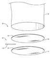
第2のシート66の上に重なった第1のシート60の上面図が図3に示されている。この実施形態では、シート60および66は溶着ライン72によって互いに溶着される。溶着ライン72は、本明細書で論じる他の溶着ラインと同様に、レーザ溶着、音波溶着、熱溶着など、任意の従来の技法を用いて形成され得る。溶着ライン72は、シート60および66の外周縁部または外側縁部を互いに溶着するものとして示されているが、外周縁部の一方もしくは両方から径方向内側にまたは他の位置において形成され得る。やはり図3に示すように、他の溶着ラインをシート60と66との間に作ることによって、4つの別々のスパージャ74A〜74Dが形成される。 A top view of the
例えば、スパージャ74Aは、溶着ライン76Aを形成することによって形成される。溶着ライン76Aは、シート60および/またはシート66の外周縁部に位置するかまたはそれに隣接する第1の位置78Aで開始し、スパージャ74Aに関する所定の経路に沿ってシート60および66の内側に延在し、次いで、第1の位置78Aに隣接するシート60および/またはシート66の外周縁部に位置するかまたはそれに隣接する第2の位置80Aに戻る。溶着ライン76Aはスパージャ経路82aの外周の境界を定め、スパージャ経路82aはシート60と66との間で境界を定められ、部分的に溶着ライン76Aに囲まれた領域である。図示の実施形態では、スパージャ経路82Aは、第1の端部86から反対側の第2の端部88に延在するガス移送通路84Aを備える。位置78Aと80Aとの間かつシート60と66との間の第1の端部86に開口部87Aが形成され、それを通してガスがガス移送通路84A中に供給され得る。スパージャ経路82Aは、ガス移送通路84Aと流体連通する、第2の端部88に形成されたスパージング領域90Aも備える。図示の実施形態では、ガス移送通路84は狭く細長い通路であり、スパージング領域90は拡大された円形領域を形成する。他の構成も使用され得る。 For example, the
複数の穿孔92が、スパージング領域90Aの第1のシート60を貫通して、そのため、ガスがガス移送通路84Aに沿ってスパージング領域90A中に入り、次いで、穿孔92を通って出ることができて、チャンバ40内に配設された流体41内に気泡を形成する。スパージャ74B〜74Dは同様に形成されており、同様の参照符号が同様の要素を識別するために使用されている。この技法を使用することによって、複数の別々のスパージャは容器32上に簡単に形成され得る。スパージャはそれぞれ、任意の所望の位置に配設され得、任意の所望のサイズ、形状、または構成とすることができる。同様に、4つのスパージャ82が示されているが、1、2、3、5、またはそれよりも多い数など、任意の数のスパージャがシート60および66に形成され得ることが理解される。スパージング領域は、最適にスパージングするように、シート60および66にわたって均等に分布され得るか、または定められた位置に配置され得る。例えば、スパージャは混合する手段のすぐ下に配設され得、そのため、ミキサによって作られる流体41の混合または移動が流体41内に気泡を混入するのを助ける。 A plurality of
いくつかの実施形態では、スパージャはそれぞれ、同じ数の穿孔92を有することができ、全ての穿孔92が同じサイズおよび形状とすることができる。代替的実施形態では、穿孔92は、2以上の異なるスパージャ間で異なっていてよい。例えば、異なるスパージャは、異なる状況での性能を最適化するように異なる数、サイズ、および/または形状の穿孔92を有することができる。より大きい穿孔92は、CO2を流体41からストリッピングするのに最適なことがあるより大きい気泡を作り、より小さい穿孔は、流体41を酸素化するのに好ましいことがあるより小さい泡を作る。同様に、穿孔92の数を増加させると、泡が流体を混合しかつ/またはストリッピングもしくは酸素化を強化するのに有用なことがある。他の実施形態では、スパージャ74A〜74Dのうち1または複数が異なる穿孔92の組み合わせを有することができると理解される。例えば、単一のスパージャが、小さい穿孔92と大きい穿孔92の両方を有することができる。一実施形態では、より小さい泡は、典型的には直径が0.8mm未満、0.4mm未満、または0.2mm未満、0.1mm未満の穿孔92から形成され、大きい泡は、典型的には直径が1.5mmを超える、0.8mmを超える、0.4mmを超える、または0.15mmを超える穿孔から形成される。他の直径の穿孔も使用され得る。穿孔のサイズおよび結果として生じる泡は、容器32の意図される使用およびサイズに応じて変わる。例えば、大きい泡は、体積が大きい流体を大型の容器で処理するときは、比較的体積が小さい流体を小型の容器で処理するときよりも典型的にはより大きい。小さい泡のための穿孔の直径と大きい泡のための穿孔の直径との間の相違すなわち差分は、典型的には、少なくとも0.15mm、0.3mm、0.5mm、または1mmであり、しばしば、これらの値の+/−0.1mmまたは+/−0.5mm以内である。他の相違も使用され得る。In some embodiments, each sparger can have the same number of
以下でさらに詳細に論じるように、スパージャ74A〜74Dは、同時に動作することができるか、あるいはマニホルドまたは他のレギュレータが使用され得、そのため、スパージャのうちの1または複数が、他のスパージャが動作していない間に動作され得る。したがって、異なる穿孔92を有する異なるスパージャを有することによって、選ばれたスパージャが、性能を最適化するように異なる状況または時間で使用され得る。 As discussed in more detail below, spargers 74A-74D can operate simultaneously or a manifold or other regulator can be used so that one or more of the spargers operate with other spargers operating. Can be operated while not. Thus, by having different spargers with
いくつかの実施形態では、スパージャ74Aのガス移送通路84Aが必要とされないことが理解される。例えば、穿孔92は、ガス移送通路84Aの上に重なる第1のシート60を貫通して形成されて、ガス移送通路84Aをスパージング領域90Aの一部分に転換することができる。穿孔92が任意の従来の技法を用いて形成され得ることが理解される。例えば、穿孔92は、シートの製造工程の一部として形成され得るか、または後で打ち抜きもしくは他の技法によって作られ得る。一実施形態では、穿孔92を形成するために1または複数のレーザが使用され得る。レーザを使用することの利点は、穿孔92が正確な位置に正確な直径で形成され得、そのため、泡が正確な既定のサイズを有するように形成され得ることである。さらに、穿孔を形成するためにレーザが使用されるときは、レーザによって溶融された材料が穿孔の外周縁部に沿って集まり、それにより、穿孔を補強し、シートの破断の防止を助ける。 It will be appreciated that in some embodiments, the
本発明の一実施形態では、マニホルドが、スパージャ74A〜74Dのうちの1または複数へのガスの流れを制御するために使用され得る。例えば、本発明の特徴を組み込んだマニホルド100の一実施形態が図3に示されている。マニホルド100は、ガス入口ポート104および複数のガス出口ポート106A〜106Dを有する本体102を備える。ガス出口ポート106A〜106Dは、分岐した流動通路108によってガス入口ポート104と並列に連通している。コンプレッサまたは圧縮ガスのキャニスタなどのガス源がガス入口ポート104と流体接続されている。ガスは、空気、酸素、もしくは任意の他のガス、またはガスの組み合わせとすることができる。ガスライン110A〜110Dは、ガス出口ポート106A〜106Dから各スパージャ74A〜74Dそれぞれの第1の端部86のそれぞれ対応する開口部87A〜87Dに延在する。ガスライン110A〜110Dは、シート60と66との間で開口部87A〜87Dにおいて溶着されて、開口部87A〜87Dが閉じられるようにシールすることができる。ガスライン110A〜110Dは、本体102と一体に形成されるかまたは別々に形成されて本体102取り付けられ得る可撓性または剛体のチューブを備えることができる。 In one embodiment of the present invention, a manifold may be used to control gas flow to one or more of the
バルブ112A〜112Dは、本体102に装着され、各ガスライン110A〜110Dへのガスの流れをそれぞれ制御する。一実施形態では、バルブ112A〜112Dは、スパージャ74A〜74Dへのガスの流れを開くか、閉じるか、または制限するために使用され得るソレノイドバルブなどの電気バルブとすることができる。この実施形態では、電気配線114は、それらの動作を制御するためにバルブ112A〜112Dを接続することができる。他の実施形態では、バルブ112A〜112Dは、手動、油圧、空気圧、または別法で操作されるバルブを備えることができる。マニホルド100を使用することによって、異なるスパージャまたはスパージャの異なる組み合わせが、上記で論じたように性能を最適化するために異なる時間に使用され得る。 The
マニホルド100Aの代替的実施形態が図4に示されており、マニホルド100と100Aとの間の同様の要素は同様の参照符号で識別される。マニホルド100Aは本体102を含み、本体102は、これから突出してスパージャ74A〜74Dと連通するガスライン110A〜110Dを有する。マニホルド100Aでは、ガスライン110A〜110Dは、可撓性の配管を備える。さらに、マニホルド100Aは、それぞれガスライン110A〜110Dに装着されたピンチクランプまたはホースクランプの形態のバルブ114A〜114Dを有する。ピンチクランプ114は様々な異なる構成にすることができ、それを通るガスの流れを制御するようにガスライン110A〜110Dを手動で挟むために使用されることが理解される。 An alternative embodiment of
他の代替的実施形態では、マニホルドが必要とされないことが理解される。例えば、図5に示すように、ガスライン110A〜110Dはスパージャ74A〜74Dから延在することができ、ガスライン110A〜110Dにそれぞれ連結されたバルブ114A〜114Dを有することができる。しかし、ガスライン110A〜110Dは、マニホルドの一部である必要はなくまたはそれと接続される必要はなく、所望の場合は別々のガス源に別々に接続され得る。 It will be appreciated that in other alternative embodiments, no manifold is required. For example, as shown in FIG. 5,
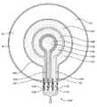
前に論じたように、任意の所望の数、サイズ、形状、および/または構成のスパージャが形成され得る。例えば、3つのスパージャ118A〜118Cがその上に形成された底端壁50の上面図が図6に示されている。さらに、各スパージャ118A〜118Cの外周は、シート60と66との間に形成された溶着ライン120A〜120Cによってそれぞれ形成されている。所望の場合は、単一の溶着ラインが、隣接するスパージャ間の共通の境界を形成することができる。例えば、スパージャ118Bと118Cとの間の共通の境界を形成する溶着ライン120Bが示されている。スパージャ120Aは、スパージャ118Aがシート60および66上でより中心に位置することを除いてスパージャ74Aと同様である。スパージャ118Bは、スパージング領域122Aの周りで湾曲する実質的にC字形のスパージング領域122Bを有する。同様に、スパージャ118Cは、実質的にスパージング領域122Bの周りを囲むスパージング領域122Cを有する。 As discussed previously, any desired number, size, shape, and / or configuration of spargers can be formed. For example, a top view of the
従来のスパージャとは異なり、スパージャ118Cは、第1の端部124および反対側の第2の端部126を有し、第1の端部124および第2の端部126にはそれぞれガスライン110Aおよび110Dが流体接続されている。この構成では、ガスが、スパージャ118Cの互いに反対側の端部でガスライン110Aと110Dの両方を通って供給され得、そのため、ガスがスパージング領域122Cにより均等に提供される。その結果、ガスが、より均一な圧力および流量で全ての穿孔92から出る。さらに、各スパージャ118A〜118Cへのガスの流れは、図示のマニホルド100Aまたは任意の他のタイプのマニホルドによって制御され得る。 Unlike a conventional sparger, the
図6に示す実施形態では、羽根車58(図1)は、スパージャ118Aと垂直に位置合わせされ得、スパージャ118Cは、羽根車58から横方向に離間している。スパージャ118Aは、羽根車58と相互作用し羽根車58によって流体全体にわたって分配されるように小さい泡を作るように設計され得る。羽根車58を用いて小さい泡を分散させることによって、その小さい泡は流体内でより長い滞留時間を有し、それがガスの質量移送を強化する。例えば、泡は流体をより効率的に酸素化することができる。スパージャ118Cは、羽根車58と直接相互作用しないより大きい泡を作る。より大きい泡は、通常、CO2を流体からストリッピングするために使用される。より大きい泡がより小さい泡よりも高い浮力を有するので、より大きい泡に対する羽根車の影響が小さく、したがって、それらを羽根車と位置合わせする必要を無くすことができる。さらに、羽根車は、より大きい泡を分解することができて、それらがCO2をストリッピングするための効率を下げる。さらに、より大きい泡を羽根車と位置合わせすると、羽根車が空洞を作ることがあり、それが流体の混合効率を下げる。しかし、他の実施形態では、スパージャ118Aは、羽根車58によって意図的に分解および分散される大きい泡を作るように設計され得、スパージャ118Cは、羽根車58と直接相互作用しない小さい泡を作る。他の構成も使用され得る。In the embodiment shown in FIG. 6, the impeller 58 (FIG. 1) can be aligned vertically with the sparger 118 </ b> A, and the sparger 118 </ b> C is laterally spaced from the
別の実施形態では、容器内の流体がより均一にスパージングされるように、底端壁50の大部分をカバーする単一のスパージャを有する得ることが望ましい場合がある。例えば、第1の端部134および反対側の第2の端部136を有するスパージャ130が図7に示されており、外周がそれらの間で延在する溶着ライン132Aおよび132Bによって境界を定める。スパージャ130は、細長く、湾曲しながら底端壁50に沿って蛇行する。スパージャ130は、スパージング領域130、すなわち、底端壁50の片側の表面積の少なくとも40%、より一般には少なくとも50%、60%、または80%をカバーする溶着ライン132Aと132Bとの間の領域を有する。他の割合も使用され得る。ガスライン110Aおよび110Bは、スパージャ130の互いに反対側の端部と接続されており、そのため、ガスがスパージャ130の互いに反対側の端部で送出され得る。その結果、ガスは、単一のガスラインしか使用されない場合よりも均等に穿孔92を通って出る。 In another embodiment, it may be desirable to have a single sparger that covers most of the
図8に移ると、代替的一実施形態では、本発明のスパージャは、3枚以上のシートを重ねることによって形成され得る。例えば、1または複数の溶着ラインは、破線141Aによって示されたスパージャをそれらの間に形成するように、シート60をシート66に溶着することができる。同様に、1または複数の溶着ラインは、シート66と140とを互いに溶着してそれらの間に破線141Bで示されるスパージャを形成することができる。開口部142が、シート66と140との間に形成されるスパージャ141Bのスパージング領域を露出するようにシート60を貫通して形成され得る。溶着ラインが3つのシート16、60、および140を全て一緒に同時に溶着してスパージャ141Aおよび/または141Bを形成することができることも理解されよう。ガスライン110Aおよび110Bは、スパージャ141Aおよび141Bにそれぞれ接続されており、それらにガスを送出する。 Turning to FIG. 8, in an alternative embodiment, the sparger of the present invention may be formed by stacking three or more sheets. For example, the one or more weld lines can weld the
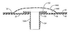
前述の実施形態では、図3の開口部87A〜87Dなどの開口部を通って入る、ガスをスパージャに供給するガスラインがシート60と66との間に形成され得る。この構成は、ガスラインが容器32の側方から径方向外側に突出し、したがって、サポートハウジング12の側方の開口部24(図1)を通って突出することを可能にする。しかし、代替的実施形態では、ガスラインは、底端壁50の底から下に突出し、さらにサポートハウジング12の床22を通って下に突出するように、スパージャと流体接続することができる。例えば、図9に示すように、容器32の底端壁50は、やはり、互いに溶着されてスパージャ144A〜144Cを形成する、第1のシート60を第2のシート66に重ねたものから構成される。詳細には、図10に示す上面図では、溶着ライン146A〜146Cは、シート60と66とを互いに溶着し、それぞれスパージング領域148A〜148Cの外周の境界を定めるように、それぞれ円形パターンに形成される。代替的実施形態では、溶着ライン146A〜146Cが任意の囲繞するパターンで形成され得ることが理解される。スパージャ144A〜144Cはまた、各スパージング領域148の上に重なる第1のシート60を貫通して形成された穿孔92を有する。 In the foregoing embodiment, a gas line may be formed between the
図9および図11に示すように、ポート152Aは、ステム154がシート66の開口部156を通って下に延在するように、第2のシート66の第1の側面68上に装着されたフランジ153を有する。その結果、ポート152Aはスパージャ144Aのスパージング領域148Aと連通する。ポート152Bおよび152Cは、同様に、スパージャ144Bおよび144Cと接続される。図9に示すように、ガスライン110A〜110Cの第1の端部は、それぞれポート152A〜152Cと接続され、ガスライン110A〜110Cの反対側の第2の端部は、マニホルド100と接続される。その結果、マニホルド100は、各スパージャ144A〜144Cの選択的な動作を制御するように使用され得る。さらに、スパージャ144A〜144Cは、任意の所望のサイズ、形状、または構成のものにされ得る。 As shown in FIGS. 9 and 11, the
容器およびスパージャに関する所望の構成に応じて、容器が様々な異なる手順を用いて組み立てられ得ることが理解される。例えば、シート60および66をそれらの所望のサイズに切断する前または後に、穿孔92は、所望の数、サイズ、形状、および位置を有する第1のシート60上に形成され得る。同様に、適用可能な場合は、開口部156が第2のシート66上に形成されポート152がそれに溶着され得る。次に、シート60および66を互いに溶着してスパージャを作るように、シート60と66とが重ねられ、様々な溶着ラインが形成され得る。ポート156が使用されない場合は、ガスラインは、スパージャと連通するようにシート60と66との間に形成された開口部内で溶着され得る。最後に、シート60および66は側壁42に溶着され得る。あるいは、シート60は側壁42に溶着され得、次いで、シートを互いに溶着しスパージャを形成するように第2のシート66は第1のシート60に溶着され得る。さらに他の実施形態では、第1のシート60が側壁42と一体に形成され得るか、または側壁42と第1のシート60が互いに溶着される複数のセクションを備えることができる。これらの構成では、第2のシート66は、その後、第1のシート60と側壁42の組み合わせに溶着されることになる。他の実施形態では、第2のシート66は、側壁42に取り付けられるかまたはそれと一体に形成され得、第1のシート60は、第2のシート66の一部分しかカバーしないより小さいシートまたはより小さい複数のシートを備えることができる。ガスラインが異なるスパージャと接続され、適切な場合はマニホルドがそれに接続されると、容器に接続された全てのガスラインおよびポートが閉じられ、放射線または他の従来の技法によってアセンブリ全体が滅菌される。 It will be appreciated that the container can be assembled using a variety of different procedures, depending on the desired configuration for the container and sparger. For example, before or after cutting
使用を容易にするために、容器アセンブリ13は、サポートハウジング12のコンパートメント20内に降ろされる。次いで、関連のマニホルドおよび/またはガスラインは、図1に示すサポートハウジング12が使用されるときは、開口部24を通ってコンパートメント20を貫通する。図9に示す実施形態では、マニホルドおよびガスラインは、サポートハウジング12Aの床22に形成された細長い開口部24Aを通って下に貫通することができる。両方の実施形態において、プレート158を用いて、マニホルドがそれを通って貫通した後で開口部24または24Aの一部分をカバーするのを助け、開口部のサイズを最小限に抑える。このように開口部をカバーすることは、開口部を通して容器を押そうとする流体によって生じる容器上のストレスを軽減する。容器アセンブリ13は、それが手動で調節されサポートハウジング12内に適切に配置されることを可能にするように、それがサポートハウジング12内に配置された後に、ガスで部分的に膨張され得る。あるいは、容器アセンブリ13は、それが適切な配置のために調節される間に流体で充填され得る。容器アセンブリ13は、その後、バイオリアクタ、発酵槽として、または流体もしくは化学物質を単に処理するために使用され得る。 For ease of use, the
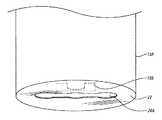
本発明の別の代替的実施形態では、ガスラインは、底端壁50の上部から上に突出し、さらに容器32の上側端部に配置されたポート52(図1)に接続するかまたはそれを通して延在するように、スパージャと流体接続することができる。例えば、図13に示すように、容器32の底端壁50は、やはり、互いに溶着されてスパージャ160を形成する、第1のシート60を第2のシート66に重ねたものから構成される。詳細には、図10に関して前に論じたのと同じように、溶着ライン162が、スパージング領域164の外周の境界を定めるように、シート60と66を互いに円形パターンで溶着することができる。代替的実施形態では、溶着ライン162が任意の囲繞するパターンで形成され得、任意の数の別々のスパージャ160が形成され得ることが理解される。第1のシート60がスパージャ160または複数のスパージャ160を形成するのに十分に大きい必要があるだけであり、第2のシート66と同程度に大きい必要がないことも理解される。スパージャ160はまた、スパージング領域164上に重なる第1のシート60を貫通して形成された穿孔92も含む。 In another alternative embodiment of the present invention, the gas line projects upward from the top of the
ポート152のフランジ153は、ステム154がシート66の開口部を外向きに貫通するように、溶着または接着剤などによって第1のシート60の第2の側面64上に装着される。その結果、ポート152はスパージング領域164と連通する。ガスライン171の第1の端部168は、ポート152のかかりのついた(barbed)端部155と接続されており、ガスライン171の反対側の第2の端部172は、容器32のポート52(図1)の1つと接続されるかまたはそれを外向きに貫通する。ガスライン171がそれに接続するかもしくは外に延在するポート52が、図1に示すように容器32の上側端部に配置され得るか、または側壁42に沿ったもしくは床50上の任意の位置に配置され得ることが理解される。ガスライン171の第2の端部172をポート52に接続する一方法は、2007年6月5日発行の特許文献6に開示されており、その文献は本明細書の一部を構成するものとして援用される。さらに、ガスライン171の第2の端部172は、ガスをスパージャ160に送出するガス源と連通して配置され得る。ガスライン171はまた、底端壁50上に形成された複数の別々のスパージャ160へのガスの流れを制御できるようにマニホルドと接続され得る。 The
本発明のスパージャおよび関連の容器が従来のスパージャに比べて様々な特有の利点を有することが理解される。例えば、本発明のスパージャは、単に2つのシートを互いに溶着することによって簡単に形成され得る。こうした溶着は、容器を形成するのに使用されるのと同じ装備および技法を用いて実現され得る。このように製造が簡単であると、所望のサイズ、向き、構成、位置、数などのスパージャを形成において汎用性を高めて所望の処理パラメータを最適化することができる。さらに、スパージャは、可撓性であり、袋または容器の一部である。これは、アセンブリを損傷する潜在的なリスクなしに、容器とスパージャとの組み合わせが簡単に巻かれるかたまは折り畳まれることを可能にする。巻かれたまたは折り畳まれたアセンブリは、簡単に滅菌、格納、輸送、および剛体のサポートハウジングに組み込まれ得る。袋の底部に複数のスパージャを作ることができると、やはり、異なる目的を達成するために異なる泡サイズおよび数が選択的に作られ得るように、スパージャが異なる穿孔サイズで形成されることも可能にする。さらに、マニホルドを使用することによって、異なるスパージャまたはスパージャ組み合わせの動作が、処理パラメータをさらに最適化するように制御され得る。容器とスパージャとの組み合わせは作製が比較的安価なので、そのアセンブリは、使い捨ての1回使うだけのアイテムとして設計され得、それにより、使用の前後の洗浄および滅菌を無くす。スパージャはまた、床と面一であり、そのため、それらが流体の流れまたは流体内の細胞もしくは微生物の流れを妨げることがない。 It will be appreciated that the spargers and associated containers of the present invention have various unique advantages over conventional spargers. For example, the sparger of the present invention can be formed simply by simply welding two sheets together. Such welding can be accomplished using the same equipment and techniques used to form the container. As described above, when the manufacturing is simple, versatility can be enhanced in forming a sparger having a desired size, orientation, configuration, position, number, etc., and desired processing parameters can be optimized. Furthermore, the sparger is flexible and is part of a bag or container. This allows the container and sparger combination to be easily rolled up or folded without the potential risk of damaging the assembly. The rolled or folded assembly can be easily integrated into a sterilization, storage, transport, and rigid support housing. Once multiple spargers can be made at the bottom of the bag, the spargers can also be formed with different perforation sizes so that different foam sizes and numbers can be selectively made to achieve different objectives To. Further, by using the manifold, the operation of different spargers or sparger combinations can be controlled to further optimize the processing parameters. Because the container and sparger combination is relatively inexpensive to make, the assembly can be designed as a disposable, single use item, thereby eliminating pre- and post-use cleaning and sterilization. Spargers are also flush with the floor so that they do not interfere with the flow of fluid or the flow of cells or microorganisms within the fluid.
本発明は、その精神または本質的な特徴から逸脱することなく他の特定の形態で具体化され得る。説明された実施形態は、あらゆる点で例示的なものであり限定的ではないと解釈されるべきである。したがって、本発明の範囲は、前述の説明ではなく、添付された特許請求の範囲によって示される。請求項の等価物の意味および範囲内に包含される全ての変更がそれらの範囲内に含まれる。 The present invention may be embodied in other specific forms without departing from its spirit or essential characteristics. The described embodiments are to be considered in all respects only as illustrative and not restrictive. The scope of the invention is, therefore, indicated by the appended claims rather than by the foregoing description. All changes that come within the meaning and range of equivalency of the claims are to be embraced within their scope.
Claims (28)
Translated fromJapanese前記第1のポリマーシートを前記第2のポリマーシートに溶着する第1の溶着ラインであって、前記第1の溶着ラインは、前記第1のポリマーシートと前記第2のポリマーシートとの間に形成された第1のスパージャ経路の外周の境界を定め、前記第1のスパージャ経路は、第1の端部から反対側の第2の端部に延在する第1のガス移送通路と、前記第2の端部に形成され前記第1のガス移送通路と連通する第1のスパージング領域と、を備える、第1の溶着ラインと、
ガスが前記第1のスパージング領域から第1の穿孔を通って前記袋のチャンバ中に至ることができるように、前記第1のポリマーシートのうちの前記第1のスパージング領域に重なる部分を貫通して形成された複数の第1の穿孔と
を備えることを特徴とする容器アセンブリ。A flexible bag having an inner surface that delimits a chamber and an outer surface opposite to the chamber, the upper bag having a top wall, a bottom wall, and a surrounding side wall extending therebetween, the bottom wall having a first wall A flexible bag composed of a polymer sheet overlaid on a second polymer sheet;
A first welding line for welding the first polymer sheet to the second polymer sheet,wherein the first welding line is between the first polymer sheet and the second polymer sheet. defines theouter periphery boundaryof the first spargingcatcher pathformed, the first sparger path, a first gas transfer passage extending in a second end opposite the first end, a first sparging area that communicates with the first gas transfer passage formed in said second end, Ruanda first weld line,
Gas passes through thefirst perforationset al or the first sparging area to be able to reach into the chamber of the bag, through the portion overlapping the first sparging area of said first polymer sheet A container assembly comprising a plurality of first perforations formed as described above.
前記第1のポリマーシートのうちの前記第2のスパージング領域に重なる部分を貫通して形成された複数の第2の穿孔と
をさらに備えることを特徴とする請求項1に記載の容器アセンブリ。A second welding line for welding the first polymer sheet to the second polymer sheet, wherein the second sparging region is formed between the first polymer sheet and the second polymer sheet. A second welding line that defines the boundary of
The container assembly according to claim 1, further comprising a plurality of second perforations formed through a portion of the first polymer sheet that overlaps the second sparging region.
前記マニホルドを通って前記第1のスパージング領域に至るガスの流れを調整する第1のバルブと、
前記マニホルドを通って前記第2のスパージング領域に至るガスの流れを調整する第2のバルブと
を備えることを特徴とする請求項10に記載の容器アセンブリ。The manifold is
A first valve that regulates the flow of gas through the manifold to the first sparging region;
Container assembly according to claim 10, characterized in that it comprises a second valve for adjusting the flow of gas leading to the through the manifold second sparging area.
ガス入口ポートおよび複数のガス出口ポートを有する本体であって、前記ガス入口ポートが前記複数のガス出口ポートそれぞれと流体連通する、本体と、
前記第1のスパージング領域および前記ガス出口ポートのうちの第1のものと流体連通する第1のガスラインと、
前記第2のスパージング領域および前記ガス出口ポートのうちの第2のものと流体連通する第2のガスラインと
を備えることを特徴とする請求項10に記載の容器アセンブリ。The manifold is
A body having a gas inlet port and a plurality of gas outlet ports, wherein the gas inlet port is in fluid communication with each of the plurality of gas outlet ports;
A first gas line in fluid communication with the first of the first sparging region and the gas outlet port;
Container assembly according to claim 10, characterized in that it comprises a second gas line for the second one in fluid communication with one of said second sparging region and the gas exit port.
前記第1のポリマーシートを前記第2のポリマーシートに溶着する第1の溶着ラインであって、前記第1のポリマーシートと前記第2のポリマーシートとの間に形成された第1のスパージング領域の境界を定め、複数の第1の穿孔が前記第1のポリマーシートのうちの前記第1のスパージング領域に重なる部分を貫通して形成される、第1の溶着ラインと、
前記第1のポリマーシートを前記第2のポリマーシートに溶着する第2の溶着ラインであって、前記第1のポリマーシートと前記第2のポリマーシートとの間に形成された第2のスパージング領域の境界を定め、複数の第2の穿孔が前記第1のポリマーシートのうちの前記第2のスパージング領域に重なる部分を貫通して形成された、第2の溶着ラインと
を備えることを特徴とする容器アセンブリ。A flexible bag having an inner surface delimiting a chamber and an opposite outer surface, the flexible bag having a bottom end wall composed of a first polymer sheet superimposed on a second polymer sheet A bag,
A first welding line for welding the first polymer sheet to the second polymer sheet, the first sparging region formed between the first polymer sheet and the second polymer sheet A first welding line, wherein a plurality of first perforations are formed through a portion of the first polymer sheet that overlaps the first sparging region;
A second welding line for welding the first polymer sheet to the second polymer sheet, wherein the second sparging region is formed between the first polymer sheet and the second polymer sheet. A plurality of second perforations comprising a second weld line formed through a portion of the first polymer sheet that overlaps the second sparging region. Container assembly.
前記マニホルドを通って前記第1のスパージング領域に至るガスの流れを調整する第1のバルブと、
前記マニホルドを通って前記第2のスパージング領域に至るガスの流れを調整する第2のバルブと
を備えることを特徴とする請求項18に記載の容器アセンブリ。The manifold is
A first valve that regulates the flow of gas through the manifold to the first sparging region;
The container assembly of claim18 , further comprising a second valve that regulates a gas flow through the manifold to the second sparging region.
前記第2のポリマーシートと接続され前記第2のスパージング領域と連通する第2のポートと
をさらに備えることを特徴とする請求項18に記載の容器アセンブリ。A first port connected to the second polymer sheet and in communication with the first sparging region;
The container assembly of claim18 , further comprising a second port connected to the second polymer sheet and in communication with the second sparging region.
ガス入口ポートおよび複数のガス出口ポートを有する本体であって、前記ガス入口ポートが前記複数のガス出口ポートそれぞれと流体連通する、本体と、
前記第1のポートから前記ガス出口ポートのうちの第1のものまで延在する第1のガスラインと、
前記第2のポートから前記ガス出口ポートのうちの第2のものまで延在する第2のガスラインと
を備えることを特徴とする請求項22に記載の容器アセンブリ。The manifold is
A body having a gas inlet port and a plurality of gas outlet ports, wherein the gas inlet port is in fluid communication with each of the plurality of gas outlet ports;
A first gas line extending from the first port to a first one of the gas outlet ports;
The container assembly of claim 22, characterized in that it comprises a second gas line extending to a second one of said gas outlet port from the second port.
前記第1のポリマーシートを前記第2のポリマーシートに溶着する少なくとも1つの溶着ラインであって、前記第1のポリマーシートと前記第2のポリマーシートとの間に形成され第1の端部と反対側の第2の端部との間で延在する細長いスパージング領域の境界を定め、複数の穿孔が前記第1のポリマーシートのうちの前記第1のスパージング領域に重なる部分を貫通して形成される、前記少なくとも1つの溶着ラインと、
前記スパージング領域の前記第1の端部と接続された第1のガスラインと、
前記スパージング領域の第2の端部と接続された第2のガスラインと
を備えることを特徴とする容器アセンブリ。A flexible bag having an inner surface delimiting a chamber and an opposite outer surface, the flexible bag having a bottom end wall composed of a first polymer sheet superimposed on a second polymer sheet A bag,
At least one welding line for welding the first polymer sheet to the second polymer sheet, the first end being formed between the first polymer sheet and the second polymer sheet; Bounding an elongated sparging region that extends between the opposite second end, and a plurality of perforations formed through a portion of the first polymer sheet that overlaps the first sparging region Said at least one welding line;
A first gas line connected to the first end of the sparging region;
A container assembly comprising: a second gas line connected to a second end of the sparging region.
Applications Claiming Priority (3)
| Application Number | Priority Date | Filing Date | Title |
|---|---|---|---|
| US201161541913P | 2011-09-30 | 2011-09-30 | |
| US61/541,913 | 2011-09-30 | ||
| PCT/US2012/058086WO2013049692A1 (en) | 2011-09-30 | 2012-09-28 | Container with film sparger |
Publications (2)
| Publication Number | Publication Date |
|---|---|
| JP2014534808A JP2014534808A (en) | 2014-12-25 |
| JP6101698B2true JP6101698B2 (en) | 2017-03-22 |
Family
ID=47178864
Family Applications (1)
| Application Number | Title | Priority Date | Filing Date |
|---|---|---|---|
| JP2014533432AActiveJP6101698B2 (en) | 2011-09-30 | 2012-09-28 | Container with film sparger |
Country Status (7)
| Country | Link |
|---|---|
| US (4) | US9643133B2 (en) |
| EP (1) | EP2760571B1 (en) |
| JP (1) | JP6101698B2 (en) |
| CN (2) | CN106635740B (en) |
| BR (1) | BR112014007807B1 (en) |
| IN (1) | IN2014DN02477A (en) |
| WO (1) | WO2013049692A1 (en) |
Families Citing this family (49)
| Publication number | Priority date | Publication date | Assignee | Title |
|---|---|---|---|---|
| US8603805B2 (en) | 2005-04-22 | 2013-12-10 | Hyclone Laboratories, Inc. | Gas spargers and related container systems |
| DE102009052670B4 (en)* | 2009-11-12 | 2017-10-05 | Sartorius Stedim Biotech Gmbh | Fumigation device for bioreactors |
| US8455242B2 (en) | 2010-02-22 | 2013-06-04 | Hyclone Laboratories, Inc. | Mixing system with condenser |
| US9073650B2 (en) | 2011-07-11 | 2015-07-07 | Life Technologies Corporation | Fluid manifold systems |
| US9376655B2 (en) | 2011-09-29 | 2016-06-28 | Life Technologies Corporation | Filter systems for separating microcarriers from cell culture solutions |
| JP6101698B2 (en) | 2011-09-30 | 2017-03-22 | ライフ テクノロジーズ コーポレイション | Container with film sparger |
| US9839886B2 (en) | 2012-04-06 | 2017-12-12 | Life Tehnologies Corporation | Fluid mixing system with flexible drive line and foldable impeller |
| US10232324B2 (en)* | 2012-07-12 | 2019-03-19 | Applied Materials, Inc. | Gas mixing apparatus |
| US9481477B2 (en) | 2012-09-17 | 2016-11-01 | Life Technologies Corporation | Fluid manifold system with rotatable port assembly |
| JP2016536122A (en)* | 2013-10-30 | 2016-11-24 | イー・エム・デイー・ミリポア・コーポレイシヨン | Modular aeration equipment |
| BR112016016446B1 (en) | 2014-01-16 | 2022-02-15 | Life Technologies Corporation | FOAM SENSOR ASSEMBLY, FOAM SENSOR SYSTEM AND METHOD FOR CONTROLLING FOAM INSIDE A REACTOR |
| JP6585615B2 (en) | 2014-03-21 | 2019-10-02 | ライフ テクノロジーズ コーポレイション | Condenser system for fluid treatment system |
| WO2015142405A1 (en) | 2014-03-21 | 2015-09-24 | Life Technologies Corporation | Gas filter systems for fluid processing systems |
| US20150290597A1 (en)* | 2014-04-09 | 2015-10-15 | Therapeutic Proteins International, LLC | Aeration device for bioreactors |
| SG11201610514SA (en)* | 2014-06-03 | 2017-02-27 | Acd Pharmaceuticals As | Bioreactor and uses thereof |
| JP6409360B2 (en)* | 2014-06-24 | 2018-10-24 | 大日本印刷株式会社 | Culture device and culture bag |
| US9079690B1 (en) | 2014-06-26 | 2015-07-14 | Advanced Scientifics, Inc. | Freezer bag, storage system, and method of freezing |
| US9457306B2 (en) | 2014-10-07 | 2016-10-04 | Life Technologies Corporation | Regulated vacuum off-gassing of gas filter for fluid processing system and related methods |
| US9533900B2 (en)* | 2014-10-30 | 2017-01-03 | Wells Tudor, Llc | Aerator/digester for water treatment |
| US10059918B2 (en) | 2015-03-31 | 2018-08-28 | Heliae Development Llc | Method of vitally supporting microalgae in a flexible bioreactor |
| US10184105B2 (en)* | 2015-03-31 | 2019-01-22 | Heliae Development Llc | Flexible bioreactor and support structure method |
| US10047337B2 (en) | 2015-03-31 | 2018-08-14 | Heliae Development Llc | Method of mixotrophic culturing of microalgae in a flexible bioreactor |
| US10125346B2 (en) | 2015-03-31 | 2018-11-13 | Heliae Development Llc | Bioreactor sterilization method for multiple uses |
| US10184099B2 (en)* | 2015-03-31 | 2019-01-22 | Heliae Development Llc | Flexible bioreactor and support structure system |
| US9937472B2 (en)* | 2015-05-07 | 2018-04-10 | Techmetals, Inc. | Assembly operable to mix or sparge a liquid |
| JP6611092B2 (en)* | 2015-05-28 | 2019-11-27 | エイブル株式会社 | Sparger |
| WO2017116910A1 (en) | 2015-12-29 | 2017-07-06 | Life Technologies Corporation | Flexible bioprocessing container with partial dividing partition |
| KR102649446B1 (en) | 2015-12-29 | 2024-03-20 | 라이프 테크놀로지스 코포레이션 | Fluid mixing system and method of use with laterally displaced flexible drive lines |
| WO2017194138A1 (en)* | 2016-05-12 | 2017-11-16 | Hewlett-Packard Development Company, L.P. | Build material container, and collection tube structure |
| WO2018069578A1 (en) | 2016-10-14 | 2018-04-19 | Teknologian Tutkimuskeskus Vtt Oy | Cultivation unit and set for cultivating cells |
| US11293000B2 (en)* | 2016-10-27 | 2022-04-05 | Field Energy Llc | Sterile heterotrophic growth bioreactor |
| WO2018102566A1 (en) | 2016-12-01 | 2018-06-07 | Life Technologies Corporation | Microcarrier filter bag assemblies and methods of use |
| US11124754B2 (en)* | 2017-05-30 | 2021-09-21 | Nextern, Inc. | Pressure-controlled apparatus for optimal cellular growth |
| US11179684B2 (en)* | 2017-09-20 | 2021-11-23 | New Jersey Institute Of Technology | System, device, and method to manufacture nanobubbles |
| US11584910B2 (en) | 2018-01-17 | 2023-02-21 | Life Technologies Corporation | System and method for cell culture scaling |
| US11524270B2 (en) | 2018-04-27 | 2022-12-13 | Baxter International Inc. | Method of mixing a pharmaceutical solution and mixing system |
| JP2021526388A (en) | 2018-05-30 | 2021-10-07 | ライフ テクノロジーズ コーポレーション | Fluid mixer control system and method |
| GB2576913A (en)* | 2018-09-06 | 2020-03-11 | Trans Ocean Bulk Logistics Ltd | Flexible tank with a mixing member |
| WO2020070688A1 (en)* | 2018-10-03 | 2020-04-09 | Pluristem Ltd. | Modular bioreactor |
| KR102610827B1 (en) | 2018-12-20 | 2023-12-07 | 어플라이드 머티어리얼스, 인코포레이티드 | Method and apparatus for providing improved gas flow to the processing volume of a processing chamber |
| US12324895B2 (en)* | 2019-11-08 | 2025-06-10 | Global Life Sciences Solutions Usa Llc | Sparger device for a bioprocessing system and method of manufacturing a sparger device |
| BR112022023832A2 (en)* | 2020-05-28 | 2022-12-20 | Solugen Inc | REACTOR SYSTEM, SPRINKLER ASSEMBLY FOR A REACTOR, AND METHOD FOR PROVIDING A GAS TO A FLUID INSIDE A REACTOR |
| US11771623B2 (en)* | 2021-03-02 | 2023-10-03 | West Pharmaceutical Services, Inc. | Container for a pharmaceutical composition |
| EP4323093B1 (en)* | 2021-04-16 | 2025-08-06 | EMD Millipore Corporation | Single use flexible sparger |
| AU2022282876B2 (en)* | 2021-05-27 | 2025-08-14 | Flsmidth A/S | Membrane spargers for gravity separators and flotation machines |
| EP4324905A1 (en)* | 2022-08-19 | 2024-02-21 | Sartorius Stedim Biotech GmbH | Bioreactor system with gassing system |
| EP4587549A2 (en) | 2022-09-15 | 2025-07-23 | Life Technologies Corporation | Bioreactors operable in static and dynamic modes and methods of use |
| JP2025531622A (en)* | 2022-09-28 | 2025-09-22 | グローバル・ライフ・サイエンシズ・ソリューションズ・ユーエスエー・エルエルシー | Apparatus, system, and method for filtering waste in rocker bioreactors |
| CN120202286A (en)* | 2022-11-30 | 2025-06-24 | 康宁股份有限公司 | Cell culture dish containing a two-dimensional negligible volume bubbler |
Family Cites Families (214)
| Publication number | Priority date | Publication date | Assignee | Title |
|---|---|---|---|---|
| US1471332A (en) | 1923-10-23 | Apparatus for treating liquids with gases | ||
| US1269189A (en) | 1917-05-31 | 1918-06-11 | Halbert L Kadish | Method of recovering fertilizing material from tannery waste liquids. |
| US1505204A (en) | 1922-03-16 | 1924-08-19 | Thomas J Kiernan | Carbonator |
| US2259243A (en) | 1938-02-05 | 1941-10-14 | Mining Process & Patent Co | Flotation apparatus and method |
| US2341115A (en)* | 1940-01-06 | 1944-02-08 | Durite Plastics Inc | Art of making synthetic resins |
| US2341114A (en)* | 1943-02-16 | 1944-02-08 | Novak Milan | Disposable filter for blood and plasma transfusions |
| US2865618A (en) | 1956-01-30 | 1958-12-23 | Arthur S Abell | Water aerator |
| NL111984C (en) | 1958-12-22 | |||
| US3184395A (en) | 1962-10-01 | 1965-05-18 | John H Brewer | Apparatus and method for culturing aerobic microorganisms |
| US3207420A (en) | 1964-05-19 | 1965-09-21 | Octaviano D Navarrete-Kindelan | Container |
| US3445237A (en) | 1966-06-28 | 1969-05-20 | Lester Gidge | Preshaped cartridge for,and method of packaging,percolator ground coffee |
| US3545671A (en) | 1967-02-14 | 1970-12-08 | Eugene Ross Lab Inc | Apparatus for and method of collecting,storing,separating and dispensing blood and blood components |
| US3608709A (en) | 1969-09-08 | 1971-09-28 | Wayne Rogers V | Multiple compartment package |
| US3647397A (en) | 1969-11-19 | 1972-03-07 | Charles M Coleman | Reagent solution preparation |
| US3682168A (en) | 1970-06-10 | 1972-08-08 | Ahldea Corp | Sterile liquid entraining system |
| US3701433A (en)* | 1970-11-10 | 1972-10-31 | Pall Corp | Filter for use in the filtration of blood |
| US3702619A (en)* | 1971-01-28 | 1972-11-14 | Shell Oil Co | In-line mixing apparatus for gases |
| CH525704A (en) | 1971-03-01 | 1972-07-31 | Kaelin J R | Ventilation device for liquids and methods for their operation |
| IT1031424B (en) | 1974-02-14 | 1979-04-30 | Licentia Gmbh | COUNTING DEVICE COMPOSED OF COUNTER AND CATE NA MAGNET CA COUNTING |
| US4036919A (en) | 1974-06-26 | 1977-07-19 | Inhalation Therapy Equipment, Inc. | Nebulizer-humidifier system |
| US4157965A (en)* | 1975-01-20 | 1979-06-12 | Bentley Laboratories, Inc. | Blood treating device |
| US4061698A (en) | 1975-04-18 | 1977-12-06 | Aerwey Laboratories, Inc. | Humidifier-nebulizer apparatus |
| US4012471A (en) | 1975-06-06 | 1977-03-15 | Kunkle Jr George E | Disposable container |
| US4012473A (en) | 1975-07-16 | 1977-03-15 | Arbrook, Inc. | Nebulizer-humidifier |
| US4025590A (en) | 1976-06-10 | 1977-05-24 | Victor Igich | Self-sealing humidifier for inhalation therapy |
| US4493637A (en) | 1978-02-15 | 1985-01-15 | Thermics Corporation Liquidating Trust | Fossil fuel catalyst generator |
| US4204774A (en) | 1979-02-26 | 1980-05-27 | Bruyne Norman A De | Synchronous stirrer |
| US4250039A (en)* | 1979-05-07 | 1981-02-10 | Wire Cloth Products, Inc. | Transmission filter |
| JPS5642584A (en)* | 1979-09-18 | 1981-04-20 | Asahi Chem Ind Co Ltd | Cell cultivation method |
| CH651587A5 (en) | 1980-11-18 | 1985-09-30 | Chemap Ag | METHOD AND DEVICE FOR SUBMERSE CELL CULTURE. |
| CH655533B (en) | 1981-08-14 | 1986-04-30 | ||
| US4402402A (en) | 1981-10-14 | 1983-09-06 | Pike Brian R | Barrier seal multiple-compartment package |
| CS231615B1 (en) | 1981-12-29 | 1984-12-14 | Vladislav Vlcek | Method of cultivation of cells of higher organism and device to perform the method |
| FI71102C (en) | 1982-02-25 | 1986-11-24 | Fluilogic Systems Oy | REAGENSFOERPACKNING |
| US4635620A (en) | 1982-04-23 | 1987-01-13 | Ricchio Dominic A | Method for improved water therapy |
| JPS58224683A (en) | 1982-06-22 | 1983-12-27 | Mitsubishi Heavy Ind Ltd | Fermentation tank |
| US4458811A (en) | 1983-04-21 | 1984-07-10 | Abbott Laboratories | Compartmented flexible solution container |
| SE8306190L (en) | 1983-11-10 | 1985-05-11 | Ivar Wergeland | PROCEDURE AND DEVICE FOR IMPROVED OBJECTIVES OF BIOLOGICAL CULTURES |
| US4581143A (en)* | 1984-08-03 | 1986-04-08 | Pepper Iii Harry | Fixed film process for the treatment of waste water utilizing interfacial oxygen transfer |
| JPS6167476A (en) | 1984-09-10 | 1986-04-07 | Shibata Hario Glass Kk | Apparatus for vegetable cell culture |
| US4740202A (en) | 1984-10-12 | 1988-04-26 | Haemonetics Corporation | Suction collection device |
| US4668632A (en) | 1985-02-06 | 1987-05-26 | Vxr, Inc. | Sparger and apparatus for and method of growing cells |
| US4727040A (en) | 1985-03-01 | 1988-02-23 | New Brunswick Scientific Co., Ltd. | Sparger for fermentation and tissue culturing vessels |
| WO1986007254A1 (en) | 1985-06-14 | 1986-12-18 | Material Engineering Technology Laboratory, Inc. | Medical liquid container and method of manufacturing same |
| JPS62160899A (en) | 1986-01-10 | 1987-07-16 | Hitachi Ltd | Trunk selection system |
| NZ218971A (en) | 1986-01-21 | 1989-05-29 | Mitsui Toatsu Chemicals | Porous polyolefin films and their preparation |
| GB8617569D0 (en) | 1986-07-18 | 1986-08-28 | Davidson J F | Impellers |
| EP0258795B1 (en) | 1986-08-27 | 1993-11-03 | Kawasumi Laboratories, Inc. | A method for cultivating cells and an instrument therefor |
| JPS6384483A (en) | 1986-09-30 | 1988-04-15 | Ebara Res Co Ltd | Culture apparatus |
| US4869398A (en) | 1986-11-25 | 1989-09-26 | Life Technologies, Inc. | Liquid container delivery and storage system |
| GB2202549A (en) | 1987-03-20 | 1988-09-28 | Philip John Whitney | Foldable fermenter |
| US5100376A (en) | 1987-08-26 | 1992-03-31 | Blake Joseph W Iii | Body-cavity drainage and autotransfusion system |
| CH675368A5 (en) | 1987-09-10 | 1990-09-28 | Roshard Ag | Injecting fine gas bubbles into liq. - via pores in boundary structure with compsn. to repel liq. |
| US4869852A (en) | 1988-01-22 | 1989-09-26 | Mooers Products, Inc. | Diffuser apparatus |
| IL86442A (en) | 1988-05-19 | 1992-02-16 | Plant Biotec Ltd | Air lift fermenter formed from flexible plastic sheets |
| JPH0231825A (en) | 1988-07-20 | 1990-02-01 | Kanai Hiroyuki | Bubble generator |
| US5416022A (en)* | 1988-08-10 | 1995-05-16 | Cellex Biosciences, Inc. | Cell culture apparatus |
| US5139946A (en) | 1988-11-02 | 1992-08-18 | Du Pont Merck Pharmaceutical Company | Dot matrix membrane cell expansion |
| JP2690144B2 (en) | 1989-04-24 | 1997-12-10 | 哲哉 峠 | Membrane cell culture device |
| JPH0310675A (en) | 1989-06-09 | 1991-01-18 | Shimadzu Corp | Bag for cell culture |
| JPH07114686B2 (en) | 1989-06-26 | 1995-12-13 | 明治乳業株式会社 | Circulating culture device |
| JPH03242297A (en) | 1990-02-19 | 1991-10-29 | Komatsu Ltd | Fine bubble generation air diffuser |
| US4981623A (en) | 1990-03-12 | 1991-01-01 | Aquatec, Inc. | Diffuser for aeration basin |
| US5183595A (en) | 1990-04-20 | 1993-02-02 | Schuessler Karl H | Device for gassing liquids |
| US5635387A (en) | 1990-04-23 | 1997-06-03 | Cellpro, Inc. | Methods and device for culturing human hematopoietic cells and their precursors |
| JPH04215927A (en) | 1990-05-04 | 1992-08-06 | Puff Pac Ind Inc | Package system |
| US5422043A (en) | 1990-08-31 | 1995-06-06 | Burris; William A. | Diffuser and diffusing method using dual surface tensions |
| AU1417392A (en) | 1991-03-05 | 1992-10-06 | Schur Consumer Products A/S | A freezing mould bag |
| GB9109713D0 (en) | 1991-05-03 | 1991-06-26 | Todd John J | Apparatus for the gasification of liquids |
| US5695489A (en) | 1991-09-30 | 1997-12-09 | Baxter International Inc. | Blood filtering container |
| JPH05219834A (en)* | 1992-02-14 | 1993-08-31 | Fumiko Kobayashi | Disposable culture bag and culture process |
| JP3217451B2 (en) | 1992-06-09 | 2001-10-09 | 藤森工業株式会社 | Shaking culture method of microorganisms, plant cells or animal cells |
| US5287961A (en) | 1992-10-23 | 1994-02-22 | W.R. Grace & Co.-Conn. | Multi-compartment package having improved partition strip |
| JPH06153902A (en) | 1992-11-19 | 1994-06-03 | Shibata Hario Glass Kk | Culture tank |
| KR100299630B1 (en) | 1993-01-19 | 2001-11-22 | 데이비드 씨. 맥키, 토마스 제어. 시바티노 | Multi Chamber Container |
| US5376271A (en) | 1993-03-29 | 1994-12-27 | Morgan, Jr.; H. William | Liquid filtration unit |
| JPH078264A (en) | 1993-06-21 | 1995-01-13 | Tokyo Gas Co Ltd | Bioreactor |
| US5443985A (en) | 1993-07-22 | 1995-08-22 | Alberta Research Council | Cell culture bioreactor |
| IT1260685B (en) | 1993-09-29 | 1996-04-22 | Sorin Biomedica Spa | BLOOD CONTAINMENT DEVICE |
| US5578459A (en) | 1993-11-24 | 1996-11-26 | Abbott Laboratories | Method and apparatus for collecting a cell sample from a liquid specimen |
| JP3531956B2 (en) | 1993-12-07 | 2004-05-31 | 藤森工業株式会社 | Microbial, plant or animal shaking culture device and culture method |
| US6422397B1 (en) | 1993-12-22 | 2002-07-23 | Baxter International, Inc. | Blood collection systems including an integral, flexible filter |
| DE4410876A1 (en) | 1994-03-29 | 1995-10-05 | Fresenius Ag | Medical multi-chamber bag and process for its manufacture |
| US5431498A (en) | 1994-04-11 | 1995-07-11 | Thomson Industries, Inc. | Linear motion bearing |
| US5714384A (en) | 1994-06-28 | 1998-02-03 | Wilson; John R. | Compartmentalized tissue culture bag |
| US5693537A (en) | 1994-06-28 | 1997-12-02 | Wilson; John R. | Compartmentalized tissue culture flask |
| US5547108A (en) | 1994-08-02 | 1996-08-20 | Pall Corporation | Expressor |
| JP2887737B2 (en) | 1994-12-24 | 1999-04-26 | 財団法人電力中央研究所 | Bioreactor |
| CN1044334C (en) | 1994-12-28 | 1999-07-28 | 黄为民 | Stirring caldron |
| EP0725134A3 (en) | 1995-02-03 | 1998-05-13 | NPBI Nederlands Produktielaboratorium voor Bloedtransfusieapparatuur en Infusievloeistoffen B.V. | Flexible bioreactor for therapeutic cells |
| CA2214384C (en) | 1995-03-30 | 2007-06-26 | Martin L. Wolf | Compartmentalized tissue culture bag |
| FR2734173B1 (en) | 1995-05-19 | 1997-08-01 | Rhone Poulenc Chimie | REACTOR FOR IMPLEMENTING CHEMICAL REACTIONS INVOLVING BIOMASS |
| US5653794A (en) | 1995-12-01 | 1997-08-05 | Scm Chemicals, Inc. | Silane treated inorganic pigments |
| US5763267A (en)* | 1996-04-16 | 1998-06-09 | Advanced Tissue Sciences | Apparatus for the large scale growth and packaging of cell suspensions and three-dimensional tissue cultures |
| US5910138A (en) | 1996-05-13 | 1999-06-08 | B. Braun Medical, Inc. | Flexible medical container with selectively enlargeable compartments and method for making same |
| US6071005A (en) | 1996-06-11 | 2000-06-06 | Merck & Co., Inc. | Disposable storage, transport and resuspension system |
| IL119310A (en) | 1996-09-26 | 1999-07-14 | Metabogal Ltd | Cell/tissue culturing device and method |
| JP4042167B2 (en) | 1996-09-30 | 2008-02-06 | 藤森工業株式会社 | Shake culture container |
| US5925293A (en)* | 1996-10-04 | 1999-07-20 | General Signal Corporation | Mixer sparging apparatus |
| US5799830A (en) | 1996-11-08 | 1998-09-01 | Carroll; David C. | Pressure vessel access port |
| AUPO357396A0 (en) | 1996-11-12 | 1996-12-05 | Aquatec-Maxcon Pty Ltd | A diffuser for aerating a fluid |
| US5858283A (en) | 1996-11-18 | 1999-01-12 | Burris; William Alan | Sparger |
| JPH10150972A (en) | 1996-11-19 | 1998-06-09 | Fujimori Kogyo Kk | Shaking culture vessel |
| US6146891A (en) | 1997-01-31 | 2000-11-14 | Schering Corporation | Methods for cultivating cells and propagating viruses |
| US6117801A (en) | 1997-03-27 | 2000-09-12 | E. I. Du Pont De Nemours And Company | Properties for flash-spun products |
| US6219871B1 (en) | 1997-04-14 | 2001-04-24 | Max B. Frederick | Washing apparatus and method utilizing flexible container to improve cleaning efficiency and minimize space occupancy |
| US6146875A (en)* | 1997-05-02 | 2000-11-14 | Ward; N. Robert | Method for culturing microorganisms in prefilled flexible containers |
| DE19719751A1 (en) | 1997-05-10 | 1998-11-12 | Augustinus Dr Med Bader | Device for growing and / or treating cells |
| JPH10313718A (en) | 1997-05-22 | 1998-12-02 | Toshiba Eng & Constr Co Ltd | Apparatus and method for culturing plant pieces |
| US5941635A (en) | 1997-06-11 | 1999-08-24 | Hyclone Labortories, Inc. | Mixing block for resuspension system |
| US6083587A (en) | 1997-09-22 | 2000-07-04 | Baxter International Inc. | Multilayered polymer structure for medical products |
| US6086574A (en) | 1997-11-21 | 2000-07-11 | Hyclone Laboratories, Inc. | Fluid delivery systems with diptube connector |
| US6251295B1 (en) | 1998-01-08 | 2001-06-26 | Nexell Therapeutics Inc. | Method for recirculation washing of blood cells |
| US6398195B1 (en) | 1998-04-10 | 2002-06-04 | Grt, Inc. | Method of and apparatus for producing sub-micron bubbles in liquids and slurries |
| US6068775A (en) | 1998-04-13 | 2000-05-30 | Circe Biomedical, Inc. | Removal of agent from cell suspension |
| JPH11299478A (en) | 1998-04-17 | 1999-11-02 | Seitai Kagaku Kenkyukai | Analysis of metabolism of medicine and instrument therefor |
| WO1999067014A1 (en)* | 1998-06-23 | 1999-12-29 | Red Valve Company, Inc. | Fine bubble diffuser |
| US6099734A (en) | 1998-07-08 | 2000-08-08 | Baxter International Inc. | Apparatus, membranes and methods for removing organic compounds from a biological fluid |
| FR2781202B1 (en) | 1998-07-16 | 2001-01-12 | Stedim Sa | POCKETS FOR BIO-PHARMACEUTICAL FLUID PRODUCTS |
| US6245555B1 (en) | 1998-09-01 | 2001-06-12 | The Penn State Research Foundation | Method and apparatus for aseptic growth or processing of biomass |
| AUPP754398A0 (en)* | 1998-12-04 | 1999-01-07 | Morrison, Michael | Method and apparatus for compsting |
| US6432698B1 (en)* | 1999-01-06 | 2002-08-13 | Rutgers, The State University | Disposable bioreactor for culturing microorganisms and cells |
| KR100329019B1 (en) | 1999-04-13 | 2002-03-18 | 윤덕용 | Method for Manufacturing Organic Acid by High-Efficiency Fermentation |
| AT410059B (en) | 1999-05-04 | 2003-01-27 | Aquaconsult Anlagenbau Gmbh | DEVICE FOR FASTENING A PERFORATED MEMBRANE TO A PLATE, MEMBRANE AND PROFILE BAR FOR THIS |
| USH1989H1 (en) | 1999-05-14 | 2001-09-04 | Kimberly-Clark Worldwide, Inc. | Microporous films having zoned breathability |
| DE29909312U1 (en) | 1999-05-27 | 1999-08-12 | Ekato Rühr- und Mischtechnik GmbH, 79650 Schopfheim | Agitator |
| FR2797887B1 (en) | 1999-08-25 | 2002-01-25 | Rech S Tech Modernes S A | PACKAGING DEVICE FOR BIOLOGICAL USE, ESPECIALLY FOR CELL CULTURE |
| US6464211B1 (en) | 1999-08-31 | 2002-10-15 | United States Filter Corporation | Diffuser assembly |
| EP2290050B1 (en) | 1999-09-08 | 2012-06-13 | Levitronix Technologies, LLC | Bioreactor |
| FR2799138B1 (en) | 1999-10-05 | 2002-02-08 | Opifex | REACTOR FOR THE PRODUCTION OF CELL CULTURES OR MICROORGANISMS OR FOR THE SOLUTION OR SUSPENSION OF POWDER IN A LIQUID MEDIUM |
| CA2391019C (en) | 1999-11-10 | 2006-10-24 | Scholle Corporation | Collapsible bag for dispensing liquids and method |
| US6969367B2 (en) | 2000-02-02 | 2005-11-29 | Xepmed, Inc. | Extracorporeal pathogen reduction system |
| WO2001058756A2 (en) | 2000-02-14 | 2001-08-16 | Aerovironment Inc. | Aircraft |
| US20030119185A1 (en) | 2000-02-24 | 2003-06-26 | Xcyte Therapies, Inc. | Activation and expansion of cells |
| JP2001258547A (en) | 2000-03-22 | 2001-09-25 | Uniflows Co Ltd | Film container for koji making and pure culture ventilated koji making apparatus using the same |
| US6632658B1 (en)* | 2000-08-18 | 2003-10-14 | Levitronix Llc | Bioreactor and method for fluidly suspending a product |
| JP2002136570A (en) | 2000-08-24 | 2002-05-14 | Otsuka Pharmaceut Factory Inc | Medical double chamber container |
| JP2002101867A (en) | 2000-10-02 | 2002-04-09 | Fujimori Kogyo Co Ltd | Culture vessel |
| IL155268A0 (en) | 2000-10-09 | 2003-11-23 | Levtech Inc | Systems using a levitating, rotating pumping or mixing element and related methods |
| US6642019B1 (en) | 2000-11-22 | 2003-11-04 | Synthecan, Inc. | Vessel, preferably spherical or oblate spherical for growing or culturing cells, cellular aggregates, tissues and organoids and methods for using same |
| US6390456B1 (en) | 2000-11-30 | 2002-05-21 | Sen-Yung Lee | Bubble generating device |
| CA2437391C (en) | 2001-02-06 | 2010-04-20 | Levtech, Inc. | Apparatus and method for mixing materials sealed in a container under sterile conditions |
| US6544788B2 (en) | 2001-02-15 | 2003-04-08 | Vijay Singh | Disposable perfusion bioreactor for cell culture |
| US20020131654A1 (en) | 2001-03-19 | 2002-09-19 | Smith Sidney T. | Large volume flexible container |
| US6649405B2 (en) | 2001-05-02 | 2003-11-18 | Growing Solutions, Inc. | Compost tea system |
| US6884866B2 (en) | 2001-10-19 | 2005-04-26 | Avant Immunotherapeutics, Inc. | Bulk drying and the effects of inducing bubble nucleation |
| US20030077466A1 (en) | 2001-10-19 | 2003-04-24 | Smith Sidney T. | Multilayered polymer structure |
| US6923567B2 (en) | 2002-04-12 | 2005-08-02 | Hynetics Llc | Mixing tank assembly |
| US6908223B2 (en) | 2002-04-12 | 2005-06-21 | Hynetics Llc | Systems for mixing liquid solutions and methods of manufacture |
| RU2220917C1 (en) | 2002-05-14 | 2004-01-10 | Общество с ограниченной ответственностью "Научно-производственное предприятие Патфил" | Aeration system |
| US6712963B2 (en)* | 2002-06-14 | 2004-03-30 | Scilog, Llc | Single-use manifold for automated, aseptic transfer of solutions in bioprocessing applications |
| JP4261834B2 (en) | 2002-07-25 | 2009-04-30 | 泉工医科工業株式会社 | Liquid bag, liquid bag mouth member and method of manufacturing the same |
| CN1300297C (en) | 2002-09-20 | 2007-02-14 | 华东理工大学 | Digestive reactor for animal cell extension inoculation |
| US6837610B2 (en) | 2002-09-27 | 2005-01-04 | Ilc Dover Lpp | Bioprocess container, bioprocess container mixing device and method of use thereof |
| US6673598B1 (en) | 2002-10-29 | 2004-01-06 | Synthecon, Inc. | Disposable culture bag |
| AU2003291676A1 (en) | 2002-10-31 | 2004-05-25 | North Carolina State University College Of Textiles | Textiles for use in bioreactors |
| US6811296B2 (en) | 2002-11-18 | 2004-11-02 | Spx Corporation | Aeration apparatus and method |
| JPWO2004052270A1 (en) | 2002-12-12 | 2006-04-06 | 旭化成株式会社 | Virus removal bag and virus removal method using the same |
| US7431837B2 (en) | 2003-02-13 | 2008-10-07 | Ilc Dover Lp | Mixing vessel and method of use |
| US7153021B2 (en) | 2003-03-28 | 2006-12-26 | Hyclone Laboratories, Inc. | Container systems for mixing fluids with a magnetic stir bar |
| US6800088B1 (en) | 2003-04-21 | 2004-10-05 | Armen Karapetyan | Multicompartment ice bag for single patient use |
| US7141203B2 (en) | 2003-07-25 | 2006-11-28 | Filtros, Ltd. | Method of making a diffuser assembly |
| US20050032205A1 (en) | 2003-08-05 | 2005-02-10 | Smith Sidney T. | In vitro cell culture employing a fibrin network in a flexible gas permeable container |
| CN100523167C (en) | 2003-11-18 | 2009-08-05 | 雀巢技术公司 | Cell culture system |
| EP1701780B8 (en) | 2004-01-07 | 2014-09-24 | Pall Technology UK limited | Bioprocessing vessel with integral sparger, and method of its manufacture |
| US7875448B2 (en) | 2004-01-12 | 2011-01-25 | Single Use Brx, Llc | Bioreactor systems and disposable bioreactor |
| AU2005218950B2 (en)* | 2004-03-08 | 2008-09-04 | Shell Internationale Research Maatschappij B.V. | Gas distributor for a reactor |
| US7326355B2 (en) | 2004-03-31 | 2008-02-05 | Hyclone Laboratories, Inc. | Mobile filtration facility and methods of use |
| BRPI0510291A (en) | 2004-04-27 | 2007-10-30 | Baxter Int | stirred tank reactor system |
| EP1602715B1 (en) | 2004-06-02 | 2008-06-11 | Millipore Corporation | Disposable bioreactor |
| EP1773976B2 (en) | 2004-06-04 | 2020-01-01 | Global Life Sciences Solutions USA LLC | Disposable bioreactor systems and methods |
| US7225824B2 (en) | 2004-09-29 | 2007-06-05 | Hyclone Laboratories, Inc. | Dip tube anchor assembly and related container |
| US8083105B2 (en) | 2005-01-03 | 2011-12-27 | Reichert Lucas C | Pressurized fluid delivery system |
| US20060196501A1 (en) | 2005-03-02 | 2006-09-07 | Hynetics Llc | Systems and methods for mixing and sparging solutions and/or suspensions |
| US7682067B2 (en) | 2005-04-22 | 2010-03-23 | Hyclone Laboratories, Inc. | Mixing systems and related mixers |
| US8603805B2 (en)* | 2005-04-22 | 2013-12-10 | Hyclone Laboratories, Inc. | Gas spargers and related container systems |
| US7879599B2 (en)* | 2005-04-22 | 2011-02-01 | Hyclone Laboratories, Inc. | Tube ports and related container systems |
| RU2405141C2 (en) | 2005-08-02 | 2010-11-27 | Бакстер Интернэшнл Инк. | Oxygen indicator applied in medical devices |
| WO2008040567A1 (en)* | 2006-10-03 | 2008-04-10 | Artelis | Flexible mixing bag, mixing device and mixing system |
| WO2008040568A1 (en) | 2006-10-03 | 2008-04-10 | Artelis | Mixing system including a flexible bag, specific flexible bag and locating system for the mixing system |
| WO2007134267A2 (en)* | 2006-05-13 | 2007-11-22 | Advanced Technology Materials, Inc. | Disposable bioreactor |
| JP5145335B2 (en)* | 2006-06-16 | 2013-02-13 | エクセレレックス インク. | Container formed to contain liquid |
| EP2049646A2 (en) | 2006-07-14 | 2009-04-22 | Xcellerex, Inc. | Environmental containment systems |
| WO2008056605A1 (en) | 2006-11-06 | 2008-05-15 | Ajinomoto Co., Inc. | Multichamber container |
| US20100075405A1 (en)* | 2007-02-15 | 2010-03-25 | Broadley-James Corporation | Bioreactor jacket |
| US8449520B2 (en) | 2007-03-19 | 2013-05-28 | HemCon Medical Technologies Inc. | Apparatus and methods for making, storing, and administering freeze-dried materials such as freeze-dried plasma |
| US7776022B2 (en) | 2007-03-19 | 2010-08-17 | Hemcon Medical Technologies | Apparatus and methods for making, storing, and administering freeze-dried materials such as freeze-dried plasma |
| US8568657B2 (en)* | 2007-06-16 | 2013-10-29 | Atmi Bvba | Bioreactor probe connection system |
| US9109193B2 (en) | 2007-07-30 | 2015-08-18 | Ge Healthcare Bio-Sciences Corp. | Continuous perfusion bioreactor system |
| US20100310548A1 (en) | 2007-10-15 | 2010-12-09 | Biogen Idec Ma Inc. | Methods of Manufacturing a Biologic Using a Stable Storage Intermediate |
| TW200918160A (en) | 2007-10-18 | 2009-05-01 | Kang Na Hsiung Entpr Co Ltd | Gas dispersion device for aeration system |
| US8177123B2 (en) | 2008-09-24 | 2012-05-15 | Sartorius Stedim North America Inc. | Systems and methods for freezing, storing and thawing biopharmaceutical materials |
| US9044718B2 (en)* | 2008-03-19 | 2015-06-02 | Sartorius Stedim Biotech Gmbh | Mixing vessel |
| DE102008015386B4 (en) | 2008-03-20 | 2015-10-01 | Sartorius Stedim Biotech Gmbh | bioreactor |
| US20110070648A1 (en) | 2008-05-15 | 2011-03-24 | Ge Healthcare Bio-Sciences Ab | Method for cell expansion |
| FR2931484B1 (en) | 2008-05-26 | 2011-01-07 | Assist Publ Hopitaux De Paris | BIOREACTOR WITH DOUBLE COMPARTMENT. |
| WO2010036338A1 (en) | 2008-09-24 | 2010-04-01 | Jerry Shevitz | Screen filter module for alternating flow filtration |
| US20110014689A1 (en) | 2008-11-18 | 2011-01-20 | Ravindranath Gandlur | Disposable Bio-Reactor System |
| US20100174099A1 (en)* | 2009-01-05 | 2010-07-08 | Lyondell Chemical Technology, L.P. | Propylene oxide reactor gas distribution system |
| US9675914B2 (en) | 2009-04-16 | 2017-06-13 | Bha Altair, Llc | Bagged filter cartridge, system and methods |
| AU2010286628B8 (en) | 2009-08-26 | 2015-11-19 | Global Life Sciences Solutions Usa Llc | Continuous recovery harvest bag |
| CN101696388A (en)* | 2009-10-29 | 2010-04-21 | 浙江长城减速机有限公司 | Fermentation cylinder with gas distributor |
| DE102009052670B4 (en)* | 2009-11-12 | 2017-10-05 | Sartorius Stedim Biotech Gmbh | Fumigation device for bioreactors |
| US20110151551A1 (en) | 2009-12-22 | 2011-06-23 | Ge Healthcare Bio-Sciences Corp. | Bioreactors |
| US8960486B2 (en)* | 2010-06-16 | 2015-02-24 | Life Technologies Corporation | Fluid mixing system with hangers |
| CN103534344A (en) | 2011-05-16 | 2014-01-22 | 通用电气健康护理生物科学股份公司 | Method for culturing cells on microcarriers in bags |
| US9376655B2 (en) | 2011-09-29 | 2016-06-28 | Life Technologies Corporation | Filter systems for separating microcarriers from cell culture solutions |
| JP6101698B2 (en) | 2011-09-30 | 2017-03-22 | ライフ テクノロジーズ コーポレイション | Container with film sparger |
| US20130158635A1 (en) | 2011-12-15 | 2013-06-20 | Charles Federico | Pain management system |
| EP3603787A1 (en)* | 2012-04-18 | 2020-02-05 | Life Technologies Corporation | Methods and apparatus for gas stream mass transfer with a liquid |
| US20150069072A1 (en) | 2012-11-06 | 2015-03-12 | Michelle Kelley | Portable Cold Storage Pack for a Blood Bag |
| JP2016536122A (en)* | 2013-10-30 | 2016-11-24 | イー・エム・デイー・ミリポア・コーポレイシヨン | Modular aeration equipment |
| US9796166B2 (en) | 2014-03-24 | 2017-10-24 | Fenwal, Inc. | Flexible biological fluid filters |
| US9079690B1 (en) | 2014-06-26 | 2015-07-14 | Advanced Scientifics, Inc. | Freezer bag, storage system, and method of freezing |
- 2012
- 2012-09-28JPJP2014533432Apatent/JP6101698B2/enactiveActive
- 2012-09-28ININ2477DEN2014patent/IN2014DN02477A/enunknown
- 2012-09-28WOPCT/US2012/058086patent/WO2013049692A1/enactiveApplication Filing
- 2012-09-28CNCN201611050438.6Apatent/CN106635740B/enactiveActive
- 2012-09-28EPEP12787176.2Apatent/EP2760571B1/enactiveActive
- 2012-09-28USUS13/631,448patent/US9643133B2/enactiveActive
- 2012-09-28BRBR112014007807-6Apatent/BR112014007807B1/enactiveIP Right Grant
- 2012-09-28CNCN201280058013.3Apatent/CN104114266B/enactiveActive
- 2017
- 2017-03-29USUS15/473,148patent/US10350554B2/enactiveActive
- 2019
- 2019-07-12USUS16/510,438patent/US10843141B2/enactiveActive
- 2020
- 2020-11-19USUS16/953,066patent/US12128367B2/enactiveActive
Also Published As
| Publication number | Publication date |
|---|---|
| US10350554B2 (en) | 2019-07-16 |
| US20170197185A1 (en) | 2017-07-13 |
| CN104114266A (en) | 2014-10-22 |
| CN106635740A (en) | 2017-05-10 |
| US20190329192A1 (en) | 2019-10-31 |
| US10843141B2 (en) | 2020-11-24 |
| BR112014007807A2 (en) | 2017-04-18 |
| CN106635740B (en) | 2019-03-15 |
| BR112014007807B1 (en) | 2020-11-17 |
| EP2760571B1 (en) | 2015-12-30 |
| EP2760571A1 (en) | 2014-08-06 |
| US20210069654A1 (en) | 2021-03-11 |
| CN104114266B (en) | 2016-12-14 |
| IN2014DN02477A (en) | 2015-05-15 |
| WO2013049692A1 (en) | 2013-04-04 |
| US9643133B2 (en) | 2017-05-09 |
| JP2014534808A (en) | 2014-12-25 |
| US12128367B2 (en) | 2024-10-29 |
| US20130082410A1 (en) | 2013-04-04 |
Similar Documents
| Publication | Publication Date | Title |
|---|---|---|
| JP6101698B2 (en) | Container with film sparger | |
| US10328404B2 (en) | Gas spargers and related container systems | |
| CN101163786B (en) | Gas injectors and associated containment systems | |
| US20060196501A1 (en) | Systems and methods for mixing and sparging solutions and/or suspensions | |
| EP1837640B1 (en) | Sampling ports and related container systems | |
| EP3683296A1 (en) | Tube ports and related container systems |
Legal Events
| Date | Code | Title | Description |
|---|---|---|---|
| A621 | Written request for application examination | Free format text:JAPANESE INTERMEDIATE CODE: A621 Effective date:20150928 | |
| A977 | Report on retrieval | Free format text:JAPANESE INTERMEDIATE CODE: A971007 Effective date:20160615 | |
| A131 | Notification of reasons for refusal | Free format text:JAPANESE INTERMEDIATE CODE: A131 Effective date:20160628 | |
| A521 | Request for written amendment filed | Free format text:JAPANESE INTERMEDIATE CODE: A523 Effective date:20160928 | |
| TRDD | Decision of grant or rejection written | ||
| A01 | Written decision to grant a patent or to grant a registration (utility model) | Free format text:JAPANESE INTERMEDIATE CODE: A01 Effective date:20170131 | |
| A61 | First payment of annual fees (during grant procedure) | Free format text:JAPANESE INTERMEDIATE CODE: A61 Effective date:20170227 | |
| R150 | Certificate of patent or registration of utility model | Ref document number:6101698 Country of ref document:JP Free format text:JAPANESE INTERMEDIATE CODE: R150 | |
| S531 | Written request for registration of change of domicile | Free format text:JAPANESE INTERMEDIATE CODE: R313531 | |
| R350 | Written notification of registration of transfer | Free format text:JAPANESE INTERMEDIATE CODE: R350 | |
| R250 | Receipt of annual fees | Free format text:JAPANESE INTERMEDIATE CODE: R250 | |
| R250 | Receipt of annual fees | Free format text:JAPANESE INTERMEDIATE CODE: R250 | |
| R250 | Receipt of annual fees | Free format text:JAPANESE INTERMEDIATE CODE: R250 | |
| R250 | Receipt of annual fees | Free format text:JAPANESE INTERMEDIATE CODE: R250 | |
| R250 | Receipt of annual fees | Free format text:JAPANESE INTERMEDIATE CODE: R250 | |
| R250 | Receipt of annual fees | Free format text:JAPANESE INTERMEDIATE CODE: R250 |