JP6097452B2 - Ultrasonic imaging system and ultrasonic imaging method - Google Patents
Ultrasonic imaging system and ultrasonic imaging methodDownload PDFInfo
- Publication number
- JP6097452B2 JP6097452B2JP2016547084AJP2016547084AJP6097452B2JP 6097452 B2JP6097452 B2JP 6097452B2JP 2016547084 AJP2016547084 AJP 2016547084AJP 2016547084 AJP2016547084 AJP 2016547084AJP 6097452 B2JP6097452 B2JP 6097452B2
- Authority
- JP
- Japan
- Prior art keywords
- probe
- interest
- ultrasonic
- volume
- desired imaging
- Prior art date
- Legal status (The legal status is an assumption and is not a legal conclusion. Google has not performed a legal analysis and makes no representation as to the accuracy of the status listed.)
- Active
Links
- 238000003384imaging methodMethods0.000titleclaimsdescription107
- 239000000523sampleSubstances0.000claimsdescription68
- 238000002604ultrasonographyMethods0.000claimsdescription44
- 238000012285ultrasound imagingMethods0.000claimsdescription28
- 238000000034methodMethods0.000claimsdescription17
- 239000011159matrix materialSubstances0.000description11
- 230000005540biological transmissionEffects0.000description6
- 230000008569processEffects0.000description6
- 238000010586diagramMethods0.000description4
- 238000003745diagnosisMethods0.000description3
- 230000004044responseEffects0.000description3
- 238000013459approachMethods0.000description2
- 230000008901benefitEffects0.000description2
- 238000003759clinical diagnosisMethods0.000description2
- 238000001514detection methodMethods0.000description2
- 230000003902lesionEffects0.000description2
- 230000011218segmentationEffects0.000description2
- 230000002411adverseEffects0.000description1
- 210000003484anatomyAnatomy0.000description1
- 230000001419dependent effectEffects0.000description1
- 238000002592echocardiographyMethods0.000description1
- 230000000694effectsEffects0.000description1
- 230000003993interactionEffects0.000description1
- 210000000056organAnatomy0.000description1
Images


Classifications
- A—HUMAN NECESSITIES
- A61—MEDICAL OR VETERINARY SCIENCE; HYGIENE
- A61B—DIAGNOSIS; SURGERY; IDENTIFICATION
- A61B8/00—Diagnosis using ultrasonic, sonic or infrasonic waves
- A61B8/52—Devices using data or image processing specially adapted for diagnosis using ultrasonic, sonic or infrasonic waves
- A61B8/5215—Devices using data or image processing specially adapted for diagnosis using ultrasonic, sonic or infrasonic waves involving processing of medical diagnostic data
- A61B8/523—Devices using data or image processing specially adapted for diagnosis using ultrasonic, sonic or infrasonic waves involving processing of medical diagnostic data for generating planar views from image data in a user selectable plane not corresponding to the acquisition plane
- A—HUMAN NECESSITIES
- A61—MEDICAL OR VETERINARY SCIENCE; HYGIENE
- A61B—DIAGNOSIS; SURGERY; IDENTIFICATION
- A61B8/00—Diagnosis using ultrasonic, sonic or infrasonic waves
- A61B8/13—Tomography
- A61B8/14—Echo-tomography
- A—HUMAN NECESSITIES
- A61—MEDICAL OR VETERINARY SCIENCE; HYGIENE
- A61B—DIAGNOSIS; SURGERY; IDENTIFICATION
- A61B8/00—Diagnosis using ultrasonic, sonic or infrasonic waves
- A61B8/13—Tomography
- A61B8/14—Echo-tomography
- A61B8/145—Echo-tomography characterised by scanning multiple planes
- A—HUMAN NECESSITIES
- A61—MEDICAL OR VETERINARY SCIENCE; HYGIENE
- A61B—DIAGNOSIS; SURGERY; IDENTIFICATION
- A61B8/00—Diagnosis using ultrasonic, sonic or infrasonic waves
- A61B8/44—Constructional features of the ultrasonic, sonic or infrasonic diagnostic device
- A61B8/4483—Constructional features of the ultrasonic, sonic or infrasonic diagnostic device characterised by features of the ultrasound transducer
- A61B8/4488—Constructional features of the ultrasonic, sonic or infrasonic diagnostic device characterised by features of the ultrasound transducer the transducer being a phased array
- A—HUMAN NECESSITIES
- A61—MEDICAL OR VETERINARY SCIENCE; HYGIENE
- A61B—DIAGNOSIS; SURGERY; IDENTIFICATION
- A61B8/00—Diagnosis using ultrasonic, sonic or infrasonic waves
- A61B8/44—Constructional features of the ultrasonic, sonic or infrasonic diagnostic device
- A61B8/4483—Constructional features of the ultrasonic, sonic or infrasonic diagnostic device characterised by features of the ultrasound transducer
- A61B8/4494—Constructional features of the ultrasonic, sonic or infrasonic diagnostic device characterised by features of the ultrasound transducer characterised by the arrangement of the transducer elements
- A—HUMAN NECESSITIES
- A61—MEDICAL OR VETERINARY SCIENCE; HYGIENE
- A61B—DIAGNOSIS; SURGERY; IDENTIFICATION
- A61B8/00—Diagnosis using ultrasonic, sonic or infrasonic waves
- A61B8/46—Ultrasonic, sonic or infrasonic diagnostic devices with special arrangements for interfacing with the operator or the patient
- A61B8/461—Displaying means of special interest
- A61B8/465—Displaying means of special interest adapted to display user selection data, e.g. icons or menus
- A—HUMAN NECESSITIES
- A61—MEDICAL OR VETERINARY SCIENCE; HYGIENE
- A61B—DIAGNOSIS; SURGERY; IDENTIFICATION
- A61B8/00—Diagnosis using ultrasonic, sonic or infrasonic waves
- A61B8/46—Ultrasonic, sonic or infrasonic diagnostic devices with special arrangements for interfacing with the operator or the patient
- A61B8/461—Displaying means of special interest
- A61B8/466—Displaying means of special interest adapted to display 3D data
- A—HUMAN NECESSITIES
- A61—MEDICAL OR VETERINARY SCIENCE; HYGIENE
- A61B—DIAGNOSIS; SURGERY; IDENTIFICATION
- A61B8/00—Diagnosis using ultrasonic, sonic or infrasonic waves
- A61B8/46—Ultrasonic, sonic or infrasonic diagnostic devices with special arrangements for interfacing with the operator or the patient
- A61B8/467—Ultrasonic, sonic or infrasonic diagnostic devices with special arrangements for interfacing with the operator or the patient characterised by special input means
- A61B8/469—Ultrasonic, sonic or infrasonic diagnostic devices with special arrangements for interfacing with the operator or the patient characterised by special input means for selection of a region of interest
- A—HUMAN NECESSITIES
- A61—MEDICAL OR VETERINARY SCIENCE; HYGIENE
- A61B—DIAGNOSIS; SURGERY; IDENTIFICATION
- A61B8/00—Diagnosis using ultrasonic, sonic or infrasonic waves
- A61B8/48—Diagnostic techniques
- A61B8/483—Diagnostic techniques involving the acquisition of a 3D volume of data
- A—HUMAN NECESSITIES
- A61—MEDICAL OR VETERINARY SCIENCE; HYGIENE
- A61B—DIAGNOSIS; SURGERY; IDENTIFICATION
- A61B8/00—Diagnosis using ultrasonic, sonic or infrasonic waves
- A61B8/54—Control of the diagnostic device
Landscapes
- Health & Medical Sciences (AREA)
- Life Sciences & Earth Sciences (AREA)
- Engineering & Computer Science (AREA)
- Medical Informatics (AREA)
- Surgery (AREA)
- Pathology (AREA)
- Radiology & Medical Imaging (AREA)
- Biophysics (AREA)
- Biomedical Technology (AREA)
- Heart & Thoracic Surgery (AREA)
- Physics & Mathematics (AREA)
- Molecular Biology (AREA)
- Nuclear Medicine, Radiotherapy & Molecular Imaging (AREA)
- Animal Behavior & Ethology (AREA)
- General Health & Medical Sciences (AREA)
- Public Health (AREA)
- Veterinary Medicine (AREA)
- Gynecology & Obstetrics (AREA)
- Human Computer Interaction (AREA)
- Computer Vision & Pattern Recognition (AREA)
- Computer Graphics (AREA)
- General Engineering & Computer Science (AREA)
- Ultra Sonic Daignosis Equipment (AREA)
Description
Translated fromJapanese本発明は、超音波撮像、より具体的には、対象の関心体積内の所望の撮像面の撮像品質を改良する超音波撮像システム及び超音波撮像方法に関する。 The present invention relates to ultrasonic imaging, and more specifically, to an ultrasonic imaging system and an ultrasonic imaging method that improve the imaging quality of a desired imaging surface within a volume of interest of interest.
従来の一次元(1D)超音波プローブは、超音波信号が発せられうる一列のトランスデューサ素子を有する。更に、前記トランスデューサ素子の下の画像面は、観察領域の不均一性から来る反射超音波信号のエコーを検出することにより観察されうる。超音波トランスデューサを正確に配置及び移動することにより、例えば病変を有する前記対象の関心体積が、観察されうる。 Conventional one-dimensional (1D) ultrasound probes have a row of transducer elements from which ultrasound signals can be emitted. Furthermore, the image plane under the transducer element can be observed by detecting echoes of the reflected ultrasound signal resulting from the non-uniformity of the observation area. By accurately positioning and moving the ultrasound transducer, the volume of interest of the object having, for example, a lesion can be observed.
関心体積の超音波撮像において、医師、特に若手の医師にとっての臨床的挑戦は、特定の臨床目的に対して適切な又は望ましい関心体積に対する撮像面をいかにして見つけるかである。医師が所望の撮像面を見つけるのをサポートすることは、非常に価値があり、臨床医に対して高く必要とされる。コンピュータ技術の観点から、一次元超音波プローブにより取得された2D画像データは、人体が3D物体であるので、これを行うのに十分な情報を提供しないかもしれない。現在、このゴールに対して行われた研究活動は、主に(トランスデューサ素子の二次元アレイを有するマトリクストランスデューサを使用することにより取得される)3D又はより高次元のデータに基づき、一度高次元データが取得されると、医師が見たい対象を持つ所望の撮像面が決定され、前記所望の撮像面の対応する2D画像が表示される。 In ultrasound imaging of a volume of interest, a clinical challenge for physicians, particularly young physicians, is how to find an imaging surface for a volume of interest that is appropriate or desirable for a particular clinical purpose. Supporting the physician to find the desired imaging surface is very valuable and is highly required for the clinician. From a computer technology perspective, 2D image data acquired with a one-dimensional ultrasound probe may not provide enough information to do this because the human body is a 3D object. Currently, the research activities performed on this goal are primarily based on 3D or higher dimensional data (obtained by using a matrix transducer with a two dimensional array of transducer elements), once high dimensional data Is acquired, a desired imaging surface having an object that the doctor wants to see is determined, and a corresponding 2D image of the desired imaging surface is displayed.
二次元マトリクス超音波トランスデューサに関して、このようなトランスデューサは、行及び列に配置された超音波トランスデューサ素子のアレイを有しうる。トランスデューサアレイ面は、一次元超音波トランスデューサの場合のように依然として長方形でありうるが、前記トランスデューサ素子のアレイは、2次元マトリクスに配置される。この追加の複雑さは、超音波ビームが、面内のみではなく、三次元空間を通して操作及び焦点合わせされることを可能にしうる。当業者に既知であるように、前記二次元マトリクス超音波トランスデューサは、前記関心体積内の複数のスキャン面の超音波エコーデータから前記関心体積の三次元体積データを取得しうる。前記複数のスキャン面は、前記トランスデューサ素子に対する設定パラメータ、例えば、いずれのライン又は行が使用可能にされるか、及び前記使用可能にされた素子に対するビーム形成パラメータにより決定されうる。 With respect to a two-dimensional matrix ultrasonic transducer, such a transducer may have an array of ultrasonic transducer elements arranged in rows and columns. The transducer array surface may still be rectangular as in the case of a one-dimensional ultrasonic transducer, but the array of transducer elements is arranged in a two-dimensional matrix. This additional complexity may allow the ultrasound beam to be manipulated and focused through a three-dimensional space, not just in the plane. As is known to those skilled in the art, the two-dimensional matrix ultrasonic transducer may obtain three-dimensional volume data of the volume of interest from ultrasonic echo data of a plurality of scan planes within the volume of interest. The plurality of scan planes may be determined by configuration parameters for the transducer elements, such as which lines or rows are enabled and beamforming parameters for the enabled elements.
一度前記関心体積の三次元体積データが取得されると、いかなる所望の画像面も、コンピュータ処理アルゴリズムにより、例えば、前記複数のスキャン面の超音波エコーデータの補間(interpolation)により再構成されることができる。 Once the three-dimensional volume data of the volume of interest is acquired, any desired image plane can be reconstructed by a computer processing algorithm, for example, by interpolation of ultrasound echo data of the plurality of scan planes. Can do.
それにもかかわらず、医師にとって、二次元マトリクス超音波トランスデューサを用いて前記関心体積に対する前記所望の撮像面を見つけることが、より容易でありうるが、前記所望の撮像面の再構成及び表示される2D画像の品質は、不十分でありうる。 Nevertheless, it may be easier for the physician to find the desired imaging plane for the volume of interest using a two-dimensional matrix ultrasound transducer, but the desired imaging plane is reconstructed and displayed. The quality of the 2D image may be insufficient.
特に、前記所望の撮像面の2D画像を再構成する現在の自動化された手段は、いくつかの不利点、例えば所望の撮像面にかかわらずマトリクストランスデューサの送信素子の固定された使用可能性等を持つ。換言すると、決定された所望の撮像面の画像は、超音波信号の送信方向において構成されえない。超音波信号は、信号集束プロセス及び対応する補間プロセスを持つので、所望の撮像面の画像が送信方向において生成されない(すなわち、所望の撮像面自体の超音波エコーデータにより生成されない)が、関心体積内の複数のスキャン面の超音波エコーデータの補間により再構成される場合、構成された2D画像の品質は、高度に影響を受けえ、時々、臨床診断は、高いデータ品質が要求される一部の応用例に対して実行されることができない。 In particular, the current automated means of reconstructing a 2D image of the desired imaging surface presents several disadvantages, such as fixed availability of matrix transducer transmitter elements regardless of the desired imaging surface. Have. In other words, the determined image of the desired imaging surface cannot be configured in the transmission direction of the ultrasonic signal. Since the ultrasound signal has a signal focusing process and a corresponding interpolation process, an image of the desired imaging surface is not generated in the transmission direction (ie, not generated by ultrasound echo data of the desired imaging surface itself), but the volume of interest When reconstructed by interpolation of ultrasound echo data of multiple scan planes within, the quality of the constructed 2D image can be highly affected, and sometimes clinical diagnosis requires high data quality. Cannot be implemented for some applications.
したがって、所望の撮像面の撮像品質を改良することができる新しい超音波撮像システム及び方法に対する要求が存在する。 Accordingly, there is a need for new ultrasound imaging systems and methods that can improve the imaging quality of a desired imaging surface.
本発明の一態様によると、超音波撮像システムが提案され、前記超音波撮像システムは、
トランスデューサ素子の二次元アレイを持つ超音波プローブであって、前記超音波プローブは、前記プローブが対象の第1の位置に配置され、関心体積に対して第1の角度に傾けられ、前記プローブの前記トランスデューサ素子が設定パラメータの第1のセットを持つ場合に超音波信号を送信し、前記対象の前記関心体積の三次元体積データを取得し、前記関心体積の前記三次元体積データは、前記設定パラメータの第1のセットにより規定された複数のスキャン面の超音波エコーデータを有する、超音波プローブと、
前記三次元体積データによって前記関心体積に対する所望の撮像面を決定し、設定パラメータの第2のセットを持つ前記トランスデューサ素子から送信された超音波信号が前記プローブを移動せずに前記所望の撮像面の超音波エコーデータを取得することができるような前記設定パラメータの第2のセットが存在するかどうかの結果を決定する処理ユニットであって、前記処理ユニットは、前記結果が肯定である場合に、前記設定パラメータの第2のセットを導出し、前記結果が否定である場合に、前記プローブが前記対象上の第2の位置に移動され、前記関心体積に対して第2の角度に傾けられるときに、設定パラメータの第3のセットを持つ前記トランスデューサ素子から送信された超音波信号が前記所望の撮像面の超音波エコーデータを導出することができるような前記第2の位置、前記第2の角度及び前記設定パラメータの第3のセットを導出するように更に構成される、処理ユニットと、
前記結果が肯定である場合に前記導出された設定パラメータの第2のセットによって前記トランスデューサ素子を調整し、前記結果が否定である場合に前記導出された設定パラメータの第3のセットによって前記トランスデューサ素子を調整するトランスデューサコントローラと、
前記結果が否定である場合に、前記第2の位置に配置され、前記第2の角度に傾けられるように前記プローブを移動するように前記超音波撮像システムのユーザをガイドする命令を出力するディスプレイと、
を有する。According to one aspect of the invention, an ultrasound imaging system is proposed, the ultrasound imaging system comprising:
An ultrasonic probe having a two-dimensional array of transducer elements, wherein the ultrasonic probe is positioned at a first location of interest and tilted at a first angle with respect to a volume of interest; Transmitting an ultrasound signal when the transducer element has a first set of configuration parameters, obtaining three-dimensional volume data of the volume of interest of the object, wherein the three-dimensional volume data of the volume of interest is the setting An ultrasound probe having ultrasound echo data of a plurality of scan planes defined by a first set of parameters;
A desired imaging plane for the volume of interest is determined from the three-dimensional volume data, and an ultrasonic signal transmitted from the transducer element having a second set of setting parameters does not move the probe and the desired imaging plane. A processing unit for determining whether there is a second set of configuration parameters such that ultrasonic echo data can be obtained, wherein the processing unit is in the case where the result is positive. Deriving a second set of configuration parameters, and if the result is negative, the probe is moved to a second position on the object and tilted to a second angle with respect to the volume of interest. Sometimes the ultrasound signal transmitted from the transducer element with a third set of configuration parameters is ultrasound echo data of the desired imaging surface Deriving said second position such that it can be further configured to derive a third set of the second angle and the configuration parameters, a processing unit,
The transducer element is adjusted by the second set of derived configuration parameters when the result is positive, and the transducer element is adjusted by the third set of derived configuration parameters when the result is negative. A transducer controller to adjust,
A display that outputs a command to guide a user of the ultrasound imaging system to move the probe to be tilted to the second angle and to be tilted to the second angle when the result is negative When,
Have
このようにして、2Dマトリクス超音波トランスデューサの性能及び/又は前記超音波プローブの位置/向きのフレキシビリティを利用することにより前記所望の撮像面を直接的にスキャンすることが可能である。一部の例において、前記トランスデューサ素子の前記設定パラメータは、前記トランスデューサ素子から送信された超音波信号が、前記プローブを移動せずに前記所望の撮像面の超音波エコーデータを導出することができるように調整されることができる。前記所望の撮像面が前記超音波プローブの位置/向きを変えずに直接的にスキャンされることができない他の場合に、前記超音波プローブの位置/向きの調整は、ユーザインタラクションを用いて、特に前記所望の撮像面の直接的なスキャンを可能にするように前記プローブを移動するように前記ユーザをガイドする命令を出力することにより、可能である。 In this way, it is possible to directly scan the desired imaging surface by utilizing the performance of the 2D matrix ultrasound transducer and / or the flexibility of the position / orientation of the ultrasound probe. In some examples, the setting parameter of the transducer element is such that an ultrasonic signal transmitted from the transducer element can derive ultrasonic echo data of the desired imaging surface without moving the probe. Can be adjusted as follows. In other cases where the desired imaging surface cannot be scanned directly without changing the position / orientation of the ultrasound probe, the adjustment of the position / orientation of the ultrasound probe can be accomplished using user interaction, In particular, it is possible by outputting a command to guide the user to move the probe so as to allow direct scanning of the desired imaging surface.
このようにして、前記所望の撮像面の画像は、(前記トランスデューサ素子の前記設定パラメータにより決定される)前記複数のスキャン面の前記超音波エコーデータの補間により再構成されないが、前記画像は、前記所望の撮像面自体の前記超音波エコーデータから再構成される。換言すると、前記所望の撮像面は、直接的にスキャンされる。したがって、前記所望の撮像面の画質は、改良され、医師がより正確な診断を行うことを助けうる。 In this way, the image of the desired imaging surface is not reconstructed by interpolation of the ultrasound echo data of the plurality of scan surfaces (determined by the setting parameters of the transducer elements), but the image is Reconstructed from the ultrasound echo data of the desired imaging surface itself. In other words, the desired imaging surface is scanned directly. Accordingly, the image quality of the desired imaging surface can be improved and help a doctor make a more accurate diagnosis.
本発明の一実施例において、前記トランスデューサ素子の前記設定パラメータは、いずれのトランスデューサ素子が使用可能にされるべきか及び前記使用可能にされたトランスデューサ素子に対する前記ビーム形成パラメータを有する。 In one embodiment of the invention, the configuration parameters of the transducer elements comprise which transducer elements are to be enabled and the beamforming parameters for the enabled transducer elements.
当業者に理解されることができるように、前記トランスデューサ素子の前記ビーム形成パラメータは、例えば、前記使用可能にされたトランスデューサ素子の各々により送信される前記超音波信号の位相及び/又は受信側のビーム形成素子において前記使用可能にされたトランスデューサ素子により送信された前記超音波信号の前記エコーデータを合成するように構成されたビーム形成ベクトルを有してもよい。 As can be appreciated by those skilled in the art, the beamforming parameters of the transducer elements may be, for example, the phase and / or receiver side of the ultrasound signal transmitted by each of the enabled transducer elements. There may be a beamforming vector configured to synthesize the echo data of the ultrasound signal transmitted by the enabled transducer element in a beamforming element.
本発明の一実施例において、使用可能にされるべきである前記トランスデューサの前記素子が、第一に決定され、次いで前記使用可能にされた素子に対する前記ビーム形成パラメータが決定される。 In one embodiment of the invention, the elements of the transducer that are to be enabled are first determined, and then the beamforming parameters for the enabled elements are determined.
第一に使用可能にされるべきである前記トランスデューサの対応する素子を決定することにより、前記関心体積において撮像されることができる面のセットを事前に拘束することが可能である。同時に、全ての素子を使用可能にしないことにより、処理コストが減少される。更に、送信する信号の対応する詳細な方向は、この場合、前記使用可能にされた素子に対するビーム形成パラメータを調整することにより決定される。このようにして、前記使用可能にされた素子から送信する信号は、前記所望の撮像面に一意的に対応する。 By first determining the corresponding element of the transducer that should be enabled, it is possible to pre-constrain the set of surfaces that can be imaged in the volume of interest. At the same time, processing costs are reduced by not enabling all elements. Furthermore, the corresponding detailed direction of the signal to be transmitted is determined in this case by adjusting the beamforming parameters for the enabled elements. In this way, the signal transmitted from the enabled element uniquely corresponds to the desired imaging surface.
本発明の一実施例において、前記処理ユニットは、前記三次元体積データ、臨床的対象及び所定のモデルによって前記関心体積に対する前記所望の撮像面を自動的に決定するように構成される。 In an embodiment of the present invention, the processing unit is configured to automatically determine the desired imaging plane for the volume of interest according to the three-dimensional volume data, clinical object and a predetermined model.
医師が見たい面の事前情報を得ることにより、所定のモデルが異なる臨床的対象に対して設定されている場合に利用可能な異なるオプションを持つことが可能である。面検出方法は、異なるハフ変換、セグメンテーションに基づく方法又は異なる対象のグラフィックモデル等であることができる。前記所望の撮像面の自動決定が、ここでリアルタイムで実現され、これは、従来のアプローチと比較して、処理の全体に対して及び後に続くスキャン計画に対してより多くの情報を提供することができることに注意すべきである。 By obtaining advance information on the face that the physician wants to see, it is possible to have different options available when a given model is set up for different clinical subjects. The surface detection method can be a different Hough transform, a segmentation based method, a graphic model of a different object, or the like. The automatic determination of the desired imaging plane is now realized in real time, which provides more information for the whole process and for the subsequent scan plan compared to conventional approaches. Note that you can.
本発明の他の実施例において、前記超音波撮像システムは、前記ユーザの入力を受けるユーザインタフェースを更に有してもよい。この場合、前記ディスプレイは、前記三次元体積データから再構成された複数の画像を表示するように更に構成されてもよく、前記処理ユニットは、前記三次元体積データから再構成された前記複数の画像に基づく前記ユーザの手動選択によって前記関心体積に対する前記所望の撮像面を決定するように更に構成されてもよい。 In another embodiment of the present invention, the ultrasound imaging system may further include a user interface that receives input from the user. In this case, the display may be further configured to display a plurality of images reconstructed from the three-dimensional volume data, and the processing unit is configured to display the plurality of images reconstructed from the three-dimensional volume data. It may be further configured to determine the desired imaging plane for the volume of interest by manual selection of the user based on images.
前記自動的に決定された撮像面が十分に良好ではない、又は自動オプションが利用可能ではない場合、医師は、彼ら自身で前記面を見つける必要がある。前記三次元体積データ内で、医師は、前記面を手動で移動し、前記面の位置は、現在の合計3Dデータにおいて表示されるべきである。これは、スキャン処理中にリアルタイムで実行されるべきであるので、前記表示される2D画像の補間は、従来のスキャン動作より複雑ではないはずである。同時に、空間情報が提供され、これは、医師が前記画像を解釈するのをより便利にする。 If the automatically determined imaging surface is not good enough or the automatic option is not available, the doctors need to find the surface on their own. Within the 3D volume data, the physician manually moves the surface and the position of the surface should be displayed in the current total 3D data. Since this should be performed in real time during the scanning process, the interpolation of the displayed 2D image should not be more complicated than conventional scanning operations. At the same time, spatial information is provided, which makes it more convenient for the physician to interpret the image.
本発明の他の態様によると、超音波撮像方法が提案され、前記方法は、
トランスデューサ素子の二次元アレイを持つ超音波プローブを用いて、超音波信号を送信し、対象の関心体積の三次元体積データを取得するステップであって、前記プローブが、前記対象上の第1の位置配置され、前記関心体積に対して第1の角度に傾けられ、前記プローブの前記トランスデューサ素子が、設定パラメータの第1のセットを持ち、前記関心体積の前記三次元体積データが、前記設定パラメータの第1のセットにより規定された複数のスキャン面の超音波エコーデータを有する、ステップと、
前記三次元体積データによって前記関心体積に対する所望の撮像面を決定するステップと、
設定パラメータの第2のセットを持つ前記トランスデューサ素子から送信された前記超音波信号が、前記プローブを移動せずに前記所望の撮像面の超音波エコーデータを取得することができるような前記設定パラメータの第2のセットが存在するかどうかの結果を決定するステップと、
前記結果が肯定である場合に、前記設定パラメータの第2のセットを導出し、前記結果が否定である場合に、前記プローブが前記対象上の第2の位置に移動され、前記関心体積に対して第2の角度に傾けられるときに、設定パラメータの第3のセットを持つ前記トランスデューサ素子から送信された前記超音波信号が、前記所望の撮像面の超音波エコーデータを導出することができるような前記第2の位置、前記第2の角度及び前記設定パラメータの第3のセットを導出するステップと、
前記結果が肯定である場合に、前記導出された設定パラメータの第2のセットによって前記トランスデューサ素子を調整し、前記結果が否定である場合に、前記第2の位置に配置され、前記第2の角度に傾けられるように前記プローブを移動するように前記超音波撮像システムのユーザをガイドする命令を出力し、前記導出された設定パラメータの第3のセットによって前記トランスデューサ素子を調整するステップと、
を有する。According to another aspect of the invention, an ultrasound imaging method is proposed, the method comprising:
Transmitting an ultrasonic signal using an ultrasonic probe having a two-dimensional array of transducer elements to obtain three-dimensional volume data of a volume of interest of the object, wherein the probe comprises a first on the object; Positioned and tilted at a first angle relative to the volume of interest, the transducer element of the probe has a first set of configuration parameters, and the three-dimensional volume data of the volume of interest is the configuration parameter Having ultrasonic echo data of a plurality of scan planes defined by the first set of:
Determining a desired imaging plane for the volume of interest from the three-dimensional volume data;
The setting parameter such that the ultrasonic signal transmitted from the transducer element having a second set of setting parameters can acquire ultrasonic echo data of the desired imaging surface without moving the probe. Determining a result of whether a second set of exists;
If the result is positive, a second set of configuration parameters is derived, and if the result is negative, the probe is moved to a second position on the object and relative to the volume of interest. The ultrasonic signal transmitted from the transducer element having a third set of setting parameters when being tilted to a second angle so that ultrasonic echo data of the desired imaging surface can be derived. Deriving a third set of the second position, the second angle and the setting parameter;
If the result is positive, the transducer element is adjusted by the second set of derived configuration parameters, and if the result is negative, the transducer element is disposed at the second position, and the second Outputting instructions to guide a user of the ultrasound imaging system to move the probe to be angled and adjusting the transducer elements according to the derived third set of configuration parameters;
Have
上述の通り、本発明による超音波撮像方法は、前記所望の撮像面の画質を改良しえ、前記所望の撮像面の画像が前記所望の撮像面とは異なる1以上の撮像面の撮像データを処理することにより再構成されるのではなく、前記所望の撮像面の撮像データを直接的に処理することにより再構成されるので、医師がより正確な診断を行うことを助けうる。 As described above, the ultrasonic imaging method according to the present invention can improve the image quality of the desired imaging surface, and can acquire image data of one or more imaging surfaces in which the image of the desired imaging surface is different from the desired imaging surface. It is not reconstructed by processing, but is reconstructed by directly processing the imaging data of the desired imaging surface, which can help the doctor to make a more accurate diagnosis.
本開示の様々な態様及びフィーチャは、以下に更に詳細に記載される。本発明のこれら及び他の態様は、以下に記載される実施例を参照して説明され、明らかになる。 Various aspects and features of the disclosure are described in further detail below. These and other aspects of the invention are apparent from and will be elucidated with reference to the embodiments described hereinafter.
本発明は、以下に、実施例と組み合わせ、図面を参照して、より詳細に記載及び説明される。 The invention will be described and explained in more detail below with reference to the drawings in combination with examples.
図面内の同じ参照符号は、同様の又は対応するフィーチャ及び/又は機能を示す。 The same reference numbers in the drawings indicate similar or corresponding features and / or functions.
本発明は、特定の実施例に関して、特定の図面を参照して記載されるが、本発明は、これらに限定されず、請求項によってのみ限定される。記載された図面は、概略のみであり、非限定的である。図面において、要素のいくつかのサイズは、誇張され、説明目的で正しいスケールで描かれないこともありうる。 The present invention will be described with respect to particular embodiments and with reference to certain drawings but the invention is not limited thereto but only by the claims. The drawings described are only schematic and are non-limiting. In the drawings, the size of some of the elements may be exaggerated and not drawn on scale for illustrative purposes.
図1は、本発明による超音波撮像システム10のブロック図である。 FIG. 1 is a block diagram of an
以下、超音波撮像システム10の詳細は、図2と併せて記載され、図2は、本発明による超音波撮像方法20のブロック図である。 Hereinafter, details of the
図1からわかるように、本発明による超音波撮像システム10は、超音波プローブ11を有する。本発明によると、トランスデューサ素子の二次元アレイ110が、プローブ11において、超音波信号を送信し、対象の関心体積の三次元体積データを取得するのに使用される(図2のステップ21)。例えば、前記対象は、患者であってもよく、前記対象の前記関心体積は、前記患者の器官であってもよい。 As can be seen from FIG. 1, the
以下、前記三次元体積データが取得されるときにプローブ11が前記対象上で配置される位置は、第1の位置と称され、前記プローブが前記関心体積に対して傾けられる角度は、第1の角度と称される。 Hereinafter, a position where the
更に、当業者により容易に理解されることができるように、二次元マトリクス超音波トランスデューサは、列及び行に配置された超音波トランスデューサ素子のアレイ110を有してもよい。トランスデューサアレイ面は、一次元超音波トランスデューサの場合のように依然として長方形でありうるが、前記トランスデューサ素子のアレイは、二次元マトリクスに配置される。前記三次元体積データを取得する時点で、設定パラメータの第1のセットは、プローブ11のトランスデューサ素子110に対して事前に決定される。換言すると、前記設定パラメータの第1のセットは、いずれのトランスデューサ素子が使用可能にされるべきであるか及び前記使用可能にされたトランスデューサ素子に対するビーム形成パラメータを決定する。したがって、前記設定パラメータの第1のセットは、前記二次元マトリクス超音波トランスデューサの複数のスキャン面が列に若しくは行に、又は対角線方向に配置されることを決定する。これに応じて、前記関心体積の前記取得された三次元体積データは、前記設定パラメータの第1のセットにより規定された前記複数のスキャン面の超音波エコーデータを有する。 Further, as can be readily understood by those skilled in the art, a two-dimensional matrix ultrasonic transducer may have an
図1からわかるように、本発明の一実施例による超音波撮像システム10は、前記三次元体積データによって前記関心体積に対する所望の撮像面1を決定する処理ユニット12を更に有する(図2のステップ21)。 As can be seen from FIG. 1, the
本発明の一実施例において、処理ユニット12は、前記取得された三次元体積データ、臨床的対象及び所定のモデルによって前記関心体積に対する所望の撮像面1を自動的に決定するように構成されてもよい。 In one embodiment of the invention, the
医師が見たい面の事前情報を得ることにより、異なるオプションは、所定のモデルが異なる臨床的対象に対して設定されている場合に利用可能にされることができる。面検出方法は、異なるハフ変換、セグメンテーションに基づく方法又は異なる対象のグラフィックモデル等であることができる。前記所望の撮像面の自動決定が、ここでリアルタイムで実現され、これが、従来のアプローチと比較して、処理の全体に対して及び後に続くスキャン計画に対して、より多くの情報を提供することができることに注意すべきである。 By obtaining prior information on the face that the physician wants to see, different options can be made available when a given model is set up for different clinical subjects. The surface detection method can be a different Hough transform, a segmentation based method, a graphic model of a different object, or the like. The automatic determination of the desired imaging plane is now realized in real time, which provides more information for the whole process and for the subsequent scan plan compared to conventional approaches. Note that you can.
本発明の他の実施例において、超音波撮像システム10は、前記ユーザの入力を受けるユーザインタフェースを更に有してもよい。この場合、前記ディスプレイは、前記三次元体積データから再構成された複数の画像を表示するように更に構成されてもよく、処理ユニット12は、前記三次元体積データから再構成された前記複数の画像に基づく前記ユーザの手動選択によって前記関心体積に対する所望の撮像面1を決定するように更に構成されてもよい。 In another embodiment of the present invention, the
前記自動的に決定された撮像面が十分に良好ではない又は自動オプションが利用可能ではない場合、前記超音波システムは、医師が彼ら自身で前記面を見つけることを可能にするように更に構成されることができる。前記三次元体積データ内で、医師は、前記面を手動で移動する手段を提供されることができ、面位置は、現在の合計3Dデータ内に表示されるべきである。これは、スキャンプロセス中にリアルタイムで実行されるべきであるので、前記表示される2D画像の補間は、従来のスキャン動作より複雑ではないはずである。同時に、空間情報が提供され、これは、医師が前記画像を解釈することをより便利にする。 If the automatically determined imaging surface is not good enough or no automatic option is available, the ultrasound system is further configured to allow physicians to find the surface on their own Can. Within the 3D volume data, the physician can be provided with a means to manually move the surface, and the surface position should be displayed within the current total 3D data. Since this should be performed in real time during the scanning process, the interpolation of the displayed 2D image should be less complex than conventional scanning operations. At the same time, spatial information is provided, which makes it more convenient for the physician to interpret the image.
当業者により容易に理解されることができるように、前記関心体積に対する所望の撮像面1は、前記関心体積の特定の解剖学的構造及び前記関心体積内の特定の目標、例えば潜在的な病変を考慮することにより決定され、したがって、通常は、前記スキャン面の1つではない。しかしながら、前記スキャン面の画像のみが、送信方向において送信する信号から生成される。所望の撮像面1が、前記スキャン面の1つではない場合、その画像は、前記超音波信号の送信方向において再構成されず、すなわち、前記所望の撮像面自体の超音波エコーデータにより生成されないが、前記関心体積内の前記複数のスキャン面の前記超音波エコーデータの補間により再構成されるが、前記再構成された2D画像の品質は、高度に不利に影響をされえ、時々、臨床診断は、高いデータ品質が要求される応用に対して実行されることができない。 As can be readily understood by those skilled in the art, the desired
上記の観点から、本発明は、2Dマトリクス超音波トランスデューサの性能を利用し、ここで、前記使用可能にされたトランスデューサ素子及び前記使用可能にされた素子に対する前記ビーム形成パラメータは、前記使用可能にされたトランスデューサ素子から送信された前記超音波信号が、前記プローブを移動せずに又は前記プローブを他の位置に移動し、前記関心体積に対して他の角度に傾けた後に前記所望の撮像面の超音波エコーデータを導出することができるように、調整されてもよい。 In view of the above, the present invention takes advantage of the performance of a 2D matrix ultrasonic transducer, wherein the enabled transducer elements and the beamforming parameters for the enabled elements are enabled. The desired imaging surface after the ultrasonic signal transmitted from the transducer element is moved without moving the probe or moving the probe to another position and tilting it to another angle with respect to the volume of interest. It may be adjusted so that the ultrasonic echo data can be derived.
これに応じて、本発明の処理ユニット12は、設定パラメータの第2のセットを持つ前記トランスデューサ素子から送信された前記超音波信号が、プローブ11を移動せずに前記所望の撮像面の超音波エコーデータを取得することができるような前記設定パラメータの第2のセットが存在するかどうかの結果を決定するのに更に使用される(図2のステップ23)。 In response, the
前記結果が肯定である場合、処理ユニット12は、前記設定パラメータの第2のセットを導出するように更に構成される(図2のステップ24)。この場合、超音波撮像システム10に含まれるトランスデューサコントローラ13は、前記導出された設定パラメータの第2のセットによってトランスデューサ素子110を調整する(図2のステップ25)。 If the result is positive, the
しかしながら、前記結果が否定である場合、すなわち、プローブ11が移動されなければならない(すなわち、前記第1の位置及び前記第1の角度のいずれか一方、又は前記第1の位置及び前記第1の角度の両方が変更されなければならない)場合、処理ユニット12は、プローブ11に対する第2の位置及び第2の角度を導出し、プローブ11が前記対象上の前記第2の位置に移動され、前記関心体積に対して前記第2の角度に傾けられる場合に、設定パラメータの第3のセットを持つ前記トランスデューサ素子から送信された前記超音波信号が前記所望の撮像面の超音波エコーデータを導出することができるようなトランスデューサ素子110に対する前記設定パラメータの第3のセットを導出するように更に構成される(図2のステップ26)。この場合、トランスデューサコントローラ13は、前記導出された設定パラメータの第3のセットによってトランスデューサ素子110を調整する(図2のステップ27)。 However, if the result is negative, i.e. the
本発明の一実施例において、処理ユニット12は、前記プローブの前記第1の位置及び前記第1の角度と所望の撮像面1との間の空間的位置関係に基づいて並びにトランスデューサ素子110のレイアウトに基づいてステップ23、24及び26を実行する。 In one embodiment of the present invention, the
本発明の一実施例による超音波撮像システム10は、ディスプレイ14を更に有する。前記結果が否定である場合、すなわち、プローブ11が移動されなければならない場合、ディスプレイ14は、前記第2の位置に配置され、前記第2の角度に傾けられるようにプローブ112を移動するように超音波撮像システム10のユーザをガイドする命令を出力するのに使用される。どのようにしてプローブ11を移動するように前記ユーザをガイドするのかの概略図は、図4a及び図4bに示され、以下に説明される。 The
本発明の一実施例において、ディスプレイ14は、所望の撮像面1の前記超音波エコーデータから再構成される所望の撮像面1の画像を表示するように更に構成される。 In one embodiment of the present invention, the
このようにして、所望の撮像面1の前記画像は、(最初の使用可能素子から送信された超音波信号及び最初のビーム形成パラメータに対応する)前記複数のスキャン面の前記超音波エコーデータの補間により再構成されないが、前記所望の撮像面自体の超音波エコーデータから再構成される。したがって、所望の撮像面1の画質は、改良され、医師がより正確な診断を行うのを助けうる。 In this way, the image of the desired
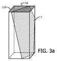
ステップ23、すなわち、設定パラメータの第2のセットを持つ前記トランスデューサ素子から送信された前記超音波信号がプローブ11を移動せずに前記所望の撮像面の超音波エコーデータを取得することができるような前記設定パラメータの第2のセットが存在するかどうかの決定の詳細は、所望の撮像面1がトランスデューサ素子110の二次元アレイと交差する状況及び所望の撮像面1がトランスデューサ素子110の二次元アレイと交差しない状況をそれぞれ示す図3a及び3bと併せて以下に更に説明される。
図3aから理解されることができるように、所望の撮像面1がトランスデューサ素子110の前記二次元アレイと交差する場合、前記結果が肯定である、すなわち、設定パラメータの第2のセットを持つ前記トランスデューサ素子から送信された前記超音波信号がプローブ11を移動せずに前記所望の撮像面の超音波エコーデータを取得することができるような前記設定パラメータの第2のセットが存在すると決定される。 As can be seen from FIG. 3a, if the desired
これに応じて、交線1a上の前記トランスデューサ素子が使用可能にされ、交線1aに隣接した前記トランスデューサ素子は、通常、使用可能にされる。これは、前記関心体積において撮像されることができる面のセットを事前に拘束する。 In response, the transducer elements on the intersection line 1a are enabled and the transducer elements adjacent to the intersection line 1a are normally enabled. This pre-constrains the set of surfaces that can be imaged in the volume of interest.
更に、前記送信信号の対応する詳細な方向は、前記使用可能にされた素子に対するビーム形成パラメータを調整することにより決定される。このようにして、前記使用可能にされた素子からの前記送信信号は、所望の撮像面1に一意的に対応する。 Furthermore, the corresponding detailed direction of the transmitted signal is determined by adjusting beamforming parameters for the enabled elements. In this way, the transmission signal from the enabled element uniquely corresponds to the desired
図3bから理解されることができるように、所望の撮像面1がトランスデューサ素子110の前記二次元アレイと交差しない場合、前記結果は否定である、すなわち、設定パラメータの第2のセットを持つ前記トランスデューサ素子から送信された前記超音波信号がプローブ11を移動せずに前記所望の撮像面の超音波エコーデータを取得することができるような前記設定パラメータの第2のセットが存在しないと決定される。換言すると、トランスデューサ素子110の前記二次元アレイの限定的なスケールによって、トランスデューサ素子110の前記二次元アレイと交差しない所望の撮像面1は、前記第1の位置とは異なる他の位置に前記プローブを移動せずに前記素子の実際の送信信号を用いて撮像されることができない。 As can be seen from FIG. 3b, if the desired
上述の通り、前記結果が否定である場合、すなわち、プローブ11が移動されなければならない場合、処理ユニット12は、プローブ11に対する第2の位置及び第2の角度を導出し、プローブ11が前記対象上の第2の位置に移動され、前記関心体積に対して前記第2の角度に傾けられる場合に、設定パラメータの第3のセットを持つ前記トランスデューサ素子から送信された前記超音波信号が前記所望の撮像面の超音波エコーデータを導出することができるようなトランスデューサ素子110に対する前記設定パラメータの第3のセットを導出するように更に構成される(図2のステップ26)。 As described above, if the result is negative, i.e., if the
当業者により容易に理解されることができるように、通常、前記第2の位置及び前記第2の角度は、両方とも、前記第1の位置及び前記第1の角度とは異なる。しかしながら、場合により、前記第2の角度は、前記第1の角度と同じであってもよい。 As can be readily appreciated by those skilled in the art, typically, the second position and the second angle are both different from the first position and the first angle. However, in some cases, the second angle may be the same as the first angle.
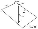
図4a及び図4bは、図3bの場合に、いかにして前記超音波撮像システムのディスプレイ14が本発明の一実施例によって前記プローブを移動するように前記超音波撮像システムのユーザをガイドする命令を出力するのかを示す。 FIGS. 4a and 4b show how to guide the user of the ultrasound imaging system to move the probe according to an embodiment of the present invention in the case of FIG. 3b. Is output.
上述の通り、図3bの場合、所望の撮像面1は、トランスデューサ素子110の前記二次元アレイと交差しない。図4a及び4bに示されるように、トランスデューサ素子110のレイアウトによって、トランスデューサ素子110の前記アレイの中心線の下にある中心基準面2が、決定されることができる。更に、プローブ11の前記位置及び前記第1の角度と所望の撮像面1との間の空間的位置関係によって、プローブ11が前記対象上の前記第2の位置に移動され、前記関心体積に対して前記第2の角度に傾けられる場合に、前記設定パラメータの第3のセットを持つトランスデューサ素子110から送信された前記超音波信号が所望の撮像面1の超音波エコーデータを導出することができるような前記第2の位置、前記第2の角度及び前記設定パラメータの第3のセットである。 As described above, in the case of FIG. 3 b, the desired
例えば、中心基準面2と所望の撮像面1を含む3D空間内の面3との間の空間的位置関係によって、処理ユニット12は、プローブ11が移動されるべきである前記第2の位置を計算することができる。更に、トランスデューサ素子110の前記アレイの前記中心線と所望の撮像面1に対する中心基準面2の交線1bとの間の空間的位置関係によって、処理ユニット12は、プローブ11が前記関心体積に対して傾けられるべきである前記第2の角度を計算することができる。この後に、処理ユニット12は、前記第2の位置及び前記第2の角度において、前記アレイの前記中心線上の前記トランスデューサ素子(及び前記中心線に隣接した一部の素子)が、使用可能にされるべきであり、前記使用可能にされたトランスデューサ素子に対する前記ビーム形成パラメータが、これに応じて決定されることができ、所望の撮像面1が前記使用可能にされた素子からの前記送信信号により直接的に得られることができることを導出しうる。 For example, due to the spatial positional relationship between the central reference plane 2 and the plane 3 in 3D space including the desired
当業者により理解されることができるように、上述の中心基準面2は、一実施例として使用されるだけであり、他の基準面が使用されてもよく、前記第2の位置、前記第2の角度及び前記設定パラメータの第3のセットは、前記基準面の選択によって同様に導出されることができる。 As can be understood by those skilled in the art, the above-described center reference plane 2 is only used as an example, other reference planes may be used, the second position, the first The second angle and the third set of setting parameters can be similarly derived by the selection of the reference plane.
前記第2の位置及び前記第2の角度が導出された場合、超音波撮像システム10のディスプレイ14は、プローブ11を移動するように超音波撮像システム10のユーザをガイドする命令、例えば、プローブ11を前記第2の位置に移動するように前記ユーザにガイドする図4bにおいてI1により示される移動方向、及びプローブ11の前記第2の角度を達成するように前記ユーザをガイドする図4bにおいてI2により示される回転方向を出力する。前記命令は、テキスト、グラフィックス又はこれらの組み合わせのフォーマットにおいて出力されることができる。一部の実施例において、ディスプレイ14は、オーディオを出力することができ、前記命令は、オーディオフォーマットにおいて出力されることができる。When the second position and the second angle are derived, the
更に、当業者により容易に理解されることができるように、複数の手段を列挙する装置請求項において、これらの手段のいくつかは、同一のハードウェアアイテムにより実施されることができる。特定の方策が相互に異なる従属請求項に記載されているという単なる事実は、これらの方策の組み合わせが有利に使用されることができないことを示さない。 Furthermore, in the device claim enumerating several means, several of these means can be embodied by one and the same item of hardware, as can be readily understood by those skilled in the art. The mere fact that certain measures are recited in mutually different dependent claims does not indicate that a combination of these measures cannot be used to advantage.
上述の実施例が、本発明を限定するのではなく説明し、当業者が添付の請求項の範囲から逸脱することなく代替的な実施例を設計することができることに注意すべきである。請求項において、括弧間のいかなる参照符号も、請求項を限定すると解釈されるべきではない。単語「有する」は、請求項及び説明に記載されていない要素又はステップの存在を除外しない。要素に先行する単語"a"又は"an"は、複数のこのような要素の存在を除外しない。いくつかのユニットを列挙するシステム請求項において、これらのユニットのいくつかが、同一のソフトウェア及び/又はハードウェアアイテムにより実施されることができる。第1、第2及び第3等の単語の使用は、順序を示さない。これらの単語は、名称として解釈されるべきである。 It should be noted that the embodiments described above are described rather than limiting the invention, and that alternative embodiments can be designed by those skilled in the art without departing from the scope of the appended claims. In the claims, any reference signs placed between parentheses shall not be construed as limiting the claim. The word “comprising” does not exclude the presence of elements or steps not listed in a claim and in the description. The word “a” or “an” preceding an element does not exclude the presence of a plurality of such elements. In the system claim enumerating several units, several of these units may be embodied by the same software and / or hardware item. The use of words such as first, second and third does not indicate order. These words should be interpreted as names.
Claims (11)
Translated fromJapaneseトランスデューサ素子の二次元アレイを持つ超音波プローブであって、前記プローブが対象上の第1の位置に配置され、関心対象に対して第1の角度に傾けられ、前記プローブの前記トランスデューサ素子が設定パラメータの第1のセットを持つ場合に、前記プローブは、超音波信号を送信し、前記対象の前記関心体積の三次元体積データを取得し、前記関心体積の前記三次元体積データは、前記設定パラメータの第1のセットにより規定された複数のスキャン面の超音波エコーデータを有する、プローブと、
前記三次元体積データによって前記関心体積に対する所望の撮像面を決定し、設定パラメータの第2のセットを持つ前記トランスデューサ素子から送信された前記超音波信号が前記プローブを移動せずに前記所望の撮像面の超音波エコーデータを取得することができるような前記設定パラメータの第2のセットが存在するかどうかの結果を決定する処理ユニットであって、前記処理ユニットは、前記結果が肯定である場合に、前記設定パラメータの第2のセットを導出し、前記結果が否定である場合に、前記プローブが前記対象上の第2の位置に移動され、前記関心体積に対して第2の角度に傾けられる場合に、設定パラメータの第3のセットを持つ前記トランスデューサ素子から送信された前記超音波信号が前記所望の撮像面の超音波エコーデータを導出することができるような前記第2の位置、前記第2の角度及び前記設定パラメータの第3のセットを導出する、処理ユニットと、
前記結果が肯定である場合に、前記導出された設定パラメータの第2のセットによって前記トランスデューサ素子を調整し、前記結果が否定である場合に、前記導出された設定パラメータの第3のセットによって前記トランスデューサ素子を調整するトランスデューサコントローラと、
前記結果が否定である場合に、前記第2の位置に移動され、前記第2の角度に傾けられるように前記プローブを移動するように前記超音波撮像システムのユーザをガイドする命令を出力するディスプレイと、
を有する、超音波撮像システム。In the ultrasound imaging system,
An ultrasonic probe having a two-dimensional array of transducer elements, wherein the probe is positioned at a first position on the object, tilted at a first angle relative to the object of interest, and the transducer elements of the probe are set When having a first set of parameters, the probe transmits an ultrasound signal to obtain three-dimensional volume data of the volume of interest of the object, and the three-dimensional volume data of the volume of interest is the setting A probe having ultrasonic echo data of a plurality of scan planes defined by a first set of parameters;
A desired imaging plane for the volume of interest is determined from the three-dimensional volume data, and the ultrasound signal transmitted from the transducer element having a second set of configuration parameters does not move the probe. A processing unit for determining whether there is a second set of configuration parameters such that ultrasonic echo data of a surface can be obtained, wherein the processing unit is positive if the result is positive Deriving a second set of configuration parameters, and if the result is negative, the probe is moved to a second position on the object and tilted to a second angle with respect to the volume of interest. The ultrasonic signal transmitted from the transducer element having a third set of configuration parameters, the ultrasonic echo of the desired imaging surface The data as may be derived second location, deriving the second angle and the third set of configuration parameters, a processing unit,
If the result is positive, the transducer element is adjusted by the second set of derived configuration parameters, and if the result is negative, the transducer element is adjusted by the third set of derived configuration parameters. A transducer controller for adjusting the transducer elements;
A display that outputs a command to guide a user of the ultrasound imaging system to move to the second position and to move the probe to be tilted to the second angle if the result is negative When,
An ultrasound imaging system.
請求項1に記載の超音波撮像システム。The display displays an image of the desired imaging surface reconstructed from the ultrasound echo data of the desired imaging surface;
The ultrasonic imaging system according to claim 1.
請求項1に記載の超音波撮像システム。The transducer element configuration parameters include which transducer elements are to be enabled and beam forming parameters for the enabled transducer elements.
The ultrasonic imaging system according to claim 1.
請求項1乃至3のいずれか一項に記載の超音波撮像システム。The processing unit automatically determines the desired imaging surface of the volume of interest according to the three-dimensional volume data, a clinical object and a predetermined model;
The ultrasonic imaging system according to any one of claims 1 to 3.
前記ディスプレイが、前記三次元体積データから再構成された複数の画像を表示し、
前記処理ユニットが、前記三次元体積データから再構成された前記複数の画像に基づく前記ユーザの手動選択によって前記関心体積に対する前記所望の撮像面を決定する、
請求項1乃至3のいずれか一項に記載の超音波撮像システム。The ultrasound imaging system has a user interface for receiving input from the user;
The display displays a plurality of images reconstructed from the three-dimensional volume data;
The processing unit determines the desired imaging plane for the volume of interest by manual selection of the user based on the plurality of images reconstructed from the three-dimensional volume data;
The ultrasonic imaging system according to any one of claims 1 to 3.
請求項1に記載の超音波撮像システム。The processing unit is configured to set a set parameter based on the first position of the probe and a spatial positional relationship between the first angle and the desired imaging surface and based on a layout of the transducer elements. A second set of the setting parameters such that the ultrasonic signal transmitted from the transducer element having two sets can acquire ultrasonic echo data of the desired imaging surface without moving the probe; Determine the result of whether or not exists,
The ultrasonic imaging system according to claim 1.
トランスデューサ素子の二次元アレイを持つ超音波プローブを用いて、超音波信号を送信し、対象の関心体積の三次元体積データを取得するステップであって、前記プローブは、前記対象上の第1の位置に配置され、前記関心体積に対して第1の角度に傾けられ、前記プローブの前記トランスデューサ素子は、設定パラメータの第1のセットを持ち、前記関心体積の前記三次元体積データは、前記設定パラメータの第1のセットにより規定された複数のスキャン面の超音波エコーデータを有する、ステップと、
前記三次元体積データによって前記関心体積に対する所望の撮像面を決定するステップと、
設定パラメータの第2のセットを持つ前記トランスデューサ素子から送信された前記超音波信号が前記プローブを移動せずに前記所望の撮像面の超音波エコーデータを取得することができるような前記設定パラメータの第2のセットが存在するかどうかの結果を決定するステップと、
前記結果が肯定である場合に、前記設定パラメータの第2のセットを導出し、前記結果が否定である場合に、前記プローブが前記対象上の第2の位置に移動され、前記関心体積に対して第2の角度に傾けられるときに、設定パラメータの第3のセットを持つ前記トランスデューサ素子から送信された前記超音波信号が前記所望の撮像面の超音波エコーデータを導出することができるような前記第2の位置、前記第2の角度及び前記設定パラメータの第3のセットを導出するステップと、
前記結果が肯定である場合に、前記導出された設定パラメータの第2のセットによって前記トランスデューサ素子を調整し、前記結果が否定である場合に、前記第2の位置に配置され、前記第2の角度に傾けられるように前記プローブを移動するように前記超音波撮像システムのユーザをガイドする命令を出力し、前記導出された設定パラメータの第3のセットによって前記トランスデューサ素子を調整するステップと、
を有する方法。In the ultrasonic imaging method,
Transmitting an ultrasonic signal using an ultrasonic probe having a two-dimensional array of transducer elements to obtain three-dimensional volume data of a volume of interest of the object, the probe comprising: Positioned at a position and tilted at a first angle relative to the volume of interest, the transducer element of the probe has a first set of configuration parameters, and the three-dimensional volume data of the volume of interest is the configuration Having ultrasound echo data of a plurality of scan planes defined by a first set of parameters;
Determining a desired imaging plane for the volume of interest from the three-dimensional volume data;
The setting parameters such that the ultrasonic signal transmitted from the transducer element having a second set of setting parameters can acquire ultrasonic echo data of the desired imaging surface without moving the probe. Determining a result of whether a second set exists;
If the result is positive, a second set of configuration parameters is derived, and if the result is negative, the probe is moved to a second position on the object and relative to the volume of interest. The ultrasonic signal transmitted from the transducer element having a third set of setting parameters can derive ultrasonic echo data of the desired imaging surface when tilted to a second angle. Deriving a third set of the second position, the second angle and the setting parameter;
If the result is positive, the transducer element is adjusted by the second set of derived configuration parameters, and if the result is negative, the transducer element is disposed at the second position, and the second Outputting instructions to guide a user of the ultrasound imaging system to move the probe to be angled and adjusting the transducer elements according to the derived third set of configuration parameters;
Having a method.
を有する、請求項7に記載の方法。Displaying an image of the desired imaging surface reconstructed from the ultrasound echo data of the desired imaging surface;
The method of claim 7, comprising:
請求項7及び8のいずれか一項に記載の方法。The desired imaging plane for the volume of interest is automatically determined by the three-dimensional volume data, a clinical object and a predetermined model;
9. A method according to any one of claims 7 and 8.
請求項7及び8のいずれか一項に記載の方法。The desired imaging plane for the volume of interest is determined by manual selection of the user based on the plurality of images reconstructed from the three-dimensional volume data.
9. A method according to any one of claims 7 and 8.
請求項7に記載の方法。The setting parameter such that the ultrasonic signal transmitted from the transducer element having the second set of setting parameters can acquire ultrasonic echo data of the desired imaging surface without moving the probe. Determining a result of whether a second set of is present based on the first position of the probe and a spatial positional relationship between the first angle and the desired imaging plane, Based on the layout of the transducer elements,
The method of claim 7.
Applications Claiming Priority (5)
| Application Number | Priority Date | Filing Date | Title |
|---|---|---|---|
| CNPCT/CN2014/071553 | 2014-01-27 | ||
| CN2014071553 | 2014-01-27 | ||
| EP14168419.1 | 2014-05-15 | ||
| EP14168419 | 2014-05-15 | ||
| PCT/EP2015/051039WO2015110436A1 (en) | 2014-01-27 | 2015-01-21 | An ultrasound imaging system and an ultrasound imaging method |
Publications (2)
| Publication Number | Publication Date |
|---|---|
| JP2017502789A JP2017502789A (en) | 2017-01-26 |
| JP6097452B2true JP6097452B2 (en) | 2017-03-15 |
Family
ID=52434765
Family Applications (1)
| Application Number | Title | Priority Date | Filing Date |
|---|---|---|---|
| JP2016547084AActiveJP6097452B2 (en) | 2014-01-27 | 2015-01-21 | Ultrasonic imaging system and ultrasonic imaging method |
Country Status (6)
| Country | Link |
|---|---|
| US (1) | US9730675B2 (en) |
| EP (1) | EP3099243B1 (en) |
| JP (1) | JP6097452B2 (en) |
| CN (1) | CN105939670B (en) |
| RU (1) | RU2659021C2 (en) |
| WO (1) | WO2015110436A1 (en) |
Families Citing this family (14)
| Publication number | Priority date | Publication date | Assignee | Title |
|---|---|---|---|---|
| EP3366221A1 (en)* | 2017-02-28 | 2018-08-29 | Koninklijke Philips N.V. | An intelligent ultrasound system |
| US11696745B2 (en)* | 2017-03-16 | 2023-07-11 | Koninklijke Philips N.V. | Optimal scan plane selection for organ viewing |
| US11464490B2 (en) | 2017-11-14 | 2022-10-11 | Verathon Inc. | Real-time feedback and semantic-rich guidance on quality ultrasound image acquisition |
| EP3510932A1 (en)* | 2018-01-11 | 2019-07-17 | Koninklijke Philips N.V. | Ultrasound device for in-situ ultrasound imaging |
| AU2019268319B2 (en)* | 2018-05-15 | 2024-12-05 | New York University | System and method for orientating capture of ultrasound images |
| EP3590436A1 (en) | 2018-07-06 | 2020-01-08 | Koninklijke Philips N.V. | Identifying an optimal image from a number of ultrasound images |
| US20210338208A1 (en)* | 2018-09-07 | 2021-11-04 | Koninklijke Philips N.V. | 3d ultrasound imaging with broadly focused transmit beams at a high frame rate of display |
| EP3639751A1 (en)* | 2018-10-15 | 2020-04-22 | Koninklijke Philips N.V. | Systems and methods for guiding the acquisition of an ultrasound image |
| CN111281424B (en)* | 2018-12-07 | 2024-12-27 | 深圳迈瑞生物医疗电子股份有限公司 | A method for adjusting ultrasonic imaging range and related equipment |
| CN111685793B (en)* | 2019-03-15 | 2025-03-21 | 通用电气公司 | Apparatus and method for image-based control of imaging system parameters |
| CN110433406B (en)* | 2019-09-04 | 2021-05-28 | 珠海医凯电子科技有限公司 | Ultrasonic focusing positioning image optimization method |
| CN113628158A (en)* | 2020-05-08 | 2021-11-09 | 通用电气精准医疗有限责任公司 | Method and system for managing image quality using generative models |
| CN114947932A (en)* | 2021-02-26 | 2022-08-30 | 通用电气精准医疗有限责任公司 | Ultrasonic imaging method and ultrasonic imaging system |
| EP4407558A1 (en)* | 2023-01-26 | 2024-07-31 | Koninklijke Philips N.V. | Obtaining a medical image at a target plane |
Family Cites Families (26)
| Publication number | Priority date | Publication date | Assignee | Title |
|---|---|---|---|---|
| JPH0461853A (en)* | 1990-06-29 | 1992-02-27 | Toshiba Corp | Therapeutic device using applicator |
| US5050610A (en)* | 1990-11-14 | 1991-09-24 | Advanced Technology Laboratories, Inc. | Transesophageal ultrasonic scanhead |
| US5967987A (en)* | 1997-12-18 | 1999-10-19 | Acuson Corporation | Ultrasonic system and method for measurement of fluid flow |
| JP3057228B2 (en)* | 1998-03-31 | 2000-06-26 | 東北大学長 | How to fix the probe position of the scanning probe microscope |
| US6511426B1 (en)* | 1998-06-02 | 2003-01-28 | Acuson Corporation | Medical diagnostic ultrasound system and method for versatile processing |
| US6234968B1 (en)* | 1999-06-15 | 2001-05-22 | Acuson Corporation | 3-D diagnostic medical ultrasound imaging using a 1-D array |
| US6669641B2 (en) | 2000-08-17 | 2003-12-30 | Koninklijke Philips Electronics N.V. | Method of and system for ultrasound imaging |
| US6755788B2 (en) | 2000-08-17 | 2004-06-29 | Koninklijke Philips Electronics N. V. | Image orientation display for a three dimensional ultrasonic imaging system |
| CN101480346A (en)* | 2002-10-10 | 2009-07-15 | 视声公司 | Integrated multi-rail imaging system |
| JP3748848B2 (en)* | 2002-11-11 | 2006-02-22 | ジーイー・メディカル・システムズ・グローバル・テクノロジー・カンパニー・エルエルシー | Ultrasonic diagnostic equipment |
| US20050096538A1 (en)* | 2003-10-29 | 2005-05-05 | Siemens Medical Solutions Usa, Inc. | Image plane stabilization for medical imaging |
| WO2005050252A1 (en) | 2003-11-20 | 2005-06-02 | Koninklijke Philips Electronics, N.V. | Ultrasonic diagnostic imaging with automatic adjustment of beamforming parameters |
| CN101065069B (en) | 2004-10-08 | 2010-05-26 | 皇家飞利浦电子股份有限公司 | Three-dimensional ultrasound scanning of live subvolumes |
| RU2462986C2 (en)* | 2006-11-21 | 2012-10-10 | Конинклейке Филипс Электроникс Н.В. | System, method, machine-readable carrier and their application for visualisation of tissue in anatomical structure |
| JP4865575B2 (en)* | 2007-01-17 | 2012-02-01 | 日立アロカメディカル株式会社 | Ultrasonic diagnostic equipment |
| US8073215B2 (en) | 2007-09-18 | 2011-12-06 | Siemens Medical Solutions Usa, Inc. | Automated detection of planes from three-dimensional echocardiographic data |
| WO2009044316A1 (en) | 2007-10-03 | 2009-04-09 | Koninklijke Philips Electronics N.V. | System and method for real-time multi-slice acquisition and display of medical ultrasound images |
| US20090221908A1 (en) | 2008-03-01 | 2009-09-03 | Neil David Glossop | System and Method for Alignment of Instrumentation in Image-Guided Intervention |
| CN201316280Y (en)* | 2008-12-18 | 2009-09-30 | 刘恩玺 | B ultrasonic puncture locating device |
| US8914245B2 (en) | 2009-03-20 | 2014-12-16 | Andrew David Hopkins | Ultrasound probe with accelerometer |
| US8355554B2 (en) | 2009-04-14 | 2013-01-15 | Sonosite, Inc. | Systems and methods for adaptive volume imaging |
| US20110172526A1 (en)* | 2010-01-12 | 2011-07-14 | Martin Lachaine | Feature Tracking Using Ultrasound |
| JP2013532543A (en) | 2010-07-30 | 2013-08-19 | コーニンクレッカ フィリップス エレクトロニクス エヌ ヴィ | Automatic sweep and export of 3D volume 2D ultrasound images |
| CN102551812B (en) | 2010-12-09 | 2015-11-25 | Ge医疗系统环球技术有限公司 | Ultrasound volume probe navigation and vehicle controL method and apparatus and ultrasonic device |
| US8657750B2 (en)* | 2010-12-20 | 2014-02-25 | General Electric Company | Method and apparatus for motion-compensated ultrasound imaging |
| JP6352001B2 (en)* | 2014-03-05 | 2018-07-04 | キヤノンメディカルシステムズ株式会社 | Medical diagnostic imaging equipment |
- 2015
- 2015-01-21WOPCT/EP2015/051039patent/WO2015110436A1/enactiveApplication Filing
- 2015-01-21USUS15/113,510patent/US9730675B2/ennot_activeExpired - Fee Related
- 2015-01-21JPJP2016547084Apatent/JP6097452B2/enactiveActive
- 2015-01-21EPEP15701728.6Apatent/EP3099243B1/enactiveActive
- 2015-01-21CNCN201580005833.XApatent/CN105939670B/enactiveActive
- 2015-01-21RURU2016134815Apatent/RU2659021C2/enactive
Also Published As
| Publication number | Publication date |
|---|---|
| CN105939670B (en) | 2019-08-06 |
| EP3099243A1 (en) | 2016-12-07 |
| RU2016134815A (en) | 2018-03-07 |
| US9730675B2 (en) | 2017-08-15 |
| JP2017502789A (en) | 2017-01-26 |
| US20170007208A1 (en) | 2017-01-12 |
| CN105939670A (en) | 2016-09-14 |
| RU2659021C2 (en) | 2018-06-26 |
| WO2015110436A1 (en) | 2015-07-30 |
| EP3099243B1 (en) | 2018-04-25 |
Similar Documents
| Publication | Publication Date | Title |
|---|---|---|
| JP6097452B2 (en) | Ultrasonic imaging system and ultrasonic imaging method | |
| US11992369B2 (en) | Intelligent ultrasound system for detecting image artefacts | |
| US11653897B2 (en) | Ultrasonic diagnostic apparatus, scan support method, and medical image processing apparatus | |
| CN110087550B (en) | Ultrasonic image display method, equipment and storage medium | |
| US9891784B2 (en) | Apparatus and method of displaying medical image | |
| EP3463098B1 (en) | Medical ultrasound image processing device | |
| US10456106B2 (en) | Ultrasonic diagnostic apparatus, medical image processing apparatus, and medical image processing method | |
| US20110255762A1 (en) | Method and system for determining a region of interest in ultrasound data | |
| US10368841B2 (en) | Ultrasound diagnostic apparatus | |
| JPWO2006059668A1 (en) | Ultrasonic device, ultrasonic imaging program, and ultrasonic imaging method | |
| KR101100464B1 (en) | An ultrasound system and method for providing a 3D ultrasound image based on a secondary region of interest | |
| JP2016522725A (en) | System and method for 3D acquisition of ultrasound images | |
| JP6382050B2 (en) | Medical image diagnostic apparatus, image processing apparatus, image processing method, and image processing program | |
| CN111629671A (en) | Ultrasonic imaging apparatus and method of controlling ultrasonic imaging apparatus | |
| US20150351725A1 (en) | Ultrasonic diagnosis apparatus and medical image processing apparatus | |
| JP2014161444A (en) | Ultrasound diagnostic device, medical image processor and control program | |
| KR20150131566A (en) | Ultrasound diagnosis apparatus and mehtod thereof | |
| EP3139838A1 (en) | Imaging systems and methods for positioning a 3d ultrasound volume in a desired orientation | |
| JP2014064913A (en) | Ultrasonic diagnostic device, medical image processor and image processing program | |
| KR20130033983A (en) | Ultrasound diagnostic apparatus and method thereof | |
| JP2016022297A (en) | Ultrasonic diagnostic device and control program thereof | |
| CN106604682A (en) | Simultaneous acquisition of harmonic and fundamental images for screening applications | |
| JP6501796B2 (en) | Acquisition Orientation Dependent Features for Model-Based Segmentation of Ultrasound Images | |
| US10521069B2 (en) | Ultrasonic apparatus and method for controlling the same | |
| KR102695456B1 (en) | Ultrasound diagnostic apparatus for displaying shear wave data of the object and method for operating the same |
Legal Events
| Date | Code | Title | Description |
|---|---|---|---|
| A621 | Written request for application examination | Free format text:JAPANESE INTERMEDIATE CODE: A621 Effective date:20160715 | |
| A871 | Explanation of circumstances concerning accelerated examination | Free format text:JAPANESE INTERMEDIATE CODE: A871 Effective date:20160715 | |
| TRDD | Decision of grant or rejection written | ||
| A975 | Report on accelerated examination | Free format text:JAPANESE INTERMEDIATE CODE: A971005 Effective date:20170113 | |
| A01 | Written decision to grant a patent or to grant a registration (utility model) | Free format text:JAPANESE INTERMEDIATE CODE: A01 Effective date:20170126 | |
| A61 | First payment of annual fees (during grant procedure) | Free format text:JAPANESE INTERMEDIATE CODE: A61 Effective date:20170217 | |
| R150 | Certificate of patent or registration of utility model | Ref document number:6097452 Country of ref document:JP Free format text:JAPANESE INTERMEDIATE CODE: R150 | |
| R250 | Receipt of annual fees | Free format text:JAPANESE INTERMEDIATE CODE: R250 | |
| R250 | Receipt of annual fees | Free format text:JAPANESE INTERMEDIATE CODE: R250 | |
| R250 | Receipt of annual fees | Free format text:JAPANESE INTERMEDIATE CODE: R250 | |
| R250 | Receipt of annual fees | Free format text:JAPANESE INTERMEDIATE CODE: R250 | |
| R250 | Receipt of annual fees | Free format text:JAPANESE INTERMEDIATE CODE: R250 |