JP6097265B2 - Airless tire - Google Patents
Airless tireDownload PDFInfo
- Publication number
- JP6097265B2 JP6097265B2JP2014204193AJP2014204193AJP6097265B2JP 6097265 B2JP6097265 B2JP 6097265B2JP 2014204193 AJP2014204193 AJP 2014204193AJP 2014204193 AJP2014204193 AJP 2014204193AJP 6097265 B2JP6097265 B2JP 6097265B2
- Authority
- JP
- Japan
- Prior art keywords
- spoke
- curve
- piece
- tire
- hub
- Prior art date
- Legal status (The legal status is an assumption and is not a legal conclusion. Google has not performed a legal analysis and makes no representation as to the accuracy of the status listed.)
- Active
Links
- 230000002093peripheral effectEffects0.000claimsdescription6
- 239000002861polymer materialSubstances0.000claimsdescription5
- 230000000630rising effectEffects0.000claimsdescription3
- 229920001971elastomerPolymers0.000description8
- 230000003014reinforcing effectEffects0.000description5
- 229920005989resinPolymers0.000description5
- 239000011347resinSubstances0.000description5
- 238000005096rolling processMethods0.000description4
- 229910000831SteelInorganic materials0.000description3
- 238000005452bendingMethods0.000description3
- 238000010586diagramMethods0.000description3
- 239000010959steelSubstances0.000description3
- 229920002803thermoplastic polyurethanePolymers0.000description3
- 229920001187thermosetting polymerPolymers0.000description3
- 230000000694effectsEffects0.000description2
- 238000000034methodMethods0.000description2
- 230000002040relaxant effectEffects0.000description2
- 230000002195synergetic effectEffects0.000description2
- 229910000838Al alloyInorganic materials0.000description1
- 229920000877Melamine resinPolymers0.000description1
- 229910000861Mg alloyInorganic materials0.000description1
- XUIMIQQOPSSXEZ-UHFFFAOYSA-NSiliconChemical compound[Si]XUIMIQQOPSSXEZ-UHFFFAOYSA-N0.000description1
- 239000010426asphaltSubstances0.000description1
- 238000005266castingMethods0.000description1
- 230000006835compressionEffects0.000description1
- 238000007906compressionMethods0.000description1
- 230000008878couplingEffects0.000description1
- 238000010168coupling processMethods0.000description1
- 238000005859coupling reactionMethods0.000description1
- 238000013016dampingMethods0.000description1
- 239000003822epoxy resinSubstances0.000description1
- 238000011156evaluationMethods0.000description1
- 230000001771impaired effectEffects0.000description1
- 238000003780insertionMethods0.000description1
- 230000037431insertionEffects0.000description1
- 239000007769metal materialSubstances0.000description1
- 239000000203mixtureSubstances0.000description1
- 238000000465mouldingMethods0.000description1
- 239000005011phenolic resinSubstances0.000description1
- 229920000647polyepoxidePolymers0.000description1
- 229920001721polyimidePolymers0.000description1
- 239000009719polyimide resinSubstances0.000description1
- 230000001953sensory effectEffects0.000description1
- 229910052710siliconInorganic materials0.000description1
- 239000010703siliconSubstances0.000description1
- 229920005992thermoplastic resinPolymers0.000description1
Images


Classifications
- B—PERFORMING OPERATIONS; TRANSPORTING
- B60—VEHICLES IN GENERAL
- B60C—VEHICLE TYRES; TYRE INFLATION; TYRE CHANGING; CONNECTING VALVES TO INFLATABLE ELASTIC BODIES IN GENERAL; DEVICES OR ARRANGEMENTS RELATED TO TYRES
- B60C7/00—Non-inflatable or solid tyres
- B60C7/10—Non-inflatable or solid tyres characterised by means for increasing resiliency
- B60C7/14—Non-inflatable or solid tyres characterised by means for increasing resiliency using springs
- B60C7/143—Non-inflatable or solid tyres characterised by means for increasing resiliency using springs having a lateral extension disposed in a plane parallel to the wheel axis
- B—PERFORMING OPERATIONS; TRANSPORTING
- B60—VEHICLES IN GENERAL
- B60B—VEHICLE WHEELS; CASTORS; AXLES FOR WHEELS OR CASTORS; INCREASING WHEEL ADHESION
- B60B9/00—Wheels of high resiliency, e.g. with conical interacting pressure-surfaces
- B60B9/02—Wheels of high resiliency, e.g. with conical interacting pressure-surfaces using springs resiliently mounted bicycle rims
- B60B9/04—Wheels of high resiliency, e.g. with conical interacting pressure-surfaces using springs resiliently mounted bicycle rims in leaf form
- B—PERFORMING OPERATIONS; TRANSPORTING
- B60—VEHICLES IN GENERAL
- B60B—VEHICLE WHEELS; CASTORS; AXLES FOR WHEELS OR CASTORS; INCREASING WHEEL ADHESION
- B60B9/00—Wheels of high resiliency, e.g. with conical interacting pressure-surfaces
- B60B9/02—Wheels of high resiliency, e.g. with conical interacting pressure-surfaces using springs resiliently mounted bicycle rims
- B60B9/10—Wheels of high resiliency, e.g. with conical interacting pressure-surfaces using springs resiliently mounted bicycle rims of rubber or the like
- B—PERFORMING OPERATIONS; TRANSPORTING
- B60—VEHICLES IN GENERAL
- B60B—VEHICLE WHEELS; CASTORS; AXLES FOR WHEELS OR CASTORS; INCREASING WHEEL ADHESION
- B60B9/00—Wheels of high resiliency, e.g. with conical interacting pressure-surfaces
- B60B9/26—Wheels of high resiliency, e.g. with conical interacting pressure-surfaces comprising resilient spokes
- B—PERFORMING OPERATIONS; TRANSPORTING
- B60—VEHICLES IN GENERAL
- B60C—VEHICLE TYRES; TYRE INFLATION; TYRE CHANGING; CONNECTING VALVES TO INFLATABLE ELASTIC BODIES IN GENERAL; DEVICES OR ARRANGEMENTS RELATED TO TYRES
- B60C7/00—Non-inflatable or solid tyres
- B60C7/22—Non-inflatable or solid tyres having inlays other than for increasing resiliency, e.g. for armouring
- B—PERFORMING OPERATIONS; TRANSPORTING
- B60—VEHICLES IN GENERAL
- B60C—VEHICLE TYRES; TYRE INFLATION; TYRE CHANGING; CONNECTING VALVES TO INFLATABLE ELASTIC BODIES IN GENERAL; DEVICES OR ARRANGEMENTS RELATED TO TYRES
- B60C7/00—Non-inflatable or solid tyres
- B60C7/10—Non-inflatable or solid tyres characterised by means for increasing resiliency
- B60C7/14—Non-inflatable or solid tyres characterised by means for increasing resiliency using springs
- B60C7/146—Non-inflatable or solid tyres characterised by means for increasing resiliency using springs extending substantially radially, e.g. like spokes
Landscapes
- Engineering & Computer Science (AREA)
- Mechanical Engineering (AREA)
- Tires In General (AREA)
Description
Translated fromJapanese本発明は、乗り心地性能を向上させたエアレスタイヤに関する。 The present invention relates to an airless tire with improved ride comfort performance.
充填内圧によって荷重を支える空気入りタイヤでは、パンクの発生は構造上不可避である。このような問題を解決するため、近年、例えば図6(A)、(B)に略示されるように、トレッドリングaとハブbとの間を、放射状に配列する複数の板状のスポーク片c1からなるスポークcによって連結させた構造のエアレスタイヤが提案されている(例えば、特許文献1参照。)。なお図6(A)にはタイヤの無負荷状態、図6(B)にはタイヤの荷重負荷状態が示される。 In the pneumatic tire that supports the load by the filling internal pressure, the occurrence of puncture is unavoidable due to the structure. In order to solve such problems, in recent years, as schematically shown in FIGS. 6A and 6B, for example, a plurality of plate-like spoke pieces arranged radially between the tread ring a and the hub b are used. An airless tire having a structure connected by a spoke c made of c1 has been proposed (see, for example, Patent Document 1). FIG. 6 (A) shows the tire unloaded state, and FIG. 6 (B) shows the tire loaded state.
前記構造のタイヤは、ハブbや車軸dが、その上部側に位置するスポーク片c1により釣り下げるように保持されており、車軸dに加わる荷重Fは、スポーク片c1の長さ方向の引っ張りによって支持される。 In the tire having the above structure, the hub b and the axle d are held so as to be hung by the spoke piece c1 located on the upper side thereof, and the load F applied to the axle d is caused by pulling in the length direction of the spoke piece c1. Supported.
そのため、凹凸路面を走行する際、路面の凹凸をスポーク片c1の長さ変化によって十分吸収することができず、車軸dに大きな上下動を招くとともに、路面からの衝撃が車軸dに強く伝わるなど乗り心地性能を低下させるという問題がある。なおトレッドリングaの剛性を減じて、トレッドリングa自体の変形により路面の凹凸を吸収させる場合には、タイヤの真円性が悪化し円滑な転動が難しくなるなど転動性能を損ねる結果を招く。 Therefore, when traveling on an uneven road surface, the road surface unevenness cannot be sufficiently absorbed by the change in the length of the spoke piece c1, causing a large vertical movement of the axle d, and an impact from the road surface being strongly transmitted to the axle d. There is a problem of lowering the ride performance. When the rigidity of the tread ring a is reduced and the unevenness of the road surface is absorbed by the deformation of the tread ring a itself, the result is that the roundness of the tire is deteriorated and the rolling performance is impaired such as smooth rolling becomes difficult. Invite.
そこで本発明は、トレッドリングの剛性を高く維持してタイヤの転動性能を確保しながら、乗り心地性能を向上させたエアレスタイヤを提供することを課題としている。 SUMMARY OF THE INVENTION Accordingly, an object of the present invention is to provide an airless tire with improved riding comfort performance while maintaining the tread ring rigidity to ensure tire rolling performance.
本発明は、接地面を有する円筒状のトレッドリング、前記トレッドリングの半径方向内側に配されかつ車軸に固定されるハブ、及び前記トレッドリングとハブとを連結する高分子材料からなるスポークを具えるエアレスタイヤであって、
前記スポークは、周方向に配列する複数のスポーク片を具え、
かつ各前記スポーク片は、タイヤ軸心から放射線状にのびる基準線上に、前記トレッドリングの内周面に連結するトレッド連結部と、前記ハブの外周面に連結するハブ連結部とを有し、しかも前記トレッド連結部とハブ連結部との間に、前記基準線から周方向に逸れて曲線状にのびるスポーク曲線部を含むとともに、
タイヤ軸心から垂直に立ち上がる垂線を0°としたタイヤ軸心廻りの座標系において、
0°におけるスポーク片は、タイヤに正規荷重の60%を負荷した基準荷重負荷状態において前記基準線に沿って測定したスポーク片の半径方向の直線長さLSbが、無負荷状態において前記基準線に沿って測定したスポーク片の半径方向の直線長さLSaの1.05倍以上であり、
しかも0°におけるスポーク片は、基準荷重負荷状態においてスポーク片の曲線に沿って測定した半径方向の曲線長さLLbが、前記直線長さLSbの1.03倍以上であることを特徴としている。The present invention includes a cylindrical tread ring having a ground contact surface, a hub that is arranged radially inside the tread ring and fixed to an axle, and a spoke made of a polymer material that connects the tread ring and the hub. An airless tire,
The spoke includes a plurality of spoke pieces arranged in a circumferential direction,
And each said spoke piece has a tread connection part connected with the inner peripheral surface of the above-mentioned tread ring, and a hub connection part connected with the outer peripheral surface of the above-mentioned hub on a reference line extending radially from the tire axis. Moreover, between the tread connecting portion and the hub connecting portion, including a spoke curve portion extending in a curved shape deviating from the reference line in the circumferential direction,
In the coordinate system around the tire axis with the vertical line rising vertically from the tire axis being 0 °,
The spoke piece at 0 ° has a linear length LSb in the radial direction of the spoke piece measured along the reference line in a reference load load state in which 60% of the normal load is applied to the tire. More than 1.05 times the linear length LSa in the radial direction of the spoke piece measured along
In addition, the spoke piece at 0 ° is characterized in that a radial curve length LLb measured along the curve of the spoke piece in a reference load state is 1.03 times or more of the linear length LSb.
本発明に係る前記エアレスタイヤでは、0°におけるスポーク片は、前記半径方向の曲線長さLLbが、無負荷状態においてスポーク片の曲線に沿って測定した半径方向の曲線長さLLaの1.005倍以下であることが好ましい。 In the airless tire according to the present invention, the spoke piece at 0 ° has a radial curve length LLb of 1.005, which is a radial curve length LLa measured along the curve of the spoke piece in an unloaded state. It is preferable that it is less than 2 times.
本発明に係る前記エアレスタイヤでは、前記スポーク曲線部は、前記基準線から周方向一方側に逸れて曲線状にのびる第1のスポーク曲線部と、基準線から周方向他方側に逸れて曲線状にのびる第2のスポーク曲線部とからなることが好ましい。 In the airless tire according to the present invention, the spoke curved portion includes a first spoke curved portion extending in a curved shape deviating from the reference line toward one side in the circumferential direction, and a curved shape deviating from the reference line toward the other side in the circumferential direction. It is preferable that the second spoke curve portion extends.
本発明に係る前記エアレスタイヤでは、前記スポークは、周方向で隣り合う一方のスポーク片における第1のスポーク曲線部と、他方のスポーク片における第2のスポーク曲線部とを継ぐ継ぎ部を具えることが好ましい。 In the airless tire according to the present invention, the spoke includes a joint portion that connects the first spoke curve portion in one spoke piece adjacent in the circumferential direction and the second spoke curve portion in the other spoke piece. It is preferable.
本発明に係る前記エアレスタイヤでは、前記第1、第2のスポーク曲線部の複素弾性率E*1は、前記継ぎ部の複素弾性率E*2の1.5倍以上、或いは、前記第1、第2のスポーク曲線部の厚さは、前記継ぎ部の厚さの1.5倍以上であることが好ましい。In the airless tire according to the present invention, the complex elastic modulus E *1 of the first and second spoke curve portions is 1.5 times or more than the complex elastic modulus E *2 of the joint portion, or the first The thickness of the second spoke curve portion is preferably 1.5 times or more the thickness of the joint portion.
本発明に係る前記エアレスタイヤでは、前記スポーク片は、前記スポーク曲線部の半径方向外端部と前記トレッド連結部との間を基準線に沿ってのびる外のスポーク基部、及びスポーク曲線部の半径方向内端部と前記ハブ連結部との間を基準線に沿ってのびる内のスポーク基部を含むことができる。In the airless tire according to the present invention, the spoke piece includes an outer spoke base portion extending along a reference line between a radially outer end portion of the spoke curved portion and the tread connecting portion, and a radius of the spoke curved portion. An inner spoke base extending along a reference line between the directional inner end and the hub connecting portion may be included.
本発明に係る前記エアレスタイヤでは、前記スポーク片は、前記スポーク曲線部の半径方向外端部が前記トレッド連結部をなし、かつスポーク曲線部の半径方向内端部が前記ハブ連結部をなすこともできる。 In the airless tire according to the present invention, the spoke piece is configured such that a radially outer end portion of the spoke curved portion forms the tread connecting portion, and a radially inner end portion of the spoke curved portion forms the hub connecting portion. You can also.
本発明は叙上の如く、各スポーク片が、タイヤ軸心から放射状にのびる基準線上に、トレッド連結部とハブ連結部とを有し、しかもトレッド連結部とハブ連結部との間に、基準線から周方向に逸れるスポーク曲線部を含む。 As described above, according to the present invention, each spoke piece has a tread connecting portion and a hub connecting portion on a reference line extending radially from the tire axis, and between the tread connecting portion and the hub connecting portion. Includes spoke curves that deviate circumferentially from the line.
従って、凹凸路面を走行する際、路面の凹凸をスポーク曲線部の曲げ変形によって吸収でき、車軸の上下動を減じるとともに路面からの衝撃を緩和して乗り心地性能を向上させることができる。特に、0°におけるスポーク片において、基準荷重負荷状態におけるスポーク片の直線長さLSbを、無負荷状態におけるスポーク片の直線長さLSaの1.05倍以上としている。これにより、凹凸路面を走行する際の車軸の上下動を減じることができる。また基準荷重負荷状態におけるスポーク片の曲線長さLLbを、基準荷重負荷状態におけるスポーク片の直線長さLSbの1.03倍以上としている。これにより、スポーク片が直線状に伸びきるまでに3%以上の余裕が生まれる。従って、例えば大きな突起物を乗り上げる際の衝撃に対しても、その衝撃を緩和吸収する効果を高く発揮することができ、これらの相乗効果によって、乗り心地性能を向上することができる。 Accordingly, when traveling on an uneven road surface, the road surface unevenness can be absorbed by bending deformation of the spoke curve portion, and the vertical movement of the axle can be reduced and the impact from the road surface can be mitigated to improve the riding comfort performance. In particular, in the spoke piece at 0 °, the linear length LSb of the spoke piece in the reference load state is set to 1.05 times or more of the linear length LSa of the spoke piece in the no-load state. Thereby, the vertical movement of the axle when traveling on an uneven road surface can be reduced. Further, the curve length LLb of the spoke piece in the reference load application state is set to 1.03 times or more of the linear length LSb of the spoke piece in the reference load application state. As a result, a margin of 3% or more is produced before the spoke piece extends straight. Therefore, for example, even when an impact is caused when riding a large protrusion, the effect of relaxing and absorbing the impact can be exerted highly, and the ride comfort performance can be improved by these synergistic effects.
またトレッド連結部及びハブ連結部は、基準線上に位置する。そのため、スポーク曲線部が曲げ変形する際、及び曲げ変形から復帰する際、それに起因する前後力の発生を防止できる。 Further, the tread connecting portion and the hub connecting portion are located on the reference line. For this reason, when the spoke curve portion is bent and deformed, and when the spoke curve portion is restored from the bending deformation, it is possible to prevent the occurrence of the longitudinal force resulting therefrom.
以下、本発明の実施の形態について、詳細に説明する。 Hereinafter, embodiments of the present invention will be described in detail.
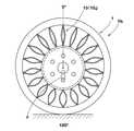
図1、2に示されるように、本実施形態のエアレスタイヤ1は、接地面Sを有する円筒状のトレッドリング2、前記トレッドリング2の半径方向内側に配されかつ車軸Jに固定されるハブ3、及び前記トレッドリング2とハブ3とを連結する高分子材料からなるスポーク4を具える。本例では、前記エアレスタイヤ1が乗用車用タイヤとして形成される場合が示される。 As shown in FIGS. 1 and 2, an
前記トレッドリング2は、空気入りタイヤにおけるトレッド部に相当する部位であり、接地面Sをなすトレッドゴム部2Aと、その半径方向内側に配される補強コード層2Bとを具える。 The
トレッドゴム部2Aとしては、接地に対する摩擦力、耐摩耗性に優れるゴム組成物が好適に採用しうる。又接地面Sには、ウエット性能を付与するために、トレッド溝(図示しない)が種々なパターン形状にて形成される。 As the
補強コード層2Bは、本例では、半径方向外側のアウターブレーカ5と、半径方向内側のインナーブレーカ6とを含むとともに、その間に高弾性ゴムからなる剪断ゴム層7が配される。 In this example, the reinforcing
前記アウターブレーカ5は、例えばスチールコード等の高弾性の補強コードを、タイヤ周方向に対して例えば5〜85°、好ましくは10〜35°の角度で傾斜配列させた複数枚、本例では2枚のアウタープライ5A、5Bから形成される。このアウターブレーカ5は、各補強コードがプライ間相互で交差するように、傾斜の向きを違えて重置される。また前記インナーブレーカ6は、例えばスチールコード等の高弾性の補強コードを、タイヤ周方向に螺旋状に巻回した1枚以上、本例では1枚のインナープライから形成される。 The outer breaker 5 is a plurality of, for example, 2 in this example, in which highly elastic reinforcing cords such as steel cords are inclinedly arranged at an angle of, for example, 5 to 85 °, preferably 10 to 35 ° with respect to the tire circumferential direction. The
前記剪断ゴム層7は、初期歪10%、動歪2%、70℃における複素弾性率E*70が好ましくは70MPa以上、さらに好ましくは90MPa以上の高弾性ゴムから形成される。このような高弾性ゴムの両側を、アウターブレーカ5及びインナーブレーカ6により挟み込んだサンドウィッチ構造とすることにより、トレッドリング2の剛性を大幅に高めることができ、タイヤの転動性能を高く確保することが可能になる。The
前記ハブ3は、タイヤホイールに相当するもので、本例では、車軸Jに固定される円盤状のディスク部3Aと、このディスク部3Aの半径方向外端部に一体に形成される円筒状のスポーク取付け部3Bとを具える。前記ディスク部3Aの中央には、車軸Jの前端部Jaが挿通するハブ孔3A1が形成される。又ハブ孔3A1の周囲には、車軸側に配されるボルト部Jbをナット止めするための複数のボルト挿通孔3A2が設けられる。このようなハブ3としては、タイヤホイールと同様、例えば、スチール、アルミ合金、マグネシウム合金等の金属材料によって形成されるのが好ましい。 The
次に、前記スポーク4は、高分子材料による注型成形により、トレッドリング2及びハブ3と一体成形される。高分子材料としては、熱可塑性樹脂、熱硬化性樹脂が採用しうるが、安全性の観点から、熱硬化性樹脂、例えばエポキシ系樹脂、フェノール系樹脂、ウレタン系樹脂、シリコン系樹脂、ポリイミド系樹脂、メラミン系樹脂などが好適であり、特にウレタン系樹脂は弾性特性に優れるため、より好適に採用しうる。 Next, the
前記スポーク4は、タイヤ周方向に等間隔で配列する複数の板状のスポーク片10を具える。図1に示されるように、各スポーク片10は、そのタイヤ半径方向外端部に、トレッドリング2の内周面と連結するトレッド連結部11を有し、またタイヤ半径方向内端部に、ハブ3の外周面と連結するハブ連結部12を有する。そして、前記トレッド連結部11、及びハブ連結部12は、タイヤ軸心iから放射線状にのびる基準線X上に位置する。 The
また前記スポーク片10は、前記トレッド連結部11とハブ連結部12との間に、基準線Xからタイヤ周方向に逸れて曲線状にのびるスポーク曲線部13を具える。 Further, the
本例のスポーク曲線部13は、基準線Xからタイヤ周方向一方側に逸れて曲線状にのびる第1のスポーク曲線部13Aと、基準線Xからタイヤ周方向他方側に逸れて曲線状にのびる第2のスポーク曲線部13Bとから形成される。第1、第2のスポーク曲線部13A、13Bは、基準線Xを中心とした線対称形状をなす。本例では、第1、第2のスポーク曲線部13A、13Bが略円弧状に湾曲する場合が示されるが、例えば、く字状に屈曲しても良い。 The
また本例では、スポーク片10が、スポーク曲線部13の半径方向外端部とトレッド連結部11との間を基準線Xに沿ってのびる外のスポーク基部14o、及びスポーク曲線部13の半径方向内端部と前記ハブ連結部12との間を基準線Xに沿ってのびる内のスポーク基部14iを含む場合が示される。 Further, in this example, the
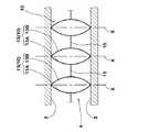
そして、エアレスタイヤ1は、タイヤ軸心iから垂直に立ち上がる垂線を0°としたタイヤ軸心廻りの座標系において、0°におけるスポーク片100は、無負荷状態Ya(図2に示す)、及び基準荷重負荷状態Yb(図3に示す)において下記のように規制される。And, in the coordinate system around the tire axis, the
図4(A)は、無負荷状態Yaのエアレスタイヤ1の0°におけるスポーク片100を、タイヤ半径方向を縦軸方向、タイヤ周方向を横軸方向に展開して示し、図4(B)は、基準荷重負荷状態Ybのエアレスタイヤ1の0°におけるスポーク片100を、タイヤ半径方向を縦軸方向、タイヤ周方向を横軸方向に展開して示している。4A shows the
同図に示されるように、0°におけるスポーク片100は、基準荷重負荷状態Ybにおいて前記基準線Xに沿って測定したスポーク片100の半径方向の直線長さLSbが、無負荷状態Yaにおいて前記基準線Xに沿って測定したスポーク片100の半径方向の直線長さLSaの1.05倍以上である。また0°におけるスポーク片100は、基準荷重負荷状態Ybにおいてスポーク片100の曲線に沿って測定した半径方向の曲線長さLLbが、前記直線長さLSbの1.03倍以上である。As shown in the figure, 0
ここで、前記基準荷重負荷状態Yb(図3に示す)とは、エアレスタイヤ1に正規荷重の60%の荷重Fを負荷した状態を意味し、無負荷状態Ya(図2に示す)とは、エアレスタイヤ1に荷重を負荷しない状態を意味する。また正規荷重とは、前記エアレスタイヤ1のタイヤサイズに置換される空気入りタイヤの正規荷重であって、空気入りタイヤが基づいている規格を含む規格体系において、当該規格がタイヤ毎に定める荷重を意味する。例えば、JATMAであれば最大負荷能力、TRAであれば表 "TIRE LOAD LIMITS AT VARIOUS COLD INFLATION PRESSURES" に記載の最大値、ETRTOであれば "LOAD CAPACITY"を意味する。 Here, the reference load load state Yb (shown in FIG. 3) means a state in which the
前記直線長さLSbが、直線長さLSaの1.05倍以上とすることで、凹凸路面を走行する際の車軸の上下動を減じることができる。また前記曲線長さLLbが直線長さLSbの1.03倍以上とすることで、スポーク片10が直線状に伸びきるまでに3%以上の余裕が生まれる。従って、例えば大きな突起物に乗り上げる際の衝撃を緩和吸収する効果を高く発揮することができる。そしてこれらの相乗効果によって、乗り心地性能を向上することができる。このような観点から、直線長さLSbは直線長さLSaの1.07倍以上がより好ましく、曲線長さLLbは直線長さLSbの1.05倍以上がより好ましい。 When the straight line length LSb is 1.05 times or more of the straight line length LSa, the vertical movement of the axle when traveling on the uneven road surface can be reduced. Further, by setting the curve length LLb to be 1.03 times or more of the straight line length LSb, a margin of 3% or more is produced before the
前記直線長さLSbの上限は特に規制されないが、操縦安定性の観点から、直線長さLSaの1.3倍以下、さらには1.2倍以下が好ましい。また曲線長さLLbの上限も特に規制されないが、操縦安定性の観点から、直線長さLSbの1.2倍以下、さらには1.1倍以下が好ましい。 The upper limit of the linear length LSb is not particularly limited, but is preferably 1.3 times or less, more preferably 1.2 times or less of the linear length LSa, from the viewpoint of steering stability. The upper limit of the curve length LLb is not particularly restricted, but is preferably 1.2 times or less, more preferably 1.1 times or less of the straight line length LSb from the viewpoint of steering stability.
またスポーク片10では、トレッド連結部11とハブ連結部12とが基準線X上に位置するため、スポーク曲線部13が曲げ変形する際、及び曲げ変形から復帰する際、それに起因する前後力の発生を防止でき、操縦安定性の維持を図ることができる。 Moreover, in the
なおスポーク片10のうち、スポーク曲線部13が占める割合が小さすぎると、スポーク曲線部13の変形度合いが大きくなって耐久性に不利を招く。従って、無負荷状態Yaにおいて基準線Xに沿って測定したスポーク曲線部13の半径方向の直線長さLaは、前記スポーク片10全体の前記直線長さLSaの70%以上であるのが好ましい。 In addition, when the ratio which the
本例では、0°におけるスポーク片100は、前記曲線長さLLbが、無負荷状態においてスポーク片100の曲線に沿って測定した半径方向の曲線長さLLaの1.005倍以下である。即ち、基準荷重負荷状態Ybと無負荷状態Yaとで、スポーク片100自体の長さ方向の伸び及び圧縮はほとんど発生していない。これによりスポーク片100の耐久性を高めることができる。In this example, the
なおスポーク曲線部13が、第1、第2のスポーク曲線部13A、13Bを有する場合には、前記曲線長さLLa、LLbは、第1、第2のスポーク曲線部13A、13Bのうちの一方の曲線に沿って測定される。 When the
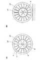
図5に概念的に示すように、スポーク片10では、内外のスポーク基部14i、14oを削除し、スポーク曲線部13のみでスポーク片10を形成することができる。係る場合、スポーク曲線部13の半径方向外端部がトレッド連結部11を形成し、スポーク曲線部13の半径方向内端部がハブ連結部12を形成する。 As conceptually shown in FIG. 5, in the
また同図に示すように、スポーク4は、周方向で隣り合う一方のスポーク片10における第1のスポーク曲線部13Aと、他方のスポーク片10における第2のスポーク曲線部13Bとを継ぐ継ぎ部15を具えることが好ましい。これにより、スポーク4に作用する荷重を、スポーク片10と継ぎ部15とに分散して支持させることができ、耐久性を向上させうる。なお継ぎ部15は、図1、3のスポーク4(スポーク片10が、内外のスポーク基部14i、14oとスポーク曲線部13とで形成される。)にも、形成することができる。 As shown in the figure, the
継ぎ部15を設ける場合、第1、第2のスポーク曲線部13A、13Bの複素弾性率E*1を、前記継ぎ部15の複素弾性率E*2の1.5倍以上とする、或いは、前記第1、第2のスポーク曲線部13A、13Bの厚さを、前記継ぎ部15の厚さの1.5倍以上とすることが、スポーク曲線部13の曲げ変形による好ましい。When the
またスポーク曲線部13としては、例えば第1のスポーク曲線部13Aのみで形成することもでき、またS字状に湾曲させた形状のものも採用しうる。 Moreover, as the
以上、本発明の特に好ましい実施形態について詳述したが、本発明は図示の実施形態に限定されることなく、種々の態様に変形して実施しうる。 As mentioned above, although especially preferable embodiment of this invention was explained in full detail, this invention is not limited to embodiment of illustration, It can deform | transform and implement in a various aspect.
図1、2の基本構造をなすエアレスタイヤ(タイヤサイズ145/70R12に相当するタイヤ)が、表1の仕様に基づいて試作され、実車走行により乗り心地性がテストされた。各タイヤとも、スポーク以外は実質的に同仕様であり、スポークはウレタン樹脂(熱硬化性樹脂)による注型成形法により、トレッドリング及びハブと一体成形された。 An airless tire (a tire corresponding to a tire size 145 / 70R12) having the basic structure shown in FIGS. 1 and 2 was prototyped based on the specifications shown in Table 1, and the ride comfort was tested by running an actual vehicle. Each tire had substantially the same specifications except for the spokes, and the spokes were integrally formed with the tread ring and the hub by a cast molding method using urethane resin (thermosetting resin).
(1)乗り心地性能:
試供タイヤを、車両(超小型EV:商品名COMS)の4輪に装着し、ドライバー1名乗車にて、ドライアスファルト路面の段差路、ベルジャン路(石畳の路面)、ビッツマン路(小石を敷き詰めた路面)等において、ゴツゴツ感、突き上げ、ダンピングに関して官能評価した。結果は、10点法にて表示した。数値が大きいほど良好である。(1) Ride comfort performance:
A sample tire is mounted on four wheels of a vehicle (ultra-compact EV: trade name COMS), and one driver rides a stepped road on a dry asphalt road, a Belgian road (cobblestone road), a Bitzmann road (pebbled with pebbles) On the road surface, etc., sensory evaluations were made with respect to ruggedness, thrust, and damping. The results were displayed by a 10-point method. The larger the value, the better.

表1に示すように、実施例のタイヤは、乗り心地性能に優れているのが確認できる。 As shown in Table 1, it can be confirmed that the tires of the examples are excellent in riding comfort performance.
1 エアレスタイヤ
2 トレッドリング
3 ハブ
4 スポーク
10、100 スポーク片
11 トレッド連結部
12 ハブ連結部
13 スポーク曲線部
13A 第1のスポーク曲線部
13B 第2のスポーク曲線部
14i 内のスポーク基部
14o 外のスポーク基部
15 継ぎ部
i タイヤ軸心
S 接地面
X 基準線
Ya 無負荷状態
Yb 基準荷重負荷状態1
Claims (7)
Translated fromJapanese前記スポークは、周方向に配列する複数のスポーク片を具え、
かつ各前記スポーク片は、タイヤ軸心から放射線状にのびる基準線上に、前記トレッドリングの内周面に連結するトレッド連結部と、前記ハブの外周面に連結するハブ連結部とを有し、しかも前記トレッド連結部とハブ連結部との間に、前記基準線から周方向に逸れて曲線状にのびるスポーク曲線部を含むとともに、
タイヤ軸心から垂直に立ち上がる垂線を0°としたタイヤ軸心廻りの座標系において、
0°におけるスポーク片は、タイヤに正規荷重の60%を負荷した基準荷重負荷状態において前記基準線に沿って測定したスポーク片の半径方向の直線長さLSbが、無負荷状態において前記基準線に沿って測定したスポーク片の半径方向の直線長さLSaの1.05倍以上であり、
しかも0°におけるスポーク片は、基準荷重負荷状態においてスポーク片の曲線に沿って測定した半径方向の曲線長さLLbが、前記直線長さLSbの1.03倍以上であることを特徴とするエアレスタイヤ。An airless tire comprising a cylindrical tread ring having a contact surface, a hub that is arranged radially inside the tread ring and fixed to an axle, and a spoke made of a polymer material that connects the tread ring and the hub. There,
The spoke includes a plurality of spoke pieces arranged in a circumferential direction,
And each said spoke piece has a tread connection part connected with the inner peripheral surface of the above-mentioned tread ring, and a hub connection part connected with the outer peripheral surface of the above-mentioned hub on a reference line extending radially from the tire axis. Moreover, between the tread connecting portion and the hub connecting portion, including a spoke curve portion extending in a curved shape deviating from the reference line in the circumferential direction,
In the coordinate system around the tire axis with the vertical line rising vertically from the tire axis being 0 °,
The spoke piece at 0 ° has a linear length LSb in the radial direction of the spoke piece measured along the reference line in a reference load load state in which 60% of the normal load is applied to the tire. More than 1.05 times the linear length LSa in the radial direction of the spoke piece measured along
In addition, the spoke piece at 0 ° has an airless characteristic in which a radial curve length LLb measured along the curve of the spoke piece in a reference load state is 1.03 times or more of the linear length LSb. tire.
The complex elastic modulus E *1 of the first and second spoke curve portions is 1.5 times or more than the complex elastic modulus E *2 of the joint portion, or the thickness of the first and second spoke curve portions. The airless tire according to claim 4, wherein the length is 1.5 times or more the thickness of the joint portion.
Priority Applications (3)
| Application Number | Priority Date | Filing Date | Title |
|---|---|---|---|
| JP2014204193AJP6097265B2 (en) | 2014-10-02 | 2014-10-02 | Airless tire |
| EP15187913.7AEP3009273B1 (en) | 2014-10-02 | 2015-10-01 | Airless tire |
| US14/873,384US10252572B2 (en) | 2014-10-02 | 2015-10-02 | Airless tire |
Applications Claiming Priority (1)
| Application Number | Priority Date | Filing Date | Title |
|---|---|---|---|
| JP2014204193AJP6097265B2 (en) | 2014-10-02 | 2014-10-02 | Airless tire |
Publications (2)
| Publication Number | Publication Date |
|---|---|
| JP2016074249A JP2016074249A (en) | 2016-05-12 |
| JP6097265B2true JP6097265B2 (en) | 2017-03-15 |
Family
ID=54251450
Family Applications (1)
| Application Number | Title | Priority Date | Filing Date |
|---|---|---|---|
| JP2014204193AActiveJP6097265B2 (en) | 2014-10-02 | 2014-10-02 | Airless tire |
Country Status (3)
| Country | Link |
|---|---|
| US (1) | US10252572B2 (en) |
| EP (1) | EP3009273B1 (en) |
| JP (1) | JP6097265B2 (en) |
Families Citing this family (26)
| Publication number | Priority date | Publication date | Assignee | Title |
|---|---|---|---|---|
| CA2915483C (en) | 2013-06-15 | 2021-11-16 | Ronald Thompson | Annular ring and non-pneumatic tire |
| EP3253591B1 (en) | 2015-02-04 | 2021-06-30 | Camso Inc. | Non-pneumatic tire and other annular devices |
| WO2017106750A1 (en) | 2015-12-16 | 2017-06-22 | Thompson Ronald H | Track system for traction of a vehicle |
| CA173202S (en)* | 2016-09-02 | 2018-02-16 | Razor Usa Llc | Airless tire |
| CN106114066A (en)* | 2016-09-06 | 2016-11-16 | 深圳市金特安科技有限公司 | Open architecture tire |
| JP1576394S (en)* | 2016-10-28 | 2017-05-15 | ||
| USD832770S1 (en)* | 2016-10-28 | 2018-11-06 | Bridgestone Corporation | Non-pneumatic tire |
| JP1579281S (en)* | 2016-10-28 | 2017-06-19 | ||
| US10384409B2 (en)* | 2016-11-15 | 2019-08-20 | The Goodyear Tire & Rubber Company | Method of manufacturing a non-pneumatic support structure |
| CA3067053A1 (en) | 2017-06-15 | 2018-12-20 | Camso Inc. | Wheel comprising a non-pneumatic tire |
| US11491819B2 (en)* | 2017-11-02 | 2022-11-08 | The Goodyear Tire & Rubber Company | Non-pneumatic support structure |
| US11584163B2 (en)* | 2017-11-02 | 2023-02-21 | The Goodyear Tire & Rubber Company | Non-pneumatic support structure |
| CN109927486B (en)* | 2017-12-18 | 2024-05-17 | 岳阳山益科技有限公司 | A bonded solid tire with shock-absorbing function |
| EP3807107B1 (en)* | 2018-06-14 | 2023-06-28 | Bridgestone Americas Tire Operations, LLC | Pre-strained non-pneumatic tire and method of making same |
| US11806959B2 (en)* | 2019-04-12 | 2023-11-07 | Ford Global Technologies, Llc | Tools for manufacturing non-pneumatic tires |
| CN110091669A (en)* | 2019-05-21 | 2019-08-06 | 浙江竤屹科技有限公司 | A kind of good air-free tyre of absorbing shock performance |
| KR102103781B1 (en)* | 2019-06-10 | 2020-04-23 | 김민수 | Airless wheel |
| US10889148B1 (en) | 2019-07-06 | 2021-01-12 | John McGill | Airless tire |
| CA3150286A1 (en)* | 2019-08-09 | 2021-02-18 | Berkshire Grey, Inc. | Systems and methods for providing wheels having variable spring rates |
| US20210061012A1 (en)* | 2019-08-29 | 2021-03-04 | The Goodyear Tire & Rubber Company | Non-pneumatic looper tire |
| JP7452961B2 (en)* | 2019-09-06 | 2024-03-19 | Toyo Tire株式会社 | non pneumatic tires |
| EP4139135A4 (en) | 2020-04-24 | 2024-06-12 | Milwaukee Electric Tool Corporation | Wheel with deformable interfacing spokes |
| CN112706563B (en)* | 2021-01-18 | 2022-05-17 | 青岛科技大学 | Non-pneumatic elastomer tire with bionic tooth structure |
| US12263698B2 (en)* | 2021-08-17 | 2025-04-01 | Briggs & Riley Travelware Llc | Shock absorbing luggage wheel |
| KR20230160135A (en)* | 2022-05-16 | 2023-11-23 | 현대자동차주식회사 | Wheel and mobility including the same |
| EP4331867B1 (en)* | 2022-08-29 | 2025-03-12 | Venturi Lab SA | Deformable wheel with non-pneumatic load support for conditions on the moon and mars |
Family Cites Families (16)
| Publication number | Priority date | Publication date | Assignee | Title |
|---|---|---|---|---|
| DE341256C (en)* | ||||
| US1348834A (en)* | 1913-11-03 | 1920-08-03 | Ideal Wheel Company | Spring-wheel |
| GB156482A (en)* | 1918-10-17 | 1921-07-14 | David Dewey Bohannon | Resilient wheel |
| US7418988B2 (en)* | 1999-12-10 | 2008-09-02 | Michelin Recherche Et Technique S.A. | Non-pneumatic tire |
| US7650919B2 (en) | 1999-12-10 | 2010-01-26 | Michelin Recherche of Technique S.A. | Non-pneumatic tire having web spokes |
| US7143797B2 (en)* | 2005-01-04 | 2006-12-05 | Frederick F. Vannan | Airless tire |
| JP4857706B2 (en)* | 2005-10-19 | 2012-01-18 | 横浜ゴム株式会社 | Non-pneumatic tire |
| BRPI0711471B1 (en)* | 2006-09-20 | 2020-02-04 | Compagnie Generale Des Etablissements Michelin | deformable non-pneumatic structure |
| JP4506853B2 (en)* | 2008-02-25 | 2010-07-21 | 横浜ゴム株式会社 | Non-pneumatic tire |
| JP4674253B2 (en)* | 2008-11-28 | 2011-04-20 | 東洋ゴム工業株式会社 | Non-pneumatic tire |
| US8944125B2 (en)* | 2009-07-20 | 2015-02-03 | Polaris Industries Inc. | Tension-based non-pneumatic tire |
| JP2011126071A (en)* | 2009-12-16 | 2011-06-30 | Riso Kagaku Corp | Stencil original paper |
| US8991455B2 (en)* | 2011-08-30 | 2015-03-31 | Compagnie Generale Des Etablissements Michelin | Molded article and venting assembly for a rotating mold |
| KR101378436B1 (en)* | 2012-06-27 | 2014-03-27 | 한국타이어 주식회사 | Airless tire |
| JP6043582B2 (en)* | 2012-10-22 | 2016-12-14 | 株式会社ブリヂストン | Non pneumatic tire |
| JP6081776B2 (en)* | 2012-11-12 | 2017-02-15 | 東洋ゴム工業株式会社 | Non-pneumatic tire |
- 2014
- 2014-10-02JPJP2014204193Apatent/JP6097265B2/enactiveActive
- 2015
- 2015-10-01EPEP15187913.7Apatent/EP3009273B1/enactiveActive
- 2015-10-02USUS14/873,384patent/US10252572B2/enactiveActive
Also Published As
| Publication number | Publication date |
|---|---|
| EP3009273B1 (en) | 2018-02-21 |
| JP2016074249A (en) | 2016-05-12 |
| US20160096400A1 (en) | 2016-04-07 |
| US10252572B2 (en) | 2019-04-09 |
| EP3009273A1 (en) | 2016-04-20 |
Similar Documents
| Publication | Publication Date | Title |
|---|---|---|
| JP6097265B2 (en) | Airless tire | |
| JP6383294B2 (en) | Airless tire | |
| JP6159138B2 (en) | Airless tire | |
| KR102581110B1 (en) | Airless tire | |
| JP6690103B2 (en) | Non-pneumatic tire | |
| EP3159187B1 (en) | Airless tire | |
| KR101362120B1 (en) | Airless tire | |
| JP6317633B2 (en) | Airless tire | |
| JP5541348B2 (en) | Non-pneumatic tire | |
| JP4946011B2 (en) | Non-pneumatic tire | |
| JP6076704B2 (en) | Non-pneumatic tire | |
| JP5441147B2 (en) | Non-pneumatic tire | |
| JP6215082B2 (en) | Non-pneumatic tire | |
| JP6555405B2 (en) | Airless tire | |
| JP4132123B2 (en) | Non-pneumatic tire | |
| JP5543846B2 (en) | Non-pneumatic tire | |
| JP6697060B2 (en) | Bead reinforcement device for pneumatic tires | |
| JP2013018427A (en) | Non-pneumatic tire | |
| JP5961671B2 (en) | Pneumatic solid tire | |
| KR20170009508A (en) | Non-pneumatic tire | |
| KR20230156227A (en) | A nonpneumatic tire having spokes with cross members | |
| JP2011240885A (en) | Pneumatic solid tire | |
| JPH01317812A (en) | Radial tire | |
| JP2010254027A (en) | Pneumatic tire |
Legal Events
| Date | Code | Title | Description |
|---|---|---|---|
| A621 | Written request for application examination | Free format text:JAPANESE INTERMEDIATE CODE: A621 Effective date:20160422 | |
| TRDD | Decision of grant or rejection written | ||
| A01 | Written decision to grant a patent or to grant a registration (utility model) | Free format text:JAPANESE INTERMEDIATE CODE: A01 Effective date:20170207 | |
| A61 | First payment of annual fees (during grant procedure) | Free format text:JAPANESE INTERMEDIATE CODE: A61 Effective date:20170217 | |
| R150 | Certificate of patent or registration of utility model | Ref document number:6097265 Country of ref document:JP Free format text:JAPANESE INTERMEDIATE CODE: R150 | |
| R250 | Receipt of annual fees | Free format text:JAPANESE INTERMEDIATE CODE: R250 | |
| R250 | Receipt of annual fees | Free format text:JAPANESE INTERMEDIATE CODE: R250 | |
| R250 | Receipt of annual fees | Free format text:JAPANESE INTERMEDIATE CODE: R250 | |
| R250 | Receipt of annual fees | Free format text:JAPANESE INTERMEDIATE CODE: R250 | |
| R250 | Receipt of annual fees | Free format text:JAPANESE INTERMEDIATE CODE: R250 | |
| R250 | Receipt of annual fees | Free format text:JAPANESE INTERMEDIATE CODE: R250 |