JP6095420B2 - Information input device - Google Patents
Information input deviceDownload PDFInfo
- Publication number
- JP6095420B2 JP6095420B2JP2013045203AJP2013045203AJP6095420B2JP 6095420 B2JP6095420 B2JP 6095420B2JP 2013045203 AJP2013045203 AJP 2013045203AJP 2013045203 AJP2013045203 AJP 2013045203AJP 6095420 B2JP6095420 B2JP 6095420B2
- Authority
- JP
- Japan
- Prior art keywords
- finger
- contact
- operator
- operation surface
- sensor
- Prior art date
- Legal status (The legal status is an assumption and is not a legal conclusion. Google has not performed a legal analysis and makes no representation as to the accuracy of the status listed.)
- Expired - Fee Related
Links
- 230000005540biological transmissionEffects0.000claimsdescription39
- 238000001514detection methodMethods0.000claimsdescription31
- 238000013459approachMethods0.000claimsdescription20
- 238000000034methodMethods0.000claimsdescription14
- 230000035945sensitivityEffects0.000claimsdescription11
- 238000005259measurementMethods0.000description26
- 238000004891communicationMethods0.000description25
- 230000007423decreaseEffects0.000description6
- 239000000758substrateSubstances0.000description5
- 238000010586diagramMethods0.000description4
- 230000010355oscillationEffects0.000description3
- 238000012545processingMethods0.000description2
- 238000012790confirmationMethods0.000description1
- 230000008878couplingEffects0.000description1
- 238000010168coupling processMethods0.000description1
- 238000005859coupling reactionMethods0.000description1
- 230000005684electric fieldEffects0.000description1
- 238000005516engineering processMethods0.000description1
- 239000011521glassSubstances0.000description1
- 239000012212insulatorSubstances0.000description1
- 239000004973liquid crystal related substanceSubstances0.000description1
- 239000002699waste materialSubstances0.000description1
Images


Landscapes
- Position Input By Displaying (AREA)
- User Interface Of Digital Computer (AREA)
Description
Translated fromJapanese本発明は、接触するとクリック感を得られる情報入力装置に関する。 The present invention relates to an information input device capable of obtaining a click feeling when touched.
例えば、特許文献1には、操作者のタッチ操作によりクリック感(操作感)を得られる情報入力装置が記載されている。この情報入力装置のタッチセンサ(操作面)は、例えば、静電容量方式で構成され、操作者の指が操作面に接触すると、指が触れる部分の静電容量値が減少する。この静電容量の変化に基づいて、この装置は、操作面に対する接触の位置を検出すると共に、振動動作をすることにより、操作者は、操作確認のクリック感を得られる。 For example,
しかし、上述の装置では、指が操作面から離れようとした際のクリック感が得られなかった。すなわち、上述の装置では、指が操作面から離れたことを検知した後に振動動作をしても、指は操作面から離れているため、操作者はクリック感が得られなかった。 However, in the above-described apparatus, a click feeling when a finger is about to leave the operation surface cannot be obtained. That is, in the above-described apparatus, even if the vibration operation is performed after detecting that the finger is separated from the operation surface, the operator cannot obtain a click feeling because the finger is separated from the operation surface.
そこで本発明は、従来技術が抱える上記課題を解決し得る情報入力装置を提供しようとするものである。 Therefore, the present invention intends to provide an information input device that can solve the above-described problems of the prior art.
上記の課題を解決するため、
操作面への近接物体の接近を検出する近接センサと、
前記近接センサより検出感度が低く前記操作面への近接物体の面接触を検出する接触センサと、
前記操作面を振動させる振動発生部を備え、
前記近接センサが近接物体の接近を検出すると、第1の所定の処理が行われ、
前記接触センサが近接物体の面接触を検出すると、前記振動発生部が第1期間動作し、
前記操作面から近接物体が離れようとする状態を前記接触センサが検出すると、前記振動発生部が第2期間動作して、
前記接触センサは、前記近接センサの外周にループ状に形成されていることを特徴とする。To solve the above problem,
A proximity sensor that detects the proximity of a proximity object to the operation surface;
A contact sensor that has lower detection sensitivity than the proximity sensor and detects surface contact of a proximity object to the operation surface;
Comprising a vibration generating section for vibrating the operation surface;
When the proximity sensor detects the approach of a proximity object, a first predetermined process is performed,
When the contact sensor detects surface contact of a proximity object, the vibration generating unit operates for a first period,
When the contact sensor detects a state in which a proximity object is about to leave the operation surface, the vibration generating unit operatesfor a second period,
The contact sensor is formed in a loop shape on the outer periphery of the proximity sensor .
本発明の情報入力装置は、更なる好ましい特徴として、
「前記接触センサは、近接物体が離れようとする状態を近接物体との接触面積に応じた信号の大きさにより検出すること」、
「前記操作面に形成された最小検出領域に、少なくとも1つの前記近接センサと、少なくとも1つの前記接触センサを有すること」、
「前記操作面から近接物体が離れようとする状態を前記接触センサが検出すると、第2の所定の処理が行われること」、
「前記第1期間内に、前記操作面から近接物体が離れようとする状態を前記接触センサが検出すると、前記振動発生部は、前記第1期間の途中から連続して前記第2期間動作すること」、
「前記第1期間の振動発生部の動作は、前記第2期間の振動発生部の動作と異なること」、
「前記接触センサは、人体を伝送路として用いること」、
「前記接触センサは複数の送信電極を有し、
前記送信電極に信号を出力する1つの発振部を有し、
前記発振部の出力が前記送信電極にそれぞれ接続されていること」、
「前記近接センサは、静電容量センサであること」、
を含むものである。
The information input device of the present invention has a further preferable feature as follows:
“The contact sensor detects a state in which the proximity object is about to leave based on the magnitude of a signal corresponding to the contact area with the proximity object.”
“Having at least one proximity sensor and at least one contact sensor in the minimum detection region formed on the operation surface”;
“When the contact sensor detects a state in which a proximity object is about to leave the operation surface, a second predetermined process is performed.”
“When the contact sensor detects a state in which the proximity object is about to move away from the operation surface within the first period, the vibration generating unit continuously operates from the middle of the first period for the second period. about",
"The operation of the vibration generating unit in the first period is different from the operation of the vibration generating unit in the second period",
"The contact sensor uses a human body as a transmission path",
"The contact sensor has a plurality of transmitting electrodes,
One oscillating unit for outputting a signal to the transmission electrode;
The output of the oscillating unit is connected to the transmission electrode, respectively. "
"The proximity sensor is a capacitance sensor",
Is included.
本発明の情報入力装置は、近接物体(例えば操作者の指)が操作面に面接触した時と離れようとした時の両方でクリック感を得られ、操作確認できる。 The information input device according to the present invention can obtain a click feeling both when a proximity object (for example, an operator's finger) comes into surface contact with the operation surface and when it is about to leave, and can confirm the operation.
以下、図面に基づいて本発明の実施の形態を例示的に説明する。 Hereinafter, embodiments of the present invention will be exemplarily described based on the drawings.
(第1の実施形態例)
本発明の第1の実施形態例を図1ないし図4を用いて説明する。
本例の情報入力装置1は、例えば、携帯電話やゲーム機などの携帯端末や、銀行に設置されるATM、駅に設置される券売機など、近接物体(例えば操作者の指等)の操作面2への操作に基づいて入力操作を行うものであれば、任意の装置に適用することができる。(First embodiment)
A first embodiment of the present invention will be described with reference to FIGS.
The
本例の情報入力装置1は、図1に示すように、近接センサ11と、接触センサ12と、振動発生部30と、マイクロコンピュータ40を有する。 As shown in FIG. 1, the
本例の近接センサ11と接触センサ12は、操作者の指の近接と接触を検出するものであり、ガラスやプラスチックなどの透明な絶縁体からなる操作面2の下側に配置されている。
この近接センサ11と接触センサ12はそれぞれ導電パターンであり透過型の多層基板に形成されている。この多層基板の上層には接触センサ12が形成され、この多層基板の下層には近接センサ11が形成され、多層基板の上面が操作面2の下面に接して配されている。The
Each of the
そして、多層基板の下側に、図示しない表示部の前面が配置され、表示部に表示したキーやボタン等のオブジェクトを操作者が操作できるようになっている。この表示部は、例えば、液晶表示パネルや有機EL表示パネル等を用いて構成される。 A front surface of a display unit (not shown) is arranged below the multilayer substrate so that an operator can operate objects such as keys and buttons displayed on the display unit. This display unit is configured using, for example, a liquid crystal display panel or an organic EL display panel.
そして、本例では、操作面2に形成された最小検出領域3に、1つの近接センサ11と、1つの接触センサ12が設けられている。この最小検出領域3は、操作者が1本の指で操作できるように、平面視で一辺が1mm以上26mm以下の正方形(縦と横が同じXmm)として形成されている。この最小検出領域3の一辺が26mmを超えると、1本の指の大きさを超えて検出しない非検出領域が増えて無駄が生じてしまい、1mm未満であると目視しにくくなり操作性が低下してしまう。この最小検出領域3の一辺は、1mm以上20mm以下が好ましく、1mm以上10mm以下が特に好ましい。
なお、本明細書において、操作面とは、操作者の指が接近と接触をする最小検出領域3を指す。In this example, one
In this specification, the operation surface refers to the
近接センサ11は、操作面2への操作者の指の接近を検出するものである。本例の近接センサ11は、静電容量センサにより構成されており、操作面2の表面から所定の距離離れた範囲(例えば操作面2上面から5mm以下)を検出範囲としている。 The
この近接センサ11は、静電容量用の送信電極11Aと受信電極11Bを有する。送信電極11Aと受信電極11Bは、図1に示すように、それぞれ正方形のループ状で離れて配されている。この送信電極11Aは、受信電極11Bの外周に配されており、入れ子状になっている。なお、本明細書において、ループ状とは、始端と終端を有するC字状やコ形状の導電パターンも含むものである。 The
この送信電極11Aには、第1の発振部21から高周波信号S11が入力される。この信号S11は、例えば、図2に示すように、振幅V11=数Vp−p、周波数F1(=1/T1)=145kHzのパルス波形となっており、図1の測定点Aの電圧波形である。本例の場合、周波数F1は、1kHz〜500kHzが好ましい。 A high-frequency signal S11 is input from the
受信電極11Bは、送信電極11Aと静電結合されており、静電容量の変化を検出する。この受信電極11Bは、第1の受信部22の入力側に接続されており、第1の受信部22は、不図示の、前段の第1整流回路と、後段の第1コンパレータを備える整流回路を有する。第1整流回路は、受信電極11Bに現れる電圧波形を直流に変換し、第1最大電圧値を出力する。第1コンパレータは、該第1最大電圧値と、操作者の指の接近を検出する第1の閾値L1とを比較した結果を出力する。第1の閾値L1は、操作者の指が操作面2に接近していない状態である図2の信号S12の第1最大電圧値V12より低く、操作者の指が操作面2に接近した状態である図2の信号S13の第1最大電圧値V13より高く設定されている。
そして、第1コンパレータは、例えば、第1最大電圧値が第1の閾値L1より低いとハイレベルを出力し、第1最大電圧値が第1の閾値L1より高いとローレベルを出力する。The
For example, the first comparator outputs a high level when the first maximum voltage value is lower than the first threshold L1, and outputs a low level when the first maximum voltage value is higher than the first threshold L1.
接触センサ12は、近接センサ11より検出感度が低く構成されており、操作面2への指の面接触を検出するものである。すなわち、接触センサ12は、操作者の指が操作面2に接近したことを検出した後、さらに操作者の指が操作面2に面接触したことを検出するものである。
なお、本明細書において、面接触とは、指先が操作面2を若干押圧したときの指先と操作面との接触をさし、点接触とは、指先が操作面2に触れる際の指先と操作面との僅かな接触をさす。The
In this specification, surface contact refers to contact between the fingertip and the operation surface when the fingertip presses the
本例の接触センサ12は、図1に示すように、近接センサ11の外周に配されている。この接触センサ12は、人体通信用の送信電極12Aと受信電極12Bを有する。ここで、人体通信とは、人体を通信路として利用し近距離のデータ通信を行う通信技術である。本例は、電界方式を用い、操作者の指が操作面2に触れた際の信号の振幅値の変化を見るものである。本例の場合、その信号にデータを載せてもよいが、データを載せない状態で説明する。 The
人体通信用の送信電極12Aと受信電極12Bは、それぞれ正方形のループ状に形成され、送信電極12Aは、受信電極12Bの内周に形成され入れ子状になっている。そして、操作者の指が操作面2に面接触すると、接触センサは操作者の指の接触を検出する。 The
この送信電極12Aには、第2の発振部25から信号S21が入力される。この信号S21は、例えば、図3の信号S21に示すように、振幅V21=数Vp−p、周波数F2(=1/T2)=20MHzのパルス波形となっており、図1の測定点Cの電圧波形である。人体通信用の周波数F2は、1MHz〜50MHzが好ましい。 A signal S21 is input from the
受信電極12Bは、第2の受信部26の入力側に接続されており、第2の受信部26は、不図示の、前段の第2整流回路と、後段の第2コンパレータを備える整流回路を有する。この第2整流回路は、受信電極12Bに現れる電圧波形を直流に変換し、第2最大電圧値を出力する。第2コンパレータは、該第2最大電圧値と操作者の指が操作面2に面接触したことを検出する第2の閾値L2を比較した結果を出力する。この第2の閾値L2は、操作者の指が操作面2に点接触した状態の図3の信号S23の第2最大電圧値V23より高く、操作者の指が操作面2に面接触した状態の図3の信号S24の最大電圧値V24より低く設定されている。
そして、第2コンパレータは、例えば、第2最大電圧値が第2の閾値L2より高いとハイレベルを出力し、第2最大電圧値が第2の閾値L2より低いとローレベルを出力する。The receiving
For example, the second comparator outputs a high level when the second maximum voltage value is higher than the second threshold L2, and outputs a low level when the second maximum voltage value is lower than the second threshold L2.
振動発生部30は、操作者の操作面2への操作に基づいて操作面2を振動させるものである。具体的には、操作者の指が操作面2に面接触した状態が検出されると振動発生部30が動作し、同様に、操作者の指が操作面2から離れようとする状態が検出されると、振動発生部30が動作する。これによって操作者は、クリック感を得られる。
本例の振動発生部30は、操作面2を振動させるものであれば、様々なものを用いることができ、例えば、振動モータや圧電振動子を用いる。The
As the
マイクロコンピュータ40は、操作面2への操作者の指の接近と面接触の有無を検出し、振動発生部30を動作させるものである。このマイクロコンピュータ40には、第1コンパレータと第2コンパレータの出力がそれぞれ入力される。 The
ここで、本例の作用を説明すると、操作者の指が操作面2に接近すると、操作者の指により近接センサ11の電極間の電気力線が遮断されて電気力線の数が減少し、近接センサ11の受信信号の振幅値が低下する。そして、この振幅値が操作者の指の接近を検出する第1の閾値L1より下がることで、操作者の指が操作面2に接近したことが検出される。
また、操作者の指が操作面2に面接触すると、操作者の指が人体通信用の伝送路となるため、接触センサ12の受信信号の振幅値が増加し、この振幅値が操作者の指が操作面2に面接触したことを検出する第2の閾値L2を超えることで、操作者の指が操作面2に面接触したことが検出され、また、該振幅値が、第2の閾値L2を超えた状態から下がると、操作者の指が操作面2から離れようとすることが検出されるものである。Here, the operation of this example will be described. When the operator's finger approaches the
Further, when the operator's finger comes into surface contact with the
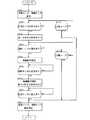
次に、本例の情報入力装置1の動作を、図4のフローチャートを用いて説明する。 Next, operation | movement of the
始めに、マイクロコンピュータ40は、近接センサ11と接触センサ12を動作させるように、第1の発振部21と第2の発振部25にそれぞれに動作制御信号を出力する。そして、第1の発振部21と第2の発振部25は同時に駆動する(S101)。 First, the
まず、操作者の指が操作面2に近接していない状態を説明する。 First, a state where the operator's finger is not close to the
測定点Bにおける電圧波形は、例えば、図2の信号S12のようになる。測定点Dにおける電圧波形は、例えば、図3の信号S22のようになる。 The voltage waveform at the measurement point B is, for example, the signal S12 in FIG. A voltage waveform at the measurement point D is, for example, a signal S22 in FIG.
この場合、第1コンパレータと第2コンパレータの出力は共にローレベルとなり、マイクロコンピュータ40は、操作者の指が操作面2に接近していないと共に、操作者の指が操作面2に面接触していない状態であることを検出する。
なお、所定期間経って、接近していない状態が検出されると、マイクロコンピュータ40は、停止制御信号を出力し、近接センサ11と接触センサ12は動作を停止する。In this case, both the outputs of the first comparator and the second comparator are at a low level, and the
In addition, when the state which is not approaching after a predetermined period is detected, the
次に、操作者の指が操作面2に接近した状態を説明する。この接近した状態は、例えば、操作者の指が静電容量用の送信電極11Aや受信電極11Bの一方に近接された状態や両方に跨って近接された状態などでもよい。 Next, a state in which the operator's finger approaches the
測定点Bにおける電圧波形は、例えば、図2の信号S13のようになる。具体的には、操作者の指が操作面2に接近すると、操作者の指により電気力線が遮断されて2つの電極間の電気力線の数が減少して、受信電極11Bにおける電圧波形の振幅値が低下する。
つまり、操作者の指が操作面2に接近すると、送信電極11Aと受信電極間11Bの静電容量が減少して、図2の信号S13のように、第1最大電圧値V13が操作者の指の接近を検出する第1の閾値L1より下がる。The voltage waveform at the measurement point B is, for example, a signal S13 in FIG. Specifically, when the operator's finger approaches the
That is, when the operator's finger approaches the
測定点Dにおける電圧波形は、図3の信号S22のままである。 The voltage waveform at the measurement point D remains the signal S22 in FIG.
この場合、第1コンパレータはハイレベルを出力し、第2コンパレータはローレベルを出力して、マイクロコンピュータ40は、操作者の指が操作面2に接近していると共に、操作者の指が操作面2に面接触していない状態であることを検出し、第1の所定の処理の動作を指示する。この第1の所定の処理は、図5に示すように、操作者の指Fの接近が最小検出領域3で検出されると、予め定められた処理が行われるものである。予め定められた処理は、例えば、所定の情報を表示する場合、情報A1の表示が行われる(S102〜S104、S111)。 In this case, the first comparator outputs a high level, the second comparator outputs a low level, and the
次に、操作者の指が操作面2に接近した後、操作者の指が操作面2に点接触した状態を説明する。 Next, a state where the operator's finger is in point contact with the
測定点Bにおける電圧波形は、図2の信号S13のままである。 The voltage waveform at the measurement point B remains the signal S13 in FIG.
測定点Dにおける電圧波形は、図3の信号S23のようになる。具体的には、操作者の指が操作面2に僅かに接触すると、操作者の指が人体通信用の伝送路となるため、いわば閉ループ状態が形成される。そして、送信電極12Aと受信電極12B間に人体を介して信号が伝達し、測定点Dにおける振幅値が信号S22の振幅値に比べて若干増加する。つまり、図3の信号S23の第2最大電圧値V23が図3の信号S22の第2最大電圧値V22に比べて若干増加する。 The voltage waveform at the measurement point D is as shown by a signal S23 in FIG. Specifically, when the operator's finger slightly touches the
次に、操作者の指が操作面2に接近した後、操作者の指が操作面2に面接触した状態を説明する。 Next, a state where the operator's finger comes into surface contact with the
測定点Bにおける電圧波形は、図2の信号S14のようになり、図2の信号S13に比べて振幅値が若干下がる。つまり、図2の信号S14の第1最大電圧値V14は図2の信号S13の第1最大電圧値V13に比べて若干低下する。 The voltage waveform at the measurement point B is like a signal S14 in FIG. 2, and the amplitude value is slightly lower than that of the signal S13 in FIG. That is, the first maximum voltage value V14 of the signal S14 in FIG. 2 is slightly lower than the first maximum voltage value V13 of the signal S13 in FIG.
測定点Dにおける電圧波形は、図3の信号S24のようになる。具体的には、操作者の指が操作面2に面接触すると、操作者の指が人体通信用の伝送路となるため、いわば閉ループ状態が形成される。そして、送信電極12Aと受信電極12B間に人体を介して信号が伝達し、測定点Dにおける振幅値が図3の信号S22の振幅値に比べてさらに増加する。
すなわち、操作者の指が送信電極12Aと受信電極12B間の伝送路となり、図3の信号S24の第2最大電圧値の振幅値V24は、操作者の指が操作面2に面接触したことを検出する第2の閾値L2を超えた値となる。The voltage waveform at the measurement point D is as shown by a signal S24 in FIG. Specifically, when the operator's finger comes into surface contact with the
That is, the operator's finger becomes a transmission path between the
本例の場合、接触センサ12は、近接物体が離れようとする状態を操作者の指(近接物体)との接触面積に応じた信号の大きさにより検出する。具体的には、接触センサ12は、人体を伝送路として用いており、操作者の指が接触した際の信号の振幅値は、操作面2への操作者の指の接触面積にほぼ比例した値となる。つまり、操作面2への操作者の指の接触面積が大きいと、第2最大電圧値の振幅値が大きくなり、操作面2への操作者の指の接触面積が小さいと、第2最大電圧値の振幅値が小さくなる。そして、第2最大電圧値の振幅値が第2の閾値L2を超えると、操作者の指が操作面2に面接触したことが検出できる。 In the case of this example, the
この場合、第1コンパレータと第2コンパレータは、共にハイレベルを出力する。In this case, both the first comparator and the second comparator output a high level.
そして、マイクロコンピュータ40は、操作者の指が近接センサ11に接近していると共に、操作者の指が操作面2に接触した状態であることを検出して、振動発生部30に制御動作信号を出力することにより、振動発生部30は第1期間動作し、操作者はクリック感を得られる。この第1期間は、例えば連続0.4秒と設定される(S105、S106)。 The
なお、操作者の指が操作面2に接近した後、所定期間経って、操作者の指が操作面2に面接触した状態が検出されないと、マイクロコンピュータ40は、停止制御信号を出力し、近接センサ11と接触センサ12は動作を停止する(S107、S111)。 If the state in which the operator's finger is in surface contact with the
次に、操作者の指が操作面2に面接触した後、操作者の指が操作面2から離れようとする状態を説明する。 Next, a state where the operator's finger is about to leave the
測定点Bにおける電圧波形は、図2の信号S13のようになり、図2の信号S14に比べて振幅値が若干上がる。つまり、図2の信号S13の第1最大電圧値V13は図2の信号S14の第1最大電圧値V14に比べて若干上がる。 The voltage waveform at the measurement point B is like a signal S13 in FIG. 2, and the amplitude value is slightly higher than that of the signal S14 in FIG. That is, the first maximum voltage value V13 of the signal S13 in FIG. 2 is slightly higher than the first maximum voltage value V14 of the signal S14 in FIG.
測定点Dにおける電圧波形は、図3の信号S24から信号S25のようになる。
具体的には、操作者の指が操作面2に面接触した状態から、操作者の指が操作面2から離れようとすると、第2最大電圧値の振幅値が、操作者の指が操作面2に面接触したことを検出する第2の閾値L2を超えた状態から低下する。The voltage waveform at the measurement point D is as shown by the signal S24 to the signal S25 in FIG.
Specifically, when the operator's finger is in contact with the
この場合、第1コンパレータはハイレベルを出力しつつ、第2コンパレータはハイレベルからローレベルを出力する。
そして、マイクロコンピュータ40は、操作者の指が操作面2から離れようとする状態であることを検出して、振動発生部30に制御動作信号を出力することにより、振動発生部30が第2期間動作して、操作者はクリック感を得られると共に、第2の所定の処理が行われる。この第2期間は、例えば連続0.4秒と設定され、第2の所定の処理は、第1の所定の処理と異なる予め定められた処理を行うものである(S108、S109)。In this case, the first comparator outputs a high level, while the second comparator outputs a high level to a low level.
Then, the
次に、操作者の指が操作面2から僅かに離れた状態を説明する。この状態は、操作者の指が操作面2に接近した状態と同様となる。
つまり、測定点Bにおける電圧波形は、図2の信号S13のようになる。また、測定点Dにおける電圧波形は、図3の信号S22のようになる。
この場合、第1コンパレータはハイレベルを出力し、第2コンパレータはローレベルを出力して、マイクロコンピュータ40は、操作者の指が操作面2に接近していると共に、操作者の指が操作面2に面接触していない状態であることを検出する(S110)。Next, a state where the operator's finger is slightly separated from the
That is, the voltage waveform at the measurement point B is like a signal S13 in FIG. The voltage waveform at the measurement point D is as shown by a signal S22 in FIG.
In this case, the first comparator outputs a high level, the second comparator outputs a low level, and the
次に、操作者の指が操作面2からさらに離れた状態(静電容量センサの検出不能領域)を説明する。この状態は、操作者の指が操作面2に近接していない状態と同じとなる。
つまり、測定点Bにおける電圧波形は、図2の信号S12のようになる。また、測定点Dにおける電圧波形は、図3の信号S22のままである。
この場合、第1コンパレータと第2コンパレータの出力は共にローレベルとなり、マイクロコンピュータ40は、操作者の指が操作面2に近接していないと共に、操作者の指が操作面2に面接触していない状態であることを検出する。
その後、マイクロコンピュータ40は、停止制御信号を出力し、近接センサ11と接触センサ12は動作を停止する(S111)。Next, a state where the operator's finger is further away from the operation surface 2 (an area where the capacitance sensor cannot be detected) will be described. This state is the same as the state where the operator's finger is not close to the
That is, the voltage waveform at the measurement point B is like a signal S12 in FIG. Further, the voltage waveform at the measurement point D remains the signal S22 in FIG.
In this case, both the outputs of the first comparator and the second comparator are at a low level, and the
Thereafter, the
以上のように、本例の情報入力装置1は、操作面2への近接物体(例えば操作者の指)の接近を検出する近接センサ11と、近接センサ11より検出感度が低く操作面2への近接物体の面接触を検出する接触センサ12と、操作面2を振動させる振動発生部30とを備えている。そして、本例は、近接センサ11が近接物体の接近を検出すると、第1の所定の処理が行われる。また本例は、近接センサ11が近接物体の接近を検出した状態で接触センサ12が近接物体の面接触を検出すると、振動発生部30が第1期間動作する。また本例では、操作面2から近接物体が離れようとする状態を接触センサ12が検出すると、振動発生部30が第2期間動作する。
よって、操作者の指が操作面2に接近すると第1の所定の処理が行われると共に、必要に応じて操作者の指が操作面2に面接触すると振動発生部が動作してクリック感を得られる。
さらに、操作者の指が操作面2に面接触した状態から離れようとする状態が検出されると、振動発生部が動作して操作者の指に振動が伝わるため、操作者の指が操作面2に面接触している状態から離れようとした際にもクリック感を得られる。
したがって、操作者の指が操作面2に面接触した時と離れようとした時の両方で確実にクリック感を得られ、操作確認ができる。As described above, the
Therefore, when the operator's finger approaches the
Further, when a state in which the operator's finger is about to leave the surface in contact with the
Therefore, it is possible to reliably obtain a click feeling both when the operator's finger comes into surface contact with the
また、本例の情報入力装置1では、接触センサ12は、近接センサ11の外周にループ状に形成されている。
よって、接触センサが近接センサの外側にあると、接触センサが近接センサの内側にある場合に比べて、操作者の指が操作面に面接触している状態から離れようとした際、操作者の指にクリック感が伝わりやすい。
すなわち、接触センサが近接センサの内側にある場合、例えば、凸曲面を有する指の中央が操作面の中央に面接触すると、指の中央で操作面から指が離れることが検出されるため、指が操作面にほとんど接触していない状態で振動発生部が動作し、指にクリック感が伝わりにくい。
一方、接触センサが近接センサの外側にある場合、指の中央外周で操作面から指が離れることが検出されるため、指が操作面にほとんど接触した状態で振動発生部が動作し、指にクリック感が伝わりやすく操作確認がしやすい。
また、接触センサが近接センサの外側にある場合、接触センサが近接センサの内側にある場合に比べて、操作者の指が操作面に面接触している状態から離れようとした際、素早い検出ができ検出感度が向上する。
つまり、接触センサが近接センサの内側にある場合、例えば、凸曲面を有する指の中央が操作面の中央に接触すると、指の中央で操作面から指が離れることが検出されるため、検出が遅くなり、接触、非接触の検出感度が低下してしまう。
一方、接触センサが近接センサの外側にある場合、凸曲面を有する指の中央外周で操作面から指が離れることが検出されるため、操作者の指が操作面に面接触している状態から離れようとした際、素早い検出ができ、検出感度が向上できる。In the
Therefore, when the contact sensor is outside the proximity sensor, when the operator's finger tries to leave the surface in contact with the operation surface, compared to when the contact sensor is inside the proximity sensor, the operator Click feeling is easy to be transmitted to the finger.
That is, when the contact sensor is inside the proximity sensor, for example, when the center of a finger having a convex curved surface comes into surface contact with the center of the operation surface, it is detected that the finger is separated from the operation surface at the center of the finger. The vibration generating unit operates in a state where the touch panel is hardly in contact with the operation surface, and the click feeling is not easily transmitted to the finger.
On the other hand, when the contact sensor is outside the proximity sensor, it is detected that the finger is separated from the operation surface at the center outer periphery of the finger, so that the vibration generating unit operates with the finger almost in contact with the operation surface. The click feeling is easy to convey and easy to check the operation.
Also, when the contact sensor is outside the proximity sensor, it is quicker to detect when the operator's finger is away from the surface contact with the operation surface than when the contact sensor is inside the proximity sensor. Detection sensitivity is improved.
That is, when the contact sensor is inside the proximity sensor, for example, when the center of a finger having a convex curved surface contacts the center of the operation surface, it is detected that the finger is separated from the operation surface at the center of the finger. The detection sensitivity of contact and non-contact is reduced.
On the other hand, when the contact sensor is outside the proximity sensor, it is detected that the finger is separated from the operation surface at the center outer periphery of the finger having a convex curved surface, so that the operator's finger is in surface contact with the operation surface. When trying to move away, quick detection can be performed and detection sensitivity can be improved.
また、操作面2から近接物体が離れようとする状態を接触センサ12が検出すると、第2の所定の処理が行われることにより、操作者による操作入力ができる。 Further, when the
また、本例の情報入力装置1では、接触センサ12は、人体を伝送路として用いられる。
よって、本例は、人体を人体通信用の伝送路として近接物体の接触を検出するため、静電容量の変化に比べて、人体通信用の信号の振幅値の変化が確実に検出できる。
すなわち、人体の接触を静電容量の変化を用いて検出すると、操作面への指の接触面積が同じであっても、人体と大地との静電結合の度合いや人体が有する水分量の違いにより人体が接触した際の信号の振幅値が大きく変わり、誤検出しやすい。
一方、本例は、人体を人体通信用の伝送路として検出しているため、人体と大地との静電結合の度合いや人体が有する水分量に関わらず、操作者の指が接触した際の信号の振幅値は、操作面への指の接触面積にほぼ比例した値となる。本例は、この性質を利用して、操作者の指が操作面に面接触した状態から離れようとする状態を確実に検出できる。Moreover, in the
Therefore, in this example, since the contact of a close object is detected using the human body as a transmission path for human body communication, the change in the amplitude value of the signal for human body communication can be detected more reliably than the change in the capacitance.
That is, when contact of the human body is detected using a change in capacitance, even if the contact area of the finger to the operation surface is the same, the degree of electrostatic coupling between the human body and the ground and the difference in the amount of moisture the human body has As a result, the amplitude value of the signal when the human body comes into contact changes greatly, and erroneous detection is easy.
On the other hand, in this example, the human body is detected as a transmission path for human body communication. The amplitude value of the signal is a value approximately proportional to the contact area of the finger with the operation surface. In this example, by utilizing this property, it is possible to reliably detect a state where the operator's finger is about to leave the state where the operator's finger is in surface contact with the operation surface.
(第2の実施形態例)
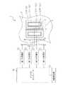
図6は、本発明に適用できる別のタッチセンサを説明するための情報入力装置のブロック図である。図6において、図1ないし図4中の符号と同一の符号は同等の部材を指しており、詳細な説明は省略する。(Second Embodiment)
FIG. 6 is a block diagram of an information input device for explaining another touch sensor applicable to the present invention. In FIG. 6, the same reference numerals as those in FIGS. 1 to 4 denote the same members, and detailed description thereof is omitted.
第1の実施形態例の静電容量用の受信電極11Bと人体通信用の受信電極12Bは離れて配され、第1の発振部21と第2の発振部25は同時に駆動されて信号を出力している。本例では、図6に示すように、静電容量用の受信電極11Bと人体通信用の受信電極12Bが共有電極として構成され、第1の発振部21が信号を出力している時は、第2の発振部25は信号を出力せず、第2の発振部25が信号を出力している時は、第1の発振部21は信号を出力しないように、信号が交互に出力されて(時分割されて)構成されてもよい。この場合、静電容量用の受信電極11Bと人体通信用の受信電極12Bを共用できるため、部品点数を少なくして操作面2を小さくでき、装置全体が小型化できる。 In the first embodiment, the
以上、本発明の実施形態例を説明したが、本発明は上記実施形態例に限定されるものではなく、本発明の趣旨を逸脱しない範囲で上記実施形態例を適宜に変形可能である。 The embodiment of the present invention has been described above. However, the present invention is not limited to the above-described embodiment, and can be appropriately modified without departing from the spirit of the present invention.
第1の実施形態例の近接センサ11は静電容量用センサであるが、操作面2への指の接近を検出する近接センサ11であれば、検出感度を高めた、人体通信用のセンサとしてもよい。この場合の検出感度は、静電容量用センサの検出感度と同様に操作面2から所定の距離離れた範囲に設定される。 The
また、第1の実施形態例では、操作面2に形成された最小検出領域3に、1つの近接センサと、1つの接触センサが設けられた場合を説明したが、1つの近接センサ11と複数の接触センサ12が設けられてもよく、この場合、例えば、1つの近接センサ11の外周に接触センサ12が正方形状に複数点在するように配置される。
また、操作面2に形成された最小検出領域3に、1つの接触センサ12と複数の近接センサ11が設けられてもよく、この場合、例えば、1つの接触センサ12の外周に近接センサ11が正方形状に複数点在するように配置される。
また、操作面2に形成された最小検出領域3には、複数の近接センサ11と複数の接触センサ12が設けられてもよく、この場合、例えば、近接センサ11が正方形状に複数点在するように配置され、この外周に、接触センサ12が正方形状に複数点在するように配置される。
よって、操作面2に形成された最小検出領域3に、少なくとも1つの近接センサと、少なくとも1つの接触センサを有することにより、操作性と検出感度が向上できる。In the first embodiment, the case where one proximity sensor and one contact sensor are provided in the
Further, one
Further, the
Therefore, by having at least one proximity sensor and at least one contact sensor in the
また、第1の実施形態例の最小検出領域3は、一辺が26mm以下の正方形内に形成されているが、これと同等の面積を有すれば、最小検出領域は、1mm以上の一辺を有する長方形に形成されてもよい。 Further, the
また、第1の実施形態例の接触センサ12は近接センサ11の外周に配されているが、近接センサ11が接触センサ12の外周に配されてもよい。
また、第1の実施形態例の近接センサ11と接触センサ12の導電パターンは入れ子状に形成されているが、近接センサ11と接触センサ12は、図7に示すように、互いに分離された導電パターンとして構成されてもよい。
また、以上の静電容量用の送信電極11Aは、静電容量用の受信電極11Bの外周に形成されているが、静電容量用の送信電極11Aは、静電容量用の受信電極11Bの内周に形成されてもよい。
また、以上の人体通信用の送信電極12Aは、人体通信用の受信電極12Bの内周に形成されているが、人体通信用の送信電極12Aは、人体通信用の受信電極12Bの外周に形成されてもよい。Further, although the
Moreover, although the conductive pattern of the
The
Further, the above-described
また、第1の実施形態例の静電容量用センサは、送信電極11Aと受信電極12Bの2つの電極により構成されているが、静電容量センサは1つの電極により構成されてもよい。この場合の電極には、第1の発振部21の入力が接続されると共に、第1の受信部22の出力が接続される。この場合、操作者の指の接近を検出する第1の閾値L1は第1の実施形態例より高く設定される。 In addition, although the capacitance sensor of the first embodiment is configured by two electrodes of the
また、第1の実施形態例では、操作者の指が操作面2に面接触した状態が検出され、振動発生部が第1期間動作し、その後、操作者の指が操作面2に面接触した状態から離れようとする状態が検出され、その後、振動発生部が第2期間動作する。そこで、振動発生部30が動作する第1期間内に、操作者の指が操作面2に面接触した状態から離れようとする状態が検出された際、振動発生部30は、第1期間の途中から連続して第2期間動作することが好ましい。
すなわち、操作者の指が操作面2に面接触した状態が検出され、振動発生部が第1期間動作し、その後、操作者の指が操作面2に面接触した状態から離れようとする状態が検出され、振動発生部が第2期間動作する場合には、操作者は常に同じクリック感を得られると限らず、操作性が低下してしまう恐れがある。
一方、本例では、操作者の指が操作面2に面接触した状態から離れようとした際、振動発生部は、第1期間の途中から連続して第2期間動作することにより、操作者は常に同じクリック感が得られ、操作性が低下しない。In the first embodiment, the state in which the operator's finger is in surface contact with the
That is, the state in which the operator's finger is in surface contact with the
On the other hand, in this example, when the operator's finger tries to leave the state in which the operator's finger is in surface contact with the
また、第1の実施形態例では、第2の発振部の出力信号は、1つの人体通信用の送信電極1に接続されていたが、接触センサ12は複数の送信電極12Aを有し、この送信電極12Aに信号を出力する1つの発振部を有し、この発振部の出力が複数の送信電極12Aにそれぞれ接続されていることが好ましい。
この場合、1つの発振部の出力を複数の送信電極に接続するため、装置が大幅に小型化できる。In the first embodiment, the output signal of the second oscillating unit is connected to one
In this case, since the output of one oscillating unit is connected to a plurality of transmission electrodes, the apparatus can be greatly reduced in size.
また、第1の実施形態例では、第1期間の振動発生部30の動作と第2期間の振動発生部30の動作は同一であるが、第1期間の振動発生部30の動作は、第2期間の振動発生部30の動作と異なることが好ましい。
この場合、操作者の指が接触センサに面接触した時と離れようとした時のクリック感の区別がしやすい。
具体的には、例えば、操作者の指が接触センサに接触した時に0.4秒間、連続動作し、指が接触センサから離れようとした時に0.1秒オン0.1秒オフを2回繰り返す断続動作をすると、操作者は、指が面接触センサに接触した時と離れようとした時のクリック感の区別が容易にでき、操作確認しやすい。In the first embodiment, the operation of the
In this case, it is easy to distinguish the feeling of clicking when the operator's finger makes surface contact with the contact sensor and when the operator tries to leave.
Specifically, for example, when the operator's finger touches the contact sensor, it continuously operates for 0.4 seconds, and when the finger tries to move away from the contact sensor, 0.1 second on and 0.1 second off twice. When the intermittent operation is repeated, the operator can easily distinguish the click feeling when the finger touches the surface contact sensor and when the finger tries to leave, and the operation can be easily confirmed.
また、第1の実施形態例の振動発生部30の第1期間と第2期間は連続0.4秒であるが、例えば、0.1秒オン0.1秒オフを2回繰り返す断続動作としてもよく、振動発生部30の連続動作期間や断続回数は、適宜設定できるものである。 Further, the first period and the second period of the
なお、本発明では、近接センサ11と接触センサ12を同時に駆動させた場合、近接センサ11と接触センサ12は混信しないように距離が離されたり、信号の振幅値が小さく構成されたりするものである。 In the present invention, when the
1 情報入力装置
2 操作面
3 最小検出領域
11 近接センサ
11A 静電容量用の送信電極
11B 静電容量用の受信電極
12 接触センサ
12A 人体通信用の送信電極
12B 人体通信用の受信電極
21 第1の発振部
22 第1の受信部
25 第2の発振部
26 第2の受信部
30 振動発生部
40 マイクロコンピュータ
A1 情報
L1 第1の閾値
L2 第2の閾値
DESCRIPTION OF
11B Electrostatic
Claims (9)
Translated fromJapanese前記近接センサより検出感度が低く前記操作面への近接物体の面接触を検出する接触センサと、
前記操作面を振動させる振動発生部を備え、
前記近接センサが近接物体の接近を検出すると、第1の所定の処理が行われ、
前記接触センサが近接物体の面接触を検出すると、前記振動発生部が第1期間動作し、
前記操作面から近接物体が離れようとする状態を前記接触センサが検出すると、前記振動発生部が第2期間動作して、
前記接触センサは、前記近接センサの外周にループ状に形成されていることを特徴とする情報入力装置。A proximity sensor that detects the proximity of a proximity object to the operation surface;
A contact sensor that has lower detection sensitivity than the proximity sensor and detects surface contact of a proximity object to the operation surface;
Comprising a vibration generating section for vibrating the operation surface;
When the proximity sensor detects the approach of a proximity object, a first predetermined process is performed,
When the contact sensor detects surface contact of a proximity object, the vibration generating unit operates for a first period,
When the contact sensor detects a state in which a proximity object is about to leave the operation surface, the vibration generating unit operatesfor a second period,
The information input device according toclaim 1, wherein the contact sensor is formed in a loop shape on an outer periphery of the proximity sensor .
前記送信電極に信号を出力する1つの発振部を有し、One oscillating unit for outputting a signal to the transmission electrode;
前記発振部の出力が前記送信電極にそれぞれ接続されていることを特徴とする請求項1ないし7のいずれかに記載の情報入力装置。8. The information input device according to claim 1, wherein an output of the oscillating unit is connected to the transmission electrode.
Priority Applications (1)
| Application Number | Priority Date | Filing Date | Title |
|---|---|---|---|
| JP2013045203AJP6095420B2 (en) | 2013-03-07 | 2013-03-07 | Information input device |
Applications Claiming Priority (1)
| Application Number | Priority Date | Filing Date | Title |
|---|---|---|---|
| JP2013045203AJP6095420B2 (en) | 2013-03-07 | 2013-03-07 | Information input device |
Publications (2)
| Publication Number | Publication Date |
|---|---|
| JP2014174660A JP2014174660A (en) | 2014-09-22 |
| JP6095420B2true JP6095420B2 (en) | 2017-03-15 |
Family
ID=51695853
Family Applications (1)
| Application Number | Title | Priority Date | Filing Date |
|---|---|---|---|
| JP2013045203AExpired - Fee RelatedJP6095420B2 (en) | 2013-03-07 | 2013-03-07 | Information input device |
Country Status (1)
| Country | Link |
|---|---|
| JP (1) | JP6095420B2 (en) |
Families Citing this family (8)
| Publication number | Priority date | Publication date | Assignee | Title |
|---|---|---|---|---|
| JP6625726B2 (en) | 2016-03-04 | 2019-12-25 | 株式会社ソニー・インタラクティブエンタテインメント | Control device and control program |
| CN108885501A (en)* | 2016-05-12 | 2018-11-23 | 西奎公司 | Incuded using the controller of capacitance sensing |
| JP6626576B2 (en)* | 2016-07-21 | 2019-12-25 | 株式会社ソニー・インタラクティブエンタテインメント | Operation device and control system |
| US11344797B2 (en) | 2016-07-26 | 2022-05-31 | Sony Interactive Entertainment Inc. | Information processing system, operation device, and operation device control method with multi-mode haptic feedback |
| EP3493030B1 (en) | 2016-07-26 | 2021-06-23 | Sony Interactive Entertainment Inc. | Operation device and operation device control method |
| WO2019064518A1 (en) | 2017-09-29 | 2019-04-04 | 株式会社ソニー・インタラクティブエンタテインメント | Operation device and control apparatus therefor |
| JP6949982B2 (en) | 2017-10-27 | 2021-10-13 | 株式会社ソニー・インタラクティブエンタテインメント | Operation device |
| JP7054618B2 (en)* | 2017-11-29 | 2022-04-14 | 株式会社ジャパンディスプレイ | Proximity sensor |
Family Cites Families (5)
| Publication number | Priority date | Publication date | Assignee | Title |
|---|---|---|---|---|
| TWI300529B (en)* | 2005-10-05 | 2008-09-01 | Holtek Semiconductor Inc | Proximaty sensing device and sensing method thereof |
| JP4897596B2 (en)* | 2007-07-12 | 2012-03-14 | ソニー株式会社 | INPUT DEVICE, STORAGE MEDIUM, INFORMATION INPUT METHOD, AND ELECTRONIC DEVICE |
| JP2010257012A (en)* | 2009-04-22 | 2010-11-11 | Panasonic Corp | Information terminal device and input control method |
| JP2011048409A (en)* | 2009-07-29 | 2011-03-10 | Kyocera Corp | Input device and control method of input device |
| JP5773617B2 (en)* | 2010-11-02 | 2015-09-02 | キヤノン株式会社 | Display control apparatus and display control method |
- 2013
- 2013-03-07JPJP2013045203Apatent/JP6095420B2/ennot_activeExpired - Fee Related
Also Published As
| Publication number | Publication date |
|---|---|
| JP2014174660A (en) | 2014-09-22 |
Similar Documents
| Publication | Publication Date | Title |
|---|---|---|
| JP6095420B2 (en) | Information input device | |
| US9977519B2 (en) | Active pen with bidirectional communication | |
| US9898128B2 (en) | Sensor signal processing circuit and sensor signal processing method | |
| EP2725459B1 (en) | Touch pen using delay device and touch input method thereof and touch input system and method thereof | |
| CN104656973A (en) | Coordinate input device and mobile terminal | |
| CN102109923B (en) | Pointing body, position detection device and position detection method | |
| US9448670B2 (en) | Methods and systems for hybrid multi-touch capacitive (MTC) and active stylus touch device | |
| US20110193818A1 (en) | Proximity-sensing panel | |
| CN106201049B (en) | Position detection device and position detection method | |
| US12008199B2 (en) | Touch apparatus and touch detection method thereof | |
| KR102764364B1 (en) | Touch apparatus and touch detection method thereof | |
| CN111538424B (en) | Active pen with improved interference performance | |
| EP3533161B1 (en) | User-worn device and touch-device for ultrasonic data transmission | |
| KR102224833B1 (en) | Touch apparatus | |
| TWI622902B (en) | Touch system and stylus device tilt state determination method | |
| KR20230165742A (en) | Touch device and touch detection method thereof | |
| CN105446563B (en) | Hybrid sensing with reduced latency | |
| CN102436333B (en) | Input device compatible with capacitance positioning and electromagnet positioning and input method thereof | |
| KR20160025284A (en) | Coordinates measurement devices, coordinates measurement systems and methods of measuring coordinates | |
| KR102459359B1 (en) | Touch apparatus | |
| KR101755945B1 (en) | Pressure sensitive pointing apparatus and information processing apparatus using frequency filtering | |
| KR102170298B1 (en) | Touch device and touch detection method thereof | |
| KR101716059B1 (en) | Pressure sensitive pointing apparatus and information processing apparatus using frequency tracking | |
| KR20220145806A (en) | Touch apparatus | |
| CN115480667A (en) | Capacitive communication channel for auxiliary devices |
Legal Events
| Date | Code | Title | Description |
|---|---|---|---|
| A621 | Written request for application examination | Free format text:JAPANESE INTERMEDIATE CODE: A621 Effective date:20160205 | |
| A131 | Notification of reasons for refusal | Free format text:JAPANESE INTERMEDIATE CODE: A131 Effective date:20161121 | |
| A977 | Report on retrieval | Free format text:JAPANESE INTERMEDIATE CODE: A971007 Effective date:20161124 | |
| A601 | Written request for extension of time | Free format text:JAPANESE INTERMEDIATE CODE: A601 Effective date:20170119 | |
| A521 | Written amendment | Free format text:JAPANESE INTERMEDIATE CODE: A523 Effective date:20170203 | |
| TRDD | Decision of grant or rejection written | ||
| A01 | Written decision to grant a patent or to grant a registration (utility model) | Free format text:JAPANESE INTERMEDIATE CODE: A01 Effective date:20170210 | |
| A61 | First payment of annual fees (during grant procedure) | Free format text:JAPANESE INTERMEDIATE CODE: A61 Effective date:20170214 | |
| R150 | Certificate of patent or registration of utility model | Ref document number:6095420 Country of ref document:JP Free format text:JAPANESE INTERMEDIATE CODE: R150 | |
| R250 | Receipt of annual fees | Free format text:JAPANESE INTERMEDIATE CODE: R250 | |
| LAPS | Cancellation because of no payment of annual fees |