JP6091439B2 - Image forming apparatus - Google Patents
Image forming apparatusDownload PDFInfo
- Publication number
- JP6091439B2 JP6091439B2JP2014011489AJP2014011489AJP6091439B2JP 6091439 B2JP6091439 B2JP 6091439B2JP 2014011489 AJP2014011489 AJP 2014011489AJP 2014011489 AJP2014011489 AJP 2014011489AJP 6091439 B2JP6091439 B2JP 6091439B2
- Authority
- JP
- Japan
- Prior art keywords
- mounting
- contact
- contact portion
- toner
- toner container
- Prior art date
- Legal status (The legal status is an assumption and is not a legal conclusion. Google has not performed a legal analysis and makes no representation as to the accuracy of the status listed.)
- Active
Links
Images


Classifications
- G—PHYSICS
- G03—PHOTOGRAPHY; CINEMATOGRAPHY; ANALOGOUS TECHNIQUES USING WAVES OTHER THAN OPTICAL WAVES; ELECTROGRAPHY; HOLOGRAPHY
- G03G—ELECTROGRAPHY; ELECTROPHOTOGRAPHY; MAGNETOGRAPHY
- G03G21/00—Arrangements not provided for by groups G03G13/00 - G03G19/00, e.g. cleaning, elimination of residual charge
- G03G21/16—Mechanical means for facilitating the maintenance of the apparatus, e.g. modular arrangements
- G03G21/18—Mechanical means for facilitating the maintenance of the apparatus, e.g. modular arrangements using a processing cartridge, whereby the process cartridge comprises at least two image processing means in a single unit
- G03G21/1839—Means for handling the process cartridge in the apparatus body
- G—PHYSICS
- G03—PHOTOGRAPHY; CINEMATOGRAPHY; ANALOGOUS TECHNIQUES USING WAVES OTHER THAN OPTICAL WAVES; ELECTROGRAPHY; HOLOGRAPHY
- G03G—ELECTROGRAPHY; ELECTROPHOTOGRAPHY; MAGNETOGRAPHY
- G03G21/00—Arrangements not provided for by groups G03G13/00 - G03G19/00, e.g. cleaning, elimination of residual charge
- G03G21/16—Mechanical means for facilitating the maintenance of the apparatus, e.g. modular arrangements
- G03G21/1642—Mechanical means for facilitating the maintenance of the apparatus, e.g. modular arrangements for connecting the different parts of the apparatus
- G03G21/1652—Electrical connection means
- G—PHYSICS
- G03—PHOTOGRAPHY; CINEMATOGRAPHY; ANALOGOUS TECHNIQUES USING WAVES OTHER THAN OPTICAL WAVES; ELECTROGRAPHY; HOLOGRAPHY
- G03G—ELECTROGRAPHY; ELECTROPHOTOGRAPHY; MAGNETOGRAPHY
- G03G21/00—Arrangements not provided for by groups G03G13/00 - G03G19/00, e.g. cleaning, elimination of residual charge
- G03G21/16—Mechanical means for facilitating the maintenance of the apparatus, e.g. modular arrangements
- G03G21/1661—Mechanical means for facilitating the maintenance of the apparatus, e.g. modular arrangements means for handling parts of the apparatus in the apparatus
- G03G21/1676—Mechanical means for facilitating the maintenance of the apparatus, e.g. modular arrangements means for handling parts of the apparatus in the apparatus for the developer unit
- G—PHYSICS
- G03—PHOTOGRAPHY; CINEMATOGRAPHY; ANALOGOUS TECHNIQUES USING WAVES OTHER THAN OPTICAL WAVES; ELECTROGRAPHY; HOLOGRAPHY
- G03G—ELECTROGRAPHY; ELECTROPHOTOGRAPHY; MAGNETOGRAPHY
- G03G15/00—Apparatus for electrographic processes using a charge pattern
- G03G15/06—Apparatus for electrographic processes using a charge pattern for developing
- G03G15/08—Apparatus for electrographic processes using a charge pattern for developing using a solid developer, e.g. powder developer
- G03G15/0822—Arrangements for preparing, mixing, supplying or dispensing developer
- G03G15/0863—Arrangements for preparing, mixing, supplying or dispensing developer provided with identifying means or means for storing process- or use parameters, e.g. an electronic memory
- G—PHYSICS
- G03—PHOTOGRAPHY; CINEMATOGRAPHY; ANALOGOUS TECHNIQUES USING WAVES OTHER THAN OPTICAL WAVES; ELECTROGRAPHY; HOLOGRAPHY
- G03G—ELECTROGRAPHY; ELECTROPHOTOGRAPHY; MAGNETOGRAPHY
- G03G15/00—Apparatus for electrographic processes using a charge pattern
- G03G15/06—Apparatus for electrographic processes using a charge pattern for developing
- G03G15/08—Apparatus for electrographic processes using a charge pattern for developing using a solid developer, e.g. powder developer
- G03G15/0822—Arrangements for preparing, mixing, supplying or dispensing developer
- G03G15/0865—Arrangements for supplying new developer
- G03G15/0875—Arrangements for supplying new developer cartridges having a box like shape
- G—PHYSICS
- G03—PHOTOGRAPHY; CINEMATOGRAPHY; ANALOGOUS TECHNIQUES USING WAVES OTHER THAN OPTICAL WAVES; ELECTROGRAPHY; HOLOGRAPHY
- G03G—ELECTROGRAPHY; ELECTROPHOTOGRAPHY; MAGNETOGRAPHY
- G03G15/00—Apparatus for electrographic processes using a charge pattern
- G03G15/80—Details relating to power supplies, circuits boards, electrical connections
- G—PHYSICS
- G03—PHOTOGRAPHY; CINEMATOGRAPHY; ANALOGOUS TECHNIQUES USING WAVES OTHER THAN OPTICAL WAVES; ELECTROGRAPHY; HOLOGRAPHY
- G03G—ELECTROGRAPHY; ELECTROPHOTOGRAPHY; MAGNETOGRAPHY
- G03G21/00—Arrangements not provided for by groups G03G13/00 - G03G19/00, e.g. cleaning, elimination of residual charge
- G03G21/16—Mechanical means for facilitating the maintenance of the apparatus, e.g. modular arrangements
- G03G21/18—Mechanical means for facilitating the maintenance of the apparatus, e.g. modular arrangements using a processing cartridge, whereby the process cartridge comprises at least two image processing means in a single unit
- G03G21/1839—Means for handling the process cartridge in the apparatus body
- G03G21/1867—Means for handling the process cartridge in the apparatus body for electrically connecting the process cartridge to the apparatus, electrical connectors, power supply
- G—PHYSICS
- G03—PHOTOGRAPHY; CINEMATOGRAPHY; ANALOGOUS TECHNIQUES USING WAVES OTHER THAN OPTICAL WAVES; ELECTROGRAPHY; HOLOGRAPHY
- G03G—ELECTROGRAPHY; ELECTROPHOTOGRAPHY; MAGNETOGRAPHY
- G03G2221/00—Processes not provided for by group G03G2215/00, e.g. cleaning or residual charge elimination
- G03G2221/16—Mechanical means for facilitating the maintenance of the apparatus, e.g. modular arrangements and complete machine concepts
- G03G2221/1651—Mechanical means for facilitating the maintenance of the apparatus, e.g. modular arrangements and complete machine concepts for connecting the different parts
- G03G2221/166—Electrical connectors
Landscapes
- Physics & Mathematics (AREA)
- General Physics & Mathematics (AREA)
- Engineering & Computer Science (AREA)
- Computer Vision & Pattern Recognition (AREA)
- Electrophotography Configuration And Component (AREA)
- Dry Development In Electrophotography (AREA)
Description
Translated fromJapanese本発明は、装着部に着脱可能に支持されるトナーコンテナなどの交換部材を備え、前記交換部材の装着時に交換部材の第1接触部が装着部の第2接触部に接触される画像形成装置に関する。 The present invention includes an exchange member such as a toner container that is detachably supported by a mounting portion, and the first contact portion of the replacement member is brought into contact with the second contact portion of the mounting portion when the replacement member is mounted. About.
電子写真方式によって印刷用紙に画像を形成する複写機やプリンター等の画像形成装置には現像装置が搭載されている。現像装置の内部にはトナーを含む現像剤が収容されている。現像装置は、感光体ドラム等の像担持体上に形成された静電潜像を前記現像剤に含まれるトナーによって現像する。現像が行われることにより現像装置の内部のトナーが減少する。そのため、画像形成装置は、トナーが収容されたトナーコンテナ(交換部材)を備えており、トナーコンテナから現像装置へトナーを補給するように構成されている。また、前記トナーコンテナは、画像形成装置に対して着脱可能に構成されており、トナーコンテナ内のトナーが空になると、トナーが充填された新たなトナーコンテナに交換される。 A developing device is mounted on an image forming apparatus such as a copying machine or a printer that forms an image on printing paper by an electrophotographic method. A developer containing toner is accommodated in the developing device. The developing device develops an electrostatic latent image formed on an image carrier such as a photosensitive drum with toner contained in the developer. As a result of the development, the toner in the developing device is reduced. For this reason, the image forming apparatus includes a toner container (exchange member) that contains toner, and is configured to replenish the toner from the toner container to the developing device. The toner container is configured to be detachable from the image forming apparatus. When the toner in the toner container becomes empty, the toner container is replaced with a new toner container filled with toner.
この種のトナーコンテナの表面には、トナーコンテナやトナーに関する情報などが記憶されたメモリーチップと称される記憶部が取り付けられている(特許文献1参照)。このため、画像形成装置にトナーコンテナが装着されると、画像形成装置に設けられた読取部の接続端子と前記記憶部の接続端子とが電気的に接触し、これにより、記憶部に記憶されている情報が読取部によって読み取られる。 On the surface of this type of toner container, a storage unit called a memory chip in which information about the toner container and toner is stored is attached (see Patent Document 1). For this reason, when the toner container is attached to the image forming apparatus, the connection terminal of the reading unit provided in the image forming apparatus and the connection terminal of the storage unit are in electrical contact with each other, thereby being stored in the storage unit. Is read by the reading unit.
ところで、画像形成装置に用いられる部品は、設計寸法どおりに形成されず、寸法公差を有する場合がある。また、画像形成装置が設置される環境(温度や湿度など)によって部品が伸縮してサイズが変動する場合がある。このため、画像形成装置に用いられるトナーコンテナやこれを装着するための装着部の寸法にばらつきが生じる。このような寸法ばらつきは、トナーコンテナが装着部に装着された状態で前記読取部及び前記記憶部それぞれの接続端子の接触不良を生じさせる。なお、特許文献1には、装着側の接続端子をバネ部材で構成してそのバネ力によって前記接続端子を記憶部の接続端子に付勢させる機構が開示されている。 By the way, parts used in the image forming apparatus are not formed according to the design dimensions, and may have a dimensional tolerance. Further, the size may vary due to expansion and contraction of components depending on the environment (temperature, humidity, etc.) in which the image forming apparatus is installed. For this reason, variations occur in the dimensions of the toner container used in the image forming apparatus and the mounting portion for mounting the toner container. Such a dimensional variation causes a contact failure between the connection terminals of the reading unit and the storage unit when the toner container is mounted on the mounting unit.
しかしながら、前掲の特許文献1の構成であっても、トナーコンテナ及び装着部の寸法公差による位置ズレによって、前記付勢力がばらつく。そのため、接続端子同士を一定の付勢力で接触させることができない。これにより、接続端子同士が互いに接触していたとしても、接続端子が経年劣化や接触摩擦によって導通し難くなった場合に、付勢力のばらつきが原因で、接触不良が生じるおそれがある。 However, even in the configuration of
本発明は前記事情に鑑みてなされたものであり、その目的は、交換部材と装着部とを確実に安定して電気的に接触させることが可能な画像形成装置を提供することにある。 The present invention has been made in view of the above circumstances, and an object of the present invention is to provide an image forming apparatus capable of reliably and stably bringing an exchange member and a mounting portion into electrical contact.
本発明の一の局面に係る画像形成装置は、装置本体に設けられた装着部と、 前記装着部に着脱可能に支持される交換部材と、を備える。前記交換部材は、第1接触部を有する。前記第1接触部は、前記装着部に対する前記交換部材の着脱方向に直交する第1方向の一方側の側面に設けられている。この第1接触部は、接触されることにより電気的に導通可能なものである。前記装着部は、第2接触部と、支持部とを有する。前記第2接触部は、前記第1接触部と接触して電気的に接続される。前記支持部は、前記交換部材が前記装着部に装着される装着動作に伴い前記交換部材に係合して前記第1接触部が前記第2接触部に接触する予め定められた設定位置に前記第1接触部を移動させる。 An image forming apparatus according to an aspect of the present invention includes a mounting portion provided in an apparatus main body, and an exchange member that is detachably supported by the mounting portion. The replacement member has a first contact portion. The first contact portion is provided on a side surface on one side in a first direction orthogonal to the attaching / detaching direction of the replacement member with respect to the mounting portion. The first contact portion can be electrically connected by being contacted. The mounting portion includes a second contact portion and a support portion. The second contact portion is in contact with and electrically connected to the first contact portion. The support portion is engaged with the replacement member during a mounting operation in which the replacement member is mounted on the mounting portion, and the first contact portion contacts the second contact portion at a predetermined setting position. The first contact portion is moved.
本発明によれば、画像形成装置において交換部材と装着部とを確実に安定して電気的に接触させることが可能である。 According to the present invention, in the image forming apparatus, the replacement member and the mounting portion can be reliably and electrically contacted.
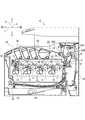
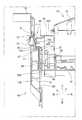
以下、図面を参照しながら、本発明の実施形態に係る画像形成装置10について説明する。以下の説明では、画像形成装置10が平坦面に設置された状態(図1に示される状態)を基準として上下方向6を定義する。また、図1の紙面に対して左側の面を画像形成装置10の正面として前後方向7を定義する。また、図1の画像形成装置10を正面側から見て左右方向8(図1の紙面に垂直な方向)を定義する。 Hereinafter, an
[画像形成装置10の概略構成]
画像形成装置10は、少なくとも印刷機能を備えた画像形成装置である。図1に示されるように、画像形成装置10は、所謂タンデムタイプのカラープリンターである。この画像形成装置10は、トナーを含む現像剤を用いて、シート状の印刷用紙(記録媒体)に画像を印刷する。なお、画像形成装置10は、印刷機能を備えたものであればよく、例えば、前記印刷機能を含む複数の機能を備えた複合機や、FAX装置、複写機などの画像形成装置であってもよい。もちろん、カラー画像を形成するものでなく、単一色の画像を形成するものであってもよい。[Schematic Configuration of Image Forming Apparatus 10]
The
図1に示されるように、画像形成装置10は、主として、4つの画像形成部21と、中間転写ベルト22と、給紙装置25と、定着装置26と、二次転写装置27と、露光装置24と、4つのトナーコンテナ50(50A〜50D)と、を備えている。これらの構成要素は、画像形成装置10の外部フレーム(不図示)や内部フレーム(不図示)などを構成する筐体28(本発明の装置本体の一例)に取り付けられている。なお、トナー容器としてのトナーコンテナ50は画像形成装置10における交換部材の一例である。 As shown in FIG. 1, the
4つの画像形成部21は、筐体28の内部において、前後方向8に沿って並設されている。各画像形成部21は、感光体ドラム11にトナー像を形成し、そのトナー像を矢印19の方向へ移動中の中間転写ベルト22へ順次重ね合わせて転写する電子写真方式の画像形成部である。図1に示される例では、中間転写ベルト22の移動方向(矢印19方向)の下流側から順に、ブラック色、イエロー色、シアン色、マゼンタ色に対応する画像形成部21がその順番で一列に配置されている。 The four image forming units 21 are arranged in parallel along the front-rear direction 8 inside the
画像形成部21は、所謂電子写真方式に基づいて印刷用紙Pに画像を形成する画像形成処理を実行する。画像形成部21は、不図示のネットワーク通信部を介して外部から入力された画像データに基づいて、印刷用紙に画像を印刷する。画像形成部21は、感光体ドラム11、帯電装置(不図示)、現像装置12、一次転写装置13等を備えている。感光体ドラム11は、その表面にトナー像を担持する。前記帯電装置は、対応する感光体ドラム11の表面を所定の電位に帯電させる。帯電された感光体ドラム11に対して露光装置24は画像データに応じたレーザー光を走査する。これにより、感光体ドラム11の表面に静電潜像が書き込まれる。現像装置12は、感光体ドラム11上の静電潜像にトナーを付着させて、前記静電潜像をトナーによって現像する。一次転写装置13は、回転する感光体ドラム11上のトナー像を中間転写ベルト5に転写する。なお、図1には示されていないが、各画像形成部21は、感光体ドラム11上に残存したトナー像を除去するクリーニング装置も備えている。 The image forming unit 21 executes an image forming process for forming an image on the printing paper P based on a so-called electrophotographic system. The image forming unit 21 prints an image on a print sheet based on image data input from the outside via a network communication unit (not shown). The image forming unit 21 includes a
中間転写ベルト22は、画像形成部21の上方に配置されている。中間転写ベルト22は、例えばゴムやウレタン等の素材からなる無端環状のベルトである。中間転写ベルト22は、駆動プーリー31及び従動プーリー32によって回転駆動可能に支持されており、これにより、ベルト面が水平な状態で前後方向8に延在している。駆動プーリー31は定着装置26に近い後方位置(図1において右側の位置)に配置されており、従動プーリー32は定着装置26から遠い前方位置(図1において左側の位置)に配置されている。駆動プーリー31及び従動プーリー32によって支持されることにより、中間転写ベルト22は、その表面が各感光体ドラム11の表面に接しながら移動(走行)可能となる。そして、中間転写ベルト22は、その表面が感光体ドラム11と一次転写装置13との間を通過する際に、感光体ドラム11からトナー像が順に重ね合わせて転写される。 The
二次転写装置27は、筐体28の後方側に配置されている。二次転写装置27は、中間転写ベルト22に転写された複数色からなるトナー像を給紙装置25の給紙トレイ25Aから搬送されてきた印刷用紙に転写する。トナー像が転写された印刷用紙は、定着装置26に搬送される。定着装置26は、印刷用紙に転写されたトナー像を熱によってその印刷用紙に定着させる。定着装置26は、高温に加熱された加熱ローラー26Aと、この加熱ローラー26Aに対向配置された加圧ローラー26Bとを有する。定着装置26に搬送された印刷用紙は、加熱ローラー26Aと加圧ローラー26Bとの間のニップ部で所定の付勢力によって挟持されつつ搬送されることにより、トナー像が印刷用紙に溶着される。その後、印刷用紙は、筐体28の上部に設けられた排紙トレイ29に排出される。 The
このように、画像形成装置10は、複数の画像形成部21によって各色のトナー像を走行中の中間転写ベルト22上に重ねて転写することにより、カラーのトナー像を中間転写ベルト22の表面に形成させる。そして、そのカラーのトナー像を二次転写装置27が中間転写ベルト22から印刷用紙に転写する。これにより、印刷用紙上にカラー画像が形成される。なお、中間転写ベルト22を搬送ベルトとして用い、その搬送ベルト上に搬送される印刷用紙にトナー像が直接に重ね合わせて転写される構成や、中間転写ベルト22に代えてローラー状の中間転写部材を用いることも他の実施例として考えられる。 As described above, the
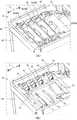
4つのトナーコンテナ50(50A〜50D)は、中間転写ベルト22の上方に配置されている。4つのトナーコンテナ50は、筐体28の内部において、中間転写ベルト22に沿って前後方向8に一列に並んで設けられている。トナーコンテナ50は、対応する色の現像装置12にトナーを供給するように構成されている。図2に示されるように、筐体28の内部には、トナーコンテナ50を装着するための装着部40が設けられている。本実施形態では、図2に示されるように、筐体28の上部のトップカバー33が筐体28に支軸33Aを中心に開閉可能に支持されており、そのトップカバー33が上方(開方向)へ回動されると、トナーコンテナ50が装着される装着部40が露出される。各トナーコンテナ50は、装着部40に形成された4つの収容スペース41に収容された状態で装着部40に装着される。 The four toner containers 50 (50 </ b> A to 50 </ b> D) are disposed above the
各トナーコンテナ50には、画像形成部21の各色に対応する色のトナーが収容されている。具体的には、各トナーコンテナ50(50A〜50D)それぞれには、ブラック色、イエロー色、シアン色、マゼンタ色のトナーが個別に収容されている。図2に示されるように、4つのトナーコンテナ50のうち、最も後方に位置するトナーコンテナ50Aは他のトナーコンテナ50B〜50Dよりも大容量タイプのものであり、このトナーコンテナ50Aにブラック色のトナーが収容されている。また、トナーコンテナ50B〜50Dはいずれも同じ形状であり同じ容量のものである。トナーコンテナ50Bにイエロー色のトナーが収容されており、トナーコンテナ50Cにシアン色のトナーが収容されており、トナーコンテナ50Dにマゼンタ色のトナーが収容されている。 Each
[トナーコンテナ50の構成]
以下、トナーコンテナ50の構成について説明する。ここで、大容量タイプのトナーコンテナ50Aと他のトナーコンテナ50B〜50Dとは、トナーの収容部のサイズが異なる以外は同じ構成である。そのため、以下の説明では、トナーコンテナ50A〜50Dをトナーコンテナ50として説明する。[Configuration of Toner Container 50]
Hereinafter, the configuration of the
トナーコンテナ50は、現像装置12にトナーを供給するものである。トナーコンテナ50は、筐体28に設けられた装着部40(図2参照)に対して着脱可能に支持されるものであり、交換部材の一例である。トナーコンテナ50は、筐体28の上側の開口から挿入されて、装着部40の各収容スペース41に収容される。 The
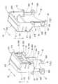
図3に示されるように、トナーコンテナ50は、ハウジング51と、蓋体52と、メモリーホルダー60(本発明の保持部の一例)とを備えている。 As shown in FIG. 3, the
ハウジング51は、トナーが収容される収容部であり、一方向に長い箱形状に形成されている。ハウジング51は、上面に開口が設けられており、その開口を塞ぐように蓋体52が設けられている。ハウジング51及び蓋体52によって形成される内部空間に、現像装置12による現像処理に使用されるトナーが収容される。ハウジング51及び蓋体52は、溶融した合成樹脂を金型に流し込み、射出成形(インジェクション成形)することによって形成される合成樹脂製品である。ハウジング51及び蓋体52の材料は、熱可塑性の合成樹脂を使用することができる。具体的には、ABS樹脂やPET樹脂(ポリエチレンテレフタラート)、或いはこれらを主成分とする合成樹脂がハウジング51及び蓋体52の材料として用いられる。 The
ハウジング51の長手方向D1の一方側の側面54Aにメモリーホルダー60が取り付けられている。具体的には、側面54Aに突出部55が一体に形成されており、その突出部55にメモリーホルダー60が取り付けられている。 A
突出部55は、長手方向D1の外側へ突出する矩形状に屈曲された板形状のものであり、短手方向D2の両側に位置する側壁55A,55Bと、各側壁55A,55Bの上端を連接する上壁55Cと、を有する。側壁55A,55Bは互いに平行であり、その外側面は平坦に形成されている。上壁55C及び側壁55A,55Bによって囲まれた突出部55の内部にメモリーホルダー60が取り付けられる。なお、メモリーホルダー60の取付構造については後述する。 The protruding
突出部55は、トナーコンテナ50が装着部40に装着される際に、装着部40が備えるガイド溝70(図6参照)に挿入されて、トナーコンテナ50の着脱方向にトナーコンテナ50を案内する。このとき、突出部55の側壁55A,55Bがガイド溝70に当接して、ガイド溝70によるガイド方向(トナーコンテナ50の着脱方向と同方向)へ案内される。つまり、突出部55は、装着部40に対してトナーコンテナ50を着脱方向に案内するガイド部材でもある。 The protruding
側壁55A,55Bそれぞれの概ね中央部には、長手方向D1に長い長孔56が形成されている。図3では、側壁55B側の長孔56は他の部材により隠れているため図示されていない。この長孔56は、メモリーホルダー60が備える後述のガイド軸62を長手方向D1に案内して、メモリーホルダー60を側面54Aに対して接離する方向へ移動させる役割を担っている。また、長孔56よりも下方であって、側壁55A,55Bの下端部付近には、軸孔57が形成されている。この軸孔57は、メモリーホルダー60が備える後述の回動軸63が挿通されて、回動軸63を軸支する。 A
図4に示されるように、メモリーホルダー60は、突出部55の内部に部分的に収容されるホルダー本体61と、突出部55の長孔56に挿通されるガイド軸62と、突出部55の軸孔57に回動可能に支持される回動軸63とを有する。メモリーホルダー60は合成樹脂を射出成形することにより形成される合成樹脂製品である。このため、ホルダー本体61と、ガイド軸62と、回動軸63とは一体に形成されている。 As shown in FIG. 4, the
ホルダー本体61は、内部が空洞の直方体形状に形成されている。突出部55の内部側に配置されるホルダー本体61の裏面61Bは、その全域が開口されている。ホルダー本体61の表面61Aには、チップメモリーやフラッシュメモリーなどの記憶部(不図示)の接続端子65(65A〜65D)が設けられている。これら4つの接続端子65は、導電材が接触されることにより電気的に前記導電材と導通可能なものであり、本発明の第1接触部の一例である。4つの接続端子65は、表面61Aにおいて幅方向D2に並んで配置されている。4つの接続端子65A〜65Dは、例えば銅箔からなる電極である。接続端子65Aは接地電極であり、接続端子65B,65Cは信号電極であり、接続端子65Dは電源電極である。本実施形態では、トナーコンテナ50が装着部40に装着される際に、装着部40が備える後述の接続端子73(図6(A)参照)に対して、接続端子65Aが一番に接触し、その次に接続端子65Dが接触し、最後に接続端子65B,65Cが接触するように、各接続端子65の電極長さが定められている。 The holder
前記記憶部は、トナーコンテナ50に収容されたトナーに関する情報を記憶している。トナーに関する情報の一例として、未使用のトナーコンテナ50に含まれるトナーの量や、トナーの残量、トナーが収容された時期、収容されたトナーが適用可能な条件などが該当する。なお、前記記憶部は、ホルダー本体61の裏側或いは側面54Aに固定されており、信号線や電源線などを含むワイヤーハーネスによって接続端子65に接続されている。 The storage unit stores information on toner stored in the
ホルダー本体61の幅方向D2の両方の側面61Cにガイド軸62が設けられている。ガイド軸62は、ホルダー本体61の下端部61Dの近傍に設けられている。ガイド軸62は、下端部61Dにおいて裏面61B側の位置に設けられている。ガイド軸62は、断面形状が円形の軸であり、側面61Cから外側へ突出している。このガイド軸62が突出部55の長孔56に挿通される。なお、ガイド軸62の突出長さは、長孔56に挿通されたときに突出部55の側壁55A,55Bの外側面に突出しない長さに定められている。
メモリーホルダー60は、ホルダー本体61の下端部61Dから下方に延出するアーム部66を有する。アーム部66の幅方向D2の両方の側面66Aに回動軸63が設けられている。回動軸63は、アーム部66の下端部66Bの近傍に設けられている。回動軸63は、断面形状が円形の軸であり、側面66Aから外側へ突出している。この回動軸63が突出部55の軸孔57に挿通される。なお、回動軸63の突出長さは、軸孔57に軸支されたときに突出部55の側壁55A,55Bの外側面に突出しない長さに定められている。 The
このように、メモリーホルダー60が構成されているため、回動軸63を軸孔57に支持させ、ガイド軸62を長孔56に挿通させることにより、メモリーホルダー60が突出部55に取り付けられる。具体的には、メモリーホルダー60は、回動軸63を回動中心として回動可能なように突出部55に支持される。上述したように、突出部55はトナーコンテナ50の長手方向D1の一方の側面54Aに設けられている。そのため、突出部55にメモリーホルダー60が取り付けられることは、接続端子65が、メモリーホルダー60及び突出部55を介して、トナーコンテナ50の側面54Aに設けられていることを意味する。つまり、接続端子65は、メモリーホルダー60及び突出部55を介して、トナーコンテナ50の側面54Aに設けられている。 Thus, since the
突出部55に対するメモリーホルダー60の回動範囲は、長孔56の長さを適宜設定することにより決定される。本実施形態では、メモリーホルダー60は、第1姿勢(図9(A)に示される姿勢)と、第2姿勢(図9(E)に示される姿勢)との間で回動軸63を中心に回動可能なように突出部55に支持されている。ここで、前記第1姿勢は、ホルダー本体61の裏面61B側が突出部55の内部に部分的に没入して側面54Aに最も接近する姿勢(図9(A)参照)である。また、前記第2姿勢は、ホルダー本体61が突出部55から最大に引き出されて側面54Aから最も離間した姿勢(図9(E)参照)である。このようにメモリーホルダー60が回動可能に支持されるため、メモリーホルダー60は、側面54Aに対して接離する方向へ変位可能となる。つまり、メモリーホルダー60は、側面54Aに対して接離する方向へ移動可能なように突出部55に支持されている。
そして、メモリーホルダー60が側面54Aから最も離間した前記第2姿勢になると、接続端子65が装着部40側の後述の接続端子73へ引き寄せられて、前記第2姿勢に応じた位置(図9(E)に示される位置)に移動される。The rotation range of the
When the
また、トナーコンテナ50には、2つの係合片67(本発明の被係合部の一例)が設けられている。具体的には、図4に示されるように、係合片67は、トナーコンテナ50が備えるメモリーホルダー60に一体に形成されている。係合片67は、後述するカバー77の傾斜面77A(図8参照)によって係合される部分である。係合片67は、ホルダー本体61の下端部61Dの表面61A側に形成されている。言い換えると、係合片67は、ホルダー本体61の表面61Aの下端に形成されている。係合片67は、方面61Aの下端において幅方向D2の両端それぞれに設けられている。係合片67は、ホルダー本体61の下端部61Dから下方へ延びる爪形状に形成されている。 Further, the
メモリーホルダー60のアーム部66には、回動軸63よりも下方へ延びる突出片68が設けられている。突出片68は、アーム66において幅方向D2の概ね中央から下方へ突出する部材である。突出片68の先端(下方端)には、メモリーホルダー60の高さ方向D3に対して傾斜する傾斜面68Aが形成されている。傾斜面68Aは、ホルダー本体61の表面61A側に配置されており、高さ方向D3に対して概ね45°に傾斜している。この傾斜面68Aは、トナーコンテナ50が装着部40に装着される際に、後述する収容部80の上端80A(図8参照)に当接される部分である。 The
図7に示されるように、トナーコンテナ50のハウジング51の底面58には、供給口59が形成されている。供給口59は、トナーコンテナ50に収容されたトナーを現像装置13へ供給するための開口である。供給口59には、図示しないシャッター部材が備えられている。トナーコンテナ50が装着部40の所定の装着位置に装着された状態で前記シャッター部材が開方向へスライドされると、供給口59が開放される。図7に示されるように、供給口59は、ハウジング51の底面58において、側面54Aとは反対側の側面54B側の位置に配置されている。 As shown in FIG. 7, a
ところで、トナーコンテナ50は、供給口59と現像装置13におけるトナー受入口(不図示)との位置関係が重要であり、仮に、供給口59と前記トナー受入口とが位置ズレしていると、トナー漏れなどが生じる。そのため、装着部40にトナーコンテナ50が装着された状態では、供給口59と前記トナー受入口とを高い精度で位置決めするべく、トナーコンテナ50は側面54B側の端部が装着部40に対して位置決めされる。なお、側面54Bとは反対側の側面54A側の端部は、トナーコンテナ50のハウジング51やメモリーホルダー60などの寸法公差が累積するため、側面54A側の端部は必ずしも画像形成装置10の左右方向8(トナーコンテナ50の長手方向)において定位置で位置決めされるとは限らない。言い換えると、トナーコンテナ50の側面54A側の端部は、他のトナーコンテナ50と同じ位置に位置決めされない場合がある。この場合、寸法公差による側面54A側の位置ズレによって接続端子65が装着部40の接続端子73(図6(A)参照)に接触しなくなったり、接触していても接触圧が不十分なため接触不良が生じることがある。これに対して、本実施形態では、全てのトナーコンテナ50において、メモリーホルダー60が定位置に位置決めされるように構成されており、接続端子65の接触不良が生じ難いようになっている。 Incidentally, in the
[装着部40の構成]
以下、装着部40の構成について説明する。図2に示されるように、装着部40は、4つの収容スペース41を有している。これら4つの収容スペース41それぞれに、トナーコンテナ50が装着される。収容スペース41は、画像形成装置10の左右方向8にトナーコンテナ50の長手方向D1が一致するようにトナーコンテナ50を収容可能に構成されている。装着部40の左端部には、4つのトナーコンテナ50の一方端を支持するための支持プレート42が立設されている。支持プレート42は、前後方向7へ延出しており、4つのトナーコンテナ50の側面54Aに対向している。この支持プレート42は、トナーコンテナ50の側面54A側の端部を支持する。詳細には、支持プレート42に設けられた4つの取付部43によってトナーコンテナ50の側面54A側の端部が支持される。なお、装着部40の右端部にも支持プレート42に対向するように支持プレート(不図示)が設けられており、トナーコンテナ50の他方の端部(側面54B側の端部)がその支持プレートによって支持される。[Configuration of Mounting Unit 40]
Hereinafter, the configuration of the mounting
図6に示されるように、取付部43は、前後方向8の両端に一対のガイド面71を有するガイド溝70を有する。ガイド溝70のガイド面71は、ガイド溝70の底面70Aから斜め上方へ延びており、互いに平行な平坦面である。各ガイド面71に挟まれた部分は、支持プレート42の内側面45が厚み方向に凹まされた凹陥部44であり、凹陥部44の前側の内面及び後側の内面がガイド面71となっている。言い換えると、支持プレート42の内側面45に上方側が開放された凹陥部44が形成されることにより、内側面45にガイド溝70が形成される。 As shown in FIG. 6, the
図6(A)に示されるように、装着部40は、4つの接続端子73を備えている。これら4つの接続端子73は、支持プレート42に平行なガイド溝70の側壁70Bに設けられている。4つの接続端子73は、トナーコンテナ50が備える4つの接続端子65と接触して電気的に導通可能に接続されるものであり、本発明の第2接触部の一例である。4つの接続端子73それぞれは、4つの接続端子65のいずれかと一対一で対応しており、トナーコンテナ50が装着部40に装着された状態で接続端子65に対向する位置に配置されている。各接続端子73は、導電性を有する金属製のワイヤー部材或いは金属製の細幅で長尺なプレート部材を屈曲変形させて形成される。このように構成されているため、接続端子73はバネ性を有する。つまり、接続端子73は、押圧力を受けたときに弾性変形可能な形状に形成されている。接続端子73の一端部は、側壁70Bに取り付けられた接続基板75に固定されている。接続端子73の他方端は、接続基板75から突出しており、湾曲形状に形成された接触部73A(図8参照)を有する。この接触部73Aが接続端子65に接触される。なお、接続基板75にはワイヤーハーネスが接続されており、そのワイヤーハーネスに接続端子73の固定側の端部が電気的に接続されている。 As shown in FIG. 6A, the mounting
ガイド溝70の側壁70Bには、4つの接続端子73を覆うためのカバー77(本発明の支持部の一例)が設けられている。カバー77は、トナーコンテナ50が装着部40に装着される装着動作時に、その装着動作に伴いトナーコンテナ50に係合して、トナーコンテナ50の接続端子65を予め定めされた設定位置に移動させる。前記設定位置は、トナーコンテナ50の接続端子65が装着部40の接続端子73に接触可能な位置である。具体的には、前記設定位置は、接続端子65が接続端子73に当接してから更に接続端子65により押圧されて接続端子73が接続基板75側へ撓まされた位置である。 The
カバー77は、側壁70Bにスライド移動可能に支持されている。具体的には、カバー77は、接続端子73を覆う被覆位置(図6(B)に示される位置、本発明の第1位置の一例)と、接続端子73を露出する露出位置(図6(A)に示される位置、本発明の第2位置の一例)との間で移動可能である。カバー77のスライド支持機構としては、レール及びレールガイドによる周知のレール支持機構が適用可能である。カバー77が設けられているため、トナーコンテナ50の未装着時にカバー77が前記被覆位置に移動されることにより、接続端子73をカバー77で保護することができる。なお、前記被覆位置への移動は、トナーコンテナ50を脱抜したときにユーザーが手動で行う。もちろん、カバー77を前記被覆位置へ付勢するバネなどの弾性部材を設けておき、トナーコンテナ50が取り外されたときに、抑えられていたバネ力によってカバー77を自動的に前記露出位置から前記被覆位置へ移動させるようにしてもよい。この場合、トナーコンテナ50が装着部40に装着されると、その装着動作に伴ってカバー77がバネ力に抗して前記被覆位置から前記露出位置へ移動される。 The
ガイド溝70には、カバー77が前記露出位置にあるときにカバー77を収容する収容部80を有する。収容部80は、側壁70Bに固定されている。図7及び図8は、トナーコンテナ50が装着部40に装着された装着状態を示している。図7及び図8に示されるように、収容部80は、カバー77よりも側壁70Bから離れた位置に配置されている。前記露出位置にカバー77が移動すると、側壁70Bと収容部80との間に形成された収容空間にカバー77が収容される。収容部80の内部にはカバー77の移動を規制するストッパー81が形成されている。ストッパー81は、収容部80の裏面から側壁70Bへ向けて垂直に延びる板状部材であり、カバー77の下端を支持する。具体的には、カバー77が下方へ下げられて前記露出位置まで移動すると、カバー77の下端がストッパー81に当接して、その位置よりも下方への移動が制限される。 The
本実施形態では、図8に示されるように、収容部80の上端80Aは、装着部40に対するトナーコンテナ50の装着動作時に、メモリーホルダー60の傾斜面68Aが上端80Aに当接可能な位置に設定されている。つまり、収容部80は、前記装着動作の際に上端80Aが傾斜面68Aに当接可能なサイズに形成されており、当接可能な位置に設けられている。 In the present embodiment, as shown in FIG. 8, the
また、図8に示されるように、カバー77の上端には傾斜面77A(本発明の傾斜部の一例)が形成されている。傾斜面77Aは、カバー77の外壁77Bの上端からカバー77の内部側へ下り傾斜している。この傾斜面77Aにメモリーホルダー60の係合片67が係合される。図8には、前記露出位置に配置されたカバー77に対して、係合片67が傾斜面77Aに係合している状態が示されている。本実施形態では、トナーコンテナ50が装着部40に装着される装着動作において、トナーコンテナ50が装着方向に挿入されると、係合片67が傾斜面77Aに当接して、カバー77は装着方向の力を受ける。これにより、カバー77は、前記被覆位置から前記露出位置に移動する。そして、カバー77が前記露出位置に到達すると、装着方向の力によってメモリーホルダー60を突出部55から引き出して、接続端子65を接続端子73に引き寄せる。つまり、傾斜面77Aは、係合片67と係合することにより、トナーコンテナ50の装着動作時に、接続端子65を接続端子73に引き寄せる力をメモリーホルダー60に付与する。 Further, as shown in FIG. 8, an
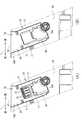
以下、図9を参照して、トナーコンテナ50が装着されるときに、取付部43にトナーコンテナ50の側面54A側のメモリーホルダー60が取り付けられる取付動作について説明する。ここで、図9(A)は、カバー77が前記被覆位置にあり、メモリーホルダー60がまだ取り付けられていない状態を示す。この状態で、メモリーホルダー60は、ホルダー本体61が突出部55の内部に部分的に没入して側面54Aに最も接近する第1姿勢の状態にある。この状態からトナーコンテナ50が更に装着方向(図9の下方向)へ挿入されると、まず、メモリーホルダー60の傾斜面68Aが収容部80の上端80Aに当接する(図9(B)参照)。これにより、傾斜面68Aは、上端80Aから離間する方向(図9の右方向)の力を受ける。この力は、傾斜面68Aよりも上方に位置する回動軸63を中心にメモリーホルダー60を第2姿勢へ向けて回動させるように作用する。このため、図9(B)に示されるように、メモリーホルダー60は、接続端子65が接続端子73側に引き寄せられる。 Hereinafter, with reference to FIG. 9, an attachment operation in which the
トナーコンテナ50が前記装着方向へ更に挿入されると、続いて、係合片67がカバーの傾斜面77Aに当接して係合する(図9(C)参照)。このとき、傾斜面77Aは、係合片67から装着方向の力(下向きの力)を受ける。上述したように、カバー77は前記被覆位置に配置されている。そのため、下向きの力を受けることにより、カバー77は前記露出位置まで移動する。そして、前記露出位置まで移動したカバー77は、その下端がストッパー81によって支持される(図9(D)参照)。 When the
カバー77が前記露出位置にある状態で、トナーコンテナ50が前記装着方向へ更に挿入されると、傾斜面77Aは、係合片67から受ける装着方向の力(下向きの力)を水平方向の力に変換して、ホルダー本体61を取付部43側に引き寄せる。つまり、回動軸63を中心にしてメモリーホルダー60が回動し、第1姿勢から第2姿勢側へ向かう。これにより、接続端子65が接続端子73の接触部73Aに当接する(図9(D)参照)。そして、更にトナーコンテナ50が前記装着方向へ挿入されて、メモリーホルダー60が第2姿勢まで回動すると、接続端子65は、メモリーホルダー60の回動に伴い接続端子73を押圧して収縮させる。また、メモリーホルダー60が第2姿勢まで回動すると、係合片67は、傾斜面77Aを下り降りて、カバー77の上端の平坦部に到達する。これにより、傾斜面77Aと係合片67とによってメモリーホルダー60が第2姿勢に保持される。このように、メモリーホルダー60が第2姿勢に配置されると、接続端子65は接続端子73との間で接続端子73を収縮させた分の弾性力によって互いに接触される。なお、メモリーホルダー60が第2姿勢に配置されたときの接続端子65の位置が本発明の設定位置に相当する。 When the
上述した実施形態に係る画像形成装置10においては、トナーコンテナ50が装着部40に装着されると、メモリーホルダー60が突出部55から引き出されて常に定位置である第2姿勢に配置される。このため、メモリーホルダー60に設けられた接続端子65も常に一定の位置に配置される。したがって、トナーコンテナ50が長手方向に寸法公差を有していても、トナーコンテナ50の接続端子65と装着部40の接続端子73とを確実に安定して電気的に接触させることが可能になる。また、トナーコンテナ50が装着されるときの動作に伴い生じる押圧力によってメモリーホルダー60が突出部55から引き出される構成であるため、モーターなどの駆動力を使用する構成に比べてコストを抑えることができ、構成が簡素化できる。 In the
なお、上述の実施形態では、トナーコンテナ50が装着されていない状態で、メモリーホルダー60が前記第1姿勢及び前記第2姿勢との間を変位自在な構成を例示したが、本発明はこれに限られない。例えば、外力が加えられていない状態で、メモリーホルダー60を側面54Aに近接した前記第1姿勢に保持するために、前記第1姿勢側へメモリーホルダー60を付勢するバネなどの弾性部材を用いてもよい。 In the above-described embodiment, the configuration in which the
また、回動軸63を支点としてメモリーホルダー60を回動する構成としたが、メモリーホルダー60を回動させる構成に限られない。例えば、側面54Aに対して平行を保ったまま側面54Aに垂直な方向へメモリーホルダー60をスライド移動可能な構成を適用することも可能である。 Further, although the
また、上述の実施形態では、メモリーホルダー60を突出部55から引き出す例について説明したが、メモリーホルダー60を設けずに、トナーコンテナ50の側面54Aに接続端子65を設け、更に、側面54Aに傾斜面77Aに係合される被係合部を設け、トナーコンテナ50そのものを引き寄せる構成を適用してもよい。 In the above-described embodiment, the example in which the
また、上述の実施形態では、カバー77が移動可能な構成に例示したが、カバー77は本発明の支持部の一例であって、移動可能に構成されていなくてもよい。少なくとも前記露出位置において側壁75Bに固定されていればよい。もちろん、この場合は、収容部80を設ける必要はない。 In the above-described embodiment, the
また、上述の実施形態では、交換部材としてトナーコンテナ50を例示したが、本発明は、画像形成装置10に対して交換可能な部材であれば適用可能であり、交換部材がトナーコンテナ50に限定されない。例えば、画像形成装置10に対して着脱可能なオプションユニット(ファクスユニット、両面印刷ユニット、スキャナーユニットなど)にも適用可能である。また、現像に使用されなかったトナーを回収する廃トナーボトルなどに装着にも適用可能である。また、給紙装置25や定着装置26が着脱可能に構成されている場合は、これらの装置の装着にも適用可能である。 In the above-described embodiment, the
10:画像形成装置
21:画像読取部
40:装着部
50:トナーコンテナ
55:突出部
59:供給口
60:メモリーホルダー
63:回動軸
65:接続端子
73:接続端子
77:カバー
77A:傾斜面
80:収容部10: image forming apparatus 21: image reading unit 40: mounting unit 50: toner container 55: protrusion 59: supply port 60: memory holder 63: rotating shaft 65: connection terminal 73: connection terminal 77: cover 77A: inclined surface 80: accommodating part
Claims (5)
Translated fromJapanese前記装着部に着脱可能に支持される交換部材と、を備え、
前記交換部材は、
前記装着部に対する前記交換部材の着脱方向に直交する第1方向の一方側の側面に設けられ、接触されることにより電気的に導通可能な第1接触部を有し、
前記装着部は、
前記第1接触部と接触して電気的に接続される第2接触部と、
前記交換部材が前記装着部に装着される装着動作に伴い前記交換部材に係合して前記第1接触部が前記第2接触部に接触する予め定められた設定位置に前記第1接触部を移動させる支持部と、を有し、
前記交換部材は、前記交換部材の前記側面に取り付けられ、前記支持部によって係合される被係合部が設けられ、前記第1接触部を保持する保持部を有し、前記保持部は、前記交換部材の前記側面に対して接離する方向へ移動可能に支持されており、
前記装着部の前記支持部は、前記装着動作時に前記被係合部に当接して前記第1接触部を前記第2接触部へ引き寄せる力を前記保持部に付与する傾斜部を有し、前記保持部を前記側面から離間させることにより前記第1接触部を前記第2接触部へ引き寄せて前記設定位置に移動させる画像形成装置。A mounting portion provided in the apparatus body;
An exchange member that is detachably supported by the mounting portion,
The replacement member is
A first contact portion that is provided on one side surface in a first direction orthogonal to the attaching / detaching direction of the replacement member with respect to the mounting portion and is electrically conductive by being contacted;
The mounting part is
A second contact portion in contact with and electrically connected to the first contact portion;
The first contact portion is placed at a predetermined setting position where the first contact portion comes into contact with the second contact portion by engaging the replacement member with the mounting operation of mounting the replacement member on the mounting portion. a support portion for moving the,was closed,
The replacement member is attached to the side surface of the replacement member, is provided with an engaged portion that is engaged by the support portion, and has a holding portion that holds the first contact portion, It is supported so as to be movable in the direction of contact with and away from the side surface of the replacement member,
The support portion of the mounting portion includes an inclined portion that abuts the engaged portion during the mounting operation and applies a force to the holding portion to pull the first contact portion toward the second contact portion, the image forming apparatus Beforemoving to the set position of the first contact portion by separating the holder from the side attracts to the second contact portion.
前記装着部に着脱可能に支持される交換部材と、を備え、
前記交換部材は、
前記装着部に対する前記交換部材の着脱方向に直交する第1方向の一方側の側面に設けられ、接触されることにより電気的に導通可能な第1接触部を有し、
前記装着部は、
前記第1接触部と接触して電気的に接続される第2接触部と、
前記交換部材が前記装着部に装着される装着動作に伴い前記交換部材に係合して前記第1接触部が前記第2接触部に接触する予め定められた設定位置に前記第1接触部を移動させる支持部と、を有し、
前記支持部は、前記第2接触部を覆う第1位置と前記第1位置から一方向へ移動して前記第2接触部を露出させる第2位置との間で移動可能に支持されており、前記装着動作時に前記交換部材から前記着脱方向の力を受けて前記第1位置から前記第2位置に移動し、前記第2位置で前記交換部材を前記設定位置に移動させる画像形成装置。A mounting portion provided in the apparatus body;
An exchange member that is detachably supported by the mounting portion,
The replacement member is
A first contact portion that is provided on one side surface in a first direction orthogonal to the attaching / detaching direction of the replacement member with respect to the mounting portion and is electrically conductive by being contacted;
The mounting part is
A second contact portion in contact with and electrically connected to the first contact portion;
The first contact portion is placed at a predetermined setting position where the first contact portion comes into contact with the second contact portion by engaging the replacement member with the mounting operation of mounting the replacement member on the mounting portion. A support part to be moved,
The support portion is supported movably between a first position that covers the second contact portion and a second position that moves in one direction from the first position to expose the second contact portion, the mounting under the force of the detachable direction from said exchange member to move to said second position from said first position during operation, the second position inimages forming deviceBefore moving the replacement member to the set position.
前記第1接触部は、前記トナー容器に収容されたトナーに関する情報を記憶する記憶部の接続端子である請求項1から3のいずれかに記載の画像形成装置。The replacement member is a toner container configured to be able to store toner therein, and provided with a supply port for supplying the toner to the outside.
It said first contact portion, the image forming apparatus according to any one of claims1-3 which is a connection terminal of the storage unit for storing information about the toner contained in the toner container.
Priority Applications (3)
| Application Number | Priority Date | Filing Date | Title |
|---|---|---|---|
| JP2014011489AJP6091439B2 (en) | 2014-01-24 | 2014-01-24 | Image forming apparatus |
| CN201510030132.3ACN104808468B (en) | 2014-01-24 | 2015-01-21 | image forming apparatus |
| US14/603,240US9229425B2 (en) | 2014-01-24 | 2015-01-22 | Image forming apparatus with detachable replacement member |
Applications Claiming Priority (1)
| Application Number | Priority Date | Filing Date | Title |
|---|---|---|---|
| JP2014011489AJP6091439B2 (en) | 2014-01-24 | 2014-01-24 | Image forming apparatus |
Publications (2)
| Publication Number | Publication Date |
|---|---|
| JP2015138246A JP2015138246A (en) | 2015-07-30 |
| JP6091439B2true JP6091439B2 (en) | 2017-03-08 |
Family
ID=53678954
Family Applications (1)
| Application Number | Title | Priority Date | Filing Date |
|---|---|---|---|
| JP2014011489AActiveJP6091439B2 (en) | 2014-01-24 | 2014-01-24 | Image forming apparatus |
Country Status (3)
| Country | Link |
|---|---|
| US (1) | US9229425B2 (en) |
| JP (1) | JP6091439B2 (en) |
| CN (1) | CN104808468B (en) |
Families Citing this family (19)
| Publication number | Priority date | Publication date | Assignee | Title |
|---|---|---|---|---|
| JP6365462B2 (en)* | 2015-08-17 | 2018-08-01 | 京セラドキュメントソリューションズ株式会社 | Image forming apparatus |
| JP6582972B2 (en) | 2015-12-25 | 2019-10-02 | ブラザー工業株式会社 | Developer cartridge |
| JP6897732B2 (en)* | 2015-12-25 | 2021-07-07 | ブラザー工業株式会社 | Development cartridge |
| JP6589630B2 (en) | 2015-12-25 | 2019-10-16 | ブラザー工業株式会社 | Developer cartridge |
| CN105549361A (en)* | 2015-12-31 | 2016-05-04 | 珠海奔图电子有限公司 | Storage element, developing cartridge using same, and image forming apparatus |
| CN205750283U (en) | 2015-12-31 | 2016-11-30 | 珠海奔图电子有限公司 | Image forming apparatus powder box, Delevoping cartridge and image forming apparatus |
| US10203658B2 (en) | 2016-03-25 | 2019-02-12 | Brother Kogyo Kabushiki Kaisha | Image forming apparatus having electrical contact |
| JP6512177B2 (en)* | 2016-06-08 | 2019-05-15 | 京セラドキュメントソリューションズ株式会社 | Image forming apparatus provided with toner container |
| JP6859647B2 (en)* | 2016-09-30 | 2021-04-14 | ブラザー工業株式会社 | Drum cartridge |
| CN107885057B (en)* | 2016-09-30 | 2022-04-22 | 兄弟工业株式会社 | Developing box |
| JP6897096B2 (en)* | 2016-12-28 | 2021-06-30 | ブラザー工業株式会社 | Image forming device |
| JP2018116091A (en)* | 2017-01-16 | 2018-07-26 | ブラザー工業株式会社 | Development cartridge |
| US10095159B2 (en)* | 2017-01-19 | 2018-10-09 | Kabushiki Kaisha Toshiba | Image forming apparatus and method for acquiring information of toner container |
| JP6930204B2 (en)* | 2017-04-28 | 2021-09-01 | ブラザー工業株式会社 | Image forming device |
| JP6958021B2 (en) | 2017-06-23 | 2021-11-02 | ブラザー工業株式会社 | Development cartridge |
| US10884353B2 (en) | 2019-05-07 | 2021-01-05 | Lexmark International, Inc. | Toner cartridge electrical contacts |
| JP7352597B2 (en)* | 2019-09-05 | 2023-09-28 | ブラザー工業株式会社 | developer cartridge |
| JP7635608B2 (en)* | 2021-03-31 | 2025-02-26 | ブラザー工業株式会社 | Image forming device |
| CN116859697A (en)* | 2023-07-10 | 2023-10-10 | 珠海奔图电子有限公司 | Adapter, box, box set and image forming device |
Family Cites Families (10)
| Publication number | Priority date | Publication date | Assignee | Title |
|---|---|---|---|---|
| JP5000380B2 (en)* | 2007-05-24 | 2012-08-15 | 株式会社リコー | Image forming apparatus and process unit |
| JP4671182B2 (en)* | 2008-10-29 | 2011-04-13 | 富士ゼロックス株式会社 | Image forming apparatus |
| US8577255B2 (en)* | 2008-10-31 | 2013-11-05 | Brother Kogyo Kabushiki Kaisha | Image forming apparatus |
| US20100166466A1 (en)* | 2008-12-31 | 2010-07-01 | Kabushiki Kaisha Toshiba | Toner cartridge and image forming apparatus |
| JP5447938B2 (en)* | 2009-09-01 | 2014-03-19 | 株式会社リコー | Image forming apparatus |
| JP5094823B2 (en)* | 2009-12-02 | 2012-12-12 | 株式会社沖データ | Image forming apparatus |
| KR20120015494A (en)* | 2010-08-12 | 2012-02-22 | 삼성전자주식회사 | Developing cartridge and image forming apparatus including same |
| JP5699634B2 (en)* | 2011-01-28 | 2015-04-15 | ブラザー工業株式会社 | Developer cartridge |
| US8938179B2 (en)* | 2012-06-25 | 2015-01-20 | Lexmark International, Inc. | Toner cartridge for an image forming device having a retainer assembly having positioning features for processing circuitry |
| JP5250139B2 (en)* | 2012-07-06 | 2013-07-31 | 株式会社沖データ | Image forming apparatus |
- 2014
- 2014-01-24JPJP2014011489Apatent/JP6091439B2/enactiveActive
- 2015
- 2015-01-21CNCN201510030132.3Apatent/CN104808468B/enactiveActive
- 2015-01-22USUS14/603,240patent/US9229425B2/enactiveActive
Also Published As
| Publication number | Publication date |
|---|---|
| CN104808468A (en) | 2015-07-29 |
| JP2015138246A (en) | 2015-07-30 |
| CN104808468B (en) | 2019-07-19 |
| US20150212482A1 (en) | 2015-07-30 |
| US9229425B2 (en) | 2016-01-05 |
Similar Documents
| Publication | Publication Date | Title |
|---|---|---|
| JP6091439B2 (en) | Image forming apparatus | |
| RU2643178C2 (en) | Cartridge and device for forming images, in which cartridge is used | |
| US8670690B2 (en) | Process cartridge and image forming apparatus having the same | |
| JP4905157B2 (en) | Image forming apparatus | |
| JP5125172B2 (en) | Image forming apparatus and developing cartridge | |
| KR100690486B1 (en) | Image forming apparatus, unit mountable thereon and separating member | |
| JP4784822B2 (en) | Image forming apparatus | |
| US8380103B2 (en) | Image forming apparatus having photosensitive member unit that moves between an outer position and an operational position | |
| CN102968005B (en) | Image forming apparatus | |
| WO2018225632A1 (en) | Cartridge | |
| JP2016151592A (en) | Cartridge, image forming apparatus, and manufacturing method of cartridge | |
| US7865123B2 (en) | Developing device, waste toner collecting device and image forming apparatus having the same | |
| US9170528B2 (en) | Toner container and image forming apparatus having the same | |
| US20140241736A1 (en) | Image Forming Apparatus Including Cartridge for Protecting Photosensitive Drum | |
| CN106019891A (en) | Powder storage container, developer replenishing device, and image forming apparatus | |
| JP6665828B2 (en) | Image forming apparatus, toner container attachable to image forming apparatus | |
| JP6599766B2 (en) | Consumable container and image forming apparatus including the same | |
| US20140294447A1 (en) | Image forming apparatus | |
| JP2016224149A (en) | Toner container | |
| US11061360B2 (en) | Image forming apparatus | |
| JP7218167B2 (en) | image forming device | |
| US20200310342A1 (en) | Terminal connection structure and image forming apparatus | |
| JP2016206320A (en) | Image forming apparatus | |
| US20250306508A1 (en) | Image forming apparatus | |
| US7555237B1 (en) | Positioning mechanism for positioning a developing apparatus and related developing apparatus |
Legal Events
| Date | Code | Title | Description |
|---|---|---|---|
| A621 | Written request for application examination | Free format text:JAPANESE INTERMEDIATE CODE: A621 Effective date:20151120 | |
| A131 | Notification of reasons for refusal | Free format text:JAPANESE INTERMEDIATE CODE: A131 Effective date:20160823 | |
| A977 | Report on retrieval | Free format text:JAPANESE INTERMEDIATE CODE: A971007 Effective date:20160824 | |
| A521 | Request for written amendment filed | Free format text:JAPANESE INTERMEDIATE CODE: A523 Effective date:20161006 | |
| TRDD | Decision of grant or rejection written | ||
| A01 | Written decision to grant a patent or to grant a registration (utility model) | Free format text:JAPANESE INTERMEDIATE CODE: A01 Effective date:20170110 | |
| A61 | First payment of annual fees (during grant procedure) | Free format text:JAPANESE INTERMEDIATE CODE: A61 Effective date:20170207 | |
| R150 | Certificate of patent or registration of utility model | Ref document number:6091439 Country of ref document:JP Free format text:JAPANESE INTERMEDIATE CODE: R150 |