JP6089284B2 - Stringed instrument, system and method using apparatus similar to stringed instrument - Google Patents
Stringed instrument, system and method using apparatus similar to stringed instrumentDownload PDFInfo
- Publication number
- JP6089284B2 JP6089284B2JP2015120794AJP2015120794AJP6089284B2JP 6089284 B2JP6089284 B2JP 6089284B2JP 2015120794 AJP2015120794 AJP 2015120794AJP 2015120794 AJP2015120794 AJP 2015120794AJP 6089284 B2JP6089284 B2JP 6089284B2
- Authority
- JP
- Japan
- Prior art keywords
- fret
- sensor
- stringed instrument
- neck
- conductive layer
- Prior art date
- Legal status (The legal status is an assumption and is not a legal conclusion. Google has not performed a legal analysis and makes no representation as to the accuracy of the status listed.)
- Expired - Fee Related
Links
- 238000000034methodMethods0.000titleclaimsdescription16
- 230000001939inductive effectEffects0.000claimsdescription11
- 230000004913activationEffects0.000claimsdescription7
- 238000007667floatingMethods0.000claimsdescription7
- 230000000694effectsEffects0.000claimsdescription6
- 230000005057finger movementEffects0.000claimsdescription3
- 238000004519manufacturing processMethods0.000claimsdescription3
- 238000004026adhesive bondingMethods0.000claimsdescription2
- 238000003466weldingMethods0.000claimsdescription2
- 210000003811fingerAnatomy0.000description33
- 230000004044responseEffects0.000description8
- 210000000056organAnatomy0.000description7
- 230000006870functionEffects0.000description6
- 238000003825pressingMethods0.000description6
- 230000008901benefitEffects0.000description4
- 230000008859changeEffects0.000description4
- 238000004891communicationMethods0.000description4
- 239000012212insulatorSubstances0.000description4
- 230000005540biological transmissionEffects0.000description3
- 239000003990capacitorSubstances0.000description3
- 238000012986modificationMethods0.000description3
- 230000004048modificationEffects0.000description3
- 230000008569processEffects0.000description3
- ALDJIKXAHSDLLB-UHFFFAOYSA-N1,2-dichloro-3-(2,5-dichlorophenyl)benzeneChemical compoundClC1=CC=C(Cl)C(C=2C(=C(Cl)C=CC=2)Cl)=C1ALDJIKXAHSDLLB-UHFFFAOYSA-N0.000description2
- 238000006243chemical reactionMethods0.000description2
- 239000011248coating agentSubstances0.000description2
- 238000000576coating methodMethods0.000description2
- 238000010586diagramMethods0.000description2
- 210000004247handAnatomy0.000description2
- 230000006872improvementEffects0.000description2
- 238000000926separation methodMethods0.000description2
- 230000003213activating effectEffects0.000description1
- 238000005452bendingMethods0.000description1
- 238000004590computer programMethods0.000description1
- 238000010276constructionMethods0.000description1
- 230000007423decreaseEffects0.000description1
- 230000003247decreasing effectEffects0.000description1
- 238000001514detection methodMethods0.000description1
- 239000003989dielectric materialSubstances0.000description1
- 238000007599dischargingMethods0.000description1
- 230000005684electric fieldEffects0.000description1
- 210000004932little fingerAnatomy0.000description1
- 239000000463materialSubstances0.000description1
- 238000005192partitionMethods0.000description1
- 239000002574poisonSubstances0.000description1
- 231100000614poisonToxicity0.000description1
- 230000003252repetitive effectEffects0.000description1
- 230000035807sensationEffects0.000description1
- 230000005236sound signalEffects0.000description1
- 239000000758substrateSubstances0.000description1
- 230000002194synthesizing effectEffects0.000description1
- 239000010409thin filmSubstances0.000description1
Images


Classifications
- G—PHYSICS
- G10—MUSICAL INSTRUMENTS; ACOUSTICS
- G10H—ELECTROPHONIC MUSICAL INSTRUMENTS; INSTRUMENTS IN WHICH THE TONES ARE GENERATED BY ELECTROMECHANICAL MEANS OR ELECTRONIC GENERATORS, OR IN WHICH THE TONES ARE SYNTHESISED FROM A DATA STORE
- G10H1/00—Details of electrophonic musical instruments
- G10H1/0008—Associated control or indicating means
- G10H1/0016—Means for indicating which keys, frets or strings are to be actuated, e.g. using lights or leds
- G—PHYSICS
- G10—MUSICAL INSTRUMENTS; ACOUSTICS
- G10H—ELECTROPHONIC MUSICAL INSTRUMENTS; INSTRUMENTS IN WHICH THE TONES ARE GENERATED BY ELECTROMECHANICAL MEANS OR ELECTRONIC GENERATORS, OR IN WHICH THE TONES ARE SYNTHESISED FROM A DATA STORE
- G10H1/00—Details of electrophonic musical instruments
- G10H1/0033—Recording/reproducing or transmission of music for electrophonic musical instruments
- G10H1/0041—Recording/reproducing or transmission of music for electrophonic musical instruments in coded form
- G10H1/0058—Transmission between separate instruments or between individual components of a musical system
- G10H1/0066—Transmission between separate instruments or between individual components of a musical system using a MIDI interface
- G—PHYSICS
- G10—MUSICAL INSTRUMENTS; ACOUSTICS
- G10H—ELECTROPHONIC MUSICAL INSTRUMENTS; INSTRUMENTS IN WHICH THE TONES ARE GENERATED BY ELECTROMECHANICAL MEANS OR ELECTRONIC GENERATORS, OR IN WHICH THE TONES ARE SYNTHESISED FROM A DATA STORE
- G10H1/00—Details of electrophonic musical instruments
- G10H1/32—Constructional details
- G10H1/34—Switch arrangements, e.g. keyboards or mechanical switches specially adapted for electrophonic musical instruments
- G10H1/342—Switch arrangements, e.g. keyboards or mechanical switches specially adapted for electrophonic musical instruments for guitar-like instruments with or without strings and with a neck on which switches or string-fret contacts are used to detect the notes being played
- G—PHYSICS
- G10—MUSICAL INSTRUMENTS; ACOUSTICS
- G10H—ELECTROPHONIC MUSICAL INSTRUMENTS; INSTRUMENTS IN WHICH THE TONES ARE GENERATED BY ELECTROMECHANICAL MEANS OR ELECTRONIC GENERATORS, OR IN WHICH THE TONES ARE SYNTHESISED FROM A DATA STORE
- G10H1/00—Details of electrophonic musical instruments
- G10H1/36—Accompaniment arrangements
- G10H1/38—Chord
- G—PHYSICS
- G10—MUSICAL INSTRUMENTS; ACOUSTICS
- G10H—ELECTROPHONIC MUSICAL INSTRUMENTS; INSTRUMENTS IN WHICH THE TONES ARE GENERATED BY ELECTROMECHANICAL MEANS OR ELECTRONIC GENERATORS, OR IN WHICH THE TONES ARE SYNTHESISED FROM A DATA STORE
- G10H2220/00—Input/output interfacing specifically adapted for electrophonic musical tools or instruments
- G10H2220/155—User input interfaces for electrophonic musical instruments
- G10H2220/265—Key design details; Special characteristics of individual keys of a keyboard; Key-like musical input devices, e.g. finger sensors, pedals, potentiometers, selectors
- G10H2220/275—Switching mechanism or sensor details of individual keys, e.g. details of key contacts, hall effect or piezoelectric sensors used for key position or movement sensing purposes; Mounting thereof
- G10H2220/295—Switch matrix, e.g. contact array common to several keys, the actuated keys being identified by the rows and columns in contact
- G10H2220/301—Fret-like switch array arrangements for guitar necks
- G—PHYSICS
- G10—MUSICAL INSTRUMENTS; ACOUSTICS
- G10H—ELECTROPHONIC MUSICAL INSTRUMENTS; INSTRUMENTS IN WHICH THE TONES ARE GENERATED BY ELECTROMECHANICAL MEANS OR ELECTRONIC GENERATORS, OR IN WHICH THE TONES ARE SYNTHESISED FROM A DATA STORE
- G10H2240/00—Data organisation or data communication aspects, specifically adapted for electrophonic musical tools or instruments
- G10H2240/171—Transmission of musical instrument data, control or status information; Transmission, remote access or control of music data for electrophonic musical instruments
- G10H2240/281—Protocol or standard connector for transmission of analog or digital data to or from an electrophonic musical instrument
- G10H2240/311—MIDI transmission
Landscapes
- Physics & Mathematics (AREA)
- Engineering & Computer Science (AREA)
- Acoustics & Sound (AREA)
- Multimedia (AREA)
- Electrophonic Musical Instruments (AREA)
- Stringed Musical Instruments (AREA)
- Auxiliary Devices For Music (AREA)
Description
Translated fromJapanese本発明は、「ワンマンバンド」(OMB)として用いられる特別に改良された、例えば、ギターといった弦楽器、並びにギタリストが観衆のために独演する又は娯楽として自分のためだけに演奏することを可能にする弦楽器を演奏するシステム及び方法に関する。弦楽器、例えば、ギターは、ギタリストが精通しているコード(和音)及びソロだけでなく、ギタリストの演奏と調和させるための自動伴奏でもって自分自身に伴奏をつけることができるように構成される。この自動伴奏は、ドラム、バス、及びオルガン又はシンセサイザーによって生成される伴奏と同様の、管弦楽組曲及び音楽的な調和を生成できる他の楽器を含む。 The present invention is a specially improved stringed instrument, such as a guitar, used as a “one-man band” (OMB), as well as allowing guitarists to perform alone for the audience or just for themselves as entertainment. The present invention relates to a system and method for playing a stringed instrument. Stringed instruments, such as guitars, are configured to allow accompaniment to themselves with automatic accompaniment to harmonize with the guitarist's performance, as well as chords and solos familiar to the guitarist. This automatic accompaniment includes drums, bass, and other musical instruments that can produce an orchestral suite and musical harmony similar to accompaniments produced by organs or synthesizers.
本発明は、弦楽器の形状又は重量、或いは演奏方法を大幅に又は顕著に変更することなく自動伴奏を実現する。演奏者は、これまで習得したことを放棄する必要はなく、新しい演奏方法を学ぶ必要もなく、ただ自分の知識を少し補うだけである。本発明の1つの利点は、これまでの従来の弦楽器により1人で演奏できる音楽を超えて、音楽を豊かなものにし、ギタリストの演奏が現在知られていない独創的なものになり、豊かな及び高度な音楽を制作することによってギタリストに喜び及び満足を与える可能性が加えられることである。 The present invention realizes automatic accompaniment without significantly or significantly changing the shape or weight of the stringed instrument or the performance method. The performers do not have to give up what they have learned so far, they do not have to learn new ways to perform, they just make up for their knowledge. One advantage of the present invention is that it makes music richer than the music that can be played by one person with conventional stringed instruments, making the guitarist's performance unconventional and rich. And the possibility to give joy and satisfaction to the guitarist by creating advanced music.
従来のアコースティックギター又はエレキギター本体は、様々な形状を有することができるが、主に、サウンドボックス、ネック、フィンガーボード、及び弦から構成される。弦は、サウンドボックス上に取り付けられた「ブリッジ」に取り外し可能に取り付けられ、フィンガーボードの上を通ってネックの端部に張られ、ネックにおいてこれらの弦は各弦に対して1つのチューニングキーに取り付けられ、該チューニングキーは、必要に応じてこれらの弦を調律する又は交換する好都合な方法を提供する。 A conventional acoustic guitar or electric guitar body can have various shapes, but is mainly composed of a sound box, a neck, a fingerboard, and strings. The strings are removably attached to a “bridge” mounted on the sound box and are stretched over the fingerboard to the end of the neck, where the strings are one tuning key for each string. The tuning key provides a convenient way to tune or replace these strings as needed.
弦楽器、例えば、ギターは、改造及び改良の長い歴史があり、最近、MIDI(電子楽器デジタルインタフェース)プロトコルを利用した最新デジタル技術及び電子技術を取り込んで変更されている。 Stringed instruments, such as guitars, have a long history of modifications and improvements, and have recently been modified to incorporate the latest digital and electronic techniques utilizing the MIDI (Electronic Musical Instrument Digital Interface) protocol.
以下の特許は、本発明に関する技術についての現状の典型的なものである。
1)Von Basse他に付与された米国特許第6583632号明細書は、指紋センサとして使用できる作動増幅回路のキャパシタ表面のグリッドを開示する。この特許は、静電容量フレットセンサに関する電子機器だけを定めるものであり、音楽システムは開示していない。
2)Poisonに付与された米国特許第4336734号明細書は、楽音を合成する電子回路を組み込んだギターとして構成された楽器を開示する。タッチセンサー(静電容量)式のフレットセンサが、フレット及び弦の位置に対応する位置に取り付けられる。
3)Leeに付与された米国特許第6753466号明細書は、指の圧力を検出して電子回路をアクティブにする薄膜スイッチコードボードを含む電子的なプログラム可能システムを開示する。プログラム可能なシステムは、プログラムされた音符又はコードをソフトウェアモジュールから読み出し、指の圧力を保持してコードのサウンドを持続する。
4)Danielに付与された米国特許第7541536号明細書は、ギターによって生成された電気的な音声信号を処理するための持ち運び可能なマルチサウンドエフェクトシステムを開示する。タッチセンサー式動的制御ユニットが、ギターの前面パネルに取り付けられる。
5)Kotton他に付与された米国特許第7812244号明細書は、弦楽器に連結され、演奏者の楽器の演奏及び操作を検出するフレットセンサによって収集されたデータから、シンセサイザー及びMIDI制御データを生成して信号を再生するための方法及びシステムを開示する。
6)Sullivanに付与された米国特許第7897866号明細書は、演奏面の選択された位置にあるセンサモジュールを使用して楽器の演奏面上の指の位置を検出するためのシステム及び方法を開示する。センサモジュールは、選択された位置の近くの指によって反射又は拡散される光を発する。
7)Iba他に付与された米国特許第5025703号明細書は、楽器の演奏のための複数のフレットセンサを用いた電子弦楽器を開示する。このフレットセンサは、フィンガーボード上のフレットの動作位置を検出し、楽音の生成を含む様々な制御機能に関してこの情報を使用するための装置を含む。
8)Fala他に付与された米国特許第5033353号明細書は、ギターのフレット上の指使い又はそのような情報を検出する超音波信号を使用して、フレットの検出と音符トリガー機能との間の干渉を最小限にする検出器の改良を開示する。
9)Auten他に付与された米国特許第5990405号明細書は、楽器を演奏し、ステレオスピーカーを含むヘッドマウント3Dディスプレイを着用することによって、コンサートへの参加を模擬して、楽器の実際の演奏と一緒にコンサートの事前に録音された部分を上演できるようにするためのシステムを開示する。
10)Okulovに付与された米国特許第6191350号明細書は、バッテリー電源と共に使用され、事前にプログラムされたコード及び旋律を含むCPU及びメモリを有するようになったギターを開示する。弦の振動は、圧電素子によってピックアップされて増幅される。
11)米国特許第5166467号明細書は、ギターに接続された電子シンセサイザーを操作するフットペダルを開示する。従って、演奏者は、演奏者の手によるギターの演奏及び演奏者の足によるコードの生成を連係して行う必要がある。
12)米国特許第5880393号明細書は、音楽コードを生成するミュージックシーケンサーと共に使用するためのコントローラに関する。この従来技術の特許は、アコーディオンに適用される場合の発明を示して特許請求の範囲とする。この特許において開示されるシステムは、キー操作の楽器に適するが、弦楽器、例えば、ギターには、さほど適用できない。
13)米国特許第7541536号明細書は、増幅されたギターのためのマルチサウンドエフェクトシステムを特許請求の範囲とする。このシステムは、コードの伴奏には適用されない。
14)米国特許出願第2003/0210809Al号明細書は、人間の指を介してキャパシタを放電させることなく人間の指との接触を検出し、これによって人間の指に関する好ましくない感覚を防止するためのセンサにおける改良を開示する。音楽システムについての開示はないので、この特許は、本発明に関連せず、静電容量フレットセンサに関する電子機器を規定するのみである。
15)Kramerに付与された米国特許出願第2003/0210809Al号明細書は、ギター上の指の圧力に関する検知位置情報を提供する静電容量フレットセンサのアレイへの演奏者の指の近接性による、静電容量検知入力に基づいて音楽関連データを生成するための電子システムを開示する。静電容量は、演奏者の指とキャパシタのアレイとの間で測定される。
16)Hacklerに付与されたPCT特許出願第WO95/01632号明細書は、ネック上に配置され、圧力検出装置を手で押すことに応じて制御信号を提供する圧力検出装置を有するエレキギターを開示する。The following patents are typical of the current state of the art relating to the present invention.
1) US Pat. No. 6,583,632 issued to Von Basse et al. Discloses a grid on the capacitor surface of an operational amplifier circuit that can be used as a fingerprint sensor. This patent only defines the electronics for the capacitive fret sensor and does not disclose a music system.
2) U.S. Pat. No. 4,336,734 to Poison discloses a musical instrument configured as a guitar incorporating electronic circuitry for synthesizing musical sounds. A touch sensor (capacitance) type fret sensor is attached at a position corresponding to the position of the fret and the string.
3) US Pat. No. 6,753,466 to Lee discloses an electronic programmable system including a thin film switch code board that detects finger pressure and activates an electronic circuit. A programmable system reads programmed notes or chords from a software module and maintains finger pressure to sustain chord sounds.
4) U.S. Pat. No. 7,541,536 to Daniel discloses a portable multi-sound effects system for processing electrical audio signals generated by a guitar. A touch sensitive dynamic control unit is attached to the front panel of the guitar.
5) U.S. Pat. No. 7,812,244 to Kotton et al. Generates synthesizer and MIDI control data from data collected by a fret sensor connected to a stringed instrument and detecting the performance and operation of the performer's instrument. A method and system for reproducing a signal is disclosed.
6) US Pat. No. 7,879,866 to Sullivan discloses a system and method for detecting the position of a finger on a musical instrument playing surface using a sensor module at a selected position on the playing surface. To do. The sensor module emits light that is reflected or diffused by a finger near the selected location.
7) U.S. Pat. No. 5,025,703 to Iba et al. Discloses an electronic stringed instrument using multiple fret sensors for playing the instrument. The fret sensor includes a device for detecting the operating position of the fret on the fingerboard and using this information for various control functions, including musical tone generation.
8) U.S. Pat. No. 5,033,353 to Fala et al. Uses a fingering on a guitar fret or an ultrasonic signal to detect such information, between fret detection and note trigger function. An improved detector that minimizes interference is disclosed.
9) U.S. Pat. No. 5,990,405, issued to Auten et al., Describes the actual performance of a musical instrument by simulating participation in a concert by playing a musical instrument and wearing a head-mounted 3D display including stereo speakers. Discloses a system for allowing pre-recorded parts of a concert to be performed together.
10) U.S. Pat. No. 6,191,350 to Okulov discloses a guitar used with a battery power source and having a CPU and memory containing pre-programmed chords and melodies. The vibration of the string is picked up and amplified by the piezoelectric element.
11) US Pat. No. 5,166,467 discloses a foot pedal for operating an electronic synthesizer connected to a guitar. Therefore, the performer needs to perform the performance of the guitar by the performer's hand and the chord generation by the performer's feet.
12) U.S. Pat. No. 5,880,393 relates to a controller for use with a music sequencer for generating music codes. This prior art patent claims the invention when applied to an accordion. The system disclosed in this patent is suitable for key-operated instruments, but is not very applicable to stringed instruments such as guitars.
13) US Pat. No. 7,541,536 claims a multi-sound effects system for an amplified guitar. This system does not apply to chord accompaniment.
14) US 2003/0210809 A1 detects contact with a human finger without discharging the capacitor via the human finger, thereby preventing unpleasant sensations on the human finger An improvement in the sensor is disclosed. Since there is no disclosure about the music system, this patent is not relevant to the present invention and only defines the electronics for the capacitive fret sensor.
15) U.S. Patent Application No. 2003/0210809 Al granted to Kramer is based on the proximity of a player's finger to an array of capacitive fret sensors that provide sensed position information regarding finger pressure on the guitar, An electronic system for generating music related data based on capacitance sensing inputs is disclosed. The capacitance is measured between the performer's finger and the array of capacitors.
16) PCT patent application WO 95/01632 to Hackler discloses an electric guitar having a pressure sensing device that is placed on the neck and provides a control signal in response to pushing the pressure sensing device by hand. To do.
本発明は、ギタリストによって演奏されたコードによるコンピュータ化された独創的なコード生成システムをギタリストに提供する。これによって、ギタリストは、通常、(右利きの場合)ギタリストの右手で旋律を演奏し、ギタリストの左手の指の位置を押す及び変更することによって伴奏をつけるコードを生成する。この演奏の出力は、そのまま増幅される。コードを生成する左手の動きは、電子的に取り込まれ、このようにして生成される信号は、音楽制作出力システムに送信される。 The present invention provides guitarists with a computerized and original chord generation system with chords played by guitarists. Thereby, the guitarist usually plays a melody with the guitarist's right hand (if right-handed) and generates a chord that accompanies by pressing and changing the position of the finger of the left hand of the guitarist. The output of this performance is amplified as it is. The left hand movement that generates the chord is captured electronically and the signal thus generated is transmitted to the music production output system.
従って、本発明により、電気的な弦楽器の全体的な外観、感触、又は関連する重量、或いは精通した演奏方法に影響を与えることなく、原音及び演奏方法を維持する電気的な弦楽器、例えば、ギターが提供される。 Thus, according to the present invention, an electric stringed instrument, such as a guitar, that maintains the original sound and method of playing without affecting the overall appearance, feel, or associated weight of the electric stringed instrument, or a familiar playing method. Is provided.
本発明の別の目的は、ユーザインタフェースを介してコンピュータと通信する電気的な弦楽器、例えば、ギターを提供することである。このユーザインタフェースは、フットペダル、タッチスクリーン、キーボード、又はそれらの任意の組み合わせとすることができる。しかしながら、フットペダルは、一般的に、弦をつま弾く又ははじくために自由である必要がある演奏する手の使用を必要としないので好適である。 Another object of the present invention is to provide an electric stringed instrument, such as a guitar, that communicates with a computer via a user interface. The user interface can be a foot pedal, a touch screen, a keyboard, or any combination thereof. However, foot pedals are preferred because they generally do not require the use of a playing hand that needs to be free to pinch or repel strings.
従って、サウンドホールを有する本体と、該本体から延びるネックと、該ネック及びサウンドホールの上に取り付けられる複数の弦と、ネックに沿って弦の下に取り付けられる複数のセンサと、該センサと関連する電子回路とを備え、センサは動的な個別のフレット作動センサを含み、それらの各々は複数の弦の1つの下に対応して配置され、コードが弦楽器の弦で演奏される際に、弦に加えられた指の圧力が対応する動的な個別のフレット作動センサをアクティブにし、演奏されたコードを示す圧力データを電子回路を介してプロセッサに送信して演奏されたコードを含むオーディオ出力を生成する電気的な弦楽器を提供することが、本発明の主な目的である。 Accordingly, a body having a sound hole, a neck extending from the body, a plurality of strings attached over the neck and the sound hole, a plurality of sensors attached along the neck and under the strings, and associated with the sensor And a sensor comprising dynamic individual fret actuation sensors, each of which is disposed correspondingly under one of the plurality of strings and when the chord is played on the string of the stringed instrument. Audio output containing played chords by activating the dynamic individual fret actuation sensor corresponding to the finger pressure applied to the string and sending the pressure data indicating the played chord to the processor via an electronic circuit It is a main object of the present invention to provide an electric stringed instrument that produces
動的な個別のフレット作動センサは、ネック上に、弦の下に配置される。これらのセンサは、静電容量センサであることが好ましいが、誘導センサもまた使用できる。これらの詳細な構造は、以下に説明される。 A dynamic individual fret actuation sensor is placed on the neck, below the string. These sensors are preferably capacitive sensors, although inductive sensors can also be used. These detailed structures are described below.
動的な個別のフレットは、溶着又は接着することによって動的な個別のフレット作動センサ上に取り付けられる。指が弦を押さえる又はつま弾くときに、動的な個別のフレットには圧力が加えられ、これによって動的な個別のフレット作動センサがアクティブになる。このセンサは電気的な信号を生成し、該信号がプロセッサに送信されると、処理されて演奏者の指の動きの圧力データ及び関連するパラメータが識別され測定される。このようにして、自動化されたシステムがアクティブになり、ギターのアコースティックサウンドと調和する音楽伴奏として事前にプログラムされたコードが提供される。 The dynamic individual frets are mounted on the dynamic individual fret actuation sensor by welding or gluing. As the finger presses or plucks the strings, pressure is applied to the dynamic individual fret, which activates the dynamic individual fret actuation sensor. The sensor generates an electrical signal that, when transmitted to the processor, is processed to identify and measure the pressure data and associated parameters of the performer's finger movements. In this way, the automated system becomes active and provides pre-programmed chords as musical accompaniment that harmonizes with the acoustic sound of the guitar.
さらに、本発明と同様の概念は、他の楽器に適用することができ、必ずしも弦楽器のみに適用されるものではない。さらに、例えば、弦がないギターは、本発明の構成要素と共に構成され本発明の方法により演奏される場合、「ワンマンバンド」として機能することができる。 Furthermore, the same concept as the present invention can be applied to other musical instruments, and is not necessarily applied only to stringed musical instruments. Further, for example, a guitar without strings can function as a “one man band” when configured with the components of the present invention and played by the method of the present invention.
自動伴奏が作動して、演奏の様々な形態、例えば、コードのスライド又はハッハッ(wha−wha)において普及している特別な効果を残しておく場合に、依然として、ギターの原音が残ることに留意することが重要である。それに加えて、自動伴奏並びに原音を増大又は減少させてそれらを調節して、それらの間の適切なバランスを達成することができる。音楽出力システムは、ケーブル又は無線システムによって電気的な弦楽器に取り付けられたコンピュータで動作する。従って、電気的な弦楽器を通常の方法で使用することを望む人は、それをコンピュータに取り付けるのではなく、オーディオ出力に取り付けるだけでよい。 Note that the original sound of the guitar still remains when the automatic accompaniment is activated to leave a special effect that is prevalent in various forms of performance, such as chord slides or wha-wha. It is important to. In addition, the automatic accompaniment as well as the original sound can be increased or decreased to adjust them to achieve an appropriate balance between them. The music output system operates on a computer attached to an electric stringed instrument by cable or wireless system. Thus, a person who wants to use an electric stringed instrument in the usual way need only attach it to the audio output rather than attach it to a computer.
本発明の別の目的は、弦楽器を演奏する人が一人で、音楽伴奏とともに完全なバンドのように演奏できるように構成されたシステムを提供することである。アナログデジタル変換機能を含む前述のようなフレット作動センサシステムを備える弦楽器と、音楽伴奏をシステムに選択的に取り入れるためのユーザインタフェースと、フレット作動センサシステム及びユーザインタフェースの両方から受信されMIDIプロトコルチャネルによって送信されたデジタル信号を処理するためのMIDIインタフェースと、MIDIプロトコルによって接続されてオーディオ出力を生成するシンセサイザーモジュールとを備え、プロセス全体がコンピュータによって制御されるシステムが提供される。 Another object of the present invention is to provide a system configured so that a single person playing a stringed instrument can perform like a complete band with a musical accompaniment. A stringed instrument with a fret actuation sensor system as described above that includes analog-to-digital conversion functionality, a user interface for selectively incorporating music accompaniment into the system, and a MIDI protocol channel received from both the fret actuation sensor system and the user interface. A system is provided that includes a MIDI interface for processing a transmitted digital signal and a synthesizer module connected by a MIDI protocol to generate an audio output, the entire process being controlled by a computer.
ユーザインタフェースは、ソロ演奏(ワンマンバンド)における使用のためのキーボード又はフットペダルとすることができ、自動伴奏のための入力(例えば、サウンドの変化、分割、置き換え、プログラミング、調和、発音、テンポ、イントロ、エンディング、他)を提供することができる。 The user interface can be a keyboard or foot pedal for use in solo performance (one-man band) and inputs for automatic accompaniment (eg, sound change, split, replacement, programming, harmony, pronunciation, tempo, Intro, ending, etc.).
本発明の電気的な弦楽器、例えば、ギターは、様々なレベルの機能で、オルガンのように使用できるように、様々な構造で製造される。従って、初心者、音楽的な体験を豊かにすることを望むアマチュア、並びにソロ又はグループで出演する高度な演奏者及び職業的な音楽家が使用するように適切に構成されたギターが提供される。或いは、任意の単純なギターを後付けして、それを本発明の方針によるワンマンバンド及びギターに改造することができる。従って、本発明は、全てのギター市場、例えば、エレキギター、クラシックギター、アコースティックギターにおける利用、並びに一般的な弦楽器の同様の種類に適している。 The electric stringed instrument of the present invention, eg, a guitar, is manufactured in a variety of structures so that it can be used like an organ with various levels of functionality. Accordingly, guitars are provided that are suitably configured for use by beginners, amateurs who want to enrich their musical experience, and advanced performers and professional musicians performing in solo or group. Alternatively, any simple guitar can be retrofitted and converted to a one-man band and guitar according to the principles of the present invention. Thus, the present invention is suitable for use in all guitar markets, such as electric guitars, classical guitars, acoustic guitars, and similar types of common stringed instruments.
幾つかのキー及びディスプレイ画面(図示せず)を備え、キーが押された時間及び速度に関して必要な圧力を使用者が調節することができるようなMIDIインタフェースが提供される。例えば、キーが短時間押された場合、ディスプレイ画面は、そのキーから1つの種類の応答を通知し、同じキーを長時間押すと、別の種類の応答が意図されていることをMIDIインタフェース24に通知する。さらに、キーを押す間の様々な間隔(タイミング又は連打)は、音楽的な応答に影響を与える。これらの応答は、事前にプログラムされて具体的な演奏セッションに関して演奏者が望む音楽的な成果の趣向及び選択を反映し、プログラミングにおける柔軟性を高めたものとなっている。 A MIDI interface is provided that includes several keys and a display screen (not shown) so that the user can adjust the required pressure with respect to the time and speed at which the keys are pressed. For example, if a key is pressed for a short time, the display screen will notify one type of response from that key, and pressing the same key for a long time will indicate that another type of response is intended. Notify In addition, various intervals (timing or repetitive strikes) between key presses affect the musical response. These responses are pre-programmed and reflect the taste and choice of musical outcomes desired by the performer for a specific performance session, providing increased programming flexibility.
ほとんどの弦楽器、例えばギターは、一般的に、フレットセクションに分割されギターの全ての弦にわたって延びる固定されたフレットで隔てられたフィンガーボードを備え、本発明においては、動的なフレットが個別の移動可能な区画となっており、互いとは無関係に動作する。本発明の好ましい実施形態において、圧力の変化を識別するためのフレット作動センサが、各動的なフレットの下に配置される。フレットセンサは、約0.6mm又はそれより薄い厚さの非常に薄い構成要素であることを特徴とする。 Most stringed instruments, such as guitars, generally have a fingerboard that is divided into fret sections and separated by fixed frets that extend across all strings of the guitar, and in the present invention, dynamic frets are individually moved. It is a possible partition and operates independently of each other. In a preferred embodiment of the present invention, a fret actuation sensor for identifying pressure changes is placed under each dynamic fret. The fret sensor is characterized by a very thin component having a thickness of about 0.6 mm or less.
典型的なギターのネックの上には、およそ18個のフレットセクションが存在し、フレットの高さ、すなわち、各弦の間の、ネックの端部からブリッジに向けてのテーパーは、ギターの種類及びその製造元によって決まる。例えば、ギターが6本の弦及び18個のフレットセクションを有する場合には、およそ108(18×6)個のフレットセンサの位置がある。明らかに、それらの全てを同時に押さえることはできない。本発明は、この問題を的確に解決する。 There are approximately 18 fret sections above a typical guitar neck, and the height of the fret, ie the taper from the end of the neck to the bridge, between each string is the guitar type. And its manufacturer. For example, if the guitar has 6 strings and 18 fret sections, there are approximately 108 (18 × 6) fret sensor positions. Obviously, you can't hold them all at the same time. The present invention accurately solves this problem.
各フレットの間隔に1つのフレットセンサが必要とされない。必要とされるフレットセンサの総計を半分に削減した9個のフレットセクションに、本発明によって提供されるようなフレットセンサを配置することで十分である。 One fret sensor is not required for each fret spacing. It is sufficient to place the fret sensors as provided by the present invention in nine fret sections, which reduces the total number of fret sensors required by half.
人差し指でフレットの間隔の全ての弦を押さえ、3本の指(中指、薬指、及び小指)で別のフレットの間隔の弦を押さえるコード(完全なコード)がある。この状況では、各弦は、1箇所より多い箇所に対して演奏者の指で押さえられる(同じフレットの間隔に対してではない)。 There is a chord (complete chord) that holds all the strings in the fret interval with the index finger and holds the strings in another fret interval with three fingers (middle finger, ring finger, and little finger). In this situation, each string is pressed by the performer's finger against more than one place (not against the same fret spacing).
指の圧力及び他の関連するデータを識別するのに利用可能な幾つかの公知の技術がある。これらの中には、誘導及び静電容量方式がある。フレット作動センサの具体的な構成及び配置及び使用方法は、本発明の本質をなす。両方の方式は、動的なフレットの下に取り付けられるフレット作動センサと共に動作し、アクティブになると、それらの電気的な特性に変化をもたらすことができる。 There are several known techniques that can be used to identify finger pressure and other related data. Among these are inductive and capacitive methods. The specific construction and arrangement and use of the fret actuation sensor form the essence of the present invention. Both schemes work with fret actuation sensors mounted under dynamic frets and can change their electrical characteristics when activated.
フレットセクションの近くに配置される瞬間的な動的なフレット32の僅かな機械的な動作による音響特性の顕著な差異はほとんどないので、フレット作動センサの導入より、それらが演奏者の手の自由さを妨げることはなく、弦楽器、例えば、ギターの原音とほとんど又は全く干渉しないようになっている。 Since there is little noticeable difference in acoustic properties due to the slight mechanical movement of the instantaneous dynamic fret 32 located near the fret section, they are more free to the player's hands than the introduction of fret actuation sensors. It does not interfere with this, and has little or no interference with the original sound of a stringed instrument such as a guitar.
本発明の好ましい実施形態において、プロセッサ(図示せず)は、互いにMIDI通信チャネルを介して接続されるが、被覆線又は撚り線と共にTTLレベルのUARTを使用してMIDIインタフェース24に接続することができる。 In a preferred embodiment of the present invention, the processors (not shown) are connected to each other via MIDI communication channels, but may be connected to the
演奏者の指の圧力を識別するための2つの実現手段、すなわち、動的なフレットへの演奏者の指の直接的な接触、又は動的なフレットに対する弦の押さえがある。これらを検出することにより、演奏者によって加えられた圧力を識別し、どのデータをMIDI通信チャネルを介して送信するかを判断することが可能となる。2つの実現手段があるので、フレットセンサは、圧力データだけでなく、指の位置、及び適切な信号をシステムに伝えて所望の応答を得るために必要とされる場合がある他の関連するパラメータを識別する必要がある。 There are two realizations for identifying the player's finger pressure: direct contact of the player's finger to the dynamic fret, or string hold on the dynamic fret. By detecting these, it is possible to identify the pressure applied by the performer and determine which data to send over the MIDI communication channel. Since there are two implementations, the fret sensor is not only pressure data, but also the finger position and other relevant parameters that may be needed to communicate the appropriate signal to the system to obtain the desired response. Need to be identified.
MIDIプロトコルは、各弦に対して2バイトの同時性のヘッダ部を含み、1番目のバイトは、押された動的な個別のフレットを識別し、2番目のバイトは、圧力に関する追加的な情報を与える。最後には、バイトのチェックサムがある。このMIDIプロトコルには、毎秒115200バイトの速度の通信が必要とされる。 The MIDI protocol includes a 2-byte simultaneity header for each string, the first byte identifies the dynamic individual fret that was pressed, and the second byte is an additional pressure related Give information. Finally, there is a byte checksum. This MIDI protocol requires communication at a rate of 115200 bytes per second.
本発明の他の機能及び利点は、図面及び以下の説明から明らかになる。 Other features and advantages of the present invention will become apparent from the drawings and the following description.
本発明の実施形態に関して本発明をよく理解するために添付図面を参照する。 For a better understanding of the present invention with respect to embodiments thereof, reference is made to the accompanying drawings.
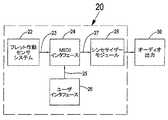
図1を参照すると、本発明の電気的な弦楽器の電子システムの好ましい実施形態のブロック図が示される。システム20は、全体として、4つの構成要素、すなわち、アナログデジタル変換機能を含む動的な個別のフレット作動センサシステム22と、音楽伴奏に関する入力をシステム20に選択的に導入するためのユーザインタフェース26と、ケーブルを介して又は無線伝送によってチャネル23、25を経由して、当業者にとって公知のMIDIプロトコルによって送信され、動的な個別のフレット作動センサシステム22及びユーザインタフェース26の両方から受信されるデジタル信号を処理するためのMIDIインタフェース24と、MIDIプロトコルによって接続されてオーディオ出力30を生成するシンセサイザーモジュール28とを備える。 Referring to FIG. 1, a block diagram of a preferred embodiment of the electrical stringed electronic system of the present invention is shown.
フレット作動センサシステム22内の、又は代替的にMIDIインタフェース24自体内のいずれかの少なくとも1つのプロセッサは(図示せず)、アナログ圧力データを前述のようにシステム20の各構成要素の間で共有されるMIDI通信チャネルによって送信することが容易なデジタルデータに変換する。 At least one processor (not shown) either in the fret
フレット作動センサシステム22は、弦楽器、例えば、ギター(図2A、2B)の複数の弦38上の演奏者の指の圧力、並びにこのような圧力の位置及び継続時間を識別するために使用される。 The fret
ユーザインタフェース26の使用は、本発明の好ましい実施形態である。本発明によるユーザインタフェース26は、演奏者が電子システムと対話できるようにするキーボードコンソール又はタッチスクリーン上のプログラム可能な有効化キーの配列(図示せず)を含む。或いは、フットペダルは(図示せず)、電子システムに関するスイッチを足で作動させるために使用され、ギター演奏者の手及び指が自由に使えるようにする。キー又はフットペダルの圧力は、MIDIチャネル25を介してMIDIインタフェース24(図1)に送信される。或いは、ユーザインタフェース26は、一般的なオルガン、PCに接続されるタッチスクリーン、又はキーボードさえも含むことができるが、フットペダルを含むこと又は含まないこともある。音楽伴奏は、様々な種類の楽器のものとすることができ、弦楽器からのものだけではない。これらは、ギターのアコースティックサウンドと調和させるために事前に録音されるか、又はデジタル形式でPCからダウンロードすることができ、これはシステム20の動的な個別のフレット作動センサシステムに適応している。 The use of
MIDIインタフェース24は、フレット作動センサシステム20からMIDIプロトコル伝送チャネル23を介して、及びユーザインタフェース26からMIDIプロトコル伝送チャネル25を介してそれぞれ受信されるデジタル信号を処理し、このデータは、別のMIDIプロトコルチャネル27を介してシンセサイザーモジュール28に供給されて更に処理され、オーディオ出力30に送信される。オーディオ出力30は、弦楽器(図2Aを参照)の演奏から、又は演奏者が弦楽器ソロの演奏時にユーザインタフェース26の操作によって選択的に導入した音楽伴奏から生成されるサウンドを含む、音楽音響の任意の組み合わせとすることができる。シンセサイザーモジュール28は、様々な楽器の合成されたコードを追加して、バンド全体の演奏のオーディオ出力30に効果を与え、実質的にワンマンバンドにする。MIDIインタフェース24は、コードが押さえられたか否か又は加圧時間の長さが有効か否かを識別することを含む、事前に定義された演奏者の指の圧力の生の情報を受信する。圧力情報は、これらの基準の両方を満たしている場合にはMIDIチャネル23を介してMIDIインタフェース24に送信されることになる。 The
MIDIインタフェース24は、ギターに供給される外部電力と(図示せず)、少なくとも1つのプロセッサとを備え、該プロセッサは、ギターから情報を受信してMIDIでコードを識別し、同時に、ユーザインタフェース26、例えば、フットペダル、キー、又はタッチスクリーンからMIDI情報を受信し、ギターのアコースティックサウンドをユーザインタフェース26からの音楽伴奏と組み合わせるが、これらの情報は、MIDIインタフェース24で処理され、シンセサイザーモジュール28に送信されてオーディオ出力30を生成する。 The
シンセサイザーモジュール28は、当業者には公知のような、電子シンセサイザー、MIDI入力対応オルガン、コンピュータプログラム、コンピュータ処理ユニット(CPU)の一部としてのMIDIモジュール、又はMIDIプロトコルに対応する他のミュージックシーケンサーとすることができる。 The
シンセサイザーモジュール28は、演奏される弦楽器のアコースティックサウンド、及び音楽家−演奏者がユーザインタフェース26を操作することによる、システム20への選択された音楽伴奏入力を含むデジタル信号を、MIDIプロトコルチャネル27を介してMIDIインタフェース24から受信する。シンセサイザーモジュール28は、弦楽器からのサウンドを音楽伴奏と統合して処理し、(矢印の)オーディオ出力30を生成するようにプログラム可能である。 The
シンセサイザーモジュール28は、キーボード上の作動されたキーから、フットペダルから、又はギターのネック34(図2Aを参照)のフレット作動センサ(図2Cの要素42、又は図3Bの要素56を参照)から演奏者の指示に応じたサウンドを生成する。 The
いくつかの利用可能な既製の製品を使用することができるが、ハードウェア及びソフトウェアを統合し、シンセサイザーモジュール28として機能して、システムの全ての構成要素からの情報を取りまとめるPCを得ることが望ましい。本発明に関して、基本的なコンピュータのみが必要とされ、高機能なコンピュータは必要とされず、当業者に公知のMIDI及び高音質のオーディオアダプタのみが必要であり、インターネット上の情報源を参照にすると、本発明と共に使用するのに適した既製の構成要素が容易に分かるはずである。 Although several available off-the-shelf products can be used, it is desirable to obtain a PC that integrates hardware and software and functions as a
ディスプレイ画面がユーザ入力及びシンセサイザーモジュール28のプログラミングに使用される場合には「タッチ」スクリーンが好ましく、経済性及びユーザ操作性のために調節可能なスタンド上の小型スクリーンが好ましい。PC又はこの機能のために特別に設計された構成要素は、当業者には公知のように、スタンドの底部に配置することができる。さらに、演奏機器の基部の周りにペダル用の固定装置を備えることが推奨される。このユニットは、折り畳み式とすることができ、折り畳むと台車に変化してプラットホーム又はステージ上で好都合に運搬すること又は移動させることができる。 A “touch” screen is preferred when the display screen is used for user input and programming of the
オルガンは(図示せず)、標準的な楽器であり、その幾つかにはMIDI入力がある。MIDIプロトコルは標準的であり、これはギター及びペダルがオルガンのインタフェースの一部となるようにオルガンに接続することができる。これらは使用が容易で既知の結果をもたらすという利点がある。これらのサイズ及びプログラミングの柔軟性がないことが欠点である。 The organ (not shown) is a standard instrument, some of which have MIDI inputs. The MIDI protocol is standard and can be connected to the organ so that the guitar and pedal are part of the organ's interface. These have the advantage of being easy to use and giving known results. The disadvantage is their lack of size and programming flexibility.
シンセサイザーモジュール28は、MIDIシステムから音楽を生成するのに必要な全てを含み、使用が容易で既知の結果をもたらす。 The
適切なプログラムを有するコンピュータは、サウンドの制作に必要な最大限の柔軟性を与え、特に、本発明のシステムを作るのに必要な一連のタスクを上手く生成することができる。このシステムの主要な利点は、プログラミングにおいて最大限の柔軟性が可能になる点である。 A computer with the appropriate program gives the maximum flexibility necessary for sound production and, in particular, can successfully generate a series of tasks necessary to create the system of the present invention. The main advantage of this system is that it allows maximum flexibility in programming.
サウンドを制作する能力は、当業者には公知のように、単に選択されたシンセサイザーモジュール28に依存する。実際には、音楽の実現は、選択されたシンセサイザーのある種の演奏内容、並びにシンセサイザーによって提供されるサウンド及びその演奏内容に関するレベル及び選択によって制限される。 The ability to produce sound depends solely on the
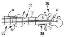
図2A及び2Bでは、それぞれ、本発明の好ましい実施形態に適合するギターのネック34の一部に関する全体的な平面図、及び概略的な拡大図が示されている。 In FIGS. 2A and 2B, there are shown a general plan view and a schematic enlarged view, respectively, of a portion of a
例示的に、ギターのネックの長さ方向に沿って張った6本の弦38を有する典型的なギターのネック34の一部が示されている。幾つかの弦楽器の弦は、これより少ないか又は多いものとすることができる。複数の弦38の各々の下には、対応する複数の動的な個別のフレット32a−l(図2Bを参照)が示されている。図2C、2D、及び2Eから良く分かるように、動的な個別のフレット32及び動的な個別のセンサ42の構造及び動作が例示的に示されている。 Illustratively, a portion of a
ここで図2Aを詳細に参照すると、例示的に、本発明の好ましい実施形態における本発明の原理による改良されたギターのネック34の一部の全体的な平面図が示されている。 Referring now in detail to FIG. 2A, there is illustratively shown a general plan view of a portion of an
ネック34は、典型的なギターに見られるようなネック34の幅にわたって列を成して配列された動的な個別のフレット作動センサ32によって、フレットセクション33に分割される。通常6本又はそれより多い弦38は、下側のボディ部(図示せず)からヘッド36にピンと張られ、該ヘッド36において、これらの弦38は、弦38の張力を調節する又は必要に応じて弦38を取り換えるために使用されるチューニングペグ37のセットに取り外し可能に留められる。 The
図2Bは、図2Aの細部Aの概略的な拡大図であり、本発明の好ましい実施形態によるギターの弦の下に配置される動的な個別のフレット32aから32lの2つの列の平面図を示す。 FIG. 2B is a schematic enlarged view of detail A of FIG. 2A, and a plan view of two rows of dynamic individual frets 32a to 32l disposed under a guitar string according to a preferred embodiment of the present invention. Indicates.
演奏者の指の圧力及び他の関連データを検出し識別するためのフレットセンサシステム22(図1を参照)は、ネック34に取り付けられる。動的な個別のフレット作動センサ42(図2Cを参照)によって収集されるデータは、アナログ又はデジタル形式でMIDIインタフェース26(図1を参照)に送信されて処理される。弦38の押さえ又はつま弾きは、対応する弦38の下にある個別のフレット作動センサ42によって即座に特定可能である。ギターの弦38は、非導電性となっており、フレットセンサシステム22(図1を参照)の電子機器との競合を防止する。特定の動的な個別のフレット32を押すと、対応する個別のフレット作動センサ42がアクティブになる。演奏者は、選択されたコード及び音楽伴奏を呼び出して、ギターのアコースティックサウンドと調和させるために使用されるユーザインタフェース26によって出力を強化する。 A fret sensor system 22 (see FIG. 1) for detecting and identifying the player's finger pressure and other related data is attached to the
フレット作動センサシステム22(図1)は最小の形状であり演奏を妨害しないように設計される。1つのみではなくそれより以上のフレットセクション33に分散するコードがあるので、フレットセクション33の動的な個別のフレット32の間の接続は高速直線チャネルである。押さえられたコードの再現は、関連するフレットセクション33の各々の動的な個別のフレット作動センサ42から情報を収集するように動作し、複数の弦38上の演奏者の指の動き及び圧力を識別して特定のコードを生成する別個のプロセッサ(図示せず)によって最良に実現できることを理解されたい。 The fret actuation sensor system 22 (FIG. 1) is designed to be minimal in shape and not interfere with performance. The connection between the dynamic individual fret 32 of the
細部Aは、その間にフレットセクション33が形成される個別のフレット32aから32f及びフレット32gから32lの2つの隣接する列を示し、ここでは演奏者は弦38をはじくこと又はつま弾くことができる。個々の、動的な個別のフレット32aから32lの下には、動的な個別のフレット作動センサ42(図2Cを参照)がある。或いは、動的な個別のフレットセンサ56(図3Bを参照)は、演奏者の指の動き及び指の圧力の強弱の変化を検出し識別して、事前にプログラムされた又は選択されたコードを呼び出して、ギター自体からのアコースティックサウンドに伴奏をつけることができる。 Detail A shows two adjacent rows of individual frets 32a to 32f and frets 32g to 32l between which the
断面P−P(図2Cを参照)に関して以下に更なる詳細を示して説明する。 The cross-section PP (see FIG. 2C) will be described in further detail below.
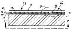
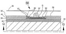
図2C、2D、及び2Eは、縮尺通りではないがネック部34を示し、該ネック部34はPCB(プリント回路板)44を備え、該PCB(プリント回路板)44上に複数の動的な個別のフレット作動センサ42が取り付けられ、該動的な個別のフレット作動センサ42の各々は、非常に薄い上側導電層48aから絶縁体の層52で隔てられた非常に薄い下側導電層50を備え、作動する個別のフレット32は上側導電層48aに取り付けられ、静電容量式のフレット作動センサ42を構成する。 2C, 2D, and 2E show a
ここで図2Cを参照すると、図2BのP−Pの断面図が示され、本発明の好ましい実施形態によるギターのネック34上に取り付けられた個別のフレット作動フレットセンサ42の配置が示される。PCB44は、標準的なフレットボード(図示せず)の代わりにネック34に取り付けられ、動的な個別のフレット32の下に配置され取り付けられる複数の個別の屈曲式フレット作動センサ42と共に構成される。上側導電層48aの僅かな部分48aのみが実際に屈曲する。上側導電層48bの大部分は、上側導電層48a/bと下側導電層50とを隔てる絶縁体46に固定して取り付けられる。 Referring now to FIG. 2C, a cross-sectional view of PP of FIG. 2B is shown, showing the arrangement of individual fret actuation fret
細部Bに関する更なる詳細を、図2Dに拡大した図で示す。 Further details regarding detail B are shown in an enlarged view in FIG. 2D.
図2Dは、図2Cの細部Bを拡大した図であり、本発明の一実施形態の典型的な個別のフレットセンサ42における上側及び下側導電層50及び48aそれぞれの配置の断面図を示す。独立した動的なフレット32が示されており、フレットセンサ42の上側導電層48aに取り付けられている。上側導電層48a及び下側の固定された層50の対向面には、絶縁体の非常に薄いコーティング52が被覆されていることに留意されたい。隙間Gは、L字形状の空隙として示されているが、上側の屈曲可能な導電層48aと下側の固定された層50との間で僅かな離隔を保つように、適切な圧縮性の誘電材料を使用して空隙を埋めることができる。上側導電層48aと上側導電層48bとの間の非常に狭い離隔54を保つように、上側導電層48aが上側導電層48bと完全に適合して、全てがPCB44上に取り付けられる、上側導電層48bの一部、絶縁層50、及び下側導電層50を含む固定された材料の層の残りの部分との偶発的な接触を防止する。ギターの弦38は、動的な個別のフレット32(図2Dを参照)の上に張られており、弦38上の指の圧力が結果的に動的な個別のフレット32を押し下げ、これに対応して個別の屈曲式フレットセンサ42(詳細は図2Eを参照)を作動させるようになっている。 2D is an enlarged view of detail B of FIG. 2C, showing a cross-sectional view of the placement of the upper and lower
図2Eは、図2Cの細部Bを拡大した別の図であり、下向きの指の圧力が屈曲式フレットセンサ42に加えられた場合の、屈曲式フレットセンサ42の上側の屈曲導電層48aの屈曲運動を示す。上側導電層48aに取り付けられた動的な個別のフレット32を示す。演奏者の指の圧力(矢印45)が動的な個別のフレット32上で弦38を押さえるときに、動き(矢印47)により、上側導電層48aが、小さい円弧(矢印)47で下側導電層50に向かって10分の数ミリメートル屈曲するので、隙間Gが減少して、上側導電層48と下側導電層50との間の静電容量値が増加する。 FIG. 2E is another enlarged view of detail B of FIG. 2C in which the bent
この静電容量の増加は、幾つかの方法、例えば、周波数の変化の測定、電圧の変化の測定、又は帯電時間の測定でもって測定することができる。動的な個別のフレット作動センサ42の各々は、対応する動的なフレット32に加えられた圧力に応じて静電容量値を変化させる。フレットセクション、フレットセンサ42ごとの静電容量値は、更に処理するためにマイクロプロセッサ(図示せず)に送信される。 This increase in capacitance can be measured in several ways, for example, measuring frequency changes, measuring voltage changes, or measuring charging time. Each dynamic individual fret
前述のマイクロプロセッサの処理機能の1つは、ギターの演奏者が所定の圧力で少なくとも2つのフレットセクション(すなわち、少なくとも2つの音符のコード)を同時に押しているかどうかを認識する機能を含み、この機能は、ギターを演奏することによって生成されるアコースティックサウンドに伴奏をつけるための少なくとも1つの旋律的なコードを呼び出すための信号を形成するのに必要とされる。 One of the processing functions of the aforementioned microprocessor includes the ability to recognize whether a guitar player is simultaneously pressing at least two fret sections (ie, chords of at least two notes) with a predetermined pressure. Is required to form a signal for calling at least one melodic chord to accompany the acoustic sound produced by playing the guitar.
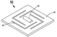
図3A及び3Bは、それぞれ、本発明の典型的なフレットセンサの別の実施形態の斜視図及び平面図を示し、図3C及び図3Dは、図3BのQ−Qを拡大した断面図を示す。センサ56は、「浮動する」上側導電層58上に取り付けられた動的な個別のフレット32を備える。浮動した様子は、上側導電層58の自由な状態の結果であり、上側導電層58は、図2Cに示すように屈曲するのではなく、下側導電層50(図3C、3D)に向かって下向きにほぼ均等に押し下げられる。 3A and 3B show a perspective view and a plan view, respectively, of another embodiment of an exemplary fret sensor of the present invention, and FIGS. 3C and 3D show enlarged cross-sectional views of QQ in FIG. 3B. . The
一連の4個のL字形状の溝部60は、動的なフレット32の周りに幾何学的なパターンでエンボス加工され、上側導電層58に押し下げられた動的なフレット32からの圧力が加えられる場合に、小さな浮動安定性を促進するようになっている。L字形状の溝部60は不要な水平方向の変形を防止するように作用し、上側導電層58から圧力がなくなると溝部60を有する表面が持ち上がり、溝部60は通常位置に戻ることができる。 A series of four L-shaped
図3Cを詳細に参照すると、動的な上側導電層58を備えた浮動式フレットセンサ56、及び誘電体52で隔てられた下側導電層50が示される。浮動式フレットセンサ56は、上側導電層58及び下側導電層50の高さ距離が最大であり、非アクティブな状態で示されている。 Referring to FIG. 3C in detail, a floating fret
図3Dは、図2Eに説明し示した特徴と類似しており、図2Eでは屈曲式フレットセンサ42を有し、図3Dでは浮動式フレットセンサ56を有する点で異なる。1つ又はそれ以上のギターの弦38を押さえることによって動的なフレット32に圧力45(矢印)を加える場合、上側導電層58は、矢印53の動きで示すように下向きに押し込まれる。2つの層58、50との間の距離の変化は、静電容量を引き起こす。この情報は、プロセッサ(図示せず)に送信され、電子システムで処理された後、演奏者が多くの種類の音楽伴奏を選択できるユーザインタフェース26からの入力に応じて、オーディオ出力で調和して聞こえる音楽コードが生成される。 FIG. 3D is similar to the features described and illustrated in FIG. 2E, with the difference that FIG. 2E has a bent fret
非導電性の絶縁体又は誘電体46は、フレットセンサ56の2つのアクティブ層を隔てる。各導電層50、58の対向面には絶縁体のコーティング52が被覆されている。 A non-conductive insulator or dielectric 46 separates the two active layers of the
静電容量の変化が測定され、プロセッサ(図示せず)によってデジタル形式に変換されたデータは、本発明のシステム(図1)における電子制御及び構成のための入力として使用されて、自動化され選択された音楽伴奏を生成してギターで演奏したソロのアコースティック出力と調和させる。 Data measured in capacitance change and converted to digital form by a processor (not shown) is used as an input for electronic control and configuration in the system of the present invention (FIG. 1) for automation and selection. The music accompaniment is generated and harmonized with the acoustic output of the solo played on the guitar.
本発明の好ましい実施形態における屈曲式フレットセンサ42に関して、前述のような静電容量素子を説明したが、随意的に(図4に関して説明するような)インダクタンス素子を使用して前述の発明を実施することができる。 While the capacitive element as described above has been described with respect to the flexure fret
図4は、本発明の別の実施形態によるインダクタンスコイルで構成されるフレットセンサの斜視図である。フレットセンサ70は、2つの電気コイル72a及び72bからのインダクタンス効果を利用して動作する。例示的に、右巻きインダクタンスコイル72aが上側の電極66に組み込まれ、左巻きインダクタンスコイル72bがフレットセンサ70の下側の固定された電極68に組み込まれる。コイル72a/bの間で電界が発生する際に、誘電体の隙間Gが変化する。これらのコイルがPCB又は同様の非導電性の基板44(図3C)上に取り付けられる場合には、コイルの中心から延びる1本の線が入力として動作し、各コイル72a/bの他の端部が接地され共通の接地接続を形成して、電気回路を完成させて誘導式のフレットセンサ70に電力を供給する。 FIG. 4 is a perspective view of a fret sensor including an inductance coil according to another embodiment of the present invention. The fret
本発明の別の実施形態において、電気弦楽器のネック34は、複数の弦38の下にプログラム可能タッチパネル(図示せず)を備え、該プログラム可能タッチパネルは、フレットセンサとして機能し、演奏者のタッチ及び演奏されたコードを識別し、それらを自動伴奏に変換する。このパネルは、タッチの力に対してタッチ感知式であり、音楽家−ギタリストが何時コードを押さえ、このコードを自動伴奏によって演奏したいかを(圧力の継続時間により)識別する。また、コードは、少なくとも2つの楽音の継続時間を有する必要がある。複数の弦38上の指の他の全ての動きは自動伴奏をアクティブにせず、指の全てのベンディング及びスライディングでもって音を奏で、通常のエレキギターによる音楽の感覚を得ることができる。 In another embodiment of the present invention, the
本発明は、特定の具体的な実施形態に関して説明したが、これらの説明は、別の変更例を当業者に示唆することができるので限定的なものではなく、このような変更例は請求項の範疇に含まれることが意図されていることを理解されたい。 Although the invention has been described with reference to specific specific embodiments, these descriptions are not intended to be limiting since other modifications can be suggested to one of ordinary skill in the art, and such modifications are claimed. It should be understood that it is intended to be included in this category.
Claims (8)
Translated fromJapanese前記本体から延びるネックと、
前記ネック及び前記サウンドホールの上に張られた複数の弦と、
前記ネックに沿って前記弦の下に配置された複数のフレットと、
センサと関連する電子回路と、
前記ネックに取り付けられたプリント回路板(PCB)と
前記ネック上の前記PCBに配置された複数のフレット作動センサと、
を備える弦楽器であって、
前記フレットは、独立した個別のフレットセクションを含み、当該フレットセクションのそれぞれは、静電容量センサ又は誘導センサ上に取り付けられ、これにより、独立した動的な個別のフレット作動センサが形成され、
前記静電容量センサは、上側導電層から離間し絶縁される固定された下側導電層を含み、
前記誘導センサは、上側誘導性コイルから離間された下側誘導性コイルを含み、
前記センサは、動的な個別のフレットセクションの下に固定され、
前記弦に指の圧力を加えることによってコードが演奏される際に、対応する前記動的な個別のフレット作動センサがアクティブになり、前記演奏されたコードを示す圧力のデータが前記電子回路を介してプロセッサに送信されて、前記演奏されたコードを含むオーディオ出力が生成される、
ことを特徴とする弦楽器。A body with a sound hole;
A neck extending from the body;
A plurality of strings stretched over the neck and the sound hole;
A plurality of frets disposed under the string along the neck;
An electronic circuit associated with the sensor;
A printed circuit board (PCB) attached to the neck, and a plurality of fret actuation sensors disposed on the PCB on the neck;
A stringed instrument comprising:
The frets include independent individual fret sections, each of the fret sections being mounted on a capacitive or inductive sensor, thereby forming an independent dynamic individual fret actuation sensor;
The capacitive sensor includes a fixed lower conductive layer that is spaced apart and insulated from the upper conductive layer;
The inductive sensor includes a lower inductive coil spaced from an upper inductive coil;
The sensor is fixed under a dynamic individual fret section;
When a chord is played by applying finger pressure to the string, the corresponding individual dynamic fret activation sensor is activated and pressure data indicative of the played chord is transmitted via the electronic circuit. Sent to the processor to produce an audio output containing the played chords,
A stringed instrument characterized by that.
サウンドホールを有する本体と、
前記本体から延びるネックと、
前記ネック及び前記サウンドホールの上に張られた複数の弦と、
前記ネックに沿って前記弦の下に配置された複数のフレットと、
センサと関連する電子回路と、
前記ネックに取り付けられたプリント回路板(PCB)と
前記ネック上の前記PCBに配置された複数のフレットセンサと、
を備え、
前記フレットは、各々が対応する静電容量センサ又は誘導センサの上に取り付けられた独立した個別のフレットセクションを含み、これにより、独立した個別のフレット作動センサが形成され、
前記静電容量センサは、上側導電層から離間し絶縁される固定された下側導電層を含み、
前記誘導センサは、上側誘導性コイルから離間された下側誘導性コイルを含み、
前記センサは、動的な個別のフレットセクションの下に固定され、
該システムは、さらに、
音楽伴奏を選択的に紹介するためのユーザインタフェースと、
前記フレット作動センサ及びユーザインタフェースの両方からMIDIプロトコルチャンネルによって送信されるデジタル信号を受信し処理するMIDIインタフェースと、
MIDIプロトコルによって接続されたシンセサイザーモジュールであって、統合されたオーディオ出力を生成するシンセサイザーモジュールと、
を備え、
前記弦に指の圧力を加えることによってコードが演奏される際に、対応する前記動的な個別のフレット作動センサがアクティブになり、前記演奏されたコードを示す圧力のデータが前記電子回路を介してプロセッサに送信されて、オーディオ出力が生成される、
システム。A system for producing music from a stringed instrument using a musical accompaniment by a solo performer, the system comprising:
A body with a sound hole;
A neck extending from the body;
A plurality of strings stretched over the neck and the sound hole;
A plurality of frets disposed under the string along the neck;
An electronic circuit associated with the sensor;
A printed circuit board (PCB) attached to the neck; and a plurality of fret sensors disposed on the PCB on the neck;
With
The frets include independent individual fret sections, each mounted on a corresponding capacitive or inductive sensor, thereby forming independent individual fret actuation sensors;
The capacitive sensor includes a fixed lower conductive layer that is spaced apart and insulated from the upper conductive layer;
The inductive sensor includes a lower inductive coil spaced from an upper inductive coil;
The sensor is fixed under a dynamic individual fret section;
The system further comprises:
A user interface for selectively introducing music accompaniment;
A MIDI interface for receiving and processing a digital signal transmitted by a MIDI protocol channel from both the fret actuation sensor and the user interface;
A synthesizer module connected by a MIDI protocol for generating an integrated audio output;
With
When a chord is played by applying finger pressure to the string, the corresponding individual dynamic fret activation sensor is activated and pressure data indicative of the played chord is transmitted via the electronic circuit. Sent to the processor to produce audio output,
system.
1)指の圧力を前記弦に作用させることによって前記弦楽器を演奏し、前記動的な個別のフレット作動センサをアクティブにする段階と、
2)前記弦に加えられた圧力のデータ及び関連する指の動きのパラメータを検出して識別して測定する段階と、
3)前記パラメータをアナログ信号からデジタル信号に変換する段階と、
4)前記ユーザインタフェースを用いて選択された音楽伴奏の入力を制御して、前記演奏された弦楽器のコードを含む前記アコースティックサウンドを完成させる段階と、
5)前記弦楽器の演奏により制作され、前記ユーザインタフェースから生成され選択された音楽伴奏と調和させた音響的な効果を含むオーディオ出力を、前記MIDIインタフェースからの出力と通信して前記シンセサイザーモジュールを用いて生成する段階と、
を含むことを特徴とする方法。A method for producing an acoustic sound and a selected musical accompaniment using a solo performed on a stringed instrument using the system of claim 6, comprising:
1) a step of playing thestring instrument by applying a finger pressure to the string, to activate the dynamic individual fret operation sensor,
2) detecting, identifying, and measuring pressure data applied to the string and associated finger movement parameters;
3) converting the parameter from an analog signal to a digital signal;
4) controlling the input of the selected musical accompaniment using the user interface to complete the acoustic sound including chords of the played stringed instrument;
5) Using the synthesizer module to communicate an audio output produced by playing the stringed instrument and including an acoustic effect harmonized with the music accompaniment generated and selected from the user interface with the output from the MIDI interface. And generating a stage,
A method comprising the steps of:
Applications Claiming Priority (2)
| Application Number | Priority Date | Filing Date | Title |
|---|---|---|---|
| IL214030AIL214030A0 (en) | 2011-07-12 | 2011-07-12 | One man band |
| IL214030 | 2011-07-12 |
Related Parent Applications (1)
| Application Number | Title | Priority Date | Filing Date |
|---|---|---|---|
| JP2014519693ADivisionJP2014523004A (en) | 2011-07-12 | 2012-07-12 | Stringed instrument, system and method using apparatus similar to stringed instrument |
Publications (2)
| Publication Number | Publication Date |
|---|---|
| JP2015207011A JP2015207011A (en) | 2015-11-19 |
| JP6089284B2true JP6089284B2 (en) | 2017-03-08 |
Family
ID=44671946
Family Applications (2)
| Application Number | Title | Priority Date | Filing Date |
|---|---|---|---|
| JP2014519693APendingJP2014523004A (en) | 2011-07-12 | 2012-07-12 | Stringed instrument, system and method using apparatus similar to stringed instrument |
| JP2015120794AExpired - Fee RelatedJP6089284B2 (en) | 2011-07-12 | 2015-06-16 | Stringed instrument, system and method using apparatus similar to stringed instrument |
Family Applications Before (1)
| Application Number | Title | Priority Date | Filing Date |
|---|---|---|---|
| JP2014519693APendingJP2014523004A (en) | 2011-07-12 | 2012-07-12 | Stringed instrument, system and method using apparatus similar to stringed instrument |
Country Status (8)
| Country | Link |
|---|---|
| US (1) | US9053690B2 (en) |
| EP (1) | EP2732444B1 (en) |
| JP (2) | JP2014523004A (en) |
| CN (1) | CN103797534B (en) |
| AU (1) | AU2012282089B2 (en) |
| CA (1) | CA2841872C (en) |
| IL (2) | IL214030A0 (en) |
| WO (1) | WO2013008232A1 (en) |
Families Citing this family (16)
| Publication number | Priority date | Publication date | Assignee | Title |
|---|---|---|---|---|
| JP2014142508A (en)* | 2013-01-24 | 2014-08-07 | Casio Comput Co Ltd | Electronic stringed instrument, musical sound generating method, and program |
| JP6390082B2 (en)* | 2013-09-05 | 2018-09-19 | カシオ計算機株式会社 | Electronic stringed instrument, finger position detection method and program |
| US9721552B2 (en) | 2014-03-18 | 2017-08-01 | O.M.B. Guitars Ltd. | Floor effect unit |
| DE102014009336B3 (en)* | 2014-06-27 | 2015-03-26 | Pal Molnar | Vocal and vocal tool kit and method for mounting the vocal in a string instrument |
| JP6024997B2 (en)* | 2014-09-22 | 2016-11-16 | カシオ計算機株式会社 | Musical sound control device, musical sound control method, program, and electronic musical instrument |
| JP6507768B2 (en)* | 2015-03-23 | 2019-05-08 | カシオ計算機株式会社 | String position detection device, electronic stringed instrument |
| JP6586755B2 (en)* | 2015-03-23 | 2019-10-09 | カシオ計算機株式会社 | Pressed string position detection device, pressed string detection method and program, electronic musical instrument |
| US9899015B2 (en)* | 2016-02-10 | 2018-02-20 | Zivix Llc | Systems and methods for creating digital note information for a metal-stringed musical instrument |
| US10140967B2 (en)* | 2016-03-14 | 2018-11-27 | Magic Instruments, Inc. | Musical instrument with intelligent interface |
| CN108986774B (en)* | 2018-09-13 | 2024-06-04 | 金丘科技(深圳)有限公司 | Holder and stringed instrument |
| CN109300461B (en)* | 2018-11-27 | 2024-01-05 | 李志枫 | Electronic string instrument |
| WO2021042031A1 (en)* | 2019-08-30 | 2021-03-04 | The Johns Hopkins University | Smart fretboard |
| CN115497436A (en)* | 2021-06-17 | 2022-12-20 | 广州市拿火信息科技有限公司 | Musical instrument sound adjusting method, musical instrument, and storage medium |
| DE102021006036B4 (en) | 2021-12-08 | 2024-03-07 | Klaus Eigenbrodt | Electronic musical instrument that controls devices that have a MIDI input via contactors arranged in functional groups |
| TWI823352B (en)* | 2022-04-19 | 2023-11-21 | 凌通科技股份有限公司 | Method for preventing audio dropout on playing electronic keyboard and electronic keyboard using the same |
| JP2023182940A (en)* | 2022-06-15 | 2023-12-27 | ヤマハ株式会社 | Performance motion estimation method and performance motion estimation device |
Family Cites Families (21)
| Publication number | Priority date | Publication date | Assignee | Title |
|---|---|---|---|---|
| US4580478A (en)* | 1984-02-06 | 1986-04-08 | Bitronics, Inc. | Musical keyboard using planar coil arrays |
| JPS6247698A (en)* | 1985-08-27 | 1987-03-02 | ローランド株式会社 | String press position detector |
| JPS62145292A (en)* | 1985-12-19 | 1987-06-29 | ヤマハ株式会社 | Electronic stringed instrument |
| JP2581082B2 (en)* | 1987-06-22 | 1997-02-12 | カシオ計算機株式会社 | Electronic string instrument |
| JPH03189696A (en)* | 1989-12-20 | 1991-08-19 | Casio Comput Co Ltd | Fret and electronic stringed instrument using the same |
| JPH08335083A (en)* | 1995-06-05 | 1996-12-17 | Casio Comput Co Ltd | Switch structure |
| JPH09288483A (en)* | 1996-04-19 | 1997-11-04 | Sony Corp | Electronic stringed musical instrument |
| US5854625A (en)* | 1996-11-06 | 1998-12-29 | Synaptics, Incorporated | Force sensing touchpad |
| JP3928077B2 (en) | 1997-10-15 | 2007-06-13 | 利昌工業株式会社 | Multilayer printed wiring board build-up method |
| EP1166260A1 (en)* | 1999-02-02 | 2002-01-02 | The Guitron Corporation | Electronic stringed musical instrument |
| JP2000311541A (en)* | 1999-04-28 | 2000-11-07 | Nec Home Electronics Ltd | Key switch device |
| JP2004177910A (en) | 2002-11-27 | 2004-06-24 | Mutsuhiro Harada | Guitar for online karaoke-interlocked automatic code selection accompaniment |
| US20080236374A1 (en) | 2007-03-30 | 2008-10-02 | Cypress Semiconductor Corporation | Instrument having capacitance sense inputs in lieu of string inputs |
| US8469812B2 (en)* | 2008-01-24 | 2013-06-25 | 745 Llc | Fret and method of manufacturing frets for stringed controllers and instruments |
| US8454418B2 (en)* | 2008-01-24 | 2013-06-04 | 745 Llc | Methods and apparatus for stringed controllers and instruments |
| US7897866B2 (en)* | 2008-10-07 | 2011-03-01 | Zivix Llc | Systems and methods for a digital stringed instrument |
| US20100083808A1 (en)* | 2008-10-07 | 2010-04-08 | Zivix Llc | Systems and methods for a digital stringed instrument |
| CN101556793A (en)* | 2009-05-25 | 2009-10-14 | 曾平蔚 | Electronic string-plucking instrument and string-plucking device thereof |
| JP5347913B2 (en)* | 2009-11-06 | 2013-11-20 | ソニー株式会社 | SENSOR DEVICE, ELECTRONIC DEVICE, AND METHOD FOR MANUFACTURING SENSOR DEVICE |
| US20120036982A1 (en)* | 2010-06-15 | 2012-02-16 | Daniel Sullivan | Digital and Analog Output Systems for Stringed Instruments |
| US8878042B2 (en)* | 2012-01-17 | 2014-11-04 | Pocket Strings, Llc | Stringed instrument practice device and system |
- 2011
- 2011-07-12ILIL214030Apatent/IL214030A0/enunknown
- 2012
- 2012-07-12WOPCT/IL2012/000279patent/WO2013008232A1/enactiveApplication Filing
- 2012-07-12JPJP2014519693Apatent/JP2014523004A/enactivePending
- 2012-07-12CACA2841872Apatent/CA2841872C/ennot_activeExpired - Fee Related
- 2012-07-12AUAU2012282089Apatent/AU2012282089B2/ennot_activeCeased
- 2012-07-12EPEP12811776.9Apatent/EP2732444B1/ennot_activeNot-in-force
- 2012-07-12USUS14/232,260patent/US9053690B2/ennot_activeExpired - Fee Related
- 2012-07-12CNCN201280044455.2Apatent/CN103797534B/ennot_activeExpired - Fee Related
- 2013
- 2013-10-23ILIL229026Apatent/IL229026A/ennot_activeIP Right Cessation
- 2015
- 2015-06-16JPJP2015120794Apatent/JP6089284B2/ennot_activeExpired - Fee Related
Also Published As
| Publication number | Publication date |
|---|---|
| IL229026A0 (en) | 2013-12-31 |
| JP2015207011A (en) | 2015-11-19 |
| IL229026A (en) | 2014-06-30 |
| EP2732444A1 (en) | 2014-05-21 |
| US20140290467A1 (en) | 2014-10-02 |
| IL214030A0 (en) | 2011-08-31 |
| CN103797534A (en) | 2014-05-14 |
| EP2732444B1 (en) | 2017-12-27 |
| WO2013008232A1 (en) | 2013-01-17 |
| EP2732444A4 (en) | 2015-05-06 |
| AU2012282089A1 (en) | 2014-02-27 |
| AU2012282089B2 (en) | 2016-08-11 |
| CN103797534B (en) | 2017-02-15 |
| CA2841872A1 (en) | 2013-01-17 |
| AU2012282089A8 (en) | 2014-03-20 |
| US9053690B2 (en) | 2015-06-09 |
| JP2014523004A (en) | 2014-09-08 |
| CA2841872C (en) | 2015-06-02 |
Similar Documents
| Publication | Publication Date | Title |
|---|---|---|
| JP6089284B2 (en) | Stringed instrument, system and method using apparatus similar to stringed instrument | |
| US12366941B2 (en) | Toys with capacitive touch features | |
| US8395040B1 (en) | Methods and systems to process input of stringed instruments | |
| US9502012B2 (en) | Drumstick controller | |
| EP3788617B1 (en) | An input device with a variable tensioned joystick with travel distance for operating a musical instrument, and a method of use thereof | |
| US20080271594A1 (en) | Electronic Musical Instrument | |
| US8454418B2 (en) | Methods and apparatus for stringed controllers and instruments | |
| US8469812B2 (en) | Fret and method of manufacturing frets for stringed controllers and instruments | |
| US20040244566A1 (en) | Method and apparatus for producing acoustical guitar sounds using an electric guitar | |
| JP2006527393A (en) | Multi-sound effects system with a dynamic controller for amplified guitar | |
| US6777608B1 (en) | Integrated sound trigger musical instruments | |
| WO2008019089A2 (en) | Musical instrument | |
| US20150075355A1 (en) | Sound synthesizer | |
| GB2370678A (en) | Programmable electronic musical instrument |
Legal Events
| Date | Code | Title | Description |
|---|---|---|---|
| A977 | Report on retrieval | Free format text:JAPANESE INTERMEDIATE CODE: A971007 Effective date:20160720 | |
| A131 | Notification of reasons for refusal | Free format text:JAPANESE INTERMEDIATE CODE: A131 Effective date:20160725 | |
| A521 | Request for written amendment filed | Free format text:JAPANESE INTERMEDIATE CODE: A523 Effective date:20160826 | |
| TRDD | Decision of grant or rejection written | ||
| A01 | Written decision to grant a patent or to grant a registration (utility model) | Free format text:JAPANESE INTERMEDIATE CODE: A01 Effective date:20170110 | |
| A61 | First payment of annual fees (during grant procedure) | Free format text:JAPANESE INTERMEDIATE CODE: A61 Effective date:20170116 | |
| R150 | Certificate of patent or registration of utility model | Ref document number:6089284 Country of ref document:JP Free format text:JAPANESE INTERMEDIATE CODE: R150 | |
| LAPS | Cancellation because of no payment of annual fees |