JP6088487B2 - Scanning real-time microfluidic thermal cycler and method of synchronous thermal cycling and scanning optical detection - Google Patents
Scanning real-time microfluidic thermal cycler and method of synchronous thermal cycling and scanning optical detectionDownload PDFInfo
- Publication number
- JP6088487B2 JP6088487B2JP2014505377AJP2014505377AJP6088487B2JP 6088487 B2JP6088487 B2JP 6088487B2JP 2014505377 AJP2014505377 AJP 2014505377AJP 2014505377 AJP2014505377 AJP 2014505377AJP 6088487 B2JP6088487 B2JP 6088487B2
- Authority
- JP
- Japan
- Prior art keywords
- protocol
- detection
- time
- reaction
- adjustment
- Prior art date
- Legal status (The legal status is an assumption and is not a legal conclusion. Google has not performed a legal analysis and makes no representation as to the accuracy of the status listed.)
- Active
Links
Images


Classifications
- G—PHYSICS
- G01—MEASURING; TESTING
- G01N—INVESTIGATING OR ANALYSING MATERIALS BY DETERMINING THEIR CHEMICAL OR PHYSICAL PROPERTIES
- G01N33/00—Investigating or analysing materials by specific methods not covered by groups G01N1/00 - G01N31/00
- G01N33/48—Biological material, e.g. blood, urine; Haemocytometers
- G01N33/50—Chemical analysis of biological material, e.g. blood, urine; Testing involving biospecific ligand binding methods; Immunological testing
- G01N33/53—Immunoassay; Biospecific binding assay; Materials therefor
- C—CHEMISTRY; METALLURGY
- C12—BIOCHEMISTRY; BEER; SPIRITS; WINE; VINEGAR; MICROBIOLOGY; ENZYMOLOGY; MUTATION OR GENETIC ENGINEERING
- C12Q—MEASURING OR TESTING PROCESSES INVOLVING ENZYMES, NUCLEIC ACIDS OR MICROORGANISMS; COMPOSITIONS OR TEST PAPERS THEREFOR; PROCESSES OF PREPARING SUCH COMPOSITIONS; CONDITION-RESPONSIVE CONTROL IN MICROBIOLOGICAL OR ENZYMOLOGICAL PROCESSES
- C12Q1/00—Measuring or testing processes involving enzymes, nucleic acids or microorganisms; Compositions therefor; Processes of preparing such compositions
- C12Q1/68—Measuring or testing processes involving enzymes, nucleic acids or microorganisms; Compositions therefor; Processes of preparing such compositions involving nucleic acids
- C12Q1/6844—Nucleic acid amplification reactions
- C12Q1/686—Polymerase chain reaction [PCR]
- B—PERFORMING OPERATIONS; TRANSPORTING
- B01—PHYSICAL OR CHEMICAL PROCESSES OR APPARATUS IN GENERAL
- B01L—CHEMICAL OR PHYSICAL LABORATORY APPARATUS FOR GENERAL USE
- B01L7/00—Heating or cooling apparatus; Heat insulating devices
- B01L7/52—Heating or cooling apparatus; Heat insulating devices with provision for submitting samples to a predetermined sequence of different temperatures, e.g. for treating nucleic acid samples
- B—PERFORMING OPERATIONS; TRANSPORTING
- B01—PHYSICAL OR CHEMICAL PROCESSES OR APPARATUS IN GENERAL
- B01L—CHEMICAL OR PHYSICAL LABORATORY APPARATUS FOR GENERAL USE
- B01L9/00—Supporting devices; Holding devices
- B01L9/52—Supports specially adapted for flat sample carriers, e.g. for plates, slides, chips
- B01L9/527—Supports specially adapted for flat sample carriers, e.g. for plates, slides, chips for microfluidic devices, e.g. used for lab-on-a-chip
- C—CHEMISTRY; METALLURGY
- C12—BIOCHEMISTRY; BEER; SPIRITS; WINE; VINEGAR; MICROBIOLOGY; ENZYMOLOGY; MUTATION OR GENETIC ENGINEERING
- C12Q—MEASURING OR TESTING PROCESSES INVOLVING ENZYMES, NUCLEIC ACIDS OR MICROORGANISMS; COMPOSITIONS OR TEST PAPERS THEREFOR; PROCESSES OF PREPARING SUCH COMPOSITIONS; CONDITION-RESPONSIVE CONTROL IN MICROBIOLOGICAL OR ENZYMOLOGICAL PROCESSES
- C12Q1/00—Measuring or testing processes involving enzymes, nucleic acids or microorganisms; Compositions therefor; Processes of preparing such compositions
- C12Q1/68—Measuring or testing processes involving enzymes, nucleic acids or microorganisms; Compositions therefor; Processes of preparing such compositions involving nucleic acids
- C12Q1/6806—Preparing nucleic acids for analysis, e.g. for polymerase chain reaction [PCR] assay
- G—PHYSICS
- G01—MEASURING; TESTING
- G01N—INVESTIGATING OR ANALYSING MATERIALS BY DETERMINING THEIR CHEMICAL OR PHYSICAL PROPERTIES
- G01N21/00—Investigating or analysing materials by the use of optical means, i.e. using sub-millimetre waves, infrared, visible or ultraviolet light
- G01N21/62—Systems in which the material investigated is excited whereby it emits light or causes a change in wavelength of the incident light
- G01N21/63—Systems in which the material investigated is excited whereby it emits light or causes a change in wavelength of the incident light optically excited
- G01N21/64—Fluorescence; Phosphorescence
- G01N21/6428—Measuring fluorescence of fluorescent products of reactions or of fluorochrome labelled reactive substances, e.g. measuring quenching effects, using measuring "optrodes"
- G—PHYSICS
- G01—MEASURING; TESTING
- G01N—INVESTIGATING OR ANALYSING MATERIALS BY DETERMINING THEIR CHEMICAL OR PHYSICAL PROPERTIES
- G01N21/00—Investigating or analysing materials by the use of optical means, i.e. using sub-millimetre waves, infrared, visible or ultraviolet light
- G01N21/62—Systems in which the material investigated is excited whereby it emits light or causes a change in wavelength of the incident light
- G01N21/63—Systems in which the material investigated is excited whereby it emits light or causes a change in wavelength of the incident light optically excited
- G01N21/64—Fluorescence; Phosphorescence
- G01N21/645—Specially adapted constructive features of fluorimeters
- G01N21/6452—Individual samples arranged in a regular 2D-array, e.g. multiwell plates
- G—PHYSICS
- G01—MEASURING; TESTING
- G01N—INVESTIGATING OR ANALYSING MATERIALS BY DETERMINING THEIR CHEMICAL OR PHYSICAL PROPERTIES
- G01N35/00—Automatic analysis not limited to methods or materials provided for in any single one of groups G01N1/00 - G01N33/00; Handling materials therefor
- G—PHYSICS
- G01—MEASURING; TESTING
- G01N—INVESTIGATING OR ANALYSING MATERIALS BY DETERMINING THEIR CHEMICAL OR PHYSICAL PROPERTIES
- G01N35/00—Automatic analysis not limited to methods or materials provided for in any single one of groups G01N1/00 - G01N33/00; Handling materials therefor
- G01N35/00584—Control arrangements for automatic analysers
- G01N35/00594—Quality control, including calibration or testing of components of the analyser
- G01N35/00693—Calibration
- G—PHYSICS
- G01—MEASURING; TESTING
- G01N—INVESTIGATING OR ANALYSING MATERIALS BY DETERMINING THEIR CHEMICAL OR PHYSICAL PROPERTIES
- G01N35/00—Automatic analysis not limited to methods or materials provided for in any single one of groups G01N1/00 - G01N33/00; Handling materials therefor
- G01N35/02—Automatic analysis not limited to methods or materials provided for in any single one of groups G01N1/00 - G01N33/00; Handling materials therefor using a plurality of sample containers moved by a conveyor system past one or more treatment or analysis stations
- G01N35/026—Automatic analysis not limited to methods or materials provided for in any single one of groups G01N1/00 - G01N33/00; Handling materials therefor using a plurality of sample containers moved by a conveyor system past one or more treatment or analysis stations having blocks or racks of reaction cells or cuvettes
- B—PERFORMING OPERATIONS; TRANSPORTING
- B01—PHYSICAL OR CHEMICAL PROCESSES OR APPARATUS IN GENERAL
- B01L—CHEMICAL OR PHYSICAL LABORATORY APPARATUS FOR GENERAL USE
- B01L2300/00—Additional constructional details
- B01L2300/18—Means for temperature control
- B01L2300/1805—Conductive heating, heat from thermostatted solids is conducted to receptacles, e.g. heating plates, blocks
- B01L2300/1822—Conductive heating, heat from thermostatted solids is conducted to receptacles, e.g. heating plates, blocks using Peltier elements
- B—PERFORMING OPERATIONS; TRANSPORTING
- B01—PHYSICAL OR CHEMICAL PROCESSES OR APPARATUS IN GENERAL
- B01L—CHEMICAL OR PHYSICAL LABORATORY APPARATUS FOR GENERAL USE
- B01L2300/00—Additional constructional details
- B01L2300/18—Means for temperature control
- B01L2300/1805—Conductive heating, heat from thermostatted solids is conducted to receptacles, e.g. heating plates, blocks
- B01L2300/1827—Conductive heating, heat from thermostatted solids is conducted to receptacles, e.g. heating plates, blocks using resistive heater
- B—PERFORMING OPERATIONS; TRANSPORTING
- B01—PHYSICAL OR CHEMICAL PROCESSES OR APPARATUS IN GENERAL
- B01L—CHEMICAL OR PHYSICAL LABORATORY APPARATUS FOR GENERAL USE
- B01L2300/00—Additional constructional details
- B01L2300/18—Means for temperature control
- B01L2300/1838—Means for temperature control using fluid heat transfer medium
- G—PHYSICS
- G01—MEASURING; TESTING
- G01N—INVESTIGATING OR ANALYSING MATERIALS BY DETERMINING THEIR CHEMICAL OR PHYSICAL PROPERTIES
- G01N21/00—Investigating or analysing materials by the use of optical means, i.e. using sub-millimetre waves, infrared, visible or ultraviolet light
- G01N21/62—Systems in which the material investigated is excited whereby it emits light or causes a change in wavelength of the incident light
- G01N21/63—Systems in which the material investigated is excited whereby it emits light or causes a change in wavelength of the incident light optically excited
- G01N21/64—Fluorescence; Phosphorescence
- G01N2021/6417—Spectrofluorimetric devices
- G01N2021/6419—Excitation at two or more wavelengths
- G—PHYSICS
- G01—MEASURING; TESTING
- G01N—INVESTIGATING OR ANALYSING MATERIALS BY DETERMINING THEIR CHEMICAL OR PHYSICAL PROPERTIES
- G01N21/00—Investigating or analysing materials by the use of optical means, i.e. using sub-millimetre waves, infrared, visible or ultraviolet light
- G01N21/62—Systems in which the material investigated is excited whereby it emits light or causes a change in wavelength of the incident light
- G01N21/63—Systems in which the material investigated is excited whereby it emits light or causes a change in wavelength of the incident light optically excited
- G01N21/64—Fluorescence; Phosphorescence
- G01N2021/6417—Spectrofluorimetric devices
- G01N2021/6421—Measuring at two or more wavelengths
- G—PHYSICS
- G01—MEASURING; TESTING
- G01N—INVESTIGATING OR ANALYSING MATERIALS BY DETERMINING THEIR CHEMICAL OR PHYSICAL PROPERTIES
- G01N21/00—Investigating or analysing materials by the use of optical means, i.e. using sub-millimetre waves, infrared, visible or ultraviolet light
- G01N21/62—Systems in which the material investigated is excited whereby it emits light or causes a change in wavelength of the incident light
- G01N21/63—Systems in which the material investigated is excited whereby it emits light or causes a change in wavelength of the incident light optically excited
- G01N21/64—Fluorescence; Phosphorescence
- G01N21/6428—Measuring fluorescence of fluorescent products of reactions or of fluorochrome labelled reactive substances, e.g. measuring quenching effects, using measuring "optrodes"
- G01N2021/6439—Measuring fluorescence of fluorescent products of reactions or of fluorochrome labelled reactive substances, e.g. measuring quenching effects, using measuring "optrodes" with indicators, stains, dyes, tags, labels, marks
- G01N2021/6441—Measuring fluorescence of fluorescent products of reactions or of fluorochrome labelled reactive substances, e.g. measuring quenching effects, using measuring "optrodes" with indicators, stains, dyes, tags, labels, marks with two or more labels
- G—PHYSICS
- G01—MEASURING; TESTING
- G01N—INVESTIGATING OR ANALYSING MATERIALS BY DETERMINING THEIR CHEMICAL OR PHYSICAL PROPERTIES
- G01N35/00—Automatic analysis not limited to methods or materials provided for in any single one of groups G01N1/00 - G01N33/00; Handling materials therefor
- G01N2035/00346—Heating or cooling arrangements
- G01N2035/00356—Holding samples at elevated temperature (incubation)
- G01N2035/00366—Several different temperatures used
- G—PHYSICS
- G01—MEASURING; TESTING
- G01N—INVESTIGATING OR ANALYSING MATERIALS BY DETERMINING THEIR CHEMICAL OR PHYSICAL PROPERTIES
- G01N21/00—Investigating or analysing materials by the use of optical means, i.e. using sub-millimetre waves, infrared, visible or ultraviolet light
- G01N21/17—Systems in which incident light is modified in accordance with the properties of the material investigated
- G01N21/25—Colour; Spectral properties, i.e. comparison of effect of material on the light at two or more different wavelengths or wavelength bands
- G01N21/27—Colour; Spectral properties, i.e. comparison of effect of material on the light at two or more different wavelengths or wavelength bands using photo-electric detection ; circuits for computing concentration
- G01N21/274—Calibration, base line adjustment, drift correction
- G01N21/278—Constitution of standards
Landscapes
- Chemical & Material Sciences (AREA)
- Health & Medical Sciences (AREA)
- Life Sciences & Earth Sciences (AREA)
- Analytical Chemistry (AREA)
- Immunology (AREA)
- Biochemistry (AREA)
- General Health & Medical Sciences (AREA)
- Chemical Kinetics & Catalysis (AREA)
- Physics & Mathematics (AREA)
- Pathology (AREA)
- General Physics & Mathematics (AREA)
- Engineering & Computer Science (AREA)
- Organic Chemistry (AREA)
- Molecular Biology (AREA)
- Zoology (AREA)
- Wood Science & Technology (AREA)
- Proteomics, Peptides & Aminoacids (AREA)
- Clinical Laboratory Science (AREA)
- Nuclear Medicine, Radiotherapy & Molecular Imaging (AREA)
- Biotechnology (AREA)
- Microbiology (AREA)
- Bioinformatics & Cheminformatics (AREA)
- General Engineering & Computer Science (AREA)
- Genetics & Genomics (AREA)
- Biophysics (AREA)
- Dispersion Chemistry (AREA)
- Optics & Photonics (AREA)
- Quality & Reliability (AREA)
- Biomedical Technology (AREA)
- Hematology (AREA)
- Urology & Nephrology (AREA)
- Cell Biology (AREA)
- Food Science & Technology (AREA)
- Medicinal Chemistry (AREA)
- Measuring Or Testing Involving Enzymes Or Micro-Organisms (AREA)
- Apparatus Associated With Microorganisms And Enzymes (AREA)
- Investigating, Analyzing Materials By Fluorescence Or Luminescence (AREA)
Description
Translated fromJapanese〔関連出願への相互参照〕
本出願は、「熱サイクリング及び走査光学検出を同期させるソフトウエア制御処理」という名称の2011年4月15日出願の現在特許出願中の米国特許仮出願出願番号第61/476,175号、及び「6色走査リアルタイムマイクロ流体熱サイクラー」という名称の2011年4月15日出願の現在特許出願中の米国特許仮出願出願番号第61,476,167号の「35 U.S.C.Section 119(e)」の下での利益を主張するものであり、これらの出願は、引用によりその全体を本明細書に組み込んでいる。[Cross-reference to related applications]
This application is a US patent provisional application Ser. No. 61 / 476,175, filed Apr. 15, 2011, entitled “Software Control Processing for Synchronizing Thermal Cycling and Scanning Optical Detection,” and US Patent Provisional Application No. 61,476,167, filed Apr. 15, 2011, entitled “6-Color Scanning Real-Time Microfluidic Thermal Cycler”, “35 U.S. C. Section 119” (E) "claims, and these applications are incorporated herein by reference in their entirety.
本明細書に開示するシステム及び方法は、一般的に、マイクロ流体カートリッジ内の複数のマイクロ流体反応チャンバにおける「ポリメラーゼ連鎖反応(PCR)及び一部の事例においてはリアルタイムPCRのような核酸増幅分析の自動実行に関する。システムは、それに続けて反応チャンバの各々内でターゲット核酸、例えば、ターゲットアンプリコンを検出することができる。 The systems and methods disclosed herein generally provide for nucleic acid amplification analysis such as “polymerase chain reaction (PCR) and in some cases real-time PCR” in multiple microfluidic reaction chambers within a microfluidic cartridge. The system can subsequently detect a target nucleic acid, eg, a target amplicon, in each of the reaction chambers.
医療診断業界は、今日のヘルスケアインフラストラクチャーの重要な要素である。しかし、現時点で、インビトロ診断分析は、どのようなルーチンであっても患者のケアにおいて障害になっている。これには、いくつかの理由がある。第1に、多くの診断分析は、高価で訓練された臨床医によってのみ作動可能である高度に専門化された機器によってのみ行うことができる。かかる機器は、多くの場合にいずれの所定の都市部でも僅かに1ヶ所である少数の場所でのみ見出される場合がある。これは、分析するためのサンプルをこれらの場所まで病院が発送することを要求し、それによって送料及び輸送遅延、場合によってはサンプル損失又は手違いさえも被る。第2に、問題の機器は、典型的には、「オン・デマンド」で利用可能ではなく、代わりにバッチで稼働し、それによって機械を稼働することができる前に機械がその容量に達するまでサンプルが待たなければならないので、多くのサンプルに対して処理時間を遅延させる。 The medical diagnostics industry is an important element of today's healthcare infrastructure. At present, however, in vitro diagnostic analysis has become an impediment to patient care in any routine. There are several reasons for this. First, many diagnostic analyzes can only be performed with highly specialized equipment that can only be operated by expensive and trained clinicians. Such devices may only be found in a small number of places, often just one place in any given urban area. This requires that the hospital ship samples to be analyzed to these locations, thereby incurring shipping and transport delays, and possibly sample loss or even mistakes. Second, the equipment in question is typically not available “on demand”, but instead runs in batches until the machine reaches its capacity before it can be run. Since samples have to wait, processing time is delayed for many samples.
生体サンプルに対する診断分析は、いくつかの重要な段階に分かれる場合があることを理解すると、多くの場合に1つ又はそれよりも多くの段階を自動化することが望ましい。例えば、患者から得られるような生体サンプルは、問題のターゲット核酸(例えば、DNA又はRNAなど)を増幅するために核酸増幅分析に使用することができる。増幅された状態で、ターゲット核酸の存在又はターゲット核酸(例えば、ターゲットアンプリコン)反応体の増幅生成物の存在を検出することができ、ターゲット核酸及び/又はターゲットアンプリコンの存在は、ターゲット(例えば、ターゲット微生物など)の存在を識別及び/又は定量化するために使用することができる。多くの場合に、核酸増幅分析は、核酸抽出、核酸増幅、及び検出を含む可能性がある複数の段階を伴う。これらの処理のある一定の段階を自動化することが望ましい。 It is often desirable to automate one or more stages once it is understood that diagnostic analysis on a biological sample may be divided into several important stages. For example, a biological sample such as obtained from a patient can be used for nucleic acid amplification analysis to amplify the target nucleic acid of interest (eg, DNA or RNA). In the amplified state, the presence of the target nucleic acid or the presence of the amplification product of the target nucleic acid (eg, target amplicon) reactant can be detected, and the presence of the target nucleic acid and / or target amplicon is Can be used to identify and / or quantify the presence of target microorganisms, etc.). In many cases, nucleic acid amplification analysis involves multiple steps that may include nucleic acid extraction, nucleic acid amplification, and detection. It is desirable to automate certain steps of these processes.
ターゲット核酸の増幅の有無に関わらず複数のサンプルに対する分子診断分析を並行して実施し、かつ調製された生体サンプルに対する検出を実施する方法及び装置に対する必要性が存在する。システムは、高スループットとサンプルを専門施設に発送する必要性を排除する商業関連研究所又はケア現場での運用とに対して構成することができる。 There is a need for a method and apparatus for performing molecular diagnostic analysis on multiple samples in parallel with and without target nucleic acid amplification and performing detection on prepared biological samples. The system can be configured for high throughput and commercial laboratory or care site operations that eliminate the need to ship samples to specialized facilities.
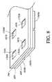
本明細書に開示する実施形態は、複数のサンプルを同時に試験する方法及びデバイスに関する。ある一定の実施形態は、リアルタイム核酸増幅及び検出を実施するための装置を考えている。装置は、複数の光検出器及び光源対を含む検出器ヘッドを含むことができる。検出器ヘッドは、レール上に装着することができ、検出器及び光源対は、第1の横列及び第2の横列に整列される。装置は、第1の横列と第2の横列とに隣接する縦列に整列された複数の独立反応チャンバを有するマイクロ流体カートリッジのためのレセプタクルを含むことができる。装置はまた、カートリッジがレセプタクルに存在している時に、マイクロ流体カートリッジの上に位置決めされるように構成された開口プレートを含むことができる。開口プレートは、レセプタクルがマイクロ流体カートリッジを保持している時に、複数の反応チャンバの各々の上に各々位置合せされた複数の開口を含むことができる。検出器ヘッドは、第1の横列の複数の光検出器及び光源対の各々を開口プレートの第1の横列において各開口の上に位置付けることができ、かつ第2の横列の複数の光検出器及び光源対の各々を開口プレートの第2の横列において各開口の上に位置付けることができるように、開口プレートの上に位置付けられたことができ、かつレールに沿って移動可能にすることができる。 Embodiments disclosed herein relate to methods and devices for simultaneously testing multiple samples. Certain embodiments contemplate an apparatus for performing real-time nucleic acid amplification and detection. The apparatus can include a detector head that includes a plurality of photodetectors and light source pairs. The detector head can be mounted on a rail, and the detector and light source pairs are aligned in a first row and a second row. The apparatus can include a receptacle for a microfluidic cartridge having a plurality of independent reaction chambers aligned in columns adjacent to the first row and the second row. The apparatus can also include an aperture plate configured to be positioned over the microfluidic cartridge when the cartridge is in the receptacle. The aperture plate can include a plurality of apertures each aligned over each of the plurality of reaction chambers when the receptacle holds the microfluidic cartridge. The detector head can position each of the first row of photodetectors and light source pairs over each aperture in the first row of aperture plates, and the second row of photodetectors. And each of the light source pairs can be positioned on the aperture plate and can be movable along the rail so that each of the light source pairs can be positioned on each aperture in the second row of the aperture plate. .
一部の実施形態において、装置はまた、第1の横列及び第2の横列に整列された複数の光検出器及び光源対を有する第2の検出器ヘッドを含む。第2の検出器ヘッドは、レール上に装着することができる。装置はまた、第1の横列と第2の横列とに隣接する縦列に整列された複数の独立反応チャンバを含むマイクロ流体カートリッジのための第2のレセプタクルを含むことができる。装置はまた、第2のカートリッジが第2のレセプタクルに存在している時に、第2のマイクロ流体カートリッジの上に位置決めされるように構成された第2の開口プレートを含むことができ、開口プレートは、第2のレセプタクルが第2のマイクロ流体カートリッジを保持している時に、第2のマイクロ流体カートリッジ内の複数の反応チャンバの各々の上に各々位置合せされた複数の開口を含むことができる。第2の検出器ヘッドは、第2の検出器ヘッドの第1の横列の複数の光検出器及び光源対の各々を第2の開口プレートの第1の横列において各開口の上に位置付けることができ、かつ第2の検出器ヘッドの第2の横列の複数の光検出器及び光源対の各々を第2の開口プレートの第2の横列において各開口の上に位置付けることができるように、開口プレートの上に位置付けられたことができ、かつレールに沿って移動可能にすることができる。 In some embodiments, the apparatus also includes a second detector head having a plurality of photodetectors and light source pairs aligned in the first row and the second row. The second detector head can be mounted on the rail. The apparatus can also include a second receptacle for a microfluidic cartridge that includes a plurality of independent reaction chambers aligned in columns adjacent to the first row and the second row. The apparatus can also include a second aperture plate configured to be positioned over the second microfluidic cartridge when the second cartridge is in the second receptacle. Can include a plurality of apertures each aligned over each of the plurality of reaction chambers in the second microfluidic cartridge when the second receptacle holds the second microfluidic cartridge. . The second detector head positions each of the plurality of photodetectors and light source pairs in the first row of the second detector head over each aperture in the first row of the second aperture plate. Apertures such that each of the plurality of photodetectors and light source pairs in the second row of the second detector head can be positioned over each aperture in the second row of the second aperture plate. It can be positioned on the plate and can be movable along the rail.
一部の実施形態において、光検出器及び光源対は、6つの異なる波長で作動する少なくとも6つの異なる光検出器及び光源対を含むことができる。一部の実施形態において、6つの異なる波長は、緑色光を放出する光源と、黄色光を放出する光源と、オレンジ色光を放出する光源と、赤色光を放出する光源と、深紅色光を放出する光源とを含む。一部の実施形態において、検出器ヘッドは、光検出器及び光源対の少なくともN横列を含み、検出器は、開口のM横列を含む開口プレートの上で少なくともM+N−1位置まで移動するように構成される。 In some embodiments, the photodetector and light source pair can include at least six different photodetector and light source pairs operating at six different wavelengths. In some embodiments, six different wavelengths emit a light source that emits green light, a light source that emits yellow light, a light source that emits orange light, a light source that emits red light, and a light source that emits crimson light. Including a light source. In some embodiments, the detector head includes at least N rows of photodetectors and light source pairs, such that the detector moves to at least an M + N-1 position over an aperture plate that includes M rows of apertures. Composed.
一部の実施形態において、開口プレートは、鋼、アルミニウム、ニッケル、又はこれらの組合せを含む。一部の実施形態において、開口プレートは、約.25インチの厚みを有することができる。一部の実施形態において、開口プレートの少なくとも一部は、開口プレートが電気化学的に酸化されない時よりも黒ずむように電気化学的に酸化される。一部の実施形態において、開口プレートは、カートリッジがレセプタクルに存在している時に、マイクロ流体カートリッジの区域にわたって実質的に均一な圧力を与える。一部の実施形態において、開口プレートは、アルミニウム、亜鉛、又はニッケルのうちの少なくとも1つを含み、開口プレートは、着色剤を更に含む。 In some embodiments, the aperture plate comprises steel, aluminum, nickel, or a combination thereof. In some embodiments, the aperture plate is about. It can have a thickness of 25 inches. In some embodiments, at least a portion of the aperture plate is electrochemically oxidized so that it is darker than when the aperture plate is not electrochemically oxidized. In some embodiments, the aperture plate provides a substantially uniform pressure across the area of the microfluidic cartridge when the cartridge is present in the receptacle. In some embodiments, the aperture plate includes at least one of aluminum, zinc, or nickel, and the aperture plate further includes a colorant.
一部の実施形態において、装置は、加熱器プレートを更に含み、加熱器プレートは、カートリッジがレセプタクルに存在している時にマイクロ流体カートリッジの下に位置決めされる。一部の実施形態において、加熱器プレートは、ガラス又は石英のうちの少なくとも一方を含む。一部の実施形態において、開口プレートは、カートリッジがレセプタクルに存在している時に、マイクロ流体カートリッジの区域にわたって実質的に均一な圧力を与える。実質的に均一な圧力は、マイクロ流体反応チャンバと加熱器プレートの間の実質的に均一な熱的接触を容易にすることができる。従って、一部の実施形態において、開口プレートは、マイクロ流体カートリッジ内の複数の反応チャンバ又はリアクタの各々が、加熱器プレート内に位置付けられたそれぞれの複数の加熱要素と均一な熱的接触又は連通状態にあることを確実することができる均一な圧力を与える。 In some embodiments, the apparatus further includes a heater plate, which is positioned below the microfluidic cartridge when the cartridge is in the receptacle. In some embodiments, the heater plate comprises at least one of glass or quartz. In some embodiments, the aperture plate provides a substantially uniform pressure across the area of the microfluidic cartridge when the cartridge is present in the receptacle. The substantially uniform pressure can facilitate a substantially uniform thermal contact between the microfluidic reaction chamber and the heater plate. Accordingly, in some embodiments, the aperture plate is configured so that each of the plurality of reaction chambers or reactors in the microfluidic cartridge is in uniform thermal contact or communication with each of the plurality of heating elements positioned within the heater plate. Provide a uniform pressure that can be ensured to be in a state.
一部の実施形態において、装置は、開口プレートの上に位置付けられた光検出器を更に含み、マイクロ流体チャンバは、光検出器に対して光源から視射角で光を受け入れるように構成される。一部の実施形態において、加熱器プレートは、複数の加熱要素を含み、複数の加熱要素の各々は、マイクロ流体カートリッジがレセプタクルに存在している時に複数の加熱要素がそれぞれ複数の反応チャンバの各々と熱的接続状態にあるように位置決めされる。 In some embodiments, the apparatus further includes a photodetector positioned over the aperture plate, and the microfluidic chamber is configured to receive light from a light source at a viewing angle relative to the photodetector. . In some embodiments, the heater plate includes a plurality of heating elements, each of the plurality of heating elements having a plurality of heating elements each in the plurality of reaction chambers when the microfluidic cartridge is present in the receptacle. And positioned so as to be in thermal connection.
ある一定の実施形態は、複数の熱サイクル反応を同時に実施するために、ポリメラーゼ連鎖反応(PCR)プロトコルなどのようなプロトコルを最適化するための1つ又はそれよりも多くのコンピュータプロセッサ上に実施される方法を考えている。各熱サイクル反応は、1つ又はそれよりも多くの検出段階を含み、熱サイクル反応は、複数のリアクタにおいて実施される。本方法は、複数のリアクタの各々に対して検出サイクル時間を決定する又は与える又はそれにアクセスする段階と、ステップ持続時間に関連付けられて検出のための時間を含むプロトコルステップを受け入れる又はアクセスする段階と、ステップ持続時間が検出サイクル時間の倍数であるようにステップに対する第1の調節を決定する段階とを含むことができる。 Certain embodiments are performed on one or more computer processors to optimize protocols such as the polymerase chain reaction (PCR) protocol to perform multiple thermal cycling reactions simultaneously. I am thinking how to be. Each thermal cycling reaction includes one or more detection stages, and the thermal cycling reaction is performed in multiple reactors. The method includes determining or providing or accessing a detection cycle time for each of the plurality of reactors, and accepting or accessing a protocol step that includes a time for detection associated with the step duration. Determining a first adjustment to the step such that the step duration is a multiple of the detection cycle time.
一部の実施形態において、本方法は、ステップに対する第2の調節を決定する段階を更に含み、検出のための時間は、ステップが第1の調節により及び第2の調節により調節される時に検出サイクル時間の倍数である。一部の実施形態において、本方法は、プロトコルに関連付けられた反応チャンバの位置に基づいて開始オフセット調節を決定する段階を更に含む。一部の実施形態において、検出サイクル時間は、検出器ヘッドがリアクタに対して所定の複数の検出を実施するのに必要な時間の量を含む。一部の実施形態において、検出サイクル時間は、複数のリアクタの各々への検出器ヘッドの移動及び開始位置への検出器ヘッドの移動に必要な時間を含む。一部の実施形態において、本方法は、プロトコルを開始する段階を更に含む。 In some embodiments, the method further comprises determining a second adjustment for the step, and the time for detection is detected when the step is adjusted by the first adjustment and by the second adjustment. It is a multiple of the cycle time. In some embodiments, the method further includes determining a starting offset adjustment based on the position of the reaction chamber associated with the protocol. In some embodiments, the detection cycle time includes the amount of time required for the detector head to perform a predetermined plurality of detections on the reactor. In some embodiments, the detection cycle time includes the time required for movement of the detector head to each of the plurality of reactors and movement of the detector head to the starting position. In some embodiments, the method further includes initiating a protocol.
ある一定の実施形態は、命令を含む持続性コンピュータ可読媒体を考えており、命令は、1つ又はそれよりも多くのプロセッサをして、検出サイクル時間を決定する又は与える又はそれにアクセスする段階と、ステップ持続時間に関連付けられて検出のための時間を含むプロトコルステップを受け入れる又はアクセスする段階と、ステップ持続時間が検出サイクル時間の倍数であるようにステップに対する第1の調節を決定する段階とを実施させるように構成される。 Certain embodiments contemplate a persistent computer readable medium that includes instructions that determine or provide or access a detection cycle time with one or more processors. Accepting or accessing a protocol step that includes a time for detection associated with the step duration, and determining a first adjustment to the step such that the step duration is a multiple of the detection cycle time. It is configured to be implemented.
一部の実施形態において、プロトコルステップは、複数のプロトコルからのプロトコルに関連付けられる。複数のプロトコルの各々は、ポリメラーゼ連鎖反応(PCR)プロトコルのような複数の熱サイクル反応のうちの少なくとも1つに関連付けることができ、各熱サイクル反応は、1つ又はそれよりも多くの検出段階を含み、第1の調節の決定は、複数のプロトコルのうちの2つ又はそれよりも多くを同時に実行する時に複数のプロトコルのうちの少なくとも2つ又はそれよりも多くの熱サイクル反応に関連付けられた1つ又はそれよりも多くの検出段階のタイミングに少なくとも一部基づいている。一部の実施形態において、本方法はまた、ステップに対する第2の調節を決定する段階を含み、検出のための時間は、ステップが第1の調節により及び第2の調節により調節される時に検出サイクル時間の倍数である。一部の実施形態において、本方法はまた、プロトコルに関連付けられた反応チャンバの位置に基づいて開始オフセット調節を決定する段階を含む。一部の実施形態において、検出サイクル時間は、検出器ヘッドが反応チャンバに対して所定の複数の検出を実施するのに必要な時間の量を含む。一部の実施形態において、検出サイクル時間はまた、複数の反応チャンバ検出位置の各々への検出器ヘッドの移動及び開始位置への検出器ヘッドの移動に必要な時間を含む。一部の実施形態において、本方法は、プロトコルを開始する段階を更に含む。 In some embodiments, protocol steps are associated with protocols from multiple protocols. Each of the plurality of protocols can be associated with at least one of a plurality of thermal cycling reactions, such as a polymerase chain reaction (PCR) protocol, each thermal cycling reaction having one or more detection steps. The determination of the first adjustment is associated with at least two or more thermal cycling reactions of the plurality of protocols when simultaneously executing two or more of the plurality of protocols. Based at least in part on the timing of one or more detection stages. In some embodiments, the method also includes determining a second adjustment for the step, and the time for detection is detected when the step is adjusted by the first adjustment and by the second adjustment. It is a multiple of the cycle time. In some embodiments, the method also includes determining a starting offset adjustment based on the position of the reaction chamber associated with the protocol. In some embodiments, the detection cycle time includes the amount of time required for the detector head to perform a predetermined plurality of detections on the reaction chamber. In some embodiments, the detection cycle time also includes the time required to move the detector head to each of the plurality of reaction chamber detection positions and to move the detector head to the starting position. In some embodiments, the method further includes initiating a protocol.
ある一定の実施形態は、複数の反応チャンバに対してプロトコルを最適化するためのシステムを考えている。システムは、検出サイクル時間を決定する又は与える又はそれにアクセスする段階と、ステップ持続時間に関連付けることができ、かつ検出のための時間を含むプロトコルステップを受け入れる又はアクセスする段階と、ステップ持続時間が検出サイクル時間の倍数であるようにステップに対する第1の調節を決定する段階とを実施するように構成されたプロセッサを含むことができる。 Certain embodiments contemplate a system for optimizing protocols for multiple reaction chambers. The system determines or provides or accesses a detection cycle time, accepts or accesses a protocol step that can be associated with a step duration and includes a time for detection, and a step duration detection And determining a first adjustment to the step to be a multiple of the cycle time.
一部の実施形態において、プロトコルステップは、複数のプロトコルからのプロトコルに関連付けられる。複数のプロトコルの各々は、ポリメラーゼ連鎖反応(PCR)プロトコルのような複数の熱サイクル反応のうちの少なくとも1つに関連付けることができ、各熱サイクル反応は、1つ又はそれよりも多くの検出段階を含み、第1の調節の決定は、複数のプロトコルのうちの2つ又はそれよりも多くが同時に実行される時に複数のプロトコルのうちの少なくとも2つ又はそれよりも多くの熱サイクル反応に関連付けられた1つ又はそれよりも多くの検出段階のタイミングに少なくとも一部基づいている。一部の実施形態において、プロセッサはまた、ステップに対する第2の調節を決定するように構成され、検出のための時間は、ステップが第1の調節により及び第2の調節により調節される時に検出サイクル時間の倍数である。一部の実施形態において、プロセッサはまた、プロトコルに関連付けられた反応チャンバの位置に基づいて開始オフセット調節を決定するように構成される。一部の実施形態において、検出サイクル時間は、検出器ヘッドが反応チャンバに対して所定の複数の検出を実施するのに必要な時間の量を含む。一部の実施形態において、検出サイクル時間はまた、複数の反応チャンバ検出位置の各々への検出器ヘッドの移動及び開始位置への検出器ヘッドの移動に必要な時間を含む。一部の実施形態において、プロセッサは、プロトコルを開始するように更に構成される。 In some embodiments, protocol steps are associated with protocols from multiple protocols. Each of the plurality of protocols can be associated with at least one of a plurality of thermal cycling reactions, such as a polymerase chain reaction (PCR) protocol, each thermal cycling reaction having one or more detection steps. And determining the first adjustment is associated with at least two or more thermal cycling reactions of the plurality of protocols when two or more of the plurality of protocols are performed simultaneously. Based at least in part on the timing of the one or more detection stages provided. In some embodiments, the processor is also configured to determine a second adjustment for the step, and the time for detection is detected when the step is adjusted by the first adjustment and by the second adjustment. It is a multiple of the cycle time. In some embodiments, the processor is also configured to determine a starting offset adjustment based on the position of the reaction chamber associated with the protocol. In some embodiments, the detection cycle time includes the amount of time required for the detector head to perform a predetermined plurality of detections on the reaction chamber. In some embodiments, the detection cycle time also includes the time required to move the detector head to each of the plurality of reaction chamber detection positions and to move the detector head to the starting position. In some embodiments, the processor is further configured to initiate the protocol.
ある一定の実施形態は、(a)検出器アセンブリが、少なくとも1つの検出可能信号に対して複数のPCR反応チャンバの各々を走査し、かつ走査を繰り返す待機状態になることができる走査サイクルを実施するのに十分な走査時間を与える段階と、(b)各サイクルが、少なくとも1つの加熱段階と、少なくとも1つの冷却段階と、検出器アセンブリが少なくとも1つの検出可能信号に対して反応チャンバを走査することになる読取サイクル期間を含む少なくとも1つの温度プラトーとを含むサイクル時間を含む複数のサイクルを含むPCR反応チャンバの各々に対する反応プロトコルを与える段階と、(c)プロセッサを使用して、その反応チャンバに対するサイクル時間が走査時間と同じか又はその整数倍数であるか否かを決定し、かつそうでない場合に、サイクル時間が走査時間と同じか又はその整数倍数であるように走査時間又はサイクル時間を調節する段階と、(d)各反応プロトコルに対するサイクル時間が走査時間と同じか又はその整数倍数であるように、複数のPCR反応チャンバの各々に対する反応プロトコルに対して少なくとも段階(b)及び(c)を実施する段階と、(e)プロセッサの指示の下で、各PCR反応チャンバがその反応チャンバに対する各読取サイクル期間中に検出器アセンブリによって走査される検出器アセンブリによって複数の走査サイクルを実施する段階を含む反応チャンバの各々に対する反応プロトコルを使用して反応チャンバの各々に対してリアルタイムPCRを実施する段階とを含む複数のPCR反応チャンバにおいてリアルタイムPCRを同時に実施する方法を考えている。 Certain embodiments implement a scan cycle in which (a) the detector assembly can scan each of the plurality of PCR reaction chambers for at least one detectable signal and be ready to repeat the scan. Providing a scan time sufficient to: (b) each cycle comprising at least one heating stage, at least one cooling stage, and a detector assembly scanning the reaction chamber for at least one detectable signal; Providing a reaction protocol for each of the PCR reaction chambers including a plurality of cycles including a cycle time including at least one temperature plateau including a read cycle period to be performed, and (c) using the processor to Determine whether the cycle time for the chamber is the same as or an integral multiple of the scan time; Otherwise, adjusting the scan time or cycle time such that the cycle time is the same as or an integer multiple of the scan time; and (d) the cycle time for each reaction protocol is the same as or an integer of the scan time. Performing at least steps (b) and (c) for the reaction protocol for each of the plurality of PCR reaction chambers to be a multiple, and (e) under the direction of the processor, each PCR reaction chamber has its Real-time PCR for each of the reaction chambers using a reaction protocol for each of the reaction chambers that includes performing a plurality of scan cycles with the detector assembly that is scanned by the detector assembly during each read cycle for the reaction chamber. Performing in a plurality of PCR reaction chambers including We are considering how to implement Im PCR simultaneously.
一部の実施形態において、本方法は、反応チャンバのうちの少なくとも1つに対して反応プロトコルのサイクル時間を調節する段を更に含む。一部の実施形態において、少なくとも1つのこの反応プロトコルは、別のこの反応プロトコルとは異なる。一部の実施形態において、1つの反応プロトコルにおける少なくとも1つのサイクル時間は、別の反応プロトコルにおけるサイクル時間とは異なる。 In some embodiments, the method further includes adjusting a cycle time of the reaction protocol for at least one of the reaction chambers. In some embodiments, at least one of the reaction protocols is different from another of the reaction protocols. In some embodiments, at least one cycle time in one reaction protocol is different from the cycle time in another reaction protocol.
本発明の実施形態のある一定のものは、マイクロ流体チャンバを一貫して加熱及び分析することができる本明細書に熱サイクラーと呼ぶ装置を考えている。リアルタイムPCRなどによるポリヌクレオチド増幅は、マイクロ流体チャンバ内で実施することができる。一部の実施形態において、熱サイクラーは、マイクロ流体カートリッジ内の複数のマイクロ流体反応チャンバにおいて個々の熱サイクリング及び検出プロトコルを実施するように構成することができる。熱サイクリングを使用して、核酸、例えば、DNA又はRNAなどを例えばマイクロ流体反応チャンバ内で本明細書に説明するリアルタイムPCR又は他の核酸増幅プロトコルによって増幅することができる。熱サイクラーは、複数の検出器対、例えば、6つ又はそれよりも多くの検出器ヘッド対を含む検出器ヘッドを含むことができ、各検出器対は、光源、例えば、LEDなど、及び同属の光ダイオードを含む。一部の実施形態において、各個々の検出器対は、蛍光部分、例えば、蛍光プローブから放出された光を発生及び検出してターゲットポリヌクレオチドの存在を示すように構成される。 Certain of the embodiments of the present invention contemplate an apparatus referred to herein as a thermal cycler that can consistently heat and analyze a microfluidic chamber. Polynucleotide amplification such as by real-time PCR can be performed in a microfluidic chamber. In some embodiments, the thermal cycler can be configured to perform individual thermal cycling and detection protocols in multiple microfluidic reaction chambers within the microfluidic cartridge. Thermal cycling can be used to amplify nucleic acids, such as DNA or RNA, for example, in a microfluidic reaction chamber by real-time PCR or other nucleic acid amplification protocols described herein. The thermal cycler can include a plurality of detector pairs, eg, detector heads including six or more detector head pairs, each detector pair comprising a light source, eg, an LED, and the like. Including photodiodes. In some embodiments, each individual detector pair is configured to generate and detect light emitted from a fluorescent moiety, eg, a fluorescent probe, to indicate the presence of the target polynucleotide.
本明細書に使用される場合に、用語「マイクロ流体」は、1ml未満、好ましくは、0.9ml未満、例えば、0.8ml、0.7ml、0.6ml、0.5ml、0.4ml、0.3ml、0.2ml、0.1ml、90μl、80μl、70μl、60μl、50μl、40μl、30μl、20μl、10μl、5μl、4μl、3μl、2μl、1μl、又はそれ未満の容積、又はその中間のあらゆる量を意味する。具体的にその反対が明らかにされない限り、本明細書で用語PCRを使用する場合、以下に限定されるものではないが、リアルタイム及び定量的PCR、並びにポリヌクレオチド増幅のあらゆる他の形態を含むPCRのあらゆる変形を包含することを意図していることは理解されるものとする。 As used herein, the term “microfluidic” means less than 1 ml, preferably less than 0.9 ml, such as 0.8 ml, 0.7 ml, 0.6 ml, 0.5 ml, 0.4 ml, 0.3 ml, 0.2 ml, 0.1 ml, 90 μl, 80 μl, 70 μl, 60 μl, 50 μl, 40 μl, 30 μl, 20 μl, 10 μl, 5 μl, 4 μl, 3 μl, 2 μl, 1 μl, or less, or intermediate Means any amount. Unless specifically stated to the contrary, the term PCR as used herein includes, but is not limited to, real-time and quantitative PCR, and PCR, including all other forms of polynucleotide amplification It should be understood that it is intended to encompass any variation of
分析において使用する検出処理は、多重化されて同時に複数の反応に対して複数の同時測定を可能にすることもできる。一部の実施形態において、これらの測定は、個別の反応チャンバから取ることができる。これらの実施形態のある一定のものは、単一PCR反応チャンバにおいて複数のPCR反応、例えば、多重PCRを同時に実施する。PCRプロトコルは、検出前に反応チャンバにおいてポリヌクレオチドの連続焼きなまし及び変性を実施するための指針を含むことができる。チャンバを加熱するための時間プロフィールを含むかかる指針は、「プロトコル」と呼ぶことができる。開示する実施形態のある一定のものは、センサアレイを使用して検出を可能にしながら、PCRを実施する複数の反応チャンバにわたって一貫した加熱及び/又は冷却を可能にする。ある一定の実施形態において、装置は、複数のPCR反応チャンバを収容するカートリッジに圧力を印加することによって反応チャンバの一貫した加熱及び冷却を可能にする開口プレートを含むことができる。ポリヌクレオチドを処理するためのある一定の詳細及び方法は、本明細書に引用により組み込まれている例えば米国特許出願公開第2009−0131650号明細書及び米国特許出願公開第2010−0009351号明細書に見出すことができる。 The detection process used in the analysis can be multiplexed to allow multiple simultaneous measurements for multiple reactions at the same time. In some embodiments, these measurements can be taken from separate reaction chambers. Certain of these embodiments perform multiple PCR reactions simultaneously, eg, multiplex PCR, in a single PCR reaction chamber. The PCR protocol can include guidelines for performing continuous annealing and denaturation of the polynucleotide in the reaction chamber prior to detection. Such guidelines including a time profile for heating the chamber can be referred to as a “protocol”. Certain of the disclosed embodiments allow for consistent heating and / or cooling across multiple reaction chambers performing PCR while allowing detection using a sensor array. In certain embodiments, the apparatus can include an aperture plate that allows for consistent heating and cooling of the reaction chamber by applying pressure to a cartridge containing a plurality of PCR reaction chambers. Certain details and methods for processing polynucleotides are described in, for example, US Patent Application Publication No. 2009-0131650 and US Patent Application Publication No. 2010-0009351, which are incorporated herein by reference. Can be found.
本明細書に開示する実施形態が様々なタイプの核酸増幅反応に有用であることを当業者は認めるであろう。例えば、本明細書に開示する実施形態に関連する核酸増幅の方法は、以下に限定されるものではないが、ポリメラーゼ連鎖反応(PCR)、鎖置換増幅(SDA)、例えば、多置換増幅(MDA)、ループ媒介性等温増幅(LAMP)、リガーゼ連鎖反応(LCR)、免疫増幅、及び転写媒介性増幅(TMA)、核酸配置ベース増幅(NASBA)、自家持続配置複製法(3SR)、及びローリングサークル増幅を含む様々な転写ベース増幅手順を含むことができる。例えば、Mullis著「核酸配置を増幅、検出、及び/又はクローニングするための処理」、米国特許第4,683,195号明細書、Walker著「鎖置換増幅」、米国特許第5,455,166号明細書、Dean他著「多置換増幅」、米国特許第6,977,148号明細書、Notomi他著「核酸を合成するための処理」、米国特許第6,410,278号明細書、Landegren他著「核酸におけるヌクレオチド変化を検出する方法」、米国特許第4,988,617号明細書、Birkenmeyer著「間隙充填リガーゼ連鎖反応を使用するターゲット核酸の増幅」、米国特許第5,427,930号明細書、Cashman著「ブロックポリメラーゼポリヌクレオチド免疫測定法及びキット」、米国特許第5,849,478号明細書、Kacian他著「核酸配置増幅法」、米国特許第5,399,491号明細書、Malek他著「強化核酸増幅処理」、米国特許第5,130,238号明細書、Lizardi他著「BioTechnology」、6:1197(1988)、Lizardi他著「ローリングサークル複製リポータシステム」、米国特許第5,854,033号明細書を参照されたい。 One skilled in the art will appreciate that the embodiments disclosed herein are useful for various types of nucleic acid amplification reactions. For example, methods of nucleic acid amplification related to the embodiments disclosed herein are not limited to the following: polymerase chain reaction (PCR), strand displacement amplification (SDA), eg, multiple displacement amplification (MDA) ), Loop-mediated isothermal amplification (LAMP), ligase chain reaction (LCR), immune amplification, and transcription-mediated amplification (TMA), nucleic acid configuration-based amplification (NASBA), self-sustained configuration replication (3SR), and rolling circle Various transcription-based amplification procedures, including amplification, can be included. For example, Mullis, “Process for Amplifying, Detecting, and / or Cloning Nucleic Acid Configurations”, US Pat. No. 4,683,195, Walker, “Strand Displacement Amplification”, US Pat. No. 5,455,166. Dean et al., “Multiple Displacement Amplification”, US Pat. No. 6,977,148, Notomi et al., “Process for Synthesizing Nucleic Acids”, US Pat. No. 6,410,278, Landegren et al., “Methods for Detecting Nucleotide Changes in Nucleic Acids”, US Pat. No. 4,988,617, Birkenmeyer, “Amplification of Target Nucleic Acids Using Gap Filled Ligase Chain Reaction”, US Pat. No. 5,427, 930, Cashman, “Block polymerase polynucleotide immunoassay and kit”, US Pat. No. 5,8. No. 9,478, Kacian et al., “Nucleic acid configuration amplification method”, US Pat. No. 5,399,491, Malek et al., “Enhanced nucleic acid amplification treatment”, US Pat. No. 5,130,238. Lizardi et al., “BioTechnology”, 6: 1197 (1988), Lizardi et al., “Rolling Circle Replication Reporter System”, US Pat. No. 5,854,033.
本明細書に開示する一部の実施形態において、ターゲット核酸、例えば、ターゲットアンプリコンは、オリゴヌクレオチドプローブを使用して検出することができる。好ましくは、プローブは、本明細書に開示するシステムによって検出することができる1つ又はそれよりも多くの検出可能部分を含む。いくつかのプローブ技術が本明細書に開示する実施形態において有用であるということを当業者は認めるであろう。一例として、本明細書に開示する実施形態は、TAQMAN(登録商標)プローブ、分子ビーコンプローブ、SCORPION(登録商標)プローブなどと共に使用することができる。 In some embodiments disclosed herein, a target nucleic acid, eg, a target amplicon, can be detected using an oligonucleotide probe. Preferably, the probe includes one or more detectable moieties that can be detected by the systems disclosed herein. Those skilled in the art will appreciate that a number of probe techniques are useful in the embodiments disclosed herein. As an example, the embodiments disclosed herein can be used with TAQMAN® probes, molecular beacon probes, SCORPION® probes, and the like.
TaqMan(登録商標)分析は、ポリヌクレオチドを検出するための均質分析である(米国特許第5,723,591号明細書を参照)。TAQMAN(登録商標)分析において、2つのPCRプライマは、中心TAQMAN(登録商標)プローブオリゴヌクレオチドの側部に位置決めされる。プローブオリゴヌクレオチドは、燐光体及び消光剤を含有する。PCR処理の重合段階中に、ポリメラーゼの5’ヌクレアーゼ活性は、プローブオリゴヌクレオチドを劈開し、消光剤から燐光体部分を物理的に分離させ、これは、蛍光放出を増加させる。より多くのPCR生成物が作り出される時に、新しい波長における放出強度は増大する。 TaqMan® analysis is a homogeneous analysis for detecting polynucleotides (see US Pat. No. 5,723,591). In the TAQMAN® analysis, the two PCR primers are positioned on the side of the central TAQMAN® probe oligonucleotide. The probe oligonucleotide contains a phosphor and a quencher. During the polymerization phase of the PCR process, the 5 'nuclease activity of the polymerase cleaves the probe oligonucleotide and physically separates the phosphor moiety from the quencher, which increases fluorescence emission. As more PCR product is created, the emission intensity at the new wavelength increases.
分子ビーコンは、ポリヌクレオチドの検出のためのTAQMAN(登録商標)プローブの代替手段であり、例えば、米国特許第6,277,607号明細書、米国特許第6,150,097号明細書、及び米国特許第6,037,130号明細書に説明されている。分子ビーコンは、完全に適合されたテンプレートに結合する時に立体構造変化を受けるオリゴヌクレオチドヘアピンである。オリゴヌクレオチドの立体構造変化は、オリゴヌクレオチド上に存在する燐光体部分と消光剤部分の間の物理的距離を増大させる。物理的距離のこの増大により、消光剤の影響を低下させ、従って、燐光体から生じる信号を増加させる。 Molecular beacons are an alternative to TAQMAN® probes for the detection of polynucleotides, eg, US Pat. No. 6,277,607, US Pat. No. 6,150,097, and This is described in US Pat. No. 6,037,130. Molecular beacons are oligonucleotide hairpins that undergo a conformational change when bound to a fully adapted template. The conformational change of the oligonucleotide increases the physical distance between the phosphor moiety and the quencher moiety present on the oligonucleotide. This increase in physical distance reduces the effect of the quencher and thus increases the signal originating from the phosphor.
隣接プローブ方法は、ターゲット配置の隣接する領域に雑種を形成する2つの核酸プローブの存在下でポリメラーゼ連鎖反応によってターゲット配置を増幅し、プローブの一方は、アクセプター燐光体でラベル付けされ、他方のプローブは、蛍光エネルギ伝達対のドナー燐光体でラベル付けされる。ターゲット配置で2つのプローブを雑種形成すると、ドナー燐光体は、アクセプター燐光体と相互作用して検出可能信号を発生させる。サンプルは、次に、ドナー燐光体によって吸収された波長の光によって励起され、蛍光エネルギ伝達対からの蛍光放出は、そのターゲット量の決定のために検出される。米国特許第6,174,670号明細書は、かかる方法を開示している。 The adjacent probe method amplifies the target configuration by polymerase chain reaction in the presence of two nucleic acid probes that form hybrids in adjacent regions of the target configuration, one of the probes is labeled with an acceptor phosphor and the other probe Are labeled with a donor phosphor of a fluorescent energy transfer pair. When the two probes are hybridized in the target configuration, the donor phosphor interacts with the acceptor phosphor to generate a detectable signal. The sample is then excited by the wavelength of light absorbed by the donor phosphor, and the fluorescence emission from the fluorescence energy transfer pair is detected for determination of its target amount. US Pat. No. 6,174,670 discloses such a method.
サンライズプライマーは、分子ビーコンに類似するが、プライマーとして機能するターゲット結合配置に取りつけられたヘアピン構造を利用する。プライマーの相補的ストランドが合成される時に、ヘアピン構造は破壊され、それによって消光を排除する。これらのプライマーは、増幅生成物を検出し、5’エクソヌクレアーゼ活性を有するポリメラーゼの使用を必要としない。サンライズプライマーは、Nazarenko他、「Nucleic Acids Res.」、25:2516−21(1997)及び米国特許第5,866,336号明細書に説明されている。 Sunrise primers are similar to molecular beacons but utilize a hairpin structure attached to a target binding arrangement that functions as a primer. When the complementary strand of the primer is synthesized, the hairpin structure is destroyed, thereby eliminating quenching. These primers detect the amplification product and do not require the use of a polymerase with 5 'exonuclease activity. Sunrise primers are described in Nazarenko et al., “Nucleic Acids Res.”, 25: 2516-21 (1997) and US Pat. No. 5,866,336.
SCORPION(登録商標)プローブは、サンライズプライマーに類似する付加的なヘアピン構造とプライマーを組み合わせる。しかし、SCORPION(登録商標)プローブのヘアピン構造は、相補的ストランドの合成によるがプライマーに雑種を形成する部分から下流にあるターゲットの一部分とヘアピン構造の一部の雑種形成によって開いていない。 The SCORPION® probe combines a primer with an additional hairpin structure similar to a sunrise primer. However, the hairpin structure of the SCORPION® probe is not opened by hybridization of a part of the target and a part of the hairpin structure downstream from the part that hybridizes to the primer, but by synthesis of complementary strands.
DzyNA−PCRは、DNAzymeのアンチセンス配置を含有するプライマーと、特定のRNAホスホジエステル結合を劈開することができるオリゴヌクレオチドとを伴う。プライマーは、ターゲット配置に結合し、活性DNAzymeを含有するアンプリコンを生成する増幅反応を駆動する。次に、活性なDNAzymeは、反応混合物の一般的なレポーター基質を劈開する。レポーター基質は、燐光体−消光剤対を含有し、基質の劈開により、ターゲット配置の増幅と共に増加する蛍光信号を生成する。DNAzy−PCRは、Todd他、「Clin.Chem.」、46:625−30(2000)及び米国特許第6,140,055号明細書に説明されている。 DzyNA-PCR involves a primer containing the antisense configuration of DNAzyme and an oligonucleotide capable of cleaving specific RNA phosphodiester bonds. The primer binds to the target configuration and drives an amplification reaction that produces an amplicon containing active DNAzyme. The active DNAzym then cleaves the general reporter substrate of the reaction mixture. The reporter substrate contains a phosphor-quencher pair, and cleavage of the substrate produces a fluorescent signal that increases with amplification of the target configuration. DNAzy-PCR is described in Todd et al., “Clin. Chem.”, 46: 625-30 (2000) and US Pat. No. 6,140,055.
Fiandaca他は、消光剤ラベル付けペプチド核酸(Q−PNA)プローブ及び燐光体ラベル付けオリゴヌクレオチドプライマーを利用してPCR分析のための蛍光発生法を説明している。Fiandaca他、「Genome Research.」、11:609−613(2001).Q−PNAは、プライマーの5’末端にあるタグ配置に雑種を形成する。 Fiandaca et al. Describe a fluorescence generation method for PCR analysis utilizing a quencher-labeled peptide nucleic acid (Q-PNA) probe and a phosphor-labeled oligonucleotide primer. Fiandaca et al., “Genome Research.”, 11: 609-613 (2001). Q-PNA forms a hybrid in the tag arrangement at the 5 'end of the primer.
Li他は、反対のオリゴヌクレオチドストランド上に消光剤及び燐光体を有する二重鎖プローブを説明している。Li他、「Nucleic Acids Research.」、30(2):e5,1−9(2002).ターゲットに縛られないと、ストランドは互いに雑種を形成し、プローブは消光される。しかし、ターゲットが存在すると、少なくとも1つのストランドは、蛍光信号を生じるターゲットに雑種を形成する。 Li et al. Describe a duplex probe having a quencher and phosphor on opposite oligonucleotide strands. Li et al., “Nucleic Acids Research.”, 30 (2): e5, 1-9 (2002). When not tied to the target, the strands hybridize with each other and the probe is quenched. However, in the presence of the target, at least one strand forms a hybrid with the target that produces a fluorescent signal.
本明細書に開示する実施形態において有用な燐光体ラベル及び部分は、以下に限定されるものではないが、蛍光色素系、カルボキシローダミン系、シアニン系、及びローダミン系の色素を含む。本発明において使用することができる他の系の色素は、例えば、ポリハロ蛍光色素系色素、ヘキサクロロ蛍光色素系色素、クマリン系色素、オキサジン系色素、チアジン系色素、スクワレン系色素、キレートランタニド系色素、「Molecular Probes」から銘柄「Alexa Fluor J」で入手可能な色素系、及びInvitrogen(米国カリフォルニア州のカールズバッド)から銘柄「Bodispy J」で入手可能な色素系を含む。蛍光色素系の色素は、例えば、6−カルボキシ蛍光色素(FAM)、2’,4’,1,4−テトラクロロ蛍光色素(TET)、2’,4’,5’,7’,1,4−ヘキサクロロ蛍光色素(HEX)、2’,7’−ジメトキシ−4’,5’−ジクロロ−6−カルボキシローダミン(JOE)、2’−クロロ−5’−フルオロ−7’,8’−溶融フェニル−1,4−ジクロロ−6−カルボキシ蛍光色素(NED)、2’−クロロ−7’−フェニル−1,4−ジクロロ−6−カルボキシ蛍光色素(VIC)、6−カルボキシ−X−ローダミン(ROX)、及び2’,4’,5’,7’−テトラクロロ−5−カルボキシ蛍光色素(ZOE)を含む。カルボキシローダミン系の色素は、テトラメチル−6−カルボキシローダミン(TAMRA)、テトラプロパノ−6−カルボキシローダミン(ROX)、テキサスレッド、R110、及びR6Gを含む。シアニン系の色素は、Cy2、Cy3、Cy3.5、Cy5、Cy5.5、及びCy7を含む。燐光体は、例えば、パーキン−エルマー(米国カリフォルニア州フォスターシティ)、モレキュラー・プローブズ・インコーポレーテッド(米国オレゴン州ユージーン)、及びアマシャム・GE・ヘルスケア(米国ニュージャージー州ピスカタウェイ)から市販で容易に利用可能である。 Phosphor labels and moieties useful in the embodiments disclosed herein include, but are not limited to, fluorescent dye-based, carboxyrhodamine-based, cyanine-based, and rhodamine-based dyes. Other dyes that can be used in the present invention include, for example, polyhalo fluorescent dyes, hexachloro fluorescent dyes, coumarin dyes, oxazine dyes, thiazine dyes, squalene dyes, chelate lanthanide dyes, Includes a dye system available under the name “Alexa Fluor J” from “Molecular Probes” and a dye system available under the name “Bodyspy J” from Invitrogen (Carlsbad, Calif.). Examples of fluorescent dyes include 6-carboxy fluorescent dye (FAM), 2 ′, 4 ′, 1,4-tetrachloro fluorescent dye (TET), 2 ′, 4 ′, 5 ′, 7 ′, 1, 4-hexachloro fluorescent dye (HEX), 2 ', 7'-dimethoxy-4', 5'-dichloro-6-carboxyrhodamine (JOE), 2'-chloro-5'-fluoro-7 ', 8'-melt Phenyl-1,4-dichloro-6-carboxy fluorescent dye (NED), 2′-chloro-7′-phenyl-1,4-dichloro-6-carboxy fluorescent dye (VIC), 6-carboxy-X-rhodamine ( ROX), and 2 ', 4', 5 ', 7'-tetrachloro-5-carboxy fluorescent dye (ZOE). Carboxyrhodamine-based dyes include tetramethyl-6-carboxyrhodamine (TAMRA), tetrapropano-6-carboxyrhodamine (ROX), Texas Red, R110, and R6G. The cyanine dyes include Cy2, Cy3, Cy3.5, Cy5, Cy5.5, and Cy7. Phosphors are readily available commercially from, for example, Perkin-Elmer (Foster City, Calif., USA), Molecular Probes, Inc. (Eugene, OR, USA), and Amersham GE Healthcare (Piscataway, NJ, USA) It is.
上述したように、一部の実施形態において、本明細書に開示する実施形態に有用なプローブは、消光剤を含むことができる。消光剤は、蛍光消光剤又は非蛍光消光剤とすることができる。蛍光消光剤は、以下に限定されるものではないが、TAMRA、ROX、DABCYL、DABSYL、ニトロチアゾールブルー(NTB)を含むシアニン色素、アントラキノン、マラカイトグリーン、ニトロチアゾール、及びニトロイミダゾール化合物を含む。燐光体から吸収されたエネルギを消散させる例示的な非蛍光消光剤は、バイオサーチ・テクノロジーズ・インコーポレーテッド(米国カリフォルニア州ナヴァト)から銘柄「Black Hole(登録商標)」で入手可能なもの、エポック・バイオサイエンシーズ(米国ワシントン州ボセル)から銘柄Eclipse(登録商標)で入手可能なもの、アナスペック・インコーポレーテッド(米国カリフォルニア州サンノゼ)から銘柄Qxljで入手可能なもの、及びインテグレート・DNA・テクノロジーズ(米国アイオワオ州コーラルビル)から銘柄「Iowa Black(登録商標)」で入手可能なものを含む。 As noted above, in some embodiments, probes useful in the embodiments disclosed herein can include a quencher. The quencher can be a fluorescence quencher or a non-fluorescence quencher. Fluorescence quenchers include, but are not limited to, cyanine dyes including TAMRA, ROX, DABCYL, DABSYL, nitrothiazole blue (NTB), anthraquinone, malachite green, nitrothiazole, and nitroimidazole compounds. Exemplary non-fluorescent quenchers that dissipate energy absorbed from the phosphor are those available from Biosearch Technologies Inc. (Navart, Calif., USA) under the designation “Black Hole®”, Epoch Available from Biosciences (Bothell, Washington, USA) under the brand Eclipse®, from Anaspec Inc. (San Jose, Calif.) Under the brand Qxlj, and Integrated DNA Technologies (US) Including those available under the name “Iowa Black®” from Coralville, Iowa).
上述の一部の実施形態において、燐光体及び消光剤は、一緒に使用され、かつ同じか又は異なるオリゴヌクレオチド上とすることができる。組み合わせると、燐光体及び蛍光消光剤は、それぞれドナー燐光体及びアクセプター燐光体と呼ぶことができる。いくつかの有利な燐光体/消光剤対は、当業技術で公知であり(例えば、Glazer他著「Current Opinion in Biotechnology」,1997;8:94−102;Tyagi他、1998,Nat.Biotechnol.,16:49−53)、例えば、モレキュラー・プローブズ(米国オレゴン州ジャンクションシティ)及びアプライド・バイオシステムズ(米国カリフォルニア州フォスターシティ)から市販で容易に利用可能である。様々なアクセプター燐光体と共に使用することができるドナー燐光体の例は、以下に限定されるものではないが、蛍光色素、ルシファーイエロー、B−フィコエリトリン、9−アクリジンイソシアネート、ルシファーイエローVS、4−アセトアミド−4’−イソチオ−シアネートスチルベン−2,2’−ジスルホン酸、7−ジエチルアミノ−3−(4’−イソチオシアネートフェニル)−4−メチルクマリン、スクシンイミジル 1−ピレンブチレート、及び4−アセトアミド−4’−イソチオシアネートスチルベン−2−,2’−ジスルホン酸誘導体を含む。アクセプター燐光体は、典型的には、使用するドナー燐光体に依存する。アクセプター燐光体の例は、以下に限定されるものではないが、LC−Red 640、LC−Red 705、Cy5、Cy5.5、リサミンローダミンBスルホニルクロリド、テトラメチルローダミンイソチオシアネート、ローダミンxイソチオシアネート、エリスロシンイソチオシアネート、蛍光色素、ジエチレントリアミンペンタアセテート又はランタニドイオンの他のキレート(例えば、ユーロピウム又はテルビウム)を含む。ドナー及びアクセプター燐光体は、例えば、モレキュラー・プローブズ又はシグマ・ケミカル・コーポレーション(米国ミズーリー州セントルイス)から市販で容易に利用可能である。本明細書に開示する組成物及び方法において有用な燐光体/消光剤対は、当業技術で公知であり、例えば、ワールドワイドウェブサイトmolecular−beacons.org/download/marras,mmb06%28335%293.pdf(2012年4月11日現在)において利用可能なS.Marras著「蛍光核酸雑種形成プローブに対する燐光体及び消光剤対の選択」に説明され、かつ見出すことができる。 In some embodiments described above, the phosphor and the quencher are used together and can be on the same or different oligonucleotides. When combined, the phosphor and the fluorescence quencher can be referred to as a donor phosphor and an acceptor phosphor, respectively. Several advantageous phosphor / quencher pairs are known in the art (see, for example, Glazer et al., "Current Opinion in Biotechnology", 1997; 8: 94-102; Tyagi et al., 1998, Nat. Biotechnol. 16: 49-53), for example, from Molecular Probes (Junction City, Oregon, USA) and Applied Biosystems (Foster City, CA, USA). Examples of donor phosphors that can be used with various acceptor phosphors include, but are not limited to, fluorescent dyes, lucifer yellow, B-phycoerythrin, 9-acridine isocyanate, lucifer yellow VS, 4-acetamide. 4′-isothio-cyanate stilbene-2,2′-disulfonic acid, 7-diethylamino-3- (4′-isothiocyanatophenyl) -4-methylcoumarin, succinimidyl 1-pyrenebutyrate, and 4-acetamide-4 Includes' -isothiocyanate stilbene-2-, 2'-disulfonic acid derivatives. The acceptor phosphor typically depends on the donor phosphor used. Examples of acceptor phosphors include but are not limited to LC-Red 640, LC-Red 705, Cy5, Cy5.5, Lisamin rhodamine B sulfonyl chloride, tetramethylrhodamine isothiocyanate, rhodamine x isothiocyanate. Erythrosine isothiocyanate, fluorescent dyes, diethylenetriaminepentaacetate or other chelates of lanthanide ions such as europium or terbium. Donor and acceptor phosphors are readily available commercially, for example, from Molecular Probes or Sigma Chemical Corporation (St. Louis, MO, USA). Phosphor / quencher pairs useful in the compositions and methods disclosed herein are known in the art and are described, for example, on the worldwide website beacon. org / download / marras, mmb06% 28335% 293. S. pdf available in pdf (as of April 11, 2012). Marras "Selection of phosphor and quencher pairs for fluorescent nucleic acid hybridization probes" can be found and found.
本明細書に開示する分析において使用する検出処理は、複数の検出可能部分、例えば、異なる検出可能部分を含有する複数のプローブのような複数の同時測定を有利に可能にする。一部の実施形態において、これらの測定値は、マイクロ流体カートリッジ内の例えばチャンバ層(本明細書で反応チャンバを収容するマイクロ流体カートリッジのその部分を参照するチャンバ層)を含む個別の反応チャンバから取ることができる。これらの実施形態のある一定のものは、単一反応チャンバにおいて複数の増幅反応、例えば、多重PCRを同時に実施する。PCRプロトコルは、検出前に反応チャンバにおいてポリヌクレオチドの連続焼きなまし及び変性を実施するための指針を含むことができる。一部の実施形態において、装置は、複数の反応チャンバにわたって一貫した加熱及び/又は冷却を可能にし、核酸増幅を実施し、センサアレイを使用して、例えば、蛍光放出を検出することによって個々の反応チャンバにおいてターゲットアンプリコンの検出を可能にするように構成される。 The detection process used in the analysis disclosed herein advantageously allows multiple simultaneous measurements, such as multiple probes that contain multiple detectable moieties, eg, different detectable moieties. In some embodiments, these measurements are taken from individual reaction chambers including, for example, a chamber layer (a chamber layer that refers to that portion of the microfluidic cartridge that houses the reaction chamber herein) within the microfluidic cartridge. Can be taken. Certain of these embodiments perform multiple amplification reactions, eg, multiplex PCR, simultaneously in a single reaction chamber. The PCR protocol can include guidelines for performing continuous annealing and denaturation of the polynucleotide in the reaction chamber prior to detection. In some embodiments, the device allows for consistent heating and / or cooling across multiple reaction chambers, performs nucleic acid amplification, and uses a sensor array to detect individual, for example, by detecting fluorescence emission. It is configured to allow detection of the target amplicon in the reaction chamber.
一部の実施形態において、装置は、複数の独立の光学対を通じて複数の反応チャンバを収容するカートリッジに圧力を印加することによって反応チャンバの一貫した加熱及び冷却を可能にする開口プレートを含むことができる。開口プレートは、好ましくは、複数の独立反応チャンバ内のプローブからの蛍光信号の発生及び検出を可能かつ容易にするように構成される。一部の実施形態において、開口プレートは、マイクロ流体カートリッジにおいて個々の反応チャンバの各々の上に位置決めされた個々の開口(又は窓)があるように構成される。 In some embodiments, the apparatus can include an aperture plate that allows for consistent heating and cooling of the reaction chamber by applying pressure to a cartridge containing multiple reaction chambers through multiple independent optical pairs. it can. The aperture plate is preferably configured to allow and facilitate the generation and detection of fluorescent signals from probes in multiple independent reaction chambers. In some embodiments, the aperture plate is configured such that there are individual apertures (or windows) positioned on each of the individual reaction chambers in the microfluidic cartridge.
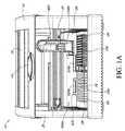
診断装置
図1A及び図1Bは、この一部の実施形態の診断装置10を示している。図1Aに示す実施形態において、診断装置は、装置ハウジング30を含む。ハウジング30は、マイクロ流体サンプルを処理し、かつ望ましくない光が検出空間に入るのを阻止するように制御された環境を確実することができる。ハウジング30は、ハンドル14及び半透明窓12を含むカバー16を含むことができる。カバー16を下ろして、診断装置10が作動状態にある時に診断装置10の前の開口部を閉じることができる。Diagnostic Device FIGS. 1A and 1B show a
図1A及び図1Bの実施形態で見られるように、診断装置10は、診断装置10の前側部分に2つの試料ラック24a、24bを収容することができる。しかし、図1A及び図1Bの診断装置の描写が例示に過ぎず、一部の実施形態において、装置は、2つよりも多くの試料ラック、例えば、3つ、4つ、5つ、6つ、7つ、8つ、9つ、10、又はそれよりも多くの試料ラックを収容するように構成することができることを当業者は認めるであろう。好ましくは、装置は、同数の試料ラック、例えば、マイクロ流体カートリッジとして2つを収容するように構成される。 As seen in the embodiment of FIGS. 1A and 1B, the
一部の実施形態において、各試料ラック24a、24bは、複数のホルダ26を含むことができる。ホルダ26は、核酸増幅のための試薬、例えば、PCR試薬などのような診断試薬を保持するためのレセプタクルを含むことができる。ラック24はまた、試料チューブ(図示せず)及び増幅待機サンプルのような診断待機サンプルを調製するための混合チューブ(図示せず)を含むことができる。装置は、ディスペンサ400を使用してラック24a、24bに望ましい試薬を調製することができる。様々な流体ディスペンサの更なる説明は、本明細書に引用により組み込まれている例えば米国特許出願公開第2009−0130719号明細書及び米国特許出願公開第2009−0155123号明細書に見出すことができる。 In some embodiments, each sample rack 24 a, 24 b can include a plurality of
一部の実施形態において、マイクロ流体カートリッジ内の反応チャンバは、核増幅分析において使用する1つ又はそれよりも多くの試薬、緩衝剤などを含む。例えば、一部の実施形態において、マイクロ流体カートリッジの反応チャンバは、例えば、増幅プライマー、プローブ、ヌクレオチド、ポリメラーゼのような酵素、又は緩衝剤などを含むことができる。一例として、一部の実施形態において、反応チャンバは、凍結乾燥させた試薬を含むことができ、これに処理された生体サンプル(例えば、抽出した核酸の溶液)を加える。次に、調製された流体は、マイクロ流体カートリッジに転送され、処理及び分析のために加熱器/光学モジュール500a、500bの中に挿入することができる。 In some embodiments, the reaction chamber in the microfluidic cartridge contains one or more reagents, buffers, etc. for use in nuclear amplification analysis. For example, in some embodiments, the reaction chamber of the microfluidic cartridge can include, for example, amplification primers, probes, nucleotides, enzymes such as polymerases, or buffers. As an example, in some embodiments, the reaction chamber can contain a lyophilized reagent to which a treated biological sample (eg, a solution of extracted nucleic acid) is added. The prepared fluid can then be transferred to a microfluidic cartridge and inserted into the heater /
図1Aは、一部の実施形態の診断装置10の正面平面図である。図1Aで見られるように、診断装置10は、横レール20上に装着された流体ディスペンサ400を含むことができる。横レール20は、電動ガントリー18の一部とすることができ、ガントリー18はまた、前後レール22(図示せず)を含むことができる。前後レール22は、横レール20に接続することができ、診断装置10において横レール20に垂直に装着することができる。 FIG. 1A is a front plan view of a
図1Aは、加熱器/光学モジュール500a、500bの上にカバー28を更に示している。受け入れトレイ520a及び520bは、加熱器/光学モジュール500a、500bのハウジングの下又はそこに位置付けることができる。受け入れトレイ520aは、開放位置に示されており、マイクロ流体カートリッジ200を受け入れるために利用可能である。受け入れトレイ520bは、閉鎖位置に示されている。トレイを閉じることで、試薬を処理するための適切な位置に置くだけでなく、更に加熱器/光学モジュールの内部があらゆる不要な迷光を受け入れることから保護する。迷光が検出領域の中に導入されると、システムは、反応チャンバから放出されない光から生じる誤った蛍光レベルを識別する可能性がある。 FIG. 1A further shows a
図1Bは、ある一定の実施形態に見出される内部構成要素の一部を示す診断装置10の斜視図である。一部の特徴をより良く示すために、図1Aに見出された装置ハウジング30、カバー16、及び加熱器/光学カバー28は、図1Bの図から取り外されている。図1Bに示されているのは、横レール20及び前後レール22を含むガントリー18である。流体ディスペンサ400は、横レール20の上に装着することができ、かつ長い横レール20に沿って横方向に摺動することができる。横レール20は、前後方向に移動することができる前後レール22に接続することができる。このようにして、流体ディスペンサ400は、診断デバイス10にわたってX、Y方向に移動するように利用することができる。後に示すように、流体ディスペンサ400はまた、横レール20上のz平面において上下に移動することができ、それによって診断デバイス10にわたって3つの方向の角度で移動する機能をディスペンサ400に与える。 FIG. 1B is a perspective view of a
同様に図1Bに示されているのは、図1Aの加熱器/光学モジュールのカバー28が取り外された加熱器/光学モジュール500a、500bである。受け入れトレイ520a及び520bは、開放位置に描かれ、各々カートリッジ200を保持している。一部の実施形態において、受け入れトレイは、マイクロ流体カートリッジ200の各々の下に加熱器基板600(図示せず)を各々含むことができる。加熱器/光学モジュール500a、500bはまた、後でより詳細に説明する検出器ヘッド700を各々含むことができる。 Also shown in FIG. 1B are heater /
後でより詳細に説明するように、診断装置10は、1つ又はそれよりも多くのサンプルに対してリアルタイム診断が可能である場合がある。試験すべきサンプルは、最初にラック24a又は24bの上の試料チューブ(図示せず)に配置することができる。診断試薬は、診断装置10の内側のラック24a上のホルダ26に位置付けることができる。流体ディスペンサ400は、診断試験のためのサンプルを混合して調製することができ、次に、加熱器/光学モジュール500a、500bにおいて熱サイクル及び検体検出のためのマイクロ流体カートリッジ200に調製したサンプルを配分することができる。代替的に、流体ディスペンサ400は、核酸サンプルをマイクロ流体カートリッジの反応チャンバに配分することができ、マイクロ流体カートリッジの反応チャンバは、既に増幅反応用の試薬を含有している。 As will be described in more detail later, the
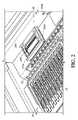
図2は、いくつかのサンプルチューブ32及び試薬ホルダ26を保持するラック24aと、受け入れトレイ520aにあるカートリッジ200とを示す診断装置10の内部図である。受け入れトレイ520aは、カバー28を取りつけた加熱器/光学モジュール500aから延びるあらゆる位置にある。受け入れトレイ520bは、閉じた位置にある。一部の実施形態において、受け入れトレイ520a、bは、ユーザによって又は自動装荷デバイスによってマイクロ流体カートリッジ200の簡単な配置を有利に可能にすることができる。かかる設計はまた、ロボット流体ディスペンサ400を使用してサンプルの多重化ピペットを収容することができる。 FIG. 2 is an internal view of the
受け入れトレイ
図2に示すように、凹部ベイ524は、マイクロ流体カートリッジ200を選択的に受け入れるように構成された受け入れトレイ520の一部分とすることができる。例えば、凹部ベイ524及びマイクロ流体カートリッジ200は、マイクロ流体カートリッジ200が、例えば、単一向きで選択的に受け入れられるように、相補的形状である縁部526を有することができる。例えば、マイクロ流体カートリッジ200は、ベイの相補的特徴に嵌合する位置合せ部材202を有することができる。位置合せ部材202は、例えば、側面の1つ又はそれよりも多くの上に作られたカートリッジ200の縁部上の切欠き部(図3Aに示すように)又は1つ又はそれよりも多くのノッチとすることができる。カートリッジと受け入れベイの間の相補性は、他の適切な配置、例えば、開口内に嵌合するポスト又は突起を使用して容易に達成することができることを当業者は容易に認めるであろう。選択的にカートリッジ200を受け入れることにより、光学モジュール502がカートリッジ200に対して適正に作動することができるように、受け入れベイ524は、ユーザがカートリッジ200を配置するのを助けることができる。このようにして、カートリッジ200の誤差無しアラインメントを達成することができる。Receiving Tray As shown in FIG. 2, the recessed
受け入れトレイ520は、マイクロ流体カートリッジ200に対して作動することができる装置の様々な構成要素(熱源、検出器、及び力部材など)がマイクロ流体カートリッジ200に対して適正に作動するように位置決めされ、同時にカートリッジ200が受け入れトレイ520の凹部ベイ524に受け入れられるように位置合せすることができる。例えば、受け入れトレイ520に受け入れられるマイクロ流体カートリッジ200上の異なる位置に熱源を熱的に結合することができるように、加熱器基板600上の接触熱源は、凹部ベイ524に位置付けることができる。 The receiving
マイクロ流体カートリッジ
ある一定の実施形態は、PCRなどによって1つ又はそれよりも多くのサンプルから1つ又はそれよりも多くのポリヌクレオチドの増幅を実施するように構成されたマイクロ流体カートリッジを考えている。カートリッジとは、全体的に又は部分的に使い捨て又は再利用可能にすることができるユニット、及びカートリッジを受け取ってカートリッジに対して作動するように(エネルギをカートリッジに配分するなど)適切にかつ相補的に構成された何らかの他の装置と共に使用するように構成することができるユニットを意味する。Microfluidic cartridges Certain embodiments contemplate microfluidic cartridges configured to perform amplification of one or more polynucleotides from one or more samples, such as by PCR. . A cartridge is a unit that can be made disposable or reusable in whole or in part, and appropriately and complementary to receive the cartridge and act on the cartridge (such as distributing energy to the cartridge). Means a unit that can be configured for use with any other device configured.
本明細書に使用される場合に、マイクロ流体とは、サンプル及び/又は試薬及び/又は増幅ポリヌクレオチドの容積が、上で定義したように1〜100μl又は2〜25μlのような約0.1μlから約999μlであることを意味する。同様に、カートリッジに適用する時の用語マイクロ流体は、本明細書で更に説明するようなカートリッジの様々な構成要素及びチャンネルが、サンプル、試薬、又は増幅ポリヌクレオチドのマイクロ流体容積の通路を受け入れ、及び/又は保持し、及び/又は容易にするように構成されることを意味する。本明細書のある一定の実施形態はまた、ナノリットル容積(100ナノリットルのような10〜500ナノリットルの範囲)で機能することができる。 As used herein, microfluidic means that the volume of sample and / or reagent and / or amplification polynucleotide is about 0.1 μl, such as 1-100 μl or 2-25 μl as defined above. To about 999 μl. Similarly, the term microfluidic when applied to a cartridge means that the various components and channels of the cartridge as described further herein accept a microfluidic volume passage of sample, reagent, or amplification polynucleotide, And / or is configured to be retained and / or facilitated. Certain embodiments herein can also function in nanoliter volumes (ranging from 10 to 500 nanoliters, such as 100 nanoliters).
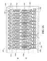
図3Aは、マイクロ流体カートリッジ200の上面図である。カートリッジ200は、複数のサンプルレーン1706a〜cを含むことができる。レーンは、カートリッジの「左」及び「右」側(すなわち、横列)に位置付けられたPCRチャンバ1703に至ることができる。図3aに示すように、レーンは、ユーザの近くの便利な位置に入口1705を設けることができる。しかし、ポートが接続されるレーンは、次に、独立経路を別々のチャンバ1703a〜cまでもたらすことができる。図3aの実施形態において、例えば、第1のレーン1706aは、左側の第1のチャンバ1703aと連通状態にあり、第2のレーン1706bは、右側の第1のチャンバ1703bと連通状態にあり、第3のレーン1706cは、左側の第2のチャンバ1703cと連通状態にある等々である。マイクロ流体レーンの各々はまた、マイクロ流体弁1702、1704、マイクロ流体ゲート、及びマイクロ流体チャンネルを含むことができる。これらのゲート及び弁は、例えば、熱作動により、カートリッジ200のレーン1706内の一部の流体の時間調節された放出及び制御された拡散を容易にするように構成することができる。この実施形態のカートリッジは、空気がカートリッジ内で流体通路を遮断するのを阻止する通気孔1701を含むことができる。弁のような様々なカートリッジ構成要素の更なる説明は、例えば、本明細書に引用により組み込まれている米国特許出願公開第2009−0130719号明細書に見出すことができる。 FIG. 3A is a top view of the
マイクロ流体カートリッジ200は、位置合せ部材202、例えば、切欠き部を含むことができ、切欠き部は、加熱器/光学モジュール500a、500bの受け入れトレイ520a、bの凹部ベイ524に相補的縁部を収容する。位置合せ部材202及び相補的縁部526は、受け入れトレイ520a、bにおけるマイクロ流体カートリッジ200の安全かつ正しい配置を可能にすることができる。 The
様々な実施形態において、カートリッジ200のサンプルレーン1706におけるマイクロ流体ネットワークの構成要素は、これらを加熱器基板600において加熱器と熱的に結合することによって加熱することができる。加熱器基板600は、増幅試薬及び増幅待機ポリヌクレオチドサンプルを含むサンプル混合物を加熱し、増幅待機サンプルからアンプリコンを生成するのに適する熱サイクル条件をサンプル混合物に受けさせるように構成することができる。加熱器基板600は、一部の実施形態においてカートリッジ200上に又は凹部ベイ524に位置付けることができる。 In various embodiments, the components of the microfluidic network in the sample lane 1706 of the
各レーンにおけるマイクロ流体ネットワークは、PCRなどにより、サンプルから抽出された核酸を含有するような増幅待機サンプルに対して核酸増幅を実施するように構成することができる。増幅待機サンプルは、増幅試薬及び抽出されたポリヌクレオチドサンプルの混合物を含むことができる。混合物は、熱サイクル条件を受けるのに適しており、抽出されたポリヌクレオチドサンプルからアンプリコンを生成することができる。例えば、PCR待機サンプルのような増幅待機サンプルは、ポリメラーゼ酵素と、陽性対照核酸と、陽性対照核酸及び複数のヌクレオチドの少なくとも一部分に対して選択性が高い蛍光発生雑種形成プローブと、ターゲットポリヌクレオチド配置に対していずれか少なくとも1つのプローブとを含むPCR試薬混合物を含むことができる。マイクロ流体ネットワークは、抽出されたポリヌクレオチドサンプルからPCRアンプリコンを生成するのに適する熱サイクル条件下で、外部熱源からの熱をPCR試薬及び抽出されたポリヌクレオチドサンプルを含む混合物と結合するように構成することができる。 The microfluidic network in each lane can be configured to perform nucleic acid amplification on an amplification standby sample that contains nucleic acid extracted from the sample, such as by PCR. The amplification standby sample can comprise a mixture of amplification reagents and extracted polynucleotide sample. The mixture is suitable to be subjected to thermal cycling conditions and can produce amplicons from the extracted polynucleotide sample. For example, an amplification waiting sample, such as a PCR waiting sample, includes a polymerase enzyme, a positive control nucleic acid, a positive control nucleic acid and a fluorogenic hybrid-forming probe that is highly selective for at least a portion of a plurality of nucleotides, and a target polynucleotide arrangement. A PCR reagent mixture comprising at least one probe. The microfluidic network combines heat from an external heat source with the mixture containing the PCR reagents and the extracted polynucleotide sample under thermal cycling conditions suitable for generating PCR amplicons from the extracted polynucleotide sample. Can be configured.
様々な実施形態において、試薬混合物は、望ましいアンプリコンの発生を検出するために蛍光又は他の光学的に検出可能なラベルを含むことができる。一部の実施形態において、複数のセットのプライマー及び複数のラベルは、多重分析フォーマット、例えば、多重PCRにおいて使用することができ、ここで、複数の異なるアンプリコンの各々は、存在する場合単一反応チャンバにおいて検出することができる。例えば、1つの分析チャンバは、試験サンプルからのテンプレート核酸、陽性対照テンプレート核酸、特定のターゲット配置の増幅のための1つ又はそれよりも多くのプライマー対、ターゲットアンプリコンの検出のための1つ又はそれよりも多くのプローブ、及び陽性対照アンプリコンの検出のための1つ又はそれよりも多くのプライマー対及びプローブを含むことができる。更に、一部の実施形態において、マイクロ流体カートリッジが、ターゲット又は陽性対照配置を増幅するのに使用するプライマー対によってアンプリコンを生成しない陰性対照ポリヌクレオチドを収容することを当業者は認めるであろう。 In various embodiments, the reagent mixture can include a fluorescent or other optically detectable label to detect the occurrence of the desired amplicon. In some embodiments, multiple sets of primers and multiple labels can be used in a multiplex analysis format, eg, multiplex PCR, where each of a plurality of different amplicons is a single when present. It can be detected in the reaction chamber. For example, one analysis chamber may comprise a template nucleic acid from a test sample, a positive control template nucleic acid, one or more primer pairs for amplification of a specific target configuration, one for detection of a target amplicon. Alternatively, more probes and one or more primer pairs and probes for detection of positive control amplicons can be included. Further, those skilled in the art will appreciate that in some embodiments, the microfluidic cartridge contains a negative control polynucleotide that does not produce an amplicon with the primer pair used to amplify the target or positive control arrangement. .
例示する実施形態のある一定のものにおいて、マルチレーンカートリッジ200の各レーン1706a〜cにそれぞれ関連付けられたチャンバ1703a〜cは、独立の増幅反応を実施することができる。第1の2つのレーン(1706a、1706b)に対するチャンバ(1703a、1703b)の第1の縦列の反応の結果は、次に、「左」及び「右」光源−光検出器対を含む検出器ヘッドを使用して同時に及び独立して測定することができる。すなわち、各レーン1706a〜bの各チャンバ1703a〜bは、個別の光源から光を受け入れることができ、個別の光検出器によって同時に観察することができる。このようにして、様々な組合せの反応を効率的にカートリッジにおいて実施することができる。例えば、一部の実施形態において、複数のターゲット核酸の検出のための複数の増幅分析は、1つのレーンでかつ陽性対照及び陰性対照を2つの他のレーンで、又はそれぞれ1つ又はそれよりも多くのターゲット核酸の検出のための1つ又はそれよりも多くの増幅分析を内部陽性対照と組み合わせて1つのレーンでかつ陰性対照を別のレーンで実施することができる。1つの特定の実施形態において、2、3、4、5、6、又はそれよりも多くの分析は、反応チャンバにおいて蛍光的に異なる燐光体の少なくともその数を有する単一レーンにおいて多重化される。 In certain of the illustrated embodiments,
マイクロ流体カートリッジ200は、いくつかの層から構成することができる。従って、本発明の技術の1つの態様は、第1、第2、第3、第4、及び第5の層を含むマイクロ流体カートリッジに関し、1つ又はそれよりも多くの層は、複数のマイクロ流体ネットワークを形成し、各ネットワークは、1つ又はそれよりも多くのポリヌクレオチドの有無が決定されることになるサンプルに対してPCRを実施するように構成された様々な構成要素を有する。別の実施形態において、マイクロ流体カートリッジ200は、複数のレンズを含むことができ、各々は、成形プラスチック基板などにおいて単一平面でエッチング又は成形された反応チャンバを含み、接着プラスチック塗膜層のようなカバー層により、各レーンを閉じる。1つのカートリッジ当たり8、10、12、14、16、18、20、22、24、28、30、又はそれよりも多くのレーンを有する実施形態が考えられている。例えば、1つの適切な設計は、任意的に比較的位置合せされた入口ポートを有する12の反応チャンバの2つの横列に配置された24の反応チャンバを有する単一カートリッジ200である。様々なカートリッジ及びこれらの構成要素の更なる説明は、例えば、本明細書に引用により組み込まれている米国特許出願公開第2008−0182301号明細書及び米国特許出願公開第2009−0130719号明細書に見出すことができる。 The
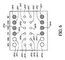
加熱器基板
図3Bに示されているのは、加熱器基板600の一部の実施形態の上面図である。受動又は能動冷却のいずれかが企図された抵抗、ペルチェ、又は移動流体加熱器を含むあらゆるタイプの加熱器を使用することができる。多くの可能な実施形態のうちの1つは、各反応チャンバと熱的に接触した複数の抵抗加熱器を含み、好ましくは1つ又はそれよりも多くの温度センサも含む。抵抗加熱器はまた、何らかのサーミスタ効果、すなわち、温度によるこれらの抵抗変化を示すので、抵抗加熱器自体は、製品設計を簡素化しながら各反応チャンバの正確な温度制御を容易にする。加熱器は、互いに協調して制御することができるが、一部の実施形態において、加熱器は個別に制御可能であり、各反応チャンバが加熱されて他の反応チャンバとは独立して冷却することを容易にすることができるように、各反応チャンバは、それと熱的に接触した1つ又はそれよりも多くの個々の加熱器を有することができる。それは、複数の反応チャンバの各々において異なる分析を同時に実施することを容易にする。個々の反応チャンバと共に使用するための1つの特定の抵抗加熱器アセンブリが図3Bに示されている。図3Bに示す実施形態において、上部センサ加熱器/センサ1604、底部加熱器/センサ1603、側部加熱器/センサ1601、及び中心加熱器/センサ1602のあらゆる組合せを使用して、その上に位置する反応チャンバを加熱することができる。理解しやすくするために、一部の実施形態のPCRチャンバ1703の外形は、加熱器基板上に重ねられている。一部の実施形態において、加熱器基板600の加熱器は、加熱器と接触する場合がある。かかる接触加熱器は、(例えば、)抵抗加熱器(又はそのネットワーク)、ラジエータ、流体熱交換器、及びペルチェデバイスを含むことができる。接触熱源は、凹部ベイ524に構成され、受け入れトレイ520a、bに受け入れるマイクロ流体カートリッジの1つ又はそれよりも多くの異なる位置に熱的に結合することができ、それによって異なる位置は、選択的に加熱される。接触熱源は、加熱器基板600において構成され、受け入れトレイ520a、bに受け入れるマイクロ流体カートリッジ200の異なる位置に独立に熱的に結合することができ、それによって異なる位置は、独立に加熱される。接触熱源は、受け入れトレイ520a、bに受け入れるマイクロ流体カートリッジ200の異なる位置と直接物理的接触状態になるように構成することができる。様々な実施形態において、各接触源加熱器は、約1ミリメートル(mm)から約15mm(典型的には、約1mmから約10mm)の2次元の平均直径を有する異なる位置、又は約1ミリメートルから約225mm(一部の実施形態において、約1mmから約100mm、又は一部の実施形態において、約5mmから約50mm)の表面積を有する異なる位置を加熱するように構成することができる。Heater Substrate FIG. 3B shows a top view of some embodiments of the
加熱器基板600は、カートリッジ200のレーン1706a〜cの構造と平行な「レーン」1605aに編成することができる。一部の実施形態において、加熱器基板600は、カートリッジ200のサンプルレーン1706に対応する24の加熱器レーン1605a、1605bを含むことができる。マイクロ流体カートリッジ200が、受け入れトレイ520a、bの凹部ベイ524に配置される時に、カートリッジ200の構成要素は、加熱器基板600の対応する加熱器に隣接して及びその上に位置合せすることができる。マイクロ流体カートリッジ200が凹部ベイ524に配置される時に、加熱器は、それぞれの構成要素と物理的に接触することができる。一部の実施形態において、加熱器は、これらのそれぞれの構成要素に、例えば、直接物理的接触状態ではないが1つ又はそれよりも多くの中間層又は材料を通じて熱的に結合したままである。レーンの更なる説明は、本明細書に引用により組み込まれている米国特許出願公開第2009−0130719号明細書に見出すことができる。 The
一部の実施形態において、複数の加熱器は、同時かつ均一に作動してマイクロ流体カートリッジ200においてマイクロ流体ネットワークのこれらのそれぞれの隣接するカートリッジ構成要素を加熱するように構成することができる。各加熱器は、本明細書に説明する装置と共に使用するプロセッサ及び/又は制御回路によって独立に制御することができる。一般的に、マイクロ流体カートリッジ200におけるマイクロ流体構成要素(ゲート、弁、チャンバ、その他)の加熱は、好ましく構成された微細加工加熱器に電流を通すことによって制御される。適切な回路の制御の下で、マルチレーンカートリッジのレーン1706は、次に、独立に加熱することができ、それによって互いに独立に制御することができる。更に、後でより詳細に説明するように、個々の加熱器1601〜1604は、互いに独立して加熱することができ、それによって互いに独立に制御することができる。これは、全ての加熱器が同時に加熱されているとは限らず、所定の加熱器を加熱する必要がある時にだけ少しの時間にわたって電流を受け取るので、装置のより大きなエネルギ効率及び制御をもたらすことができる。 In some embodiments, the plurality of heaters can be configured to operate simultaneously and uniformly to heat their respective adjacent cartridge components of the microfluidic network in the
加熱器基板600はまた、1つ又はそれよりも多くの加熱器センサを含むことができる。加熱器レーン1605a、1605bにおいて加熱器を制御する必要があるセンサ又は加熱器の数を低減するために、加熱器を使用して温度及び熱を検知することができ、それによって互いに個別の専用センサを有する必要性を取り除く。例えば、一部の材料のインピーダンス及び/又は抵抗は、周囲の温度と共に変化する。従って、加熱器/センサ1601〜1604の抵抗は、センサが能動的に加熱されていない時の温度の指標として使用することができる。 The
一部の実施形態において、加熱器基板600内の加熱器は、十分なワット数を有するように設計され、電気的に制御可能な要素の数を低減し、それによって関連の電子回路への負担を低減するために直列又は並列に加熱器をグループ分けすることを容易にすることができる。このようにして互いにグループ分けされた加熱器は、同期して実質的に同時制御の下で作動すると考えられる。 In some embodiments, the heaters in the
一部の実施形態において、第2ステージ加熱器の両側の反応チャンバ加熱器は、同期制御の下で作動するようにグループ分け及び構成することができる。例えば、一部の実施形態において、PCR/増幅加熱器1601〜1602は、同期制御の下で作動するようにグループ分け及び構成することができる。代替のグループ分け及び構成は、PCR/増幅加熱器1601〜1604の他の加熱器グループに適用することができる。PCR/増幅加熱器1601〜1604は、個々にかつ独立に作動するように構成することができ、又はこれらは、2つ(対)、3つ(サード)、4つ、5つ、又は6つのグループで作動するように構成することができる。 In some embodiments, the reaction chamber heaters on either side of the second stage heater can be grouped and configured to operate under synchronous control. For example, in some embodiments, PCR / amplification heaters 1601-1602 can be grouped and configured to operate under synchronous control. Alternative groupings and configurations can be applied to other heater groups of PCR / amplification heaters 1601-1604. The PCR / amplification heaters 1601-1604 can be configured to operate individually and independently, or they can be two (paired), three (third), four, five, or six Can be configured to operate in groups.
一部の実施形態において、加熱は、様々なパルス幅変調(PWM)を有するそれぞれの加熱器に対して定期的に電流をオン及びオフにすることによって制御することができ、パルス幅変調は、電流のオン時間/オフ時間比を意味する。電流は、微細加工加熱器を高電圧供給源(例えば、30V)に接続することによって供給することができ、高電圧供給源は、PWM(パルス幅変調)信号によってゲート制御することができる。一部の実施形態において、デバイスは、48のPWM(パルス幅変調)信号発生器を含むことができる。一部の実施形態において、各反応チャンバに関連付けられた2つのPWM(パルス幅変調)信号発生器が存在することになる。PWM(パルス幅変調)発生器の作動は、選択されたプログラマブル期間(終了カウント)及び粒度による信号の発生を含むことができる。例えば、信号は、1us(マイクロ秒)の粒度を有する4000usとすることができ、その場合には、PWM(パルス幅変調)発生器は、信号がゼロに戻る時にゼロで始まり、信号が4000usに到達するまで1usの増分で進行してカウンタを維持することができる。従って、生成される熱の量は、終了カウントを調節することによって調節することができる。高い終了カウントは、微細加工加熱器が電流を受け入れるよりも長い時間の長さ、及び従って生成されるより大量の熱に対応する。 In some embodiments, heating can be controlled by periodically turning the current on and off for each heater having various pulse width modulations (PWM), It means the current on-time / off-time ratio. The current can be supplied by connecting a microfabricated heater to a high voltage supply (eg, 30V), which can be gated by a PWM (pulse width modulation) signal. In some embodiments, the device may include 48 PWM (pulse width modulation) signal generators. In some embodiments, there will be two PWM (pulse width modulation) signal generators associated with each reaction chamber. The operation of the PWM (Pulse Width Modulation) generator can include the generation of a signal with a selected programmable period (end count) and granularity. For example, the signal can be 4000 us with a granularity of 1 us (microseconds), in which case the PWM (pulse width modulation) generator starts at zero when the signal returns to zero and the signal goes to 4000 us. It can proceed in 1us increments until the counter is maintained. Thus, the amount of heat generated can be adjusted by adjusting the end count. A high end count corresponds to a longer length of time than the microfabricated heater accepts the current, and thus a greater amount of heat generated.
様々な実施形態において、PWM(パルス幅変調)発生器の作動はまた、上述の終了カウント及び粒度に加えてプログラマブル開始カウントを含むことができる。かかる実施形態において、複数のPWM(パルス幅変調)発生器は、高圧電力の電流容量が超過しないように、選択的に重ならない信号を生成することができる(例えば、様々な加熱器のオン時間を多重化することにより)。 In various embodiments, the operation of a PWM (pulse width modulation) generator can also include a programmable start count in addition to the end count and granularity described above. In such embodiments, multiple PWM (pulse width modulation) generators can generate signals that do not overlap selectively so that the current capacity of the high voltage power is not exceeded (eg, various heater on-times). By multiplexing).
複数の加熱器は、様々な開始及び終了カウントを有する異なるPWM(パルス幅変調)信号発生器によって制御することができる。加熱器は、バンクに分けることができ、それによってバンクは、同じ開始カウントの加熱器のグループを定める。加熱要素及びある一定の実施形態において存在する場合に冷却要素の制御は、後でより詳細に説明する。 Multiple heaters can be controlled by different PWM (pulse width modulation) signal generators with different start and end counts. The heaters can be divided into banks, whereby the banks define a group of heaters with the same starting count. Control of the heating element and the cooling element if present in certain embodiments will be described in more detail later.
光学モジュール
図4A〜図4Cは、ある一定の実施形態に見出される検出装置10の加熱器/光学モジュール500を示している。加熱器/光学モジュール500は、光学モジュール502及び受け入れトレイ520又は受け入れトレイの一部分を含むことができる。図4Aは、検出器ヘッド700の移動を駆動するためにその外部に取りつけられたモータ504を有する封入光学モジュール502の一実施形態を示している。検出器ヘッド700は、光学モジュール502の内側に収容することができる。図4Aは、光学モジュール502の下部506に結合された受け入れトレイ520を示している。受け入れトレイ520は、検出を実施すべきサンプルを含むカートリッジ200を受け入れることができる。サンプルを受け入れた後に、受け入れトレイ520は、光学モジュール502の下のある一定の位置までレール522で移動することができる(例えば、機械的に又は手動で)。後でより詳細に説明する一部の実施形態において、受け入れトレイは、自動装填デバイスを含むことができ、自動装填デバイスは、光学モジュール502の下に位置決めされる時にカートリッジを自動的に位置合せする。一部の実施形態において、受け入れトレイ520の受け入れベイ524は、加熱器基板600を収容することができる。一部の実施形態において、受け入れトレイは、その後に隆起して、光学モジュール502の基部にある開口プレート540と接触するなどで光学モジュール502と接触状態にカートリッジを配置することができる。Optical Module FIGS. 4A-4C illustrate the heater /
図4Bは、光学モジュール502の内部を示すように前部パネル508が取り外された光学モジュール502の実施形態を示している。図4Bに示されているのは、検出器ヘッド700である。後で詳細に説明するように、検出器ヘッド700の移動は、モータ504によって駆動されて光学モジュール502内を横切って横方向に移動させ、カートリッジ200が受け入れトレイ520において光学モジュール502の下に位置決めされる時にカートリッジ200上で光学式走査及び検出を行うことを可能にする。図4Bに示されているのは、光学モジュール502の下部506上に位置決めされた開口プレート540である。 FIG. 4B shows an embodiment of the
図4Cは、光学モジュール502の底平面図を与える。図4Cに示されているのは、光学モジュール502の下部506に取りつけられた開口プレート540及び正規化プレート546である。正規化プレートを使用して、検出器ヘッドの光源−光検出器対を較正することができる。正規化プレート546は、好ましくは、既知の標準光学特性を有する1つ又はそれよりも多くの構成要素を含み、検出器ヘッド700及び関連回路の適切な作動を較正、標準化、又は確認するように構成される。正規化プレート546は、光学モジュールの中に延びることができ、検出器ヘッド700は、正規化プレートの上に位置付けることができる。一部の実施形態において、カートリッジ光学的測定の開始前に、検出器ヘッド700は、正規化プレート546の既知の特性を使用して較正される。検出器ヘッド700が適正に働いていない場合に、測定におけるオフセット又はユーザへのエラーの通知などを含む修正措置を取ることができる。一部の実施形態において、正規化プレートは、高蛍光色素又は他の標準発色団又は燐光体と混合したポリカーボネートのような光学透明材料で作ることができる。一実施形態において、正規化プレートは、検出器ヘッド700の各チャンネル又はカラーに対する標準発色団又は燐光体を含む。 FIG. 4C provides a bottom plan view of the
図4Cに示すように、開口プレート540は、開口557を収容する。開口557の寸法は、検出器が光学モジュール502内の複数の位置に移動する時に、検出器の光源及び光検出器が、カートリッジ200の反応チャンバの内容物にアクセスする(光学的に励起するか又は見る)ことができるようなものである。すなわち、検出器の光源−光検出器対が、特定の開口の上のある一定の位置に位置する時に、光は、光源から進んで開口557を通してチャンバリアクタに到達することができる。反応チャンバ中の蛍光試薬は、次に、開口557を通じて光検出器で見ることができる。 As shown in FIG. 4C, the opening
検出器ヘッド
図5は、図4Bの線13に沿って取った検出器ヘッド700の断面を示している。検出器ヘッド700は、反応チャンバ1703に存在する1つ又はそれよりも多くのポリヌクレオチドからの検出に関連して放出する蛍光を光学的に励起及び/又はモニタするように構成することができる。肯定的な結果(ターゲットアンプリコンの存在)は、分析設計に応じて蛍光の増加又は蛍光の減少によって示すことができることに注意すべきである。例えば、分析が、燐光体及び消光剤を伴う時に、消光剤は、ターゲットが存在する時に又は他の分析設計においてターゲットが存在しない時に蛍光を消光することができる。システムは、例えば、複数の検出器対、例えば、検出器対726のような3、4、5、6、7、8、9、10、11、12、13、14、15、16、17、18、19、20、21、22、23、24、又はそれよりも多くのものを含むことができる。各検出器対726は、発光ダイオード(LED)のような光源726aと光ダイオードのような対応する光検出器726bとで構成することができる。光源726aは、蛍光プローブの吸収帯において選択的に光を放出することができる。光検出器726bは、蛍光プローブの放出帯において選択的に光を検出することができ、蛍光プローブは、ポリヌクレオチドプローブ又はその断片に対応する。ある一定の実施形態において、光源726bは、蛍光プローブの吸収帯において選択的に光を放出する帯域通過フィルタダイオードを含むことができる。光検出器726bは、蛍光部分の放出帯における光、例えば、蛍光プローブからの放出を選択的に検出する帯域通過フィルタ光ダイオードを含むことができる。ある一定の実施形態において、帯域通過フィルタのようなフィルタ726alは、光源726aの光に適用することができる。光源726aからの光は、マイクロ流体チャンネルにおいてサンプルを通過する前にフィルタを通過する(ある一定の実施形態において300gの深さ)。ある一定の実施形態において、反応チャンバから光検出器726bまでの光の光路長は、非常に短くすることができる。光源726aからの入射光は、反応チャンバにおいて蛍光を発生させる。反応チャンバからの光は、次に、光検出器726bに移動する。一部の実施形態は、あらゆる望ましくない光が検出器に入るのを軽減しようとし、それによって反応チャンバからの光信号に悪影響を与える。Detector Head FIG. 5 shows a cross section of
一部の実施形態において、複数の検出器対の各々は、横列の検出器ヘッド700の長さに沿って配置することができる。すなわち、図5に示す対726及び727の後側は、類似か又は同じ向きの対の別の縦列とすることができる。説明のために、カートリッジの長さに沿ったカートリッジ又は検出器対の集合は、「横列」と呼ばれ、カートリッジの幅に沿ったカートリッジ又は検出器対の集合は、「縦列」と呼ばれる。従って、図3A及び図6の垂直方向は「縦列」を示し、水平方向は「横列」を示す。ある一定の実施形態は、かかる検出器対の6つ又はそれよりも多くの縦列を考えている。これらの実施形態において、12の個別かつ同時の検出を可能にする縦列当たり2つの検出対を有する合計12の検出対(6つの2横列)が存在すると考えられる。 In some embodiments, each of the plurality of detector pairs can be disposed along the length of a row of detector heads 700. That is, the back side of
例えば、光源726aのような各光源は、例えば、反応チャンバに収容されたプローブに関連付けられた特定の蛍光部分に特有である波長の長さを生成するように構成することができる。例えば、726bのような各検出器は、検出器対において発光体によって生成する光に関連付けられた蛍光プローブから放出する光を検出するように構成することができる。検出器対は、複数の蛍光部分、例えば、異なる蛍光放出スペクトルを有する異なる蛍光プローブを独立に検出するように構成することができ、各反応チャンバにおいて、各蛍光プローブからの放出は、1つの特定のターゲットポリヌクレオチド又はその断片の有無を示している。折り返し光路を使用することができるが、一実施形態は、各々が反応チャンバと直接光接触状態にあり、好ましくはかかる接触において同時である検出器及び発光体対を利用する。任意的に、対の検出器及び発光体は、反応チャンバにおいて鋭角で実質的に交差する線に沿って反応チャンバに位置合せされる。角度は、例えば、約5から70度、好ましくは、約8から60度、より好ましくは、約10から50度とすることができる。 For example, each light source, such as
一部の実施形態において、検出器ヘッドは、装置に存在する時に、マイクロ流体カートリッジの反応チャンバの2つの横列に対応する2つの横列の光検出器及び光源対を含む。例えば、検出器ヘッドは、第1又は上部横列の6つの光検出器及び光源対、及び第2又は下部横列の光検出器及び光源対を含むことができ、これらは、それぞれマイクロ流体カートリッジ内に第1及び第2の横列の反応チャンバを消光するように構成される。 In some embodiments, the detector head includes two rows of photodetectors and light source pairs that, when present in the device, correspond to the two rows of the reaction chamber of the microfluidic cartridge. For example, the detector head can include six photodetectors and light source pairs in a first or upper row, and a second detector and light source pair in a second or lower row, each in a microfluidic cartridge. The first and second rows of reaction chambers are configured to be quenched.
図6は、検出器の一部の実施形態に実施される1つの可能な光検出器及び光源レイアウトを示している。第1の縦列は、ROX発光体201a、201b及び対応する検出器207a、207bを含む。第2の縦列は、HRM発光体201c、201d及び対応する検出器207c、207dを含む。第3の縦列は、CY5発光体201e、201f及び対応する検出器207e、207fを含む。第4の縦列は、FAM発光体201g、201h及び対応する検出器207g、207hを含む。第5の縦列は、Q705発光体201i、201j及び対応する検出器207i、207jを含む。第6の縦列は、VIC発光体201k、201l及び対応する検出器207k、207lを含む。一部の事例において、検出器及び発光体は、分析において使用すべき特定の燐光体に関連して選択される。図6に示す実施形態において、第1の又は上部横列検出器及び光源対は、複数の光検出器及び光源対、例えば、発光体201a、201c、201e、201g、201i、及び201k、並びに検出器207a、207c、207e、207g、207i、及び207kを含む。第2又は下部横列検出器及び光源対は、複数の光検出器及び光源対、例えば、発光体201b、201d、201f、201h、201j、及び201l、並びに検出器207b、207d、207f、207h、207j、及び207lを含む。例示的な発光体及び検出器の特性の要約は、以下の表1に示されている。 FIG. 6 illustrates one possible photodetector and light source layout implemented in some embodiments of the detector. The first column includes ROX emitters 201a, 201b and corresponding detectors 207a, 207b. The second column includes HRM emitters 201c, 201d and
(表1)
図6に示す光検出器及び光源の例示的な配置は、検出縦列の間のクロストークを抑制することができる。すなわち、各発光体検出器対に対する波長範囲は、その隣接する発光体−検出器対との最小の重なりを保有するように選択することができる。従って、例えば、CT#が6縦列検出器ヘッドにおいて特定の発光体−検出器対の縦列を意味する場合、Exは燐光体の励起波長であり、Emは放出波長であり、隣接する放出波長は、検出器ヘッドにおいては互いに隣接していないことは明らかであろう。横列HRMの色素がヌルであることは、単にこの特定の例に必要のない様々な色素を使用することができることを示すに過ぎない。一部の実施形態において、HRMは、「高解像度融解」を意味し、この光検出器の対応する光源は、紫外線スペクトルにおいて作動するLEDを含むことができる。縦列は、代替の変形に配置することができ、光源及び検出器の代替の選択は、図示のものによって置換することができることは認識されるであろう。 The exemplary arrangement of photodetectors and light sources shown in FIG. 6 can suppress crosstalk between detection columns. That is, the wavelength range for each illuminant detector pair can be selected to possess a minimum overlap with its adjacent illuminant-detector pair. Thus, for example, if CT # means a specific emitter-detector pair column in a 6 column detector head, Ex is the phosphor excitation wavelength, Em is the emission wavelength, and the adjacent emission wavelength is It will be clear that the detector heads are not adjacent to each other. The fact that the dye in the row HRM is null merely indicates that a variety of dyes not needed for this particular example can be used. In some embodiments, HRM means “high resolution melting” and the corresponding light source of the photodetector can include an LED operating in the ultraviolet spectrum. It will be appreciated that the columns can be arranged in alternative variations and that alternative choices of light sources and detectors can be substituted by those shown.
各縦列の発光体及び光検出器対は、正規化プレートを使用して較正することができる。較正後、検出器ヘッドは、各発光体及び光検出器対がレーンの反応チャンバへのアクセスを有するように、第1の縦列の発光体及び光検出器対が第1のグループのレーンの上に位置付けられるような位置に移動することができる。第1のグループのレーンにおける反応チャンバの検出は、次に、第1の縦列の発光体/検出器を使用して実施されることになる。次に、検出器ヘッドは、第1の縦列が第2のグループのレーンの上にあり、第2の縦列が第1のグループのレーンの上にあるように第2の位置に移動することができる。第2のグループのレーンにおける反応チャンバの検出は、次に、第1の縦列の発光体/検出器を使用して実施されることになり、第1のグループのレーンにおける反応チャンバの検出は、次に、第2の縦列の発光体/検出器を使用して実施されることになる。処理は、各縦列が各レーンの上を通過するまで続けることができる。従って、N縦列の検出器及びM縦列のチャンバに対して、検出器は、少なくともM+N−1位置で検出を実施することになる。例えば、図11の実施形態において6つの縦列がある。12のレーンを含むカートリッジに対して、検出器は、少なくとも17の位置(較正位置を考慮する場合は18)の間で移動する必要があると考えられる。 Each column of emitter and photodetector pairs can be calibrated using a normalization plate. After calibration, the detector head is configured so that the first column of emitter and photodetector pairs are above the first group of lanes so that each emitter and photodetector pair has access to the reaction chamber of the lane. Can be moved to a position such that Detection of reaction chambers in the first group of lanes will then be performed using a first column of illuminators / detectors. The detector head may then be moved to a second position so that the first column is above the second group of lanes and the second column is above the first group of lanes. it can. Detection of reaction chambers in the second group of lanes will then be performed using a first column of illuminators / detectors, and detection of reaction chambers in the first group of lanes is: It will then be implemented using a second column of illuminators / detectors. The process can continue until each column passes over each lane. Thus, for N column detectors and M column chambers, the detector will perform detection at least at the M + N-1 position. For example, there are six columns in the embodiment of FIG. For a cartridge containing 12 lanes, the detector would need to move between at least 17 positions (18 when considering the calibration position).
図7は、実施形態のある一定のものの作動後の最終結果を示している。プロットされているのは、単一レーンに関連付けられた単一反応チャンバ(又はリアクタ)に対して時間と共に各発光体−光検出器対801〜805に関して検出された蛍光レベルである。焼きなまし及び変性プロトコルの十分な数の反復後に(この例において約30)、検出器は、リアクタ内の蛍光の増加するレベルを識別する。 FIG. 7 shows the final result after activation of certain embodiments. Plotted are the fluorescence levels detected for each emitter-photodetector pair 801-805 over time for a single reaction chamber (or reactor) associated with a single lane. After a sufficient number of iterations of the annealing and denaturing protocol (about 30 in this example), the detector identifies increasing levels of fluorescence in the reactor.
チャンバプレート
本発明の実施形態のある一定のものは、チャンバ層を取り囲み、かつそれを含む焼き付けに関する。特に、ある一定の実施形態は、後でより詳細に説明するように、加熱/検出モジュールの試行にわたって一貫した結果を有利に容易にする特性を含む開口層の製造を考えている。Chamber Plate Certain embodiments of the invention relate to baking that surrounds and includes a chamber layer. In particular, certain embodiments contemplate the manufacture of an aperture layer that includes properties that advantageously facilitate consistent results across trials of the heating / detection module, as will be described in more detail later.
図8は、走査熱サイクラーの光学モジュール、並びに関連付けられた受け入れトレイ及びカートリッジのある一定の実施形態に見出される焼き付け配置を示している。光学モジュール500aの開口層540の近くにカートリッジがもたらされる時に、温度層600、チャンバ層200(これは、チャンバ基板を含むことができる)、及び開口層540は、図8の実施形態において示したように位置付けることができる。上述したように、チャンバ層200は、複数の反応チャンバ1703a〜dを含むことができ、反応チャンバ1703a〜dは、互いに個別に又はグループで熱的に制御するように位置決めすることができる。温度層600は、複数の熱ユニット1605a、1605b、1605cを含むことができる。図8は、上記説明の簡素化された抽象図であり、マイクロ流路の一部の特徴は示されていない。一部の実施形態において、熱ユニットは、機械的及び熱的の両方で互いに切断することができる(図4にこれらの物理的分離によって示すように)。しかし、他の実施形態において、熱ユニットは、上述したように、同じ基板材料内に各々配置することができるが、これらが熱的に切断されたままであるように離間させることができる。従って、熱ユニットを熱的に分離することはできるが機械的に分離することはできない。 FIG. 8 shows the printing arrangement found in certain embodiments of the optical module of the scanning thermal cycler and the associated receiving tray and cartridge. When the cartridge is brought near the
このようにして、各熱ユニットは、残りの反応チャンバから別々に1つ又はそれよりも多くの反応チャンバ1703a〜dに関連付けることができる。各反応チャンバに対して指定されたプロトコルに従って、熱ユニットは、確実にこれらの対応するチャンバを適正に加熱及び/又は冷却することができる。例えば、熱ユニット1605cは、チャンバ1703aの温度が実質的にチャンバ1703aの冷却及び熱状態とは無関係であるようにチャンバ1703aを冷却及び/又は加熱することができる。加熱は、電流がマイクロ流体又は電子回路を通過することによって達成することができるが、冷却は、マイクロ流体チャンバ間の対流のみを使用してチャンバの温度を低下させるという点で「受動的」とすることができる。熱ユニット1605a、1605b、1605cは、閉ループ制御システムを使用して制御することができる。 In this way, each thermal unit can be associated with one or
一部の実施形態において、開口プレート540は、チャンバ層200の上に位置付けることができ、かつ温度層600によってマイクロ流体カートリッジ、例えば、チャンバ層の加熱及び冷却を容易にするためにチャンバ層200に圧力を与えることができる。開口プレートは、複数の開口557a〜dを含み、個々の反応チャンバ1703a〜dの各光検出器726bの観察を容易にすることができる。開口プレート540がない場合かつ温度層600及びチャンバ層200の構成に応じて、チャンバ層200は、「反り」及び/又は十分に可撓性である場合があり、チャンバとそれぞれの熱ユニットの間の熱伝達は非一貫性である。非一貫性の加熱及び冷却は、プロトコルの精度の低い実行及びあまり正確でない精度の低い結果をもたらす可能性がある。上述したように、有意な反りは、光学ヘッドを横方向移動から制限する場合がある。従って、開口プレートの厚みを適正に選択して、チャンバ層の適切な加熱及び冷却を依然として確実にしながら、各反応チャンバと光源及び光検出器の間の適切な光路を可能にしなければならない。開口層が厚すぎる場合に、光検出器726bからチャンバまでの距離は大きすぎる場合があり、反応チャンバからの蛍光読取を減衰するので望ましくない。反応チャンバまでの距離を増加させるのに加えて、厚すぎる又は重過ぎる開口層540は、反応チャンバに対して過剰な圧力を課すことになり、対流を大きくし過ぎる。反対に、開口層540が薄すぎる場合に、開口層540は、チャンバ層200が曲がって反るのを阻止することができず、開口層540自体が曲がって反る場合がある。開口557a〜d又はチャンバ1703a〜dの反りは、光源726aからの光を偏向し、光検出器726bによる正確な読取を阻止する場合がある。 In some embodiments, the
従って、本明細書に説明する実施形態は、上述の欠点を有利に回避する開口層を与える。ある一定の実施形態において、開口層540は、少なくとも部分的に鋼で作られる。これらの実施形態において、鋼は、作動に対して望ましい適切な強度、密度、及び撓みに対する抵抗を与える。更に、鋼は、低自家蛍光を与えることができ、従って、光検出器726bの読取に悪影響を与える可能性が低い。鋼はまた、電気化学的に処理され、鋼の自家蛍光を低下させ、それによって光検出器の読取に悪影響を与える可能性が低い。ある一定の実施形態において、開口層は、その代わりに黒ニッケル(Ni)、すなわち、自家蛍光を低下させるために黒ニッケルに加えられる着色剤を有するNiを含むことができる。ある一定の実施形態は、これらの異なる材料及び電気化学処理の組合せを考えている。ある一定の実施形態において、開口層540は、アルミニウムで作られ、隣接する支持パネル500、506、及び546によって固定される時に適切な強度を与える。アルミニウムは、陽極酸化仕上げを用いて、例えば、自家蛍光を低下させるために加える黒色着色剤を用いて電気化学的に焼き付けることができる。 Accordingly, the embodiments described herein provide an aperture layer that advantageously avoids the above-mentioned drawbacks. In certain embodiments, the
照明光学系は、反応チャンバ又はリアクタの上に落ちる励起光がリアクタの形状に類似している領域に沿って入射するように設計することができる。リアクタは長くかつ狭くすることができ、照明スポットも、長くかつ狭く、すなわち、延長することができる。従って、開口557a〜dの形状は、反応チャンバの下の寸法、並びに対応する発光体及び光検出器の相対位置の両方に対して配慮して設計することができる。スポットの長さは、光検出器726bを配置するボア(フィルタ及びレンズを保持するチューブは、開口形成効果を有することができる)の直径と、PCRリアクタからの光検出器726bの距離と、光検出器726bにおける適切なレンズの使用とを含むいくつかのファクタを変更することによって調節することができる。 The illumination optics can be designed so that the excitation light falling on the reaction chamber or reactor is incident along a region that resembles the shape of the reactor. The reactor can be long and narrow, and the illumination spot can also be long and narrow, i.e. extended. Accordingly, the shape of the openings 557a-d can be designed with consideration for both the dimensions under the reaction chamber and the relative positions of the corresponding emitters and photodetectors. The length of the spot is the diameter of the bore where the photodetector 726b is placed (the tube holding the filter and lens can have an opening-forming effect), the distance of the photodetector 726b from the PCR reactor, and the light Adjustments can be made by changing several factors, including the use of an appropriate lens in detector 726b.
力部材
ある一定の実施形態において、受け入れトレイ520は、チャンバ層200を温度層600又は開口層540の近くに配置するが、機械的に結合せず、及び/又はそれによって層を互いに接触状態に配置しない。このようにして、チャンバ層200は、熱的であるが機械的でなく温度層600に結合することができる。他の実施形態において、受け入れトレイは、温度層600をチャンバ層200と機械的及び熱的接触したその両方で、かつチャンバ層を開口層540と機械的接触状態で配置する。様々な実施形態において、開口は、受け入れトレイ520に位置決めされたマイクロ流体カートリッジ200に熱源を熱的に結合するために圧力を受け入れトレイ520に印加するように構成された1つ又はそれよりも多くの力部材(図示せず)を含むことができる。圧力の印加は、マイクロ流体カートリッジ200において加熱器基板と反応チャンバ、ゲート、及び弁などとの間で一貫した熱的接触を確実するのに重要である場合がある。受け入れトレイ520がそれによって光学モジュール502の開口プレート540の下に位置決めされる閉鎖位置の時に、受け入れトレイ520の下のモータアセンブリのような力部材は、光学モジュール502の方向に上方に移動し始め、それによって受け入れトレイ520を光学モジュール502に近づけることができる。受け入れトレイ520が光学モジュール502の方向に上方に移動すると、カートリッジ200は、開口プレート540の下部と接触状態になり始めることができる。カートリッジ200は、十分な圧力をカートリッジ200が受けるまで上方に移動し続けることができる。上述したように、開口プレート540は、カートリッジ200の上部の全ての点にわたって等しい圧力を印加し、従って、均一な圧力で加熱器基板600に対してカートリッジ200を押圧することができる。上述したように、開口層は、この作動を容易にする特性を保有するように選択することができる。例えば、開口プレート540の材料選択は、それに対して押圧する時にカートリッジ200の撓みが殆どないようにすることができる。Force Member In certain embodiments, the receiving
加熱器基板600に対するカートリッジ200の均一な圧力の印加は、望ましい時はカートリッジの構成要素の各々に対して均一な加熱を可能にすることができる。均一な圧力及び接触は、加熱器基板600における加熱器とカートリッジ200におけるマイクロ流体ネットワークの構成要素(弁、ゲート、チャンバ、その他)の間で得ることができるが、加熱器は、必ずしも上述したように同時に開始する必要はない。一部の実施形態において、均一な圧力の印加は、必ずしもカートリッジ200の異なる構成要素の等しい加熱をもたらさない。一部の実施形態において、開口プレート540によってカートリッジ200に印加される圧力と共に加熱器基板600における特定の加熱器の作動の両方は、カートリッジ200の特定の構成要素を作動する。 Application of a uniform pressure of the
図9A〜図9Hは、開口プレートの1つの可能な実施形態の寸法の図である。この実施形態において、化学変換被覆は、開口層の反射特性を調節するように付加することができる。いくつかの部分9002は、化学変換被覆を受け入れないように選択することができる。コーティングは、プレート540の表面に付加するか又はその材料を通して堆積させることができる。一部の実施形態において、プレート540の材料は、鋼を含むことができる。他の実施形態において、プレート540は、アルミニウムを含むことができる。更に他の実施形態において、プレート540の材料は、ニッケルを含むことができる。一部の実施形態において、プレートの材料は、例えば、アルミニウム、ニッケル、又は鋼を含む2つ又はそれよりも多くの材料の組合せとすることができる。 9A-9H are dimensional illustrations of one possible embodiment of an aperture plate. In this embodiment, a chemical conversion coating can be added to adjust the reflective properties of the aperture layer. Some
図9A〜図9Hに示す実施形態において、プレートの寸法は、チャンバ圧力及び光路に関する制約を上述の検出器対に適合させるように選択される。プレート540の材料厚みは、0.3125インチで始め、望ましい厚みまで機械切削される。示すように、プレートの多くは、約0.25インチの厚みを含む。しかし、この厚みは、異なる場合があり、例えば、開口の開口部557にわたる厚みは、0.19インチとすることができる。上述したように、開口の開口部の厚みは、反応チャンバの内容物に対して光検出器と光源の間の滑らかな光路を容易にする。 In the embodiment shown in FIGS. 9A-9H, the plate dimensions are selected to match the constraints on chamber pressure and optical path to the detector pairs described above. The material thickness of the
一般的に、開口プレート540の寸法は、開口プレート540を構成する材料の特性と組み合わせてプレート540が十分な圧力を下に重なるチャンバプレートに提供して適切な加熱及び冷却を容易にするが、十分な剛性を提供してチャンバプレートの反り又は変形を阻止するように選択される。かかる変形は、光源及び光検出器光路の障害を反応チャンバに与える場合がある。同時に、プレートの寸法は、開口557を通したチャンバ層の反応チャンバからの好ましくない距離を光源及び光検出器対に課すべきではない。開口プレート540の寸法も、光源及び光検出器対からチャンバリアクタの内容物までの光路を遮断すべきではない。 In general, the dimensions of the
一部の実施形態において、正規化プレート546は、位置9001にあるネジ又は他の固定手段を開口から挿入することによって開口プレートに取りつけることができる。他の実施形態において、これらの位置は、残りの開口に関してよりも正規化プレート上の開口を通じたより広範な較正技術を容易にすることができる。 In some embodiments, the
図10は、図9A〜図9Hの開口プレートの斜視図の様々な寸法を示している。上述したように、この実施形態において、化学変換被覆が最初に付加され、適切なエレクトロニクス作動のための電気接地も強化しながら基材、例えば、アルミニウム、ニッケル、又は鋼が酸化するのを阻止することができる。光学作動に露出される場合がある表面のみが、次に、黒色陽極酸化を用いて選択的に被覆される。 FIG. 10 shows various dimensions of the perspective view of the aperture plate of FIGS. 9A-9H. As described above, in this embodiment, a chemical conversion coating is first added to prevent oxidation of the substrate, eg, aluminum, nickel, or steel, while also strengthening the electrical ground for proper electronics operation. be able to. Only the surfaces that may be exposed to optical actuation are then selectively coated using black anodization.
診断分析一貫性
本発明の実施形態のある一定のものは、同じ加熱器/検出器内の試行にわたって及び異なる加熱器/検出器にわたって一貫した診断分析を確実する方法を考えている。特に、これらの間で検出を同期するために、複数のPCRプロトコルに対して持続期間及びオフセットを決定するためのシステム及び処理の実施形態を開示する。更に、より一貫した結果を確実するようにリアクタ冷却時間を調節する方法を説明する。Diagnostic Analysis Consistency Certain embodiments of the present invention contemplate methods that ensure consistent diagnostic analysis across trials within the same heater / detector and across different heaters / detectors. In particular, embodiments of systems and processes for determining duration and offset for multiple PCR protocols to synchronize detection between them are disclosed. In addition, a method for adjusting the reactor cooling time to ensure more consistent results is described.
図11は、特定のプロトコル2000を行っている反応チャンバに対する温度プロフィールである。上述したように、作動中のシステムは、異なる反応チャンバにおいて同時に作動する多くの異なる持続期間の多くの異なるプロトコルを含むことができる。プロトコル2000は、複数の同一の加熱/冷却サイクルを伴い、ここで各サイクルは、温度を期間中一定に維持する変性プラトー2000B及び焼きなましプラトー2000Dを含む。これらのサイクルには、インキュベーション期間のようなプロトコルの非周期的サイクルが先行することができる。ある一定の実施形態において、プロトコルは、温度及び期間の集合として指定することができる。すなわち、プロトコルは、チャンバが持続期間Bにわたって95℃で保持され、次に、持続期間Dにわたって61℃で保持されることだけを最初に指定することができる。ある一定の実施形態は、ユーザ及び自動制御を容易にするために「ステップ」及び「サブステップ」へのこれらのセグメントのグループ分けを考えている。例えば、加熱及び冷却サイクル2000B及びDは、95℃での持続期間Bを有する「ステップ」と呼ばれ、かつ61℃での持続期間Dを有する「サブステップ」と呼ぶことができる。ある一定の実施形態において、ユーザは、サブステップの持続期間を指定することができる。他の実施形態において、これらの持続期間は、データベースから取り出すことができる。典型的には、これらの時間は、標準プロトコルから又はユーザ入力によりそのいずれかで確立され、温度及びプラトー時間の確立された「レシピ」を場合によっては使用する。これらのサブステップに加えて、プロトコルの温度プロフィールはまた、61℃から95℃への移行2000A、及び95℃から61℃への移行2000Cのような移行を含むことになる。これらの移行の持続期間は、反応チャンバの周りの材料及び環境、並びに使用する加熱要素の性質によって生じた結果とすることができる。 FIG. 11 is a temperature profile for a reaction chamber performing a
ある一定の実施形態において、加熱及び冷却の両方に対する熱軌道は、作動開始前の反応の全体に対して決定することができる。一部のシステムにおいて、温度対時間の輪郭は、移行温度を最小にするために反応を通してモニタかつ調節され、かつ異なる加熱要素の効率の変動を考慮に入れる。換言すれば、一部のシステムは、フィードバック制御ループを利用してターゲット温度に向かい、温度時間関係の実際の輪郭は、サイクルによって異なる可能性がある。かかる調節は、異なる全体的な反応時間、及び更に重要なことに異なる全体的な反応効率を与えることができる。従って、一部の実施形態において、本明細書に説明するシステム及び方法は、各独立反応チャンバ(又はグループのチャンバ)に対する完全な反応の温度対時間関係の輪郭が作動開始前に予め決定されるシステムを有利に提供する。これは、複数の異なるリアクタにわたる複数の検出段階の同期を有利に可能にするだけでなく、同期はまた、異なる温度/時間輪郭の得られる場合がある反応効率の差を最小にするパラメータにわたるより厳密な制御を容易にする。一部の実施形態において、本明細書に提供するシステム及び方法は、作動が完了する時の測定温度が予想値と異なる場合には、反応の終りにエラーの報告を与える。 In certain embodiments, the thermal trajectory for both heating and cooling can be determined for the entire reaction before starting operation. In some systems, the temperature versus time profile is monitored and adjusted throughout the reaction to minimize the transition temperature and takes into account variations in efficiency of different heating elements. In other words, some systems utilize a feedback control loop to target temperature, and the actual temperature-time profile may vary from cycle to cycle. Such regulation can give different overall reaction times and, more importantly, different overall reaction efficiencies. Thus, in some embodiments, the systems and methods described herein allow a complete reaction temperature versus time profile for each independent reaction chamber (or group of chambers) to be pre-determined prior to commencement of operation. A system is advantageously provided. This not only advantageously allows synchronization of multiple detection stages across multiple different reactors, but also synchronization over parameters that minimize the difference in reaction efficiency that may result in different temperature / time profiles. Make strict control easy. In some embodiments, the systems and methods provided herein provide an error report at the end of the reaction if the measured temperature when operation is complete differs from the expected value.
プロトコル温度プロフィール2000の様々な点において、ユーザ又はレシピは、検出が起こることを指定することができる。例えば、一部のプロトコルに対して、検出は、セグメント2000Dの終りで必要である場合がある。検出が各プロトコルにおいて任意的に指定されれば、検出器ヘッドは、非効率的方式で位置の間を移動する必要があると考えられ、要求された時に検出を実施できないことが更に見出れる場合がある。すなわち、複数のプロトコルの各々を同時に開始し、カートリッジにおいて反応チャンバの各々にわたって同時に並行して作動させる場合、検出器が各プロトコルの検出要求に適合するのが非常に非効率的であると考えられる。特に、較正が完了した状態で、検出器は、第1のプロフィールのそのアレイにおいて各光源−検出器対に対して検出を実施するのに適する位置に最初に移動する必要があるであろう。しかし、検出器が終る時までには、残りのプロトコルの各々は、検出を実施すべきでない期間に入っていると考えられる。従って、検出器がどの検出も実施することができず、その代わりに次の検出を実施する機会を待って単に遊んでいなければならない「不感時間」がある。この「不感時間」は、非効率であり、不要に診断処理を長くしている。更に、連続検出を実施すべき場合、「不感時間」は、同じチャンバの不規則かつ非周期的な検出を生じる場合があり、場合によっては非一貫性である読取を導入する。 At various points in the
本発明の実施形態のある一定のものは、複数のプロトコルにわたって効率的な検出を容易にするためにプロフィール2000の各部分の自動調節を考えている。これは、ユーザが編集することを容易にすることによって達成することができ、又はシステムは、セグメント2000B又は2000Dの長さを自動的に編集することができる。 Certain embodiments of the present invention contemplate automatic adjustment of portions of
少なくとも最小プラトー時間が起こる限り、プラトー時間の何らかの少しの延長は、殆どの増幅プロトコルに受け入れることができることは理解されるものとする。この柔軟性は、走査検出器ヘッドを使用して様々な分析を読み取ることによって増幅のリアルタイムモニタリングを実施しながら、同時に実施されている異なる分析の全ての効率的な受け入れに利用される。 It should be understood that any slight extension of the plateau time is acceptable for most amplification protocols, at least as long as the minimum plateau time occurs. This flexibility is exploited for efficient reception of all the different analyzes being performed simultaneously, while performing real-time monitoring of amplification by reading the various analyzes using a scanning detector head.
検出がセグメント2000B中に実施されることになった場合に、例えば、システム又はユーザは、検出器ヘッドの移動を受け入れて、同時に実施されている複数の分析の読取を協働させるように必要に応じてセグメント2000Bの持続期間を延ばすことができる。セグメント2000A及び2000Cの持続期間は、先行する温度から所定標準冷却速度を使用して計算し、分析に組み込むことができる。一部の実施形態は、ユーザがこれらのセグメントを編集することを可能にせず、これらは、その代わりに内部的にシステムによって対処される。 If detection is to be performed during segment 2000B, for example, the system or user may need to accept movement of the detector head and coordinate multiple analysis readings being performed simultaneously. Accordingly, the duration of segment 2000B can be extended. The duration of
ある一定の実施形態において、システムによって決定されたプロトコル調節は、少なくとも3つの個別の形態を含むことができる。第1の調節は、「サイクル内調節」を含むことができ、プロトコルの2000B及び2000Dのようなプラトーは、ステップサイクル2000A〜D全体が望ましい持続期間、一部の事例においては、検出サイクル時間の整数倍数を達成するように延長される。この調節は、図13に関して説明されている。サイクル内調節が完了した状態で、システムは、次に「サイクル間調節」を実施することができる。サイクル間調節は、各サイクル内の検出イベントがサイクル間で互いに離れて望ましい持続期間の整数倍数(検出サイクル時間の整数倍数のような)で起こることを確実することができる。これらの調節は、図14に関して説明されている。第3の調節は、単にプロトコル実行のために使用するレーンに依存する場合がある「開始オフセット調節」を含むことができる。これらの調節は、図15A〜図15Cに関して説明されている。 In certain embodiments, protocol adjustments determined by the system can include at least three distinct forms. The first adjustment can include an “in-cycle adjustment” where a plateau, such as the protocols 2000B and 2000D, has a duration over which the
プロトコル調節概観
図12は、検出器の検出時間及びプロトコルプロフィールに対して適切な解決法を決定するために、開示する実施形態のある一定のものにおいて使用する処理4000の流れ図である。処理4000は、ソフトウエア、ハードウエア、又はその2つのファームウエア組合せに実施することができる。例えば、処理は、FPGA、マイクロコントローラ、又はコンピュータプロセッサ上で作動するソフトウエアのうちのいずれかに実施することができる。処理の一部は、マイクロコントローラのような汎用プロセッサによって実施することができるが、他の部分は、専用ハードウエア、ソフトウエア、又はファームウエアシステムによって実施することができる。処理は、システムに対して検出サイクル時間を決定する4002(又は、例えば、既にメモリに存在している所定検出サイクル時間を使用する)ことによって始まる4001。検出サイクル時間は、検出位置(図6の6つの縦列の各々の検出器ヘッドにおける発光体/検出器対の各々による検出)の各々に検出器が移動し、全ての必要な検出を実施し、かつ最初の位置に戻るのに必要な時間を含むことができる。任意的に、ユーザ又はシステムは、検出サイクル時間を修正するように検出手順を調節することができる場合がある。例えば、ユーザは、検出器の部分集合を使用して単に検出を実施したい場合がある。一部の実施形態において、検出器サイクル時間は、実施形態が検出器対の6つの縦列を含み、かつ全ての6つの縦列が使用される時に約10秒である。Protocol Adjustment Overview FIG. 12 is a flow diagram of a
一部の実施形態において、処理は、プロトコルのうちの1つ又はそれよりも多くに対して複数の「サイクル内調節」を最初に決定することができる4003。図13に関して後に説明するように、ステップ又はサブステップに対する持続期間は、プロトコル内の特定のステップ又はサブステップを実施する時間を含む場合がある。サイクル時間は、ユーザ仕様及びシステム識別制約の組合せによって決定することができる。一部の実施形態において、システムは、検出サイクル時間の整数倍数になるように複数のサイクル時間を必要とすることになる。「サイクル内調節」は、この制約を満足させるように導入することができる。例えば、検出サイクル時間が12.2秒であった場合に、プロトコルステップに対するサイクル時間は、22.4、33.6,44.8、又はあらゆる他のN*12.2持続期間とすることができ、ここでNは、0よりも大きい整数である。一部の実施形態において、検出をサイクル内で実施すべき時に、この制約を課すことのみが必要である。In some embodiments, the process may first determine 4003 “in-cycle adjustments” for one or more of the protocols 4003. As described below with respect to FIG. 13, the duration for a step or sub-step may include the time to perform a particular step or sub-step within the protocol. The cycle time can be determined by a combination of user specifications and system identification constraints. In some embodiments, the system will require multiple cycle times to be an integer multiple of the detection cycle time. “Intra-cycle adjustment” can be introduced to satisfy this constraint. For example, if the detection cycle time was 12.2 seconds, the cycle time for the protocol step may be 22.4, 33.6, 44.8, or any other N* 12.2 duration. Where N is an integer greater than zero. In some embodiments, it is only necessary to impose this constraint when detection is to be performed in a cycle.
従って、サイクル内調節は、プロトコルのサイクルが検出サイクル時間の整数倍数であることを確実する。しかし、検出は、サイクル内のあらゆる点において必要な場合がある。検出サイクル時間が10秒である場合に、検出を実施することができる最も早いものはプロトコル開始後10秒である。検出は、次に、その時間後の整数倍数(20、30、40秒など)に実施することができる。 Thus, in-cycle adjustment ensures that the protocol cycle is an integer multiple of the detection cycle time. However, detection may be necessary at every point in the cycle. If the detection cycle time is 10 seconds, the earliest that can be detected is 10 seconds after the protocol starts. Detection can then be performed an integer multiple (20, 30, 40 seconds, etc.) after that time.
従って、更に別の調節、すなわち、「サイクル間」調節4004は、次に、必要な検出が適切な時間に起こることを確実にするように決定することができる。これらの「サイクル間調節」は、プロトコルステップ又はサブステップ間の付加的な遅延としてプロトコルの中に組み込むことができる。言い換えると、PCRプロトコルは、「サイクル内調節」を受けた状態で「有効な」サイクルステップを含むことができる。PCRプロトコルは、次に、ステップの各々を互いにつなぎ、ステップからステップへの移行を加えることによって生成することができる。「サイクル間調節」4004は、サイクルが互いに繋がれた後の検出サイクル時間の望ましい整数倍数で検出時間が起こることを確実にする。 Accordingly, yet another adjustment, or “inter-cycle” adjustment 4004, can then be determined to ensure that the required detection occurs at the appropriate time. These “inter-cycle adjustments” can be incorporated into the protocol as additional delays between protocol steps or sub-steps. In other words, the PCR protocol may include “valid” cycle steps that have undergone “in-cycle regulation”. A PCR protocol can then be generated by connecting each of the steps together and adding a transition from step to step. “Inter-cycle adjustment” 4004 ensures that the detection time occurs at a desired integer multiple of the detection cycle time after the cycles are linked together.
例えば、10秒の検出サイクル時間を有するシステムに対して、プロトコルは、サイクルの中に18秒でその第1の検出を有するステップを含むことができる。サイクル持続期間(ステップ全体の持続時間)は、30秒間(恐らく「サイクル内」調節後)持続することができる。従って、全体としてサイクル時間は、10秒検出サイクル時間と適正に整合されたが(3×10=30秒)、第1の検出は、それ自体検出と適正に整合されていない(18秒は10秒の倍数ではない)。システムは、第1の検出がプロトコル開始後20秒起こるように、「サイクル間」調節の2秒をまさに第1の検出作動に加えることになる。これは、「パディング調節」を通じて付加的な2秒にわたって前のステップの最終保持温度を拡張することによって行うことができる。以前のステップがない場合に、システムは、周囲温度で保持された2秒をサイクルの第1の作動の始まりの中に挿入すると考えられる。従って、システムがT0で作動を開始する場合に、第1の検出はT0+20秒で起こり、第2の検出はT0+50秒で起こることになる等々である。 For example, for a system having a detection cycle time of 10 seconds, the protocol may include having its first detection at 18 seconds in the cycle. The cycle duration (the duration of the entire step) can last 30 seconds (possibly after “in-cycle” adjustment). Thus, overall the cycle time was properly aligned with the 10 second detection cycle time (3 × 10 = 30 seconds), but the first detection is not properly aligned with the detection itself (18 seconds is 10 Not a multiple of seconds). The system will add 2 seconds of “inter-cycle” adjustment to the first detection operation so that the first detection occurs 20 seconds after the start of the protocol. This can be done by extending the final hold temperature of the previous step over an additional 2 seconds through “padding adjustment”. In the absence of a previous step, the system would insert 2 seconds held at ambient temperature into the beginning of the first operation of the cycle. Thus, when the system starts operating at T0, the first detection will occur at T0 + 20 seconds, the second detection will occur at T0 + 50 seconds, and so on.
サイクル間及びサイクル内調節により、プロトコルは、この時点で、検出器ヘッドがプロトコルを実施するために反応チャンバに移動するのに都合のよい時に検出が単に必要とされることになるような形式にある。カートリッジの第1の縦列に位置付けられた(かつ十分な数の検出器が検出器ヘッドに存在する)反応チャンバにおいて全てのプロトコルが実施される場合、サイクル内及びサイクル間調節は、単独で効率的な検出に対してプロトコルを適正に修正するのに十分であると考えられる(第1の縦列は、本明細書では図3Aにおいて関連のチャンバ1703a及び1703bと共にレーン1706a及び1706bのようなレーンの縦列と呼ぶ)。しかし、プロトコルは、カートリッジの異なる縦列で作動し、従って、プロトコルの開始をオフセットしてチャンバ位置に達する際の検出器ヘッドの遅延を補償することが更に必要である。 With the inter-cycle and intra-cycle adjustments, the protocol is now in a format such that detection is simply required at a convenient time for the detector head to move to the reaction chamber to perform the protocol. is there. When all protocols are performed in a reaction chamber located in the first column of cartridges (and there are a sufficient number of detectors in the detector head), intra-cycle and inter-cycle adjustments are efficient alone (The first column is here a lane column such as lanes 1706a and 1706b with the associated
すなわち、「開始調節オフセット」が、プロトコルを実施するチャンバの位置に基づいてプロトコルに加えられる。これらの「開始調節オフセット」4005は、図15A〜図15Cに関してより詳細に説明されている。一部の実施形態において、これらの調節は、実行時に行われ、単に実行のレーンの位置に依存する。例えば、チャンバの第1の縦列に位置付けられたレーンにおいて作動しているプロトコルに対して調節は必須ではないので、これらのレーンのチャンバで作動するプロトコルは、+0秒の遅延開始時間を有することになる。レーンのその後の各縦列は、検出(この実施形態において各々が非同期的に実施される100ミリ秒における2つの検出)及び検出器モータ移動(200ミリ秒)に必要な時間により、第1の縦列からのその距離に対して400ミリ秒の遅延を得る。この例において、10秒の検出サイクル時間により、レーンの各縦列に対する第1の可能な検出は、以下の通りである:縦列1は、10秒でその第1の検出を有し、縦列2は、10.4秒でその第1の検出を有し、縦列3は、10.8秒でその第1の検出を有する等々である。特定のレーンに対して必要な時間までに適正に整合されたプロトコルの開始を遅延させることにより、予想アラインメントを維持することができる。この特定の例は、プロトコルが既に整合されたと仮定するが(調節4003及び4004から)、他の実施形態は、更に別の調節を予期してオフセットを決定することができることを当業者は容易に認めるであろう。 That is, a “start adjustment offset” is added to the protocol based on the location of the chamber in which the protocol is performed. These “start adjustment offsets” 4005 are described in more detail with respect to FIGS. 15A-15C. In some embodiments, these adjustments are made at run time and simply depend on the position of the run lane. For example, adjustments are not essential for protocols operating in lanes located in the first column of chambers, so protocols operating in chambers in these lanes have a delay start time of +0 seconds. Become. Each subsequent column in the lane is divided into the first column by the time required for detection (two detections in 100 milliseconds each performed asynchronously in this embodiment) and detector motor movement (200 milliseconds). Get a 400 millisecond delay for that distance from. In this example, with a detection cycle time of 10 seconds, the first possible detection for each column of lanes is as follows:
ステップ4003、4005、及び4004の順序に説明するが、これらのステップは、あらゆる他の適切な順序で配置することができ、システムは各ステップを連続的に実施する必要もないことは容易に認識されるであろう。しかし、上述したような一部の実施形態において、サイクル間調節はサイクル内修正に依存し、従って、サイクル内調節を実施した後にサイクル間調節を実施することが必要な場合がある。対照的に、開始オフセット調節4005は、いかなる以前の決定にも依存しない場合がある。すなわち、一部の実施形態において、開始オフセット4005は、作動時間において一度だけ決定する必要があるのに対して、サイクル内調節4003及びサイクル間調節4004は、プロトコルの各サイクルステップに対して実施することができる。 Although described in the order of steps 4003, 4005, and 4004, these steps can be arranged in any other suitable order and the system readily recognizes that the steps need not be performed sequentially. Will be done. However, in some embodiments as described above, inter-cycle adjustments depend on intra-cycle adjustments, and therefore it may be necessary to implement inter-cycle adjustments after performing intra-cycle adjustments. In contrast, the starting offset adjustment 4005 may not depend on any previous determination. That is, in some embodiments, the starting offset 4005 needs to be determined only once in the run time, whereas the in-cycle adjustment 4003 and the inter-cycle adjustment 4004 are performed for each cycle step of the protocol. be able to.
一部の実施形態において、プロトコル時間が適正に調節された状態で、処理は、次にプロトコルを開始することができる4006。一部の実施形態において、プロセッサは、それ自体が各プロトコルを開始するシステムの個別の専用構成要素によって取り出すためのメモリ位置にオフセットを単に配置することができる。 In some embodiments, with the protocol time adjusted appropriately, the process can then start 4006. In some embodiments, the processor can simply place the offset in a memory location for retrieval by a separate dedicated component of the system that itself initiates each protocol.
サイクル内調節
「サイクル内調節」は、全体としてステップが所定持続期間の整数倍数であるように、ユーザによって指定されるか又はデータベースから受け入れられている場合があるステップ又はサブステップ間隔に対する調節を含む。ある一定の実施形態における図13を参照して、ユーザは、ユーザインタフェース又はグラフィカルユーザインタフェース(GUI)を使用してプロトコルサブステップに対して望ましい時間のようなプロトコルプロフィールの一部の特徴を指定することができる。一部の実施形態において、システムは、次に、ユーザの選択を検証することができる。サブステップの各々に対してセグメント長さを計算した後に、システムソフトウエアは、いずれかの調節が必要である場合に、ステップサイクル時間を検証して示すことになる。一部の実施形態において、「有効な」ステップサイクル時間は、検出サイクル時間の整数倍数であるステップサイクル時間である。ステップサイクル時間が有効でない場合に、ユーザは、そのステップ5003bに対して調節するように促すことができる。調節が必要でない場合に、ステップ5003aが適正に位置合せされたことをユーザに知らせることができる。Intra-cycle adjustment An “in-cycle adjustment” includes an adjustment to a step or sub-step interval that may be specified by the user or accepted from a database such that the step as a whole is an integer multiple of a predetermined duration. . Referring to FIG. 13 in certain embodiments, the user uses a user interface or graphical user interface (GUI) to specify some characteristics of the protocol profile, such as the desired time for the protocol substep. be able to. In some embodiments, the system can then validate the user's selection. After calculating the segment length for each of the sub-steps, the system software will verify and indicate the step cycle time if any adjustment is required. In some embodiments, the “effective” step cycle time is a step cycle time that is an integer multiple of the detection cycle time. If the step cycle time is not valid, the user can be prompted to adjust for that step 5003b. If no adjustment is required, the user can be informed that step 5003a has been properly aligned.
図13の例において、ユーザは、900秒の単一サブステップを含むインキュベーションステップ5001が必要であった。ユーザは、ステップ5001が一度だけ起こり5010、従って、単一ステップサイクルを含むことが必要であった。この例において、検出サイクルは10秒を含む。ステップが検出器ヘッドの位置を調節することを要求されないので、ユーザは、いずれかの検出を実施されなければならず、かつ従ってステップが有効であることを指定していない。検出を必要としない時に、システムは将来のオフセットを考慮して必要な時間間隔を記録するが、時間間隔が検出時間の倍数であるといういずれの制約も課さない場合がある(持続期間は、その後のサイクル間調節を決定する際に考慮することができるが)。この例において、ユーザは、このステップ中に検出が必要であったが、900秒が10秒検出サイクルの倍数であるように、他の遅延が発生していない場合にステップは依然として有効であると考えられる。いずれの場合にも、図示の実施形態において、システムは、このステップエントリが有効であると決定した。 In the example of FIG. 13, the user needed an
図13に示す例において、ステップPCR5002は、チャンバを95℃で保持すべき第1のサブステップとチャンバを61℃で保持すべき別のサブステップとの2つのサブステップを含む。ユーザは、このステップの45サイクルを実施することが必要であった5011。ユーザは、第1のサブステップが2秒、第2のサブステップが10.2秒の合計12.2秒持続することが必要であった。図7に関して上述したように、システムはまた、95℃から61℃への移行時間を計算し、この持続期間をユーザリクエストに加えることができた。この例において、61℃から95℃への加熱は、4.25秒、及び95℃から61℃への冷却は、7.05秒必要とする。これらの値は、システムのメモリ内に記憶され、又はユーザ入力に基づいて動的に決定することができる。最終的に、一部の実施形態において、ユーザがここで必要としたように検出がサブステップ5004に対して必要な時に、システムは、付加的な遅延をそのサブステップに対する保持時間に加える。この例において、その遅延は2.2秒であり、これは、検出器が移動し、検出器ヘッドにおいて発光体−光検出器対の6つの縦列の各々で検出することを容易にするのに必要な最小時間を説明する。すなわち、この例において、各カラー検出は、露出時間の200ミリ秒及び縦列間でモータを移動するのに200ミリ秒必要とする(5移行*200ms+6検出*200ms=2.2秒)。In the example shown in FIG. 13,
すなわち、全体としてステップの総持続時間は、以下のようになる。 That is, the total duration of the steps as a whole is:
4.25(加熱)+2.0(変性)+7.05(冷却)+10.2(焼きなまし)+2.2(検出)=25.7秒。 4.25 (heating) +2.0 (denaturation) +7.05 (cooling) +10.2 (annealing) +2.2 (detection) = 25.7 seconds.
25.7秒は10秒検出時間の倍数ではないので、調節が必要になる。示すように5003b、システムは、段階持続時間から5.7秒を取り除くか又は付加的な4.3秒を加えて検出サイクル時間の倍数(すなわち、10秒の倍数)を達成することができるという情報をユーザに与える。 Since 25.7 seconds is not a multiple of the 10 second detection time, adjustment is required. As shown, 5003b, the system can remove 5.7 seconds from the stage duration or add an additional 4.3 seconds to achieve a multiple of the detection cycle time (ie, a multiple of 10 seconds). Give information to the user.
ユーザに調節範囲を与える時に、システムが、この例において示されていない複数の他のファクタを可能にすることができることは認識されるであろう。例えば、モータ移動又はインキュベーション調製の付加的な遅延は、システムの分析において主なファクタとすることができる。 It will be appreciated that when providing the user with an adjustment range, the system can allow for a number of other factors not shown in this example. For example, additional delays in motor movement or incubation preparation can be a major factor in the analysis of the system.
サイクル間調節
上述したように、「サイクル間調節」は、サイクルステップ間に遅延を生成するようなサブステップに対する第1のサイクルの調節を含む。「サイクル間調節」は、先行するステップのタイミング及び直接先行するステップの終了温度(存在する場合)に依存する場合がある。図14を参照して、適切な検出時間の発生を達成するために決定された「サイクル間調節」6005を以下に説明する。Inter-Cycle Adjustment As described above, “inter-cycle adjustment” includes the adjustment of the first cycle to a sub-step that creates a delay between cycle steps. “Inter-cycle adjustment” may depend on the timing of the preceding step and the end temperature (if any) of the immediately preceding step. With reference to FIG. 14, the “inter-cycle adjustment” 6005 determined to achieve the appropriate detection time generation is described below.
一部の実施形態において、調節6005は、以前のステップの終りから次のステップに対する第1のサブステップ温度まで温度を加熱又は冷却する必要がある時間を最初に決定することによって決定される。いずれかの付加的な時間がアラインメントに対して必要である場合に、以前のステップの終りからの温度は、この時間にわたって維持することができる。75℃での保持ステップの終了温度から95℃の第1のサブステップ温度までの間のアラインメントの例は、図14に示されている。温度は、点6001bから6001cまで75℃から95℃の8℃/sで傾斜し、費やされたアラインメントに必要な残りの時間は、点6001aから6001bまで前のステップの終了後75℃で保持される。この期間は、「サイクル間調節」と呼ぶことができる。ステップ間で検出アラインメントの継続を達成するために、この「サイクル間調節」によって以前のステップの終了後にステップサイクルの開始をシフトさせる(又は遅延させる)必要がある可能性がある。以前のステップの終りから次のステップに対する第1のサブステップ温度まで温度を加熱又は冷却するのに必要な時間は、次に計算することができる。いずれかの付加的な時間がアラインメントに対して必要な場合に、以前のステップの終りからの温度は、「サイクル間調節」の時間にわたって維持される。一部の実施形態において、システムは、GUI5000を通じてユーザ入力を受け入れる時にこれらの考慮を織り込み、かつこれらを提案されている変形5003bに組み込むことができる。 In some embodiments, the
開始オフセット調節
図15Aは、2つの別々のプロトコルプロフィール3001及び3005の開始サイクルを示している。これらのプロトコルの各々において、サイクル間及びサイクル内調節は実施されている場合があるが、開始オフセットはまだ適用されていない。この例において、プロフィール3001は、30秒のサイクル時間(時間0から時間30の間隔)を有するステップを含む。検出3020a又は検出要求のための時間は、30秒で起こる。上述のサイクル間調節に従って第1の検出3020aのアラインメントに対する第1の熱ランプ直前に、少しの遅延がプロトコル3001に含まれている場合があることに注意すべきである。上述したように、サイクル間及びサイクル内調節は、検出サイクル時間の整数倍数で作られる検出要求を容易にする。ここで、10秒の検出サイクル時間に対して、要求3020a及び3020bは、整数倍数30及び60秒で起こる。Start Offset Adjustment FIG. 15A shows the start cycle of two
第2のプロトコル3005は、3001とは異なるプロフィールを含む。プロフィール3005は、0から30秒持続する初期ステップを含む。プロフィール3005には、次に、40秒における第1の検出によって複数の50秒サイクルが続く。これらのサイクルは、3温度PCRを表し、3温度PCRは、高温における変性、低温における焼きなまし及び検出、次に、中温における延長を含む。以前のように、第1の初期サイクルは、アラインメントの初めに小さな断続的サイクル遅延を含むことができる。サイクル間遅延は、初期ステップの周りの様々な位置で挿入され、検出アラインメントを確実にすることができることは認識されるであろう。
図15Bは、図15Aからの2つのプロトコルの複数の事例を示している。同時に全てのチャンバ縦列において全てのレーンにわたって検出を実施することが可能であれば、図15Bに示すプロフィールは適すると考えられる。しかし、検出器対のその縦列の各々によってチャンバ縦列にわたって検出器ヘッドが走査するのに必要な時間遅延により、これらを実行するチャンバの位置に基づいてプロトコル3001〜3007の各々をオフセットすることが必要である。簡単にするために、プロトコル3001〜3007の各々は、隣接する縦列において作動すると推定する。プロトコル3001が第1のチャンバ縦列において作動する場合に、プロトコル3002は第2のチャンバにおいて、プロトコル3003は第3のチャンバにおいて、プロトコル3004は第4のチャンバにおいて等々で作動する。 FIG. 15B shows multiple instances of the two protocols from FIG. 15A. If it is possible to perform detection across all lanes in all chamber columns at the same time, the profile shown in FIG. 15B would be suitable. However, due to the time delay required for the detector head to scan across the chamber column by each of its columns of detector pairs, it is necessary to offset each of the protocols 3001-3007 based on the position of the chamber performing them. It is. For simplicity, it is assumed that each of the protocols 3001-3007 operates in adjacent columns. When
図15Cは、検出アラインメントを確実にするように導入された「開始オフセット調節」3010〜3015によるプロトコル3001〜3007の実行を示している。開始オフセットは、カートリッジのレーンにわたる検出の移動と、実行プロトコルの各々に対して必要な検出によるその移動の同期化とを明らかにする。すなわち、プロトコル3001は、要求3020aにおいて第1の検出器ヘッド縦列を使用する検出を必要とすることになる。検出器ヘッドが、第2の検出器ヘッド縦列をプロトコル3001のチャンバに位置合せするように移動する時に、第1の検出器ヘッド縦列は、3002のチャンバの上に配置されることになり、3002のチャンバは、ここで同じく検出3021aを有利に要求している。その後、処理は、要求3022aでこの時点でプロトコル3003を読み取っている検出器ヘッドの第1の縦列、3002を読み取る第2の縦列、及び3001を読み取る第3の縦列を用いて継続される。図15Cに示す歪みは、正確な縮尺になっておらず(一部の実施形態において、歪みは、〜400ミリ秒の程度にすることができる)、説明目的のためだけに示されていることは認識されるであろう。 FIG. 15C shows the execution of
すなわち、適正に選択された「開始調節」により、システムは、リアクタの各々にわたって一貫した検出時間を確実にすることができる。図15Cに示すように、順序正しく効率的な検出は、決定された解決法が検出器システムによって実施される時に、線3007a〜dに沿って行われる。すなわち、特定のリアクタに対する検出は、サイクル間で同じ時間に起こることになる。これらの解決法を決定するための一実施形態に関する詳細は、図16に関してより詳細に以下に説明する。 That is, with a properly selected “start adjustment”, the system can ensure a consistent detection time across each of the reactors. As shown in FIG. 15C, orderly and efficient detection occurs along lines 3007a-d when the determined solution is implemented by the detector system. That is, detection for a particular reactor will occur at the same time between cycles. Details regarding one embodiment for determining these solutions are described in more detail below with respect to FIG.
能動冷却
ある一定の実施形態において、リアクタチャンバの加熱は能動的、すなわち、加熱器は、チャンバに能動的に適用されるが、リアクタチャンバの冷却は、対流だけを使用してリアクタ内容物を冷却する受動的とすることができる。一貫した診断性能を更に与えるために、実施形態のある一定のものは、リアクタの冷却処理において積極的な介入を考えており、一貫した挙動を確実にする。図16は、冷却構成要素を含む熱プロフィール7001を示している。プロフィール7001は、立ち上がり時間7006、プラトー7005、及び冷却期間7002/7003を含む。Active Cooling In certain embodiments, heating of the reactor chamber is active, i.e., the heater is actively applied to the chamber, but cooling of the reactor chamber cools the reactor contents using only convection. Can be passive. In order to further provide consistent diagnostic performance, certain of the embodiments contemplate positive intervention in the reactor cooling process to ensure consistent behavior. FIG. 16 shows a
加熱/検出ユニットが位置付けられた位置の周囲温度は、同じでない場合がある。すなわち、アリゾナ州南部において作動するシステムは、アラスカ州南部において作動するシステムと同じ周囲温度を受けない場合がある。従って、システムを作動すると予想される最も暑い周囲温度において、プロフィール7001は、冷却曲線7003を有することができる。より涼しい環境において、その代わりに冷却プロフィール7002を結果的に生成することができる。差を補償するために、ある一定の実施形態は、温度センサ、場合によっては図3bに関して説明するものを通じてリアクタ冷却プロフィールのモニタリングを考えている。最大プロフィール7003からのずれが検出される時に、プロフィール7002がその代わりにプロフィール7003に従うように十分な加熱を印加することができる。一部の実施形態において、熱は、時間7004a〜cで定期的に印加することができるのに対して、熱は、他の実施形態では連続的に印加することができる。このようにして、一貫したプロフィールは、熱サイクラーの地理的な位置又は作動周囲温度に関係なく達成することができる。 The ambient temperature at the location where the heating / detection unit is located may not be the same. That is, a system operating in southern Arizona may not be subject to the same ambient temperature as a system operating in southern Alaska. Thus, at the hottest ambient temperature that is expected to operate the system, the
これらの実施形態のある一定のものは、冷却に関するニュートンの法則を適用して加熱器を適用する時を決定する。
T(t)=Ta+(T(0)−Ta)e−rtCertain of these embodiments determine when to apply the heater by applying Newton's law on cooling.
T (t) = Ta + (T (0) -Ta) e-rt
ここで、T(t)は時間tにおける温度、T(0)は初期温度、Taは周囲温度パラメータ、rは崩壊定数パラメータ、及びtは時間である。一部の実施形態において、摂氏50.2度及び0.098は、それぞれ周囲温度パラメータ及び崩壊定数パラメータとして使用することができる。この実施形態において、周囲温度パラメータは、いかなる予想周囲作動温度よりも高くなるように選択され、従って、各事例において実際の冷却を最大プロフィール7003の冷却曲線に適合させるために、周囲温度に関係なく各冷却サイクル中に少なくとも何らかの少量の熱を印加することによって冷却サイクルにわたって完全制御を容易にする。 Here, T (t) is the temperature at time t, T (0) is the initial temperature, Ta is the ambient temperature parameter, r is the decay constant parameter, and t is time. In some embodiments, 50.2 degrees Celsius and 0.098 can be used as the ambient temperature parameter and decay constant parameter, respectively. In this embodiment, the ambient temperature parameter is selected to be higher than any expected ambient operating temperature, and thus, in each case, to match the actual cooling to the
本明細書に使用される場合の「入力」は、例えば、ユーザからコンピュータに情報を伝達することができるキーボード、ローラボール、マウス、ボイス認識システム、又は他のデバイスから受け入れたデータとすることができる。入力デバイスはまた、ディスプレイに関連付けられたタッチスクリーンとすることができ、その場合には、ユーザは、スクリーンにタッチすることによってディスプレイ上のプロンプトに応答する。ユーザは、キーボード又はタッチスクリーンのような入力デバイスを通じてテキスト情報を入力することができる。 “Input” as used herein may be, for example, data received from a keyboard, roller ball, mouse, voice recognition system, or other device capable of communicating information from a user to a computer. it can. The input device can also be a touch screen associated with the display, in which case the user responds to prompts on the display by touching the screen. The user can enter text information through an input device such as a keyboard or a touch screen.
本発明は、多数の他の汎用又は専用計算システム環境又は構成で作動可能である。本発明と共に使用するのに適する公知の計算システム、環境、及び/又は構成の例は、以下に限定されるものではないが、マイクロコントローラ、パーソナルコンピュータ、サーバコンピュータ、手持ち式又はラップトップデバイス、マルチプロセッサシステム、マイクロプロセッサベースシステム、プログラマブル消費者向けエレクトロニクス、ネットワークPC、ミニコンピュータ、メインフレームコンピュータ、上記システム又はデバイスのいずれも含む分散コンピュータ環境を含む。 The invention is operational with numerous other general purpose or special purpose computing system environments or configurations. Examples of known computing systems, environments, and / or configurations suitable for use with the present invention include, but are not limited to, microcontrollers, personal computers, server computers, handheld or laptop devices, Processor systems, microprocessor-based systems, programmable consumer electronics, network PCs, minicomputers, mainframe computers, and distributed computing environments including any of the above systems or devices.
本明細書に使用される場合の「命令」は、システムにおいて情報を処理するためのコンピュータ実施型ステップを意味する。命令は、ソフトウエア、ファームウエア、又はハードウエアに実施され、かつシステムの構成要素が行うあらゆるタイプのプログラムステップを含むことができる。 “Instructions” as used herein refers to computer-implemented steps for processing information in the system. The instructions may be implemented in software, firmware, or hardware and may include any type of program steps performed by system components.
「マイクロプロセッサ」又は「プロセッサ」は、Pentium(登録商標)プロセッサ、Intel(登録商標)Core(登録商標)、8051プロセッサ、MIPS(登録商標)プロセッサ、又はALPHA(登録商標)プロセッサのようなあらゆる従来の汎用シングル又はマルチコアマイクロプロセッサとすることができる。更に、マイクロプロセッサは、デジタルシングルプロセッサ又はグラフィックプロセッサのようなあらゆる従来の専用マイクロプロセッサとすることができる。「プロセッサ」はまた、以下に限定されるものではないが、マイクロコントローラ、フィールドプログラマブルゲートアレイ(FPGA)、特定用途向け集積回路(ASIC)、複合プログラマブル論理デバイス(CPLD)、プログラマブル論理アレイ(PLA)、マイクロプロセッサ、又は他の類似の処理デバイスを意味することができる。 “Microprocessor” or “processor” can be any conventional, such as a Pentium® processor, Intel® Core®, 8051 processor, MIPS® processor, or ALPHA® processor. General purpose single or multi-core microprocessors. Further, the microprocessor can be any conventional dedicated microprocessor such as a digital single processor or a graphics processor. A “processor” also includes, but is not limited to, a microcontroller, a field programmable gate array (FPGA), an application specific integrated circuit (ASIC), a complex programmable logic device (CPLD), a programmable logic array (PLA) , Microprocessor, or other similar processing device.
システムは、以下に詳細に説明するような様々なモジュールから構成される。当業者によって認められるように、モジュールの各々は、様々なサブルーチン、手順、定義、文及びマクロを含む。モジュールの各々は、典型的には、単一実行可能プログラムに別々にコンパイルされかつリンクされる。従って、モジュールの各々の以下の説明は、好ましいシステムの機能性を説明するために便宜上使用される。すなわち、モジュールの各々によって行われる処理は、他のモジュールのうちの1つに任意に再分配され、単一モジュールに互いに組み合わされ、又は例えば共有可能な動的リンクライブラリにおいて利用可能にすることができる。 The system is composed of various modules as described in detail below. As will be appreciated by those skilled in the art, each of the modules includes various subroutines, procedures, definitions, statements and macros. Each of the modules is typically compiled and linked separately into a single executable program. Accordingly, the following description of each of the modules is used for convenience to describe the functionality of the preferred system. That is, the processing performed by each of the modules can be arbitrarily redistributed to one of the other modules, combined with each other into a single module, or made available for example in a shareable dynamic link library. it can.
システムのある一定の実施形態は、「SNOW LEOPARD(登録商標)」、iOS(登録商標)、LINUX(登録商標)、UNIX(登録商標)、又は「MICROSOFT WINDOWS(登録商標)」、又はあらゆる他の適切なオペレーティングシステムのような様々なオペレーティングシステムに関連して使用することができる。 Certain embodiments of the system include “SNOW LEOPARD®”, iOS®, LINUX®, UNIX®, or “MICROSOFT WINDOWS”, or any other It can be used in connection with various operating systems, such as a suitable operating system.
システムのある一定の実施形態は、アセンブリ、C、C++、BASIC、Pascal、又はJava(登録商標)のようなあらゆる従来のプログミング言語で書き込まれ、従来のオペレーティングシステムなど、又はあらゆる他の適切なプログミング言語で作動させることができる。 Certain embodiments of the system are written in any conventional programming language such as assembly, C, C ++, BASIC, Pascal, or Java, a conventional operating system, etc., or any other suitable Can be operated in a programming language.
加えて、モジュール又は命令は、FLASHドライバ、CD−ROM、ハードディスク、及びDVDのような1つ又はそれよりも多くのプログラマブルストレージデバイス上に記憶することができる。一実施形態は、プログラマブルストレージデバイス上に記憶された命令を有するプログラマブルストレージデバイスを含む。 In addition, the modules or instructions can be stored on one or more programmable storage devices such as FLASH drivers, CD-ROMs, hard disks, and DVDs. One embodiment includes a programmable storage device having instructions stored on the programmable storage device.
上記処理及び方法は、ある一定のステップを含むように説明し、かつ特定の順序に説明したが、これらの処理及び方法は、付加的なステップを含み又は説明されたステップの一部を省略することができることは認識されなければならない。更に、処理のステップの各々は、必ずしもそれが説明された順序で実施する必要はない。 Although the above processes and methods have been described as including certain steps and described in a particular order, these processes and methods include additional steps or omit some of the described steps. It must be recognized that it can. Further, each of the processing steps need not necessarily be performed in the order in which they are described.
上記説明は、様々な実施形態に適用されるように本発明の新しい特徴を示し、説明し、かつ指摘したが、例示的なシステム又は処理の形態及び詳細における様々な削除、置換、及び変更を本発明の精神から逸脱することなく当業者によって行うことができることは理解されるであろう。認識されるように、本発明は、一部の特徴を他とは別に使用又は実施することができるので、本明細書に説明する特徴及び利益の全てを与えない形態内に具現化することができる。 While the above description illustrates, describes, and points out new features of the present invention as applied to various embodiments, various deletions, substitutions, and changes in the form and details of exemplary systems or processes have been made. It will be understood that this can be done by one skilled in the art without departing from the spirit of the invention. It will be appreciated that the invention may be embodied in a form that does not provide all of the features and benefits described herein, as some features may be used or implemented separately from others. it can.
本明細書に開示する実施形態に関連して説明した方法又はアルゴリズムのステップは、ハードウエアに、プロセッサによって実行されるソフトウエアモジュールに、又はその2つの組合せに直接に具現化することができる。ソフトウエアモジュールは、RAMメモリ、フラッシュメモリ、ROMメモリ、EPROMメモリ、EEPROMメモリ、レジスタ、ハードディスク、リムーバブルディスク、CD−ROM、又は当業技術で公知のストレージ媒体のあらゆる他の形態に常駐することができる。例示的なストレージ媒体は、ストレージ媒体から情報を読み取り、かつストレージ媒体に情報を書き込むようなプロセッサに結合することができる。代替的に、ストレージ媒体は、プロセッサに一体化することができる。プロセッサ及びストレージ媒体は、ASICに常駐することができる。ASICは、ユーザ端末に常駐することができる。代替的に、プロセッサ及びストレージ媒体は、ユーザ端末に個別の構成要素として常駐することができる。 The method or algorithm steps described in connection with the embodiments disclosed herein may be implemented directly in hardware, in software modules executed by a processor, or in a combination of the two. A software module may reside in RAM memory, flash memory, ROM memory, EPROM memory, EEPROM memory, registers, hard disk, removable disk, CD-ROM, or any other form of storage medium known in the art. it can. An exemplary storage medium may be coupled to a processor that reads information from, and writes information to, the storage medium. In the alternative, the storage medium can be integral to the processor. The processor and the storage medium can reside in an ASIC. The ASIC can reside in the user terminal. In the alternative, the processor and the storage medium may reside as discrete components in a user terminal.
10 診断装置
200 マイクロ流体カートリッジ
400 流体ディスペンサ
500a、500b 加熱器/光学モジュール
520 受け入れトレイ10
Claims (27)
Translated fromJapanese各熱サイクル反応は、1つ又はそれよりも多くの検出ステップを含み、
前記複数の熱サイクル反応は、複数の反応チャンバにおいて実施され、
前記方法は、
検出サイクル時間を決定する又は与える又はそれにアクセスする段階であって、当該検出サイクル時間は前記複数の反応チャンバの各々に対して検出器ヘッドで検出を実施するのに必要とされる時間を含む、という段階と、
プロトコルのプロトコルステップを受け入れる又はそれにアクセスする段階であって、当該ステップはステップ持続時間に関連付けられ、さらに、当該ステップは検出が当該ステップ中に起こる時間を含む、という段階と、
前記ステップ持続時間が前記検出サイクル時間の倍数となるように前記ステップ持続時間を延ばすことによって前記ステップに対する第1の調節を決定する段階と、
を含むことを特徴とする方法。A method implemented on one or more computer processors to adjust a protocol for performing multiple thermal cycling reactions simultaneously,
Each thermocycling reaction includes one or more detection steps,
The plurality of thermal cycling reactions are performed in a plurality of reaction chambers;
The method
Determining or providing or accessing a detection cycle time, the detection cycle time including the time required to perform detection with a detector head for each of the plurality of reaction chambers; And the stage
Comprising the steps of or accessit accepts a protocol of a protocol step,the steps associated with step duration, further,the step comprises a time detection occurs duringthis step, the stepsof,
Determining a first adjustment to the stepby the step durationextending over the step durations tobe a multiple of the detection cycle time,
A method comprising the steps of:
ことを特徴とする請求項1に記載の方法。When the step is adjusted by the first adjustment andthe secondadjustment,the time for the detectionisadding a delay before or after the step and so occurs at a multiple of the detection cycle time The method of claim 1,further comprising: determining a second adjustment to the step by .
ことを特徴とする請求項1に記載の方法。Furtherseen including the step of determining the starting offset adjustment based on the location of the reaction chamber associated with theprotocol, the start offset adjustment, <br/>with additional delay before the first step of the protocol The method according to claim 1.
ことを特徴とする請求項1に記載の方法。The method of claim1 , wherein the detection cycle time further comprises the time required to move the detector head to each of a plurality ofreaction chambers and to move the detector head to a starting position. .
ことを特徴とする請求項1に記載の方法。The method of claim 1, wherein the protocol comprises a polymerase chain reaction (PCR) protocol.
ことを特徴とする請求項1に記載の方法。The method of claim 1, further comprising initiating the protocol.
前記命令は、1つ又はそれよりも多くのプロセッサをして、以下の方法、すなわち、
検出サイクル時間を決定する又は与える又はそれにアクセスする段階であって、当該検出サイクル時間は複数の反応チャンバの各々に対して検出器ヘッドで検出を実施するのに必要とされる時間を含む、という段階と、
プロトコルのプロトコルステップを受け入れる又はそれにアクセスする段階であって、当該ステップはステップ持続時間に関連付けられ、さらに、当該ステップは検出が当該ステップ中に起こる時間を含む、という段階と、
前記ステップ持続時間が前記検出サイクル時間の倍数となるように前記ステップ持続時間を延ばすことによって前記ステップに対する第1の調節を決定する段階と、
を実施させるように構成される、
ことを特徴とするコンピュータ読み取り可能な記録媒体。A computer-readable recording mediumthat records instructions,
The instructions may be performed in the following manner by one or more processors:
Determining or providing or accessing adetection cycle time, the detection cycle time including the time required to perform detection at the detector head for each of a plurality of reaction chambers; Stages,
Comprising the steps of or accessit accepts a protocol of a protocol step,the steps associated with step duration, further,the step comprises a time detection occurs duringthis step, the stepsof,
Determining a first adjustment to the stepby the step durationextending over the step durations tobe a multiple of the detection cycle time,
Configured to carry out
Acomputer-readable recording medium .
各熱サイクル反応が、1つ又はそれよりも多くの検出ステップを含み、
前記第1の調節を決定する段階は、前記複数のプロトコルのうちの少なくとも2つ又はそれよりも多くの前記熱サイクル反応に該複数のプロトコルのうちの該2つ又はそれよりも多くが同時に実行される時に関連付けられる1つ又はそれよりも多くの検出ステップのタイミングに少なくとも一部基づいている、
ことを特徴とする請求項7に記載のコンピュータ読み取り可能な記録媒体。The protocol step is associated with a protocol from a plurality of protocols, each of the plurality of protocols being associated with at least one of a plurality of thermal cycling reactions;
Each thermocycling reaction includes one or more detection steps,
Determining the first adjustment is performed simultaneously with at least two of the plurality of protocols and more than one of the thermal cycling reactions at the two or more of the plurality of protocols. Based at least in part on the timing of one or more detection steps associated with
Thecomputer-readable recording medium according to claim7 .
前記ステップが前記第1の調節及び当該第2の調節によって調節された時、前記検出のための時間が前記検出サイクル時間の倍数で起こる、というように前記ステップの前または後に遅延を付加することによって前記ステップに対する第2の調節を決定する段階
を更に含む
ことを特徴とする請求項7に記載のコンピュータ読み取り可能な記録媒体。Themethod,
When the step is adjusted by the first adjustment andthe secondadjustment,the time for the detectionisadding a delay before or after the step and so occurs at a multiple of the detection cycle timeDetermining a second adjustment to said step by
Thecomputer-readable recording medium according to claim7 ,further comprising:
前記プロトコルに関連付けられた反応チャンバの位置に基づいて開始オフセット調節を決定する段階を更に含み、当該開始オフセット調節は、前記プロトコルの最初のステップの前に付加された遅延を有する
ことを特徴とする請求項7に記載のコンピュータ読み取り可能な記録媒体。The method
Furtherseen including the step of determining the starting offset adjustment based on the location of the reaction chamber associated with theprotocol, the start offset adjustment, <br/>with additional delay before the first step of the protocol Thecomputer-readable recording medium according to claim7 .
ことを特徴とする請求項7に記載のコンピュータ読み取り可能な記録媒体。8. The detection cycle time of claim7 , further comprising a time required to move the detector head to each of a plurality of reaction chamber detection positions and to move the detector head to a starting position.Computer-readable recording media .
ことを特徴とする請求項7に記載のコンピュータ読み取り可能な記録媒体。Thecomputer-readable recording medium according to claim7 , wherein the protocol includes a polymerase chain reaction (PCR) protocol.
ことを特徴とする請求項7に記載のコンピュータ読み取り可能な記録媒体。Thecomputer-readable medium of claim7 , wherein the method further comprises initiating the protocol.
複数の反応チャンバと、
前記複数の反応チャンバに対して検出を実施するための検出器ヘッドと、
以下の段階、すなわち、
検出サイクル時間を決定する又は与える又はそれにアクセスする段階であって、当該検出サイクル時間は前記複数の反応チャンバの各々に対して前記検出器ヘッドで検出を実施するのに必要とされる時間を含む、という段階と、
プロトコルのプロトコルステップを受け入れる又はそれにアクセスする段階であって、当該ステップはステップ持続時間に関連付けられ、さらに、当該ステップは検出が当該ステップ中に起こる時間を含む、という段階と、
前記ステップ持続時間が前記検出サイクル時間の倍数となるように前記ステップ持続時間を延ばすことによって前記ステップに対する第1の調節を決定する段階と、
を実施するように構成されたプロセッサと、
を含むことを特徴とするシステム。A system for adjusting a protocol for multiple reaction chambers to optimize detection efficiency,
A plurality of reaction chambers;
A detector head for performing detection on the plurality of reaction chambers;
The following stages:
Determining or providing or accessing adetection cycle time, the detection cycle time including a time required to perform detection at the detector head for each of the plurality of reaction chambers; And the stage
Comprising the steps of or accessit accepts a protocol of a protocol step,the steps associated with step duration, further,the step comprises a time detection occurs duringthis step, the stepsof,
Determining a first adjustment to the stepby the step durationextending over the step durations tobe a multiple of the detection cycle time,
A processor configured to implement,
A system characterized by including.
各熱サイクル反応が、1つ又はそれよりも多くの検出ステップを含み、
前記第1の調節を決定する段階は、前記複数のプロトコルのうちの少なくとも2つ又はそれよりも多くの前記熱サイクル反応に該複数のプロトコルのうちの該2つ又はそれよりも多くが同時に実行される時に関連付けられる1つ又はそれよりも多くの検出ステップのタイミングに少なくとも一部基づいている、
ことを特徴とする請求項14に記載のシステム。The protocol step is associated with a protocol from a plurality of protocols, each of the plurality of protocols being associated with at least one of a plurality of thermal cycling reactions;
Each thermocycling reaction includes one or more detection steps,
Determining the first adjustment is performed simultaneously with at least two of the plurality of protocols and more than one of the thermal cycling reactions at the two or more of the plurality of protocols. Based at least in part on the timing of one or more detection steps associated with
The system according to claim14 .
前記ステップが前記第1の調節及び当該第2の調節によって調節された時、前記検出のための時間が前記検出サイクル時間の倍数で起こる、というように前記ステップの前または後に遅延を付加することによって前記ステップに対する第2の調節を決定する、
というように更に構成されている
ことを特徴とする請求項14に記載のシステム。The processoris
When the step is adjusted by the first adjustment andthe secondadjustment,the time for the detectionisadding a delay before or after the step and so occurs at a multiple of the detection cycle timeDetermining a second adjustment to said step by
The system of claim14, further configured as follows .
ことを特徴とする請求項14に記載のシステム。The processor is further configured to determine a starting offset adjustment based on a reaction chamber position associated with the protocol, the starting offset adjustmenthaving a delay added prior to the first step of the protocol. The system according to claim14 , characterized in that:
ことを特徴とする請求項14に記載のシステム。15. The detection cycle time of claim14 , further comprising the time required to move the detector head to each of a plurality of reaction chamber detection positions and to move the detector head to a starting position. System.
ことを特徴とする請求項14に記載のシステム。The system of claim14 , wherein the protocol comprises a polymerase chain reaction (PCR) protocol.
ことを特徴とする請求項14に記載のシステム。The system of claim14 , wherein the processor is further configured to initiate the protocol.
(a)検出器アセンブリに対して、それが少なくとも1つの検出可能な信号に関して前記複数のPCR反応チャンバの各々を走査し、かつ該走査を繰り返すための待機状態になることができる走査サイクルを実施するのに十分な走査時間を与える段階と、
(b)少なくとも1つの加熱ステップと、少なくとも1つの冷却ステップと、前記検出器アセンブリが少なくとも1つの検出可能な信号に関して前記反応チャンバを走査することになる読取サイクル期間を含む少なくとも1つの温度プラトーとを各サイクルが含む複数のサイクルを含む該PCR反応チャンバの各々に対する反応プロトコルを与える段階と、
(c)プロセッサを使用して、その反応チャンバに対する前記サイクル時間が前記走査時間と同じか又はその整数倍数であるか否かを決定し、そうでない場合には、該サイクル時間が該走査時間と同じか又はその整数倍数であるように該サイクル時間を調節する段階と、
(d)各反応プロトコルに対する前記サイクル時間が前記走査時間と同じか又はその整数倍数であるように前記複数のPCR反応チャンバの各々に対して該反応プロトコルのための少なくとも段階(b)及び(c)を実施する段階と、
(e)プロセッサの指示の下で、前記検出器アセンブリを用いて複数の走査サイクルを実施する段階を含め、前記反応チャンバの各々に対する前記反応プロトコルを使用して該反応チャンバの各々に対してリアルタイムPCRを実施し、各PCR反応チャンバが、その反応チャンバに対する各読取サイクル期間中に該検出器アセンブリによって走査される段階と、
を含むことを特徴とする方法。A method of simultaneously performing real-time PCR in a plurality of PCR reaction chambers,
(A) performing a scan cycle on the detector assembly that allows it to scan each of the plurality of PCR reaction chambers for at least one detectable signal and to be ready to repeat the scan; Providing sufficient scan time to
(B) at least one temperature plateau including at least one heating step, at least one cooling step, and a read cycle period in which the detector assembly will scan the reaction chamber for at least one detectable signal; Providing a reaction protocol for each of the PCR reaction chambers comprising a plurality of cycles, each cycle comprising:
(C) a processor is used to determine whether the cycle time for the reaction chamber is the same as or an integer multiple of the scan time; otherwise, the cycle time is the scan time Adjusting the cycle time to be the same or an integer multiple thereof;
(D) at least steps (b) and (c) for each reaction protocol for each of the plurality of PCR reaction chambers such that the cycle time for each reaction protocol is equal to or an integer multiple of the scan time. )
(E) real-time for each of the reaction chambers using the reaction protocol for each of the reaction chambers, including performing a plurality of scan cycles with the detector assembly under the direction of a processor; Performing PCR, each PCR reaction chamber being scanned by the detector assembly during each read cycle for that reaction chamber;
A method comprising the steps of:
ことを特徴とする請求項21に記載の方法。The method of claim21 further comprising thestep of adjusting the cycle time of the reaction protocol to at least one of said reaction chamber.
ことを特徴とする請求項21に記載の方法。24. The method of claim21 , wherein at least one of the reaction protocols is different from another reaction protocol.
ことを特徴とする請求項23に記載の方法。24. The method of claim23 , wherein at least one cycle time in one reaction protocol is different from the cycle time in another reaction protocol.
ことを特徴とする請求項14に記載のシステム。15. The system of claim14 , wherein the first adjustment is an in-cycle adjustment that increases or decreases the duration of a sub-step of the protocol step.
ことを特徴とする請求項14に記載のシステム。15. The system of claim14 , further comprising determining an in-cycle adjustment that lengthens or shortens the time between the protocol steps of the protocol.
ことを特徴とする請求項21に記載の方法。Thestep of adjusting the cycle time of the reaction chamber, in said cycle, at least one heating step, in that it comprises at least one cooling step, or at least one temperature plateau, thestep of the duration was lengthened or shortened in Themethod of claim21 , characterized in that:
Applications Claiming Priority (5)
| Application Number | Priority Date | Filing Date | Title |
|---|---|---|---|
| US201161476175P | 2011-04-15 | 2011-04-15 | |
| US201161476167P | 2011-04-15 | 2011-04-15 | |
| US61/476,175 | 2011-04-15 | ||
| US61/476,167 | 2011-04-15 | ||
| PCT/US2012/033667WO2012142516A1 (en) | 2011-04-15 | 2012-04-13 | Scanning real-time microfluidic thermo-cycler and methods for synchronized thermocycling and scanning optical detection |
Related Child Applications (1)
| Application Number | Title | Priority Date | Filing Date |
|---|---|---|---|
| JP2017018785ADivisionJP6441975B2 (en) | 2011-04-15 | 2017-02-03 | Scanning real-time microfluidic thermal cycler and method of synchronous thermal cycling and scanning optical detection |
Publications (3)
| Publication Number | Publication Date |
|---|---|
| JP2014516513A JP2014516513A (en) | 2014-07-17 |
| JP2014516513A5 JP2014516513A5 (en) | 2015-05-28 |
| JP6088487B2true JP6088487B2 (en) | 2017-03-01 |
Family
ID=46025934
Family Applications (2)
| Application Number | Title | Priority Date | Filing Date |
|---|---|---|---|
| JP2014505377AActiveJP6088487B2 (en) | 2011-04-15 | 2012-04-13 | Scanning real-time microfluidic thermal cycler and method of synchronous thermal cycling and scanning optical detection |
| JP2017018785AActiveJP6441975B2 (en) | 2011-04-15 | 2017-02-03 | Scanning real-time microfluidic thermal cycler and method of synchronous thermal cycling and scanning optical detection |
Family Applications After (1)
| Application Number | Title | Priority Date | Filing Date |
|---|---|---|---|
| JP2017018785AActiveJP6441975B2 (en) | 2011-04-15 | 2017-02-03 | Scanning real-time microfluidic thermal cycler and method of synchronous thermal cycling and scanning optical detection |
Country Status (11)
| Country | Link |
|---|---|
| US (4) | US9765389B2 (en) |
| EP (3) | EP3709025A1 (en) |
| JP (2) | JP6088487B2 (en) |
| CN (3) | CN106190806B (en) |
| AU (1) | AU2012242510B2 (en) |
| BR (1) | BR112013026451B1 (en) |
| CA (2) | CA3082652A1 (en) |
| ES (2) | ES2769028T3 (en) |
| RU (1) | RU2690374C2 (en) |
| WO (1) | WO2012142516A1 (en) |
| ZA (1) | ZA201307781B (en) |
Families Citing this family (84)
| Publication number | Priority date | Publication date | Assignee | Title |
|---|---|---|---|---|
| US6692700B2 (en) | 2001-02-14 | 2004-02-17 | Handylab, Inc. | Heat-reduction methods and systems related to microfluidic devices |
| US8895311B1 (en) | 2001-03-28 | 2014-11-25 | Handylab, Inc. | Methods and systems for control of general purpose microfluidic devices |
| US7010391B2 (en) | 2001-03-28 | 2006-03-07 | Handylab, Inc. | Methods and systems for control of microfluidic devices |
| US7829025B2 (en) | 2001-03-28 | 2010-11-09 | Venture Lending & Leasing Iv, Inc. | Systems and methods for thermal actuation of microfluidic devices |
| EP2407243B1 (en) | 2003-07-31 | 2020-04-22 | Handylab, Inc. | Multilayered microfluidic device |
| US8852862B2 (en) | 2004-05-03 | 2014-10-07 | Handylab, Inc. | Method for processing polynucleotide-containing samples |
| WO2007112114A2 (en) | 2006-03-24 | 2007-10-04 | Handylab, Inc. | Integrated system for processing microfluidic samples, and method of using same |
| US7998708B2 (en) | 2006-03-24 | 2011-08-16 | Handylab, Inc. | Microfluidic system for amplifying and detecting polynucleotides in parallel |
| US8883490B2 (en) | 2006-03-24 | 2014-11-11 | Handylab, Inc. | Fluorescence detector for microfluidic diagnostic system |
| US10900066B2 (en) | 2006-03-24 | 2021-01-26 | Handylab, Inc. | Microfluidic system for amplifying and detecting polynucleotides in parallel |
| US11806718B2 (en) | 2006-03-24 | 2023-11-07 | Handylab, Inc. | Fluorescence detector for microfluidic diagnostic system |
| WO2008061165A2 (en) | 2006-11-14 | 2008-05-22 | Handylab, Inc. | Microfluidic cartridge and method of making same |
| US8182763B2 (en) | 2007-07-13 | 2012-05-22 | Handylab, Inc. | Rack for sample tubes and reagent holders |
| US8287820B2 (en) | 2007-07-13 | 2012-10-16 | Handylab, Inc. | Automated pipetting apparatus having a combined liquid pump and pipette head system |
| US8105783B2 (en) | 2007-07-13 | 2012-01-31 | Handylab, Inc. | Microfluidic cartridge |
| EP3222733B1 (en) | 2007-07-13 | 2021-04-07 | Handylab, Inc. | Polynucleotide capture materials, and methods of using same |
| US9186677B2 (en) | 2007-07-13 | 2015-11-17 | Handylab, Inc. | Integrated apparatus for performing nucleic acid extraction and diagnostic testing on multiple biological samples |
| US9618139B2 (en) | 2007-07-13 | 2017-04-11 | Handylab, Inc. | Integrated heater and magnetic separator |
| US8133671B2 (en) | 2007-07-13 | 2012-03-13 | Handylab, Inc. | Integrated apparatus for performing nucleic acid extraction and diagnostic testing on multiple biological samples |
| USD787087S1 (en) | 2008-07-14 | 2017-05-16 | Handylab, Inc. | Housing |
| CN106190806B (en) | 2011-04-15 | 2018-11-06 | 贝克顿·迪金森公司 | Scan real-time microfluid thermal cycler and the method for synchronous thermal cycle and scanning optical detection |
| US10012664B2 (en) | 2011-09-25 | 2018-07-03 | Theranos Ip Company, Llc | Systems and methods for fluid and component handling |
| US9810704B2 (en) | 2013-02-18 | 2017-11-07 | Theranos, Inc. | Systems and methods for multi-analysis |
| USD692162S1 (en) | 2011-09-30 | 2013-10-22 | Becton, Dickinson And Company | Single piece reagent holder |
| CA2849917C (en) | 2011-09-30 | 2020-03-31 | Becton, Dickinson And Company | Unitized reagent strip |
| WO2013067202A1 (en) | 2011-11-04 | 2013-05-10 | Handylab, Inc. | Polynucleotide sample preparation device |
| EP2810080B1 (en) | 2012-02-03 | 2024-03-27 | Becton, Dickinson and Company | External files for distribution of molecular diagnostic tests and determination of compatibility between tests |
| CN103048157B (en)* | 2012-11-30 | 2015-06-24 | 刘小欣 | Automatic pathological paraffin specimen recognition machine, detection trolley adopting same and control method for same |
| US20150093786A1 (en)* | 2013-09-27 | 2015-04-02 | Eppendorf Ag | Laboratory apparatus and method of using a laboratory apparatus |
| EP3055407B1 (en)* | 2013-10-07 | 2022-01-12 | Agdia Inc. | Optical assembly for use in portable testing device for analyzing biological samples |
| DE112015001061T5 (en)* | 2014-04-03 | 2016-12-01 | Hitachi High-Technologies Corporation | analyzer |
| GB201506992D0 (en) | 2014-11-14 | 2015-06-10 | Nplex Pty Ltd | A portable in-vitro diagnostic detector |
| SG11201706332RA (en)* | 2015-02-06 | 2017-09-28 | Life Technologies Corp | Methods and systems for biological instrument calibration |
| US9623405B2 (en) | 2015-03-03 | 2017-04-18 | HighRes Biosolutions, Inc. | Pipettor system |
| GB2536650A (en) | 2015-03-24 | 2016-09-28 | Augmedics Ltd | Method and system for combining video-based and optic-based augmented reality in a near eye display |
| USD784549S1 (en)* | 2015-04-28 | 2017-04-18 | Streck, Inc. | Laboratory analysis device housing |
| CN107921399B (en)* | 2015-07-30 | 2021-07-27 | 加利福尼亚大学董事会 | Optical cavity PCR |
| CN105400691A (en)* | 2015-12-11 | 2016-03-16 | 舟山医院 | A multifunctional PCR instrument |
| US11104962B2 (en) | 2016-03-15 | 2021-08-31 | Abbott Molecular Inc. | Methods and systems of multi-assay processing and analysis |
| KR102429636B1 (en) | 2016-06-27 | 2022-08-05 | 조에티스 서비시즈 엘엘씨 | Devices with modified conduits |
| DE102016225817B4 (en)* | 2016-12-21 | 2019-07-04 | Bayer Pharma Aktiengesellschaft | Method and system for measurements in high-throughput screening with high time resolution |
| USD871611S1 (en)* | 2017-03-31 | 2019-12-31 | Qiagen Healthcare Biotechnologies Systems Limited | Magazine for holding flat cards |
| AU2018254610B2 (en) | 2017-04-21 | 2023-03-30 | Zoetis Services Llc | Systems, devices and methods for microfluidic analysis |
| JP2018196365A (en)* | 2017-05-25 | 2018-12-13 | パナソニックIpマネジメント株式会社 | Nucleic acid amplifier |
| US10859505B2 (en)* | 2018-01-26 | 2020-12-08 | Gemological Institute Of America, Inc. (Gia) | Fluorescence box for gemological applications |
| TWI657138B (en)* | 2018-02-13 | 2019-04-21 | 光鼎生物科技股份有限公司 | Thermal cycler |
| CN110157590A (en)* | 2018-02-13 | 2019-08-23 | 光鼎生物科技(江苏)有限公司 | Thermal cycler |
| US11980507B2 (en) | 2018-05-02 | 2024-05-14 | Augmedics Ltd. | Registration of a fiducial marker for an augmented reality system |
| CN108865659A (en)* | 2018-09-19 | 2018-11-23 | 基蛋生物科技股份有限公司 | Nucleic acid extraction and amplification fluorescent detection system |
| CN109182117A (en)* | 2018-09-19 | 2019-01-11 | 基蛋生物科技股份有限公司 | Nucleic acid amplification detection device and diagnositc analyser |
| MX2021005044A (en)* | 2018-10-31 | 2021-06-15 | Biopix Dna Tech P C | Method and apparatus for performing a real-time colorimetric nucleic acid amplification assay. |
| US11766296B2 (en) | 2018-11-26 | 2023-09-26 | Augmedics Ltd. | Tracking system for image-guided surgery |
| WO2020174918A1 (en)* | 2019-02-27 | 2020-09-03 | Phcホールディングス株式会社 | Nucleic acid amplification device |
| CN110161003B (en)* | 2019-05-17 | 2022-07-22 | 深圳市刚竹医疗科技有限公司 | Optical detection device and real-time fluorescence quantitative nucleic acid amplification detection system |
| KR20250135914A (en)* | 2019-05-31 | 2025-09-15 | 주식회사 씨젠 | Method for detecting target nucleic acid in sample |
| US11980506B2 (en) | 2019-07-29 | 2024-05-14 | Augmedics Ltd. | Fiducial marker |
| US12178666B2 (en) | 2019-07-29 | 2024-12-31 | Augmedics Ltd. | Fiducial marker |
| CN110510188B (en)* | 2019-08-26 | 2024-03-08 | 成都川哈工机器人及智能装备产业技术研究院有限公司 | Efficient smoke box strip missing detection method and device |
| WO2021067353A1 (en) | 2019-10-02 | 2021-04-08 | Becton, Dickinson And Company | Microfluidic cartridges for enhanced amplification of polynucleotide-containing samples |
| WO2021080567A1 (en)* | 2019-10-22 | 2021-04-29 | Hewlett-Packard Development Company, L.P. | Fluidic die with a suppressible clock circuit |
| US11382712B2 (en) | 2019-12-22 | 2022-07-12 | Augmedics Ltd. | Mirroring in image guided surgery |
| JP7326189B2 (en)* | 2020-03-06 | 2023-08-15 | 株式会社日立ハイテク | automatic analyzer |
| DE102020106865A1 (en) | 2020-03-12 | 2021-09-16 | Analytik Jena Gmbh | Arrangement and method for PCR with multi-channel fluorescence measurement for spatially distributed samples |
| ES2885648A1 (en)* | 2020-06-10 | 2021-12-14 | Advanced Mechatronic Systems S L U | MECHATRONIC MACHINE AND MASS PROCESSING PROCEDURE OF PCR TEST (Machine-translation by Google Translate, not legally binding) |
| US11680954B2 (en) | 2020-06-12 | 2023-06-20 | HighRes Biosolutions, Inc. | Automatic assaying system and methods therefor |
| US11389252B2 (en) | 2020-06-15 | 2022-07-19 | Augmedics Ltd. | Rotating marker for image guided surgery |
| USD968482S1 (en)* | 2020-08-12 | 2022-11-01 | Berkeley Lights, Inc. | Processing instrument |
| USD968484S1 (en)* | 2020-08-12 | 2022-11-01 | Berkeley Lights, Inc. | Processing instrument |
| USD968483S1 (en)* | 2020-08-12 | 2022-11-01 | Berkeley Lights, Inc. | Processing instrument |
| US12239385B2 (en) | 2020-09-09 | 2025-03-04 | Augmedics Ltd. | Universal tool adapter |
| US20220128456A1 (en)* | 2020-10-23 | 2022-04-28 | Quantum-Si Incorporated | Systems and methods for sample process scaling |
| EP4267305A4 (en)* | 2020-12-22 | 2024-03-27 | HP Health Solutions Inc. | MECHANICAL HEATING CONTROL |
| EP4281218A1 (en)* | 2021-01-19 | 2023-11-29 | 10X Genomics, Inc. | Temperature control methods and devices |
| US20240151737A1 (en)* | 2021-02-18 | 2024-05-09 | Peek Technologies, Inc. | Configurable diagnostic platform systems and methods for performing chemical test assays |
| US11896445B2 (en) | 2021-07-07 | 2024-02-13 | Augmedics Ltd. | Iliac pin and adapter |
| US12150821B2 (en) | 2021-07-29 | 2024-11-26 | Augmedics Ltd. | Rotating marker and adapter for image-guided surgery |
| WO2023021448A1 (en) | 2021-08-18 | 2023-02-23 | Augmedics Ltd. | Augmented-reality surgical system using depth sensing |
| MX2024003654A (en)* | 2021-09-23 | 2024-06-19 | N6 Tec Inc | Methods and systems for sample analysis. |
| EP4511809A1 (en) | 2022-04-21 | 2025-02-26 | Augmedics Ltd. | Systems and methods for medical image visualization |
| US12100143B2 (en)* | 2022-05-13 | 2024-09-24 | City University Of Hong Kong | Label-free liquid biopsy-based disease model, analytical platform and method for predicting disease prognosis |
| WO2024030499A1 (en)* | 2022-08-03 | 2024-02-08 | Materials and Machines Corporation of America | System for in vitro molecular diagnostic |
| EP4574962A1 (en) | 2022-08-23 | 2025-06-25 | Xi'an Tianlong Science and Technology Co., Ltd | All-in-one machine for sample detection, and control method therefor |
| IL319523A (en) | 2022-09-13 | 2025-05-01 | Augmedics Ltd | Augmented reality eyewear for image-guided medical intervention |
| US12019015B1 (en)* | 2023-09-23 | 2024-06-25 | Daniel N. J. Halbert | Devices for independently-controllable, multi-chamber cuvettes for rapid, concurrent spectral analyses, embodied applications of same, and methods therein |
Family Cites Families (1083)
| Publication number | Priority date | Publication date | Assignee | Title |
|---|---|---|---|---|
| US1434314A (en) | 1921-08-04 | 1922-10-31 | Raich Anthony | Lunch pail |
| US1616419A (en) | 1925-04-03 | 1927-02-01 | Everlasting Valve Co | Automatic shut-off device for gas in case of fire |
| US1733401A (en) | 1928-03-29 | 1929-10-29 | Christman Matthias | Journal box |
| NL109202C (en) | 1959-11-20 | |||
| GB1095429A (en) | 1965-05-17 | |||
| US3444742A (en) | 1965-12-06 | 1969-05-20 | Univ Of Kentucky Research Foun | Multiple-unit pipetting assembly and pipette for use therein |
| US3528449A (en) | 1968-02-27 | 1970-09-15 | Trw Inc | Fluid flow control apparatus |
| US3813316A (en) | 1972-06-07 | 1974-05-28 | Gen Electric | Microorganisms having multiple compatible degradative energy-generating plasmids and preparation thereof |
| US4038192A (en) | 1973-12-03 | 1977-07-26 | International Biomedical Laboratories, Inc. | Device for exchange between fluids suitable for treatment of blood |
| US3985649A (en) | 1974-11-25 | 1976-10-12 | Eddelman Roy T | Ferromagnetic separation process and material |
| JPS5255578A (en) | 1975-10-31 | 1977-05-07 | Hitachi Ltd | Analyzing apparatus |
| US4018652A (en) | 1976-01-09 | 1977-04-19 | Mcdonnell Douglas Corporation | Process and apparatus for ascertaining the concentration of microorganism in a water specimen |
| US4018089A (en) | 1976-05-05 | 1977-04-19 | Beckman Instruments, Inc. | Fluid sampling apparatus |
| USD249706S (en) | 1976-12-17 | 1978-09-26 | Eastman Kodak Company | Sample cup tray for chemical analysis of biological fluids |
| USD252157S (en) | 1977-04-14 | 1979-06-19 | Warner-Lambert Company | Diagnostic device for measuring biochemical characteristics of microorganisms and the like |
| USD252341S (en) | 1977-05-12 | 1979-07-10 | Ryder International Corporation | Testing tray |
| JPS5416896A (en) | 1977-06-21 | 1979-02-07 | Asahi Medical Co | Blood dialyser |
| US4139005A (en) | 1977-09-01 | 1979-02-13 | Dickey Gilbert C | Safety release pipe cap |
| USD254687S (en) | 1979-01-25 | 1980-04-08 | Mcdonnell Douglas Corporation | Biochemical card for use with an automated microbial identification machine |
| USD261173S (en) | 1979-02-05 | 1981-10-06 | American Optical Corporation | Bilirubinometer |
| USD261033S (en) | 1979-02-05 | 1981-09-29 | American Optical Corporation | Bilirubin concentration analyzer |
| US4301412A (en) | 1979-10-29 | 1981-11-17 | United States Surgical Corporation | Liquid conductivity measuring system and sample cards therefor |
| JPS5766361A (en) | 1980-10-09 | 1982-04-22 | Olympus Optical Co Ltd | Plate-shaped apparatus for judging cohesion of particle |
| US4472357A (en) | 1981-11-18 | 1984-09-18 | Medical Laboratory Automation, Inc. | Blood bank cuvette cassette and label therefor |
| US4457329A (en) | 1981-12-04 | 1984-07-03 | Air Products And Chemicals, Inc. | Safety pressure regulator |
| JPS58212921A (en) | 1982-06-04 | 1983-12-10 | Aron Kasei Co Ltd | Molding method for plastic hollow moldings |
| USD279817S (en) | 1982-07-19 | 1985-07-23 | Daryl Laboratories, Inc. | Immunoassay test slide |
| US4504582A (en) | 1982-07-20 | 1985-03-12 | Genex Corporation | Vermiculite as a carrier support for immobilized biological materials |
| US4439526A (en) | 1982-07-26 | 1984-03-27 | Eastman Kodak Company | Clustered ingress apertures for capillary transport devices and method of use |
| DE3376763D1 (en) | 1982-09-02 | 1988-06-30 | Hettich Andreas Fa | Centrifugation chambers for the cytodiagnostic preparation of epithelial cells and their application |
| US4647432A (en) | 1982-11-30 | 1987-03-03 | Japan Tectron Instruments Corporation Tokuyama Soda Kabushiki Kaisha | Automatic analysis apparatus |
| US4994373A (en) | 1983-01-27 | 1991-02-19 | Enzo Biochem, Inc. | Method and structures employing chemically-labelled polynucleotide probes |
| USD282208S (en) | 1983-02-07 | 1986-01-14 | Data Packaging Corporation | Pipetter tip cartridge |
| US4698302A (en) | 1983-05-12 | 1987-10-06 | Advanced Magnetics, Inc. | Enzymatic reactions using magnetic particles |
| US4522786A (en) | 1983-08-10 | 1985-06-11 | E. I. Du Pont De Nemours And Company | Multilayered test device for detecting analytes in liquid test samples |
| US4673657A (en) | 1983-08-26 | 1987-06-16 | The Regents Of The University Of California | Multiple assay card and system |
| CA1220168A (en) | 1983-09-09 | 1987-04-07 | Henry J. Rahn | Magnetic separator for solid phase immunoassays |
| US4599315A (en) | 1983-09-13 | 1986-07-08 | University Of California Regents | Microdroplet test apparatus |
| USD292735S (en) | 1983-11-02 | 1987-11-10 | A/S Nunc | Tube for the immunological adsorption analysis |
| US4724207A (en) | 1984-02-02 | 1988-02-09 | Cuno Incorporated | Modified siliceous chromatographic supports |
| US4654127A (en) | 1984-04-11 | 1987-03-31 | Sentech Medical Corporation | Self-calibrating single-use sensing device for clinical chemistry and method of use |
| JP2502961B2 (en) | 1984-04-26 | 1996-05-29 | 日本碍子株式会社 | Method for manufacturing electrochemical device |
| USD288478S (en) | 1984-06-21 | 1987-02-24 | Sentech Medical Corporation | Clinical chemistry analyzer |
| DE3688029T2 (en) | 1985-03-13 | 1993-06-24 | Baxter Int | BLOOD PLATE COLLECTION SYSTEM. |
| US4683202A (en) | 1985-03-28 | 1987-07-28 | Cetus Corporation | Process for amplifying nucleic acid sequences |
| US4965188A (en) | 1986-08-22 | 1990-10-23 | Cetus Corporation | Process for amplifying, detecting, and/or cloning nucleic acid sequences using a thermostable enzyme |
| US4683195A (en) | 1986-01-30 | 1987-07-28 | Cetus Corporation | Process for amplifying, detecting, and/or-cloning nucleic acid sequences |
| US4612959A (en) | 1985-05-07 | 1986-09-23 | Mobil Oil Corporation | Valveless shut-off and transfer device |
| US4720374A (en) | 1985-07-22 | 1988-01-19 | E. I. Du Pont De Nemours And Company | Container having a sonication compartment |
| US4963498A (en) | 1985-08-05 | 1990-10-16 | Biotrack | Capillary flow device |
| US4795698A (en) | 1985-10-04 | 1989-01-03 | Immunicon Corporation | Magnetic-polymer particles |
| US4678752A (en) | 1985-11-18 | 1987-07-07 | Becton, Dickinson And Company | Automatic random access analyzer |
| US4871779A (en) | 1985-12-23 | 1989-10-03 | The Dow Chemical Company | Ion exchange/chelation resins containing dense star polymers having ion exchange or chelate capabilities |
| DE3614955C1 (en) | 1986-05-02 | 1987-08-06 | Schulz Peter | Sample distribution system |
| US4978622A (en) | 1986-06-23 | 1990-12-18 | Regents Of The University Of California | Cytophaga-derived immunopotentiator |
| US5849478A (en) | 1986-08-14 | 1998-12-15 | Cashman; Daniel P. | Blocked-polymerase polynucleotide immunoassay method and kit |
| US4889818A (en) | 1986-08-22 | 1989-12-26 | Cetus Corporation | Purified thermostable enzyme |
| US5763262A (en) | 1986-09-18 | 1998-06-09 | Quidel Corporation | Immunodiagnostic device |
| USD302294S (en) | 1986-10-03 | 1989-07-18 | Biotrack, Inc. | Reagent cartridge for blood analysis |
| US4935342A (en) | 1986-12-01 | 1990-06-19 | Syngene, Inc. | Method of isolating and purifying nucleic acids from biological samples |
| US4978502A (en) | 1987-01-05 | 1990-12-18 | Dole Associates, Inc. | Immunoassay or diagnostic device and method of manufacture |
| US4946562A (en) | 1987-01-29 | 1990-08-07 | Medtest Systems, Inc. | Apparatus and methods for sensing fluid components |
| US5004583A (en) | 1987-01-29 | 1991-04-02 | Medtest Systems, Inc. | Universal sensor cartridge for use with a universal analyzer for sensing components in a multicomponent fluid |
| US4997772A (en) | 1987-09-18 | 1991-03-05 | Eastman Kodak Company | Water-insoluble particle and immunoreactive reagent, analytical elements and methods of use |
| US5599667A (en) | 1987-03-02 | 1997-02-04 | Gen-Probe Incorporated | Polycationic supports and nucleic acid purification separation and hybridization |
| KR960000479B1 (en) | 1987-03-02 | 1996-01-08 | 젠-프로우브 인코오퍼레이티드 | Polycationic Supports for Nucleic Acid Purification, Separation and Hybrid Formation |
| US4855110A (en) | 1987-05-06 | 1989-08-08 | Abbott Laboratories | Sample ring for clinical analyzer network |
| US5001417A (en) | 1987-06-01 | 1991-03-19 | Abbott Laboratories | Apparatus for measuring electrolytes utilizing optical signals related to the concentration of the electrolytes |
| US5192507A (en) | 1987-06-05 | 1993-03-09 | Arthur D. Little, Inc. | Receptor-based biosensors |
| JPH01503808A (en) | 1987-07-16 | 1989-12-21 | イー・アイ・デユポン・ド・ネモアース・アンド・コンパニー(インコーポレイテツド) | Affinity separation using immobilized flocculants |
| US4827944A (en) | 1987-07-22 | 1989-05-09 | Becton, Dickinson And Company | Body fluid sample collection tube composite |
| GB8720470D0 (en) | 1987-08-29 | 1987-10-07 | Emi Plc Thorn | Sensor arrangements |
| US4921809A (en) | 1987-09-29 | 1990-05-01 | Findley Adhesives, Inc. | Polymer coated solid matrices and use in immunoassays |
| USD312692S (en) | 1987-10-09 | 1990-12-04 | Bradley Marshall C | Pipette holder |
| US4914710A (en) | 1987-11-20 | 1990-04-03 | Storage Technology Corporation | MICR document smear test machine |
| US4902624A (en) | 1987-11-23 | 1990-02-20 | Eastman Kodak Company | Temperature cycling cuvette |
| USD310413S (en) | 1987-12-17 | 1990-09-04 | Miles Inc. | Sample processor |
| US4895650A (en) | 1988-02-25 | 1990-01-23 | Gen-Probe Incorporated | Magnetic separation rack for diagnostic assays |
| JPH01219669A (en) | 1988-02-29 | 1989-09-01 | Shimadzu Corp | Detecting method of liquid sample vessel according to assortment |
| US4988617A (en) | 1988-03-25 | 1991-01-29 | California Institute Of Technology | Method of detecting a nucleotide change in nucleic acids |
| US5503803A (en) | 1988-03-28 | 1996-04-02 | Conception Technologies, Inc. | Miniaturized biological assembly |
| DE3811713A1 (en) | 1988-04-08 | 1989-10-19 | Bosch Gmbh Robert | PLANAR POLAROGRAPHIC PROBE FOR DETERMINING THE (LAMBDA) VALUE OF GAS MIXTURES |
| US5700637A (en) | 1988-05-03 | 1997-12-23 | Isis Innovation Limited | Apparatus and method for analyzing polynucleotide sequences and method of generating oligonucleotide arrays |
| US5130238A (en) | 1988-06-24 | 1992-07-14 | Cangene Corporation | Enhanced nucleic acid amplification process |
| US5060823A (en) | 1988-09-15 | 1991-10-29 | Brandeis University | Sterile transfer system |
| US6147198A (en) | 1988-09-15 | 2000-11-14 | New York University | Methods and compositions for the manipulation and characterization of individual nucleic acid molecules |
| US5096669A (en) | 1988-09-15 | 1992-03-17 | I-Stat Corporation | Disposable sensing device for real time fluid analysis |
| DE8813340U1 (en) | 1988-10-24 | 1988-12-08 | Laboratorium Prof. Dr. Rudolf Berthold, 7547 Wildbad | Sample rack for sample vessels |
| JPH0814337B2 (en) | 1988-11-11 | 1996-02-14 | 株式会社日立製作所 | Opening / closing control valve and opening / closing control method for flow path using phase change of fluid itself |
| US5530101A (en) | 1988-12-28 | 1996-06-25 | Protein Design Labs, Inc. | Humanized immunoglobulins |
| US4919829A (en) | 1988-12-30 | 1990-04-24 | The United States Of America As Represented By The Secretary Of Commerce | Aluminum hydroxides as solid lubricants |
| US5229297A (en) | 1989-02-03 | 1993-07-20 | Eastman Kodak Company | Containment cuvette for PCR and method of use |
| US4948561A (en) | 1989-02-09 | 1990-08-14 | Eastman Kodak Company | Multiple level filter device and kit containing same |
| US5053199A (en) | 1989-02-21 | 1991-10-01 | Boehringer Mannheim Corporation | Electronically readable information carrier |
| US5416000A (en) | 1989-03-16 | 1995-05-16 | Chemtrak, Inc. | Analyte immunoassay in self-contained apparatus |
| US5234809A (en) | 1989-03-23 | 1993-08-10 | Akzo N.V. | Process for isolating nucleic acid |
| US6610256B2 (en) | 1989-04-05 | 2003-08-26 | Wisconsin Alumni Research Foundation | Image processing and analysis of individual nucleic acid molecules |
| FI86229C (en) | 1989-04-10 | 1992-07-27 | Niilo Kaartinen | FOERFARANDE FOER FORMNING AV ETT UPPVAERMBART OCH NEDKYLBART ELEMENT VID ETT SYSTEM BEHANDLANDE SMAO VAETSKEMAENGDER SAMT ETT MEDELST FOERFARANDET FRAMSTAELLT ELEMENT. |
| US5334499A (en) | 1989-04-17 | 1994-08-02 | Eastman Kodak Company | Methods of extracting, amplifying and detecting a nucleic acid from whole blood or PBMC fraction |
| US4949742A (en) | 1989-04-26 | 1990-08-21 | Spectra-Physics, Inc. | Temperature operated gas valve |
| US5135872A (en) | 1989-04-28 | 1992-08-04 | Sangstat Medical Corporation | Matrix controlled method of delayed fluid delivery for assays |
| US5071531A (en) | 1989-05-01 | 1991-12-10 | Soane Technologies, Inc. | Casting of gradient gels |
| US5061336A (en) | 1989-05-01 | 1991-10-29 | Soane Technologies, Inc. | Gel casting method and apparatus |
| AU109440S (en) | 1989-05-03 | 1990-10-31 | Bayer Diagnostic G M B H | Diagnostic working station evaluation device |
| US5089233A (en) | 1989-06-12 | 1992-02-18 | Eastman Kodak Company | Processing apparatus for a chemical reaction pack |
| US5173269A (en) | 1989-06-15 | 1992-12-22 | At&T Bell Laboratories | Apparatus for reducing the reactivity of articles destined for disposal |
| USD325638S (en) | 1989-07-10 | 1992-04-21 | Hach Company | Microtester or the like |
| CA2020958C (en) | 1989-07-11 | 2005-01-11 | Daniel L. Kacian | Nucleic acid sequence amplification methods |
| USD328794S (en) | 1989-07-19 | 1992-08-18 | Pb Diagnostic Systems, Inc. | Diagnostic instrument or similar article |
| JP2881826B2 (en) | 1989-07-24 | 1999-04-12 | 東ソー株式会社 | Automatic analyzer |
| AU635314B2 (en) | 1989-09-08 | 1993-03-18 | Terumo Kabushiki Kaisha | Measuring apparatus |
| EP0420560B1 (en) | 1989-09-29 | 1993-11-18 | Glory Kogyo Kabushiki Kaisha | Leaf paper bundling apparatus |
| US5275787A (en) | 1989-10-04 | 1994-01-04 | Canon Kabushiki Kaisha | Apparatus for separating or measuring particles to be examined in a sample fluid |
| LU87601A1 (en) | 1989-10-05 | 1990-02-07 | Ceodeux Sa | TAP FOR GAS BOTTLE |
| US5231015A (en) | 1989-10-18 | 1993-07-27 | Eastman Kodak Company | Methods of extracting nucleic acids and pcr amplification without using a proteolytic enzyme |
| USD324426S (en) | 1989-10-20 | 1992-03-03 | Pacific Biotech, Inc. | Reaction unit for use in analyzing biological fluids |
| US4967950A (en) | 1989-10-31 | 1990-11-06 | International Business Machines Corporation | Soldering method |
| US5252743A (en) | 1989-11-13 | 1993-10-12 | Affymax Technologies N.V. | Spatially-addressable immobilization of anti-ligands on surfaces |
| US5091328A (en) | 1989-11-21 | 1992-02-25 | National Semiconductor Corporation | Method of late programming MOS devices |
| JP2731613B2 (en) | 1989-12-12 | 1998-03-25 | 株式会社クラレ | Cartridge for enzyme immunoassay, measuring method and measuring apparatus using the same |
| US5279936A (en) | 1989-12-22 | 1994-01-18 | Syntex (U.S.A.) Inc. | Method of separation employing magnetic particles and second medium |
| USD328135S (en) | 1990-01-12 | 1992-07-21 | Pacific Biotech, Inc. | Reaction unit for use in analyzing biological fluids |
| US5427930A (en) | 1990-01-26 | 1995-06-27 | Abbott Laboratories | Amplification of target nucleic acids using gap filling ligase chain reaction |
| US5770029A (en) | 1996-07-30 | 1998-06-23 | Soane Biosciences | Integrated electrophoretic microdevices |
| US6054034A (en) | 1990-02-28 | 2000-04-25 | Aclara Biosciences, Inc. | Acrylic microchannels and their use in electrophoretic applications |
| US5935401A (en) | 1996-09-18 | 1999-08-10 | Aclara Biosciences | Surface modified electrophoretic chambers |
| US5126022A (en) | 1990-02-28 | 1992-06-30 | Soane Tecnologies, Inc. | Method and device for moving molecules by the application of a plurality of electrical fields |
| US5858188A (en) | 1990-02-28 | 1999-01-12 | Aclara Biosciences, Inc. | Acrylic microchannels and their use in electrophoretic applications |
| US5750015A (en) | 1990-02-28 | 1998-05-12 | Soane Biosciences | Method and device for moving molecules by the application of a plurality of electrical fields |
| EP0478753B1 (en) | 1990-04-06 | 1997-07-02 | The Perkin-Elmer Corporation | Automated molecular biology laboratory |
| GB9007791D0 (en) | 1990-04-06 | 1990-06-06 | Foss Richard C | High voltage boosted wordline supply charge pump and regulator for dram |
| AU639575B2 (en) | 1990-05-01 | 1993-07-29 | Enprotech Corporation | Integral biomolecule preparation device |
| US5667976A (en) | 1990-05-11 | 1997-09-16 | Becton Dickinson And Company | Solid supports for nucleic acid hybridization assays |
| US5252296A (en) | 1990-05-15 | 1993-10-12 | Chiron Corporation | Method and apparatus for biopolymer synthesis |
| US5935522A (en) | 1990-06-04 | 1999-08-10 | University Of Utah Research Foundation | On-line DNA analysis system with rapid thermal cycling |
| US5147777A (en) | 1990-06-18 | 1992-09-15 | Eastman Kodak Company | Biologically active reagents prepared from carboxy-containing polymer, analytical element and methods of use |
| US5155166A (en) | 1990-06-18 | 1992-10-13 | Eastman Kodak Company | Use of 1-(1-pyrrolidinylcarbonyl)pyridinium salts to attach compounds to carboxylated particles and a kit containing same |
| DE4023194A1 (en) | 1990-07-20 | 1992-01-23 | Kodak Ag | DEVICE WITH SEVERAL RECEIVER ARRANGEMENTS FOR LIQUID-FILLED CONTAINERS |
| US5147606A (en) | 1990-08-06 | 1992-09-15 | Miles Inc. | Self-metering fluid analysis device |
| US5208163A (en) | 1990-08-06 | 1993-05-04 | Miles Inc. | Self-metering fluid analysis device |
| JPH0734375Y2 (en) | 1990-09-11 | 1995-08-02 | 株式会社シノテスト | Instrument for measuring and measuring reaction of analyte |
| WO1992005443A1 (en) | 1990-09-15 | 1992-04-02 | Medical Research Council | Reagent separation |
| US5135627A (en) | 1990-10-15 | 1992-08-04 | Soane Technologies, Inc. | Mosaic microcolumns, slabs, and separation media for electrophoresis and chromatography |
| US5652141A (en) | 1990-10-26 | 1997-07-29 | Oiagen Gmbh | Device and process for isolating nucleic acids from cell suspension |
| US5141718A (en) | 1990-10-30 | 1992-08-25 | Millipore Corporation | Test plate apparatus |
| EP0484278B1 (en) | 1990-11-01 | 1995-04-12 | Ciba-Geigy Ag | Device for preparing liquid samples for chemical analysis |
| DE59104604D1 (en) | 1990-11-26 | 1995-03-23 | Ciba Geigy Ag | Detector cell. |
| US6703236B2 (en) | 1990-11-29 | 2004-03-09 | Applera Corporation | Thermal cycler for automatic performance of the polymerase chain reaction with close temperature control |
| KR100236506B1 (en) | 1990-11-29 | 2000-01-15 | 퍼킨-엘머시터스인스트루먼츠 | Apparatus for polymerase chain reaction |
| US5273716A (en) | 1991-01-14 | 1993-12-28 | Electric Power Research Institute, Inc. | pH optrode |
| US5455166A (en) | 1991-01-31 | 1995-10-03 | Becton, Dickinson And Company | Strand displacement amplification |
| FR2672301A1 (en) | 1991-02-01 | 1992-08-07 | Larzul Daniel | Process and device for amplifying the number of a defined sequence of nucleic acid in a biological sample |
| US5466574A (en) | 1991-03-25 | 1995-11-14 | Immunivest Corporation | Apparatus and methods for magnetic separation featuring external magnetic means |
| US5384499A (en) | 1991-04-25 | 1995-01-24 | Altera Corporation | High-density erasable programmable logic device architecture using multiplexer interconnections |
| US5327038A (en) | 1991-05-09 | 1994-07-05 | Rockwell International Corporation | Walking expansion actuator |
| JPH05345900A (en) | 1991-07-08 | 1993-12-27 | Fuji Oil Co Ltd | Hard fat production method |
| DE4123348A1 (en) | 1991-07-15 | 1993-01-21 | Boehringer Mannheim Gmbh | ELECTROCHEMICAL ANALYSIS SYSTEM |
| USD333522S (en) | 1991-07-23 | 1993-02-23 | P B Diagnostic Systems, Inc. | Sample tube holder |
| IT1249433B (en) | 1991-08-06 | 1995-02-23 | Pompeo Moscetta | PROCEDURE FOR DOSING ANALYTES IN LIQUID SAMPLES AND RELATED EQUIPMENT. |
| US7297313B1 (en) | 1991-08-31 | 2007-11-20 | The Regents Of The University Of California | Microfabricated reactor, process for manufacturing the reactor, and method of amplification |
| US5474796A (en) | 1991-09-04 | 1995-12-12 | Protogene Laboratories, Inc. | Method and apparatus for conducting an array of chemical reactions on a support surface |
| US5256376A (en) | 1991-09-12 | 1993-10-26 | Medical Laboratory Automation, Inc. | Agglutination detection apparatus |
| EP0606309B1 (en) | 1991-10-04 | 1995-08-30 | Alcan International Limited | Peelable laminated structures and process for production thereof |
| CA2074671A1 (en) | 1991-11-04 | 1993-05-05 | Thomas Bormann | Device and method for separating plasma from a biological fluid |
| USD347478S (en) | 1991-11-05 | 1994-05-31 | Hybaid Ltd. | Laboratory instrument for handling bimolecular samples |
| US5605662A (en) | 1993-11-01 | 1997-02-25 | Nanogen, Inc. | Active programmable electronic devices for molecular biological analysis and diagnostics |
| US5632957A (en) | 1993-11-01 | 1997-05-27 | Nanogen | Molecular biological diagnostic systems including electrodes |
| ATE272068T1 (en) | 1991-11-07 | 2004-08-15 | Nanotronics Inc | HYBRIDIZATION OF POLYNUCLEOTIDES CONJUGATED WITH CHROMOPHORES AND FLUOROPHORES TO GENERATE A DONOR-DONOR ENERGY TRANSFER SYSTEM |
| US5787032A (en) | 1991-11-07 | 1998-07-28 | Nanogen | Deoxyribonucleic acid(DNA) optical storage using non-radiative energy transfer between a donor group, an acceptor group and a quencher group |
| US5849486A (en) | 1993-11-01 | 1998-12-15 | Nanogen, Inc. | Methods for hybridization analysis utilizing electrically controlled hybridization |
| USD351475S (en) | 1992-01-30 | 1994-10-11 | Jan Gerber | Skin patch for testing allergic reactions |
| US5559432A (en) | 1992-02-27 | 1996-09-24 | Logue; Delmar L. | Joystick generating a polar coordinates signal utilizing a rotating magnetic field within a hollow toroid core |
| US5217694A (en) | 1992-03-25 | 1993-06-08 | Gibler W Brian | Holder for evacuated test tubes |
| US5646049A (en) | 1992-03-27 | 1997-07-08 | Abbott Laboratories | Scheduling operation of an automated analytical system |
| DE69331067T2 (en) | 1992-04-06 | 2002-07-11 | Abbott Laboratories, Abbott Park | METHOD AND DEVICE FOR DETECTING NUCLEIC ACID OR ANALYZES USING INTERNAL TOTAL REFLECTION |
| US5223226A (en) | 1992-04-14 | 1993-06-29 | Millipore Corporation | Insulated needle for forming an electrospray |
| US6235313B1 (en) | 1992-04-24 | 2001-05-22 | Brown University Research Foundation | Bioadhesive microspheres and their use as drug delivery and imaging systems |
| US5637469A (en) | 1992-05-01 | 1997-06-10 | Trustees Of The University Of Pennsylvania | Methods and apparatus for the detection of an analyte utilizing mesoscale flow systems |
| US6953676B1 (en) | 1992-05-01 | 2005-10-11 | Trustees Of The University Of Pennsylvania | Mesoscale polynucleotide amplification device and method |
| US5304487A (en) | 1992-05-01 | 1994-04-19 | Trustees Of The University Of Pennsylvania | Fluid handling in mesoscale analytical devices |
| US5486335A (en) | 1992-05-01 | 1996-01-23 | Trustees Of The University Of Pennsylvania | Analysis based on flow restriction |
| US5498392A (en) | 1992-05-01 | 1996-03-12 | Trustees Of The University Of Pennsylvania | Mesoscale polynucleotide amplification device and method |
| US5744366A (en) | 1992-05-01 | 1998-04-28 | Trustees Of The University Of Pennsylvania | Mesoscale devices and methods for analysis of motile cells |
| US5587128A (en) | 1992-05-01 | 1996-12-24 | The Trustees Of The University Of Pennsylvania | Mesoscale polynucleotide amplification devices |
| US5296375A (en) | 1992-05-01 | 1994-03-22 | Trustees Of The University Of Pennsylvania | Mesoscale sperm handling devices |
| US5726026A (en) | 1992-05-01 | 1998-03-10 | Trustees Of The University Of Pennsylvania | Mesoscale sample preparation device and systems for determination and processing of analytes |
| US5401465A (en) | 1992-05-05 | 1995-03-28 | Chiron Corporation | Luminometer with reduced sample crosstalk |
| US5364591A (en) | 1992-06-01 | 1994-11-15 | Eastman Kodak Company | Device for moving a target-bearing solid through a liquid for detection while being contained |
| US5414245A (en) | 1992-08-03 | 1995-05-09 | Hewlett-Packard Corporation | Thermal-ink heater array using rectifying material |
| US5639423A (en) | 1992-08-31 | 1997-06-17 | The Regents Of The University Of Calfornia | Microfabricated reactor |
| DE4231966A1 (en) | 1992-09-24 | 1994-03-31 | Bosch Gmbh Robert | Planar polarographic probe for determining the lambda value of gas mixtures |
| US5338671A (en) | 1992-10-07 | 1994-08-16 | Eastman Kodak Company | DNA amplification with thermostable DNA polymerase and polymerase inhibiting antibody |
| US5422271A (en) | 1992-11-20 | 1995-06-06 | Eastman Kodak Company | Nucleic acid material amplification and detection without washing |
| US5569364A (en) | 1992-11-05 | 1996-10-29 | Soane Biosciences, Inc. | Separation media for electrophoresis |
| US5885432A (en) | 1992-11-05 | 1999-03-23 | Soane Biosciences | Un-crosslinked polymeric media for electrophoresis |
| GB9223334D0 (en) | 1992-11-06 | 1992-12-23 | Hybaid Ltd | Magnetic solid phase supports |
| US5500187A (en) | 1992-12-08 | 1996-03-19 | Westinghouse Electric Corporation | Disposable optical agglutination assay device and method for use |
| US5302348A (en) | 1992-12-10 | 1994-04-12 | Itc Corporation | Blood coagulation time test apparatus and method |
| US5311996A (en) | 1993-01-05 | 1994-05-17 | Duffy Thomas J | Edge protector |
| DE4334834A1 (en) | 1993-10-13 | 1995-04-20 | Andrzej Dr Ing Grzegorzewski | Biosensor for measuring changes in viscosity and / or density |
| FI932866A0 (en) | 1993-06-21 | 1993-06-21 | Labsystems Oy | Separeringsfoerfarande |
| JPH0664156U (en) | 1993-02-16 | 1994-09-09 | 株式会社ニッテク | Blood container holding structure |
| USD351913S (en) | 1993-02-25 | 1994-10-25 | Diametrics Medical, Inc. | Disposable electrochemical measurement cartridge for a portable medical analyzer |
| US5339486A (en) | 1993-03-10 | 1994-08-23 | Persic Jr William V | Golf ball cleaner |
| DE4316023A1 (en) | 1993-05-13 | 1994-11-17 | Basf Ag | Process for the preparation of low molecular weight polymers of 1-vinylimidazole |
| US5565171A (en) | 1993-05-28 | 1996-10-15 | Governors Of The University Of Alberta | Continuous biochemical reactor for analysis of sub-picomole quantities of complex organic molecules |
| US6203759B1 (en) | 1996-05-31 | 2001-03-20 | Packard Instrument Company | Microvolume liquid handling system |
| JP3339650B2 (en) | 1993-07-02 | 2002-10-28 | 和光純薬工業株式会社 | Liquid dispensing device |
| ATE208658T1 (en)* | 1993-07-28 | 2001-11-15 | Pe Corp Ny | APPARATUS AND METHOD FOR NUCLEIC ACID DUPLICATION |
| USD356232S (en) | 1993-08-20 | 1995-03-14 | Flair Communications Agency, Inc. | Dual vesselled beverage container |
| US5397709A (en) | 1993-08-27 | 1995-03-14 | Becton Dickinson And Company | System for detecting bacterial growth in a plurality of culture vials |
| JP2948069B2 (en) | 1993-09-20 | 1999-09-13 | 株式会社日立製作所 | Chemical analyzer |
| US5374395A (en) | 1993-10-14 | 1994-12-20 | Amoco Corporation | Diagnostics instrument |
| US5415839A (en) | 1993-10-21 | 1995-05-16 | Abbott Laboratories | Apparatus and method for amplifying and detecting target nucleic acids |
| US5645801A (en) | 1993-10-21 | 1997-07-08 | Abbott Laboratories | Device and method for amplifying and detecting target nucleic acids |
| DE59410283D1 (en) | 1993-11-11 | 2003-06-18 | Aclara Biosciences Inc | Device and method for the electrophoretic separation of fluid substance mixtures |
| US5538848A (en) | 1994-11-16 | 1996-07-23 | Applied Biosystems Division, Perkin-Elmer Corp. | Method for detecting nucleic acid amplification using self-quenching fluorescence probe |
| DE4343089A1 (en) | 1993-12-17 | 1995-06-29 | Bosch Gmbh Robert | Planar sensor element based on solid electrolyte |
| ES2120174T3 (en) | 1994-01-11 | 1998-10-16 | Abbott Lab | APPARATUS AND PROCEDURE FOR THERMAL CYCLING OF DOSAGES OF NUCLEIC ACIDS. |
| DE4408361C2 (en) | 1994-03-14 | 1996-02-01 | Bosch Gmbh Robert | Electrochemical sensor for determining the oxygen concentration in gas mixtures |
| US5725831A (en) | 1994-03-14 | 1998-03-10 | Becton Dickinson And Company | Nucleic acid amplification apparatus |
| CA2143365A1 (en) | 1994-03-14 | 1995-09-15 | Hugh V. Cottingham | Nucleic acid amplification method and apparatus |
| WO1995025815A1 (en) | 1994-03-24 | 1995-09-28 | Gamera Bioscience Corporation | A dna meltometer and methods of use thereof |
| US5580523A (en) | 1994-04-01 | 1996-12-03 | Bard; Allen J. | Integrated chemical synthesizers |
| US5475487A (en) | 1994-04-20 | 1995-12-12 | The Regents Of The University Of California | Aqueous carrier waveguide in a flow cytometer |
| USD366116S (en) | 1994-05-03 | 1996-01-09 | Thomas Biskupski | Electrical box for storing dental wax |
| EP0695941B1 (en) | 1994-06-08 | 2002-07-31 | Affymetrix, Inc. | Method and apparatus for packaging a chip |
| DE4420732A1 (en) | 1994-06-15 | 1995-12-21 | Boehringer Mannheim Gmbh | Device for the treatment of nucleic acids from a sample |
| US5514343A (en) | 1994-06-22 | 1996-05-07 | Nunc, As | Microtitration system |
| WO1996000228A1 (en) | 1994-06-23 | 1996-01-04 | Dade International Inc. | Method for the rapid isolation of nucleic acid |
| FR2722294B1 (en) | 1994-07-07 | 1996-10-04 | Lyon Ecole Centrale | PROCESS FOR THE QUALITATIVE AND / OR QUANTITATIVE ANALYSIS OF BIOLOGICAL SUBSTANCES PRESENT IN A CONDUCTIVE LIQUID MEDIUM AND BIOCHEMICAL AFFINITY SENSORS USED FOR THE IMPLEMENTATION OF THIS PROCESS |
| CA2195004A1 (en) | 1994-07-14 | 1996-02-01 | Luis Lima-Marques | Solid ink jet ink |
| US5639428A (en) | 1994-07-19 | 1997-06-17 | Becton Dickinson And Company | Method and apparatus for fully automated nucleic acid amplification, nucleic acid assay and immunoassay |
| US6001229A (en) | 1994-08-01 | 1999-12-14 | Lockheed Martin Energy Systems, Inc. | Apparatus and method for performing microfluidic manipulations for chemical analysis |
| CA2156226C (en) | 1994-08-25 | 1999-02-23 | Takayuki Taguchi | Biological fluid analyzing device and method |
| US5627041A (en) | 1994-09-02 | 1997-05-06 | Biometric Imaging, Inc. | Disposable cartridge for an assay of a biological sample |
| US5582988A (en) | 1994-09-15 | 1996-12-10 | Johnson & Johnson Clinical Diagnostics, Inc. | Methods for capture and selective release of nucleic acids using weakly basic polymer and amplification of same |
| JP3652424B2 (en) | 1994-10-27 | 2005-05-25 | 日本政策投資銀行 | Automatic analyzer and method |
| JP3403839B2 (en) | 1994-10-27 | 2003-05-06 | プレシジョン・システム・サイエンス株式会社 | Cartridge container |
| US5721136A (en) | 1994-11-09 | 1998-02-24 | Mj Research, Inc. | Sealing device for thermal cycling vessels |
| US5603351A (en) | 1995-06-07 | 1997-02-18 | David Sarnoff Research Center, Inc. | Method and system for inhibiting cross-contamination in fluids of combinatorial chemistry device |
| KR100314996B1 (en) | 1994-11-10 | 2002-01-15 | 윌리암 제이. 버크 | Liquid distribution system |
| US5585069A (en) | 1994-11-10 | 1996-12-17 | David Sarnoff Research Center, Inc. | Partitioned microelectronic and fluidic device array for clinical diagnostics and chemical synthesis |
| US5632876A (en) | 1995-06-06 | 1997-05-27 | David Sarnoff Research Center, Inc. | Apparatus and methods for controlling fluid flow in microchannels |
| US5654141A (en) | 1994-11-18 | 1997-08-05 | Thomas Jefferson University | Amplification based detection of bacterial infection |
| GB9425138D0 (en) | 1994-12-12 | 1995-02-08 | Dynal As | Isolation of nucleic acid |
| US5731212A (en) | 1994-12-20 | 1998-03-24 | International Technidyne Corporation | Test apparatus and method for testing cuvette accommodated samples |
| US5846493A (en) | 1995-02-14 | 1998-12-08 | Promega Corporation | System for analyzing a substance from a solution following filtering of the substance from the solution |
| US6884357B2 (en) | 1995-02-21 | 2005-04-26 | Iqbal Waheed Siddiqi | Apparatus and method for processing magnetic particles |
| US5683659A (en) | 1995-02-22 | 1997-11-04 | Hovatter; Kenneth R. | Integral assembly of microcentrifuge strip tubes and strip caps |
| US5579928A (en) | 1995-03-06 | 1996-12-03 | Anukwuem; Chidi I. | Test tube holder with lock down clamp |
| US6967088B1 (en) | 1995-03-16 | 2005-11-22 | Allergan, Inc. | Soluble recombinant botulinum toxin proteins |
| US5674394A (en) | 1995-03-24 | 1997-10-07 | Johnson & Johnson Medical, Inc. | Single use system for preparation of autologous plasma |
| US5578270A (en) | 1995-03-24 | 1996-11-26 | Becton Dickinson And Company | System for nucleic acid based diagnostic assay |
| DE19512368A1 (en) | 1995-04-01 | 1996-10-02 | Boehringer Mannheim Gmbh | Nucleic acid release and isolation system |
| US5700429A (en) | 1995-04-19 | 1997-12-23 | Roche Diagnostic Systems, Inc. | Vessel holder for automated analyzer |
| USD382346S (en) | 1995-04-19 | 1997-08-12 | Roche Diagnostic Systems, Inc. | Vessel holder |
| US5578818A (en) | 1995-05-10 | 1996-11-26 | Molecular Dynamics | LED point scanning system |
| US5771902A (en) | 1995-09-25 | 1998-06-30 | Regents Of The University Of California | Micromachined actuators/sensors for intratubular positioning/steering |
| DE19519015C1 (en) | 1995-05-24 | 1996-09-05 | Inst Physikalische Hochtech Ev | Miniaturised multi-chamber thermo-cycler for polymerase chain reaction |
| WO1996039547A2 (en) | 1995-06-01 | 1996-12-12 | The Regents Of The University Of California | Multiple source deposition of shape-memory alloy thin films |
| EP0836487A1 (en) | 1995-06-06 | 1998-04-22 | Quantic Biomedical Partners | Device and method for concentrating plasma |
| WO1996039260A1 (en) | 1995-06-06 | 1996-12-12 | David Sarnoff Research Center, Inc. | Method of producing micro-electrical conduits |
| US6228635B1 (en) | 1995-06-07 | 2001-05-08 | Aastrom Bioscience, Inc. | Portable cell growth cassette for use in maintaining and growing biological cells |
| JP3554612B2 (en) | 1995-06-12 | 2004-08-18 | マツダ株式会社 | Roll curtain for vehicles |
| US6521181B1 (en) | 1995-06-20 | 2003-02-18 | The Regents Of The University Of Calfornia | Microfabricated electrochemiluminescence cell for chemical reaction detection |
| US6524532B1 (en) | 1995-06-20 | 2003-02-25 | The Regents Of The University Of California | Microfabricated sleeve devices for chemical reactions |
| US5589136A (en)* | 1995-06-20 | 1996-12-31 | Regents Of The University Of California | Silicon-based sleeve devices for chemical reactions |
| US5968745A (en) | 1995-06-27 | 1999-10-19 | The University Of North Carolina At Chapel Hill | Polymer-electrodes for detecting nucleic acid hybridization and method of use thereof |
| US5856174A (en) | 1995-06-29 | 1999-01-05 | Affymetrix, Inc. | Integrated nucleic acid diagnostic device |
| US6168948B1 (en) | 1995-06-29 | 2001-01-02 | Affymetrix, Inc. | Miniaturized genetic analysis systems and methods |
| US20020022261A1 (en) | 1995-06-29 | 2002-02-21 | Anderson Rolfe C. | Miniaturized genetic analysis systems and methods |
| US6066300A (en) | 1995-07-07 | 2000-05-23 | Bayer Corporation | Reagent handling system and configurable vial carrier for use therein |
| US6158269A (en) | 1995-07-13 | 2000-12-12 | Bayer Corporation | Method and apparatus for aspirating and dispensing sample fluids |
| US5872010A (en) | 1995-07-21 | 1999-02-16 | Northeastern University | Microscale fluid handling system |
| AU722335B2 (en) | 1995-07-31 | 2000-07-27 | Precision System Science Co., Ltd. | Container |
| JP3923968B2 (en) | 1995-07-31 | 2007-06-06 | プレシジョン・システム・サイエンス株式会社 | Container usage |
| JP3927570B2 (en) | 1995-07-31 | 2007-06-13 | プレシジョン・システム・サイエンス株式会社 | container |
| US5849208A (en) | 1995-09-07 | 1998-12-15 | Microfab Technoologies, Inc. | Making apparatus for conducting biochemical analyses |
| JPH10509330A (en) | 1995-09-12 | 1998-09-14 | ベクトン・ディッキンソン・アンド・カンパニー | Apparatus and methods for DNA amplification and assays |
| US6048734A (en) | 1995-09-15 | 2000-04-11 | The Regents Of The University Of Michigan | Thermal microvalves in a fluid flow method |
| US6057149A (en) | 1995-09-15 | 2000-05-02 | The University Of Michigan | Microscale devices and reactions in microscale devices |
| US6911183B1 (en) | 1995-09-15 | 2005-06-28 | The Regents Of The University Of Michigan | Moving microdroplets |
| US6130098A (en) | 1995-09-15 | 2000-10-10 | The Regents Of The University Of Michigan | Moving microdroplets |
| GB9519346D0 (en) | 1995-09-22 | 1995-11-22 | English Glass Company The Limi | Dispensing systems |
| US5658515A (en) | 1995-09-25 | 1997-08-19 | Lee; Abraham P. | Polymer micromold and fabrication process |
| US5628890A (en) | 1995-09-27 | 1997-05-13 | Medisense, Inc. | Electrochemical sensor |
| US20020068357A1 (en) | 1995-09-28 | 2002-06-06 | Mathies Richard A. | Miniaturized integrated nucleic acid processing and analysis device and method |
| US6132580A (en) | 1995-09-28 | 2000-10-17 | The Regents Of The University Of California | Miniature reaction chamber and devices incorporating same |
| DE69513658T2 (en) | 1995-09-29 | 2000-05-31 | Stmicroelectronics S.R.L., Agrate Brianza | Voltage regulator for non-volatile, electrically programmable semiconductor memory devices |
| US5651839A (en) | 1995-10-26 | 1997-07-29 | Queen's University At Kingston | Process for engineering coherent twin and coincident site lattice grain boundaries in polycrystalline materials |
| US5705813A (en) | 1995-11-01 | 1998-01-06 | Hewlett-Packard Company | Integrated planar liquid handling system for maldi-TOF MS |
| DE19540877C2 (en) | 1995-11-02 | 1998-02-26 | Byk Sangtec Diagnostica | Modular reagent cartridge |
| AU7483596A (en) | 1995-11-03 | 1997-05-22 | David Sarnoff Research Center, Inc. | Magnet |
| US5854033A (en) | 1995-11-21 | 1998-12-29 | Yale University | Rolling circle replication reporter systems |
| CA2239613A1 (en) | 1995-12-05 | 1997-06-12 | Alec Mian | Devices and methods for using centripetal acceleration to drive fluid movement in a microfluidics system with on-board informatics |
| US20010055812A1 (en) | 1995-12-05 | 2001-12-27 | Alec Mian | Devices and method for using centripetal acceleration to drive fluid movement in a microfluidics system with on-board informatics |
| EP0862708A4 (en) | 1995-12-18 | 1998-11-25 | Armand P Neukermans | Microfluidic valve and integrated microfluidic system |
| US6068751A (en) | 1995-12-18 | 2000-05-30 | Neukermans; Armand P. | Microfluidic valve and integrated microfluidic system |
| USD382647S (en) | 1996-01-17 | 1997-08-19 | Biomerieux Vitek, Inc. | Biochemical test card |
| US5883211A (en) | 1996-01-19 | 1999-03-16 | Aclara Biosciences, Inc. | Thermoreversible hydrogels comprising linear copolymers and their use in electrophoresis |
| US5631337A (en) | 1996-01-19 | 1997-05-20 | Soane Bioscience | Thermoreversible hydrogels comprising linear copolymers and their use in electrophoresis |
| US5863502A (en) | 1996-01-24 | 1999-01-26 | Sarnoff Corporation | Parallel reaction cassette and associated devices |
| US5726944A (en) | 1996-02-05 | 1998-03-10 | Motorola, Inc. | Voltage regulator for regulating an output voltage from a charge pump and method therefor |
| US5981735A (en) | 1996-02-12 | 1999-11-09 | Cobra Therapeutics Limited | Method of plasmid DNA production and purification |
| AU715627B2 (en) | 1996-02-21 | 2000-02-03 | Biomerieux Vitek, Inc. | Automatic sample testing machine |
| US5736102A (en) | 1996-02-21 | 1998-04-07 | Biomerieux Vitek, Inc. | Test sample positioning system |
| USD378782S (en) | 1996-03-01 | 1997-04-08 | Johnson & Johnson Clinical Diagnostics, Inc. | Processor for nucleic acid detection |
| US5849598A (en) | 1996-03-15 | 1998-12-15 | Washington University | Method for transferring micro quantities of liquid samples to discrete locations |
| WO1997036166A1 (en) | 1996-03-25 | 1997-10-02 | Diasys Corporation | Apparatus and method for handling fluid samples of body materials |
| US6114122A (en) | 1996-03-26 | 2000-09-05 | Affymetrix, Inc. | Fluidics station with a mounting system and method of using |
| US5844238A (en) | 1996-03-27 | 1998-12-01 | David Sarnoff Research Center, Inc. | Infrared imager using room temperature capacitance sensor |
| US7235406B1 (en) | 1996-04-03 | 2007-06-26 | Applera Corporation | Nucleic acid analysis device |
| US7244622B2 (en) | 1996-04-03 | 2007-07-17 | Applera Corporation | Device and method for multiple analyte detection |
| US5788814A (en) | 1996-04-09 | 1998-08-04 | David Sarnoff Research Center | Chucks and methods for positioning multiple objects on a substrate |
| AU713667B2 (en) | 1996-04-12 | 1999-12-09 | Phri Properties, Inc. | Detection probes, kits and assays |
| US5942443A (en) | 1996-06-28 | 1999-08-24 | Caliper Technologies Corporation | High throughput screening assay systems in microscale fluidic devices |
| US5885470A (en) | 1997-04-14 | 1999-03-23 | Caliper Technologies Corporation | Controlled fluid transport in microfabricated polymeric substrates |
| US6399023B1 (en) | 1996-04-16 | 2002-06-04 | Caliper Technologies Corp. | Analytical system and method |
| US5671303A (en) | 1996-04-17 | 1997-09-23 | Motorola, Inc. | Molecular detection apparatus and method using optical waveguide detection |
| US5948363A (en) | 1996-04-22 | 1999-09-07 | Gaillard; Patrick | Micro-well strip with print tabs |
| US6001307A (en) | 1996-04-26 | 1999-12-14 | Kyoto Daiichi Kagaku Co., Ltd. | Device for analyzing a sample |
| US6221672B1 (en) | 1996-04-30 | 2001-04-24 | Medtronic, Inc. | Method for determining platelet inhibitor response |
| US6054277A (en) | 1996-05-08 | 2000-04-25 | Regents Of The University Of Minnesota | Integrated microchip genetic testing system |
| JPH09304385A (en) | 1996-05-14 | 1997-11-28 | Shionogi & Co Ltd | Magnetic particle separator and method for separating substances |
| US6180950B1 (en) | 1996-05-14 | 2001-01-30 | Don Olsen | Micro heating apparatus for synthetic fibers |
| WO1997044671A1 (en) | 1996-05-20 | 1997-11-27 | Precision System Science Co., Ltd. | Method and apparatus for controlling magnetic particles by pipetting machine |
| US6083762A (en) | 1996-05-31 | 2000-07-04 | Packard Instruments Company | Microvolume liquid handling system |
| US5726404A (en) | 1996-05-31 | 1998-03-10 | University Of Washington | Valveless liquid microswitch |
| NZ333136A (en) | 1996-06-04 | 2000-03-27 | Univ Utah Res Found | Continuous monitoring of hybridization during PCR using fluorescence resonance energy transfer pairs |
| US5914229A (en) | 1996-06-14 | 1999-06-22 | Sarnoff Corporation | Method for amplifying a polynucleotide |
| US5939291A (en) | 1996-06-14 | 1999-08-17 | Sarnoff Corporation | Microfluidic method for nucleic acid amplification |
| US5863801A (en) | 1996-06-14 | 1999-01-26 | Sarnoff Corporation | Automated nucleic acid isolation |
| US5912124A (en) | 1996-06-14 | 1999-06-15 | Sarnoff Corporation | Padlock probe detection |
| WO1997048818A1 (en) | 1996-06-17 | 1997-12-24 | The Board Of Trustees Of The Leland Stanford Junior University | Thermocycling apparatus and method |
| AU726987B2 (en) | 1996-06-28 | 2000-11-30 | Caliper Life Sciences, Inc. | Electropipettor and compensation means for electrophoretic bias |
| NZ333346A (en) | 1996-06-28 | 2000-03-27 | Caliper Techn Corp | High-throughput screening assay systems in microscale fluidic devices |
| US5779868A (en) | 1996-06-28 | 1998-07-14 | Caliper Technologies Corporation | Electropipettor and compensation means for electrophoretic bias |
| US5800690A (en) | 1996-07-03 | 1998-09-01 | Caliper Technologies Corporation | Variable control of electroosmotic and/or electrophoretic forces within a fluid-containing structure via electrical forces |
| US5866336A (en) | 1996-07-16 | 1999-02-02 | Oncor, Inc. | Nucleic acid amplification oligonucleotides with molecular energy transfer labels and methods based thereon |
| US5699157A (en) | 1996-07-16 | 1997-12-16 | Caliper Technologies Corp. | Fourier detection of species migrating in a microchannel |
| US6074827A (en) | 1996-07-30 | 2000-06-13 | Aclara Biosciences, Inc. | Microfluidic method for nucleic acid purification and processing |
| US20020053399A1 (en) | 1996-07-30 | 2002-05-09 | Aclara Biosciences, Inc | Methods for fabricating enclosed microchannel structures |
| US6558916B2 (en) | 1996-08-02 | 2003-05-06 | Axiom Biotechnologies, Inc. | Cell flow apparatus and method for real-time measurements of patient cellular responses |
| US5804436A (en) | 1996-08-02 | 1998-09-08 | Axiom Biotechnologies, Inc. | Apparatus and method for real-time measurement of cellular response |
| US6280967B1 (en) | 1996-08-02 | 2001-08-28 | Axiom Biotechnologies, Inc. | Cell flow apparatus and method for real-time of cellular responses |
| US5872623A (en) | 1996-09-26 | 1999-02-16 | Sarnoff Corporation | Massively parallel detection |
| US5858187A (en) | 1996-09-26 | 1999-01-12 | Lockheed Martin Energy Systems, Inc. | Apparatus and method for performing electrodynamic focusing on a microchip |
| US6110343A (en) | 1996-10-04 | 2000-08-29 | Lockheed Martin Energy Research Corporation | Material transport method and apparatus |
| JP2001502319A (en) | 1996-10-15 | 2001-02-20 | 藤沢薬品工業株式会社 | Benzoxepin derivatives enhance growth hormone release. |
| US6500390B1 (en) | 1996-10-17 | 2002-12-31 | David A. Boulton | Method for sealing and venting a microplate assembly |
| US5874046A (en) | 1996-10-30 | 1999-02-23 | Raytheon Company | Biological warfare agent sensor system employing ruthenium-terminated oligonucleotides complementary to target live agent DNA sequences |
| US6133436A (en) | 1996-11-06 | 2000-10-17 | Sequenom, Inc. | Beads bound to a solid support and to nucleic acids |
| USD421653S (en) | 1996-11-18 | 2000-03-14 | Tekmar Company | Housing for a laboratory instrument |
| US6465257B1 (en) | 1996-11-19 | 2002-10-15 | Caliper Technologies Corp. | Microfluidic systems |
| US6447727B1 (en) | 1996-11-19 | 2002-09-10 | Caliper Technologies Corp. | Microfluidic systems |
| DE19749011A1 (en) | 1996-11-19 | 1998-05-20 | Lang Volker | Micro=valve for one time use has opening closed by plug mounted on resistance plate |
| WO1998022625A1 (en) | 1996-11-20 | 1998-05-28 | The Regents Of The University Of Michigan | Microfabricated isothermal nucleic acid amplification devices and methods |
| US5772966A (en) | 1997-01-24 | 1998-06-30 | Maracas; George N. | Assay dispensing apparatus |
| USD399959S (en) | 1997-01-24 | 1998-10-20 | Abbott Laboratories | Housing for a device for measuring the concentration of an analyte in a sample of blood |
| USD414271S (en) | 1997-02-03 | 1999-09-21 | Eli Lilly And Company | Reaction vessel for combining chemicals |
| US5972694A (en) | 1997-02-11 | 1999-10-26 | Mathus; Gregory | Multi-well plate |
| DE19707226A1 (en) | 1997-02-24 | 1998-08-27 | Bodenseewerk Perkin Elmer Co | Light scanner |
| US5882496A (en) | 1997-02-27 | 1999-03-16 | The Regents Of The University Of California | Porous silicon structures with high surface area/specific pore size |
| US6565815B1 (en) | 1997-02-28 | 2003-05-20 | Cepheid | Heat exchanging, optically interrogated chemical reaction assembly |
| CA2574107C (en) | 1997-02-28 | 2011-08-16 | Cepheid | Heat exchanging, optically interrogated chemical reaction assembly |
| US5911737A (en) | 1997-02-28 | 1999-06-15 | The Regents Of The University Of California | Microfabricated therapeutic actuators |
| US5958349A (en) | 1997-02-28 | 1999-09-28 | Cepheid | Reaction vessel for heat-exchanging chemical processes |
| US8293064B2 (en) | 1998-03-02 | 2012-10-23 | Cepheid | Method for fabricating a reaction vessel |
| US5861563A (en) | 1997-03-20 | 1999-01-19 | Bayer Corporation | Automatic closed tube sampler |
| US5964997A (en) | 1997-03-21 | 1999-10-12 | Sarnoff Corporation | Balanced asymmetric electronic pulse patterns for operating electrode-based pumps |
| US5747666A (en) | 1997-03-26 | 1998-05-05 | Willis; John P. | Point-of-care analyzer module |
| US6391622B1 (en) | 1997-04-04 | 2002-05-21 | Caliper Technologies Corp. | Closed-loop biochemical analyzers |
| US5964995A (en) | 1997-04-04 | 1999-10-12 | Caliper Technologies Corp. | Methods and systems for enhanced fluid transport |
| US6235471B1 (en) | 1997-04-04 | 2001-05-22 | Caliper Technologies Corp. | Closed-loop biochemical analyzers |
| US5993750A (en) | 1997-04-11 | 1999-11-30 | Eastman Kodak Company | Integrated ceramic micro-chemical plant |
| DE19717085C2 (en) | 1997-04-23 | 1999-06-17 | Bruker Daltonik Gmbh | Processes and devices for extremely fast DNA multiplication using polymerase chain reactions (PCR) |
| KR100351531B1 (en) | 1997-04-25 | 2002-09-11 | 캘리퍼 테크놀로지스 코포레이션 | Microfludic devices incorporating improved channel geometries |
| US5976336A (en) | 1997-04-25 | 1999-11-02 | Caliper Technologies Corp. | Microfluidic devices incorporating improved channel geometries |
| US5997708A (en) | 1997-04-30 | 1999-12-07 | Hewlett-Packard Company | Multilayer integrated assembly having specialized intermediary substrate |
| DE69827678T2 (en) | 1997-05-02 | 2005-10-06 | Gen-Probe Inc., San Diego | Reaction vessel apparatus |
| AU7477398A (en) | 1997-05-09 | 1998-11-27 | Regents Of The University Of California, The | Peltier-assisted microfabricated reaction chambers for thermal cycling |
| US5944717A (en) | 1997-05-12 | 1999-08-31 | The Regents Of The University Of California | Micromachined electrical cauterizer |
| US5980719A (en) | 1997-05-13 | 1999-11-09 | Sarnoff Corporation | Electrohydrodynamic receptor |
| US6106685A (en) | 1997-05-13 | 2000-08-22 | Sarnoff Corporation | Electrode combinations for pumping fluids |
| JP3937107B2 (en) | 1997-05-23 | 2007-06-27 | 東拓工業株式会社 | Bell mouth for annular corrugated tube |
| JP3469585B2 (en) | 1997-05-23 | 2003-11-25 | ガメラ バイオサイエンス コーポレイション | Apparatus and method for using centripetal acceleration to drive flow motion in microfluidics systems |
| ES2249818T3 (en) | 1997-06-09 | 2006-04-01 | F. Hoffmann-La Roche Ag | DISPOSABLE DEVICE AFTER ITS USE IN A PROCESS. |
| US5869004A (en) | 1997-06-09 | 1999-02-09 | Caliper Technologies Corp. | Methods and apparatus for in situ concentration and/or dilution of materials in microfluidic systems |
| US6524790B1 (en) | 1997-06-09 | 2003-02-25 | Caliper Technologies Corp. | Apparatus and methods for correcting for variable velocity in microfluidic systems |
| US6190619B1 (en) | 1997-06-11 | 2001-02-20 | Argonaut Technologies, Inc. | Systems and methods for parallel synthesis of compounds |
| US5900130A (en) | 1997-06-18 | 1999-05-04 | Alcara Biosciences, Inc. | Method for sample injection in microchannel device |
| US5882465A (en) | 1997-06-18 | 1999-03-16 | Caliper Technologies Corp. | Method of manufacturing microfluidic devices |
| US6425972B1 (en) | 1997-06-18 | 2002-07-30 | Calipher Technologies Corp. | Methods of manufacturing microfabricated substrates |
| US5959291A (en) | 1997-06-27 | 1999-09-28 | Caliper Technologies Corporation | Method and apparatus for measuring low power signals |
| JP3191150B2 (en) | 1997-06-30 | 2001-07-23 | 株式会社アステックコーポレーション | Blood collection tube rack |
| US5928161A (en) | 1997-07-03 | 1999-07-27 | The Regents Of The University Of California | Microbiopsy/precision cutting devices |
| US6001231A (en) | 1997-07-15 | 1999-12-14 | Caliper Technologies Corp. | Methods and systems for monitoring and controlling fluid flow rates in microfluidic systems |
| US5985217A (en) | 1997-07-17 | 1999-11-16 | The Regents Of The University Of California | Microfabricated instrument for tissue biopsy and analysis |
| US5932799A (en) | 1997-07-21 | 1999-08-03 | Ysi Incorporated | Microfluidic analyzer module |
| US5827481A (en) | 1997-07-31 | 1998-10-27 | Hewlett-Packard Company | Cartridge system for effecting sample acquisition and introduction |
| US5876675A (en) | 1997-08-05 | 1999-03-02 | Caliper Technologies Corp. | Microfluidic devices and systems |
| US5916522A (en) | 1997-08-07 | 1999-06-29 | Careside, Inc. | Electrochemical analytical cartridge |
| US5919711A (en) | 1997-08-07 | 1999-07-06 | Careside, Inc. | Analytical cartridge |
| US6156199A (en) | 1997-08-11 | 2000-12-05 | Zuk, Jr.; Peter | Centrifugal filtration apparatus |
| US6368871B1 (en) | 1997-08-13 | 2002-04-09 | Cepheid | Non-planar microstructures for manipulation of fluid samples |
| AU745989B2 (en) | 1997-08-13 | 2002-04-11 | Cepheid | Microstructures for the manipulation of fluid samples |
| AU4437702A (en) | 1997-08-13 | 2002-07-11 | Cepheid | Microstructures for the manipulation of fluid samples |
| AU4437602A (en) | 1997-08-13 | 2002-07-11 | Cepheid | Microstructures for the manipulation of fluid samples |
| US5916776A (en) | 1997-08-27 | 1999-06-29 | Sarnoff Corporation | Amplification method for a polynucleotide |
| US5989402A (en) | 1997-08-29 | 1999-11-23 | Caliper Technologies Corp. | Controller/detector interfaces for microfluidic systems |
| US5965410A (en) | 1997-09-02 | 1999-10-12 | Caliper Technologies Corp. | Electrical current for controlling fluid parameters in microchannels |
| AU746098B2 (en) | 1997-09-02 | 2002-04-18 | Caliper Life Sciences, Inc. | Microfluidic system with electrofluidic and electrothermal controls |
| US6597450B1 (en) | 1997-09-15 | 2003-07-22 | Becton, Dickinson And Company | Automated Optical Reader for Nucleic Acid Assays |
| US6043880A (en) | 1997-09-15 | 2000-03-28 | Becton Dickinson And Company | Automated optical reader for nucleic acid assays |
| US6284113B1 (en) | 1997-09-19 | 2001-09-04 | Aclara Biosciences, Inc. | Apparatus and method for transferring liquids |
| US20020092767A1 (en) | 1997-09-19 | 2002-07-18 | Aclara Biosciences, Inc. | Multiple array microfluidic device units |
| US6902703B2 (en) | 1999-05-03 | 2005-06-07 | Ljl Biosystems, Inc. | Integrated sample-processing system |
| US5961925A (en) | 1997-09-22 | 1999-10-05 | Bristol-Myers Squibb Company | Apparatus for synthesis of multiple organic compounds with pinch valve block |
| US5993611A (en) | 1997-09-24 | 1999-11-30 | Sarnoff Corporation | Capacitive denaturation of nucleic acid |
| US6012902A (en) | 1997-09-25 | 2000-01-11 | Caliper Technologies Corp. | Micropump |
| US6106784A (en) | 1997-09-26 | 2000-08-22 | Applied Chemical & Engineering Systems, Inc. | Thawing station |
| DE69839294T2 (en) | 1997-09-29 | 2009-04-09 | F. Hoffmann-La Roche Ag | Apparatus for depositing magnetic particles |
| US5851492A (en) | 1997-09-30 | 1998-12-22 | Blattner; Frederick R. | Microtiter plate sealing system |
| US6103537A (en) | 1997-10-02 | 2000-08-15 | Aclara Biosciences, Inc. | Capillary assays involving separation of free and bound species |
| US5842787A (en) | 1997-10-09 | 1998-12-01 | Caliper Technologies Corporation | Microfluidic systems incorporating varied channel dimensions |
| JP2001520377A (en) | 1997-10-15 | 2001-10-30 | アクレイラ バイオサイエンシズ,インコーポレイティド | Laminated micro structural device and method of manufacturing laminated micro structural device |
| US5958694A (en) | 1997-10-16 | 1999-09-28 | Caliper Technologies Corp. | Apparatus and methods for sequencing nucleic acids in microfluidic systems |
| US6132684A (en) | 1997-10-31 | 2000-10-17 | Becton Dickinson And Company | Sample tube holder |
| DK1030736T3 (en) | 1997-11-14 | 2004-01-26 | Gen Probe Inc | Workstation for assays |
| AU1460299A (en) | 1997-11-14 | 1999-06-07 | California Institute Of Technology | Cell lysis device |
| US5992820A (en) | 1997-11-19 | 1999-11-30 | Sarnoff Corporation | Flow control in microfluidics devices by controlled bubble formation |
| EP1032804B1 (en) | 1997-11-19 | 2004-02-25 | INOEX GmbH | Device for detecting errors and/or measuring wall thickness in continuous strips or tubes made of plastic using ultrasonic signals |
| US6174675B1 (en) | 1997-11-25 | 2001-01-16 | Caliper Technologies Corp. | Electrical current for controlling fluid parameters in microchannels |
| US6197503B1 (en) | 1997-11-26 | 2001-03-06 | Ut-Battelle, Llc | Integrated circuit biochip microsystem containing lens |
| USD413677S (en) | 1997-11-26 | 1999-09-07 | Bayer Corporation | Sample tube rack |
| US6123205A (en) | 1997-11-26 | 2000-09-26 | Bayer Corporation | Sample tube rack |
| US5922289A (en) | 1997-12-05 | 1999-07-13 | Evergreen Industries Inc. | Microtitration tray |
| US6258264B1 (en) | 1998-04-10 | 2001-07-10 | Transgenomic, Inc. | Non-polar media for polynucleotide separations |
| US6914137B2 (en) | 1997-12-06 | 2005-07-05 | Dna Research Innovations Limited | Isolation of nucleic acids |
| AU755342B2 (en) | 1997-12-06 | 2002-12-12 | Life Technologies Corporation | Isolation of nucleic acids |
| US6074725A (en) | 1997-12-10 | 2000-06-13 | Caliper Technologies Corp. | Fabrication of microfluidic circuits by printing techniques |
| DE19755479A1 (en) | 1997-12-13 | 1999-06-17 | Wolfgang Prof Dr Ing Benecke | Micro-apparatus rapidly completing DNA amplification by polymerase-ketene reaction, useful for gene analysis |
| US5948227A (en) | 1997-12-17 | 1999-09-07 | Caliper Technologies Corp. | Methods and systems for performing electrophoretic molecular separations |
| EP1179585B1 (en) | 1997-12-24 | 2008-07-09 | Cepheid | Device and method for lysis |
| US6430512B1 (en) | 1997-12-30 | 2002-08-06 | Caliper Technologies Corp. | Software for the display of chromatographic separation data |
| US6167910B1 (en) | 1998-01-20 | 2001-01-02 | Caliper Technologies Corp. | Multi-layer microfluidic devices |
| JP3551293B2 (en) | 1998-02-02 | 2004-08-04 | 東洋紡績株式会社 | Nucleic acid extraction device |
| USD413391S (en) | 1998-02-05 | 1999-08-31 | Bayer Corporation | Test tube sample rack |
| US6420143B1 (en) | 1998-02-13 | 2002-07-16 | Caliper Technologies Corp. | Methods and systems for performing superheated reactions in microscale fluidic systems |
| US6861035B2 (en) | 1998-02-24 | 2005-03-01 | Aurora Discovery, Inc. | Multi-well platforms, caddies, lids and combinations thereof |
| US6100541A (en) | 1998-02-24 | 2000-08-08 | Caliper Technologies Corporation | Microfluidic devices and systems incorporating integrated optical elements |
| US6251343B1 (en) | 1998-02-24 | 2001-06-26 | Caliper Technologies Corp. | Microfluidic devices and systems incorporating cover layers |
| US6537432B1 (en) | 1998-02-24 | 2003-03-25 | Target Discovery, Inc. | Protein separation via multidimensional electrophoresis |
| US6756019B1 (en) | 1998-02-24 | 2004-06-29 | Caliper Technologies Corp. | Microfluidic devices and systems incorporating cover layers |
| US6369893B1 (en) | 1998-05-19 | 2002-04-09 | Cepheid | Multi-channel optical detection system |
| USD417009S (en) | 1998-03-02 | 1999-11-23 | Bayer Corporation | Sample tube rack |
| CN1167811C (en) | 1998-03-05 | 2004-09-22 | 约翰逊及约翰逊研究有限公司 | Methods for detection of enzymatically produced nucleic acids, and related molecules and kits |
| USD428497S (en) | 1998-03-06 | 2000-07-18 | Bayer Corporation | Test tube sample rack |
| ATE250455T1 (en) | 1998-03-17 | 2003-10-15 | Cepheid | DEVICE FOR ANALYZING A SAMPLE |
| US6979424B2 (en) | 1998-03-17 | 2005-12-27 | Cepheid | Integrated sample analysis device |
| AU764319B2 (en) | 1998-03-17 | 2003-08-14 | Cepheid | Chemical processing device |
| US7188001B2 (en) | 1998-03-23 | 2007-03-06 | Cepheid | System and method for temperature control |
| AU1357102A (en) | 1998-03-23 | 2002-03-14 | Cepheid | Multi-site reactor system with dynamic independent control of indvidual reaction sites |
| JPH11295323A (en) | 1998-04-13 | 1999-10-29 | Matsushita Electric Ind Co Ltd | Automatic dispensing device and dispensing method |
| US6024920A (en) | 1998-04-21 | 2000-02-15 | Bio-Rad Laboratories, Inc. | Microplate scanning read head |
| US7078224B1 (en) | 1999-05-14 | 2006-07-18 | Promega Corporation | Cell concentration and lysate clearance using paramagnetic particles |
| KR100704324B1 (en) | 1998-05-01 | 2007-04-09 | 젠-프로브 인코포레이티드 | Automated Analytical Instruments and Automated Analytical Methods |
| US6123798A (en) | 1998-05-06 | 2000-09-26 | Caliper Technologies Corp. | Methods of fabricating polymeric structures incorporating microscale fluidic elements |
| JPH11316226A (en) | 1998-05-06 | 1999-11-16 | Olympus Optical Co Ltd | Cartridge for automatic measurement and automatic measuring method |
| US6818437B1 (en)* | 1998-05-16 | 2004-11-16 | Applera Corporation | Instrument for monitoring polymerase chain reaction of DNA |
| JP2003524754A (en)* | 1998-05-16 | 2003-08-19 | ピーイー コーポレイション (エヌワイ) | Apparatus for monitoring the polymerase chain reaction of DNA |
| EP1046032A4 (en) | 1998-05-18 | 2002-05-29 | Univ Washington | CARTRIDGE FOR LIQUID ANALYSIS |
| EP0964555A1 (en) | 1998-06-04 | 1999-12-15 | Siemens Aktiengesellschaft | Threshold control and adaptive filtering in CAP receivers |
| US6274089B1 (en) | 1998-06-08 | 2001-08-14 | Caliper Technologies Corp. | Microfluidic devices, systems and methods for performing integrated reactions and separations |
| US6306590B1 (en) | 1998-06-08 | 2001-10-23 | Caliper Technologies Corp. | Microfluidic matrix localization apparatus and methods |
| US6149882A (en) | 1998-06-09 | 2000-11-21 | Symyx Technologies, Inc. | Parallel fixed bed reactor and fluid contacting apparatus |
| USD421130S (en) | 1998-06-15 | 2000-02-22 | Bayer Corporation | Sample tube rack |
| US7799521B2 (en) | 1998-06-24 | 2010-09-21 | Chen & Chen, Llc | Thermal cycling |
| US6780617B2 (en) | 2000-12-29 | 2004-08-24 | Chen & Chen, Llc | Sample processing device and method |
| US6375901B1 (en) | 1998-06-29 | 2002-04-23 | Agilent Technologies, Inc. | Chemico-mechanical microvalve and devices comprising the same |
| US6787111B2 (en) | 1998-07-02 | 2004-09-07 | Amersham Biosciences (Sv) Corp. | Apparatus and method for filling and cleaning channels and inlet ports in microchips used for biological analysis |
| USD420747S (en) | 1998-07-10 | 2000-02-15 | Bayer Corporation | Sample tube rack |
| DE19833087A1 (en) | 1998-07-23 | 2000-01-27 | Bosch Gmbh Robert | Gas sensor for vehicle engine; has measuring electrode comprising platinum base with sintered porous layer and noble metal covering layer, applied in galvanic bath |
| DE19833293C1 (en) | 1998-07-24 | 2000-01-20 | Gunther Botsch | Continuous separation apparatus for solids and gases from liquids, e.g. removal of magnetizable particles and air from water or fuel systems |
| US6366924B1 (en) | 1998-07-27 | 2002-04-02 | Caliper Technologies Corp. | Distributed database for analytical instruments |
| US6037130A (en) | 1998-07-28 | 2000-03-14 | The Public Health Institute Of The City Of New York, Inc. | Wavelength-shifting probes and primers and their use in assays and kits |
| DE59912484D1 (en) | 1998-07-31 | 2005-10-06 | Tecan Trading Ag Maennedorf | magnetic separator |
| US6540896B1 (en) | 1998-08-05 | 2003-04-01 | Caliper Technologies Corp. | Open-Field serial to parallel converter |
| US6236456B1 (en)* | 1998-08-18 | 2001-05-22 | Molecular Devices Corporation | Optical system for a scanning fluorometer |
| US6316774B1 (en)* | 1998-08-18 | 2001-11-13 | Molecular Devices Corporation | Optical system for a scanning fluorometer |
| US6740518B1 (en) | 1998-09-17 | 2004-05-25 | Clinical Micro Sensors, Inc. | Signal detection techniques for the detection of analytes |
| USD439673S1 (en) | 1998-10-06 | 2001-03-27 | Sorenson Bioscience | Multi-well microcentrifuge tube |
| US6958392B2 (en) | 1998-10-09 | 2005-10-25 | Whatman, Inc. | Methods for the isolation of nucleic acids and for quantitative DNA extraction and detection for leukocyte evaluation in blood products |
| US6572830B1 (en) | 1998-10-09 | 2003-06-03 | Motorola, Inc. | Integrated multilayered microfludic devices and methods for making the same |
| BR9914554A (en) | 1998-10-13 | 2001-06-26 | Biomicro Systems Inc | Fluid circuit components based on passive fluid dynamics |
| US6149787A (en) | 1998-10-14 | 2000-11-21 | Caliper Technologies Corp. | External material accession systems and methods |
| US6498497B1 (en) | 1998-10-14 | 2002-12-24 | Caliper Technologies Corp. | Microfluidic controller and detector system with self-calibration |
| US6948843B2 (en) | 1998-10-28 | 2005-09-27 | Covaris, Inc. | Method and apparatus for acoustically controlling liquid solutions in microfluidic devices |
| US6086740A (en) | 1998-10-29 | 2000-07-11 | Caliper Technologies Corp. | Multiplexed microfluidic devices and systems |
| US5973138A (en) | 1998-10-30 | 1999-10-26 | Becton Dickinson And Company | Method for purification and manipulation of nucleic acids using paramagnetic particles |
| ATE426045T1 (en) | 1998-11-09 | 2009-04-15 | Eiken Chemical | PROCESS FOR SYNTHESIZING NUCLEIC ACID |
| WO2000034521A1 (en) | 1998-12-08 | 2000-06-15 | Boston Probes, Inc. | Methods, kits and compositions for the identification of nucleic acids electrostatically bound to matrices |
| JP2000180455A (en) | 1998-12-15 | 2000-06-30 | Sanuki Kogyo Kk | Flow injection automatic analyzer |
| US6062261A (en) | 1998-12-16 | 2000-05-16 | Lockheed Martin Energy Research Corporation | MicrofluIdic circuit designs for performing electrokinetic manipulations that reduce the number of voltage sources and fluid reservoirs |
| US7914994B2 (en) | 1998-12-24 | 2011-03-29 | Cepheid | Method for separating an analyte from a sample |
| US6261431B1 (en) | 1998-12-28 | 2001-07-17 | Affymetrix, Inc. | Process for microfabrication of an integrated PCR-CE device and products produced by the same |
| ATE343425T1 (en) | 1999-01-08 | 2006-11-15 | Applera Corp | FIBER MATRIX FOR BRINGING CHEMICAL SUBSTANCES TOGETHER, AND METHOD FOR THE PRODUCTION AND USE THEREOF |
| IT1306964B1 (en) | 1999-01-19 | 2001-10-11 | St Microelectronics Srl | CAPACITIVE BOOSTING CIRCUIT FOR REGULATION OF LINE VOLTAGE READING IN NON-VOLATILE MEMORIES |
| US6150119A (en) | 1999-01-19 | 2000-11-21 | Caliper Technologies Corp. | Optimized high-throughput analytical system |
| US6416642B1 (en) | 1999-01-21 | 2002-07-09 | Caliper Technologies Corp. | Method and apparatus for continuous liquid flow in microscale channels using pressure injection, wicking, and electrokinetic injection |
| US20020019059A1 (en) | 1999-01-28 | 2002-02-14 | Calvin Y.H. Chow | Devices, systems and methods for time domain multiplexing of reagents |
| CN1296703C (en) | 1999-02-02 | 2007-01-24 | 卡钳生命科学股份有限公司 | Methods, devices and systems for identifying proteins |
| US6294063B1 (en) | 1999-02-12 | 2001-09-25 | Board Of Regents, The University Of Texas System | Method and apparatus for programmable fluidic processing |
| US6632655B1 (en) | 1999-02-23 | 2003-10-14 | Caliper Technologies Corp. | Manipulation of microparticles in microfluidic systems |
| US6143547A (en) | 1999-03-02 | 2000-11-07 | Academia Sinica | Cell line derived from Penaeus monodon and a method of growing virus using the same |
| US6749814B1 (en) | 1999-03-03 | 2004-06-15 | Symyx Technologies, Inc. | Chemical processing microsystems comprising parallel flow microreactors and methods for using same |
| US6326083B1 (en) | 1999-03-08 | 2001-12-04 | Calipher Technologies Corp. | Surface coating for microfluidic devices that incorporate a biopolymer resistant moiety |
| US6558945B1 (en) | 1999-03-08 | 2003-05-06 | Aclara Biosciences, Inc. | Method and device for rapid color detection |
| US6171850B1 (en) | 1999-03-08 | 2001-01-09 | Caliper Technologies Corp. | Integrated devices and systems for performing temperature controlled reactions and analyses |
| US6148508A (en) | 1999-03-12 | 2000-11-21 | Caliper Technologies Corp. | Method of making a capillary for electrokinetic transport of materials |
| JP2000266760A (en) | 1999-03-17 | 2000-09-29 | Hitachi Ltd | Dispensing device |
| JP3988306B2 (en) | 1999-03-25 | 2007-10-10 | 東ソー株式会社 | Automatic measuring device |
| EP1041386B1 (en) | 1999-03-25 | 2007-10-17 | Tosoh Corporation | Analyzer |
| US6194563B1 (en) | 1999-03-26 | 2001-02-27 | Vysis, Inc. | Solid phase nucleic acid labeling by transamination |
| US6500323B1 (en) | 1999-03-26 | 2002-12-31 | Caliper Technologies Corp. | Methods and software for designing microfluidic devices |
| US6783962B1 (en) | 1999-03-26 | 2004-08-31 | Upfront Chromatography | Particulate material for purification of bio-macromolecules |
| US6303343B1 (en) | 1999-04-06 | 2001-10-16 | Caliper Technologies Corp. | Inefficient fast PCR |
| US6306273B1 (en) | 1999-04-13 | 2001-10-23 | Aclara Biosciences, Inc. | Methods and compositions for conducting processes in microfluidic devices |
| US6322683B1 (en) | 1999-04-14 | 2001-11-27 | Caliper Technologies Corp. | Alignment of multicomponent microfabricated structures |
| US6605475B1 (en) | 1999-04-16 | 2003-08-12 | Perspective Biosystems, Inc. | Apparatus and method for sample delivery |
| US20040053290A1 (en) | 2000-01-11 | 2004-03-18 | Terbrueggen Robert Henry | Devices and methods for biochip multiplexing |
| US6942771B1 (en) | 1999-04-21 | 2005-09-13 | Clinical Micro Sensors, Inc. | Microfluidic systems in the electrochemical detection of target analytes |
| WO2002043864A2 (en) | 2000-11-03 | 2002-06-06 | Clinical Micro Sensors, Inc. | Devices and methods for biochip multiplexing |
| CA2270106C (en) | 1999-04-23 | 2006-03-14 | Yousef Haj-Ahmad | Nucleic acid purification and process |
| US6773676B2 (en) | 1999-04-27 | 2004-08-10 | Agilent Technologies, Inc. | Devices for performing array hybridization assays and methods of using the same |
| JP4647792B2 (en) | 1999-04-28 | 2011-03-09 | イジュノシッヒ テクニッヒ ホッフシューラ チューリッヒ | Polyionic coatings in analytical and sensing devices |
| US7001725B2 (en) | 1999-04-30 | 2006-02-21 | Aclara Biosciences, Inc. | Kits employing generalized target-binding e-tag probes |
| EP1206571B1 (en) | 1999-05-04 | 2004-09-29 | Ortho-Clinical Diagnostics, Inc. | Rapid and efficient capture of dna from sample without using cell lysing reagent |
| US6458259B1 (en) | 1999-05-11 | 2002-10-01 | Caliper Technologies Corp. | Prevention of surface adsorption in microchannels by application of electric current during pressure-induced flow |
| US6555389B1 (en) | 1999-05-11 | 2003-04-29 | Aclara Biosciences, Inc. | Sample evaporative control |
| US6838680B2 (en) | 1999-05-12 | 2005-01-04 | Aclara Biosciences, Inc. | Multiplexed fluorescent detection in microfluidic devices |
| US6399952B1 (en) | 1999-05-12 | 2002-06-04 | Aclara Biosciences, Inc. | Multiplexed fluorescent detection in microfluidic devices |
| US6326147B1 (en) | 1999-05-13 | 2001-12-04 | The Perkin-Elmer Corporation | Methods, apparatus, articles of manufacture, and user interfaces for performing automated biological assay preparation and macromolecule purification |
| US6310199B1 (en) | 1999-05-14 | 2001-10-30 | Promega Corporation | pH dependent ion exchange matrix and method of use in the isolation of nucleic acids |
| US6592821B1 (en) | 1999-05-17 | 2003-07-15 | Caliper Technologies Corp. | Focusing of microparticles in microfluidic systems |
| WO2000070080A1 (en) | 1999-05-17 | 2000-11-23 | Caliper Technologies Corp. | Focusing of microparticles in microfluidic systems |
| US6287774B1 (en) | 1999-05-21 | 2001-09-11 | Caliper Technologies Corp. | Assay methods and system |
| US6472141B2 (en) | 1999-05-21 | 2002-10-29 | Caliper Technologies Corp. | Kinase assays using polycations |
| US6277607B1 (en) | 1999-05-24 | 2001-08-21 | Sanjay Tyagi | High specificity primers, amplification methods and kits |
| CA2373198C (en) | 1999-05-28 | 2011-10-11 | Cepheid | Cartridge for conducting a chemical reaction |
| DE60039529D1 (en) | 1999-05-28 | 2008-08-28 | Bio Data Corp | METHOD AND DEVICE FOR DIRECTLY SAMPLING A FLUID FOR MICROFILTRATION |
| EP1180135B1 (en) | 1999-05-28 | 2005-08-17 | Cepheid | Apparatus and method for cell disruption |
| US20040200909A1 (en) | 1999-05-28 | 2004-10-14 | Cepheid | Apparatus and method for cell disruption |
| KR20020006050A (en) | 1999-06-01 | 2002-01-18 | 더 리젠츠 오브 더 유니버시티 오브 캘리포니아 | Method of sterilizing |
| DE29909529U1 (en) | 1999-06-01 | 1999-08-12 | Festo AG & Co, 73734 Esslingen | Fluid control unit |
| AU5291600A (en) | 1999-06-01 | 2000-12-18 | Caliper Technologies Corporation | Microscale assays and microfluidic devices for transporter, gradient induced, and binding activities |
| GB9913275D0 (en) | 1999-06-08 | 1999-08-04 | Dna Research Instr Limited | Sample processing device |
| FR2795426A1 (en) | 1999-06-22 | 2000-12-29 | Commissariat Energie Atomique | Support for genetic analysis comprising reservoir(s) for a medium to be analyzed connected by passage(s) having temperature control device(s) to a test strip with analysis sites having biological probes |
| WO2000078455A1 (en) | 1999-06-22 | 2000-12-28 | Tecan Trading Ag | Devices and methods for the performance of miniaturized in vitro amplification assays |
| US6706519B1 (en) | 1999-06-22 | 2004-03-16 | Tecan Trading Ag | Devices and methods for the performance of miniaturized in vitro amplification assays |
| US6811668B1 (en) | 1999-06-22 | 2004-11-02 | Caliper Life Sciences, Inc. | Apparatus for the operation of a microfluidic device |
| US6878540B2 (en) | 1999-06-25 | 2005-04-12 | Cepheid | Device for lysing cells, spores, or microorganisms |
| US7306672B2 (en) | 2001-04-06 | 2007-12-11 | California Institute Of Technology | Microfluidic free interface diffusion techniques |
| DK1065378T3 (en) | 1999-06-28 | 2002-07-29 | California Inst Of Techn | Elastomeric micropump and micro valve systems |
| GB9915034D0 (en) | 1999-06-29 | 1999-08-25 | Cambridge Imaging Ltd | Improved assay analysis |
| WO2001002850A1 (en) | 1999-07-06 | 2001-01-11 | Caliper Technologies Corp. | Microfluidic systems and methods for determining modulator kinetics |
| US6353475B1 (en) | 1999-07-12 | 2002-03-05 | Caliper Technologies Corp. | Light source power modulation for use with chemical and biochemical analysis |
| AU777180B2 (en) | 1999-07-19 | 2004-10-07 | Organon Teknika B.V. | Device and method for mixing magnetic particles with a fluid |
| USD438311S1 (en) | 1999-07-28 | 2001-02-27 | Matsushita Electric Industrial Co.,Ltd. | Strip for blood test |
| US6242188B1 (en) | 1999-07-30 | 2001-06-05 | Applied Gene Technologies, Inc. | Sample processing to release nucleic acids for direct detection |
| US6337435B1 (en) | 1999-07-30 | 2002-01-08 | Bio-Rad Laboratories, Inc. | Temperature control for multi-vessel reaction apparatus |
| US6818060B2 (en) | 1999-08-02 | 2004-11-16 | Emerald Biostructures, Inc. | Robot for mixing crystallization trial matrices |
| US6524456B1 (en) | 1999-08-12 | 2003-02-25 | Ut-Battelle, Llc | Microfluidic devices for the controlled manipulation of small volumes |
| EP1077086B1 (en) | 1999-08-18 | 2004-10-27 | Becton Dickinson and Company | Stopper-shield assembly |
| US6495104B1 (en) | 1999-08-19 | 2002-12-17 | Caliper Technologies Corp. | Indicator components for microfluidic systems |
| WO2001014931A1 (en) | 1999-08-23 | 2001-03-01 | Mitsubishi Chemical Corporation | Photopolymerizable composition and photopolymerizable lithographic plate |
| US6858185B1 (en) | 1999-08-25 | 2005-02-22 | Caliper Life Sciences, Inc. | Dilutions in high throughput systems with a single vacuum source |
| US6613581B1 (en) | 1999-08-26 | 2003-09-02 | Caliper Technologies Corp. | Microfluidic analytic detection assays, devices, and integrated systems |
| US6824663B1 (en) | 1999-08-27 | 2004-11-30 | Aclara Biosciences, Inc. | Efficient compound distribution in microfluidic devices |
| US6613211B1 (en) | 1999-08-27 | 2003-09-02 | Aclara Biosciences, Inc. | Capillary electrokinesis based cellular assays |
| US6633785B1 (en) | 1999-08-31 | 2003-10-14 | Kabushiki Kaisha Toshiba | Thermal cycler and DNA amplifier method |
| AU7101000A (en) | 1999-09-10 | 2001-04-10 | Caliper Technologies Corporation | Microfabrication methods and devices |
| USD466219S1 (en) | 1999-09-13 | 2002-11-26 | Micronic B.V. | Carrier for test-tubes |
| US6906797B1 (en) | 1999-09-13 | 2005-06-14 | Aclara Biosciences, Inc. | Side light activated microfluid channels |
| DE19945604A1 (en) | 1999-09-23 | 2003-08-07 | Aclara Biosciences Inc | Method of joining workpieces made of plastic and its use in microstructure and nanostructure technology |
| US6221600B1 (en) | 1999-10-08 | 2001-04-24 | Board Of Regents, The University Of Texas System | Combinatorial oligonucleotide PCR: a method for rapid, global expression analysis |
| CA2385618A1 (en) | 1999-10-08 | 2001-04-19 | Caliper Technologies Corporation | Use of nernstein voltage sensitive dyes in measuring transmembrane voltage |
| DE19948473A1 (en) | 1999-10-08 | 2001-04-12 | Nmi Univ Tuebingen | Method and device for measuring cells in a liquid environment |
| US6272939B1 (en) | 1999-10-15 | 2001-08-14 | Applera Corporation | System and method for filling a substrate with a liquid sample |
| US6287254B1 (en) | 1999-11-02 | 2001-09-11 | W. Jean Dodds | Animal health diagnosis |
| US6232072B1 (en) | 1999-10-15 | 2001-05-15 | Agilent Technologies, Inc. | Biopolymer array inspection |
| US6908594B1 (en) | 1999-10-22 | 2005-06-21 | Aclara Biosciences, Inc. | Efficient microfluidic sealing |
| USD461906S1 (en) | 1999-10-25 | 2002-08-20 | Tuan Hung Pham | Diagnostic test card |
| GB2355717A (en) | 1999-10-28 | 2001-05-02 | Amersham Pharm Biotech Uk Ltd | DNA isolation method |
| US6300124B1 (en) | 1999-11-02 | 2001-10-09 | Regents Of The University Of Minnesota | Device and method to directly control the temperature of microscope slides |
| US6875619B2 (en) | 1999-11-12 | 2005-04-05 | Motorola, Inc. | Microfluidic devices comprising biochannels |
| WO2001041931A2 (en) | 1999-12-09 | 2001-06-14 | Motorola, Inc. | Multilayered microfluidic devices for analyte reactions |
| CN1312287C (en) | 1999-12-21 | 2007-04-25 | 奥索临床诊断有限公司 | Detection of nucleic acids |
| USD438633S1 (en) | 1999-12-21 | 2001-03-06 | Compucyte Corporation | Reagent cartridge for treating a sample |
| USD438632S1 (en) | 1999-12-21 | 2001-03-06 | Compucyte Corporation | Multi-well reagent cartridge for treating a sample |
| US6936414B2 (en) | 1999-12-22 | 2005-08-30 | Abbott Laboratories | Nucleic acid isolation method and kit |
| DE19963032A1 (en) | 1999-12-24 | 2001-06-28 | Roche Diagnostics Gmbh | System for processing samples in a multi-chamber arrangement |
| US6699713B2 (en) | 2000-01-04 | 2004-03-02 | The Regents Of The University Of California | Polymerase chain reaction system |
| WO2001049874A1 (en) | 2000-01-06 | 2001-07-12 | Caliper Technologies Corp. | Methods and systems for monitoring intracellular binding reactions |
| AU2610201A (en) | 2000-01-06 | 2001-07-16 | Caliper Technologies Corporation | Ultra high throughput sampling and analysis systems and methods |
| US6468761B2 (en) | 2000-01-07 | 2002-10-22 | Caliper Technologies, Corp. | Microfluidic in-line labeling method for continuous-flow protease inhibition analysis |
| ES2278757T3 (en) | 2000-01-11 | 2007-08-16 | Clinical Micro Sensors, Inc. | CARTRIDGE UNDERSTANDING A BIOCHIP. |
| WO2001051918A1 (en) | 2000-01-12 | 2001-07-19 | Ut-Battelle, Llc | A microfluidic device and method for focusing, segmenting, and dispensing of a fluid stream |
| US7037416B2 (en) | 2000-01-14 | 2006-05-02 | Caliper Life Sciences, Inc. | Method for monitoring flow rate using fluorescent markers |
| JP3397737B2 (en) | 2000-01-24 | 2003-04-21 | 倉敷紡績株式会社 | Nucleic acid extraction method |
| US6556923B2 (en) | 2000-01-26 | 2003-04-29 | Caliper Technologies Corp. | Software for high throughput microfluidic systems |
| US6589729B2 (en) | 2000-02-04 | 2003-07-08 | Caliper Technologies Corp. | Methods, devices, and systems for monitoring time dependent reactions |
| WO2001059440A2 (en) | 2000-02-11 | 2001-08-16 | Aclara Biosciences Inc. | Microfluid device with sample injector and method of use |
| US6685813B2 (en) | 2000-02-11 | 2004-02-03 | Aclara Biosciences, Inc. | Tandem isotachophoresis/zone electrophoresis method and system |
| JP3750460B2 (en) | 2000-02-18 | 2006-03-01 | 日立工機株式会社 | Dispensing device and dispensing method |
| US7332271B2 (en) | 2000-02-18 | 2008-02-19 | Board Of Trustees Of The Leland Stanford Junior University | Apparatus and methods for parallel processing of micro-volume liquid reactions |
| US7040144B2 (en) | 2000-02-23 | 2006-05-09 | Caliper Life Sciences, Inc. | Microfluidic viscometer |
| US6681616B2 (en) | 2000-02-23 | 2004-01-27 | Caliper Technologies Corp. | Microfluidic viscometer |
| IL151122A0 (en) | 2000-02-23 | 2003-04-10 | Caliper Techn Corp | Multi-reservoir pressure control system |
| US6352673B1 (en) | 2000-03-09 | 2002-03-05 | Rainin Instrument | Ergonomic return springless manual air displacement pipette |
| US6730206B2 (en) | 2000-03-17 | 2004-05-04 | Aclara Biosciences, Inc. | Microfluidic device and system with improved sample handling |
| US20020012971A1 (en) | 2000-03-20 | 2002-01-31 | Mehta Tammy Burd | PCR compatible nucleic acid sieving medium |
| US6358387B1 (en) | 2000-03-27 | 2002-03-19 | Caliper Technologies Corporation | Ultra high throughput microfluidic analytical systems and methods |
| US6927851B2 (en) | 2000-03-31 | 2005-08-09 | Neogen Corporation | Methods and apparatus to improve the sensitivity and reproducibility of bioluminescent analytical methods |
| US8105553B2 (en) | 2004-01-25 | 2012-01-31 | Fluidigm Corporation | Crystal forming devices and systems and methods for using the same |
| US7867763B2 (en) | 2004-01-25 | 2011-01-11 | Fluidigm Corporation | Integrated chip carriers with thermocycler interfaces and methods of using the same |
| US6401552B1 (en) | 2000-04-17 | 2002-06-11 | Carlos D. Elkins | Centrifuge tube and method for collecting and dispensing mixed concentrated fluid samples |
| US6733645B1 (en) | 2000-04-18 | 2004-05-11 | Caliper Technologies Corp. | Total analyte quantitation |
| USD446306S1 (en) | 2000-04-26 | 2001-08-07 | Matsushita Electric Industrial Co., Ltd. | Medical information communication apparatus |
| US7160735B2 (en) | 2000-04-28 | 2007-01-09 | Monogram Biosciences, Inc. | Tagged microparticle compositions and methods |
| US6787016B2 (en) | 2000-05-01 | 2004-09-07 | Aclara Biosciences, Inc. | Dynamic coating with linear polymer mixture for electrophoresis |
| EP1279071B1 (en) | 2000-05-03 | 2011-03-23 | Caliper Life Sciences, Inc. | Multi depth substrate fabrication processes |
| US7578976B1 (en) | 2000-05-10 | 2009-08-25 | Lawrence Livermore National Security, Llc | Sleeve reaction chamber system |
| AU6154101A (en) | 2000-05-11 | 2001-11-20 | Caliper Techn Corp | Microfluidic devices and methods to regulate hydrodynamic and electrical resistance utilizing bulk viscosity enhancers |
| AU2001261523B2 (en) | 2000-05-12 | 2005-11-17 | Caliper Life Sciences, Inc. | Detection of nucleic acid hybridization by fluorescence polarization |
| DE60134849D1 (en) | 2000-05-19 | 2008-08-28 | Aclara Biosciences Inc | ORIENTATION OF AN OPTICAL DETECTION SYSTEM WITH A CAPILLARY CHANNEL IN A MICROFLUID LABORATORY CHIP |
| US6672458B2 (en) | 2000-05-19 | 2004-01-06 | Becton, Dickinson And Company | System and method for manipulating magnetically responsive particles fluid samples to collect DNA or RNA from a sample |
| DE60137323D1 (en) | 2000-05-19 | 2009-02-26 | Becton Dickinson Co | SYSTEM AND METHOD FOR THE TREATMENT OF MAGNETIC PARTICLES IN TEST LIQUIDS FOR COLLECTING DNA AND RNA |
| JP2004508919A (en) | 2000-05-24 | 2004-03-25 | セルラー プロセス ケミストリー インコーポレイテッド | Modular chemical production system incorporating microreactor |
| WO2001092569A2 (en) | 2000-05-31 | 2001-12-06 | Tepnel Medical Limited | Formulation for polymerase chain reaction and vessel containing same |
| US6520197B2 (en) | 2000-06-02 | 2003-02-18 | The Regents Of The University Of California | Continuous laminar fluid mixing in micro-electromechanical systems |
| US7351376B1 (en) | 2000-06-05 | 2008-04-01 | California Institute Of Technology | Integrated active flux microfluidic devices and methods |
| ATE304174T1 (en) | 2000-06-14 | 2005-09-15 | Univ Texas | SYSTEMS AND METHODS FOR CELL PART POPULATION ANALYSIS |
| AU2001269929B2 (en) | 2000-06-19 | 2005-11-03 | Caliper Life Sciences, Inc. | Methods and devices for enhancing bonded substrate yields and regulating temperature |
| US6720187B2 (en) | 2000-06-28 | 2004-04-13 | 3M Innovative Properties Company | Multi-format sample processing devices |
| US7169618B2 (en) | 2000-06-28 | 2007-01-30 | Skold Technology | Magnetic particles and methods of producing coated magnetic particles |
| US6734401B2 (en) | 2000-06-28 | 2004-05-11 | 3M Innovative Properties Company | Enhanced sample processing devices, systems and methods |
| AU2001282920A1 (en) | 2000-07-19 | 2002-01-30 | Genisphere Inc | Methods for detecting and assaying nucleic acid sequences |
| FR2812088B1 (en) | 2000-07-21 | 2003-01-24 | Abx Sa | DEVICE FOR PROCESSING SAMPLES OF BLOOD PRODUCTS |
| EP1305615B1 (en) | 2000-07-21 | 2004-09-29 | Aclara BioSciences, Inc. | Method and devices for capillary electrophoresis with a norbornene based surface coating |
| US7004184B2 (en) | 2000-07-24 | 2006-02-28 | The Reagents Of The University Of Michigan | Compositions and methods for liquid metering in microchannels |
| AU8095101A (en) | 2000-08-02 | 2002-02-13 | Caliper Techn Corp | High throughput separations based analysis systems |
| US20020142618A1 (en) | 2000-08-04 | 2002-10-03 | Caliper Technologies Corp. | Control of operation conditions within fluidic systems |
| FR2813207B1 (en) | 2000-08-28 | 2002-10-11 | Bio Merieux | REACTIONAL CARD AND USE OF SUCH A CARD |
| JP3993372B2 (en) | 2000-09-13 | 2007-10-17 | 独立行政法人理化学研究所 | Reactor manufacturing method |
| DE60140553D1 (en) | 2000-09-14 | 2009-12-31 | Caliper Life Sciences Inc | MICROFLUIDIC DEVICES AND METHODS FOR CARRYING OUT TEMPERATURE-MEDIATED REACTIONS |
| WO2002023163A1 (en) | 2000-09-15 | 2002-03-21 | California Institute Of Technology | Microfabricated crossflow devices and methods |
| US6939451B2 (en) | 2000-09-19 | 2005-09-06 | Aclara Biosciences, Inc. | Microfluidic chip having integrated electrodes |
| US7727479B2 (en) | 2000-09-29 | 2010-06-01 | Applied Biosystems, Llc | Device for the carrying out of chemical or biological reactions |
| CA2423630C (en) | 2000-10-03 | 2011-12-06 | Minerva Biotechnologies Corporation | Magnetic in situ dilution |
| EP1328346A2 (en) | 2000-10-06 | 2003-07-23 | Protasis Corporation | Microfluidic substrate assembly and method for making same |
| US6623860B2 (en) | 2000-10-10 | 2003-09-23 | Aclara Biosciences, Inc. | Multilevel flow structures |
| USD463031S1 (en) | 2000-10-11 | 2002-09-17 | Aclara Biosciences, Inc. | Microvolume sample plate |
| AU2002213345A1 (en) | 2000-10-13 | 2002-04-22 | Irm, Llc | High throughput processing system and method of using |
| US6375185B1 (en) | 2000-10-20 | 2002-04-23 | Gamemax Corporation | Paper currency receiving control assembly for currency-coin exchange machine |
| US7514046B2 (en) | 2000-10-31 | 2009-04-07 | Caliper Life Sciences, Inc. | Methods and systems for processing microscale devices for reuse |
| DE60138824D1 (en) | 2000-10-31 | 2009-07-09 | Caliper Life Sciences Inc | MICROFLUIDIC PROCESS FOR IN-SITU MATERIAL CONCENTRATION |
| US7105304B1 (en) | 2000-11-07 | 2006-09-12 | Caliper Life Sciences, Inc. | Pressure-based mobility shift assays |
| US20050202470A1 (en) | 2000-11-16 | 2005-09-15 | Caliper Life Sciences, Inc. | Binding assays using molecular melt curves |
| AU2002248149A1 (en) | 2000-11-16 | 2002-08-12 | Fluidigm Corporation | Microfluidic devices for introducing and dispensing fluids from microfluidic systems |
| US8900811B2 (en) | 2000-11-16 | 2014-12-02 | Caliper Life Sciences, Inc. | Method and apparatus for generating thermal melting curves in a microfluidic device |
| CH695544A5 (en) | 2000-11-17 | 2006-06-30 | Tecan Trading Ag | Apparatus for dispensing or aspirating / dispensing liquid samples. |
| USD468437S1 (en) | 2000-11-21 | 2003-01-07 | Acon Laboratories, Inc. | Test platform |
| US6521188B1 (en) | 2000-11-22 | 2003-02-18 | Industrial Technology Research Institute | Microfluidic actuator |
| SE0004296D0 (en) | 2000-11-23 | 2000-11-23 | Gyros Ab | Device and method for the controlled heating in micro channel systems |
| US20040043479A1 (en) | 2000-12-11 | 2004-03-04 | Briscoe Cynthia G. | Multilayerd microfluidic devices for analyte reactions |
| US7024281B1 (en) | 2000-12-11 | 2006-04-04 | Callper Life Sciences, Inc. | Software for the controlled sampling of arrayed materials |
| US6382254B1 (en) | 2000-12-12 | 2002-05-07 | Eastman Kodak Company | Microfluidic valve and method for controlling the flow of a liquid |
| JP4188687B2 (en) | 2000-12-27 | 2008-11-26 | ダイナバックス テクノロジーズ コーポレイション | Immunomodulating polynucleotides and methods of use thereof |
| US6453928B1 (en) | 2001-01-08 | 2002-09-24 | Nanolab Ltd. | Apparatus, and method for propelling fluids |
| JP4505776B2 (en) | 2001-01-19 | 2010-07-21 | 凸版印刷株式会社 | Gene detection system, gene detection apparatus equipped with the same, detection method, and gene detection chip |
| US6878755B2 (en) | 2001-01-22 | 2005-04-12 | Microgen Systems, Inc. | Automated microfabrication-based biodetector |
| JP3548858B2 (en) | 2001-01-22 | 2004-07-28 | 独立行政法人産業技術総合研究所 | Flow control method and microvalve used therefor |
| US6681788B2 (en) | 2001-01-29 | 2004-01-27 | Caliper Technologies Corp. | Non-mechanical valves for fluidic systems |
| US6692700B2 (en) | 2001-02-14 | 2004-02-17 | Handylab, Inc. | Heat-reduction methods and systems related to microfluidic devices |
| US7670559B2 (en) | 2001-02-15 | 2010-03-02 | Caliper Life Sciences, Inc. | Microfluidic systems with enhanced detection systems |
| US6432695B1 (en) | 2001-02-16 | 2002-08-13 | Institute Of Microelectronics | Miniaturized thermal cycler |
| US6509186B1 (en) | 2001-02-16 | 2003-01-21 | Institute Of Microelectronics | Miniaturized thermal cycler |
| US6720148B1 (en) | 2001-02-22 | 2004-04-13 | Caliper Life Sciences, Inc. | Methods and systems for identifying nucleotides by primer extension |
| US7867776B2 (en) | 2001-03-02 | 2011-01-11 | Caliper Life Sciences, Inc. | Priming module for microfluidic chips |
| US7150999B1 (en) | 2001-03-09 | 2006-12-19 | Califer Life Sciences, Inc. | Process for filling microfluidic channels |
| WO2002072264A1 (en) | 2001-03-09 | 2002-09-19 | Biomicro Systems, Inc. | Method and system for microfluidic interfacing to arrays |
| US6576459B2 (en) | 2001-03-23 | 2003-06-10 | The Regents Of The University Of California | Sample preparation and detection device for infectious agents |
| US20140227710A1 (en) | 2001-03-28 | 2014-08-14 | Handylab, Inc. | Moving microdroplets in a microfluidic device |
| US7323140B2 (en) | 2001-03-28 | 2008-01-29 | Handylab, Inc. | Moving microdroplets in a microfluidic device |
| US6575188B2 (en) | 2001-07-26 | 2003-06-10 | Handylab, Inc. | Methods and systems for fluid control in microfluidic devices |
| US6852287B2 (en) | 2001-09-12 | 2005-02-08 | Handylab, Inc. | Microfluidic devices having a reduced number of input and output connections |
| US7010391B2 (en) | 2001-03-28 | 2006-03-07 | Handylab, Inc. | Methods and systems for control of microfluidic devices |
| US7192557B2 (en) | 2001-03-28 | 2007-03-20 | Handylab, Inc. | Methods and systems for releasing intracellular material from cells within microfluidic samples of fluids |
| US7270786B2 (en) | 2001-03-28 | 2007-09-18 | Handylab, Inc. | Methods and systems for processing microfluidic samples of particle containing fluids |
| US7829025B2 (en) | 2001-03-28 | 2010-11-09 | Venture Lending & Leasing Iv, Inc. | Systems and methods for thermal actuation of microfluidic devices |
| US8895311B1 (en) | 2001-03-28 | 2014-11-25 | Handylab, Inc. | Methods and systems for control of general purpose microfluidic devices |
| JP2002355038A (en) | 2001-03-29 | 2002-12-10 | Japan Science & Technology Corp | Gene analysis method and analyzer |
| US20020143297A1 (en) | 2001-03-30 | 2002-10-03 | Becton, Dickinson And Company | Adaptor for use with point-of-care testing cartridge |
| AU2002307152A1 (en) | 2001-04-06 | 2002-10-21 | California Institute Of Technology | Nucleic acid amplification utilizing microfluidic devices |
| USD500142S1 (en) | 2001-04-10 | 2004-12-21 | Andrea Crisanti | Assay device |
| USD470595S1 (en) | 2001-04-10 | 2003-02-18 | Andrea Crisanti | Assay device |
| US7440684B2 (en) | 2001-04-12 | 2008-10-21 | Spaid Michael A | Method and apparatus for improved temperature control in microfluidic devices |
| US20020155010A1 (en) | 2001-04-24 | 2002-10-24 | Karp Christoph D. | Microfluidic valve with partially restrained element |
| US6588625B2 (en) | 2001-04-24 | 2003-07-08 | Abbott Laboratories | Sample handling system |
| EP1572067A4 (en) | 2001-05-18 | 2009-05-13 | Sirna Therapeutics Inc | CONJUGATES AND COMPOSITIONS FOR CELL DELIVERY |
| USD495805S1 (en) | 2001-05-25 | 2004-09-07 | Umedik, Inc. | Assay device |
| US7723123B1 (en) | 2001-06-05 | 2010-05-25 | Caliper Life Sciences, Inc. | Western blot by incorporating an affinity purification zone |
| US20020187557A1 (en) | 2001-06-07 | 2002-12-12 | Hobbs Steven E. | Systems and methods for introducing samples into microfluidic devices |
| US7041068B2 (en) | 2001-06-12 | 2006-05-09 | Pelikan Technologies, Inc. | Sampling module device and method |
| US6977163B1 (en) | 2001-06-13 | 2005-12-20 | Caliper Life Sciences, Inc. | Methods and systems for performing multiple reactions by interfacial mixing |
| DE10128894A1 (en) | 2001-06-15 | 2002-12-19 | Basf Ag | Cationically surface-modified hydrophilic crosslinked polymer nanoparticles are used as an aqueous dispersion in stain-release treatment of textile or non-textile surfaces |
| US6859698B2 (en) | 2001-06-21 | 2005-02-22 | Snap-On Incorporated | Detachable cartridge unit and auxiliary unit for function expansion of a data processing system |
| US20030211517A1 (en) | 2001-06-22 | 2003-11-13 | Carulli John P. | Gp354 nucleic acids and polypeptides |
| US6709857B2 (en) | 2001-06-26 | 2004-03-23 | Becton, Dickinson And Company | System and method for optically monitoring the concentration of a gas in a sample vial using photothermal spectroscopy to detect sample growth |
| US20030073110A1 (en) | 2001-07-03 | 2003-04-17 | Masaharu Aritomi | Method for isolating nucleic acid and a cartridge for chemical reaction and for nucleic acid isolation |
| US6514750B2 (en) | 2001-07-03 | 2003-02-04 | Pe Corporation (Ny) | PCR sample handling device |
| US6762049B2 (en) | 2001-07-05 | 2004-07-13 | Institute Of Microelectronics | Miniaturized multi-chamber thermal cycler for independent thermal multiplexing |
| WO2003006964A1 (en) | 2001-07-12 | 2003-01-23 | Aclara Biosciences, Inc. | Submersible light-directing member for material excitation in microfluidic devices |
| EP1952886B1 (en) | 2001-07-16 | 2021-06-23 | BioFire Defense, LLC | Thermal cycling system and method of use |
| US7023007B2 (en) | 2001-07-17 | 2006-04-04 | Caliper Life Sciences, Inc. | Methods and systems for alignment of detection optics |
| US7270959B2 (en) | 2001-07-25 | 2007-09-18 | Oakville Hong Kong Company Limited | Specimen collection container |
| US6766817B2 (en) | 2001-07-25 | 2004-07-27 | Tubarc Technologies, Llc | Fluid conduction utilizing a reversible unsaturated siphon with tubarc porosity action |
| ES2683698T3 (en) | 2001-07-26 | 2018-09-27 | Handylab, Inc. | Methods and systems for microfluidic processing |
| EP1439910A2 (en) | 2001-07-26 | 2004-07-28 | Motorola, Inc. | System and methods for mixing within a microfluidic device |
| US20060062696A1 (en) | 2001-07-27 | 2006-03-23 | Caliper Life Sciences, Inc. | Optimized high throughput analytical systems |
| US7060171B1 (en) | 2001-07-31 | 2006-06-13 | Caliper Life Sciences, Inc. | Methods and systems for reducing background signal in assays |
| JP2003047840A (en) | 2001-08-06 | 2003-02-18 | Yamatake Corp | Micro reactor |
| JP2003047839A (en) | 2001-08-06 | 2003-02-18 | Yamatake Corp | Micro reactor |
| US6640981B2 (en) | 2001-08-14 | 2003-11-04 | 3088081 Canada Inc. | Modular test tube rack |
| USD482796S1 (en) | 2001-09-11 | 2003-11-25 | Sysmex Corporation | Sample analyzer |
| USD512155S1 (en) | 2001-09-12 | 2005-11-29 | Techno Medica Co., Ltd. | Automatic blood sampling tube preparation apparatus |
| JP3996416B2 (en) | 2001-09-21 | 2007-10-24 | Juki株式会社 | B / F separation method in nucleic acid hybridization |
| US20030059823A1 (en) | 2001-09-21 | 2003-03-27 | Juki Corporation | Hybridization apparatus and method for detecting nucleic acid in sample using the same |
| USD467349S1 (en) | 2001-09-28 | 2002-12-17 | Orasure Technologies, Inc. | Analyzer |
| US6977148B2 (en) | 2001-10-15 | 2005-12-20 | Qiagen Gmbh | Multiple displacement amplification |
| USD467348S1 (en) | 2001-10-15 | 2002-12-17 | Kimberly-Clark Worldwide, Inc. | Diagnostic test carrier |
| US7220345B2 (en) | 2001-10-18 | 2007-05-22 | The Board Of Trustees Of The University Of Illinois | Hybrid microfluidic and nanofluidic system |
| US20030156991A1 (en) | 2001-10-23 | 2003-08-21 | William Marsh Rice University | Optomechanically-responsive materials for use as light-activated actuators and valves |
| US7338760B2 (en) | 2001-10-26 | 2008-03-04 | Ntu Ventures Private Limited | Sample preparation integrated chip |
| US7584240B2 (en) | 2001-11-07 | 2009-09-01 | Genvault Corporation | Automated biological sample archive for storage, retrieval and analysis of large numbers of samples for remote clients |
| US6750661B2 (en) | 2001-11-13 | 2004-06-15 | Caliper Life Sciences, Inc. | Method and apparatus for controllably effecting samples using two signals |
| US7247274B1 (en) | 2001-11-13 | 2007-07-24 | Caliper Technologies Corp. | Prevention of precipitate blockage in microfluidic channels |
| US7069952B1 (en) | 2001-11-14 | 2006-07-04 | Caliper Life Sciences, Inc. | Microfluidic devices and methods of their manufacture |
| DE10156790A1 (en) | 2001-11-19 | 2003-06-18 | Chemagen Biopolymer Technologi | Device and method for treating magnetic particles |
| US20030099954A1 (en) | 2001-11-26 | 2003-05-29 | Stefan Miltenyi | Apparatus and method for modification of magnetically immobilized biomolecules |
| US7635588B2 (en) | 2001-11-29 | 2009-12-22 | Applied Biosystems, Llc | Apparatus and method for differentiating multiple fluorescence signals by excitation wavelength |
| JP4355210B2 (en) | 2001-11-30 | 2009-10-28 | フルイディグム コーポレイション | Microfluidic device and method of using microfluidic device |
| US6960235B2 (en) | 2001-12-05 | 2005-11-01 | The Regents Of The University Of California | Chemical microreactor and method thereof |
| JP2003185584A (en) | 2001-12-18 | 2003-07-03 | Fuji Photo Film Co Ltd | Scanner |
| DE10163476A1 (en) | 2001-12-21 | 2003-10-30 | Siemens Ag | Arrangement for separating a component from a fluid |
| US20030127327A1 (en) | 2002-01-04 | 2003-07-10 | Kurnik Ronald T. | Microfluidic device and method for improved sample handling |
| US7410615B2 (en) | 2002-01-24 | 2008-08-12 | Perkinelmer Las, Inc. | Precision liquid dispensing system |
| US7205154B2 (en) | 2002-01-31 | 2007-04-17 | Agilent Technologies, Inc. | Calibrating array scanners |
| US7288228B2 (en) | 2002-02-12 | 2007-10-30 | Gilson, Inc. | Sample injection system |
| US6819027B2 (en) | 2002-03-04 | 2004-11-16 | Cepheid | Method and apparatus for controlling ultrasonic transducer |
| US7101467B2 (en) | 2002-03-05 | 2006-09-05 | Caliper Life Sciences, Inc. | Mixed mode microfluidic systems |
| EP1485191B1 (en) | 2002-03-05 | 2012-08-01 | Caliper Life Sciences, Inc. | Mixed mode microfluidic system and method |
| US7303727B1 (en) | 2002-03-06 | 2007-12-04 | Caliper Life Sciences, Inc | Microfluidic sample delivery devices, systems, and methods |
| US7195986B1 (en) | 2002-03-08 | 2007-03-27 | Caliper Life Sciences, Inc. | Microfluidic device with controlled substrate conductivity |
| KR100450818B1 (en) | 2002-03-09 | 2004-10-01 | 삼성전자주식회사 | Multi chamber PCR chip |
| US7252928B1 (en) | 2002-03-12 | 2007-08-07 | Caliper Life Sciences, Inc. | Methods for prevention of surface adsorption of biological materials to capillary walls in microchannels |
| US7223371B2 (en) | 2002-03-14 | 2007-05-29 | Micronics, Inc. | Microfluidic channel network device |
| EP1345026B1 (en) | 2002-03-15 | 2010-05-05 | Affymetrix, Inc. | System and method for scanning of biological materials |
| DE10212761B4 (en) | 2002-03-22 | 2009-12-31 | Eppendorf Ag | microtiter plate |
| AU2003218806A1 (en) | 2002-03-27 | 2003-10-08 | Jae-Chern Yoo | Bio-disc, bio-driver apparatus, and assay method using the same |
| US7312085B2 (en) | 2002-04-01 | 2007-12-25 | Fluidigm Corporation | Microfluidic particle-analysis systems |
| JP2006509996A (en) | 2002-04-02 | 2006-03-23 | カリパー・ライフ・サイエンシズ・インコーポレーテッド | Method, system and apparatus for separating and isolating one or more sample components of a sample biomaterial |
| USD472324S1 (en) | 2002-04-05 | 2003-03-25 | Charles River Laboratories, Inc. | Cuvette |
| JP2003299485A (en) | 2002-04-10 | 2003-10-21 | Sekisui Chem Co Ltd | Temperature control-type microreactor and microreactor system |
| AU2003228514A1 (en) | 2002-04-11 | 2003-10-27 | Sequenom, Inc. | Methods and devices for performing chemical reactions on a solid support |
| US8241883B2 (en) | 2002-04-24 | 2012-08-14 | Caliper Life Sciences, Inc. | High throughput mobility shift |
| CA2483445C (en) | 2002-04-26 | 2011-04-19 | Abbott Laboratories | Structure and method for handling magnetic particles in biological assays |
| US6905612B2 (en) | 2003-03-21 | 2005-06-14 | Hanuman Llc | Plasma concentrate apparatus and method |
| JP3972189B2 (en) | 2002-05-10 | 2007-09-05 | 日本パルスモーター株式会社 | Dispensing device with detachable cartridge rack structure |
| USD474279S1 (en) | 2002-05-15 | 2003-05-06 | Monogen, Inc. | Specimen processing instrument |
| JP3839349B2 (en) | 2002-05-15 | 2006-11-01 | 株式会社堀場製作所 | Chemiluminescent enzyme immunoassay device |
| BRPI0310060B8 (en) | 2002-05-17 | 2021-07-27 | Becton Dickinson Co | automated system for isolating, amplifying and detecting a target nucleic acid sequence or protein |
| AU2003234594B2 (en) | 2002-05-17 | 2009-04-02 | Gen-Probe Incorporated | sample carrier having releasable locking mechanism |
| ES2270046T3 (en) | 2002-05-17 | 2007-04-01 | Gen-Probe Incorporated | SAMPLE SUPPORT WITH MEDIUM SAMPLE TUBE BLOCKER AND DRIP PROTECTOR USED WITH THE SAME. |
| WO2003099442A1 (en) | 2002-05-24 | 2003-12-04 | Epr Labautomation Ag | Method and device for dosing small volumes of liquid |
| US7161356B1 (en) | 2002-06-05 | 2007-01-09 | Caliper Life Sciences, Inc. | Voltage/current testing equipment for microfluidic devices |
| USD480814S1 (en) | 2002-06-11 | 2003-10-14 | Diversa Corporation | Gigamatrix holding tray |
| US7208125B1 (en) | 2002-06-28 | 2007-04-24 | Caliper Life Sciences, Inc | Methods and apparatus for minimizing evaporation of sample materials from multiwell plates |
| AU2003249231A1 (en) | 2002-07-15 | 2004-02-02 | Phynexus, Inc. | Low dead volume extraction column devices |
| WO2004009238A1 (en) | 2002-07-23 | 2004-01-29 | Protedyne Corporation | Liquid handling tool having hollow plunger |
| US7214348B2 (en) | 2002-07-26 | 2007-05-08 | Applera Corporation | Microfluidic size-exclusion devices, systems, and methods |
| US7041258B2 (en) | 2002-07-26 | 2006-05-09 | Applera Corporation | Micro-channel design features that facilitate centripetal fluid transfer |
| JP2005533652A (en) | 2002-07-26 | 2005-11-10 | アプレラ コーポレイション | Microfluidic size exclusion device, system, and method |
| DE10236029A1 (en) | 2002-08-02 | 2004-02-19 | Cybio Systems Gmbh | Device for dispensing and monitoring the luminescence of individual samples in multi-sample arrangements |
| US20040053315A1 (en) | 2002-08-12 | 2004-03-18 | Caliper Technologies Corp. | Methods and systems for monitoring molecular interactions |
| GB0219457D0 (en) | 2002-08-21 | 2002-09-25 | Amersham Biosciences Uk Ltd | Fluorescence reference plate |
| US7001853B1 (en) | 2002-08-30 | 2006-02-21 | Caliper Life Sciences, Inc. | Flow control of photo-polymerizable resin |
| USD516221S1 (en) | 2002-09-09 | 2006-02-28 | Meso Scale Technologies, Llc. | Diagnostic instrument |
| JP3756477B2 (en) | 2002-09-17 | 2006-03-15 | 横河電機株式会社 | Method for extracting nucleic acid or protein with dendrimer and dendrimer composition |
| ITTO20020808A1 (en) | 2002-09-17 | 2004-03-18 | St Microelectronics Srl | INTEGRATED DNA ANALYSIS DEVICE. |
| USD484989S1 (en) | 2002-09-20 | 2004-01-06 | Dade Behring Inc. | Multi-well liquid container |
| TW590982B (en) | 2002-09-27 | 2004-06-11 | Agnitio Science & Technology I | Micro-fluid driving device |
| US6730883B2 (en) | 2002-10-02 | 2004-05-04 | Stratagene | Flexible heating cover assembly for thermal cycling of samples of biological material |
| CA2501857A1 (en) | 2002-10-09 | 2004-04-22 | The Board Of Trustees Of The University Of Illinois | Microfluidic systems and components |
| US7932098B2 (en) | 2002-10-31 | 2011-04-26 | Hewlett-Packard Development Company, L.P. | Microfluidic system utilizing thin-film layers to route fluid |
| US7122384B2 (en) | 2002-11-06 | 2006-10-17 | E. I. Du Pont De Nemours And Company | Resonant light scattering microparticle methods |
| EP1567638A1 (en) | 2002-11-08 | 2005-08-31 | Irm, Llc | Apparatus and methods to process substrate surface features |
| JP2004170159A (en) | 2002-11-18 | 2004-06-17 | Hitachi Koki Co Ltd | Automatic dispensing device |
| ES2343318T3 (en) | 2002-11-26 | 2010-07-28 | University Of Massachusetts | ARNSIS ADMINISTRATION. |
| USD491276S1 (en) | 2002-12-09 | 2004-06-08 | Babette Langille | Plastic diagnostic card |
| USD491272S1 (en) | 2002-12-13 | 2004-06-08 | Immunivest Corporation | Autoprep instrument |
| EP1570274B1 (en) | 2002-12-13 | 2011-05-04 | DHR Finland Oy | Analyzer and analysing method and a fluid cartridge |
| WO2004055492A2 (en) | 2002-12-13 | 2004-07-01 | Aclara Biosciences, Inc. | Closed-loop control of electrokinetic processes in microfludic devices based on optical readings |
| USD491273S1 (en) | 2002-12-19 | 2004-06-08 | 3M Innovative Properties Company | Hybridization cartridge |
| SE0203781D0 (en) | 2002-12-19 | 2002-12-19 | Alphahelix Ab | Holder and method for cooling or heating samples |
| US20060094108A1 (en) | 2002-12-20 | 2006-05-04 | Karl Yoder | Thermal cycler for microfluidic array assays |
| WO2004083443A1 (en) | 2002-12-20 | 2004-09-30 | Caliper Life Sciences, Inc. | Single molecule amplification and detection of dna |
| US7648678B2 (en) | 2002-12-20 | 2010-01-19 | Dako Denmark A/S | Method and system for pretreatment of tissue slides |
| US20050042639A1 (en) | 2002-12-20 | 2005-02-24 | Caliper Life Sciences, Inc. | Single molecule amplification and detection of DNA length |
| US7850912B2 (en) | 2003-05-14 | 2010-12-14 | Dako Denmark A/S | Method and apparatus for automated pre-treatment and processing of biological samples |
| US8676383B2 (en)* | 2002-12-23 | 2014-03-18 | Applied Biosystems, Llc | Device for carrying out chemical or biological reactions |
| CA2511389C (en) | 2002-12-26 | 2016-10-18 | Meso Scale Technologies, Llc. | Assay cartridges and methods of using the same |
| US20060113190A1 (en) | 2002-12-27 | 2006-06-01 | Kurnik Ronald T | Microfluidic device and method for improved sample handling |
| AU2003303594A1 (en) | 2002-12-30 | 2004-07-29 | The Regents Of The University Of California | Methods and apparatus for pathogen detection and analysis |
| US20070269891A9 (en) | 2003-01-13 | 2007-11-22 | Yasunobu Tanaka | Solid surface with immobilized degradable cationic polymer for transfecting eukaryotic cells |
| US7419638B2 (en) | 2003-01-14 | 2008-09-02 | Micronics, Inc. | Microfluidic devices for fluid manipulation and analysis |
| US6964747B2 (en) | 2003-01-21 | 2005-11-15 | Bioarray Solutions, Ltd. | Production of dyed polymer microparticles |
| US7049558B2 (en) | 2003-01-27 | 2006-05-23 | Arcturas Bioscience, Inc. | Apparatus and method for heating microfluidic volumes and moving fluids |
| JP4021335B2 (en) | 2003-01-31 | 2007-12-12 | ユニバーサル・バイオ・リサーチ株式会社 | Dispensing device with monitoring function and method for monitoring dispensing device |
| US7338637B2 (en) | 2003-01-31 | 2008-03-04 | Hewlett-Packard Development Company, L.P. | Microfluidic device with thin-film electronic devices |
| JP4632262B2 (en) | 2003-02-05 | 2011-02-16 | アイキューム,インク. | Sample processing |
| US20040157220A1 (en) | 2003-02-10 | 2004-08-12 | Purnima Kurnool | Methods and apparatus for sample tracking |
| KR100959101B1 (en) | 2003-02-20 | 2010-05-25 | 삼성전자주식회사 | How to control the opening and closing of the inlet and outlet of the PCR reactor and the PCR reactor |
| WO2004076056A2 (en) | 2003-02-26 | 2004-09-10 | Lake Shore Cryotronics Inc. | Microfluidic chemical reactor for the manufacture of chemically-produced nanoparticles |
| JP4129864B2 (en) | 2003-03-24 | 2008-08-06 | 農工大ティー・エル・オー株式会社 | Magnetic separation device for magnetic particles |
| JP2004305009A (en) | 2003-04-02 | 2004-11-04 | Hitachi Ltd | Nucleic acid amplifier and nucleic acid amplification method |
| WO2004091746A2 (en) | 2003-04-08 | 2004-10-28 | Irm, Llc | Material removal and dispensing devices, systems, and methods |
| US20040203173A1 (en) | 2003-04-08 | 2004-10-14 | Peck Bill J. | Apparatus and methods for droplet dispensing |
| AU2004230592B2 (en) | 2003-04-14 | 2007-10-04 | Caliper Life Sciences, Inc. | Reduction of migration shift assay interference |
| US7820030B2 (en) | 2003-04-16 | 2010-10-26 | Handylab, Inc. | System and method for electrochemical detection of biological compounds |
| GB2401237A (en) | 2003-04-28 | 2004-11-03 | Hewlett Packard Development Co | Data transfer arrangement for disaster recovery |
| US7148043B2 (en)* | 2003-05-08 | 2006-12-12 | Bio-Rad Laboratories, Inc. | Systems and methods for fluorescence detection with a movable detection module |
| US7595197B2 (en) | 2003-05-09 | 2009-09-29 | Caliper Life Sciences, Inc. | Automated sample analysis |
| US7038472B1 (en) | 2003-05-12 | 2006-05-02 | Caliper Life Sciences, Inc. | Methods and systems for measuring internal dimensions of microscale structures |
| US7374949B2 (en) | 2003-05-29 | 2008-05-20 | Bayer Healthcare Llc | Diagnostic test strip for collecting and detecting an analyte in a fluid sample |
| US7055695B2 (en) | 2003-06-02 | 2006-06-06 | Caliper Life Sciencee, Inc. | Container providing a controlled hydrated environment |
| JP2005009870A (en) | 2003-06-16 | 2005-01-13 | Fuji Photo Film Co Ltd | Suction method of analyzer |
| WO2005008255A1 (en) | 2003-07-17 | 2005-01-27 | Mitsubishi Kagaku Iatron, Inc. | Cartridge for automatic measurement and measuring device using the same |
| US7381370B2 (en) | 2003-07-18 | 2008-06-03 | Dade Behring Inc. | Automated multi-detector analyzer |
| EP1648622A4 (en) | 2003-07-21 | 2009-11-11 | Dendritic Nanotechnologies Inc | Stabilized and chemically functionalized nanoparticles |
| USD500363S1 (en) | 2003-07-24 | 2004-12-28 | Biomerieux Inc. | Sample holder |
| USD508999S1 (en) | 2003-07-24 | 2005-08-30 | Biomerieux, Inc. | Sample testing machine |
| WO2005011832A2 (en) | 2003-07-29 | 2005-02-10 | Sullivan James J | A simultaneous multi-colum liquid chromatograph for direct sampling of an array of liquid samples |
| EP2407243B1 (en) | 2003-07-31 | 2020-04-22 | Handylab, Inc. | Multilayered microfluidic device |
| US7413712B2 (en) | 2003-08-11 | 2008-08-19 | California Institute Of Technology | Microfluidic rotary flow reactor matrix |
| US7744817B2 (en) | 2003-08-11 | 2010-06-29 | Sakura Finetek U.S.A., Inc. | Manifold assembly |
| US7347617B2 (en) | 2003-08-19 | 2008-03-25 | Siemens Healthcare Diagnostics Inc. | Mixing in microfluidic devices |
| USD499813S1 (en) | 2003-08-22 | 2004-12-14 | As.Pire Bioresearch Inc. | Assay testing device |
| JP2005065607A (en) | 2003-08-26 | 2005-03-17 | Hitachi Ltd | Gene processing chip and gene processing apparatus |
| USD515707S1 (en) | 2003-09-01 | 2006-02-21 | Matsushita Electric Industrial Co., Ltd. | Fluorescent reader |
| RU2006110931A (en) | 2003-09-05 | 2007-10-20 | Кайлипер Лайф Сайенсиз, Инк. (Us) | ANALYZED SUBSTANCE INJECTION SYSTEM |
| US7501094B2 (en) | 2003-09-15 | 2009-03-10 | Syngenta Limited | Preparation and characterization of formulations in a high throughput mode |
| EP1677666A2 (en) | 2003-09-19 | 2006-07-12 | University of Rochester | Diagnostic system for otolaryngologic pathogens and use thereof |
| US20050220675A1 (en) | 2003-09-19 | 2005-10-06 | Reed Mark T | High density plate filler |
| US20050069898A1 (en) | 2003-09-25 | 2005-03-31 | Cepheid | Lyophilized beads containing mannitol |
| EP1664350A4 (en) | 2003-09-26 | 2007-10-10 | Datascope Investment Corp | Method for small volume nucleic acid synthesis |
| DE10344700A1 (en) | 2003-09-26 | 2005-04-14 | Hirschmann Laborgeräte GmbH & Co. KG | Multichannel pipetting |
| US8554372B2 (en) | 2003-09-29 | 2013-10-08 | Leica Biosystems Melbourne Pty Ltd | System and method for histological tissue specimen processing |
| USD528215S1 (en) | 2003-09-30 | 2006-09-12 | Biacore Ab | Chip carrier for biosensor |
| US7039527B2 (en) | 2003-10-01 | 2006-05-02 | Caliper Life Sciences, Inc. | Method for measuring diffusivities of compounds using microchips |
| NL1024578C2 (en) | 2003-10-21 | 2005-04-22 | Univ Delft Tech | Device for carrying out a reaction. |
| AU2004291066C1 (en) | 2003-11-12 | 2011-08-04 | Van Lue Veterinary Surgical, Llc | Trocars and trocar assemblies |
| EP2264191A1 (en) | 2003-11-21 | 2010-12-22 | ANP Technologies, Inc. | Asymmetrically branched polymer conjugates and microarray assays |
| EP1541237A3 (en) | 2003-12-10 | 2006-02-01 | Samsung Electronics Co., Ltd. | Polymerase chain reaction (pcr) module and multiple pcr system using the same |
| JP4595446B2 (en) | 2003-12-12 | 2010-12-08 | Dic株式会社 | Nucleic acid amplification method |
| JP2005176613A (en) | 2003-12-16 | 2005-07-07 | Yokogawa Electric Corp | Dendrimer DNA extraction method and biochip |
| US7122799B2 (en) | 2003-12-18 | 2006-10-17 | Palo Alto Research Center Incorporated | LED or laser enabled real-time PCR system and spectrophotometer |
| WO2005068993A1 (en) | 2003-12-23 | 2005-07-28 | Caliper Life Sciences, Inc. | Analyte injection system |
| JP4750412B2 (en) | 2003-12-25 | 2011-08-17 | モレックス インコーポレイテド | Biologically derived molecules, dioxins and endocrine disrupting substance detection apparatus and detection method using the apparatus |
| KR100750586B1 (en) | 2003-12-26 | 2007-08-20 | 한국전자통신연구원 | Microfluidic heating system |
| JP4732683B2 (en) | 2003-12-29 | 2011-07-27 | ユニバーサル・バイオ・リサーチ株式会社 | Target substance detection method |
| US7099778B2 (en) | 2003-12-30 | 2006-08-29 | Caliper Life Sciences, Inc. | Method for determining diffusivity and molecular weight in a microfluidic device |
| WO2005080606A1 (en) | 2004-02-18 | 2005-09-01 | Xiaochuan Zhou | Fluidic devices and methods for multiplex chemical and biochemical reactions |
| EP1733023B1 (en) | 2004-02-24 | 2013-01-23 | Thermal Gradient | Thermal cycling device |
| US20050196321A1 (en) | 2004-03-03 | 2005-09-08 | Zhili Huang | Fluidic programmable array devices and methods |
| TWD106277S1 (en) | 2004-03-05 | 2005-09-01 | 精工愛普生股份有限公司 | Film scanner |
| KR100552706B1 (en) | 2004-03-12 | 2006-02-20 | 삼성전자주식회사 | Nucleic Acid Amplification Method and Apparatus |
| JP2007529753A (en) | 2004-03-19 | 2007-10-25 | エスピール・カハット | A device for aspirating, manipulating, mixing, and dispensing nano-sized liquids |
| JP3858029B2 (en) | 2004-03-22 | 2006-12-13 | 株式会社アイディエス | Test tube detector |
| DK1729136T3 (en) | 2004-03-23 | 2012-04-02 | Toray Industries | Method of shaking a solution |
| WO2005094981A1 (en) | 2004-03-29 | 2005-10-13 | Agilent Technologies, Inc. | Cyclic pcr system |
| JP2005291954A (en) | 2004-03-31 | 2005-10-20 | Olympus Corp | Disposable reagent pack and analyzer using the reagent pack |
| JP4896006B2 (en) | 2004-04-08 | 2012-03-14 | バイオマトリカ, インコーポレイテッド | Integration with sample storage and sample management for life sciences |
| ZA200609269B (en) | 2004-04-09 | 2008-06-25 | Res Think Tank Inc | Devices and methods for collection, storage and transportation of biological specimens |
| EP1745120A4 (en) | 2004-04-16 | 2010-04-14 | Spartan Bioscience Inc | System for rapid nucleic acid amplification and detection |
| CA2994321C (en) | 2004-05-03 | 2023-08-08 | Handylab, Inc. | A microfluidic device and methods for processing polynucleotide-containing samples |
| US20230041595A1 (en) | 2004-05-03 | 2023-02-09 | Handylab, Inc. | Method for processing polynucleotide-containing samples |
| US8852862B2 (en) | 2004-05-03 | 2014-10-07 | Handylab, Inc. | Method for processing polynucleotide-containing samples |
| JP4784508B2 (en) | 2004-05-07 | 2011-10-05 | コニカミノルタエムジー株式会社 | Inspection microreactor, inspection apparatus, and inspection method |
| GB2414059B (en) | 2004-05-10 | 2008-06-11 | E2V Tech Uk Ltd | Microfluidic device |
| JP3952036B2 (en) | 2004-05-13 | 2007-08-01 | コニカミノルタセンシング株式会社 | Microfluidic device, test solution test method and test system |
| US8323564B2 (en) | 2004-05-14 | 2012-12-04 | Honeywell International Inc. | Portable sample analyzer system |
| US8496875B2 (en) | 2004-05-21 | 2013-07-30 | Caliper Life Sciences, Inc. | Automated system for handling microfluidic devices |
| US7553671B2 (en) | 2004-05-25 | 2009-06-30 | Vertex Pharmaceuticals, Inc. | Modular test tube rack |
| US20090317897A1 (en) | 2004-05-27 | 2009-12-24 | Universal Bio Research Co., Ltd. | Reaction vessel, reaction measuring device, and liquid rotating treatment device |
| US20060030036A1 (en) | 2004-05-28 | 2006-02-09 | Victor Joseph | Chips for multiplex analyses |
| US7799553B2 (en) | 2004-06-01 | 2010-09-21 | The Regents Of The University Of California | Microfabricated integrated DNA analysis system |
| AU2005252242A1 (en) | 2004-06-07 | 2005-12-22 | Irm Llc | Dispensing systems, software, and related methods |
| JP2008504446A (en) | 2004-06-28 | 2008-02-14 | ボイス ステート ユニバーシティ | Electrochemical method using microdroplets of solution |
| US7480042B1 (en)* | 2004-06-30 | 2009-01-20 | Applied Biosystems Inc. | Luminescence reference standards |
| US20060002817A1 (en) | 2004-06-30 | 2006-01-05 | Sebastian Bohm | Flow modulation devices |
| US8965710B2 (en) | 2004-07-02 | 2015-02-24 | The United States Of America, As Represented By The Secretary Of The Navy | Automated sample-to-microarray apparatus and method |
| JP4440020B2 (en) | 2004-07-09 | 2010-03-24 | 株式会社神戸製鋼所 | Microreactor and manufacturing method thereof |
| USD523153S1 (en) | 2004-07-23 | 2006-06-13 | Hitachi High-Technologies Corporation | Main part for immunity analysis machine |
| EP1621890A1 (en) | 2004-07-26 | 2006-02-01 | bioMerieux B.V. | Device and method for separating, mixing and concentrating magnetic particles with a fluid and use thereof in purification methods |
| US7585663B2 (en) | 2004-08-26 | 2009-09-08 | Applied Biosystems, Llc | Thermal device, system, and method, for fluid processing device |
| US8053214B2 (en) | 2004-09-09 | 2011-11-08 | Microfluidic Systems, Inc. | Apparatus and method of extracting and optically analyzing an analyte from a fluid-based sample |
| JP2008513022A (en) | 2004-09-15 | 2008-05-01 | マイクロチップ バイオテクノロジーズ, インコーポレイテッド | Microfluidic device |
| KR100668304B1 (en) | 2004-09-16 | 2007-01-12 | 삼성전자주식회사 | Apparatus for injecting a mixed solution of PCR into each PCR channel of the PCR chip and the PCR chip unit including the apparatus |
| CN101031801B (en) | 2004-09-30 | 2010-12-01 | 爱科来株式会社 | Thin Film Heaters and Analytical Tools |
| USD548841S1 (en) | 2004-10-15 | 2007-08-14 | Microsulis, Ltd | Electrical equipment for ablative treatment |
| WO2006043642A1 (en) | 2004-10-20 | 2006-04-27 | Ebara Corporation | Fluid reactor |
| US20060094004A1 (en) | 2004-10-28 | 2006-05-04 | Akihisa Nakajima | Micro-reactor, biological material inspection device, and microanalysis system |
| JP2006145458A (en) | 2004-11-24 | 2006-06-08 | Yaskawa Electric Corp | Dispensing device |
| US7785868B2 (en) | 2004-12-02 | 2010-08-31 | Microfluidic Systems, Inc. | Apparatus to automatically lyse a sample |
| US7727477B2 (en) | 2004-12-10 | 2010-06-01 | Bio-Rad Laboratories, Inc. | Apparatus for priming microfluidics devices with feedback control |
| JP4573243B2 (en) | 2004-12-15 | 2010-11-04 | 小林クリエイト株式会社 | Test tube tray |
| CA2590820A1 (en) | 2004-12-17 | 2006-06-22 | Nitto Denko Corporation | Immobilized degradable cationic polymer for transfecting eukaryotic cells |
| US20060165558A1 (en) | 2004-12-21 | 2006-07-27 | Thomas Witty | Cartridge for diagnostic assays |
| US7315376B2 (en) | 2005-01-07 | 2008-01-01 | Advanced Molecular Systems, Llc | Fluorescence detection system |
| US20060183216A1 (en) | 2005-01-21 | 2006-08-17 | Kalyan Handique | Containers for liquid storage and delivery with application to microfluidic devices |
| US7964380B2 (en) | 2005-01-21 | 2011-06-21 | Argylia Technologies | Nanoparticles for manipulation of biopolymers and methods of thereof |
| DE102005004664B4 (en) | 2005-02-02 | 2007-06-21 | Chemagen Biopolymer-Technologie Aktiengesellschaft | Apparatus and method and use for separating magnetic or magnetizable particles from a liquid and their uses |
| WO2006089252A2 (en) | 2005-02-16 | 2006-08-24 | Mcneely Michael R | Liquid valving using reactive or responsive materials |
| CN101163800B (en) | 2005-02-18 | 2013-04-17 | 佳能美国生命科学公司 | Devices and methods for monitoring genomic DNA of organisms |
| USD535403S1 (en) | 2005-02-25 | 2007-01-16 | Fuji Photo Film Co., Ltd. | Component extractor for biochemistry |
| WO2006094388A1 (en) | 2005-03-07 | 2006-09-14 | Novx Systems Inc. | Automated analyzer |
| BRPI0608286A2 (en) | 2005-03-08 | 2009-12-22 | Authentix Inc | system, method and device for identifying and quantifying markers for authenticating a material and method for identifying, authenticating, and quantifying latent markers in a material |
| CA2967430C (en) | 2005-03-10 | 2018-05-08 | Gen-Probe Incorporated | Systems and methods to perform assays for detecting or quantifying analytes within samples |
| US20060228734A1 (en) | 2005-03-18 | 2006-10-12 | Applera Corporation | Fluid processing device with captured reagent beads |
| JP4525427B2 (en) | 2005-04-01 | 2010-08-18 | パナソニック株式会社 | Analysis disk, and method for inspecting analysis disk and analyzer |
| US7507575B2 (en)* | 2005-04-01 | 2009-03-24 | 3M Innovative Properties Company | Multiplex fluorescence detection device having removable optical modules |
| US9097723B2 (en) | 2005-04-01 | 2015-08-04 | Caliper Life Sciences, Inc. | Method and apparatus for performing peptide digestion on a microfluidic device |
| US20060246493A1 (en) | 2005-04-04 | 2006-11-02 | Caliper Life Sciences, Inc. | Method and apparatus for use in temperature controlled processing of microfluidic samples |
| CA112854S (en) | 2005-04-10 | 2007-03-27 | Akubio Ltd | Microbalance analyser cartridge |
| CA2603759A1 (en) | 2005-04-12 | 2006-11-02 | Caliper Life Sciences, Inc. | Compact optical detection system for a microfluidic device |
| US20060234251A1 (en) | 2005-04-19 | 2006-10-19 | Lumigen, Inc. | Methods of enhancing isolation of RNA from biological samples |
| US20070014695A1 (en) | 2005-04-26 | 2007-01-18 | Applera Corporation | Systems and Methods for Multiple Analyte Detection |
| WO2006118420A1 (en) | 2005-04-30 | 2006-11-09 | Jae Chern Yoo | Bio-disc, bio-driver apparatus, and assay method using the same |
| US7300631B2 (en) | 2005-05-02 | 2007-11-27 | Bioscale, Inc. | Method and apparatus for detection of analyte using a flexural plate wave device and magnetic particles |
| USD566291S1 (en) | 2005-05-03 | 2008-04-08 | Handylab, Inc. | Microfluidic cartridge |
| EP1896610A2 (en) | 2005-05-03 | 2008-03-12 | Handylab, Inc. | Lyophilized pellets |
| USD534280S1 (en) | 2005-05-04 | 2006-12-26 | Abbott Laboratories | Reagent carrier for use in an automated analyzer |
| AU2006244473A1 (en) | 2005-05-06 | 2006-11-16 | Caliper Life Sciences, Inc. | Microtitre plate with a relieved perimeter |
| WO2006122312A2 (en) | 2005-05-11 | 2006-11-16 | The Trustees Of The University Of Pennsylvania | Methods of testing using a microfluidic cassette |
| US8273294B2 (en) | 2005-07-01 | 2012-09-25 | Honeywell International Inc. | Molded cartridge with 3-D hydrodynamic focusing |
| US7527763B2 (en)* | 2005-07-05 | 2009-05-05 | 3M Innovative Properties Company | Valve control system for a rotating multiplex fluorescence detection device |
| EP1904232A2 (en) | 2005-07-07 | 2008-04-02 | Inverness Medical Switzerland GmbH | A method of performing a test, a support instrument and a microliquid system comprising such support instrument |
| US20070020699A1 (en) | 2005-07-19 | 2007-01-25 | Idexx Laboratories, Inc. | Lateral flow assay and device using magnetic particles |
| US20070020764A1 (en) | 2005-07-20 | 2007-01-25 | Miller Kerry L | Method for processing chemistry and coagulation test samples in a laboratory workcell |
| JP4581128B2 (en) | 2005-07-20 | 2010-11-17 | 独立行政法人産業技術総合研究所 | Enzyme immunoassay method and enzyme immunosensor therefor |
| US20070141593A1 (en) | 2005-08-22 | 2007-06-21 | Lee Linda G | Apparatus, system, and method using immiscible-fluid-discrete-volumes |
| JP2007074960A (en) | 2005-09-13 | 2007-03-29 | Shimadzu Corp | Gene amplification method |
| USD549827S1 (en) | 2005-09-16 | 2007-08-28 | Horiba, Ltd. | Blood analyzer |
| CA2621632A1 (en) | 2005-09-30 | 2007-04-12 | Caliper Life Sciences, Inc. | Microfluidic device for purifying a biological component using magnetic beads |
| JP4827483B2 (en) | 2005-10-04 | 2011-11-30 | キヤノン株式会社 | Nucleic acid sample processing equipment |
| JP4656646B2 (en) | 2005-10-04 | 2011-03-23 | キヤノン株式会社 | Display method, display device, and fully automatic inspection device provided with the display device |
| JP4630786B2 (en) | 2005-10-04 | 2011-02-09 | キヤノン株式会社 | Biochemical treatment apparatus, DNA amplification and purification apparatus, and DNA testing apparatus including the apparatus |
| US20070199821A1 (en) | 2005-10-05 | 2007-08-30 | Chow Andrea W | Automated two-dimensional gel electrophoresis |
| US7727371B2 (en) | 2005-10-07 | 2010-06-01 | Caliper Life Sciences, Inc. | Electrode apparatus for use with a microfluidic device |
| JP2009511059A (en) | 2005-10-11 | 2009-03-19 | ハンディーラブ インコーポレイテッド | Polynucleotide sample preparation device |
| DE102005049920A1 (en) | 2005-10-17 | 2007-04-19 | Manz Automation Ag | robotic assembly |
| US20070092403A1 (en) | 2005-10-21 | 2007-04-26 | Alan Wirbisky | Compact apparatus, compositions and methods for purifying nucleic acids |
| USD537951S1 (en) | 2005-10-21 | 2007-03-06 | Sanyo Electric Co., Ltd. | Gene amplification apparatus |
| USD556914S1 (en) | 2005-10-21 | 2007-12-04 | Sanyo Electric Co., Ltd. | Gene amplification apparatus |
| DE102005051850A1 (en) | 2005-10-28 | 2007-05-03 | Fraunhofer-Gesellschaft zur Förderung der angewandten Forschung e.V. | Device for duplication and detection of nucleic acids |
| US20070104617A1 (en) | 2005-11-04 | 2007-05-10 | Advanced Biotechnologies Limited | Capped tubes |
| US20070116613A1 (en) | 2005-11-23 | 2007-05-24 | Donat Elsener | Sample tube and system for storing and providing nucleic acid samples |
| EP2283923A2 (en) | 2005-11-30 | 2011-02-16 | F. Hoffmann-La Roche AG | Linear cuvette array without positioning means |
| WO2007064117A1 (en) | 2005-11-30 | 2007-06-07 | Electronics And Telecommunications Research Institute | Affinity chromatography microdevice and method for manufacturing the same |
| JP3899360B2 (en) | 2005-12-19 | 2007-03-28 | オリンパス株式会社 | DNA amplification equipment |
| JP2007178328A (en) | 2005-12-28 | 2007-07-12 | Shimadzu Corp | Reaction container kit and reaction container processing apparatus |
| US8158059B2 (en) | 2005-12-30 | 2012-04-17 | Sotax Corporation | Integrated dissolution processing and sample transfer system |
| US20070154895A1 (en) | 2005-12-30 | 2007-07-05 | Caliper Life Sciences, Inc. | Multi-assay microfluidic chips |
| SG134186A1 (en) | 2006-01-12 | 2007-08-29 | Nanyang Polytechnic | Smart nano-integrated system assembly |
| JP5006215B2 (en) | 2006-02-07 | 2012-08-22 | 古河電気工業株式会社 | Photodetector and measuring object reader |
| US8124033B2 (en) | 2006-02-17 | 2012-02-28 | Agency, Science, Technology and Research | Apparatus for regulating the temperature of a biological and/or chemical sample and method of using the same |
| USD538436S1 (en) | 2006-03-06 | 2007-03-13 | Steris Inc. | Reprocessor for decontaminating medical, dental and veterinary instruments and articles |
| WO2007106580A2 (en) | 2006-03-15 | 2007-09-20 | Micronics, Inc. | Rapid magnetic flow assays |
| US8088616B2 (en) | 2006-03-24 | 2012-01-03 | Handylab, Inc. | Heater unit for microfluidic diagnostic system |
| WO2007112114A2 (en)* | 2006-03-24 | 2007-10-04 | Handylab, Inc. | Integrated system for processing microfluidic samples, and method of using same |
| US8883490B2 (en) | 2006-03-24 | 2014-11-11 | Handylab, Inc. | Fluorescence detector for microfluidic diagnostic system |
| US10900066B2 (en) | 2006-03-24 | 2021-01-26 | Handylab, Inc. | Microfluidic system for amplifying and detecting polynucleotides in parallel |
| US7998708B2 (en) | 2006-03-24 | 2011-08-16 | Handylab, Inc. | Microfluidic system for amplifying and detecting polynucleotides in parallel |
| US11806718B2 (en) | 2006-03-24 | 2023-11-07 | Handylab, Inc. | Fluorescence detector for microfluidic diagnostic system |
| USD559995S1 (en) | 2006-03-27 | 2008-01-15 | Handylab, Inc. | Controller cartridge for a diagnostic instrument |
| USD569526S1 (en) | 2006-03-27 | 2008-05-20 | Handylab, Inc. | Molecular diagnostic instrument |
| EP1839756A1 (en) | 2006-03-31 | 2007-10-03 | F.Hoffmann-La Roche Ag | Apparatus for separating magnetic particles from liquids containing said particles, and an array of vessels suitable for use with such an apparatus |
| US8021531B2 (en) | 2006-04-14 | 2011-09-20 | Caliper Life Sciences, Inc. | Method for modifying the concentration of reactants in a microfluidic device |
| CA2680532C (en) | 2006-04-18 | 2017-03-21 | Advanced Liquid Logic, Inc. | Droplet-based pyrosequencing |
| USD554070S1 (en) | 2006-05-03 | 2007-10-30 | Data I/O Corporation | Processing apparatus |
| USD554069S1 (en) | 2006-05-03 | 2007-10-30 | Data I/O Corporation | Processing apparatus |
| US8232091B2 (en)* | 2006-05-17 | 2012-07-31 | California Institute Of Technology | Thermal cycling system |
| CN101522909A (en)* | 2006-05-17 | 2009-09-02 | 加利福尼亚技术学院 | Thermal cycling system |
| EP2535427A3 (en)* | 2006-05-17 | 2013-04-24 | California Institute of Technology | Thermal cycling system |
| JP2009540290A (en)* | 2006-06-08 | 2009-11-19 | コーニンクレッカ フィリップス エレクトロニクス エヌ ヴィ | Microelectronic sensor device for DNA detection |
| US7629124B2 (en) | 2006-06-30 | 2009-12-08 | Canon U.S. Life Sciences, Inc. | Real-time PCR in micro-channels |
| US7705739B2 (en) | 2006-08-24 | 2010-04-27 | Microfluidic Systems, Inc. | Integrated airborne substance collection and detection system |
| US7633606B2 (en) | 2006-08-24 | 2009-12-15 | Microfluidic Systems, Inc. | Integrated airborne substance collection and detection system |
| US7858366B2 (en) | 2006-08-24 | 2010-12-28 | Microfluidic Systems, Inc | Integrated airborne substance collection and detection system |
| WO2008030433A2 (en) | 2006-09-06 | 2008-03-13 | Canon U.S. Life Sciences, Inc. | Chip and cartridge design configuration for performing micro-fluidic assays |
| US8097419B2 (en) | 2006-09-12 | 2012-01-17 | Longhorn Vaccines & Diagnostics Llc | Compositions and method for rapid, real-time detection of influenza A virus (H1N1) swine 2009 |
| US8246919B2 (en) | 2006-09-21 | 2012-08-21 | Abbott Laboratories | Specimen sample rack |
| WO2008147382A1 (en) | 2006-09-27 | 2008-12-04 | Micronics, Inc. | Integrated microfluidic assay devices and methods |
| US20080095673A1 (en) | 2006-10-20 | 2008-04-24 | Lin Xu | Microplate with fewer peripheral artifacts |
| WO2008061165A2 (en) | 2006-11-14 | 2008-05-22 | Handylab, Inc. | Microfluidic cartridge and method of making same |
| KR101422467B1 (en) | 2007-02-08 | 2014-07-24 | 삼성전자주식회사 | A system and a method for detecting fluorescence in microfluidic chip |
| US7985375B2 (en) | 2007-04-06 | 2011-07-26 | Qiagen Gaithersburg, Inc. | Sample preparation system and method for processing clinical specimens |
| JP2008267950A (en) | 2007-04-19 | 2008-11-06 | Enplas Corp | Fluid handling device |
| US20080257882A1 (en) | 2007-04-20 | 2008-10-23 | Bioinnovations Oy | Vessel for accurate analysis |
| WO2008134470A2 (en) | 2007-04-25 | 2008-11-06 | 3M Innovative Properties Company | Methods for nucleic acid amplification |
| WO2008149282A2 (en) | 2007-06-06 | 2008-12-11 | Koninklijke Philips Electronics N. V. | Microfluidic device and method of operating a microfluidic device |
| US20090136385A1 (en) | 2007-07-13 | 2009-05-28 | Handylab, Inc. | Reagent Tube |
| US8133671B2 (en)* | 2007-07-13 | 2012-03-13 | Handylab, Inc. | Integrated apparatus for performing nucleic acid extraction and diagnostic testing on multiple biological samples |
| US9618139B2 (en) | 2007-07-13 | 2017-04-11 | Handylab, Inc. | Integrated heater and magnetic separator |
| US9186677B2 (en) | 2007-07-13 | 2015-11-17 | Handylab, Inc. | Integrated apparatus for performing nucleic acid extraction and diagnostic testing on multiple biological samples |
| US8105783B2 (en) | 2007-07-13 | 2012-01-31 | Handylab, Inc. | Microfluidic cartridge |
| US8182763B2 (en) | 2007-07-13 | 2012-05-22 | Handylab, Inc. | Rack for sample tubes and reagent holders |
| US8287820B2 (en) | 2007-07-13 | 2012-10-16 | Handylab, Inc. | Automated pipetting apparatus having a combined liquid pump and pipette head system |
| USD621060S1 (en) | 2008-07-14 | 2010-08-03 | Handylab, Inc. | Microfluidic cartridge |
| EP3222733B1 (en) | 2007-07-13 | 2021-04-07 | Handylab, Inc. | Polynucleotide capture materials, and methods of using same |
| GB0719193D0 (en) | 2007-10-02 | 2007-11-07 | Advanced Biotech Ltd | A Vessel |
| EP3192876A1 (en) | 2007-10-10 | 2017-07-19 | Pocared Diagnostics Ltd. | System for conducting the identification of bacteria in urine |
| JP5035842B2 (en) | 2007-11-02 | 2012-09-26 | アルパイン株式会社 | Navigation device |
| USD632799S1 (en) | 2008-05-15 | 2011-02-15 | The Automation Partnership | Cell dispenser |
| WO2009152092A2 (en) | 2008-06-09 | 2009-12-17 | Qiagen Gaithersburg, Inc. | Magnetic microplate assembly |
| USD596312S1 (en) | 2008-06-13 | 2009-07-14 | Csp Technologies, Inc. | Vial rack |
| USD595423S1 (en) | 2008-06-30 | 2009-06-30 | Ge Healthcare Bio-Sciences Ab | Magnetic rack |
| USD618820S1 (en) | 2008-07-11 | 2010-06-29 | Handylab, Inc. | Reagent holder |
| US20100009351A1 (en) | 2008-07-11 | 2010-01-14 | Handylab, Inc. | Polynucleotide Capture Materials, and Method of Using Same |
| USD787087S1 (en) | 2008-07-14 | 2017-05-16 | Handylab, Inc. | Housing |
| USD598566S1 (en) | 2008-08-12 | 2009-08-18 | Diagenode Societe Anonyme | Medical instrument for laboratory use |
| CN102203605B (en) | 2008-08-27 | 2014-07-23 | 生命技术公司 | Devices and methods for processing biological samples |
| EP2419743B1 (en)* | 2009-04-15 | 2020-08-05 | Biocartis NV | OPTICAL DETECTION SYSTEM FOR MONITORING rtPCR REACTION |
| USD599234S1 (en) | 2009-04-28 | 2009-09-01 | Shiseido Co., Ltd. | Auto-sampler for chromatograph |
| USD638953S1 (en) | 2009-05-12 | 2011-05-31 | Invitrogen Dynal As | Laboratory apparatus |
| GB2473868A (en) | 2009-09-28 | 2011-03-30 | Invitrogen Dynal As | Apparatus and method of automated processing of biological samples |
| US8329117B2 (en) | 2009-05-14 | 2012-12-11 | Canon U.S. Life Sciences, Inc. | Microfluidic chip features for optical and thermal isolation |
| WO2010130310A1 (en) | 2009-05-15 | 2010-11-18 | Fraunhofer-Gesellschaft zur Förderung der angewandten Forschung e.V. | Pipette head with filter and flushing means |
| EP2263802A1 (en) | 2009-05-25 | 2010-12-22 | F. Hoffmann-La Roche AG | System and method for dispensing fluids |
| US9335339B2 (en) | 2009-06-04 | 2016-05-10 | Universal Bio Research Co., Ltd. | Specimen testing device and method thereof |
| USD628305S1 (en) | 2009-07-14 | 2010-11-30 | Medical Research Council | Sitting-drop microwell plate for crystalization |
| EP2454381A1 (en)* | 2009-07-16 | 2012-05-23 | Abbott Laboratories | A method for amplification of nucleic acids |
| JP4857373B2 (en) | 2009-09-09 | 2012-01-18 | 国立大学法人東京農工大学 | Dendrimer-coated magnetic fine particles, production method and use thereof |
| US8658417B2 (en) | 2009-09-15 | 2014-02-25 | Qiagen Gaithersburg, Inc. | Multiple-input analytical system |
| US20110097493A1 (en) | 2009-10-27 | 2011-04-28 | Kerr Roger S | Fluid distribution manifold including non-parallel non-perpendicular slots |
| EP2539073B1 (en) | 2010-02-22 | 2014-12-17 | 4titude Ltd. | Multiwell strips |
| EP2372367B1 (en) | 2010-04-01 | 2016-05-11 | F. Hoffmann-La Roche AG | A computer-implemented method for operating an automated sample workcell |
| US20110300033A1 (en) | 2010-06-07 | 2011-12-08 | Chemence Medical, Inc. | Pipette Holder and Applicator Apparatus |
| CN103675303B (en) | 2010-07-23 | 2016-02-03 | 贝克曼考尔特公司 | Sensing system |
| WO2012036296A1 (en) | 2010-09-17 | 2012-03-22 | ユニバーサル・バイオ・リサーチ株式会社 | Cartridge and automatic analysis device |
| CN106190806B (en) | 2011-04-15 | 2018-11-06 | 贝克顿·迪金森公司 | Scan real-time microfluid thermal cycler and the method for synchronous thermal cycle and scanning optical detection |
| CA2849917C (en) | 2011-09-30 | 2020-03-31 | Becton, Dickinson And Company | Unitized reagent strip |
| USD692162S1 (en) | 2011-09-30 | 2013-10-22 | Becton, Dickinson And Company | Single piece reagent holder |
| EP2766711B1 (en) | 2011-10-14 | 2017-12-13 | Becton, Dickinson and Company | Square wave thermal cycling |
| WO2013067202A1 (en) | 2011-11-04 | 2013-05-10 | Handylab, Inc. | Polynucleotide sample preparation device |
| EP2810080B1 (en) | 2012-02-03 | 2024-03-27 | Becton, Dickinson and Company | External files for distribution of molecular diagnostic tests and determination of compatibility between tests |
| WO2013123035A1 (en) | 2012-02-13 | 2013-08-22 | Molecular Systems Corporation | System and method for processing and detecting nucleic acids |
| CN104620112B (en) | 2012-04-13 | 2017-11-28 | 贝克顿·迪金森公司 | Reflectance inspection of samples using previously inspected residual material |
| USD686749S1 (en) | 2012-04-20 | 2013-07-23 | Stratec Biomedical Ag | Rack for holding sheaths |
| USD702854S1 (en) | 2012-05-18 | 2014-04-15 | Yoko Nakahana | Micro tube array container |
| USD687567S1 (en) | 2012-10-22 | 2013-08-06 | Qiagen Gaithersburg, Inc. | Tube strip for automated processing systems |
| WO2014066376A1 (en) | 2012-10-25 | 2014-05-01 | Neumodx Molecular, Inc. | Method and materials for isolation of nucleic acid materials |
| USD710024S1 (en) | 2013-03-14 | 2014-07-29 | Bio-Rad Laboratories, Inc. | Microplate |
| CA2905204C (en) | 2013-03-15 | 2021-08-10 | Becton, Dickinson And Company | Process tube and carrier tray |
| CA2906345C (en) | 2013-03-16 | 2023-06-20 | Leslie Don ROBERTS | Self-contained modular analytical cartridge and programmable reagent delivery system |
| CN105408466B (en) | 2013-08-08 | 2018-04-17 | 伊鲁米那股份有限公司 | Fluidic system for reagent delivery to the flow cell |
| CH709054A1 (en) | 2013-12-20 | 2015-06-30 | Tecan Trading Ag | Spacer for stacked pipette tip support. |
| USD729404S1 (en) | 2014-06-02 | 2015-05-12 | Seahorse Bioscience | Carrier |
| WO2016037000A1 (en) | 2014-09-04 | 2016-03-10 | Miodx | Method of multivariate molecule analysis |
| CA3070637C (en) | 2016-05-23 | 2023-02-07 | Becton, Dickinson And Company | Liquid dispenser with manifold mount for modular independently-actuated pipette channels |
- 2012
- 2012-04-13CNCN201610453698.1Apatent/CN106190806B/enactiveActive
- 2012-04-13CACA3082652Apatent/CA3082652A1/enactivePending
- 2012-04-13ESES16199078Tpatent/ES2769028T3/enactiveActive
- 2012-04-13CNCN201280029319.6Apatent/CN103597358B/enactiveActive
- 2012-04-13WOPCT/US2012/033667patent/WO2012142516A1/enactiveIP Right Grant
- 2012-04-13EPEP19218621.1Apatent/EP3709025A1/enactivePending
- 2012-04-13JPJP2014505377Apatent/JP6088487B2/enactiveActive
- 2012-04-13RURU2013146386Apatent/RU2690374C2/ennot_activeApplication Discontinuation
- 2012-04-13CACA2833262Apatent/CA2833262C/enactiveActive
- 2012-04-13EPEP16199078.3Apatent/EP3159697B1/enactiveActive
- 2012-04-13CNCN201610453696.2Apatent/CN106148512B/enactiveActive
- 2012-04-13BRBR112013026451-9Apatent/BR112013026451B1/enactiveIP Right Grant
- 2012-04-13EPEP12718504.9Apatent/EP2697657B8/enactiveActive
- 2012-04-13AUAU2012242510Apatent/AU2012242510B2/enactiveActive
- 2012-04-13ESES12718504.9Tpatent/ES2617599T3/enactiveActive
- 2013
- 2013-10-15USUS14/054,397patent/US9765389B2/enactiveActive
- 2013-10-18ZAZA2013/07781Apatent/ZA201307781B/enunknown
- 2017
- 2017-02-03JPJP2017018785Apatent/JP6441975B2/enactiveActive
- 2017-09-15USUS15/706,313patent/US10781482B2/enactiveActive
- 2020
- 2020-09-21USUS17/026,653patent/US11788127B2/enactiveActive
- 2023
- 2023-10-13USUS18/486,391patent/US20240110236A1/enactivePending
Also Published As
Similar Documents
| Publication | Publication Date | Title |
|---|---|---|
| JP6441975B2 (en) | Scanning real-time microfluidic thermal cycler and method of synchronous thermal cycling and scanning optical detection | |
| US10770170B2 (en) | Signal encoding and decoding in multiplexed biochemical assays | |
| US10982289B2 (en) | Hybridization probes and uses thereof | |
| US20050233324A1 (en) | Device for the amplification of dna, comprising a microwave energy source | |
| JP5633133B2 (en) | Genetic analyzer | |
| AU2020201285B2 (en) | Scanning real-time microfluidic thermocycler and methods for synchronized thermocycling and scanning optical detection | |
| EP3976261B1 (en) | Method for detecting a target nucleic acid in sample and nucleic acid reaction detection device | |
| EP4455303A1 (en) | Nucleic acid amplification process controls | |
| AU2003227117B2 (en) | Device for the amplification of DNA, comprising a microwave energy source |
Legal Events
| Date | Code | Title | Description |
|---|---|---|---|
| A521 | Request for written amendment filed | Free format text:JAPANESE INTERMEDIATE CODE: A523 Effective date:20150410 | |
| A621 | Written request for application examination | Free format text:JAPANESE INTERMEDIATE CODE: A621 Effective date:20150410 | |
| A977 | Report on retrieval | Free format text:JAPANESE INTERMEDIATE CODE: A971007 Effective date:20151216 | |
| A131 | Notification of reasons for refusal | Free format text:JAPANESE INTERMEDIATE CODE: A131 Effective date:20160112 | |
| A601 | Written request for extension of time | Free format text:JAPANESE INTERMEDIATE CODE: A601 Effective date:20160411 | |
| A601 | Written request for extension of time | Free format text:JAPANESE INTERMEDIATE CODE: A601 Effective date:20160610 | |
| A521 | Request for written amendment filed | Free format text:JAPANESE INTERMEDIATE CODE: A523 Effective date:20160708 | |
| TRDD | Decision of grant or rejection written | ||
| A01 | Written decision to grant a patent or to grant a registration (utility model) | Free format text:JAPANESE INTERMEDIATE CODE: A01 Effective date:20170104 | |
| A61 | First payment of annual fees (during grant procedure) | Free format text:JAPANESE INTERMEDIATE CODE: A61 Effective date:20170203 | |
| R150 | Certificate of patent or registration of utility model | Ref document number:6088487 Country of ref document:JP Free format text:JAPANESE INTERMEDIATE CODE: R150 | |
| R250 | Receipt of annual fees | Free format text:JAPANESE INTERMEDIATE CODE: R250 | |
| R250 | Receipt of annual fees | Free format text:JAPANESE INTERMEDIATE CODE: R250 | |
| R250 | Receipt of annual fees | Free format text:JAPANESE INTERMEDIATE CODE: R250 | |
| R250 | Receipt of annual fees | Free format text:JAPANESE INTERMEDIATE CODE: R250 | |
| R250 | Receipt of annual fees | Free format text:JAPANESE INTERMEDIATE CODE: R250 | |
| R250 | Receipt of annual fees | Free format text:JAPANESE INTERMEDIATE CODE: R250 |