JP6081684B1 - Endoscope - Google Patents
EndoscopeDownload PDFInfo
- Publication number
- JP6081684B1 JP6081684B1JP2016567945AJP2016567945AJP6081684B1JP 6081684 B1JP6081684 B1JP 6081684B1JP 2016567945 AJP2016567945 AJP 2016567945AJP 2016567945 AJP2016567945 AJP 2016567945AJP 6081684 B1JP6081684 B1JP 6081684B1
- Authority
- JP
- Japan
- Prior art keywords
- wire
- bending
- space
- disposed
- angle
- Prior art date
- Legal status (The legal status is an assumption and is not a legal conclusion. Google has not performed a legal analysis and makes no representation as to the accuracy of the status listed.)
- Active
Links
- 238000005452bendingMethods0.000claimsdescription71
- 230000037431insertionEffects0.000claimsdescription52
- 238000003780insertionMethods0.000claimsdescription52
- 230000007246mechanismEffects0.000claimsdescription22
- 238000011282treatmentMethods0.000claimsdescription18
- 238000003384imaging methodMethods0.000description5
- 210000003813thumbAnatomy0.000description5
- 238000005192partitionMethods0.000description3
- 230000009471actionEffects0.000description2
- 238000006073displacement reactionMethods0.000description2
- 230000007935neutral effectEffects0.000description2
- 230000002093peripheral effectEffects0.000description2
- 230000008859changeEffects0.000description1
- 239000002131composite materialSubstances0.000description1
- 239000000470constituentSubstances0.000description1
- 210000003811fingerAnatomy0.000description1
- 238000005286illuminationMethods0.000description1
- 238000001727in vivoMethods0.000description1
- 238000007689inspectionMethods0.000description1
- 239000002184metalSubstances0.000description1
- 230000000149penetrating effectEffects0.000description1
- 239000000523sampleSubstances0.000description1
- 230000009466transformationEffects0.000description1
Images


Classifications
- A—HUMAN NECESSITIES
- A61—MEDICAL OR VETERINARY SCIENCE; HYGIENE
- A61B—DIAGNOSIS; SURGERY; IDENTIFICATION
- A61B1/00—Instruments for performing medical examinations of the interior of cavities or tubes of the body by visual or photographical inspection, e.g. endoscopes; Illuminating arrangements therefor
- A61B1/005—Flexible endoscopes
- A61B1/0051—Flexible endoscopes with controlled bending of insertion part
- A61B1/0057—Constructional details of force transmission elements, e.g. control wires
- A—HUMAN NECESSITIES
- A61—MEDICAL OR VETERINARY SCIENCE; HYGIENE
- A61B—DIAGNOSIS; SURGERY; IDENTIFICATION
- A61B1/00—Instruments for performing medical examinations of the interior of cavities or tubes of the body by visual or photographical inspection, e.g. endoscopes; Illuminating arrangements therefor
- A61B1/005—Flexible endoscopes
- A61B1/0051—Flexible endoscopes with controlled bending of insertion part
- A61B1/0052—Constructional details of control elements, e.g. handles
- A—HUMAN NECESSITIES
- A61—MEDICAL OR VETERINARY SCIENCE; HYGIENE
- A61B—DIAGNOSIS; SURGERY; IDENTIFICATION
- A61B1/00—Instruments for performing medical examinations of the interior of cavities or tubes of the body by visual or photographical inspection, e.g. endoscopes; Illuminating arrangements therefor
- A61B1/005—Flexible endoscopes
- A61B1/0051—Flexible endoscopes with controlled bending of insertion part
- A61B1/0055—Constructional details of insertion parts, e.g. vertebral elements
- A—HUMAN NECESSITIES
- A61—MEDICAL OR VETERINARY SCIENCE; HYGIENE
- A61B—DIAGNOSIS; SURGERY; IDENTIFICATION
- A61B1/00—Instruments for performing medical examinations of the interior of cavities or tubes of the body by visual or photographical inspection, e.g. endoscopes; Illuminating arrangements therefor
- A61B1/005—Flexible endoscopes
- A61B1/008—Articulations
- A—HUMAN NECESSITIES
- A61—MEDICAL OR VETERINARY SCIENCE; HYGIENE
- A61B—DIAGNOSIS; SURGERY; IDENTIFICATION
- A61B1/00—Instruments for performing medical examinations of the interior of cavities or tubes of the body by visual or photographical inspection, e.g. endoscopes; Illuminating arrangements therefor
- A61B1/012—Instruments for performing medical examinations of the interior of cavities or tubes of the body by visual or photographical inspection, e.g. endoscopes; Illuminating arrangements therefor characterised by internal passages or accessories therefor
- A61B1/015—Control of fluid supply or evacuation
- A—HUMAN NECESSITIES
- A61—MEDICAL OR VETERINARY SCIENCE; HYGIENE
- A61B—DIAGNOSIS; SURGERY; IDENTIFICATION
- A61B1/00—Instruments for performing medical examinations of the interior of cavities or tubes of the body by visual or photographical inspection, e.g. endoscopes; Illuminating arrangements therefor
- A61B1/012—Instruments for performing medical examinations of the interior of cavities or tubes of the body by visual or photographical inspection, e.g. endoscopes; Illuminating arrangements therefor characterised by internal passages or accessories therefor
- A61B1/018—Instruments for performing medical examinations of the interior of cavities or tubes of the body by visual or photographical inspection, e.g. endoscopes; Illuminating arrangements therefor characterised by internal passages or accessories therefor for receiving instruments
Landscapes
- Health & Medical Sciences (AREA)
- Life Sciences & Earth Sciences (AREA)
- Surgery (AREA)
- Biomedical Technology (AREA)
- Medical Informatics (AREA)
- Optics & Photonics (AREA)
- Pathology (AREA)
- Radiology & Medical Imaging (AREA)
- Biophysics (AREA)
- Engineering & Computer Science (AREA)
- Physics & Mathematics (AREA)
- Heart & Thoracic Surgery (AREA)
- Nuclear Medicine, Radiotherapy & Molecular Imaging (AREA)
- Molecular Biology (AREA)
- Animal Behavior & Ethology (AREA)
- General Health & Medical Sciences (AREA)
- Public Health (AREA)
- Veterinary Medicine (AREA)
- Instruments For Viewing The Inside Of Hollow Bodies (AREA)
- Endoscopes (AREA)
- Rehabilitation Therapy (AREA)
Abstract
Translated fromJapaneseDescription
Translated fromJapanese本発明は、操作部におけるアングルワイヤへの操作に連動して湾曲部が湾曲動作する内視鏡に関する。 The present invention relates to an endoscope in which a bending portion bends in conjunction with an operation on an angle wire in an operation portion.
従来、医療分野および工業分野において、各種検査や処置を行うための内視鏡が広く用いられている。このうち、例えば、医療用の内視鏡は、患者等の被検体の体腔内に、先端に固体撮像素子が設けられた細長形状をなす可撓性の挿入部を挿入することによって、被検体を切開せずとも体腔内の体内画像を取得でき、さらに、必要に応じて挿入部先端から処置具を突出させて治療処置を行うことができるため、広く用いられている。 Conventionally, endoscopes for performing various examinations and treatments are widely used in the medical field and the industrial field. Among these, for example, a medical endoscope inserts into a body cavity of a subject such as a patient by inserting a flexible insertion portion having an elongated shape with a solid-state imaging device provided at the tip. In-vivo images within the body cavity can be acquired without incision, and the treatment tool can be projected from the distal end of the insertion portion as needed, so that it is widely used.
このような内視鏡の挿入部には、内蔵物として、例えば、被検体の体腔内に生体鉗子、電気メスおよび検査プローブ等の処置具を挿入するためのチャンネルと、照明光を伝送するライトガイドと、挿入部の先端に設けられる撮像ユニットからの信号を伝送する信号ケーブルと、が設けられている。そして、これらの内蔵物は、挿入部の基端側に連設された操作部の内部に延出されている。 In such an endoscope insertion portion, as a built-in object, for example, a channel for inserting a treatment instrument such as a biological forceps, an electric knife and an inspection probe into a body cavity of a subject, and a light for transmitting illumination light A guide and a signal cable for transmitting a signal from the imaging unit provided at the distal end of the insertion portion are provided. And these built-in objects are extended in the inside of the operation part provided in a row by the base end side of the insertion part.
また、被検体内の挿入性及び観察性を向上させるため、内視鏡の挿入部には、先端部の基端側に、湾曲部が連設されている。一般に、湾曲部には操作部の内部から挿入部の内部に延出するアングルワイヤが接続されており、湾曲部は、操作部に設けられた湾曲ノブや湾曲レバー等によってアングルワイヤが牽引あるいは弛緩されることにより、湾曲動作する(例えば、日本国特開2012−135515号公報参照)。 In addition, in order to improve the insertability and observability in the subject, a bending portion is connected to the insertion portion of the endoscope on the proximal end side of the distal end portion. In general, an angle wire that extends from the inside of the operation portion to the inside of the insertion portion is connected to the bending portion. The bending portion is pulled or relaxed by a bending knob or a bending lever provided in the operation portion. As a result, the bending operation is performed (for example, see Japanese Patent Application Laid-Open No. 2012-135515).
上述のように、内視鏡の操作部の内部には、アングルワイヤとともに、複数の内蔵物が配設されている。ここで、信号ケーブルやライトガイド等の内蔵物は、一般に、挿入部から操作部を経由してユニバーサルコード等に延出されるため、操作部の内部では固定されない状態にて配設されている。従って、このような内蔵物がアングルワイヤと接触して損傷することを防止するため、操作部の内部空間は十分に確保されている必要がある。 As described above, a plurality of built-in objects are disposed along with the angle wire inside the operation portion of the endoscope. Here, the built-in components such as the signal cable and the light guide are generally extended from the insertion portion to the universal cord or the like via the operation portion, and thus are arranged in a state where they are not fixed inside the operation portion. Therefore, in order to prevent such a built-in object from coming into contact with the angle wire and being damaged, the internal space of the operation unit needs to be sufficiently secured.
その一方で、操作性向上等の観点から、操作部に対しては、把持部を小型化(細径化等)することが要求されるが、このような把持部等の小型化は、操作部の内部空間を縮小させ、アングルワイヤによる内蔵物の損傷を誘発する要因となる。これに対し、内蔵物をアングルワイヤから隔離するための仕切り等を操作部の内部に設けることも考えられるが、このような専用の仕切りを設けること自体、把持部の小型化を阻害する要因となる虞がある。 On the other hand, from the standpoint of improving operability, etc., it is required for the operating part to reduce the size of the gripping part (thinner diameter, etc.). This reduces the internal space of the part and induces damage to the built-in objects by the angle wire. On the other hand, it is conceivable to provide a partition or the like for isolating the built-in object from the angle wire inside the operation unit, but providing such a dedicated partition itself is a factor that hinders downsizing of the gripping unit. There is a risk of becoming.
本発明は上記事情に鑑みてなされたもので、アングルワイヤと他の内蔵物との干渉を防止しつつ、把持部を効率良く小型化することができる内視鏡を提供することを目的とする。 The present invention has been made in view of the above circumstances, and an object thereof is to provide an endoscope capable of efficiently downsizing a gripping portion while preventing interference between an angle wire and another built-in object. .
本発明の一態様による内視鏡は、被検体に挿入可能であり、長手軸方向を中心とする少なくとも2方向に湾曲可能な湾曲部を有する挿入部と、前記挿入部の基端側に配設された操作部と、前記操作部の内部において長手軸方向に沿って延在する支持部材と、前記操作部の内部において前記支持部材に沿って長手軸方向に延在するよう、前記操作部に先端側と基端側とが固定され、前記操作部の内部空間を前記支持部材とともに第1の空間部と第2の空間部とに区画する管路部と、前記操作部の内部において前記第1の空間部に配設され、前記湾曲部を湾曲させるアングルワイヤと、前記操作部の内部において前記第2の空間部に配設され、前記挿入部から延出された長尺内蔵物と、を備えたものである。 An endoscope according to an aspect of the present invention can be inserted into a subject, and has an insertion portion having a bending portion that can be bent in at least two directions with a longitudinal axis as a center, and is disposed on a proximal end side of the insertion portion. An operating portion provided; a support member extending along a longitudinal axis direction in the operating portion; and the operating portion extending in a longitudinal axis direction along the support member inside the operating portion. A distal end side and a proximal end side are fixed to each other, a pipe section that divides the internal space of the operation section into a first space section and a second space section together with the support member, and the inside of the operation section An angle wire that is disposed in the first space and bends the bending portion; and a long built-in object that is disposed in the second space and extends from the insertion portion inside the operation portion. , With.
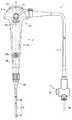
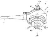
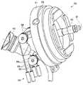
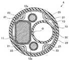
以下、図面を参照して本発明の形態を説明する。図面は本発明の一実施形態に係り、図1は内視鏡の外観を示す正面図、図2は内視鏡の外観を示す右側面図、図3は内視鏡の外観を示す上面図、図4はワイヤ牽引部材及びシリンダと信号ケーブル及びライトガイドとの配置関係を示す説明図、図5はワイヤ牽引機構とシリンダとの配置関係を示す斜視図、図6はワイヤ牽引機構の内部構造体を示す斜視図、図7はワイヤ牽引機構の内部構造体を示す分解斜視図、図8は操作部の要部断面図、図9は図8のIX矢視図、図10は操作部の左側部の内部構造を示す断面図、図11は操作部の右側部の内部構造を示す断面図、図12は先端部及び湾曲部の要部を示す横断面図、図13は図12のXIII−XIII断面図である。 Hereinafter, embodiments of the present invention will be described with reference to the drawings. 1 is a front view showing the appearance of the endoscope, FIG. 2 is a right side view showing the appearance of the endoscope, and FIG. 3 is a top view showing the appearance of the endoscope. 4 is an explanatory view showing the positional relationship between the wire pulling member and cylinder, the signal cable, and the light guide, FIG. 5 is a perspective view showing the positional relationship between the wire pulling mechanism and the cylinder, and FIG. 6 is an internal structure of the wire pulling mechanism. 7 is an exploded perspective view showing the internal structure of the wire pulling mechanism, FIG. 8 is a cross-sectional view of the main part of the operation unit, FIG. 9 is a view taken along the line IX in FIG. 8, and FIG. 11 is a cross-sectional view showing the internal structure of the left side portion, FIG. 11 is a cross-sectional view showing the internal structure of the right side portion of the operation unit, FIG. 12 is a cross-sectional view showing the main part of the tip portion and the bending portion, and FIG. It is -XIII sectional drawing.
図1,2に示すように、本実施形態の内視鏡1は気管支用の内視鏡であり、この内視鏡1は、細長管状に形成された挿入部2と、この挿入部2の基端に連設された操作部3と、この操作部3から延設された内視鏡ケーブルであるユニバーサルコード4と、このユニバーサルコード4の先端に配設された内視鏡コネクタ5と、を備えて構成されている。 As shown in FIGS. 1 and 2, the endoscope 1 of the present embodiment is a bronchial endoscope. The endoscope 1 includes an
挿入部2は、先端側から順に、先端部6、湾曲部7、可撓管部8が連設された可撓性を有する管状部材によって構成されている。 The
例えば、図12,13に示すように、先端部6内には金属製の先端硬質部10が設けられ、この先端硬質部10にはCCD,CMOS等の撮像素子を内蔵した撮像ユニット11、一対のライトガイド12a、及び、処置具挿通チャンネル13が保持されている。 For example, as shown in FIGS. 12 and 13, a metal tip
また、先端部6内において、先端硬質部10の基端側には、略円筒形状をなす最先端湾曲駒20が外嵌され、この最先端湾曲駒20の外周が湾曲ゴム22によって覆われている。最先端湾曲駒20の内周には、挿入軸O周りの4箇所にワイヤ固定部21が設けられ、各ワイヤ固定部21には、挿入部2内に挿通された4本のアングルワイヤ(牽引ワイヤ)23の何れかの先端がそれぞれ固定されている。 Further, in the
ここで、先端部6を太径化させることなく各構成部材を効率良く配置するため、先端硬質部10及び最先端湾曲駒20内には大型部材である撮像ユニット11と処置具挿通チャンネル13とが左右に並んで配置され、(図13参照)、これらの配置によって上下に形成されたスペースにライトガイド12aがそれぞれ配置されている。 Here, in order to efficiently arrange the constituent members without increasing the diameter of the
また、撮像ユニット11及び処置具挿通チャンネル13と、各アングルワイヤ23との干渉を回避するため、各ワイヤ固定部21は、先端部6の上下左右位置に対して挿入軸O周りに所定角度回転移動した位置に設けられている。すなわち、例えば、図13に示すように、最先端湾曲駒20には、先端部6の上方向を基準として挿入軸O周りに左右それぞれ15〜75度の範囲内で回転移動させた位置、及び、先端部6の下方向を基準として挿入軸O周りに左右それぞれ15〜75度の範囲内で回転移動させた位置に、各ワイヤ固定部21が設けられている。 Further, in order to avoid interference between the
湾曲部7は、操作部3に対する術者等の操作入力に応じて、上下左右方向(UP−DOWN/RIGHT−LEFT)を含む挿入軸O周りの全方向へと能動的に湾曲させ得るように構成されている。すなわち、本実施形態の湾曲部7は、複数の湾曲駒25が、挿入部2の上下方向に配置された枢軸部25aと、挿入部2の左右方向に配置された枢軸部25bと、を交互に介して連結された湾曲駒組24を有して構成されている。 The
この湾曲駒組24の内部には、撮像ユニット11から延在する信号ケーブル11a、ライトガイド12a、及び、処置具挿通チャンネル13が、先端部6内と略同様の配置にて挿通されている。また、湾曲駒組24を構成する所定の湾曲駒25には、挿入軸O周りの回転配置が上述の各ワイヤ固定部21と略同様となる位置に、各アングルワイヤ23をそれぞれ挿通するワイヤガイド(図示せず)が形成されている。さらに、湾曲駒組24の外周は、先端部6側から延在する湾曲ゴム22によって覆われている。 Inside the bending piece set 24, a
可撓管部8は、受動的に湾曲可能な可撓性を有する管状部材によって構成されている。この可撓管部8の内部には、上述の信号ケーブル11a、ライトガイド12a、及び、処置具挿通チャンネル13が挿通されている(ここでは、何れも不図示)。なお、図示しないが、これら一対のライトガイド12aの基端側は、可撓管部8内において1つのライトガイド12に束ねられている。 The
操作部3は、可撓管部8の基端を覆った状態にて当該可撓管部8に接続された折れ止部30と、この折れ止部30に連設され使用者等の手によって把持可能な把持部31と、この把持部31の基端側に連設された操作部本体32と、を有して構成されている。なお、本実施形態において、操作部3における挿入軸O周りの方向等は使用者等が把持部31を把持した状態を基準として定義されており、具体的には、操作部3には、把持部31を把持した使用者等を基準とする前後左右方向(前面、背面、及び、左右側面等)が定義されている。 The
図1に示すように、把持部31は、挿入軸O(中心軸)に対して左右対称な形状に形成され、使用者等が左手或いは右手の何れの手によっても同様に把持することが可能となっている。 As shown in FIG. 1, the
また、把持部31の先端側の前面には、処置具挿通部35が設けられている。この処置具挿通部35は、各種の処置具(不図示)を挿入する処置具挿通口35aを備えて構成されている。操作部3の内部において、処置具挿通口35aには、分岐部材36(図10,11参照)を介して、処置具挿通チャンネル13が連通されている。また、処置具挿通部35には、処置具挿通口35aを閉塞するための蓋部材である鉗子栓(不図示)が着脱自在となっている。 Further, a treatment
操作部本体32は、把持部31の基端側において、主として左右側方及び前方に膨出された略部分球状をなす中空部材によって構成されている。この操作部本体32の前面側には、内視鏡1の各種機能を実行するための操作ボタン群40が配設されている。一方、操作部本体32の背面側には、湾曲部7に対する湾曲操作を行うための操作レバーとしての湾曲レバー45が配設されている。さらに、操作部本体32の一側部(例えば、左側部)からは、ユニバーサルコード4が延出されている。 The operation portion
ユニバーサルコード4は、挿入部2の内部を通じて先端部6側から操作部3に至り、さらに操作部3から延出する信号ケーブル11a及びライトガイド12等を内部に挿通する複合ケーブルである。 The
内視鏡コネクタ5は、外部機器のビデオプロセッサ(不図示)との間を接続する信号ケーブルが接続される電気コネクタ部5aを有するとともに、外部機器である光源装置との間を接続するライトガイド及び電気ケーブルが接続される光源コネクタ部5bと、を有して構成されている。 The endoscope connector 5 has an
次に、操作部本体32における各部の構成について、より詳細に説明する。 Next, the structure of each part in the operation part
図1に示すように、操作ボタン群40は、例えば、操作部本体32に着脱自在に装着された吸引バルブ41から突出する吸引ボタン41aと、内視鏡1に関する各種機能の中から任意の機能を割り当てることが可能な2つのボタンスイッチ42と、を有して構成されている。 As shown in FIG. 1, the
これら吸引ボタン41a及びボタンスイッチ42は、操作部本体32の前面側において、左右対称となるよう配置されている。すなわち、本実施形態において、吸引ボタン41aは、挿入軸Oに重畳するよう、操作部本体32の左右幅方向の中央に配置されている。また、2つのボタンスイッチ42は、吸引ボタン41aよりも先端側において、挿入軸Oを挟んで左右対称な位置に配置されている。 The
ここで、例えば図4に示すように、操作部本体32の内部には、吸引バルブ41に連設するシリンダ43が設けられている。このシリンダ43は、吸引バルブ41を着脱自在に装着可能となっており、吸引ボタン41aの配置に対応して挿入軸Oに重畳するよう、操作部本体32の左右幅方向の中央に配置されている。 Here, for example, as shown in FIG. 4, a
湾曲レバー45は、例えば、上下左右方向を含む全方向に傾動可能なジョイスティック型のレバーによって構成されている。この湾曲レバー45は、操作部本体32の背面側において、左右対称となる位置に配置されている。すなわち、本実施形態において、湾曲レバー45は、挿入軸Oに重畳するよう、操作部本体32の左右幅方向の中央に配置されている。ここで、例えば、図3に示すように、この湾曲レバー45の傾動方向は、例えば、挿入軸Oに直交する方向である操作部3の左右幅方向に傾動操作の左右方向が定義され、この左右幅方向に直交する方向に上下方向が定義されている。 The bending
より具体的には、本実施形態の湾曲レバー45の傾動方向は、例えば、図3中の紙面左側が湾曲部7を左側に湾曲させるための傾動方向(左傾動方向)、図3中の紙面右側が湾曲部7を右側に湾曲させるための傾動方向(右傾動方向)、図3中の紙面下側が湾曲部7を上側に湾曲させるための傾動方向(上傾動方向)、図3中の紙面上側が湾曲部7を下側に湾曲させるための傾動方向(下傾動方向)としてそれぞれ定義されている。 More specifically, the tilting direction of the bending
湾曲レバー45の突端部には、使用者等の親指等を当接させることが可能な指当て部46が設けられている。また、図8に示すように、操作部3の内部において、湾曲レバー45の基端側にはワイヤ牽引機構50が連設され、さらに、このワイヤ牽引機構50には、中継レバー機構60を介して各アングルワイヤ23が接続されている。そして、湾曲レバー45は、これらワイヤ牽引機構50及び中継レバー機構60とともに、湾曲部7を任意の方向に湾曲動作させるための湾曲操作装置70を構成する。 The protruding end of the bending
図5〜8に示すように、ワイヤ牽引機構50は、ハウジング51と、このハウジング51内に回動(揺動)自在に軸支される回動枠52と、この回動枠52内に回動(揺動)自在に軸支されるベース部材53と、このベース部材53に固設されるワイヤ牽引部材54と、を有して構成されている。 As shown in FIGS. 5 to 8, the
ハウジング51は、略円筒形状をなす部材によって構成され、このハウジング51の周壁には、互いに対向する軸孔51aが穿設されている。 The
回動枠52は、例えば、略矩形形状をなす枠体によって構成されている。この回動枠52には、長手方向両端部の中央に互いに対向する一対のねじ孔52aが穿設され、さらに、短手方向両端部の中央に互いに対向する一対の軸孔52bが穿設されている。そして、ハウジング51の各軸孔51aにそれぞれ挿通されたビス55が各ねじ孔52aに螺合することにより、回動枠52はハウジング51に対して回動自在に軸支されている。 The rotating
ベース部材53は、略円柱形状をなす部材によって構成されている。このベース部材53の中心軸上には、湾曲レバー45が一体形成されている。また、ベース部材53の周部には、互いに対向する一対の平坦部53bが形成され、さらに、これら平坦部53bを貫通するねじ孔53cが穿設されている。このねじ孔53cには、回動枠52の各軸孔52bにそれぞれ挿通されたビス56が螺合され、これにより、ベース部材53は回動枠52に対して回動自在に軸支されている。そして、このようにベース部材53が回動枠52を介してハウジング51に支持されることにより、ベース部材53に対して一体に連設された湾曲レバー45は任意の方向に対して傾動することが可能となっている。 The
ワイヤ牽引部材54は、互いに異なる4方向にアーム部54bが延出された板状の部材によって構成されている。本実施形態において、より具体的には、ワイヤ牽引部材54は、互いに隣接するアーム部54bのなす角度が90度に設定された十字状の板状部材によって構成され、その中心部54aがビス57を介してベース部材53に固定されている。すなわち、ワイヤ牽引部材54にはベース部材53を介して湾曲レバー45が連結され、これにより、各アーム部54bの先端側は、湾曲レバー45の傾動動作に連動して変位可能となっている。また、このように変位可能に支持された各アーム部54bの先端側には、ワイヤ固定孔54cが穿設されている。なお、各アーム部54bのなす角度は90度に限定されるものではなく、例えば、当該90度を基準とする±30度の範囲内において任意に変更することも可能である。 The
このように構成されたワイヤ牽引機構50は、操作部本体32内において、シリンダ43と前後に対向するよう配置されている。この場合において、ワイヤ牽引機構50は、各アーム部54bが湾曲レバー45に定義された上下左右の傾動方向に対して当該湾曲レバー45の中心軸Ol周りにそれぞれ30度〜60度の範囲内で回転移動させた位置(例えば、45度回転移動させた位置)に配置されている。これにより、例えば、図4に示すように、ワイヤ牽引機構50は、ワイヤ牽引部材54の2つのアーム部54bの間にシリンダ43が臨まされた状態にて配置されている。 The
このシリンダ43には管路部としての吸引管路37の基端側が接続され、この吸引管路37の先端側は、分岐部材36を介して処置具挿通チャンネル13に連通されている。 The
図8,9に示すように、中継レバー機構60は、操作部本体32内から把持部31内へと延在する支持部材としての左右一対のステー61a,61bと、これらのステー61a,61bに支持された4本の中継レバー62と、を有して構成されている。 As shown in FIGS. 8 and 9, the
例えば、図7に示すように、ステー61a,61bの基端側は、連結部61cを介して一体的に連結されている。連結部61cには一対のねじ孔61dが穿設されており、これらのねじ孔61dに挿通されたビス64が、ハウジング51から突設されたブラケット51bに螺合されている。これにより、ステー61a,61bの基端は、ハウジング51を介して操作部本体32内に保持されている。そして、図7〜11に示すように、本実施形態において、このように操作部本体32内に保持された一対のステー61a,61bは、互いに対向しながら、長手軸O方向に沿って把持部31内に延在されている。 For example, as shown in FIG. 7, the base ends of the
ここで、図10に示すように、本実施形態において、これら一対のステー61a,61bのうちの一方のステー61aは、操作部3の剛性の確保等を目的として配設される所謂「地板」として機能するものである。このステー61aは、長手軸Oに沿って把持部31の先端まで延在され、その先端部に、分岐部材36をビス止め等によって支持するとともに、挿入部2の基端をリベット止め等によって支持する。換言すれば、本実施形態において、操作部3を補剛等するために設けられている地板が、ステー61aとして兼用されている。 Here, as shown in FIG. 10, in the present embodiment, one of the
また、これらのステー61a,61bの間には、上述の吸引管路37が配設されている。すなわち、吸引管路37は、基端側がシリンダ43を介して操作部3(操作部本体32)に固定されるとともに、先端側がステー61aに保持された分岐部材36を介して操作部3(把持部31)に固定されることにより、ステー61a,61bに沿って長手軸O方向に延在するように配設されている。そして、このようにステー61a,61b及び吸引管路37が並んで配設されることにより、操作部3の内部空間は、第1の空間部3aと第2の空間部3bとに区画されている。 Further, the above-described
このように区画された内部空間のうち、第2の空間部3bには、信号ケーブル11a及びライトガイド12を含む長尺内蔵物が配設されている。なお、第2の空間部3bに挿通された信号ケーブル11a及びライトガイド12等の長尺内蔵物の基端側は、例えば、図4に示すように、シリンダ43の側方を経由して、ユニバーサルコード4内に延出されている。 Among the internal spaces partitioned in this way, a long internal object including the
一方、第1の空間部3aには、中継レバー機構60を介してワイヤ牽引機構50に接続された各アングルワイヤ23が配設されている。 On the other hand, each
図8〜11に示すように、中継レバー機構60を構成する各中継レバー62は、把持部31内において左右一列に並んで配置されている。これら中継レバー62の固定端側は、左右のステー61a,61b間に架設する単一の軸部63によって軸支され、これにより、各中継レバー62の自由端側が第1の空間部3a内において揺動可能となっている。 As shown in FIGS. 8 to 11, the relay levers 62 constituting the
これら各中継レバー62はワイヤ牽引機構50の各アーム部54bに対応するものであり、各中継レバー62の中途には、湾曲レバー45の傾動動作に伴う各アーム部54bの変位量が中継ワイヤ65を介して伝達される力点62aが設定されている。さらに、力点62aよりも支点(軸部63)から離間した位置にある各中継レバー62の自由端側には、各アーム部54bの変位量を増幅して各アングルワイヤ23に伝達するための作用点62bが設定されている。 These relay levers 62 correspond to the
具体的に説明すると、例えば、図8,9に示すように、各アーム部54bのワイヤ固定孔54cには、中継ワイヤ65の基端側が接続されている。一方、各中継レバー62の力点62aには、中継ワイヤ65の長さを調整するためのネジ式の第1のワイヤ調整部66が設けられ、この第1のワイヤ調整部66を介して、中継ワイヤ65の先端側が接続されている。さらに、各中継ワイヤ65の中途には、操作部本体32に支持されたプーリ68が係合されている。 Specifically, for example, as shown in FIGS. 8 and 9, the proximal end side of the
そして、各中継ワイヤ65の基端側は、各プーリ68の配設位置の設定等により、湾曲レバー45が中立状態にあるときのアーム部54bの垂直方向に対して所定角度範囲内の角度(例えば、アーム部54bの垂直方向に対して±20°程度の誤差範囲内の角度)にて指向するよう調整されている。さらに、各中継ワイヤ65の先端側は、各プーリ68の配設位置の設定等により、湾曲レバー45が中立状態にあるときの中継レバー62の垂直方向に対して所定角度範囲内の角度(例えば、中継レバー62の垂直方向に対して±20°程度の誤差範囲内の角度)にて指向するよう調整されている。 Then, the base end side of each
また、例えば、図8,9に示すように、各中継レバー62の作用点62bには、アングルワイヤ23の長さを調整するためのネジ式の第2のワイヤ調整部67が設けられ、この第2のワイヤ調整部67を介して、アングルワイヤ23の基端側が接続されている。なお、各アングルワイヤ23の先端側は、上下左右がそれぞれクロスした状態にて挿入部2内に配索されている。 For example, as shown in FIGS. 8 and 9, a screw-type second
このような構成において、例えば、使用者等が操作部3の把持部31を把持し、把持した手の親指によって湾曲レバー45を左傾動方向に傾動させると、主として、右傾動方向に位置する2つのアーム部54bに連結された中継ワイヤ65が牽引される。これらの中継ワイヤ65への牽引は、対応する各中継レバー62に伝達され、各中継レバー62は牽引量に応じた角度にて揺動される。これにより、湾曲部7内においては、主として湾曲方向左側に位置する2本のアングルワイヤ23が中継レバー62によって増幅された牽引量にて牽引され、湾曲部7は左側に湾曲される。このとき、各アングルワイヤ23は操作部3内を進退移動することとなるが、これら各アングルワイヤ23は第1の空間部3a内に配設されており、信号ケーブル11a及びライトガイド12等の他の長尺内蔵物はステー61a,61b及び吸引管路37によって区画された第2の空間部3b内に配設されているため、各アングルワイヤ23と他の長尺内蔵物との干渉が的確に防止される。 In such a configuration, for example, when the user or the like grips the
また、例えば、使用者等が操作部3の把持部31を把持し、把持した手の親指によって湾曲レバー45を右傾動方向に傾動させると、主として、左傾動方向に位置する2つのアーム部54bに連結された中継ワイヤ65が牽引される。これらの中継ワイヤ65への牽引は、対応する各中継レバー62に伝達され、各中継レバー62は牽引量に応じた角度にて揺動される。これにより、湾曲部7内においては、主として湾曲方向右側に位置する2本のアングルワイヤ23が中継レバー62によって増幅された牽引量にて牽引され、湾曲部7は右側に湾曲される。このとき、各アングルワイヤ23は操作部3内を進退移動することとなるが、これら各アングルワイヤ23は第1の空間部3a内に配設されており、信号ケーブル11a及びライトガイド12等の他の長尺内蔵物はステー61a,61b及び吸引管路37によって区画された第2の空間部3b内に配設されているため、各アングルワイヤ23と他の長尺内蔵物との干渉が的確に防止される。 Further, for example, when the user or the like grips the
また、例えば、使用者等が操作部3の把持部31を把持し、把持した手の親指によって湾曲レバー45を上傾動方向に傾動させると、主として、下傾動方向に位置する2つのアーム部54bに連結された中継ワイヤ65が牽引される。これらの中継ワイヤ65への牽引は、対応する各中継レバー62に伝達され、各中継レバー62は牽引量に応じた角度にて揺動される。これにより、湾曲部7内においては、主として湾曲方向下側に位置する2本のアングルワイヤ23が中継レバー62によって増幅された牽引量にて牽引され、湾曲部7は上側に湾曲される。このとき、各アングルワイヤ23は操作部3内を進退移動することとなるが、これら各アングルワイヤ23は第1の空間部3a内に配設されており、信号ケーブル11a及びライトガイド12等の他の長尺内蔵物はステー61a,61b及び吸引管路37によって区画された第2の空間部3b内に配設されているため、各アングルワイヤ23と他の長尺内蔵物との干渉が的確に防止される。 Further, for example, when the user or the like grips the
また、例えば、使用者等が操作部3の把持部31を把持し、把持した手の親指によって湾曲レバー45を下傾動方向に傾動させると、主として、上傾動方向に位置する2つのアーム部54bに連結された中継ワイヤ65が牽引される。これらの中継ワイヤ65への牽引は、対応する各中継レバー62に伝達され、各中継レバー62は牽引量に応じた角度にて揺動される。これにより、湾曲部7内においては、主として湾曲方向上側に位置する2本のアングルワイヤ23が中継レバー62によって増幅された牽引量にて牽引され、湾曲部7は下側に湾曲される。このとき、各アングルワイヤ23は操作部3内を進退移動することとなるが、これら各アングルワイヤ23は第1の空間部3a内に配設されており、信号ケーブル11a及びライトガイド12等の他の長尺内蔵物はステー61a,61b及び吸引管路37によって区画された第2の空間部3b内に配設されているため、各アングルワイヤ23と他の長尺内蔵物との干渉が的確に防止される。 Further, for example, when the user or the like grips the
このような実施形態によれば、操作部3の内部において長手軸O方向に沿って延在するステー61a,61bと、操作部3の内部においてステー61a,61bに沿って長手軸O方向に延在するよう操作部3に先端側と基端側とが固定された吸引管路37と、を用いて操作部3の内部を第1の空間部3aと第2の空間部3bとに区画し、第1の空間部3a内に各アングルワイヤ23を配設するとともに、第2の空間部3b内に信号ケーブル11aやライトガイド12等の長尺内蔵物を配設することにより、アングルワイヤ23と他の内蔵物との干渉を防止しつつ、把持部31を効率良く小型化することができる。 According to such an embodiment, the
すなわち、支持部材として機能するステー61a,61bと、所定の管路部として機能する吸引管路37と、を並べて配置して操作部3の内部を第1の空間部3aと第2の空間部3bとに区画することにより、専用の仕切り等を用いることなく、各アングルワイヤ23と、信号ケーブル11a及びライトガイド12等の長尺内蔵物と、を異なる空間(第1,第2の空間部3a,3b)に配設することができる。そして、このように、各アングルワイヤ23と他の長尺内蔵物とをそれぞれ異なる第1,第2の空間部3a,3b内に配設することにより、これらの干渉回避を目的として操作部3の内部空間を必要以上に大きく確保する必要がなく、把持部31を効率良く小型化(細径化等)することができる。 That is, stays 61a and 61b that function as support members and a
この場合において、ワイヤ牽引機構50と各アングルワイヤ23との間に中継レバー62を介在させることにより、各アングルワイヤ23を第1の空間部3a内に配置する際に、各アングルワイヤ23の延在方向を容易に調整することができる。 In this case, by interposing the
特に、各中継レバー62を単一の軸部63上に並べて軸支することにより、中継レバー62を一箇所に集約して配置することができ、各アングルワイヤ23を第1の空間部3a内に効率良く整列させた状態にて配置することができる。 In particular, by arranging the relay levers 62 on the
また、各中継レバー62を支持するステー61aは、所謂地板を兼用するものであるため、中継レバー62を設けた場合にも、必要以上の部品点数の増加を抑制することができ、把持部31を効率良く小型化することができる。 In addition, since the
なお、本発明は、以上説明した各実施形態に限定されることなく、種々の変形や変更が可能であり、それらも本発明の技術的範囲内である。 In addition, this invention is not limited to each embodiment described above, A various deformation | transformation and change are possible, and they are also in the technical scope of this invention.
例えば、長尺内蔵物は、上述の信号ケーブル11aやライトガイド12等に限定されるものではなく、内視鏡の種類等に応じて、他の各種内蔵物を対象とすることも可能である。 For example, the long built-in object is not limited to the
また、上述の実施形態においては、操作部3の内部に支持部材として一対のステー61a,61bを設けた構成の一例について説明したが、本発明はこれに限定されるものではなく、例えば、ステー61bを適宜省略することも可能である。逆に、操作部3の更なる剛性の向上等を目的として、一対のステー61a,61bをともに把持部31の先端まで延在させ、所謂地板としての機能を兼用させてもよい。 In the above-described embodiment, an example of a configuration in which the pair of
本出願は、2015年6月29日に日本国に出願された特願2015−130127号を優先権主張の基礎として出願するものであり、上記の開示内容は、本願明細書、請求の範囲に引用されるものとする。 This application is filed on the basis of priority claim of Japanese Patent Application No. 2015-130127 filed in Japan on June 29, 2015. The above disclosure is included in the present specification and claims. Shall be quoted.
Claims (4)
Translated fromJapanese前記挿入部の基端側に配設された操作部と、
前記操作部の内部において長手軸方向に沿って延在する支持部材と、
前記操作部の内部において前記支持部材に沿って長手軸方向に延在するよう、前記操作部に先端側と基端側とが固定され、前記操作部の内部空間を前記支持部材とともに第1の空間部と第2の空間部とに区画する管路部と、
前記操作部の内部において前記第1の空間部に配設され、前記湾曲部を湾曲させるアングルワイヤと、
前記操作部の内部において前記第2の空間部に配設され、前記挿入部から延出された長尺内蔵物と、を備えたことを特徴とする内視鏡。An insertion part that can be inserted into a subject and has a bending part that can be bent in at least two directions centered on a longitudinal axis direction;
An operation portion disposed on a proximal end side of the insertion portion;
A support member extending along the longitudinal axis in the operation portion;
A distal end side and a proximal end side are fixed to the operation portion so as to extend in the longitudinal axis direction along the support member inside the operation portion, and the internal space of the operation portion is combined with the support member into the first space. A pipeline section that divides into a space section and a second space section;
An angle wire that is disposed in the first space portion inside the operation portion and bends the bending portion;
An endoscope comprising: a long built-in object disposed in the second space portion inside the operation portion and extending from the insertion portion.
Applications Claiming Priority (3)
| Application Number | Priority Date | Filing Date | Title |
|---|---|---|---|
| JP2015130127 | 2015-06-29 | ||
| JP2015130127 | 2015-06-29 | ||
| PCT/JP2016/061146WO2017002424A1 (en) | 2015-06-29 | 2016-04-05 | Endoscope |
Publications (2)
| Publication Number | Publication Date |
|---|---|
| JP6081684B1true JP6081684B1 (en) | 2017-02-15 |
| JPWO2017002424A1 JPWO2017002424A1 (en) | 2017-07-06 |
Family
ID=57608197
Family Applications (1)
| Application Number | Title | Priority Date | Filing Date |
|---|---|---|---|
| JP2016567945AActiveJP6081684B1 (en) | 2015-06-29 | 2016-04-05 | Endoscope |
Country Status (5)
| Country | Link |
|---|---|
| US (1) | US10219682B2 (en) |
| EP (1) | EP3207854A4 (en) |
| JP (1) | JP6081684B1 (en) |
| CN (1) | CN107072502A (en) |
| WO (1) | WO2017002424A1 (en) |
Families Citing this family (10)
| Publication number | Priority date | Publication date | Assignee | Title |
|---|---|---|---|---|
| JP6219008B1 (en)* | 2016-04-25 | 2017-10-25 | オリンパス株式会社 | Endoscope |
| CN109068949A (en)* | 2016-04-25 | 2018-12-21 | 奥林巴斯株式会社 | Endoscope |
| CN109890262B (en)* | 2016-12-26 | 2021-10-08 | 奥林巴斯株式会社 | Endoscope with a detachable handle |
| JP3215550U (en)* | 2017-01-25 | 2018-03-29 | 珠海嘉潤医用影像科技有限公司Zhuhai Kaden Medical Imaging Technology Co., Ltd | Control mechanism for tension cord of bronchoscope |
| WO2018162556A1 (en) | 2017-03-08 | 2018-09-13 | Ambu A/S | A handle for an endoscope |
| EP3906837B1 (en) | 2017-03-08 | 2023-08-09 | Ambu A/S | Handle for an endoscope |
| WO2018162559A1 (en) | 2017-03-08 | 2018-09-13 | Ambu A/S | A handle for an endoscope |
| WO2020188723A1 (en)* | 2019-03-18 | 2020-09-24 | オリンパス株式会社 | Holding frame, endoscope distal end structure, and endoscope |
| CN113966190B (en)* | 2019-05-01 | 2025-08-29 | 波士顿科学国际有限公司 | Cavity handle of medical device |
| WO2021071715A1 (en)* | 2019-10-07 | 2021-04-15 | Boston Scientific Scimed, Inc. | Endoscopic device with interchangeable shaft |
Citations (4)
| Publication number | Priority date | Publication date | Assignee | Title |
|---|---|---|---|---|
| JPH08224211A (en)* | 1995-02-21 | 1996-09-03 | Asahi Optical Co Ltd | Endoscope |
| JPH0984739A (en)* | 1995-09-22 | 1997-03-31 | Fuji Photo Optical Co Ltd | Airtight structure of endoscope hand operating part |
| JP2000051148A (en)* | 1998-08-10 | 2000-02-22 | Olympus Optical Co Ltd | Removal of loosening of operation wire of endoscope |
| JP2012135515A (en)* | 2010-12-27 | 2012-07-19 | Hoya Corp | Endoscope device |
Family Cites Families (37)
| Publication number | Priority date | Publication date | Assignee | Title |
|---|---|---|---|---|
| EP0100977B1 (en)* | 1982-08-09 | 1988-01-20 | Olympus Optical Co., Ltd. | Endoscope |
| US4534339A (en)* | 1983-10-17 | 1985-08-13 | Warner-Lambert Technologies, Inc. | Endoscope |
| US4742817A (en)* | 1985-05-15 | 1988-05-10 | Olympus Optical Co., Ltd. | Endoscopic apparatus having a bendable insertion section |
| JPH01104237A (en)* | 1987-03-27 | 1989-04-21 | Olympus Optical Co Ltd | Apparatus for bending operation of endoscope |
| US4905666A (en)* | 1987-03-27 | 1990-03-06 | Olympus Optical Co., Ltd. | Bending device for an endoscope |
| US5097838A (en)* | 1989-04-27 | 1992-03-24 | Olympus Optical Co., Ltd. | Ultrasonic endoscope |
| EP0415553B1 (en)* | 1989-07-31 | 1996-01-17 | Kabushiki Kaisha Machida Seisakusho | Bending device |
| DE3933856A1 (en)* | 1989-10-07 | 1991-04-18 | Wiest Peter P | DEVICE FOR RINSING AND SUCTIONING BODY CAVES |
| JPH03264041A (en)* | 1990-03-14 | 1991-11-25 | Machida Endscope Co Ltd | Curving operating device |
| JPH04322633A (en)* | 1991-04-19 | 1992-11-12 | Olympus Optical Co Ltd | Endoscope |
| US5312327A (en)* | 1992-10-09 | 1994-05-17 | Symbiosis Corporation | Cautery override safety systems endoscopic electrosurgical suction-irrigation instrument |
| US5472017A (en)* | 1992-11-17 | 1995-12-05 | Life Medical Technologies, Inc. | Deflectable catheter |
| US5415158A (en)* | 1993-06-11 | 1995-05-16 | Clarus Medical Systems, Inc. | Flexible endoscope with force limiting spring coupler |
| JP3509207B2 (en)* | 1994-07-22 | 2004-03-22 | 富士写真光機株式会社 | Assembly part in the endoscope |
| US5667476A (en)* | 1995-06-05 | 1997-09-16 | Vision-Sciences, Inc. | Endoscope articulation system to reduce effort during articulation of an endoscope |
| JP3500527B2 (en)* | 1995-12-13 | 2004-02-23 | 富士写真光機株式会社 | Endoscope operation unit |
| JPH10216078A (en)* | 1997-02-06 | 1998-08-18 | Olympus Optical Co Ltd | Endoscope |
| JP4076252B2 (en)* | 1998-01-06 | 2008-04-16 | オリンパス株式会社 | Endoscope |
| US6491627B1 (en)* | 1999-08-18 | 2002-12-10 | Fuji Photo Optical Co., Ltd. | Manipulation mechanism for an angle section of an endoscope |
| JP4323149B2 (en)* | 2002-09-30 | 2009-09-02 | オリンパス株式会社 | Electric bending endoscope |
| ES2552252T3 (en)* | 2004-03-23 | 2015-11-26 | Boston Scientific Limited | Live View System |
| WO2006073186A1 (en)* | 2005-01-07 | 2006-07-13 | Olympus Medical Systems Corp. | Endoscope-use insertion unit |
| JP4794934B2 (en)* | 2005-07-22 | 2011-10-19 | オリンパスメディカルシステムズ株式会社 | Endoscope |
| JP4789597B2 (en)* | 2005-11-22 | 2011-10-12 | オリンパスメディカルシステムズ株式会社 | Endoscope |
| US7785333B2 (en)* | 2006-02-21 | 2010-08-31 | Olympus Medical Systems Corp. | Overtube and operative procedure via bodily orifice |
| US20080262293A1 (en)* | 2007-04-19 | 2008-10-23 | Olympus Medical Systems Corp | Endoscopic operation assisting device |
| JP5139742B2 (en)* | 2007-08-03 | 2013-02-06 | オリンパスメディカルシステムズ株式会社 | Endoscope |
| US8777839B2 (en)* | 2008-09-02 | 2014-07-15 | Olympus Medical Systems Corp. | Shock absorbing mechanism and medical instrument |
| CN102858223B (en)* | 2010-04-28 | 2015-04-29 | 奥林巴斯医疗株式会社 | Operating Mechanism, Endoscopic Device and Guiding Catheter |
| WO2013019859A1 (en)* | 2011-08-03 | 2013-02-07 | Alcon Research, Ltd. | Articulating ophthalmic surgical probe |
| JP2013150700A (en)* | 2012-01-25 | 2013-08-08 | Fujifilm Corp | Endoscope |
| EP2783621B1 (en)* | 2012-07-02 | 2017-10-04 | Olympus Corporation | Insertion instrument |
| EP2759250B1 (en) | 2012-09-05 | 2017-09-27 | Olympus Corporation | Endoscope |
| CN104349708B (en)* | 2013-01-11 | 2016-10-05 | 奥林巴斯株式会社 | Endoscope bending angle adjustment mechanism and endoscope having the bending angle adjustment mechanism |
| JP5657843B1 (en)* | 2013-02-07 | 2015-01-21 | オリンパスメディカルシステムズ株式会社 | Endoscope operation unit structure |
| US9968241B2 (en)* | 2013-02-22 | 2018-05-15 | Ambu A/S | Apparatus for maintaining a tensioned pull-wire in an endoscope |
| CN106455918B (en)* | 2014-09-16 | 2018-11-20 | 奥林巴斯株式会社 | endoscope |
- 2016
- 2016-04-05WOPCT/JP2016/061146patent/WO2017002424A1/ennot_activeCeased
- 2016-04-05CNCN201680003668.9Apatent/CN107072502A/enactivePending
- 2016-04-05JPJP2016567945Apatent/JP6081684B1/enactiveActive
- 2016-04-05EPEP16817534.7Apatent/EP3207854A4/ennot_activeWithdrawn
- 2017
- 2017-05-17USUS15/597,560patent/US10219682B2/enactiveActive
Patent Citations (4)
| Publication number | Priority date | Publication date | Assignee | Title |
|---|---|---|---|---|
| JPH08224211A (en)* | 1995-02-21 | 1996-09-03 | Asahi Optical Co Ltd | Endoscope |
| JPH0984739A (en)* | 1995-09-22 | 1997-03-31 | Fuji Photo Optical Co Ltd | Airtight structure of endoscope hand operating part |
| JP2000051148A (en)* | 1998-08-10 | 2000-02-22 | Olympus Optical Co Ltd | Removal of loosening of operation wire of endoscope |
| JP2012135515A (en)* | 2010-12-27 | 2012-07-19 | Hoya Corp | Endoscope device |
Also Published As
| Publication number | Publication date |
|---|---|
| US10219682B2 (en) | 2019-03-05 |
| WO2017002424A1 (en) | 2017-01-05 |
| US20170251906A1 (en) | 2017-09-07 |
| CN107072502A (en) | 2017-08-18 |
| JPWO2017002424A1 (en) | 2017-07-06 |
| EP3207854A1 (en) | 2017-08-23 |
| EP3207854A4 (en) | 2018-08-08 |
Similar Documents
| Publication | Publication Date | Title |
|---|---|---|
| JP6081684B1 (en) | Endoscope | |
| JP5930255B2 (en) | Endoscope | |
| JP6076556B1 (en) | Bending operation device and endoscope | |
| JP6116777B1 (en) | Bending operation device and endoscope | |
| JP6301014B2 (en) | Bending operation device and endoscope | |
| JP6091733B1 (en) | Endoscope | |
| CN110730629B (en) | Endoscope operation unit | |
| WO2017002423A1 (en) | Endoscope | |
| WO2016199476A1 (en) | Endoscope | |
| US11064872B2 (en) | Bending operation device and endoscope with the same applied thereto | |
| WO2021070389A1 (en) | Bending operation mechanism for endoscope | |
| JPWO2015174128A1 (en) | Endoscope | |
| JPWO2017145431A1 (en) | Endoscope |
Legal Events
| Date | Code | Title | Description |
|---|---|---|---|
| A621 | Written request for application examination | Free format text:JAPANESE INTERMEDIATE CODE: A621 Effective date:20161115 | |
| A871 | Explanation of circumstances concerning accelerated examination | Free format text:JAPANESE INTERMEDIATE CODE: A871 Effective date:20161115 | |
| TRDD | Decision of grant or rejection written | ||
| A975 | Report on accelerated examination | Free format text:JAPANESE INTERMEDIATE CODE: A971005 Effective date:20161221 | |
| A01 | Written decision to grant a patent or to grant a registration (utility model) | Free format text:JAPANESE INTERMEDIATE CODE: A01 Effective date:20161227 | |
| A61 | First payment of annual fees (during grant procedure) | Free format text:JAPANESE INTERMEDIATE CODE: A61 Effective date:20170118 | |
| R151 | Written notification of patent or utility model registration | Ref document number:6081684 Country of ref document:JP Free format text:JAPANESE INTERMEDIATE CODE: R151 | |
| R250 | Receipt of annual fees | Free format text:JAPANESE INTERMEDIATE CODE: R250 | |
| R250 | Receipt of annual fees | Free format text:JAPANESE INTERMEDIATE CODE: R250 | |
| R250 | Receipt of annual fees | Free format text:JAPANESE INTERMEDIATE CODE: R250 | |
| R250 | Receipt of annual fees | Free format text:JAPANESE INTERMEDIATE CODE: R250 | |
| R250 | Receipt of annual fees | Free format text:JAPANESE INTERMEDIATE CODE: R250 | |
| R250 | Receipt of annual fees | Free format text:JAPANESE INTERMEDIATE CODE: R250 |