JP6080086B2 - Pointing stick - Google Patents
Pointing stickDownload PDFInfo
- Publication number
- JP6080086B2 JP6080086B2JP2013057456AJP2013057456AJP6080086B2JP 6080086 B2JP6080086 B2JP 6080086B2JP 2013057456 AJP2013057456 AJP 2013057456AJP 2013057456 AJP2013057456 AJP 2013057456AJP 6080086 B2JP6080086 B2JP 6080086B2
- Authority
- JP
- Japan
- Prior art keywords
- fixing plate
- pointing stick
- annular support
- lower fixing
- fastening member
- Prior art date
- Legal status (The legal status is an assumption and is not a legal conclusion. Google has not performed a legal analysis and makes no representation as to the accuracy of the status listed.)
- Expired - Fee Related
Links
- 238000005452bendingMethods0.000claimsdescription34
- 238000003780insertionMethods0.000claimsdescription21
- 230000037431insertionEffects0.000claimsdescription21
- 238000001514detection methodMethods0.000description31
- 239000010408filmSubstances0.000description16
- 239000000758substrateSubstances0.000description16
- 239000000853adhesiveSubstances0.000description12
- 230000001070adhesive effectEffects0.000description11
- 230000008859changeEffects0.000description6
- 238000005520cutting processMethods0.000description6
- 238000003466weldingMethods0.000description5
- 238000004519manufacturing processMethods0.000description4
- 230000004048modificationEffects0.000description4
- 238000012986modificationMethods0.000description4
- 238000003825pressingMethods0.000description4
- 239000000463materialSubstances0.000description3
- 239000013039cover filmSubstances0.000description2
- 238000006073displacement reactionMethods0.000description2
- 230000000694effectsEffects0.000description2
- 239000007788liquidSubstances0.000description2
- 230000000630rising effectEffects0.000description2
- 230000035945sensitivityEffects0.000description2
- XLYOFNOQVPJJNP-UHFFFAOYSA-NwaterSubstancesOXLYOFNOQVPJJNP-UHFFFAOYSA-N0.000description2
- 230000008901benefitEffects0.000description1
- 239000012141concentrateSubstances0.000description1
- 238000010586diagramMethods0.000description1
- 239000000428dustSubstances0.000description1
- 239000002184metalSubstances0.000description1
- 238000000034methodMethods0.000description1
- 230000008569processEffects0.000description1
- 230000009467reductionEffects0.000description1
- 239000011347resinSubstances0.000description1
- 229920005989resinPolymers0.000description1
Images


Landscapes
- Position Input By Displaying (AREA)
- Measurement Of Force In General (AREA)
- Transmission And Conversion Of Sensor Element Output (AREA)
Description
Translated fromJapanese本発明は、入力操作に用いるポインティングスティックに関し、特に、薄型化しても安定した出力が得られるポインティングスティックに関する。 The present invention relates to a pointing stick used for an input operation, and more particularly to a pointing stick that can obtain a stable output even if it is thinned.
ノート型コンピュータ等の携帯型電子機器において、傾倒させる力を加えて操作するポインティングスティックが入力操作に用いられている。ポインティングスティックは微小な変位を検出するものであって、正確な検出が非常に難しいものであり、検出特性の向上の努力が続けられている。また、携帯型電子機器の薄型化が進んでポインティングスティックも極限的な薄型化が求められている。 In a portable electronic device such as a notebook computer, a pointing stick that is operated by applying a tilting force is used for an input operation. Pointing sticks detect minute displacements, and are extremely difficult to detect accurately. Efforts are being made to improve detection characteristics. In addition, as portable electronic devices are becoming thinner, pointing sticks are also required to be extremely thin.
特許文献1には、操作体(操作部)を上下の固定部材で固定するポインティングスティックの構造が開示されている。
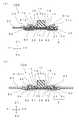
図11は、従来のポインティングスティック200を示す断面図である。ポインティングスティック200には、上下の固定部材である第1の支持材210と第2の支持材220との間にベースプレート500を挟んだ状態でこれを第1の支持材210と第2の支持材220とで挟持する挟持部に加えて、第1の支持材210には操作部201を外部に突出させるための開口部210aが備わっている。また、開口部210a近傍には第1の支持材210の立ち上がり部211が備わり、この立ち上がり部211と第2の支持材220との間に隙間を形成し、この隙間を利用して第1の支持材210と第2の支持材220とで操作部201を挟み込む操作部取付用挟持部233が備わっている。 FIG. 11 is a cross-sectional view showing a
このような構成を有することで、操作部201を第2の支持材220へ溶着する作業を無くすことが可能になる。ベースプレート500へのポインティングスティック取り付け作業において、第1の支持材210と第2の支持材220を溶接又はかしめ構造で一体化すると同時に、ベースプレート500と操作部201を両支持材210、220で挟み込むことができる。これにより、作業工程の簡略化、ひいては製造コストの低減を達成できる。また、操作部201がベースプレート500に直接溶着されない構造とされているので、ベースプレート500の歪みが操作部201に配置された検出素子に伝わりにくくなっている。 By having such a configuration, it is possible to eliminate the operation of welding the
このように、従来のポインティングスティック200では、第1の支持材210と第2の支持材220を溶接又はかしめ構造で一体化することによって、操作部201を両支持材210、220で挟み込む押圧力を発生させていた。 As described above, in the
しかしながら、第1の支持材210と第2の支持材220は溶接又はかしめ構造で一体化されるので、操作部201を第1の支持材210と第2の支持材220とで挟持する押圧力がばらついてしまう。そのため、不均一な押圧力が加わることによって操作部201に歪みを生じ、その歪みが操作部201に配置された検出素子に伝達されてしまう。このために、操作部201の操作を検出する検出特性の安定性が悪化する、という問題があった。 However, since the
それを防止するためには、剛性の高い厚肉の支持材(固定板)を用い、さらに、操作部(操作体)201の被挟持部(固定部)を厚肉に形成すればよい。こうすれば、溶接等で一体化するときの支持材の歪みを生じにくくできるとともに、被挟持部を厚肉に形成しているので変形しにくくなり、歪みを抑制できる。しかしながら、第1の支持材210と第2の支持材220とで挟持される操作部取付用挟持部233の厚みが増して薄型化が困難になる、という問題があった。 In order to prevent this, it is only necessary to use a thick support material (fixed plate) with high rigidity and to form a sandwiched portion (fixed portion) of the operation portion (operation body) 201 thick. If it carries out like this, while it becomes difficult to produce the distortion of a support material when integrating by welding etc., since the to-be-clamped part is formed thickly, it becomes difficult to deform | transform and can suppress distortion. However, there has been a problem that it is difficult to reduce the thickness because the thickness of the operation portion mounting sandwiching portion 233 sandwiched between the
本発明は、上述した課題を解決して、検出特性の安定性が高く、薄型化を図ることができるポインティングスティックを提供することを目的とする。 SUMMARY OF THE INVENTION An object of the present invention is to provide a pointing stick that solves the above-described problems and has high detection characteristics and can be thinned.
本発明は、複数の撓み部が形成された基部と、前記基部から上方に突出する操作部と、前記基部を取り囲むように延設された環状支持部と、を有する操作体と、前記複数の撓み部のそれぞれの撓み量を検出する複数のセンサ素子と、前記環状支持部を挟んで固定する上側固定板及び下側固定板と、を備えたポインティングスティックにおいて、前記環状支持部は、前記下側固定板に支持される本体部と、前記下側固定板に沿って前記本体部の外周から外方に延設されるとともに前記本体部の上下方向の厚みより薄く形成された固定部とを有し、前記固定部において前記上側固定板及び前記下側固定板に挟持され、前記下側固定板は平面視で前記環状支持部より外側に広がって形成されて、前記上側固定板は平面視で前記環状支持部より外側に広がって形成されていることを特徴とする。The present invention includes an operating body having a base portion on which a plurality of bending portions are formed, an operating portion protruding upward from the base portion, and an annular support portion extending so as to surround the base portion, A pointing stick comprising a plurality of sensor elements that detect the amount of bending of each of the bending portions, and an upper fixing plate and a lower fixing plate that are fixed with the annular supporting portion interposed therebetween, wherein the annular supporting portion is the lower supporting plate. A main body portion supported by a side fixing plate, and a fixing portion that extends outward from the outer periphery of the main body portion along the lower fixing plate and is thinner than the vertical thickness of the main body portion. The fixing portion is sandwiched between the upper fixing plate and the lower fixing plate, and the lowerfixing plate is formed to extend outward from the annular support portion in plan view, and the upper fixing plate is viewed in plan view. On the outside of the annular support Characterized in that itis formed wants.
環状支持部は、下側固定板に沿って本体部の外周から外方に延設された固定部において上側固定板及び下側固定板に挟持されるので、剛性の高い固定部材を使用しても、固定部と基部の間に環状支持部の本体部が介在するため、固定部には歪みが生じるものの、撓み部には歪みが伝達されない。そのため、検出特性の安定性を向上させることができる。また、環状支持部の本体部は、上側固定板及び下側固定板に固定される固定部から離れていることにより歪みを生じないので、厚肉に形成する必要がない。そのため、環状支持部の薄型化を図ることができる。下側固定板の外側エッジには切断時に発生したバリが残ることがある。また、上側固定板の外側エッジには切断時に発生したバリが残ることがある。操作体がそのバリの上に固定されていると、操作体を操作したときそのバリの影響により検出特性が悪化する。しかし、この構成によれば、操作体は常に外側エッジの内側に位置するので、バリによる検出特性の悪化を生じさせないようにすることができる。Since the annular support portion is sandwiched between the upper fixing plate and the lower fixing plate at the fixing portion extending outward from the outer periphery of the main body portion along the lower fixing plate, a highly rigid fixing member is used. However, since the main body portion of the annular support portion is interposed between the fixing portion and the base portion, although distortion occurs in the fixing portion, strain is not transmitted to the bending portion. Therefore, the stability of detection characteristics can be improved. Further, since the main body portion of the annular support portion is not distorted by being separated from the fixing portions fixed to the upper fixing plate and the lower fixing plate, it is not necessary to form a thick wall. Therefore, it is possible to reduce the thickness of the annular support portion.Burr generated during cutting may remain on the outer edge of the lower fixing plate. In addition, burrs generated during cutting may remain on the outer edge of the upper fixing plate. If the operating body is fixed on the burr, the detection characteristics deteriorate due to the influence of the burr when the operating body is operated. However, according to this configuration, since the operating body is always located inside the outer edge, it is possible to prevent the detection characteristics from being deteriorated by the burr.
また本発明のポインティングスティックにおいて、前記上側固定板及び前記下側固定板を締結する締結部材を有し、前記固定部は、前記本体部の外周から外方に向かって突出する複数の突出片を有し、前記複数の突出片に締結部材挿通孔が形成されており、前記締結部材挿通孔に前記締結部材を挿通して、前記上側固定板と前記下側固定板との間に前記複数の突出片が締結されていることを特徴とする。 In the pointing stick of the present invention, the pointing stick has a fastening member for fastening the upper fixing plate and the lower fixing plate, and the fixing portion includes a plurality of protruding pieces protruding outward from the outer periphery of the main body portion. A fastening member insertion hole is formed in the plurality of projecting pieces, the fastening member is inserted into the fastening member insertion hole, and the plurality of the plurality of protruding pieces are interposed between the upper fixing plate and the lower fixing plate. The protruding piece is fastened.
一般的に、締結部材による固定はその近傍で大きな歪みを生じやすい。本構成によれば、固定部は本体部の外周から外方に向かって突出する複数の突出片であり、突出片に形成された締結部材挿通孔の位置で締結部材によって固定されるので、締結部材による歪みが撓み部に伝わりにくく、検出特性の安定性をより向上させることができる。 In general, fixing with a fastening member tends to cause a large distortion in the vicinity thereof. According to this configuration, the fixing portion is a plurality of protruding pieces protruding outward from the outer periphery of the main body, and is fastened by the fastening member at the position of the fastening member insertion hole formed in the protruding piece. The distortion due to the member is difficult to be transmitted to the bent portion, and the stability of the detection characteristics can be further improved.
本発明のポインティングスティックにおいて、前記複数の撓み部は、平面視で前記操作部を中心としてそれぞれ前後左右の4方向に延設され、前記締結部材挿通孔は、前記操作部を中心として前記複数の撓み部の隣り合う同士の間の4方向に位置することを特徴とする。 In the pointing stick according to the aspect of the invention, the plurality of flexures may extend in four directions, front, rear, left, and right, with the operation unit as a center in a plan view, and the fastening member insertion hole may have the plurality of the center with the operation unit as a center. It is characterized by being positioned in four directions between adjacent ones of the flexures.
この構成によれば、締結部材挿通孔を平面視で4方向の撓み部の間の4方向に配置し、撓み部から離れた位置で締結部材により締結したので、締結部材による歪みが撓み部に伝わりにくく、検出特性の安定性をより一層向上させることができる。また、締結部材挿通孔を撓み部に近づけることなく、水平方向における小型化を図ることができる。 According to this configuration, the fastening member insertion holes are arranged in the four directions between the four bending portions in a plan view and fastened by the fastening member at a position away from the bending portion, so that the distortion due to the fastening member is caused in the bending portion. It is difficult to transmit and the stability of detection characteristics can be further improved. Further, it is possible to reduce the size in the horizontal direction without bringing the fastening member insertion hole close to the bending portion.
本発明のポインティングスティックにおいて、前記上側固定板は前記本体部を内側に挿入可能な円形開口部を備え、前記環状支持部は、前記円形開口部の縁部と前記下側固定板とで前記固定部において挟持されていることを特徴とする。 In the pointing stick of the present invention, the upper fixing plate includes a circular opening portion into which the main body portion can be inserted, and the annular support portion is fixed by the edge portion of the circular opening portion and the lower fixing plate. It is characterized by being clamped at the part.
この構成によれば、円形開口部の縁部が、ほぼ全周に亘って固定部における操作部から距離が等しい地点を均一な力で挟持することになるので、本体部の外周に不均一な歪みが発生せず、検出特性の安定性をより向上させることができる。 According to this configuration, the edge of the circular opening is sandwiched with a uniform force at a point where the distance from the operation part in the fixed part is the same over the entire circumference. Distortion does not occur and the stability of detection characteristics can be further improved.
本発明のポインティングスティックにおいて、前記本体部の外周は前記円形開口部と略等しい円形に形成されるとともに外側方向に突出する突出部を有し、前記円形開口部の縁部には前記突出部が挿入される切欠部が形成されていることを特徴とする。 In the pointing stick of the present invention, an outer periphery of the main body is formed in a circle substantially equal to the circular opening and has a protruding portion protruding outward, and the protruding portion is formed at an edge of the circular opening. A notch to be inserted is formed.
この構成によれば、円形開口部の縁部に形成された切欠部に、本体部の外周に形成された突出部が挿入されるので、操作体を組み立てる際の部材の位置決めおよび回転止めをすることができる。 According to this configuration, since the protrusion formed on the outer periphery of the main body is inserted into the notch formed at the edge of the circular opening, the member is positioned and stopped when the operation body is assembled. be able to.
本発明によれば、環状支持部は、下側固定板に沿って本体部の外周から外方に延設された固定部において上側固定板及び下側固定板に挟持されるので、撓み部には歪みが伝達されない。そのため、検出特性の安定性を向上させることができる。また、環状支持部の本体部は、上側固定板及び下側固定板に固定される固定部から離れていることにより歪みを生じないので、環状支持部の薄型化を図ることができる。さらに、操作体は常に外側エッジの内側に位置するので、バリによる検出特性の悪化を生じさせないようにすることができる。したがって、検出特性の安定性が高く、薄型化を図ることができるポインティングスティックを提供することができる。
According to the present invention, the annular support portion is sandwiched between the upper fixing plate and the lower fixing plate in the fixing portion extending outward from the outer periphery of the main body portion along the lower fixing plate. No distortion is transmitted. Therefore, the stability of detection characteristics can be improved. In addition, since the main body portion of the annular support portion is not distorted by being separated from the fixing portions fixed to the upper fixing plate and the lower fixing plate, the annular supporting portion can be thinned.Furthermore, since the operating body is always located inside the outer edge, it is possible to prevent the detection characteristics from being deteriorated by burrs. Therefore, it is possible to provide a pointing stick that has high detection characteristics and can be thinned.
[第1実施形態]
以下に第1実施形態におけるポインティングスティック100について説明する。[First Embodiment]
Hereinafter, the
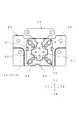
図1は、本発明の第1実施形態のポインティングスティック100を示す斜視図である。図2は、第1実施形態のポインティングスティック100を示す平面図である。図3は第1実施形態のポインティングスティック100を示す分解斜視図である。図4は、図3の反対方向から見た分解斜視図である。図5は、図3及び図4に示す操作体10の説明図である。図6は、図5に示す操作体10の底面図である。図7は、第1実施形態のポインティングスティック100を示す断面図であり、図7(a)は図2のA−A線で切断した断面図であり、図7(b)は図2のB−B線で切断した断面図である。図8は、図2のC−C線で切断した断面図である。図9は、操作体10とフィルム基板20との配置を示す底面図である。なお、説明を分かりやすくするため、ここでは、図1に示すZ1側を上方、Z2側を下方とする。 FIG. 1 is a perspective view showing a
図1に示すポインティングスティック100は、操作者によって入力操作される操作体10が上側固定板40及び下側固定板50に挟持された入力装置である。また、図3及び図4に示すように、ポインティングスティック100は、センサ素子21、22、23、24が実装されたフィルム基板20を備えている。 A
操作体10は、樹脂を成形したものであり、図2〜図5に示すように、基部1と、基部1から上方(Z1側)に突出する操作部2と、基部1を取り囲むように延設された環状支持部3と、を有する。 As shown in FIGS. 2 to 5, the
フィルム基板20は、センサ素子21、22、23、24が配設され、図示しない配線が設けられている。また、センサ素子21、22、23、24と配線とを保護するカバーフィルムが貼り付けられている。なお、センサ素子21、22、23、24の配置をより分かりやすく示すために、このカバーフィルムは図示していない。 The
環状支持部3は、図7及び図8に示すように、基部1を取り囲むように下方(Z2側)に延設され、下側固定板50に当接して支持される部分となる。環状支持部3は、フィルム基板20を取り出すY1側以外の基部1を取り囲む本体部31と、下側固定板50に沿って本体部31の外周31aから外方に延設されるとともに本体部31の上下方向の厚みより薄く形成された固定部34と、を有している(図5参照)。 As shown in FIGS. 7 and 8, the
上側固定板40及び下側固定板50は、薄い金属板を加工したものであり、操作体10及びフィルム基板20を挟持するように、締結部材60によって固定される。さらに、上側固定板40は、図示しない取り付け部材を介して携帯型電子機器等に固定される。 The
次に、本実施形態のポインティングスティック100の動作原理について説明する。 Next, the operation principle of the
本実施形態のポインティングスティック100において、操作体10は、基部1における操作部2が突出する側とは反対側(Z2側)に、図5(b)に示すように、撓み部11、12、13、14と、有底凹部15、16、17、18と、を有している。 In the
図6に示すように、撓み部11、12、13、14は、平面視で操作部2を中心としてそれぞれ前後左右の4方向(X1方向、X2方向、Y1方向、Y2方向)に延設される。それぞれの撓み量を検出するセンサ素子21、22、23、24が撓み部11、12、13、14に対応するように配置されている(図4参照)。 As shown in FIG. 6, the bending
センサ素子21、22、23、24は、歪みゲージの一種であり、フィルム基板20に設けられた配線(図示しない)が接続されている。この配線は図示しない回路部に接続され、センサ素子21、22、23、24に定常的に電流が流される。操作部2を傾倒させる力が加わる操作がなされると、センサ素子21、22、23、24の抵抗値が変化する。センサ素子21、22、23、24には電流が流されているため、抵抗値の変化による電圧の変化を検出することが可能である。この電圧の変化を回路部で演算することにより、操作部2が傾倒された方向や、押圧力(傾倒量)の大きさを検知することができる。 The
次に、各部材の特徴を詳細に説明する。 Next, features of each member will be described in detail.
操作体10は、図5に示すように、基部1の下面1cに撓み部11、12、13、14と有底凹部15、16、17、18とを有している。図6に示すように、基部1の中央から見て、撓み部11、12、13、14は、それぞれX1方向、Y1方向、X2方向、Y2方向に配置され、有底凹部15、16、17、18はそれぞれX1方向、Y1方向、X2方向、Y2方向から45度ずれた方向に形成されている。すなわち、基部1は、Z2側からの平面視で、撓み部11、12、13、14の間に有底凹部15、16、17、18を有する。 As shown in FIG. 5, the operating
フィルム基板20は、基部1の有底凹部15、16、17、18を有する側(Z2側)に、センサ素子21、22、23、24が撓み部11、12、13、14に対応するように、接着材70で貼り付けられている。フィルム基板20は、撓み部11、12、13、14に密着するように、接着材70で接着される。図8に示すように、接着材70の余分な量は近くの有底凹部15、17が逃げ場となるように流動可能である。なお、図8以外の図面では接着材70を省略している。有底凹部16、18についても同様である。こうして、接着材70を介して、フィルム基板20を撓み部11、12、13、14に密着させることができるので、センサ素子21、22、23、24は撓み部11、12、13、14の撓みを安定して検出することができる。In the
基部1の上面1bは、図5(a)及び図8に示すように、操作部2の裾部2aを囲むように環状支持部3側から裾部2a側に向かって窪んだ凹部1aを有し、凹部1aの最深部19が環状支持部3側より裾部2a側の位置に偏って形成されている。図8に示すように、基部1の下面1cは、センサ素子21、22、23、24が最深部19に対応する位置に配置されている。 As shown in FIGS. 5A and 8, the
環状支持部3は、基部1を取り囲むようにZ2側に延設され、基部1を取り囲む本体部31と、本体部31の外周31aから外方に延設された固定部34と、を有している。本実施形態においては、図5に示すように、固定部34は本体部31の上下方向の厚みより薄く形成される。さらに、本体部31の外周31aから外方に向かって突出する突出片35、36、37、38を有し、突出片35、36、37、38に締結部材挿通孔35a、36a、37a、38aが形成されている。なお、突出片35、36、37、38は、それぞれX1方向、Y1方向、X2方向、Y2方向から45度ずれた方向に形成されている。すなわち、図5に示すように、撓み部11、12、13、14は、平面視で操作部2を中心としてそれぞれ前後左右の4方向に延設され、締結部材挿通孔35a、36a、37a、38aは、複数の撓み部11、12、13、14の隣り合う同士の間の4方向に位置する。 The
下側固定板50は、図3及び図4に示すように、下側固定孔55、56、57、58と、を備えている。また、下側固定板50は、図9に示すように、平面視で環状支持部3より外側に広がって形成されている。なお、図9は、重なり位置が分かるように、下側固定板50を透視した底面図となっている。 As shown in FIGS. 3 and 4, the
上側固定板40は、図9に示すように、平面視で環状支持部3より外側に広がって形成されている。また、図3及び図4に示すように、上側固定板40は、上側固定孔45、46、47、48と、本体部31を内側に挿入可能な円形開口部41と、を備えている。 As shown in FIG. 9, the
図2及び図6に示すように、本体部31の外周31aは、上側固定板40の円形開口部41と略等しい円形に形成されるとともに、外側方向に突出する突出部32、33を有している。 As shown in FIGS. 2 and 6, the outer periphery 31 a of the
図2、図3及び図6に示すように、円形開口部41の縁部41aには突出部32、33が挿入される切欠部42、43が形成されている。切欠部42、43によって、ポインティングスティック100に操作体10を組み立てる際の、部材の位置決めおよび回転止めをすることができる。 As shown in FIGS. 2, 3, and 6, notches 42 and 43 into which the
これにより、環状支持部3は、突出部32、33が切欠部42、43に挿入された状態で、固定部34が円形開口部41の縁部41aと下側固定板50とにそれぞれ当接している。突出片35、36、37、38の位置において、下側固定孔55、56、57、58から、締結部材挿通孔35a、36a、37a、38aと、上側固定孔45、46、47、48と、に締結部材60を挿通して、上側固定板40と下側固定板50とが締結される。本実施形態においては、締結部材60としてねじが用いられており、上側固定孔45、46、47、48はめねじになっている。したがって、環状支持部3の固定部34は、突出片35、36、37、38の位置において、ねじによって締結され、円形開口部41の縁部41aと下側固定板50とで挟持されることになる。円形開口部41の縁部41aが、ほぼ全周に亘って固定部34における操作部2から距離が等しい地点を均一な力で挟持することになるので、本体部31の外周31aに不均一な歪みが発生しない。 Thus, in the
本実施形態のポインティングスティック100は、図示しない電子機器に搭載されて、上側固定板40及び下側固定板50が固定される。上側固定板40及び下側固定板50として剛性の高い固定部材を使用することによって、電子機器にポインティングスティック100が固定されて、操作部2が安定して操作可能になる。なお、電子機器の内部に収納されて、操作部2が電子機器の外部に突出する構成であることが好ましく、操作部2の周囲には隙間を塞ぐようにクッション材が配置され、電子機器内部への水や埃の侵入を防止することが好ましい。また、操作感触を変えるために、操作部2にはゴム材の操作用キャップを被せることが好ましい。 The
本実施形態において、基部1の上面1bは、操作部2の裾部2aを囲むように環状支持部3側から裾部2a側に向かって窪んだ凹部1aを有し、凹部1aの最深部19が環状支持部3側より裾部2a側の位置に偏って形成され、基部1の下面1cは、センサ素子21、22、23、24が最深部19に対応する位置に配置されている。操作部2を傾倒させる力が加わる操作がなされると、凹部1aの最深部19が環状支持部3側より裾部2a側の位置に偏って形成されているので、ここで撓み部11、12、13、14はもっとも撓み、この近傍に変位が集中する。平面視で、センサ素子21、22、23、24は、最深部19に対応する位置に配置されているため、撓みの中心が操作部2から近いので、他の場合に比べて撓み量が大きく、センサ素子21、22、23、24の抵抗値が、より大きく変化する。したがって、本実施形態のポインティングスティック100は、従来に比べ、検出感度の向上を図ることができる。 In the present embodiment, the
本実施形態において、基部1は、操作部2が突出する側とは反対側に、平面視で撓み部11、12、13、14の間に有底凹部15、16、17、18を有する。撓み部11、12、13、14の間に形成された有底凹部15、16、17、18によって撓み部11、12、13、14の間の基部1が変形しやすくなっているので、有底凹部15、16、17、18が無いときに比べて撓み部11、12、13、14に応力が集中して精度の良い検出を行なうことができるとともに、貫通孔があるときに比べて液体物の侵入を防止することができる。 In the present embodiment, the
一方、突出片35、36、37、38に設けられた締結部材挿通孔35a、36a、37a、38aは、操作部2を中心として撓み部11、12、13、14の隣り合う同士の間の4方向に位置する。撓み部11、12、13、14の方向に位置する場合に比べ、締結部材挿通孔35a、36a、37a、38aと撓み部11、12、13、14との距離を、より離して配置できる。一般的に、締結部材による固定はその近傍で大きな歪みを生じやすい。本実施形態では、撓み部11、12、13、14から離れた位置で締結部材60により締結されるので、締結部材60による歪みが撓み部11、12、13、14に伝わりにくい。 On the other hand, the fastening member insertion holes 35 a, 36 a, 37 a, 38 a provided in the protruding
また、本体部31は、上側固定板40及び下側固定板50に固定される固定部34から離れていることにより歪みを生じない。そのため、環状支持部3の本体部31を厚肉に形成する必要がない。すなわち、環状支持部3の薄型化を図ることができる。さらに、上側固定板40及び下側固定板50として剛性の高い固定部材を使用しても、環状支持部3は、固定部34と基部1の間に本体部31が介在するため、固定部34に歪みが生じたとしても、本体部31によって撓み部11、12、13、14に歪みが伝達されない。 Further, the
なお、製造上、下側固定板50の外側エッジには切断時に発生したバリが残ることがある。操作体10がそのバリの上に固定されていると、操作体10を操作したときそのバリの影響により、操作体10の変形、バリの操作体10への食い込み、バリの変形等が生じて、検出特性が悪化する。本実施形態のポインティングスティック100では、図9に示すように、下側固定板50が平面視で環状支持部3より外側に広がって形成され、操作体10は常に外側エッジの内側に位置する。これにより、バリによる検出特性の悪化を生じさせない。 In manufacturing, burrs generated at the time of cutting may remain on the outer edge of the
同様に、上側固定板40の外側エッジには切断時に発生したバリが残ることがある。操作体10がそのバリの下に固定されていると、操作体10を操作したときそのバリの影響により、操作体10の変形、バリの操作体10への食い込み、バリの変形等が生じて、検出特性が悪化する。本実施形態のポインティングスティック100では、上側固定板40が、図9に示すように、平面視で環状支持部3より外側に広がって形成され、操作体10は常に外側エッジの内側に位置する。これにより、バリによる検出特性の悪化を生じさせない。 Similarly, burrs generated during cutting may remain on the outer edge of the
以下、本実施形態としたことによる効果について説明する。 Hereinafter, the effect by having set it as this embodiment is demonstrated.
本実施形態のポインティングスティック100において、環状支持部3は、下側固定板50に支持される本体部31と、下側固定板50に沿って本体部31の外周31aから外方に延設されるとともに本体部31の上下方向の厚みより薄く形成された固定部34とを有し、固定部34において上側固定板40及び下側固定板50に挟持されている。この構成によれば、環状支持部3は、下側固定板50に沿って本体部31の外周31aから外方に延設された固定部34において上側固定板40及び下側固定板50に挟持されるので、剛性の高い固定部材を使用しても、固定部34と基部1の間に環状支持部3の本体部31が介在するため、固定部34には歪みが生じるものの、撓み部11、12、13、14には歪みが伝達されない。そのため、検出特性の安定性を向上させることができる。また、環状支持部3の本体部31は、上側固定板40及び下側固定板50に固定される固定部34から離れていることにより歪みを生じないので、厚肉に形成する必要がない。そのため、環状支持部3の薄型化を図ることができる。 In the
本実施形態のポインティングスティック100は、上側固定板40及び下側固定板50を締結する締結部材60を有し、固定部34は、本体部31の外周31aから外方に向かって突出する複数の突出片35、36、37、38を有し、複数の突出片35、36、37、38に締結部材挿通孔35a、36a、37a、38aが形成されており、締結部材挿通孔35a、36a、37a、38aに締結部材60を挿通して、上側固定板40と下側固定板50との間に複数の突出片35、36、37、38が締結されている。一般的に、締結部材による固定はその近傍で大きな歪みを生じやすい。本実施形態によれば、固定部34は本体部31の外周31aから外方に向かって突出する複数の突出片35、36、37、38を有し、突出片35、36、37、38に形成された締結部材挿通孔35a、36a、37a、38aの位置で締結部材60によって固定されるので、締結部材60による歪みが撓み部11、12、13、14に伝わりにくく、操作部2の操作を検出するポインティングスティック100の検出特性の安定性をより向上させることができる。 The
本実施形態のポインティングスティック100において、複数の撓み部11、12、13、14は、平面視で操作部2を中心としてそれぞれ前後左右の4方向に延設され、締結部材挿通孔35a、36a、37a、38aは、操作部2を中心として複数の撓み部11、12、13、14の隣り合う同士の間の4方向に位置する。本実施形態によれば、締結部材挿通孔35a、36a、37a、38aを平面視で4方向の撓み部11、12、13、14の間の4方向に配置し、撓み部11、12、13、14から離れた位置で締結部材60により締結したので、締結部材60による歪みが撓み部11、12、13、14に伝わりにくく、検出特性の安定性をより一層向上させることができる。また、締結部材挿通孔35a、36a、37a、38aを撓み部11、12、13、14に近づけることなく、水平方向における小型化を図ることができる。 In the
本実施形態のポインティングスティック100において、上側固定板40は本体部31を内側に挿入可能な円形開口部41を備え、環状支持部3は、円形開口部41の縁部41aと下側固定板50とで固定部34において挟持されている。本実施形態によれば、円形開口部41の縁部41aが、ほぼ全周に亘って固定部34における操作部2から距離が等しい地点を均一な力で挟持することになるので、本体部31の外周31aに不均一な歪みが発生せず、検出特性の安定性をより向上させることができる。 In the
本実施形態のポインティングスティック100において、本体部31の外周31aは円形開口部41と略等しい円形に形成されるとともに外側方向に突出する突出部32、33を有し、円形開口部41の縁部41aには突出部32、33が挿入される切欠部42、43が形成されている。本実施形態によれば、円形開口部41の縁部41aに形成された切欠部42、43に、本体部31の外周31aに形成された突出部32、33が挿入されるので、操作体10を組み立てる際の部材の位置決めおよび回転止めをすることができる。 In the
本実施形態のポインティングスティック100において、下側固定板50は、平面視で環状支持部3より外側に広がって形成されている。下側固定板50の外側エッジには切断時に発生したバリが残ることがある。操作体10がそのバリの上に固定されていると、操作体10を操作したときそのバリの影響により、操作体10の変形、バリの操作体10への食い込み、バリの変形等が生じて、検出特性が悪化する。本実施形態によれば、操作体10は常に外側エッジの内側に位置するので、バリによる検出特性の悪化を生じさせないようにすることができる。 In the
本実施形態のポインティングスティック100において、上側固定板40は、平面視で環状支持部3より外側に広がって形成されている。上側固定板40の外側エッジには切断時に発生したバリが残ることがある。操作体10がそのバリの下に固定されていると、操作体10を操作したときそのバリの影響により、操作体10の変形、バリの操作体10への食い込み、バリの変形等が生じて、検出特性が悪化する。本実施形態によれば、操作体10は常に外側エッジの内側に位置するので、バリによる検出特性の悪化を生じさせないようにすることができる。 In the
本実施形態のポインティングスティック100において、基部1の上面1bは、操作部2の裾部2aを囲むように環状支持部3側から裾部2a側に向かって窪んだ凹部1aを有し、凹部1aの最深部19が環状支持部3側より裾部2a側の位置に偏って形成され、基部1の下面1cは、センサ素子21、22、23、24が最深部19に対応する位置に配置されている。本実施形態によれば、撓み部11、12、13、14は最深部19でもっとも撓み、その最深部19に対応する位置にセンサ素子21、22、23、24が配置されている。撓みの中心が操作部2から近いので、撓み量が大きく、検出感度の向上を図ることができる。 In the
本実施形態のポインティングスティック100において、基部1は、操作部2が突出する側とは反対側に、平面視で撓み部11、12、13、14の間に有底凹部15、16、17、18を有する。撓み部11、12、13、14の間に形成された有底凹部15、16、17、18によって撓み部11、12、13、14の間の基部1が変形しやすくなっているので、有底凹部15、16、17、18が無いときに比べて撓み部11、12、13、14に応力が集中して精度の良い検出を行なうことができるとともに、貫通孔があるときに比べて液体物の侵入を防止することができる。 In the
本実施形態のポインティングスティック100において、センサ素子21、22、23、24が実装されたフィルム基板20を備え、フィルム基板20は、基部1の有底凹部15、16、17、18を有する側において、センサ素子21、22、23、24が撓み部11、12、13、14に対応するように、接着材70で貼り付けられた。撓み部11、12、13、14に対応するように接着材70で貼り付けられたときに、撓み部11、12、13、14の近くに位置する有底凹部15、16、17、18が余った接着剤の逃げ場となる。そのため、余った接着剤による不具合を防止することができる。 The
以上のように、本実施形態のポインティングスティック100を具体的に説明したが、本発明は上記の実施形態に限定されるものではなく、要旨を逸脱しない範囲で種々変更して実施することが可能である。例えば次のように変形して実施することができ、これらの実施形態も本発明の技術的範囲に属する。 As described above, the
(1)本実施形態において、操作体10の環状支持部3において、本体部31の外周31aから外方に延設される固定部34が突出片35、36、37、38を有している形状としたが、この形状に限定されるものではない。例えば、図10は、第1実施形態の変形例における操作体10とフィルム基板20との配置を示す底面図である。図10に示すように略矩形の外形を有する固定部34としてもよい。なお、本変形例の操作体10は、固定部34が突出片35、36、37、38を備えていないことを除き、他の部分は図1〜図9に示す形状と同じであるため、同じ符号を用いている。 (1) In the present embodiment, in the
(2)本実施形態において、締結部材60としてねじが用いられているが、かしめ等の締結部材に変更してもよい。ねじは取り付けが面倒であるが、締結力を容易に調整できる利点を有する。一方、例えば、かしめを用いる場合には、製造工程の自動化が容易になるだけでなく、長期間に亘り緩みを心配する必要がない。 (2) Although a screw is used as the
(3)本実施形態において、突出部32、33と対応する切欠部42、43とが、X1側及びX2側に配置されているが、これに限定されるものではない。また、2組であることに限定されず、例えば4組としてもよい。なお、1組あれば、回転止めの効果を有する。なお、突出部32、33と切欠部42、43とを備えていない場合であっても、締結部材60によって固定するときに部材同士の固定位置に注意すれば、固定部34を挟持する構造に支障は無い。また、上側固定板40の円形開口部41と、環状支持部3の本体部31の外周31aとが、円形以外の形状であれば回転止めは不要であるが、操作感触や検出特性の安定性を優先する場合には円形であることが好ましい。 (3) In the present embodiment, the notches 42 and 43 corresponding to the
(4)本実施形態において、フィルム基板20は基部1に接着材70で貼り付けられているが、両面テープで貼り付けてもよい。両面テープを用いると、接着材が流動する心配がないので、製造が容易である。 (4) In this embodiment, the
100 ポインティングスティック
1 基部
1a 凹部
1b 上面
1c 下面
2 操作部
2a 裾部
3 環状支持部
10 操作体
11、12、13、14 撓み部
15、16、17、18 有底凹部
19 最深部
20 フィルム基板
21、22、23、24 センサ素子
31 本体部
31a 外周
32、33 突出部
34 固定部
35、36、37、38 突出片
35a、36a、37a、38a 締結部材挿通孔
40 上側固定板
41 円形開口部
41a 縁部
42、43 切欠部
45、46、47、48 上側固定孔
50 下側固定板
55、56、57、58 下側固定孔
60 締結部材
70 接着材
DESCRIPTION OF
Claims (5)
Translated fromJapanese前記複数の撓み部のそれぞれの撓み量を検出する複数のセンサ素子と、
前記環状支持部を挟んで固定する上側固定板及び下側固定板と、
を備えたポインティングスティックにおいて、
前記環状支持部は、前記下側固定板に支持される本体部と、前記下側固定板に沿って前記本体部の外周から外方に延設されるとともに前記本体部の上下方向の厚みより薄く形成された固定部とを有し、前記固定部において前記上側固定板及び前記下側固定板に挟持され、
前記下側固定板は、平面視で前記環状支持部より外側に広がって形成されて、
前記上側固定板は、平面視で前記環状支持部より外側に広がって形成されていることを特徴とするポインティングスティック。An operating body having a base formed with a plurality of flexures, an operating part projecting upward from the base, and an annular support part extending so as to surround the base;
A plurality of sensor elements for detecting the amount of bending of each of the plurality of bending portions;
An upper fixing plate and a lower fixing plate fixed with the annular support portion interposed therebetween;
In a pointing stick with
The annular support portion extends from the outer periphery of the main body portion along the lower fixing plate, and is supported by the lower fixing plate. A fixing portion formed thinly, and is sandwiched between the upper fixing plate and the lower fixing plate in the fixing portion,
The lower fixing plate is formed to extend outward from the annular support portion in plan view,
The pointing stick according toclaim 1, wherein the upper fixing plate is formed to extend outward from the annular support portion in plan view .
前記固定部は、前記本体部の外周から外方に向かって突出する複数の突出片を有し、前記複数の突出片に締結部材挿通孔が形成されており、
前記締結部材挿通孔に前記締結部材を挿通して、前記上側固定板と前記下側固定板との間に前記複数の突出片が締結されていることを特徴とする請求項1に記載のポインティングスティック。A fastening member for fastening the upper fixing plate and the lower fixing plate;
The fixing portion has a plurality of protruding pieces protruding outward from the outer periphery of the main body, and a fastening member insertion hole is formed in the plurality of protruding pieces,
2. The pointing according to claim 1, wherein the plurality of protruding pieces are fastened between the upper fixing plate and the lower fixing plate by inserting the fastening member into the fastening member insertion hole. stick.
前記円形開口部の縁部には前記突出部が挿入される切欠部が形成されていることを特徴とする請求項4に記載のポインティングスティック。The outer periphery of the main body has a protruding portion that is formed in a circle substantially equal to the circular opening and protrudes outward.
The pointing stick according to claim 4, wherein a cutout portion into which the protruding portion is inserted is formed at an edge portion of the circular opening portion.
Priority Applications (2)
| Application Number | Priority Date | Filing Date | Title |
|---|---|---|---|
| JP2013057456AJP6080086B2 (en) | 2013-03-21 | 2013-03-21 | Pointing stick |
| CN201410058045.4ACN104063073B (en) | 2013-03-21 | 2014-02-20 | trackpoint |
Applications Claiming Priority (1)
| Application Number | Priority Date | Filing Date | Title |
|---|---|---|---|
| JP2013057456AJP6080086B2 (en) | 2013-03-21 | 2013-03-21 | Pointing stick |
Publications (2)
| Publication Number | Publication Date |
|---|---|
| JP2014182669A JP2014182669A (en) | 2014-09-29 |
| JP6080086B2true JP6080086B2 (en) | 2017-02-15 |
Family
ID=51550820
Family Applications (1)
| Application Number | Title | Priority Date | Filing Date |
|---|---|---|---|
| JP2013057456AExpired - Fee RelatedJP6080086B2 (en) | 2013-03-21 | 2013-03-21 | Pointing stick |
Country Status (2)
| Country | Link |
|---|---|
| JP (1) | JP6080086B2 (en) |
| CN (1) | CN104063073B (en) |
Families Citing this family (3)
| Publication number | Priority date | Publication date | Assignee | Title |
|---|---|---|---|---|
| US9898095B2 (en)* | 2015-06-29 | 2018-02-20 | Synaptics Incorporated | Low-profile capacitive pointing stick |
| JP7514650B2 (en)* | 2020-05-07 | 2024-07-11 | アルプスアルパイン株式会社 | Input devices, smartphones, and game controllers |
| JP7403389B2 (en)* | 2020-05-29 | 2023-12-22 | アルプスアルパイン株式会社 | input device |
Family Cites Families (9)
| Publication number | Priority date | Publication date | Assignee | Title |
|---|---|---|---|---|
| US5555004A (en)* | 1993-08-30 | 1996-09-10 | Hosiden Corporation | Input control device |
| US5786806A (en)* | 1996-03-29 | 1998-07-28 | Compaq Computer Corporation | Collapsible keyboard/pointing stick structure |
| JPH10108756A (en)* | 1996-10-04 | 1998-04-28 | Ikeda Bussan Co Ltd | Headrest stay holder structure |
| JP3108992B2 (en)* | 1997-02-25 | 2000-11-13 | ニッタ株式会社 | Diaphragm fixing structure of force detector |
| JP3757069B2 (en)* | 1998-11-12 | 2006-03-22 | アルプス電気株式会社 | Input device |
| JP4390971B2 (en)* | 2000-05-01 | 2009-12-24 | 株式会社ワコー | Force detector and force sensor using the same |
| JP5285001B2 (en)* | 2010-02-23 | 2013-09-11 | ミネベア株式会社 | Pointing stick |
| CN102375586B (en)* | 2010-08-19 | 2014-12-03 | 苏州敏芯微电子技术有限公司 | Control system for identifying direction and force |
| JP5719659B2 (en)* | 2011-03-30 | 2015-05-20 | ミネベア株式会社 | Pointing stick mounting structure |
- 2013
- 2013-03-21JPJP2013057456Apatent/JP6080086B2/ennot_activeExpired - Fee Related
- 2014
- 2014-02-20CNCN201410058045.4Apatent/CN104063073B/ennot_activeExpired - Fee Related
Also Published As
| Publication number | Publication date |
|---|---|
| JP2014182669A (en) | 2014-09-29 |
| CN104063073B (en) | 2017-03-01 |
| CN104063073A (en) | 2014-09-24 |
Similar Documents
| Publication | Publication Date | Title |
|---|---|---|
| TWI554742B (en) | Sensor device and encoder | |
| JP6080265B2 (en) | Touchpad input device | |
| US9016122B2 (en) | Dust-proof structure for measuring tool | |
| JP6080086B2 (en) | Pointing stick | |
| KR20110097619A (en) | Operation input device and electronic device using this | |
| WO2007004462A1 (en) | Detecting device and rotation angle sensor | |
| WO2013005432A1 (en) | External operation detection structure body | |
| WO2018032940A1 (en) | Fingerprint sensor, method for manufacturing fingerprint sensor, and terminal | |
| US20130141087A1 (en) | Magnetic encoder having thin detection surface | |
| JP3184250U (en) | Pointing stick | |
| EP3185657B1 (en) | Controller | |
| JP2014074668A (en) | Load detector and electronic apparatus using the same | |
| JP3184249U (en) | Pointing stick | |
| US11690186B2 (en) | Panel module unit | |
| EP3288245B1 (en) | Fingerprint sensor and terminal using the same | |
| JP3136188U (en) | Force detection device | |
| JP2013029347A (en) | Magnetic sensor device and connector mechanism | |
| JP2013004456A (en) | Switching device | |
| JP6341568B2 (en) | Coordinate input device | |
| JP4489135B1 (en) | Portable electronic devices | |
| US11049483B2 (en) | Acoustic sensor having a housing and a diaphragm element situated on this housing | |
| JP2013142579A (en) | Current detector | |
| JP7596628B2 (en) | Multi-directional input device | |
| JP5307278B2 (en) | Circuit board | |
| JP6086296B2 (en) | Panel mounting device with built-in display device |
Legal Events
| Date | Code | Title | Description |
|---|---|---|---|
| A621 | Written request for application examination | Free format text:JAPANESE INTERMEDIATE CODE: A621 Effective date:20151109 | |
| A977 | Report on retrieval | Free format text:JAPANESE INTERMEDIATE CODE: A971007 Effective date:20160817 | |
| A131 | Notification of reasons for refusal | Free format text:JAPANESE INTERMEDIATE CODE: A131 Effective date:20160823 | |
| A521 | Request for written amendment filed | Free format text:JAPANESE INTERMEDIATE CODE: A523 Effective date:20161017 | |
| TRDD | Decision of grant or rejection written | ||
| A01 | Written decision to grant a patent or to grant a registration (utility model) | Free format text:JAPANESE INTERMEDIATE CODE: A01 Effective date:20161227 | |
| A61 | First payment of annual fees (during grant procedure) | Free format text:JAPANESE INTERMEDIATE CODE: A61 Effective date:20170107 | |
| R151 | Written notification of patent or utility model registration | Ref document number:6080086 Country of ref document:JP Free format text:JAPANESE INTERMEDIATE CODE: R151 | |
| S533 | Written request for registration of change of name | Free format text:JAPANESE INTERMEDIATE CODE: R313533 | |
| R350 | Written notification of registration of transfer | Free format text:JAPANESE INTERMEDIATE CODE: R350 | |
| LAPS | Cancellation because of no payment of annual fees |