JP6078672B1 - Meshing chain and movable body moving device - Google Patents
Meshing chain and movable body moving deviceDownload PDFInfo
- Publication number
- JP6078672B1 JP6078672B1JP2016031145AJP2016031145AJP6078672B1JP 6078672 B1JP6078672 B1JP 6078672B1JP 2016031145 AJP2016031145 AJP 2016031145AJP 2016031145 AJP2016031145 AJP 2016031145AJP 6078672 B1JP6078672 B1JP 6078672B1
- Authority
- JP
- Japan
- Prior art keywords
- chain
- pair
- meshing
- pin
- members
- Prior art date
- Legal status (The legal status is an assumption and is not a legal conclusion. Google has not performed a legal analysis and makes no representation as to the accuracy of the status listed.)
- Active
Links
- 210000000078clawAnatomy0.000claimsdescription35
- 230000000694effectsEffects0.000description3
- 238000005452bendingMethods0.000description1
- 230000008878couplingEffects0.000description1
- 238000010168coupling processMethods0.000description1
- 238000005859coupling reactionMethods0.000description1
- 230000000149penetrating effectEffects0.000description1
Images


Classifications
- B—PERFORMING OPERATIONS; TRANSPORTING
- B66—HOISTING; LIFTING; HAULING
- B66F—HOISTING, LIFTING, HAULING OR PUSHING, NOT OTHERWISE PROVIDED FOR, e.g. DEVICES WHICH APPLY A LIFTING OR PUSHING FORCE DIRECTLY TO THE SURFACE OF A LOAD
- B66F13/00—Common constructional features or accessories
- B66F13/005—Thrust chain devices
- B—PERFORMING OPERATIONS; TRANSPORTING
- B66—HOISTING; LIFTING; HAULING
- B66F—HOISTING, LIFTING, HAULING OR PUSHING, NOT OTHERWISE PROVIDED FOR, e.g. DEVICES WHICH APPLY A LIFTING OR PUSHING FORCE DIRECTLY TO THE SURFACE OF A LOAD
- B66F3/00—Devices, e.g. jacks, adapted for uninterrupted lifting of loads
- B66F3/02—Devices, e.g. jacks, adapted for uninterrupted lifting of loads with racks actuated by pinions
- B66F3/06—Devices, e.g. jacks, adapted for uninterrupted lifting of loads with racks actuated by pinions with racks comprising pivotable toothed sections or segments, e.g. arranged in pairs
- B—PERFORMING OPERATIONS; TRANSPORTING
- B66—HOISTING; LIFTING; HAULING
- B66F—HOISTING, LIFTING, HAULING OR PUSHING, NOT OTHERWISE PROVIDED FOR, e.g. DEVICES WHICH APPLY A LIFTING OR PUSHING FORCE DIRECTLY TO THE SURFACE OF A LOAD
- B66F7/00—Lifting frames, e.g. for lifting vehicles; Platform lifts
- B66F7/10—Lifting frames, e.g. for lifting vehicles; Platform lifts with platforms supported directly by jacks
- B66F7/12—Lifting frames, e.g. for lifting vehicles; Platform lifts with platforms supported directly by jacks by mechanical jacks
- B—PERFORMING OPERATIONS; TRANSPORTING
- B66—HOISTING; LIFTING; HAULING
- B66F—HOISTING, LIFTING, HAULING OR PUSHING, NOT OTHERWISE PROVIDED FOR, e.g. DEVICES WHICH APPLY A LIFTING OR PUSHING FORCE DIRECTLY TO THE SURFACE OF A LOAD
- B66F7/00—Lifting frames, e.g. for lifting vehicles; Platform lifts
- B66F7/28—Constructional details, e.g. end stops, pivoting supporting members, sliding runners adjustable to load dimensions
- F—MECHANICAL ENGINEERING; LIGHTING; HEATING; WEAPONS; BLASTING
- F16—ENGINEERING ELEMENTS AND UNITS; GENERAL MEASURES FOR PRODUCING AND MAINTAINING EFFECTIVE FUNCTIONING OF MACHINES OR INSTALLATIONS; THERMAL INSULATION IN GENERAL
- F16G—BELTS, CABLES, OR ROPES, PREDOMINANTLY USED FOR DRIVING PURPOSES; CHAINS; FITTINGS PREDOMINANTLY USED THEREFOR
- F16G13/00—Chains
- F16G13/02—Driving-chains
- F16G13/06—Driving-chains with links connected by parallel driving-pins with or without rollers so called open links
- F16G13/07—Driving-chains with links connected by parallel driving-pins with or without rollers so called open links the links being of identical shape, e.g. cranked
- F—MECHANICAL ENGINEERING; LIGHTING; HEATING; WEAPONS; BLASTING
- F16—ENGINEERING ELEMENTS AND UNITS; GENERAL MEASURES FOR PRODUCING AND MAINTAINING EFFECTIVE FUNCTIONING OF MACHINES OR INSTALLATIONS; THERMAL INSULATION IN GENERAL
- F16G—BELTS, CABLES, OR ROPES, PREDOMINANTLY USED FOR DRIVING PURPOSES; CHAINS; FITTINGS PREDOMINANTLY USED THEREFOR
- F16G13/00—Chains
- F16G13/18—Chains having special overall characteristics
- F16G13/20—Chains having special overall characteristics stiff; Push-pull chains
- F—MECHANICAL ENGINEERING; LIGHTING; HEATING; WEAPONS; BLASTING
- F16—ENGINEERING ELEMENTS AND UNITS; GENERAL MEASURES FOR PRODUCING AND MAINTAINING EFFECTIVE FUNCTIONING OF MACHINES OR INSTALLATIONS; THERMAL INSULATION IN GENERAL
- F16H—GEARING
- F16H19/00—Gearings comprising essentially only toothed gears or friction members and not capable of conveying indefinitely-continuing rotary motion
- F16H19/02—Gearings comprising essentially only toothed gears or friction members and not capable of conveying indefinitely-continuing rotary motion for interconverting rotary or oscillating motion and reciprocating motion
- F16H19/06—Gearings comprising essentially only toothed gears or friction members and not capable of conveying indefinitely-continuing rotary motion for interconverting rotary or oscillating motion and reciprocating motion comprising flexible members, e.g. an endless flexible member
- F—MECHANICAL ENGINEERING; LIGHTING; HEATING; WEAPONS; BLASTING
- F16—ENGINEERING ELEMENTS AND UNITS; GENERAL MEASURES FOR PRODUCING AND MAINTAINING EFFECTIVE FUNCTIONING OF MACHINES OR INSTALLATIONS; THERMAL INSULATION IN GENERAL
- F16H—GEARING
- F16H27/00—Step-by-step mechanisms without freewheel members, e.g. Geneva drives
- F16H27/02—Step-by-step mechanisms without freewheel members, e.g. Geneva drives with at least one reciprocating or oscillating transmission member
- F—MECHANICAL ENGINEERING; LIGHTING; HEATING; WEAPONS; BLASTING
- F16—ENGINEERING ELEMENTS AND UNITS; GENERAL MEASURES FOR PRODUCING AND MAINTAINING EFFECTIVE FUNCTIONING OF MACHINES OR INSTALLATIONS; THERMAL INSULATION IN GENERAL
- F16H—GEARING
- F16H29/00—Gearings for conveying rotary motion with intermittently-driving members, e.g. with freewheel action
- F16H29/02—Gearings for conveying rotary motion with intermittently-driving members, e.g. with freewheel action between one of the shafts and an oscillating or reciprocating intermediate member, not rotating with either of the shafts
- F—MECHANICAL ENGINEERING; LIGHTING; HEATING; WEAPONS; BLASTING
- F16—ENGINEERING ELEMENTS AND UNITS; GENERAL MEASURES FOR PRODUCING AND MAINTAINING EFFECTIVE FUNCTIONING OF MACHINES OR INSTALLATIONS; THERMAL INSULATION IN GENERAL
- F16H—GEARING
- F16H29/00—Gearings for conveying rotary motion with intermittently-driving members, e.g. with freewheel action
- F16H29/20—Gearings for conveying rotary motion with intermittently-driving members, e.g. with freewheel action the intermittently-acting members being shaped as worms, screws, or racks
Landscapes
- Engineering & Computer Science (AREA)
- General Engineering & Computer Science (AREA)
- Mechanical Engineering (AREA)
- Life Sciences & Earth Sciences (AREA)
- Geology (AREA)
- Structural Engineering (AREA)
- Transmission Devices (AREA)
Abstract
Translated fromJapaneseDescription
Translated fromJapanese本発明は、噛合チェーン及び当該噛合チェーンを用いて可動体を移動させる可動体移動装置に関する。 The present invention relates to a meshing chain and a movable body moving device that moves the movable body using the meshing chain.
従来、この種の噛合チェーンとして、噛合チェーン式駆動装置に組み込まれて使用されるものが知られている(例えば、特許文献1参照)。このような噛合チェーン式駆動装置では、進退移動可能な一対の噛合チェーンが進行方向への移動に伴い相互に噛み合って一体化する一方で退行方向への移動に伴い相互に噛み外れて分岐することにより昇降テーブルが昇降されるようになっている。 Conventionally, this type of meshing chain is known to be used by being incorporated in a meshing chain type driving device (see, for example, Patent Document 1). In such an interlocking chain type drive device, a pair of interlocking chains that can move forward and backward are meshed and integrated with each other as they move in the traveling direction, while they are disengaged from each other and branch as they move in the backward direction. Thus, the lifting table is raised and lowered.
こうした噛合チェーンは、それぞれ一対のピン孔を有した外リンクプレートと内リンクプレートとが、屈曲可能に連結ピンにより一対のピン孔においてチェーン長手方向に多数連結された構成になっている。 Such an interlocking chain has a configuration in which a plurality of outer link plates and inner link plates each having a pair of pin holes are connected to each other in the longitudinal direction of the chain at the pair of pin holes by a connecting pin so as to be bent.
ところで、上述のような噛合チェーンでは、外リンクプレートを構成するチェーン幅方向の両側方の最外方に位置するガイドプレートが有する一対のピン孔と、内リンクプレートが有する一対のピン孔との大きさが異なるため、ガイドプレート(外リンクプレート)と内リンクプレートとを同じ構成(共通部品)にすることができない。このため、噛合チェーンを構成する部品の種類を低減することが困難であるという問題がある。 By the way, in the meshing chain as described above, a pair of pin holes included in the outermost guide plate located on both sides of the chain width direction constituting the outer link plate and a pair of pin holes included in the inner link plate are provided. Since the sizes are different, the guide plate (outer link plate) and the inner link plate cannot have the same configuration (common component). For this reason, there exists a problem that it is difficult to reduce the kind of components which comprise a meshing chain.
本発明は、このような従来技術に存在する問題点に着目してなされたものである。その目的とするところは、チェーン部材を構成する部品の種類を低減することができる噛合チェーン及び可動体移動装置を提供することにある。 The present invention has been made paying attention to such problems existing in the prior art. An object of the present invention is to provide a meshing chain and a movable body moving device capable of reducing the types of parts constituting the chain member.
以下、上記課題を解決するための手段及びその作用効果について記載する。
上記課題を解決する噛合チェーンは、進退移動可能な少なくとも一対のチェーン部材を有し、対をなす前記チェーン部材同士が進行方向に移動することで相互に噛み合って一体化する一方、その一体化した噛合状態から前記チェーン部材同士が退行方向に移動することで相互に噛み外れて分岐する噛合チェーンであって、前記チェーン部材は、一対のピン孔を有した複数のリンクプレート同士が前記一対のピン孔において直列に連結ピンによって回動自在に連結され、前記チェーン部材を構成する複数の前記リンクプレートの前記一対のピン孔は、それぞれ前記チェーン部材の進退移動方向に並んで配置されるとともに、互いに大きさが異なり、前記連結ピンは、前記一対のピン孔のうちの小さい方の前記ピン孔に密嵌され且つ大きい方の前記ピン孔に遊嵌され、前記チェーン部材同士が噛み合って一体化された状態では、前記進退移動方向及び前記連結ピンの延びる方向の両方と直交する方向において対向する前記連結ピン同士の前記ピン孔に対する嵌合状態が同じになる。Hereinafter, means for solving the above-described problems and the effects thereof will be described.
The meshing chain that solves the above-described problem has at least a pair of chain members that can move forward and backward, and the chain members that make a pair move in the traveling direction so that they mesh with each other and are integrated. The chain member is a meshed chain that is disengaged from each other and branches when the chain members move in the retraction direction from the meshed state, and the chain member includes a plurality of link plates having a pair of pin holes. The pair of pin holes of the plurality of link plates that are rotatably connected in series by connecting pins in the holes and are arranged in the forward and backward movement directions of the chain members, respectively, The connecting pins are closely fitted in the smaller one of the pair of pin holes and the front of the larger one. When the chain members are loosely fitted into the pin holes and integrated with each other, the connecting pins facing each other in the direction orthogonal to both the forward / backward moving direction and the extending direction of the connecting pins with respect to the pin holes. The fitting state is the same.
この構成によれば、各対のチェーン部材のうちの一方のチェーン部材を構成するリンクプレートと他方のチェーン部材を構成するリンクプレートとを同じ構成(共通部品)にすることができるので、チェーン部材を構成する部品の種類を低減することができる。 According to this structure, since the link plate which comprises one chain member of each pair of chain members and the link plate which comprises the other chain member can be made into the same structure (common part), a chain member It is possible to reduce the types of components constituting the.
上記噛合チェーンにおいて、前記各対のチェーン部材同士は、前記リンクプレートにおける前記進退移動方向の一方側に形成された爪部において噛合し、前記各リンクプレートにおける前記一対のピン孔のうち前記連結ピンが密嵌される方は前記爪部側に配置されることが好ましい。 In the meshing chain, the pair of chain members are meshed with each other at a claw portion formed on one side of the link plate in the forward / backward movement direction, and the connecting pin among the pair of pin holes in the link plate. It is preferable that the one to be closely fitted is arranged on the claw portion side.
この構成によれば、各対のチェーン部材のリンクプレートの爪部同士の噛合状態を安定させることができる。
上記噛合チェーンにおいて、前記各対のチェーン部材同士は、前記リンクプレートにおける前記進退移動方向の一方側に形成された爪部において噛合し、前記各リンクプレートにおける前記一対のピン孔のうち前記連結ピンが遊嵌される方は前記爪部側に配置されることが好ましい。According to this structure, the meshing state of the claw portions of the link plates of each pair of chain members can be stabilized.
In the meshing chain, the pair of chain members are meshed with each other at a claw portion formed on one side of the link plate in the forward / backward movement direction, and the connecting pin among the pair of pin holes in the link plate. It is preferable that the one that is loosely fitted is arranged on the claw portion side.
この構成によれば、各対のチェーン部材のリンクプレートの爪部同士が噛合する際のずれを吸収することができる。
上記噛合チェーンにおいて、前記チェーン部材は、前記連結ピンと前記リンクプレートとによって構成されていることが好ましい。According to this structure, the shift | offset | difference at the time of the nail | claw part of the link plate of each pair of chain member meshing can be absorbed.
In the meshing chain, the chain member is preferably constituted by the connecting pin and the link plate.
この構成によれば、チェーン部材が2種類の部品のみで構成されるので、チェーン部材の構造を簡単にすることができる。
上記課題を解決する可動体移動装置は、上記構成の噛合チェーンと、前記噛合チェーンに連結されて前記噛合チェーンとともに前記噛合チェーンの進退移動方向へ移動可能な可動体とを備えた。According to this configuration, since the chain member is composed of only two types of parts, the structure of the chain member can be simplified.
A movable body moving device that solves the above-described problems includes the meshing chain having the above-described configuration and a movable body that is connected to the meshing chain and is movable in the forward and backward movement direction of the meshing chain together with the meshing chain.
この構成によれば、上記噛合チェーンと同様の作用効果を得ることができる。 According to this structure, the same effect as the said meshing chain can be obtained.
本発明によれば、チェーン部材を構成する部品の種類を低減することができる。 According to the present invention, the types of parts constituting the chain member can be reduced.
以下、可動体移動装置の一実施形態を図面に従って説明する。
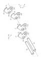
図1に示すように、可動体移動装置11は、互いに噛合可能な一対のチェーン部材12a,12bを有するとともにその長手方向に沿って進退移動可能な噛合チェーン12と、噛合チェーン12の基端側に固定状態で配置される収容部13と、噛合チェーン12の先端側の端部にジョイントリンク14を介して連結された可動体15とを備えている。Hereinafter, an embodiment of a movable body moving apparatus will be described with reference to the drawings.
As shown in FIG. 1, the movable
なお、以下の記載では、可動体15を移動させる際の噛合チェーン12の進退移動方向をZとする。この場合、噛合チェーン12の進行方向(図1では上方向)をZ1とし、噛合チェーン12の退行方向(図1では下方向)をZ2とする。また、進退移動方向Zと直交する方向のうち、対をなすチェーン部材12a,12b同士が相互に噛み合って一体化した噛合状態にある噛合チェーン12が退行方向への移動に伴いチェーン部材12a,12b同士を相互に噛み外れさせて分岐させる方向を分岐方向X(図1では左右方向)とする。さらに、進退移動方向Z及び分岐方向Xの両方と直交する方向を前後方向Y(図1では紙面と直交する方向)とする。そして、図1及び図2では、収容部13の外装の図示を省略して、収容部13の内部構成を図示している。 In the following description, the forward / backward moving direction of the
図1に示すように、収容部13は、噛合チェーン12を収容可能に構成されている。収容部13内における分岐方向Xの中央部には、前後方向Yに延びる軸線を中心に正逆両方向に回転可能なスプロケット16が片方のチェーン部材12b(噛合チェーン12)と噛み合うように設けられている。スプロケット16は、図示しないモーターによって正逆両方向に回転駆動される。そして、このスプロケット16の回転駆動に伴って噛合チェーン12は進退移動方向Zに沿って進退移動する。 As shown in FIG. 1, the
さらに、収容部13は、前後方向Yにおいて外装(図示略)と略同一の矩形状をなす誘導板17を備えている。誘導板17の内側面には、噛合状態から分岐した一対のチェーン部材12a,12bが渦巻きながら移動するように、一対のチェーン部材12a,12bを誘導可能な渦巻状の部分を有する一対の誘導溝18が図1においてほぼ左右対称となるように設けられている。 Further, the
また、収容部13において、外装(図示略)の内側面には、誘導板17の一対の誘導溝18と対応するように一対の誘導溝18が設けられている。したがって、収容部13の前後方向Yにおける両内側面には、一対の誘導溝18同士がそれぞれ対向するように設けられている。なお、収容部13における進行方向Z1側の面における分岐方向Xのほぼ中央部には、噛合チェーン12を通すための開口部19が形成されている。 In the
図3及び図4に示すように、本実施形態において、噛合チェーン12を構成する一対のチェーン部材12a,12bには、一列のチェーン部材が採用されている。そして、一対のチェーン部材12a,12bは、進退移動方向Zに沿った直列方向へ順次に直列に連結されるリンクプレートの一例としての複数対の内プレート21と、リンクプレートの一例としての複数対の外プレート22とをそれぞれ有している。 As shown in FIGS. 3 and 4, in this embodiment, a pair of
内プレート21及び外プレート22は、互いに同じ構成になっており、それぞれ鉤状の爪部25を有している。すなわち、一対のチェーン部材12a,12bのうち一方のチェーン部材12aの各外プレート22及び各内プレート21における進行方向Z1側と、他方のチェーン部材12bの各外プレート22及び各内プレート21における退行方向Z2側には、互いに噛合可能な爪部25がそれぞれ形成されている。 The
つまり、爪部25は、一対のチェーン部材12a,12bの各外プレート22及び各内プレート21における進退移動方向Zの一方側に形成されている。そして、一対のチェーン部材12a,12b同士は、各外プレート22の爪部25及び各内プレート21の爪部25においてそれぞれ噛合する。 That is, the
さらに、各内プレート21及び各外プレート22には、円形状の一対のピン孔23a,23bが、チェーン部材12a,12bの進退移動方向Zに沿った直列方向に並んで配置されるように貫通して形成されている。一対のピン孔23a,23bは互いに大きさが異なっている。本実施形態の各内プレート21及び各外プレート22では、ピン孔23aの方がピン孔23bよりも若干小さくなっており、この小さい方のピン孔23aが爪部25側に配置されている。 Further, each
さらに、一対のチェーン部材12a,12bは、直列方向で端部同士が重なって隣り合う各対の内プレート21と各対の外プレート22とを一対のピン孔23a,23bにおいて回動自在に直列に連結する円柱状の連結ピン24を有している。連結ピン24は、一対のピン孔23a,23bのうちの小さい方のピン孔23aに密嵌され且つ大きい方のピン孔23bに遊嵌される。 Further, the pair of
すなわち、連結ピン24は、一対のピン孔23a,23bのうちの小さい方のピン孔23aに対して回動不能に嵌合され且つ大きい方のピン孔23bに対して回動可能に嵌合される。この場合、各内プレート21及び各外プレート22における一対のピン孔23a,23bのうち連結ピン24が密嵌される方のピン孔23aは爪部25側に配置される。 That is, the connecting
なお、本実施形態の一対のチェーン部材12a,12bは、ブシュやローラを必要とすることなく、連結ピン24と、互いに同一構成の内プレート21及び外プレート22とによって構成されている。すなわち、一対のチェーン部材12a,12bは、2種類の部品のみで構成されている。 Note that the pair of
また、連結ピン24の両端部は、前後方向Yにおいて外プレート22よりも外側に突出している。そして、一対のチェーン部材12a,12bが収容部13内に収容される際には、それらの連結ピン24の両端部が収容部13内にて前後方向Yで対向するそれぞれの一対の誘導溝18に摺動可能に挿入される。 Further, both end portions of the connecting
すなわち、一対のチェーン部材12a,12bが収容部13内に収容される際には、各連結ピン24の一端部が収容部13の誘導板17に設けられた誘導溝18に挿入され、各連結ピン24の他端部が収容部13の外装(図示略)の内側面に設けられた誘導溝18に挿入される。 That is, when the pair of
そして、噛合チェーン12は、図1に示すように、一対のチェーン部材12a,12bの進行方向Z1への移動に伴って一対のチェーン部材12a,12b間で対応する外プレート22の爪部25同士及び内プレート21の爪部25同士がそれぞれ相互に噛み合うことで直棒状に一体化した剛体構造の噛合状態となる。一方、噛合チェーン12は、図2に示すように、その噛合状態から一対のチェーン部材12a,12bの退行方向Z2への移動に伴って相互に噛み外れることで分岐方向Xに分岐されて大部分が収容部13内に収容される。なお、一対のチェーン部材12a,12bにおける互いに噛合する外プレート22同士と互いに噛合する内プレート21同士とは、進退移動方向Zに並ぶ連結ピン24の1ピッチ分だけ位置がずれている。 As shown in FIG. 1, the meshing
また、図1及び図2に示すように、噛合チェーン12は、長手方向における進行方向Z1側の端部が可動体15に連結されている。可動体15には各種の機能部材(例えば、昇降テーブルやクレーンなど)が取り付けられるようになっている。そして、噛合チェーン12の進退移動に伴って可動体15が進退移動方向Zへ移動すると、可動体15に取り付けられた機能部材も可動体15と一緒に進退移動方向Zへ移動する。 As shown in FIGS. 1 and 2, the meshing
次に、可動体移動装置11において、一対のチェーン部材12a,12bの進行方向Z1への移動に伴って相互に噛み合うことで、噛合チェーン12が直棒状に一体化した剛体構造の噛合状態となるときの作用を説明する。 Next, in the movable
さて、一対のチェーン部材12a,12bを噛合させて噛合チェーン12を噛合状態とする場合には、まず、スプロケット16を図2において時計方向に回転駆動させる。すると、一対のチェーン部材12a,12bは、一対の誘導溝18により連結ピン24においてそれぞれガイドされながら進行方向Z1へ移動する。これにより、一対のチェーン部材12a,12bにおける互いに対応する外プレート22同士及び内プレート21同士がそれらの爪部25において交互に順次噛合し、図1に示すように、噛合チェーン12が噛合状態となる。 Now, when the pair of
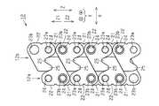
このとき、図5に示すように、噛合チェーン12は、進退移動方向Z及び連結ピン24の延びる方向である前後方向Yの両方と直交する方向である分岐方向Xにおいて対向する連結ピン24同士のピン孔23a,23bに対する嵌合状態が同じになる。すなわち、分岐方向Xにおいて対向する連結ピン24同士は、いずれもピン孔23aに密嵌しているか、いずれもピン孔23bに遊嵌しているかのどちらかになっている。 At this time, as shown in FIG. 5, the meshing
この場合、チェーン部材12aの外プレート22及び内プレート21の退行方向Z2側のピン孔23bと、当該外プレート22及び内プレート21に対して退行方向Z2側でそれぞれ隣り合うチェーン部材12bの外プレート22及び内プレート21の進行方向Z1側のピン孔23bとが分岐方向Xにおいて対向する。 In this case, the
一方、チェーン部材12aの外プレート22及び内プレート21の進行方向Z1側のピン孔23aと、当該外プレート22及び内プレート21に対して進行方向Z1側でそれぞれ隣り合うチェーン部材12bの外プレート22及び内プレート21の退行方向Z2側のピン孔23aとが分岐方向Xにおいて対向する。 On the other hand, the
このため、チェーン部材12aを構成する外プレート22及び内プレート21と、チェーン部材12bを構成する外プレート22及び内プレート21とを全て同じ構成(共通部品)にすることができる。したがって、一対のチェーン部材12a,12bを構成する部品の種類を低減でき、ひいては噛合チェーン12を構成する部品の種類を低減できる。 For this reason, all of the
また、噛合チェーン12が噛合状態にあるときには、一対のチェーン部材12a,12bの外プレート22の爪部25同士の噛合部分及び内プレート21の爪部25同士の噛合部分が、それぞれ分岐方向Xにおいて対向する2つのピン孔23aにそれぞれ密嵌された連結ピン24同士に挟まれた状態になる。このため、一対のチェーン部材12a,12bの外プレート22の爪部25同士の噛合状態及び内プレート21の爪部25同士の噛合状態がそれぞれ安定する。 Further, when the meshing
以上詳述した実施形態によれば、次のような効果が発揮される。
(1)噛合チェーン12において、一対のチェーン部材12a,12b同士が噛み合って一体化された噛合状態では、分岐方向Xにおいて対向する連結ピン24同士のピン孔23a,23bに対する嵌合状態が同じになっている。このため、チェーン部材12aを構成する外プレート22及び内プレート21と、チェーン部材12bを構成する外プレート22及び内プレート21とを全て同じ構成(共通部品)にすることができる。したがって、一対のチェーン部材12a,12bを構成する部品の種類を低減でき、ひいては噛合チェーン12を構成する部品の種類を低減できる。加えて、一対のチェーン部材12a,12bにおける外プレート22のピッチと内プレート21のピッチとの差が無くなるので、噛合チェーン12とスプロケット16との円滑な噛み合い状態を実現できる。According to the embodiment detailed above, the following effects are exhibited.
(1) In the meshing
(2)噛合チェーン12において、一対のチェーン部材12a,12b同士は、外プレート22の爪部25及び内プレート21の爪部25において噛合し、外プレート22及び内プレート21における一対のピン孔23a,23bのうち連結ピン24が密嵌される方のピン孔23aは爪部25側に配置されている。このため、一対のチェーン部材12a,12bの外プレート22の爪部25同士の噛合状態及び内プレート21の爪部25同士の噛合状態をそれぞれ安定させることができる。 (2) In the meshing
(3)噛合チェーン12において、一対のチェーン部材12a,12bは、連結ピン24と、互いに同一構成の外プレート22及び内プレート21とによって構成されている。このため、一対のチェーン部材12a,12bを2種類の部品だけで構成することができるので、一対のチェーン部材12a,12bの構造を簡単にすることができる。 (3) In the meshing
(4)噛合チェーン12は、その構成にブシュを用いていない。このため、ブシュを用いた噛合チェーンに比べて、ブシュの分だけ部品点数を低減できるとともに軽量化を図ることができる。したがって、水平方向と進退移動方向Zとが一致する態様で可動体移動装置11を使用した場合の噛合チェーン12の自重による撓み量を低減できる。この結果、噛合チェーン12のストローク(進退移動距離)を、ブシュを用いた噛合チェーンに比べて長くすることができる。加えて、噛合チェーン12はブシュを用いていないので、ブシュと連結ピンとの接触音をなくすことができる。このため、ブシュを用いた噛合チェーンに比べて使用時の騒音を低減することができる。 (4) The meshing
(変更例)
なお、上記実施形態は次のように変更してもよい。
・図6に示すように、噛合チェーン12の噛合状態において、一対のチェーン部材12a,12bの各内プレート21及び各外プレート22における一対のピン孔23a,23bのうち連結ピン24が遊嵌される方のピン孔23aを爪部25側に配置してもよい。この場合、チェーン部材12aの外プレート22及び内プレート21の進行方向Z1側のピン孔23bと、当該外プレート22及び内プレート21に対して進行方向Z1側でそれぞれ隣り合うチェーン部材12bの外プレート22及び内プレート21の退行方向Z2側のピン孔23bとが分岐方向Xにおいて対向する。一方、チェーン部材12aの外プレート22及び内プレート21の退行方向Z2側のピン孔23aと、当該外プレート22及び内プレート21に対して退行方向Z2側でそれぞれ隣り合うチェーン部材12bの外プレート22及び内プレート21の進行方向Z1側のピン孔23aとが分岐方向Xにおいて対向する。さらにこの場合、一対のチェーン部材12a,12bの外プレート22の爪部25同士の噛合部分及び内プレート21の爪部25同士の噛合部分が、それぞれ分岐方向Xにおいて対向する2つのピン孔23bにそれぞれ遊嵌された連結ピン24同士に挟まれた状態になる。このため、一対のチェーン部材12a,12bの各内プレート21の爪部25同士及び各外プレート22の爪部25同士が噛合する際のずれを吸収することができる。(Example of change)
In addition, you may change the said embodiment as follows.
As shown in FIG. 6, in the meshed state of the meshing
・噛合チェーン12は、連結ピン24が挿通されるローラを備えていてもよい。
・噛合チェーン12を構成するチェーン部材12a,12bは二列以上のチェーン部材であってもよい。The meshing
The
・噛合チェーン12は、二対以上のチェーン部材12a,12bによって構成してもよい。
・可動体移動装置11は何れの向きに配置してもよい。例えば、進退移動方向Zが水平方向と一致するように可動体移動装置11を配置してもよいし、進退移動方向Zが水平方向と交差するように可動体移動装置11を配置してもよい。The meshing
The movable
11…可動体移動装置、12…噛合チェーン、12a,12b…チェーン部材、15…可動体、21…リンクプレートの一例としての内プレート、22…リンクプレートの一例としての外プレート、23a,23b…ピン孔、24…連結ピン、25…爪部、Z…進退移動方向、Z1…進行方向、Z2…退行方向。 DESCRIPTION OF
Claims (5)
Translated fromJapanese前記チェーン部材は、一対のピン孔を有した複数のリンクプレート同士が前記一対のピン孔において直列に連結ピンによって回動自在に連結され、
前記チェーン部材を構成する複数の前記リンクプレートの前記一対のピン孔は、それぞれ前記チェーン部材の進退移動方向に並んで配置されるとともに、互いに大きさが異なり、
前記連結ピンは、前記一対のピン孔のうちの小さい方の前記ピン孔に密嵌され且つ大きい方の前記ピン孔に遊嵌され、
前記チェーン部材同士が噛み合って一体化された状態では、前記進退移動方向及び前記連結ピンの延びる方向の両方と直交する方向において対向する前記連結ピン同士の前記ピン孔に対する嵌合状態が同じになることを特徴とする噛合チェーン。It has at least a pair of chain members that can move forwards and backwards, and the chain members that make a pair move in the direction of travel to mesh with each other and integrate, while the chain members retreat from the integrated meshing state. A meshing chain that diverges and branches by moving in the direction,
In the chain member, a plurality of link plates having a pair of pin holes are rotatably connected by a connecting pin in series in the pair of pin holes,
The pair of pin holes of the plurality of link plates constituting the chain member are arranged side by side in the forward / backward movement direction of the chain member, and have different sizes from each other,
The connecting pin is tightly fitted into the smaller pin hole of the pair of pin holes and loosely fitted into the larger pin hole,
In a state where the chain members are engaged with each other and integrated, the fitting state of the connecting pins facing each other in the direction orthogonal to both the forward / backward moving direction and the extending direction of the connecting pins is the same. A meshing chain characterized by that.
前記各リンクプレートにおける前記一対のピン孔のうち前記連結ピンが密嵌される方は前記爪部側に配置されることを特徴とする請求項1に記載の噛合チェーン。Each pair of chain members meshes with each other at a claw portion formed on one side of the forward / backward movement direction in the link plate,
2. The meshing chain according to claim 1, wherein one of the pair of pin holes in each of the link plates to which the connecting pin is closely fitted is disposed on the claw portion side.
前記各リンクプレートにおける前記一対のピン孔のうち前記連結ピンが遊嵌される方は前記爪部側に配置されることを特徴とする請求項1に記載の噛合チェーン。Each pair of chain members meshes with each other at a claw portion formed on one side of the forward / backward movement direction in the link plate,
2. The meshing chain according to claim 1, wherein, of the pair of pin holes in each link plate, the one in which the connecting pin is loosely fitted is disposed on the claw portion side.
Priority Applications (7)
| Application Number | Priority Date | Filing Date | Title |
|---|---|---|---|
| JP2016031145AJP6078672B1 (en) | 2016-02-22 | 2016-02-22 | Meshing chain and movable body moving device |
| CN201780002343.3ACN107848779B (en) | 2016-02-22 | 2017-02-14 | Engagement chain and movable body mobile device |
| KR1020187005388AKR101929722B1 (en) | 2016-02-22 | 2017-02-14 | Engaging chain and movable body moving device |
| EP17756315.2AEP3421410B1 (en) | 2016-02-22 | 2017-02-14 | Engagement chain and movable body movement device |
| PCT/JP2017/005380WO2017145875A1 (en) | 2016-02-22 | 2017-02-14 | Engagement chain and movable body movement device |
| US15/743,007US10295018B2 (en) | 2016-02-22 | 2017-02-14 | Engagement chain and movable body movement device |
| TW106105169ATWI614426B (en) | 2016-02-22 | 2017-02-17 | Engagement chain and movable body moving device |
Applications Claiming Priority (1)
| Application Number | Priority Date | Filing Date | Title |
|---|---|---|---|
| JP2016031145AJP6078672B1 (en) | 2016-02-22 | 2016-02-22 | Meshing chain and movable body moving device |
Publications (2)
| Publication Number | Publication Date |
|---|---|
| JP6078672B1true JP6078672B1 (en) | 2017-02-08 |
| JP2017149505A JP2017149505A (en) | 2017-08-31 |
Family
ID=57981555
Family Applications (1)
| Application Number | Title | Priority Date | Filing Date |
|---|---|---|---|
| JP2016031145AActiveJP6078672B1 (en) | 2016-02-22 | 2016-02-22 | Meshing chain and movable body moving device |
Country Status (7)
| Country | Link |
|---|---|
| US (1) | US10295018B2 (en) |
| EP (1) | EP3421410B1 (en) |
| JP (1) | JP6078672B1 (en) |
| KR (1) | KR101929722B1 (en) |
| CN (1) | CN107848779B (en) |
| TW (1) | TWI614426B (en) |
| WO (1) | WO2017145875A1 (en) |
Cited By (1)
| Publication number | Priority date | Publication date | Assignee | Title |
|---|---|---|---|---|
| CN114502858A (en)* | 2019-10-09 | 2022-05-13 | 株式会社椿本链条 | Meshing chain and movable body moving device |
Families Citing this family (9)
| Publication number | Priority date | Publication date | Assignee | Title |
|---|---|---|---|---|
| DE202016105840U1 (en)* | 2016-10-18 | 2017-11-23 | Igus Gmbh | High-speed lifting device with supply line and energy supply chain for this purpose |
| FR3072374B1 (en)* | 2017-10-17 | 2022-12-30 | Serapid France | LIFTING DEVICE BY PUSH |
| KR102399871B1 (en)* | 2017-11-08 | 2022-05-20 | 삼성전자 주식회사 | Robot arm extension apparatus and robot including the same |
| JP6597851B1 (en)* | 2018-08-07 | 2019-10-30 | 株式会社椿本チエイン | Meshing chain and movable body moving device |
| JP6597852B1 (en)* | 2018-08-07 | 2019-10-30 | 株式会社椿本チエイン | Meshing chain and movable body moving device |
| EP3782929A1 (en)* | 2019-08-23 | 2021-02-24 | Jungheinrich Aktiengesellschaft | Container stacking picking cart |
| DE102020130186A1 (en)* | 2020-11-16 | 2022-05-19 | Paul Hettich Gmbh & Co. Kg | Household appliance with a storage container |
| DE102021115101A1 (en) | 2021-06-11 | 2022-12-15 | Iwis Antriebssysteme Gmbh & Co. Kg | CHAIN DEPOT |
| EP4497972A1 (en)* | 2023-07-28 | 2025-01-29 | ABB E-mobility B.V. | Belt actuator system |
Citations (8)
| Publication number | Priority date | Publication date | Assignee | Title |
|---|---|---|---|---|
| JPH08169693A (en)* | 1994-12-19 | 1996-07-02 | Sanin Booruto Seisakusho:Kk | Extendedly paying-out device for band |
| JP2001241211A (en)* | 2000-02-25 | 2001-09-04 | Matsushita Electric Works Ltd | Expansible pole |
| US20060219144A1 (en)* | 2005-01-20 | 2006-10-05 | Michael Phelan | Telescoping mast having variable height locking and a chain erection mechanism with a cable management system |
| JP2008256202A (en)* | 2007-03-13 | 2008-10-23 | Moritoshi Kondou | Expansion device |
| JP2009001377A (en)* | 2007-06-21 | 2009-01-08 | Tsubakimoto Chain Co | Engagement chain type hoisting and lowering device |
| US20090026018A1 (en)* | 2007-07-26 | 2009-01-29 | Production Resource Group L.L.C | Self Erecting Zipper Lift |
| JP2013057332A (en)* | 2011-09-07 | 2013-03-28 | Sr Engineering Co Ltd | Delivery device of chain |
| KR20150079507A (en)* | 2015-06-10 | 2015-07-08 | 이상용 | Zipper-type chain units having a truss structure |
Family Cites Families (14)
| Publication number | Priority date | Publication date | Assignee | Title |
|---|---|---|---|---|
| US3645146A (en)* | 1969-09-29 | 1972-02-29 | Tony Nagin | Interlocking chain structure |
| JPH07223800A (en)* | 1994-02-10 | 1995-08-22 | Ochiai Nekusasu:Kk | Article elevating device |
| WO1996019405A1 (en)* | 1994-12-19 | 1996-06-27 | Sanin Boruto Seisakujo Co., Ltd. | Rod-shaped extension body |
| JP3370928B2 (en)* | 1998-03-30 | 2003-01-27 | 株式会社椿本チエイン | Lifting device using meshing chain |
| JP4723538B2 (en)* | 2007-06-21 | 2011-07-13 | 株式会社椿本チエイン | Engagement chain type lifting device |
| JP5340670B2 (en) | 2008-08-22 | 2013-11-13 | 株式会社椿本チエイン | Engagement multi-row chain for lifting drive |
| CN101407306A (en)* | 2008-11-14 | 2009-04-15 | 丰华 | Stacked flexible rack gear type elevating gear |
| JP4662503B2 (en) | 2008-12-09 | 2011-03-30 | 株式会社椿本チエイン | Meshing chain |
| JP4662504B2 (en)* | 2009-03-09 | 2011-03-30 | 株式会社椿本チエイン | Engagement chain for lifting drive |
| JP4662507B1 (en) | 2009-11-05 | 2011-03-30 | 株式会社椿本チエイン | Meshing chain |
| JP5686607B2 (en)* | 2011-01-05 | 2015-03-18 | 株式会社椿本チエイン | Engagement chain unit for lifting drive |
| JP4875216B1 (en)* | 2011-05-12 | 2012-02-15 | 株式会社椿本チエイン | Meshing chain unit |
| JP2013092174A (en) | 2011-10-24 | 2013-05-16 | Tsubakimoto Chain Co | Engagement chain unit |
| JP5747055B2 (en) | 2013-06-04 | 2015-07-08 | 株式会社椿本チエイン | Movable body moving device |
- 2016
- 2016-02-22JPJP2016031145Apatent/JP6078672B1/enactiveActive
- 2017
- 2017-02-14USUS15/743,007patent/US10295018B2/enactiveActive
- 2017-02-14CNCN201780002343.3Apatent/CN107848779B/enactiveActive
- 2017-02-14KRKR1020187005388Apatent/KR101929722B1/enactiveActive
- 2017-02-14WOPCT/JP2017/005380patent/WO2017145875A1/ennot_activeCeased
- 2017-02-14EPEP17756315.2Apatent/EP3421410B1/enactiveActive
- 2017-02-17TWTW106105169Apatent/TWI614426B/enactive
Patent Citations (8)
| Publication number | Priority date | Publication date | Assignee | Title |
|---|---|---|---|---|
| JPH08169693A (en)* | 1994-12-19 | 1996-07-02 | Sanin Booruto Seisakusho:Kk | Extendedly paying-out device for band |
| JP2001241211A (en)* | 2000-02-25 | 2001-09-04 | Matsushita Electric Works Ltd | Expansible pole |
| US20060219144A1 (en)* | 2005-01-20 | 2006-10-05 | Michael Phelan | Telescoping mast having variable height locking and a chain erection mechanism with a cable management system |
| JP2008256202A (en)* | 2007-03-13 | 2008-10-23 | Moritoshi Kondou | Expansion device |
| JP2009001377A (en)* | 2007-06-21 | 2009-01-08 | Tsubakimoto Chain Co | Engagement chain type hoisting and lowering device |
| US20090026018A1 (en)* | 2007-07-26 | 2009-01-29 | Production Resource Group L.L.C | Self Erecting Zipper Lift |
| JP2013057332A (en)* | 2011-09-07 | 2013-03-28 | Sr Engineering Co Ltd | Delivery device of chain |
| KR20150079507A (en)* | 2015-06-10 | 2015-07-08 | 이상용 | Zipper-type chain units having a truss structure |
Cited By (2)
| Publication number | Priority date | Publication date | Assignee | Title |
|---|---|---|---|---|
| CN114502858A (en)* | 2019-10-09 | 2022-05-13 | 株式会社椿本链条 | Meshing chain and movable body moving device |
| CN114502858B (en)* | 2019-10-09 | 2024-05-14 | 株式会社椿本链条 | Meshing chain and movable body moving device |
Also Published As
| Publication number | Publication date |
|---|---|
| JP2017149505A (en) | 2017-08-31 |
| KR20180033264A (en) | 2018-04-02 |
| KR101929722B1 (en) | 2018-12-14 |
| US10295018B2 (en) | 2019-05-21 |
| EP3421410B1 (en) | 2020-11-11 |
| TWI614426B (en) | 2018-02-11 |
| CN107848779A (en) | 2018-03-27 |
| US20180216703A1 (en) | 2018-08-02 |
| EP3421410A1 (en) | 2019-01-02 |
| CN107848779B (en) | 2019-03-29 |
| WO2017145875A1 (en) | 2017-08-31 |
| EP3421410A4 (en) | 2019-10-16 |
| TW201736753A (en) | 2017-10-16 |
Similar Documents
| Publication | Publication Date | Title |
|---|---|---|
| JP6078672B1 (en) | Meshing chain and movable body moving device | |
| US8991275B2 (en) | Two-way push-pull chain and reciprocating actuator | |
| EP2708775B1 (en) | Engagement chain unit | |
| US9217497B2 (en) | Push chain, linear motion driving device and patient table | |
| JP5747055B2 (en) | Movable body moving device | |
| CA2563978A1 (en) | Push-pull chain and actuator | |
| JP2009243581A (en) | Chain transmission device | |
| JP6597851B1 (en) | Meshing chain and movable body moving device | |
| JP6597852B1 (en) | Meshing chain and movable body moving device | |
| JP5850803B2 (en) | Meshing chain unit, meshing chain type advance / retreat device | |
| JP2007205487A (en) | Forward/backward movement driving chain | |
| JP2016217406A (en) | Movable body moving device | |
| JP5425254B2 (en) | Engagement chain type advance / retreat actuator | |
| JP5864374B2 (en) | Engagement chain type advance / retreat actuator | |
| JP6673011B2 (en) | Interlocking chain and movable body moving device | |
| JP2010127396A (en) | Meshing chain | |
| JP6814861B1 (en) | Mating chain and movable body moving device | |
| JP4678230B2 (en) | Driving cord for moving body | |
| JP6163452B2 (en) | Connecting member, connecting method of chain member, meshing chain, and movable body moving device |
Legal Events
| Date | Code | Title | Description |
|---|---|---|---|
| TRDD | Decision of grant or rejection written | ||
| A01 | Written decision to grant a patent or to grant a registration (utility model) | Free format text:JAPANESE INTERMEDIATE CODE: A01 Effective date:20170110 | |
| A61 | First payment of annual fees (during grant procedure) | Free format text:JAPANESE INTERMEDIATE CODE: A61 Effective date:20170116 | |
| R150 | Certificate of patent or registration of utility model | Ref document number:6078672 Country of ref document:JP Free format text:JAPANESE INTERMEDIATE CODE: R150 |