JP6078335B2 - Substrate processing apparatus, semiconductor device manufacturing method, vaporization system, vaporizer, and program - Google Patents
Substrate processing apparatus, semiconductor device manufacturing method, vaporization system, vaporizer, and programDownload PDFInfo
- Publication number
- JP6078335B2 JP6078335B2JP2012286055AJP2012286055AJP6078335B2JP 6078335 B2JP6078335 B2JP 6078335B2JP 2012286055 AJP2012286055 AJP 2012286055AJP 2012286055 AJP2012286055 AJP 2012286055AJP 6078335 B2JP6078335 B2JP 6078335B2
- Authority
- JP
- Japan
- Prior art keywords
- liquid
- flow rate
- carrier gas
- gas
- gas supply
- Prior art date
- Legal status (The legal status is an assumption and is not a legal conclusion. Google has not performed a legal analysis and makes no representation as to the accuracy of the status listed.)
- Active
Links
Images


Classifications
- C—CHEMISTRY; METALLURGY
- C23—COATING METALLIC MATERIAL; COATING MATERIAL WITH METALLIC MATERIAL; CHEMICAL SURFACE TREATMENT; DIFFUSION TREATMENT OF METALLIC MATERIAL; COATING BY VACUUM EVAPORATION, BY SPUTTERING, BY ION IMPLANTATION OR BY CHEMICAL VAPOUR DEPOSITION, IN GENERAL; INHIBITING CORROSION OF METALLIC MATERIAL OR INCRUSTATION IN GENERAL
- C23C—COATING METALLIC MATERIAL; COATING MATERIAL WITH METALLIC MATERIAL; SURFACE TREATMENT OF METALLIC MATERIAL BY DIFFUSION INTO THE SURFACE, BY CHEMICAL CONVERSION OR SUBSTITUTION; COATING BY VACUUM EVAPORATION, BY SPUTTERING, BY ION IMPLANTATION OR BY CHEMICAL VAPOUR DEPOSITION, IN GENERAL
- C23C16/00—Chemical coating by decomposition of gaseous compounds, without leaving reaction products of surface material in the coating, i.e. chemical vapour deposition [CVD] processes
- C23C16/44—Chemical coating by decomposition of gaseous compounds, without leaving reaction products of surface material in the coating, i.e. chemical vapour deposition [CVD] processes characterised by the method of coating
- C23C16/448—Chemical coating by decomposition of gaseous compounds, without leaving reaction products of surface material in the coating, i.e. chemical vapour deposition [CVD] processes characterised by the method of coating characterised by the method used for generating reactive gas streams, e.g. by evaporation or sublimation of precursor materials
- C23C16/4481—Chemical coating by decomposition of gaseous compounds, without leaving reaction products of surface material in the coating, i.e. chemical vapour deposition [CVD] processes characterised by the method of coating characterised by the method used for generating reactive gas streams, e.g. by evaporation or sublimation of precursor materials by evaporation using carrier gas in contact with the source material
- C—CHEMISTRY; METALLURGY
- C23—COATING METALLIC MATERIAL; COATING MATERIAL WITH METALLIC MATERIAL; CHEMICAL SURFACE TREATMENT; DIFFUSION TREATMENT OF METALLIC MATERIAL; COATING BY VACUUM EVAPORATION, BY SPUTTERING, BY ION IMPLANTATION OR BY CHEMICAL VAPOUR DEPOSITION, IN GENERAL; INHIBITING CORROSION OF METALLIC MATERIAL OR INCRUSTATION IN GENERAL
- C23C—COATING METALLIC MATERIAL; COATING MATERIAL WITH METALLIC MATERIAL; SURFACE TREATMENT OF METALLIC MATERIAL BY DIFFUSION INTO THE SURFACE, BY CHEMICAL CONVERSION OR SUBSTITUTION; COATING BY VACUUM EVAPORATION, BY SPUTTERING, BY ION IMPLANTATION OR BY CHEMICAL VAPOUR DEPOSITION, IN GENERAL
- C23C16/00—Chemical coating by decomposition of gaseous compounds, without leaving reaction products of surface material in the coating, i.e. chemical vapour deposition [CVD] processes
- C23C16/44—Chemical coating by decomposition of gaseous compounds, without leaving reaction products of surface material in the coating, i.e. chemical vapour deposition [CVD] processes characterised by the method of coating
- C23C16/448—Chemical coating by decomposition of gaseous compounds, without leaving reaction products of surface material in the coating, i.e. chemical vapour deposition [CVD] processes characterised by the method of coating characterised by the method used for generating reactive gas streams, e.g. by evaporation or sublimation of precursor materials
- C23C16/4486—Chemical coating by decomposition of gaseous compounds, without leaving reaction products of surface material in the coating, i.e. chemical vapour deposition [CVD] processes characterised by the method of coating characterised by the method used for generating reactive gas streams, e.g. by evaporation or sublimation of precursor materials by producing an aerosol and subsequent evaporation of the droplets or particles
- C—CHEMISTRY; METALLURGY
- C23—COATING METALLIC MATERIAL; COATING MATERIAL WITH METALLIC MATERIAL; CHEMICAL SURFACE TREATMENT; DIFFUSION TREATMENT OF METALLIC MATERIAL; COATING BY VACUUM EVAPORATION, BY SPUTTERING, BY ION IMPLANTATION OR BY CHEMICAL VAPOUR DEPOSITION, IN GENERAL; INHIBITING CORROSION OF METALLIC MATERIAL OR INCRUSTATION IN GENERAL
- C23C—COATING METALLIC MATERIAL; COATING MATERIAL WITH METALLIC MATERIAL; SURFACE TREATMENT OF METALLIC MATERIAL BY DIFFUSION INTO THE SURFACE, BY CHEMICAL CONVERSION OR SUBSTITUTION; COATING BY VACUUM EVAPORATION, BY SPUTTERING, BY ION IMPLANTATION OR BY CHEMICAL VAPOUR DEPOSITION, IN GENERAL
- C23C16/00—Chemical coating by decomposition of gaseous compounds, without leaving reaction products of surface material in the coating, i.e. chemical vapour deposition [CVD] processes
- C23C16/44—Chemical coating by decomposition of gaseous compounds, without leaving reaction products of surface material in the coating, i.e. chemical vapour deposition [CVD] processes characterised by the method of coating
- C23C16/455—Chemical coating by decomposition of gaseous compounds, without leaving reaction products of surface material in the coating, i.e. chemical vapour deposition [CVD] processes characterised by the method of coating characterised by the method used for introducing gases into reaction chamber or for modifying gas flows in reaction chamber
- C23C16/45563—Gas nozzles
- C23C16/45578—Elongated nozzles, tubes with holes
- C—CHEMISTRY; METALLURGY
- C23—COATING METALLIC MATERIAL; COATING MATERIAL WITH METALLIC MATERIAL; CHEMICAL SURFACE TREATMENT; DIFFUSION TREATMENT OF METALLIC MATERIAL; COATING BY VACUUM EVAPORATION, BY SPUTTERING, BY ION IMPLANTATION OR BY CHEMICAL VAPOUR DEPOSITION, IN GENERAL; INHIBITING CORROSION OF METALLIC MATERIAL OR INCRUSTATION IN GENERAL
- C23C—COATING METALLIC MATERIAL; COATING MATERIAL WITH METALLIC MATERIAL; SURFACE TREATMENT OF METALLIC MATERIAL BY DIFFUSION INTO THE SURFACE, BY CHEMICAL CONVERSION OR SUBSTITUTION; COATING BY VACUUM EVAPORATION, BY SPUTTERING, BY ION IMPLANTATION OR BY CHEMICAL VAPOUR DEPOSITION, IN GENERAL
- C23C16/00—Chemical coating by decomposition of gaseous compounds, without leaving reaction products of surface material in the coating, i.e. chemical vapour deposition [CVD] processes
- C23C16/44—Chemical coating by decomposition of gaseous compounds, without leaving reaction products of surface material in the coating, i.e. chemical vapour deposition [CVD] processes characterised by the method of coating
- C23C16/52—Controlling or regulating the coating process
- H—ELECTRICITY
- H01—ELECTRIC ELEMENTS
- H01L—SEMICONDUCTOR DEVICES NOT COVERED BY CLASS H10
- H01L21/00—Processes or apparatus adapted for the manufacture or treatment of semiconductor or solid state devices or of parts thereof
- H01L21/02—Manufacture or treatment of semiconductor devices or of parts thereof
- H01L21/02104—Forming layers
- H01L21/02365—Forming inorganic semiconducting materials on a substrate
- H01L21/02612—Formation types
- H01L21/02617—Deposition types
- H01L21/0262—Reduction or decomposition of gaseous compounds, e.g. CVD
- H—ELECTRICITY
- H01—ELECTRIC ELEMENTS
- H01L—SEMICONDUCTOR DEVICES NOT COVERED BY CLASS H10
- H01L21/00—Processes or apparatus adapted for the manufacture or treatment of semiconductor or solid state devices or of parts thereof
- H01L21/02—Manufacture or treatment of semiconductor devices or of parts thereof
- H01L21/02104—Forming layers
- H01L21/02107—Forming insulating materials on a substrate
- H01L21/02109—Forming insulating materials on a substrate characterised by the type of layer, e.g. type of material, porous/non-porous, pre-cursors, mixtures or laminates
- H01L21/02112—Forming insulating materials on a substrate characterised by the type of layer, e.g. type of material, porous/non-porous, pre-cursors, mixtures or laminates characterised by the material of the layer
- H01L21/02123—Forming insulating materials on a substrate characterised by the type of layer, e.g. type of material, porous/non-porous, pre-cursors, mixtures or laminates characterised by the material of the layer the material containing silicon
- H01L21/02142—Forming insulating materials on a substrate characterised by the type of layer, e.g. type of material, porous/non-porous, pre-cursors, mixtures or laminates characterised by the material of the layer the material containing silicon the material containing silicon and at least one metal element, e.g. metal silicate based insulators or metal silicon oxynitrides
- H01L21/02159—Forming insulating materials on a substrate characterised by the type of layer, e.g. type of material, porous/non-porous, pre-cursors, mixtures or laminates characterised by the material of the layer the material containing silicon the material containing silicon and at least one metal element, e.g. metal silicate based insulators or metal silicon oxynitrides the material containing zirconium, e.g. ZrSiOx
Landscapes
- Chemical & Material Sciences (AREA)
- Engineering & Computer Science (AREA)
- General Chemical & Material Sciences (AREA)
- Chemical Kinetics & Catalysis (AREA)
- Materials Engineering (AREA)
- Mechanical Engineering (AREA)
- Metallurgy (AREA)
- Organic Chemistry (AREA)
- Manufacturing & Machinery (AREA)
- Physics & Mathematics (AREA)
- Condensed Matter Physics & Semiconductors (AREA)
- General Physics & Mathematics (AREA)
- Computer Hardware Design (AREA)
- Microelectronics & Electronic Packaging (AREA)
- Power Engineering (AREA)
- Dispersion Chemistry (AREA)
- Chemical Vapour Deposition (AREA)
Description
Translated fromJapanese本発明は、基板処理装置、半導体装置の製造方法、気化システム、気化器およびプログラムに関する。The present invention relates to a substrate processing apparatus, a method of manufacturing a semiconductor device, vaporization system relatesto avaporizer andprograms.
半導体装置の製造工程の一工程として、液体原料を用いて、基板上に成膜する技術が特許文献1に開示されている。液体原料を用いて成膜等の基板処理を行う際には、液体原料を気化させて気体状態とした原料ガスを用いることが行われている。液体原料を気化させるには、例えば、特許文献2に示すような気化器が好適に用いられる。 Patent Document 1 discloses a technique for forming a film on a substrate using a liquid raw material as one step of a semiconductor device manufacturing process. When substrate processing such as film formation is performed using a liquid source, a source gas that is vaporized by vaporizing the liquid source is used. In order to vaporize the liquid raw material, for example, a vaporizer as shown in
半導体装置の微細化により、ウエハ表面積が増加し、また、より深い溝への成膜等の処理が必要となってきており、液体原料の供給量を増加させることが要求されている。 As the semiconductor device is miniaturized, the surface area of the wafer is increased, and a process such as film formation in a deeper groove is required, and it is required to increase the supply amount of the liquid raw material.
本発明の主な目的は、液体原料の供給量を増加させることができる基板処理装置、半導体装置の製造方法、気化システム、気化器およびプログラムを提供することにある。The main purpose of the present invention, a substrate processing apparatus capable of increasing the supply amount of the liquid material, a method of manufacturing a semiconductor device, vaporization system is to provideavaporizer andprograms.
本発明の一態様によれば、
基板を収容する処理室と、
液体原料を気化する気化器と、前記気化器内に形成された気化室に接続され前記気化室内に前記液体原料を供給する液体原料供給ユニットと、前記液体原料供給ユニットとは独立して前記気化室に接続され前記気化室に前記キャリアガスを供給するキャリアガス供給ユニットと、を有し、前記処理室に気化ガスを供給する気化ガス供給系と、
前記気化ガス供給系を制御して、前記液体原料供給ユニットおよび前記キャリアガス供給ユニットからそれぞれ前記液体原料および前記キャリアガスを前記気化室に供給し、前記キャリアガスの流量が5slm以上、前記気化室内における全圧に対する前記液体原料の分圧が1.8%以下となるよう前記液体原料の流量および前記キャリアガスの流量を調整するように構成される制御部と
を有する基板処理装置が提供される。According to one aspect of the invention,
A processing chamber for accommodating the substrate;
A vaporizer that vaporizes aliquid material; a liquid material supply unit that is connected to a vaporization chamber formed in the vaporizer and that supplies the liquid material into the vaporization chamber; and the vaporization material is independent of the liquid material supply unit. A carrier gas supply unit connected to a chamber for supplying the carrier gas to the vaporization chamber, and a vaporized gas supply system for supplying a vaporized gas to the processing chamber,
Wherein by controlling a vaporized gas supply system, the liquid material supply unit and the each of the liquid material and the carrier gas from the carrier gas supply unit wassubjected sheetbefore Symbol vaporization chamber,the flow rate of the carrier gas is more than 5 slm, the And a control unit configuredto adjust the flow rate of the liquid material and the flow rate of the carrier gas so that the partial pressure of the liquid material with respect to the total pressure in the vaporization chamber is1.8 % or less. Is done.
本発明の他の態様によれば、
気化器の気化室内に液体原料とキャリアガスとをそれぞれ独立した液体原料ガス供給ユニットおよびキャリアガス供給ユニットから供給し、前記キャリアガスの流量が5slm以上、前記気化室内における全圧に対する前記液体原料の分圧が1.8%以下となるよう前記液体原料の流量および前記キャリアガスの流量を調整し、前記液体原料を気化して気化ガスとする工程と、
前記気化ガスを基板が収容された処理室に供給して、基板を処理する工程と、
を有する半導体装置の製造方法が提供される。According to another aspect of the invention,
Aliquid source and a carrier gas are supplied from an independent liquid source gas supply unit and a carrier gas supply unit to the vaporization chamber of the vaporizer, and the flow rate of the carrier gas is 5 slm or more, and the liquid source with respect to the total pressure in the vaporization chamberAdjusting the flow rate of the liquid raw material and the flow rate of the carrier gas so that the partial pressure is1.8 % or less, evaporating the liquid raw material into a vaporized gas;
Supplying the vaporized gas to a processing chamber in which a substrate is accommodated, and processing the substrate;
A method of manufacturing a semiconductor device having the above is provided.
本発明のさらに他の態様によれば、
内部に形成された気化室内に液体原料とキャリアガスとをそれぞれ独立した液体原料ガス供給ユニットおよびキャリアガス供給ユニットから供給し、前記キャリアガスの流量が5slm以上、前記気化室内における全圧に対する前記液体原料の分圧が1.8%以下となるよう前記液体原料の流量および前記キャリアガスの流量を調整し、前記液体原料を気化する気化器と、ガスフィルタと、ミストフィルタを有する気化システムが提供される。
本発明のさらに他の態様によれば、
内部に形成された気化室内に液体原料とキャリアガスとをそれぞれ独立した液体原料ガス供給ユニットおよびキャリアガス供給ユニットから供給し、前記キャリアガスの流量が5slm以上、前記気化室内における全圧に対する前記液体原料の分圧が1.8%以下となるよう前記液体原料の流量および前記キャリアガスの流量を調整し、前記液体原料を気化する気化器が提供される。According to yet another aspect of the invention,
The liquid source and the carrier gas are supplied from an independent liquid source gas supply unit and a carrier gas supply unit into a vaporization chamber formed inside, and the flow rate of the carrier gas is 5 slm or more, and the liquid with respect to the total pressure in the vaporization chamber Provided is a vaporizer, a gas filter, and a vaporization system having a mist filter foradjusting the flowrate of the liquid material and the flow rate of the carrier gas so that the partial pressure of the raw material is1.8 % or less, and vaporizing the liquid material. Is done.
According to yet another aspect of the invention,
The liquid source and the carrier gas are supplied from an independent liquid source gas supply unit and a carrier gas supply unit into a vaporization chamber formed inside, and the flow rate of the carrier gas is 5 slm or more, and the liquid with respect to the total pressure in the vaporization chamber A vaporizer for vaporizing the liquid material by adjusting the flow rate of the liquid material and the flow rate of the carrier gas so that the partial pressure of the material is 1.8% or less is provided.
本発明のさらに他の態様によれば、
気化器を加熱する手順と、
気化器の気化室内に液体原料とキャリアガスとをそれぞれ独立した液体原料ガス供給ユニットおよびキャリアガス供給ユニットから供給し、前記キャリアガスの流量が5slm以上、前記気化室内における全圧に対する前記液体原料の分圧が1.8%以下となるよう前記液体原料の流量および前記キャリアガスの流量を調整する手順と、
を行うことで、液体原料を気化する手順をコンピュータにより基板処理装置に実行させるプログラムが提供される。According to yet another aspect of the invention,
A procedure for heating the vaporizer;
A liquid source and a carrier gas are supplied from an independent liquid source gas supply unit and a carrier gas supply unit to the vaporization chamber of the vaporizer, and the flow rate of the carrier gas is 5 slm or more, and the liquid source with respect to the total pressure in the vaporization chamberAdjusting the flowrate of the liquid raw material and the flow rate of the carrier gas so that the partial pressure is1.8 % or less;
By performing the above, a program for causing thesubstrate processing apparatus to execute a procedure for vaporizing the liquid raw material by a computer is provided.
本発明のさらに他の態様によれば、
基板を収容する処理室と、
液体原料を気化する気化器と、前記気化器内に形成された気化室に接続され前記気化室内に前記液体原料を供給する液体原料供給ユニットと、前記液体原料供給ユニットとは独立して前記気化室に接続され前記気化室に前記キャリアガスを供給するキャリアガス供給ユニットと、を有し、前記処理室に気化ガスを供給する気化ガス供給系と、
前記気化ガス供給系を制御して、前記液体原料供給ユニットおよび前記キャリアガス供給ユニットからそれぞれ前記液体原料および前記キャリアガスを前記気化室に供給し、前記キャリアガスの流量が5slm以上、前記気化室内における前記液体原料の分圧に対する前記液体原料の飽和蒸気圧の割合が12以上となるよう前記液体原料の流量および前記キャリアガスの流量を調整するように構成される制御部と、
を有する基板処理装置が提供される。
本発明のさらに他の態様によれば、
気化器の気化室内に液体原料とキャリアガスとをそれぞれ独立した液体原料ガス供給ユニットおよびキャリアガス供給ユニットから供給し、前記キャリアガスの流量が5slm以上、前記気化室内における前記液体原料の分圧に対する前記液体原料の飽和蒸気圧の割合が12以上となるよう前記液体原料の流量および前記キャリアガスの流量を調整し、前記液体原料を気化して気化ガスとする工程と、
前記気化ガスを基板が収容された処理室に供給して、前記基板を処理する工程と、
を有する半導体装置の製造方法が提供される。
本発明のさらに他の態様によれば、
内部に形成された気化室内に液体原料とキャリアガスとをそれぞれ独立した液体原料ガス供給ユニットおよびキャリアガス供給ユニットから供給し、前記キャリアガスの流量が5slm以上、前記気化室内における前記液体原料の分圧に対する前記液体原料の飽和蒸気圧の割合が12以上となるよう前記液体原料の流量および前記キャリアガスの流量を調整し、前記液体原料を気化する気化器と、ガスフィルタと、ミストフィルタを有する気化システムが提供される。
本発明のさらに他の態様によれば、
内部に形成された気化室内に液体原料とキャリアガスとをそれぞれ独立した液体原料ガス供給ユニットおよびキャリアガス供給ユニットから供給し、前記キャリアガスの流量が5slm以上、前記気化室内における前記液体原料の分圧に対する前記液体原料の飽和蒸気圧の割合が12以上となるよう前記液体原料の流量および前記キャリアガスの流量を調整し、前記液体原料を気化する気化器が提供される。
本発明のさらに他の態様によれば、
気化器を加熱する手順と、
気化器の気化室内に液体原料とキャリアガスとをそれぞれ独立した液体原料ガス供給ユニットおよびキャリアガス供給ユニットから供給し、前記キャリアガスの流量が5slm以上、前記気化室内における前記液体原料の分圧に対する前記液体原料の飽和蒸気圧の割合が12以上となるよう前記液体原料の流量および前記キャリアガスの流量を調整する手順と、
を行うことで、液体原料を気化する手順をコンピュータにより基板処理装置に実行させるプログラムが提供される。According to yet another aspect of the invention,
A processing chamber for accommodating the substrate;
A vaporizer that vaporizes a liquid material; a liquid material supply unit that is connected to a vaporization chamber formed in the vaporizer and that supplies the liquid material into the vaporization chamber; and the vaporization material is independent of the liquid material supply unit. A carrier gas supply unit connected to a chamber for supplying the carrier gas to the vaporization chamber, and a vaporized gas supply system for supplying a vaporized gas to the processing chamber,
The vaporized gas supply system is controlled to supply the liquid material and the carrier gas from the liquid material supply unit and the carrier gas supply unit to the vaporization chamber, respectively, and the flow rate of the carrier gas is 5 slm or more, A control unit configured to adjust the flow rate of the liquid source and the flow rate of the carrier gas so that the ratio of the saturated vapor pressure of the liquid source to the partial pressure of the liquid source is 12 or more;
A substrate processing apparatus is provided.
According to yet another aspect of the invention,
A liquid source and a carrier gas are supplied from an independent liquid source gas supply unit and a carrier gas supply unit to the vaporization chamber of the vaporizer, respectively, and the flow rate of the carrier gas is 5 slm or more, with respect to the partial pressure of the liquid source in the vaporization chamber Adjusting the flow rate of the liquid material and the flow rate of the carrier gas so that the ratio of the saturated vapor pressure of the liquid material is 12 or more, and evaporating the liquid material to form a vaporized gas;
Supplying the vaporized gas to a processing chamber in which a substrate is accommodated, and processing the substrate;
A method of manufacturing a semiconductor device having the above is provided.
According to yet another aspect of the invention,
A liquid source and a carrier gas are supplied from an independent liquid source gas supply unit and a carrier gas supply unit into a vaporization chamber formed therein, and the flow rate of the carrier gas is 5 slm or more. A liquid vaporizer for vaporizing the liquid raw material, a gas filter, and a mist filter by adjusting the flow rate of the liquid raw material and the flow rate of the carrier gas so that the ratio of the saturated vapor pressure of the liquid raw material to the pressure is 12 or more A vaporization system is provided.
According to yet another aspect of the invention,
A liquid source and a carrier gas are supplied from an independent liquid source gas supply unit and a carrier gas supply unit into a vaporization chamber formed therein, and the flow rate of the carrier gas is 5 slm or more. A vaporizer for vaporizing the liquid source is provided by adjusting the flow rate of the liquid source and the flow rate of the carrier gas so that the ratio of the saturated vapor pressure of the liquid source to the pressure is 12 or more.
According to yet another aspect of the invention,
A procedure for heating the vaporizer;
A liquid source and a carrier gas are supplied from an independent liquid source gas supply unit and a carrier gas supply unit to the vaporization chamber of the vaporizer, respectively, and the flow rate of the carrier gas is 5 slm or more, with respect to the partial pressure of the liquid source in the vaporization chamber Adjusting the flow rate of the liquid material and the flow rate of the carrier gas so that the saturated vapor pressure ratio of the liquid material is 12 or more;
By performing the above, a program for causing the substrate processing apparatus to execute a procedure for vaporizing the liquid raw material by a computer is provided.
本発明によれば、液体原料の供給量を増加させることができる。 According to the present invention, the supply amount of the liquid raw material can be increased.
次に、本発明の好ましい実施の形態について説明する。 Next, a preferred embodiment of the present invention will be described.
液体原料の供給量を増加させるためには、液体原料の供給時間を長くすることが考えられる。しかしながら、原料供給時間を長くすると、成膜等の基板処理時間が長くなり、半導体装置の生産性が著しく低下してしまう。成膜等の基板処理時間を短くするためには、液体原料の1回当たりの気化量を多くし短時間に成膜することが好ましい。 In order to increase the supply amount of the liquid raw material, it is conceivable to increase the supply time of the liquid raw material. However, if the raw material supply time is increased, the substrate processing time for film formation and the like is increased, and the productivity of the semiconductor device is significantly reduced. In order to shorten the substrate processing time such as film formation, it is preferable to increase the amount of vaporization of the liquid raw material per time and form the film in a short time.
しかし、従来の気化条件(希釈用のN2ガス流量:25slm、N2キャリアガス流量:1slm、液体流量:0.3g/min(希釈用のN2ガス流量、N2キャリアガス流量、液体流量については、後に説明する))のままで、液体流量のみを大きくして液体原料を多く供給しても、液体原料を十分に気化できず、気化室内に気化不良となった液体原料が残り、液体原料の熱分解生成物や重合物が気化室内部に堆積し、異物の発生や閉塞といった問題が発生する。However, conventional vaporization conditions (dilution N2 gas flow rate: 25 slm, N2 carrier gas flow rate: 1 slm, liquid flow rate: 0.3 g / min (dilution N2 gas flow rate, N2 carrier gas flow rate, liquid flow rate) Will be explained later))) Even if only the liquid flow rate is increased and a large amount of liquid raw material is supplied, the liquid raw material cannot be sufficiently vaporized, and the liquid raw material that has been poorly vaporized remains in the vaporization chamber. Thermal decomposition products and polymers of the liquid raw material accumulate in the vaporization chamber, causing problems such as generation of foreign substances and blockage.
液体原料の気化量を多くするための他の方法として、気化室内の圧力を低くするために希釈N2流量を低下させることが考えられる。しかしながら、縦型バッチ成膜装置等の複数の基板を同時に処理する装置では、膜厚均一性等の基板処理均一性の確保のため供給管内のN2ガス流量を低下させることができず、気化量を多くすることができない。As another method for increasing the vaporization amount of the liquid raw material, it is conceivable to reduce the flow rate of diluted N2 in order to reduce the pressure in the vaporization chamber. However, in an apparatus that simultaneously processes a plurality of substrates such as a vertical batch film forming apparatus, the N2 gas flow rate in the supply pipe cannot be reduced in order to ensure substrate processing uniformity such as film thickness uniformity, and vaporization is not possible. The amount cannot be increased.
以上のことを考慮し、本発明の好ましい実施の形態では、液体原料の気化量を多くすると共に、気化室内で気化不良に伴う堆積物による異物発生や詰りを抑制または防止できるようにした。 In view of the above, in a preferred embodiment of the present invention, the amount of vaporization of the liquid raw material is increased, and the generation and clogging of foreign substances due to deposits accompanying vaporization failure in the vaporization chamber can be suppressed or prevented.
次に、本発明の好ましい実施の形態を図面を参照してより詳細に説明する。 Next, preferred embodiments of the present invention will be described in more detail with reference to the drawings.
まず、本発明の好ましい実施形態で好適に使用される基板処理装置について説明する。この基板処理装置は、半導体装置の製造に使用される半導体製造装置の一例として構成されているものである。 First, a substrate processing apparatus suitably used in a preferred embodiment of the present invention will be described. This substrate processing apparatus is configured as an example of a semiconductor manufacturing apparatus used for manufacturing a semiconductor device.
下記の説明では、基板処理装置の一例として、一度に複数枚の基板に対し成膜処理等を行うバッチ式の縦型装置である基板処理装置を使用した場合について述べる。しかし、本発明は、バッチ式縦型装置の使用を前提としたものでなく、例えば、一度に1枚もしくは数枚の基板に対し成膜処理等を行う枚葉装置である基板処理装置を使用しても良い。 In the following description, as an example of the substrate processing apparatus, a case will be described in which a substrate processing apparatus that is a batch type vertical apparatus that performs film formation processing on a plurality of substrates at a time is used. However, the present invention is not based on the use of a batch type vertical apparatus. For example, the present invention uses a substrate processing apparatus that is a single-wafer apparatus that performs film formation on one or several substrates at a time. You may do it.
図1および図2を参照して、基板処理装置の処理炉202について説明する。The
(プロセスチューブ)
処理炉202は、中心線が垂直になるように縦向きに配されて筐体(図示せず)によって固定的に支持された反応管としての縦形のプロセスチューブ205を備えている。プロセスチューブ205は、インナチューブ204とアウタチューブ203とを備えている。インナチューブ204およびアウタチューブ203は、石英(SiO2)や炭化珪素(SiC)等の耐熱性の高い材料によって、円筒形状にそれぞれ一体成形されている。(Process tube)
The
インナチューブ204は、上端が閉塞し下端が開口した円筒形状に形成されている。インナチューブ204内には、基板保持具としてのボート217によって水平姿勢で多段に積層されたウエハ200を収納して処理する処理室201が形成されている。インナチューブ204の下端開口は、ウエハ200群を保持したボート217を出し入れするための炉口を構成している。したがって、インナチューブ204の内径は、ウエハ200群を保持したボート217の最大外径よりも大きくなるように設定されている。アウタチューブ203は、インナチューブ204と相似形状にあって、その内径はインナチューブ204に対して大きく、上端が閉塞し下端が開口した円筒形状に形成されており、インナチューブ204の外側を取り囲むようにインナチューブ204と同心円に被せられている。アウタチューブ203の間の下端部は、マニホールド209上部のフランジ209aにOリング(図示せず)を介して取り付けられ、Oリングによって気密に封止されている。インナチューブ204の下端部は、マニホールド209の内側の円形リング部209b上に搭載されている。マニホールド209は、インナチューブ204およびアウタチューブ203についての保守点検作業や清掃作業のために、インナチューブ204およびアウタチューブ203に着脱自在に取り付けられている。マニホールド209が筐体(図示せず)に支持されることにより、プロセスチューブ205は垂直に据え付けられた状態になっている。 The
(排気ユニット)
マニホールド209の側壁の一部には、処理室201内の雰囲気を排気する排気管231が接続されている。マニホールド209と排気管231との接続部には、処理室201内の雰囲気を排気する排気口が形成されている。排気管231内は、排気口を介して、インナチューブ204とアウタチューブ203との間に形成された隙間からなる排気路内に連通している。なお、排気路の横断面形状は、一定幅の円形リング形状になっている。排気管231には、上流から順に、圧力センサ245、圧力調整バルブとしてのAPC(Auto Pressure Controller)バルブ231a、真空排気装置としての真空ポンプ231cが設けられている。真空ポンプ231cは、処理室201内の圧力が所定の圧力(真空度)となるよう真空排気し得るように構成されている。APCバルブ231aおよび圧力センサ245には、コントローラ280が電気的に接続されている。コントローラ280は、処理室201内の圧力が所望のタイミングにて所望の圧力となるように、圧力センサ245により検出された圧力に基づいてAPCバルブ231aの開度を制御するように構成されている。主に、排気管231、圧力センサ245、APCバルブ231aにより、本実施形態に係る排気ユニット(排気系)が構成される。また、真空ポンプ231cを排気ユニットに含めてもよい。(Exhaust unit)
An
(基板保持具)
マニホールド209には、マニホールド209の下端開口を閉塞するシールキャップ219が垂直方向下側から当接される。シールキャップ219は、アウタチューブ203の外径と同等以上の外径を有する円盤形状に形成されており、プロセスチューブ205の外部に垂直に設備されたボートエレベータ115によって水平姿勢で垂直方向に昇降される。(Substrate holder)
A
シールキャップ219上には、ウエハ200を保持する基板保持具としてのボート217が垂直に立脚されて支持されている。ボート217は、上下で一対の端板217cと、端板217c間に垂直に設けられた複数本の保持部材217aとを備えている。端板217cおよび保持部材217aは、例えば石英(SiO2)や炭化珪素(SiC)等の耐熱性材料からなる。各保持部材217aには、多数条の保持溝217bが長手方向に等間隔に設けられている。ウエハ200の円周縁が複数本の保持部材217aにおける同一の段の保持溝217b内にそれぞれ挿入されることにより、複数枚のウエハ200は水平姿勢かつ互いに中心を揃えた状態で多段に積層されて保持される。On the
また、ボート217とシールキャップ219との間には、上下で一対の補助端板217dが複数本の補助保持部材218によって支持されて設けられている。各補助保持部材218には、多数条の保持溝が設けられている。保持溝には、例えば石英(SiO2)や炭化珪素(SiC)等の耐熱性材料からなる円板形状をした複数枚の断熱板216が、水平姿勢で多段に装填される。断熱板216によって、後述するヒータユニット207からの熱がマニホールド209側に伝わりにくくなっている。In addition, a pair of
シールキャップ219の処理室201と反対側には、ボート217を回転させる回転機構267が設けられている。回転機構267の回転軸255は、シールキャップ219を貫通してボート217を下方から支持している。回転軸255を回転させることで処理室201内にてウエハ200を回転させることができる。シールキャップ219は、上述のボートエレベータ115によって垂直方向に昇降されるように構成されており、これによりボート217を処理室201内外に搬送することが可能となっている。 A
(ヒータユニット)
アウタチューブ203の外部には、プロセスチューブ205内を全体にわたって均一または所定の温度分布に加熱する加熱機構としてのヒータユニット207が、アウタチューブ203を包囲するように設けられている。ヒータユニット207は、基板処理装置の筐体(図示せず)に支持されることにより垂直に据え付けられた状態になっており、例えばカーボンヒータ等の抵抗加熱ヒータとして構成されている。プロセスチューブ205内には、温度検出器としての温度センサ269が設置されている。主に、ヒータユニット207、温度センサ269により、本実施形態に係る加熱ユニット(加熱系)が構成される。(Heater unit)
Outside the
(ガス供給ユニット)
インナチューブ204の側壁(後述する排気孔204aとは180度反対側の位置)には、チャンネル形状の予備室201aが、インナチューブ204の側壁からインナチューブ204の径方向外向きに突出して垂直方向に長く延在するように形成されている。予備室201aの側壁はインナチューブ204の側壁の一部を構成している。また、予備室201aの内壁は処理室201の内壁の一部を形成している。予備室201aの内部には、予備室201aの内壁(すなわち処理室201の内壁)に沿うように、予備室201aの内壁の下部より上部に沿ってウエハ200の積層方向に延在されて処理室201内にガスを供給するノズル249i、249b、249a、249hが設けられている。すなわち、ノズル249i、249b、249a、249hは、ウエハ200が配列されるウエハ配列領域の側方の、ウエハ配列領域を水平に取り囲む領域に、ウエハ配列領域に沿うように設けられている。ノズル249i、249b、249a、249hはL字型のロングノズルとして構成されており、その水平部はマニホールド209を貫通するように設けられており、その垂直部は少なくともウエハ配列領域の一端側から他端側に向かって立ち上がるように設けられている。便宜上、図1には1本のノズルを記載しているが、実際には図2に示すように4本のノズル249i、249b、249a、249hが設けられている。ノズル249i、249b、249a、249hの側面には、ガス(原料ガス)を供給する多数のガス供給孔250i、250b、250a、250hがそれぞれ設けられている。ガス供給孔250i、250b、250a、250hは、下部から上部にわたってそれぞれ同一または、大きさに傾斜をつけた開口面積を有し、さらに同じ開口ピッチで設けられている。(Gas supply unit)
On the side wall of the inner tube 204 (a position opposite to the
マニホールド209を貫通したノズル249i、249b、249a、249hの水平部の端部は、プロセスチューブ205の外部で、ガス供給ラインとしてのガス供給管232i、232b、232a、232hとそれぞれ接続されている。 The ends of the horizontal portions of the
このように、本実施の形態におけるガス供給の方法は、予備室201a内に配置されたノズル249i、249b、249a、249hを経由してガスを搬送し、ノズル249i、249b、249a、249hにそれぞれ開口されたガス供給孔250i、250b、250a、250hからウエハ200の近傍で初めてインナチューブ204内にガスを噴出させている。 As described above, in the gas supply method according to the present embodiment, the gas is conveyed via the
インナチューブ204の側壁であってノズル249i、249b、249a、249hに対向した位置、すなわち予備室201aとは180度反対側の位置には、例えばスリット状の貫通孔である排気孔204aが垂直方向に細長く開設されている。処理室201と、インナチューブ204とアウタチューブ203との間に形成された隙間からなる排気路206とは排気孔204aを介して連通している。従って、ノズル249i、249b、249a、249hのガス供給孔250i、250b、250a、250hから処理室201内に供給されたガスは、排気孔204aを介して排気路206内へと流れた後、排気口を介して排気管231内に流れ、処理炉202外へと排出される。ガス供給孔250i、250b、250a、250hから処理室201内のウエハ200の近傍に供給されたガスは、水平方向、すなわちウエハ200の表面と平行な方向に向かって流れた後、排気孔204aを介して排気路206内へと流れる。すなわち処理室201内におけるガスの主たる流れは水平方向、すなわちウエハ200の表面と平行な方向となる。なお、排気孔204aはスリット状の貫通孔として構成される場合に限らず、複数個の孔により構成されていてもよい。 On the side wall of the
図3を参照すれば、ガス供給管232iには、上流側から順に、流量制御装置(流量制御部)としてのMFC(マスフローコントローラ)235iおよび開閉弁であるバルブ233iがそれぞれ設けられており、例えば不活性ガスであるN2がガス供給管232iおよびノズル249iを通って処理室201へ供給される。主に、ノズル249i、ガス供給管232i、MFC235i、バルブ233iにより第1の不活性ガス供給系が構成される。Referring to FIG. 3, the
ガス供給管232hには、上流側から順に、流量制御装置(流量制御部)としてのMFC(マスフローコントローラ)235hおよび開閉弁であるバルブ233hがそれぞれ設けられており、例えば不活性ガスであるN2がガス供給管232hおよびノズル249hを通って処理室201へ供給される。主に、ノズル249h、ガス供給管232h、MFC235h、バルブ233hにより第2の不活性ガス供給系が構成される。The
ガス供給管232bには、上流方向から順に、オゾン(O3)ガスを生成する装置であるオゾナイザ220、開閉弁であるバルブ233j、流量制御器(流量制御部)であるマスフローコントローラ(MFC)235b及び開閉弁であるバルブ233bが設けられている。ガス供給管232bの先端部には、上述のノズル249bが接続されている。The
ガス供給管232bの上流側は、酸素(O2)ガスを供給する図示しない酸素ガス供給源に接続されている。オゾナイザ220に供給されたO2ガスは、オゾナイザ220にてO3ガスとなり、処理室201内に供給される。The upstream side of the
ガス供給管232bにはオゾナイザ220とバルブ233jの間に、排気管231に接続されたベントライン232gが接続されている。このベントライン232gには開閉弁であるバルブ233gが設けられており、O3ガスを処理室201に供給しない場合は、バルブ233gを介して原料ガスをベントライン232gへ供給する。バルブ233jを閉め、バルブ233gを開けることにより、オゾナイザ220によるO3ガスの生成を継続したまま、処理室201内へのO3ガスの供給を停止することができる。O3ガスを安定して精製するには所定の時間を要するが、バルブ233j、バルブ233gの切り替え動作によって、処理室201内へのO3ガスの供給・停止をごく短時間で切り替えることができる。A
さらにガス供給管232bには、バルブ233bの下流側に不活性ガス供給管232fが接続されている。この不活性ガス供給管232fには、上流方向から順に、流量制御器(流量制御部)であるマスフローコントローラ(MFC)235f、及び開閉弁であるバルブ233fが設けられている。 Further, an inert
主に、ガス供給管232b、ベントライン232g、オゾナイザ220、バルブ233j、233g、233b、マスフローコントローラ235b、ノズル249b、不活性ガス供給管232f、マスフローコントローラ235f、バルブ233fにより第1のガス供給系が構成される。 The
ガス供給管232aには上流方向から順に、気化装置(気化部)であり液体原料を気化して原料ガスとしての気化ガスを生成する気化器270、開閉弁であるバルブ233a、ミストフィルタ300及びガスフィルタ301が設けられている。ガス供給管232aの先端部には、上述のノズル249aが接続されている。バルブ233aを開けることにより、気化器270内にて生成された気化ガスがノズル249aを介して処理室201内へ供給される。 The
ガス供給管232aには、気化器270とバルブ233aとの間に不活性ガス供給管232cが接続されている。この不活性ガス供給管232cには、上流方向から順に、流量制御器(流量制御部)であるマスフローコントローラ(MFC)235c及び開閉弁であるバルブ233cが設けられている。不活性ガス供給管232cからは、例えば不活性ガスであるN2が供給される。不活性ガス供給管232cからの不活性ガスで、気化器270で生成された気化ガスを希釈して処理室201内に供給する。気化器270で生成された気化ガスを不活性ガス供給管232cからの不活性ガスで希釈することにより、ボート217に搭載されるウエハ200間の膜厚均一性等のウエハ200間におけるウエハ200の処理の均一性を調整することができる。An inert gas supply pipe 232c is connected to the
ガス供給管232aには、気化器270とバルブ233aとバルブ233cとの間に排気管231に接続されたベントライン232eが接続されている。このベントライン232eには開閉弁であるバルブ233eが設けられており、気化器270で気化された気化ガスを処理室201に供給しない場合は、バルブ233eを介して気化ガスをベントライン232eへ供給する。バルブ233aを閉め、バルブ233eを開けることにより、気化器270における気化ガスの生成を継続したまま、処理室201内への気化ガスの供給を停止することができる。気化ガスを安定して生成するには所定の時間を要するが、バルブ233aとバルブ233eの切り替え動作によって、処理室201内への気化ガスの供給・停止をごく短時間で切り替えることができる。 A
ガス供給管232aには、気化器270とバルブ233aとバルブ233cとの間に、圧力計302が接続されている。 A
気化器270の上流側には、気化器270に液体原料を供給する液体原料供給管292cと、気化器270の上部に不活性ガスを供給する不活性ガス供給管292aと、気化器270の下部に不活性ガスを供給する不活性ガス供給管292bと、がそれぞれ接続されている。不活性ガス供給管292a、292bからは、例えば不活性ガスであるN2が供給される。On the upstream side of the
液体原料供給管292cには、上流方向から順に、液体原料を貯留する液体原料供給タンク290、開閉弁であるバルブ293e、液体原料の流量を制御する液体流量制御器(液体流量制御部)である液体マスフローコントローラ(LMFC)295c及び開閉弁であるバルブ293cが設けられている。液体原料供給管292cの上流側端部は、液体原料供給タンク290内の液体原料291内に浸されている。液体原料供給タンク290の上部には、N2等の不活性ガスを供給する圧送ガス供給管292dが接続されている。圧送ガス供給管292dの上流側は、圧送ガスとしてのN2等の不活性ガスを供給する図示しない圧送ガス供給源に接続されている。圧送ガス供給管292dには、開閉弁であるバルブ293dが設けられている。開閉バルブ293dを開けることにより液体原料供給タンク290内に圧送ガスが供給され、さらに開閉バルブ293e、開閉バルブ293cを開けることにより、液体原料供給タンク290内の液体原料291が気化器270内へと圧送(供給)される。なお、気化器270内への液体原料291の供給流量(すなわち、気化器270内で気化され処理室201内へ供給される気化ガスの供給流量)は、液体マスフローコントローラ295cによって制御される。The liquid
不活性ガス供給管292aには、上流側から順に、流量制御装置(流量制御部)としてのマスフローコントローラ(MFC)295a、及び開閉弁であるバルブ293aがそれぞれ設けられており、例えば不活性ガスであるN2が気化器270の上部に供給される。In the inert
不活性ガス供給管292bには、上流側から順に、流量制御装置(流量制御部)としてのマスフローコントローラ(MFC)295b、開閉弁であるバルブ293a、及び熱交換器271がそれぞれ設けられている。例えば不活性ガスであるN2が、熱交換器271で加熱されて気化器270の下部に供給される。In the inert
主に、液体原料供給管292c、バルブ293e、液体マスフローコントローラ295c、バルブ293c、不活性ガス供給管292a、マスフローコントローラ295a、バルブ293a、不活性ガス供給管292b、マスフローコントローラ295b、バルブ293b、熱交換器271、気化器270、ガス供給管232a、不活性ガス供給管232c、マスフローコントローラ235c、バルブ233c、圧力計302、ベントライン232e、バルブ233e、バルブ233a、ミストフィルタ300、ガスフィルタ301、ノズル249aにより第2のガス供給系が構成される。なお、圧送ガス供給管292d、バルブ293d、液体原料供給タンク290を第2のガス供給系に含めてもよい。 Mainly, liquid
ガス供給管232aからは、例えば、金属含有ガスである原料ガスとしてジルコニウム原料ガス、すなわちジルコニウム(Zr)を含むガス(ジルコニウム含有ガス)が第2の原料ガスとして、液体マスフローコントローラ295c、気化器270、ミストフィルタ300、ガスフィルタ301、ノズル249a等を介して処理室201内へ供給される。ジルコニウム含有ガスとしては、例えばテトラキスエチルメチルアミノジルコニウム(TEMAZ、Zr[N(CH3)C2H5]4)を用いることができる。TEMAZは、常温常圧で液体である。液体のTEMAZは、液体原料291として、液体原料供給タンク290内に貯留される。From the
図4を参照すれば、気化器270は、上部筐体271と、下部筐体272とを備えている。下部筐体272内には、気化室274が設けられている。気化室274内には、フィルタ276が設けられている。フィルタ276によって、気化室274は上部気化室273と下部気化室275に分離されている。フィルタ276は、金属粉末の焼結体で形成されている。下部気化室275には、ガス導入管264を介して不活性ガス供給管292bが接続されている。上部気化室273には、気化ガス導出管265を介してガス供給管232aが接続されている。下部筐体272内には、ヒータ277が埋め込まれて設けられている。上部筐体271の下部中央部には、ガス導入空間279が設けられている。ガス導入空間279には、ガス導入管263を介して不活性ガス供給管292aが接続されている。上部筐体271の中央部を貫通して液体原料導入管260が設けられている。液体原料導入管260の上流側は、液体原料供給管292cに接続されている。上部筐体271の下部中央部には、突出部261が設けられている。突出部261は、ガス導入空間279の下部を画成する。突出部261と液体原料導入管260の下端部との間には隙間(スリット)262が形成されている。 Referring to FIG. 4, the
液体原料導入管260によって上部気化室273に導入された液体原料は、隙間262を通って噴出するN2等の不活性ガスによってミスト(霧状の液滴)278となる。下部気化室275には、熱交換器271(図3参照)によって加熱されたN2等の不活性ガスがガス導入管264を介して供給され、フィルタ276を通って、上部気化室273内に流入する。ミストとならず液体のままでフィルタ276に到達し、フィルタ内に浸透していた液体原料は、下部気化室275に供給された、加熱されたN2等の不活性ガスによってミスト化される。ミスト278は、下部気化室275に供給された、加熱されたN2等の不活性ガスによって上部気化室273内を上方に移動する。移動する間に、ミスト278は、ヒータ277によって加熱された下部筐体272の内壁面からの輻射熱によって、気化される。気化された液体原料は、原料ガスとしての気化ガスとなって、気化ガス導出管265を介してガス供給管232aに導出される。The liquid material introduced into the
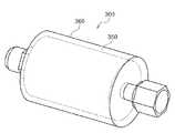
図5を参照すれば、ミストフィルタ300は、ミストフィルタ本体350と、ミストフィルタ本体350を覆って、ミストフィルタ本体350の外側に設けられたヒータ360とを備えている。 Referring to FIG. 5, the
図5、図6を参照すれば、ミストフィルタ300のミストフィルタ本体350は、両端の端部プレート310、340と、端部プレート310、340間に配置された2種類のプレート320、330とを備えている。端部プレート310には継手312が取り付けられている。端部プレート340には継手342が取り付けられている。端部プレート310および継手312内にはガス経路311が形成されている。端部プレート340および継手342内にはガス経路341が形成されている。 Referring to FIGS. 5 and 6, the
2種類のプレート320、330はそれぞれ複数個設けられ、端部プレート310、340間に交互に配置されている。プレート320は平板状のプレート328と、プレート328の外周に設けられた外周部329とを備えている。プレート328の外周付近のみに穴322が設けられている。プレート330は平板状のプレート338と、プレート338の外周に設けられた外周部339とを備えている。プレート338の中心付近のみに穴332が設けられている。そして、このようなプレート320、330を交互に配置することによって、入り組んだ複雑なガス経路370となり、気化不良や再液化で発生した液滴の加熱された壁面(プレート328、338)への衝突確率を高めることができる。なお、穴322、332の大きさは圧力に依存し、好ましくは、直径1〜3mmである。 A plurality of two types of
液体原料291が気化器270(図3参照)で気化して気体状態となった原料ガスおよび気化不良や再液化で生じた液滴は、端部プレート310および継手312内のガス経路311からミストフィルタ本体350内に導入され、1枚目のプレート320の平板状のプレート328の中央部421に衝突し、その後、プレート328の外周付近に設けられた穴322を通過して、2枚目のプレート330の平板状のプレート338の外周部432に衝突し、その後、プレート338の中心付近に設けられた穴332を通過して、3枚目のプレート320の平板状のプレート328の中央部422に衝突し、その後、同様にしてプレート330、320を順次通過して端部プレート340および継手342内のガス経路341を通ってミストフィルタ本体350から導出され、下流のガスフィルタ301(図3参照)に送られる。 The raw material gas in which the liquid
ミストフィルタ本体350は、ヒータ360(図5参照)によって外側から加熱される。ミストフィルタ本体350は、複数のプレート320とプレート330を備え、プレート320は、平板状のプレート328とプレート328の外周に設けられた外周部329とを備え、プレート330は、平板状のプレート338とプレート338の外周に設けられた外周部339とを備えている。プレート328と外周部329は一体的に構成され、プレート338と外周部339は一体的に構成されているので、ヒータ360によってミストフィルタ本体350が外側から加熱されると、熱は効率よく平板状のプレート328、338に伝えられる。 The mist filter
ミストフィルタ本体350では、上述のように、複数のプレート320とプレート330により入り組んだ複雑なガス経路370を構成しているので、ミストフィルタ本体350内での圧力損失を上げすぎずに、気化して気体状態となった原料ガスおよび気化不良や再液化で生じた液滴の、加熱された平板状のプレート328、338への衝突確率を高めることができる。そして、気化不良や再液化で生じた液滴は、十分な熱量をもったミストフィルタ本体350内で、加熱された平板状のプレート328、338に衝突しながら再加熱され、気化される。 In the mist filter
気化器270とガスフィルタ301との間のガス供給配管232aにミストフィルタ300を設けると、気化し難い液体原料や気化流量が多い場合、気化不良で発生した液滴は、十分に熱量をもったミストフィルタ300内でプレート320の壁面とプレート330の壁面に衝突しながら再加熱され、気化する。そして、処理室201直前のガスフィルタ301で、わずかに残った気化不良や気化器270、ミストフィルタ300内部で発生するパーティクルを捕集する。ミストフィルタ300は気化補助の役割を果たし、気化不良で発生する液滴やパーティクルの無い反応ガスを処理室201内に供給でき、良質な成膜等の基板処理が行える。また、ミストフィルタ300は、ガスフィルタ301の補助の役割も果たし、ガスフィルタ301のフィルタ詰まりを抑制できることで、ガスフィルタ301をメンテナンスフリーにできたり、またはガスフィルタ301のフィルタ交換周期を延ばせる。 When the
(コントローラ)
図7を参照すれば、制御部(制御手段)であるコントローラ280は、CPU(Central Processing Unit)280a、RAM(Random Access Memory)280b、記憶装置280c、I/Oポート280dを備えたコンピュータとして構成されている。RAM280b、記憶装置280c、I/Oポート280dは、内部バス280eを介して、CPU280aとデータ交換可能なように構成されている。コントローラ280には、例えばタッチパネル等として構成された入出力装置282が接続されている。(controller)
Referring to FIG. 7, a
記憶装置280cは、例えばフラッシュメモリ、HDD(Hard Disk Drive)等で構成されている。記憶装置280c内には、基板処理装置の動作を制御する制御プログラムや、後述する基板処理の手順や条件などが記載されたプロセスレシピ等が、読み出し可能に格納されている。なお、プロセスレシピは、後述する基板処理工程における各手順をコントローラ280に実行させ、所定の結果を得ることが出来るように組み合わされたものであり、プログラムとして機能する。以下、このプロセスレシピや制御プログラム等を総称して、単にプログラムともいう。なお、本明細書においてプログラムという言葉を用いた場合は、プロセスレシピ単体のみを含む場合、制御プログラム単体のみを含む場合、または、その両方を含む場合がある。また、RAM280bは、CPU280aによって読み出されたプログラムやデータ等が一時的に保持されるメモリ領域(ワークエリア)として構成されている。 The
I/Oポート280dは、上述のマスフローコントローラ235b、235c、235f、235h、235i、295a、295b、295c、バルブ233a、233b、233c、233e、233f、233g、233h、293i、293j、293a、293b、293c、293d、293e、圧力センサ245、APCバルブ231a、真空ポンプ231c、ヒータ207、温度センサ269、回転機構267、ボートエレベータ115、熱交換器271、ヒータ277、オゾナイザ220、圧力計302等に接続されている。 The I /
CPU280aは、記憶装置280cから制御プログラムを読み出して実行すると共に、入出力装置282からの操作コマンドの入力等に応じて記憶装置280cからプロセスレシピを読み出す。そして、CPU280aは、読み出したプロセスレシピの内容に沿うように、マスフローコントローラ235b、235c、235f、235h、235i、295a、295b、295c、バルブ233a、233b、233c、233e、233f、233g、233h、293i、293j、293a、293b、293c、293d、293eによる各種ガスの流量調整動作、液体マスフローコントローラ295cによる液体原料の流量制御、バルブ233a、233b、233c、233e、233f、233g、233h、293i、293j、293a、293b、293c、293d、293eの開閉動作、APCバルブ231aの開閉動作及びAPCバルブ231aによる圧力センサ245に基づく圧力調整動作、温度センサ269に基づくヒータ207の温度調整動作、真空ポンプ231cの起動および停止、回転機構267によるボート217の回転および回転速度調節動作、ボートエレベータ115によるボート217の昇降動作、熱交換器271の温度調整動作、ヒータ277の温度調整動作、圧力計302による圧力測定動作等を制御する。 The
なお、コントローラ280は、専用のコンピュータとして構成されている場合に限らず、汎用のコンピュータとして構成されていてもよい。例えば、上述のプログラムを格納した外部記憶装置(例えば、磁気テープ、フレキシブルディスクやハードディスク等の磁気ディスク、CDやDVD等の光ディスク、MO等の光磁気ディスク、USBメモリやメモリカード等の半導体メモリ)283を用意し、外部記憶装置283を用いて汎用のコンピュータにプログラムをインストールすること等により、本実施形態に係るコントローラ280を構成することができる。なお、コンピュータにプログラムを供給するための手段は、外部記憶装置283を介して供給する場合に限らない。例えば、インターネットや専用回線等の通信手段を用い、外部記憶装置283を介さずにプログラムを供給するようにしてもよい。なお、記憶装置280cや外部記憶装置283は、コンピュータ読み取り可能な記録媒体として構成される。以下、これらを総称して、単に記録媒体ともいう。なお、本明細書において記録媒体という言葉を用いた場合は、記憶装置280c単体のみを含む場合、外部記憶装置283単体のみを含む場合、または、その両方を含む場合がある。 The
次に、上述の基板処理装置の処理炉を用いて半導体装置(半導体デバイス)の製造工程の一工程として、基板上に絶縁膜を成膜するシーケンス例について、図8、図9を参照して説明する。なお、以下の説明において、基板処理装置を構成する各部の動作はコントローラ121により制御される。 Next, referring to FIG. 8 and FIG. 9, a sequence example of forming an insulating film on a substrate as a process of manufacturing a semiconductor device (semiconductor device) using the processing furnace of the substrate processing apparatus described above will be described. explain. In the following description, the operation of each part constituting the substrate processing apparatus is controlled by the controller 121.
まず、複数枚のウエハ200がボート217に装填(ウエハチャージ)されると(図8、ステップS101参照)、図1に示されているように、複数枚のウエハ200を支持したボート217は、ボートエレベータ115によって持ち上げられて処理室201内に搬入(ボートロード)される(図8、ステップS102参照)。この状態で、シールキャップ219はマニホールド209の下端をシールした状態となる。 First, when a plurality of
処理室201内が所望の圧力(真空度)となるように真空ポンプ231cよって真空排気される。この際、処理室201内の圧力は、圧力センサ245で測定され、この測定された圧力に基づきAPCバルブ231aが、フィードバック制御される(圧力調整)(図8、ステップS103参照)。また、処理室201内が所望の温度となるようにヒータ207によって加熱される。この際、処理室201内が所望の温度分布となるように、温度センサ269が検出した温度情報に基づきヒータ207への通電具合がフィードバック制御される(温度調整)(図8、ステップS103参照)。続いて、回転機構267により、ボート217が回転されることで、ウエハ200が回転される。 The
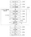
次に、TEMAZガスとO3ガスを処理室201内に供給することにより絶縁膜であるZrO膜を成膜する絶縁膜形成工程(図8、ステップS104参照)を行う。絶縁膜形成工程では次の4つのステップを順次実行する。Next, an insulating film forming step (see FIG. 8, step S104) for forming a ZrO film, which is an insulating film, by supplying TEMAZ gas and O3 gas into the
(絶縁膜形成工程)
<ステップS105>
ステップS105(図8、図9参照、第1の工程)では、まずTEMAZガスを流す。ガス供給管232aのバルブ233aを開き、ベントライン232eのバルブ233eを閉じることで、気化器270、ミストフィルタ300およびガスフィルタ301を介してガス供給管232a内にTEMAZガスを流す。ガス供給管232a内を流れるTEMAZガスは、液体マスフローコントローラ295cにより流量調整される。流量調整されたTEMAZガスはノズル249aのガス供給孔250aから処理室201内に供給されつつガス排気管231から排気される。このとき、同時にバルブ233cを開き、不活性ガス供給管232c内にN2ガス等の不活性ガスを流す。不活性ガス供給管232g内を流れるN2ガスは、マスフローコントローラ235cにより流量調整される。流量調整されたN2ガスはTEMAZガスと一緒に処理室201内に供給されつつガス排気管231から排気される。また、バルブ233hを開いて、ガス供給管232h、ノズル249h、ガス供給孔250hからN2ガス等の不活性ガスを流し、バルブ233iを開いて、ガス供給管232i、ノズル249i、ガス供給孔250iからN2ガス等の不活性ガスを流す。(Insulating film formation process)
<Step S105>
In step S105 (see FIGS. 8 and 9, first step), first, TEMAZ gas is flowed. By opening the
このとき、APCバルブ231aを適正に調整して処理室201内の圧力を、例えば50〜400Paの範囲内の圧力とする。液体マスフローコントローラ295cで制御するTEMAZガスの供給流量は、例えば0.1〜0.5g/分の範囲内の流量とする。TEMAZガスをウエハ200に晒す時間、すなわちガス供給時間(照射時間)は、例えば30〜240秒間の範囲内の時間とする。このときヒータ207の温度は、ウエハ200の温度が、例えば150〜250℃の範囲内の温度となるような温度に設定する。TEMAZガスの供給により、ウエハ200上にジルコニウム含有層が形成される。 At this time, the
<ステップS106>
ステップS106(図8、図9参照、第2の工程)では、バルブ233aを閉じ、バルブ233eを開けて処理室201内へのTEMAZガスの供給を停止し、TEMAZガスをベントライン232eへ流す。このとき、ガス排気管231のAPCバルブ231aは開いたままとして、真空ポンプ231cにより処理室201内を真空排気し、処理室201内に残留する未反応もしくはジルコニウム含有層形成に寄与した後のTEMAZガスを処理室201内から排除する。<Step S106>
In step S106 (see FIGS. 8 and 9, second step), the
なお、このとき、処理室201内に残留するガスを完全に排除しなくてもよく、処理室201内を完全にパージしなくてもよい。処理室201内に残留するガスが微量であれば、その後に行われるステップS107において悪影響が生じることはない。このとき処理室201内に供給するN2ガスの流量も大流量とする必要はなく、例えば、反応管203(処理室201)の容積と同程度の量を供給することで、ステップS107において悪影響が生じない程度のパージを行なうことができる。このように、処理室201内を完全にパージしないことで、パージ時間を短縮し、スループットを向上させることができる。また、N2ガスの消費も必要最小限に抑えることが可能となる。At this time, the gas remaining in the
<ステップS107>
ステップS107(図8、図9参照、第3の工程)では、処理室201内の残留ガスを除去した後、ガス供給管232bのバルブ233j及びバルブ233bを開き、ベントライン232gのバルブ233gを閉めることで、オゾナイザ220によって生成されたO3ガスは、マスフローコントローラ235bにより流量調整され、ノズル249bのガス供給孔250bから処理室201内に供給されつつガス排気管231から排気される。この時同時にバルブ233fを開き、不活性ガス供給管232f内にN2ガスを流す。N2ガスはO3ガスと一緒に処理室201内に供給されつつガス排気管231から排気される。また、バルブ233hを開いて、ガス供給管232h、ノズル249h、ガス供給孔250hからN2ガス等の不活性ガスを流し、バルブ233iを開いて、ガス供給管232i、ノズル249i、ガス供給孔250iからN2ガス等の不活性ガスを流す。<Step S107>
In step S107 (see FIG. 8, FIG. 9, third process), after removing the residual gas in the
O3ガスを流すときは、APCバルブ231aを適正に調整して処理室201内の圧力を、例えば50〜400Paの範囲内の圧力とする。マスフローコントローラ235bで制御するO3ガスの供給流量は、例えば10〜20slmの範囲内の流量とする。O3ガスにウエハ200を晒す時間、すなわちガス供給時間(照射時間)は、例えば60〜300秒間の範囲内の時間とする。このときのヒータ207の温度は、ステップ105と同様、ウエハ200の温度が150〜250℃の範囲内の温度となるような温度に設定する。O3ガスの供給により、ステップS105でウエハ200上に形成されたジルコニウム含有層が酸化されてジルコニウム酸化(ZrO2、以下ZrOとも称する)層が形成される。When flowing the O3 gas, the
<ステップS108>
ステップS108(図8、図9参照、第3の工程)では、ガス供給管232bのバルブ233jを閉じ、バルブ233gを開けて処理室201内へのO3ガスの供給を停止し、O3ガスをベントライン232gへ流す。このとき、ガス排気管231のAPCバルブ31aは開いたままとして、真空ポンプ231gにより処理室201内を真空排気し、処理室201内に残留する未反応もしくは酸化に寄与した後のO3ガスを処理室201内から排除する。<Step S108>
In step S108 (see FIG. 8 and FIG. 9, the third step), the
なお、このとき、処理室201内に残留するガスを完全に排除しなくてもよく、処理室201内を完全にパージしなくてもよい。処理室201内に残留するガスが微量であれば、その後にステップS105を行なう場合であっても悪影響が生じることはない。このとき処理室201内に供給するN2ガスの流量も大流量とする必要はなく、例えば、反応管203(処理室201)の容積と同程度の量を供給することで、次にステップS105を行なう場合であってもステップS105に悪影響が生じない程度のパージを行なうことができる。このように、処理室201内を完全にパージしないことで、パージ時間を短縮し、スループットを向上させることができる。また、N2ガスの消費も必要最小限に抑えることが可能となる。At this time, the gas remaining in the
上述したステップS105〜S108を1サイクルとして、このサイクルを少なくとも1回以上行う(ステップS109)ことにより、ウエハ200上に所定膜厚のジルコニウムおよび酸素を含む絶縁膜、すなわち、ジルコニウム酸化(ZrO2、以下ZrOとも称する)膜を成膜することができる。尚、上述のサイクルは、複数回繰り返すのが好ましい。これにより、ウエハ200上にZrO膜の積層膜が形成される。The above-described steps S105 to S108 are set as one cycle, and this cycle is performed at least once (step S109), whereby an insulating film containing zirconium and oxygen having a predetermined thickness on the
ZrO膜を形成後、ガス供給管232aのバルブ243aを閉じ、ガス供給管232bのバルブ233bを閉じ、不活性ガス供給管232fのバルブ233fを開き、不活性ガス供給管232hのバルブ243hを開き、不活性ガス供給管232iのバルブ243iを開いて、処理室201内にN2ガスを流す。N2ガスはパージガスとして作用し、これにより、処理室201内が不活性ガスでパージされ、処理室201内に残留するガスが処理室201内から除去される(パージ、ステップS110)。その後、処理室201内の雰囲気が不活性ガスに置換され、処理室201内の圧力が常圧に復帰される(大気圧復帰、ステップS111)。After forming the ZrO film, the valve 243a of the
その後、ボートエレベータ115によりシールキャップ219が下降されて、マニホールド209の下端が開口されるとともに、処理済のウエハ200がボート217に保持された状態でマニホールド209の下端からプロセスチューブ205の外部に搬出(ボートアンロード、ステップS112)される。その後、処理済みのウエハ200はボート217より取り出される(ウエハディスチャージ、ステップS113)。 Thereafter, the
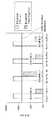
次に、図10を参照して、気化器270に供給する液体原料の流量と、圧力計302(図3参照)で測定した気化器270の出口の圧力との関係を説明する。液体原料としてTEMAZを使用した。液体原料の流量は、液体マスフローコントローラ295c(図3、4参照)によって制御した。TEMAZの気化条件は、気化室274の温度:150℃、不活性ガス供給管232cから供給する希釈用のN2ガス:1slm、不活性ガス供給管292aから上部気化室273に供給するN2キャリアガス:10slm、不活性ガス供給管292bから下部気化室275に供給するN2キャリアガス:15slmとし、TEMAZの流量を5g/minとして気化させた場合と、TEMAZの流量を6g/minとして気化させた場合の結果を図10(A)、図10(B)にそれぞれ示す。Next, the relationship between the flow rate of the liquid raw material supplied to the
図10(A)を参照すれば、TEMAZを5g/minで供給して気化させた場合では、上部気化室273の出口側に接続したガス供給管232a内の圧力波形が、液体原料であるTEMAZの流量波形と同じような、立ち上がり立下りの波形となっている。ここで気化状態の判断基準について説明する。圧力波形の立ち上がり、立下り時の圧力が同じで、液体原料の供給を止めた時点ですぐさま圧力が立ち上がり前の圧力と同じになる場合は、気化良好と判断する。TEMAZを5g/minで供給して気化させた場合の図10(A)では、気化良好であることがわかる。一方で、圧力の立下り時に、立ち上がり前の圧力より高く、さらに立ち上がり前の圧力に戻るまでに時間を要する状態であるとき、これをテーリング(図10(B)のB部参照)と呼んでいる。このテーリングは、液体原料が十分気化されず、残っている液体原料が遅れて気化している現象を示している。この状態は気化不良として判断する。TEMAZを6g/minで供給して気化させた場合の図10(B)では、気化不良であることがわかる。 Referring to FIG. 10A, when TEMAZ is supplied and vaporized at 5 g / min, the pressure waveform in the
図11に、気化条件を変えた場合の気化器270の出口の全圧と分圧の関係について示す。なお、ここで、全圧とは、複数種のガスが混合して成る混合ガスにおいて混合ガス全体としての圧力のことをいい、分圧とは各種ガスそれぞれの圧力のことをいう。全圧は各種ガスの分圧の和に等しい。気化器270の出口の全圧は、不活性ガス供給管232cから供給する希釈用のN2ガスと不活性ガス供給管292aおよび不活性ガス供給管292から供給するN2キャリアガスの総流量が26slmと同じなため、すべて同じ圧力となる。FIG. 11 shows the relationship between the total pressure and the partial pressure at the outlet of the
従来の気化条件であるTEMAZの液体流量:0.3g/min、希釈用のN2ガス流量:25slm、N2キャリアガス流量:1slmでは、TEMAZの150℃の飽和蒸気圧に対して気化余裕が14倍あり、気化良好の範囲である。なお、ここで、気化余裕とはTEMAZの分圧に対するTEMAZの飽和蒸気圧の割合をいう。With the conventional vaporization conditions of TEMAZ liquid flow rate: 0.3 g / min, dilution N2 gas flow rate: 25 slm, N2 carrier gas flow rate: 1 slm, there is a vaporization margin for the TEMAZ saturated vapor pressure of 150 ° C. It is 14 times and is in the range of good vaporization. Here, the vaporization margin means the ratio of the saturated vapor pressure of TEMAZ to the partial pressure of TEMAZ.
TEMAZの液体流量:5g/min、N2キャリアガス流量:25slm、希釈用のN2ガス流量:1slmでの気化余裕も14倍と同じであり、気化良好の範囲である。従って、気化器270の出口のTEMAZ分圧を小さくして、気化余裕を大きくするためには、N2キャリアガス流量を多くすることが有効であることがわかる。The TEMAZ liquid flow rate is 5 g / min, the N2 carrier gas flow rate is 25 slm, the N2 gas flow rate for dilution is 1 slm, and the vaporization margin is 14 times, which is a good vaporization range. Therefore, it can be seen that increasing the N2 carrier gas flow rate is effective for reducing the TEMAZ partial pressure at the outlet of the
一方で、希釈用のN2ガス流量およびN2キャリアガス流量を従来と同じ流量(希釈用のN2ガス流量:25slm、N2キャリアガス流量:1slm)とし、上述のTEMAZの液体流量を5g/minに増加させた場合、気化余裕は1.3倍となり、TEMAZの液体流量:6g/min、N2キャリアガス流量:25slm、希釈用のN2ガス流量:1slmでの気化余裕12倍よりも小さくなるため、気化不良となる。On the other hand, the N2 gas flow rate for dilution and the N2 carrier gas flow rate are the same as the conventional flow rates (N2 gas flow rate for dilution: 25 slm, N2 carrier gas flow rate: 1 slm), and the liquid flow rate of the above TEMAZ is 5 g. When increased to / min, the vaporization margin is 1.3 times, the liquid flow rate of TEMAZ: 6 g / min, the N2 carrier gas flow rate: 25 slm, the N2 gas flow rate for dilution: 12 times the vaporization margin at 1 slm Becomes smaller, resulting in poor vaporization.
以上より、気化室270に流れるN2キャリアガス流量を多くすることで、気化余裕を保ちながら、TEMAZの気化量を増大させることができることがわかる。From the above, it can be seen that by increasing the flow rate of the N2 carrier gas flowing into the vaporizing
また、従来の不活性ガス供給管292aから上部筐体271のガス導入空間279に供給されるN2キャリアガスの最大流量は、1〜2slmと少量である。これは液体原料とキャリアガスの合流部がスリット状の隙間262であり、流量は、隙間262のスリットサイズで決まっているからである。一方、本発明の好ましい実施の形態では、気化室270内の液体原料の分圧を下げるため、隙間262のスリットサイズを大きくし、不活性ガス供給管292aから上部筐体271のガス導入空間279に供給されるN2キャリアガスを多く供給できるようにしている。これにより、TEMAZの液体流量:5g/min、不活性ガス供給管292aおよび不活性ガス供給管292から供給するN2キャリアガス合計:25slmでは、気化余裕が14倍になり、従来のTEMAZの液体供給量(0.3g/min)より約16倍の供給が可能となる。Further, the maximum flow rate of the N2 carrier gas supplied from the conventional inert
図11より、気化器270の出口の全圧が約26600Paであるのに対して、たとえばTEMAZを6g/min、N2キャリアガスを25slm供給した際のTEMAZ分圧は約466Paである。ここから、全圧に対する分圧の割合の上限値は、全圧に対して1.8%以下(約2%以下)が好ましいといえる。なお、TEMAZを5g/min、N2キャリアガスを25slm供給した際の全圧に対するTEMAZ分圧の割合は、約1.5%である。また、下限値としては、マスフローコントローラの最小制御値以上であって、たとえばマスフローコントローラの最小制御値が0.02g/minである場合のTEMAZ分圧1.55Paから、0.006%以上が好ましいといえる。From FIG. 11, the total pressure at the outlet of the
また、気化室274の温度:150℃、N2キャリアガス合計:25slm、希釈用のN2ガス流量:1slmとし、TEMAZの液体流量を0.45g/min、TEMAZの供給時間300secとして、TEMAZとO3の交互供給を75cycle行ってZrO2成膜を行った。成膜後におけるステップカバレージは81%であった。これに対して、気化室274の温度:150℃、N2キャリアガス合計:25slm、希釈用のN2ガス流量:1slmとし、TEMAZの液体流量を3g/min、TEMAZの供給時間60secとして、TEMAZとO3の交互供給を75cycle行ってZrO2成膜を行った。成膜後のステップカバレージが91%になり、ステップカバレージ改善と供給時間の短縮が可能となった。The temperature of the vaporizing
以上のように、本発明の好ましい実施の形態では、蒸気圧が低い液体原料を使用しても、原料液体原料の気化量を多くすると共に、気化室内での気化不良を防止または抑制できる。そして、気化不良に伴う堆積物による異物発生や詰りを抑制または防止できる。また、膜厚均一性を維持することが可能となる。本発明の好ましい実施の形態では、好ましくは、気化室に流れるキャリアガス流量を5slm以上とし、気化室を200Torr以上とすることが好ましい。液体原料の流量は、1g/min以上とすることが好ましい。 As described above, in a preferred embodiment of the present invention, even when a liquid raw material having a low vapor pressure is used, the vaporization amount of the raw material liquid raw material can be increased and the vaporization failure in the vaporization chamber can be prevented or suppressed. And generation | occurrence | production and the clogging of the foreign material by the deposit accompanying a vaporization defect can be suppressed or prevented. In addition, it is possible to maintain film thickness uniformity. In a preferred embodiment of the present invention, it is preferable that the flow rate of the carrier gas flowing into the vaporizing chamber is 5 slm or more and the vaporizing chamber is 200 Torr or more. The flow rate of the liquid raw material is preferably 1 g / min or more.
なお、本発明は、蒸気圧が低い原料を用いる膜種であれば、適用可能である。たとえば、ハフニウム酸化膜(HfO2膜)、アルミニウム酸化膜(Al2O3膜)、チタン酸化膜(TiO膜)、ジルコニウムシリコン酸化膜(ZrSiO膜)、ハフニウムシリコン酸化膜(HfSiO膜)、ジルコニウムアルミニウム酸化膜(ZrAlO膜)、ハフニウムアルミニウム酸化膜(HfAlO膜)、チタン窒化膜(TiN膜)、チタン炭窒化膜(TiCN膜)、タンタル窒化膜(TaN膜)、コバルト膜(Co膜)、ニッケル膜(Ni膜)、ルテニウム膜(Ru膜)、ルテニウム酸化膜(RuO膜)等の成膜に好適に適用される。The present invention is applicable to any film type that uses a raw material having a low vapor pressure. For example, hafnium oxide film (HfO2 film), aluminum oxide film (Al2 O3 film), titanium oxide film (TiO film), zirconium silicon oxide film (ZrSiO film), hafnium silicon oxide film (HfSiO film), zirconium aluminum Oxide film (ZrAlO film), hafnium aluminum oxide film (HfAlO film), titanium nitride film (TiN film), titanium carbonitride film (TiCN film), tantalum nitride film (TaN film), cobalt film (Co film), nickel film (Ni film), ruthenium film (Ru film), ruthenium oxide film (RuO film), etc.
また、本発明は、上記の成膜条件において処理室へ供給される前に配管内で一定量が再液化してしまうような蒸気圧が低い原料であれば、TEMAZ以外のガス種にも適用可能である。たとえば、テトラキスエチルメチルアミノジルコニウム(TEMAZ、Zr[N(CH3)C2H5]4)、テトラキスジエチルアミノジルコニウム(TDEAZ、Zr[N(C2H5)2]4)、テトラキスジメチルアミノジルコニウム(TDMAZ、Zr[N(CH3)2]4)、Zr(MeCp)(NMe2)3、テトラキスエチルメチルアミノハフニウム(TEMAH、Hf[N(CH3)C2H5]4)、テトラキスジエチルアミノハフニウム(TDEAH、Hf[N(C2H5)2]4)、テトラキスジメチルアミノハフニウム(TDMAH、Hf[N(CH3)2]4)、トリメチルアルミニウム(TMA、Al(CH3)3)、四塩化チタン(TiCl4)、トリスジメチルアミノシラン(TDMAS)、塩化タンタル(TaCl)、Nickel Bis[N,N‘ −ditertialbutylacetamidinate](BDTBANi、Ni(tBu2−amd)2、(tBu)NC(CH3)N(tBu)2Ni)、Co amd[(tBu)NC(CH3)N(tBu)2Co]、2,4−ジメチルペンタジエニル)(エチルシクロペンタジエニル)ルテニウム(DER)等が好適に適用できる。In addition, the present invention is applicable to gas types other than TEMAZ as long as the raw material has a low vapor pressure so that a certain amount is reliquefied in the pipe before being supplied to the processing chamber under the above film forming conditions. Is possible. For example, tetrakisethylmethylaminozirconium (TEMAZ, Zr [N (CH3 ) C2 H5 ]4 ), tetrakisdiethylaminozirconium (TDAZ, Zr [N (C2 H5 )2 ]4 ), tetrakisdimethylaminozirconium ( TDMAZ, Zr [N (CH3 )2 ]4 ), Zr (MeCp) (NMe2 )3 , tetrakisethylmethylaminohafnium (TEMAH, Hf [N (CH3 ) C2 H5 ]4 ), tetrakisdiethylaminohafnium (TDEAH, Hf [N (C2 H5 )2 ]4 ), tetrakisdimethylaminohafnium (TDMAH, Hf [N (CH3 )2 ]4 ), trimethylaluminum (TMA, Al (CH3 )3 ), four titanium chloride (TiCl4), tris dimethylamino Shi Down (TDMAS), tantalum chloride (TaCl), Nickel Bis [N , N '-ditertialbutylacetamidinate] (BDTBANi, Ni (tBu 2 -amd) 2, (tBu) NC (CH 3) N (tBu) 2 Ni), Co amd [(tBu) NC (CH3 ) N (tBu)2 Co], 2,4-dimethylpentadienyl) (ethylcyclopentadienyl) ruthenium (DER) and the like can be suitably applied.
また、本発明は、例えば、既存の基板処理装置のプロセスレシピを変更することでも実現できる。プロセスレシピを変更する場合は、本発明に係るプロセスレシピを電気通信回線や当該プロセスレシピを記録した記録媒体を介して既存の基板処理装置にインストールしたり、また、既存の基板処理装置の入出力装置を操作し、そのプロセスレシピ自体を本発明に係るプロセスレシピに変更したりすることも可能である。 The present invention can also be realized by changing a process recipe of an existing substrate processing apparatus, for example. When changing a process recipe, the process recipe according to the present invention is installed in an existing substrate processing apparatus via a telecommunication line or a recording medium recording the process recipe, or input / output of the existing substrate processing apparatus It is also possible to operate the apparatus and change the process recipe itself to the process recipe according to the present invention.
(本発明の好ましい態様)
以下に、本発明の好ましい態様について付記する。(Preferred embodiment of the present invention)
Hereinafter, preferred embodiments of the present invention will be additionally described.
(付記1)
本発明の好ましい一態様によれば、
基板を収容する処理室と、
液体原料を気化する気化器を有し、前記処理室に気化ガスを供給する気化ガス供給系と、
前記気化器に形成される気化室に液体原料およびキャリアガスを供給し、前記気化室内における全圧に対する液体原料の分圧が1.8%以下となるよう前記気化ガス供給系を制御するように構成される制御部と、
を有する基板処理装置が提供される。(Appendix 1)
According to a preferred aspect of the present invention,
A processing chamber for accommodating the substrate;
A vaporizer for vaporizing liquid raw material, and a vaporized gas supply system for supplying vaporized gas to the processing chamber;
A liquid source and a carrier gas are supplied to a vaporization chamber formed in the vaporizer, and the vaporized gas supply system is controlled so that the partial pressure of the liquid source with respect to the total pressure in the vaporization chamber is1.8 % or less. A control unit configured;
A substrate processing apparatus is provided.
(付記2)
付記1の基板処理装置であって、好ましくは、前記制御部は、前記気化室内における全圧に対する液体原料の分圧が0.006%以上となるよう前記気化ガス供給系を制御するように構成される。(Appendix 2)
The substrate processing apparatus according to appendix 1, wherein the control unit is preferably configured to control the vaporized gas supply system so that a partial pressure of the liquid material with respect to the total pressure in the vaporization chamber is0.006 % or more. Is done.
(付記3)
付記1の基板処理装置であって、好ましくは、さらに、前記気化器を加熱する加熱系を有し、前記制御部は、前記液体原料を気化する際は、前記気化器を略150℃で加熱するよう前記加熱系および前記気化ガス供給系を制御するように構成される。(Appendix 3)
The substrate processing apparatus according to appendix 1, preferably further comprising a heating system for heating the vaporizer, wherein the controller heats the vaporizer at about 150 ° C. when vaporizing the liquid material. The heating system and the vaporized gas supply system are configured to control.
(付記4)
付記1の基板処理装置であって、好ましくは、前記処理室に、前記気化ガスと反応する反応ガスを供給する反応ガス供給系をさらに有し、
前記制御部は、前記気化ガスと反応ガスを互いに混合しないよう交互に前記処理室に供給することにより、前記処理室内に収容された基板に膜を形成するよう前記気化ガス供給系、前記反応ガス供給系を制御するように構成される。(Appendix 4)
The substrate processing apparatus according to appendix 1, preferably further comprising a reaction gas supply system for supplying a reaction gas that reacts with the vaporized gas into the processing chamber,
The control unit supplies the vaporized gas and the reaction gas alternately to the process chamber so as not to mix each other, thereby forming the film on the substrate accommodated in the process chamber, the vaporized gas supply system, and the reaction gas. It is configured to control the supply system.
(付記5)
付記1の基板処理装置であって、好ましくは、さらに、前記気化器と前記処理室との間に設けられたガスフィルタと、前記気化器とガスフィルタの間に設けられたミストフィルタを有する。(Appendix 5)
The substrate processing apparatus according to appendix 1, preferably further including a gas filter provided between the vaporizer and the processing chamber, and a mist filter provided between the vaporizer and the gas filter.
(付記6)
付記5の基板処理装置であって、好ましくは、前記ミストフィルタは、異なる位置に穴を有する少なくとも2種のプレートを複数枚組み合わせて構成される。(Appendix 6)
The substrate processing apparatus according to appendix 5, wherein the mist filter is preferably configured by combining a plurality of at least two types of plates having holes at different positions.
(付記7)
本発明の好ましい他の態様によれば、
気化器の気化室内における全圧に対する液体原料の分圧が20%以下となるよう、液体原料とキャリアガスを気化室内に供給し、前記液体原料を気化して気化ガスとする工程と、
前記気化ガスを基板が収容された処理室に供給して、基板を処理する工程と、
を有する半導体装置の製造方法が提供される。(Appendix 7)
According to another preferred aspect of the invention,
Supplying a liquid source and a carrier gas into the vaporization chamber so that the partial pressure of the liquid source with respect to the total pressure in the vaporization chamber of the vaporizer is 20% or less, and vaporizing the liquid source into a vaporized gas;
Supplying the vaporized gas to a processing chamber in which a substrate is accommodated, and processing the substrate;
A method of manufacturing a semiconductor device having the above is provided.
(付記8)
付記7の半導体装置の製造方法であって、好ましくは、前記液体原料は前記処理室に供給される前に一定量が再液化してしまうような蒸気圧が低い液体原料である。(Appendix 8)
The method for manufacturing a semiconductor device according to appendix 7, wherein the liquid material is preferably a liquid material having a low vapor pressure such that a certain amount is reliquefied before being supplied to the processing chamber.
(付記9)
付記7の半導体装置の製造方法であって、好ましくは、前記液体原料は、ジルコニウム含有原料、ハフニウム含有原料、アルミニウム含有原料、チタン含有原料、シリコン含有原料、タンタル含有原料、コバルト含有原料、ニッケル含有原料、ルテニウム含有原料のいずれかから選択される。(Appendix 9)
The method of manufacturing a semiconductor device according to appendix 7, wherein the liquid material is preferably a zirconium-containing material, a hafnium-containing material, an aluminum-containing material, a titanium-containing material, a silicon-containing material, a tantalum-containing material, a cobalt-containing material, or a nickel-containing material. Either a raw material or a ruthenium-containing raw material is selected.
(付記10)
付記7の半導体装置の製造方法であって、好ましくは、前記液体原料を気化して気化ガスとする工程では、気化室内の圧力を200Torr以上とし、1g/min以上の液体原料、5slm以上のキャリアガスを供給する。(Appendix 10)
The method of manufacturing a semiconductor device according to appendix 7, preferably, in the step of vaporizing the liquid raw material to form a vaporized gas, the pressure in the vaporizing chamber is set to 200 Torr or higher, the liquid raw material is 1 g / min or higher, and the carrier is 5 slm or higher. Supply gas.
(付記11)
付記10の半導体装置の製造方法であって、好ましくは、前記液体原料を気化して気化ガスとする工程では、前記気化室内に、5g/min以上の液体原料を供給する。(Appendix 11)
The method for manufacturing a semiconductor device according to
(付記12)
付記11の半導体装置の製造方法であって、好ましくは、前記液体原料を気化して気化ガスとする工程では、前記気化室内に、6g/min以上の液体原料を供給する。(Appendix 12)
The method for manufacturing a semiconductor device according to appendix 11, preferably, in the step of vaporizing the liquid material into a vaporized gas, a liquid material of 6 g / min or more is supplied into the vaporization chamber.
(付記13)
付記10の半導体装置の製造方法であって、好ましくは、前記液体原料を気化して気化ガスとする工程では、前記気化室内に、キャリアガスを25sm以上供給する。(Appendix 13)
The method for manufacturing a semiconductor device according to
(付記14)
付記13の半導体装置の製造方法であって、好ましくは、前記液体原料を気化して気化ガスとする工程では、前記気化器の上部から10slmのキャリアガスを前記気化室内に供給し、前記気化器の下部から15slmのキャリアガスを前記気化室内に供給し、合わせて少なくとも25slmのキャリアガスを前記気化室内に供給する。(Appendix 14)
The manufacturing method of a semiconductor device according to appendix 13, preferably, in the step of vaporizing the liquid raw material to form a vaporized gas, a carrier gas of 10 slm is supplied into the vaporization chamber from above the vaporizer, and the vaporizer A carrier gas of 15 slm is supplied into the vaporization chamber from the lower part of the gas, and a carrier gas of at least 25 slm is supplied into the vaporization chamber.
(付記15)
本発明の好ましい他の態様によれば、
気化器の気化室内における全圧に対する液体原料の分圧が1.8%以下となるよう、液体原料とキャリアガスを気化室内に供給し、前記液体原料を気化して気化ガスとする工程と、
前記気化ガスを基板が収容された処理室に供給して、基板を処理する工程と、
を有する基板処理方法が提供される。(Appendix 15)
According to another preferred aspect of the invention,
Supplying a liquid source and a carrier gas into the vaporization chamber so that a partial pressure of the liquid source with respect to the total pressure in the vaporization chamber of the vaporizer is1.8 % or less, and evaporating the liquid source into a vaporized gas;
Supplying the vaporized gas to a processing chamber in which a substrate is accommodated, and processing the substrate;
A substrate processing method is provided.
(付記16)
本発明の好ましいさらに他の態様によれば、
気化器の気化室内における全圧に対する液体原料の分圧が1.8%以下となるよう、液体原料とキャリアガスを気化器の気化室内に供給し、前記液体原料を気化する気化器と、ガスフィルタと、ミストフィルタを有する気化システムが提供される。(Appendix 16)
According to still another preferred aspect of the present invention,
A vaporizer for supplying the liquid raw material and a carrier gas into the vaporizer chamber of the vaporizer so that the partial pressure of the liquid raw material with respect to the total pressure in the vaporizer chamber is1.8 % or less; A vaporization system having a filter and a mist filter is provided.
(付記17)
本発明の好ましいさらに他の態様によれば、
気化器を加熱する手順と、
前記気化器の気化室内における全圧に対する液体原料の分圧が1.8%以下となるよう、液体原料とキャリアガスを気化室内に供給する手順と、
を行うことで、液体原料を気化する手順をコンピュータに実行させるプログラムが提供される。(Appendix 17)
According to still another preferred aspect of the present invention,
A procedure for heating the vaporizer;
Supplying the liquid source and the carrier gas into the vaporization chamber so that the partial pressure of the liquid source with respect to the total pressure in the vaporization chamber of the vaporizer is1.8 % or less;
By performing the above, a program for causing the computer to execute a procedure for vaporizing the liquid raw material is provided.
(付記18)
本発明の好ましいさらに他の態様によれば、
気化器を加熱する手順と、
前記気化器の気化室内における全圧に対する液体原料の分圧が1.8%以下となるよう、液体原料とキャリアガスを気化室内に供給する手順と、
を行うことで、液体原料を気化する手順をコンピュータに実行させるプログラムを記録したコンピュータ読み取り可能な記録媒体が提供される。(Appendix 18)
According to still another preferred aspect of the present invention,
A procedure for heating the vaporizer;
Supplying the liquid source and the carrier gas into the vaporization chamber so that the partial pressure of the liquid source with respect to the total pressure in the vaporization chamber of the vaporizer is1.8 % or less;
By performing the above, a computer-readable recording medium recording a program for causing a computer to execute a procedure for vaporizing a liquid raw material is provided.
以上、本発明の種々の典型的な実施の形態を説明してきたが、本発明はそれらの実施の形態に限定されない。従って、本発明の範囲は、次の特許請求の範囲によってのみ限定されるものである。 While various typical embodiments of the present invention have been described above, the present invention is not limited to these embodiments. Accordingly, the scope of the invention is limited only by the following claims.
200 ウエハ
201 処理室
202 処理炉
205 プロセスチューブ
220 オゾナイザ
232a、232b ガス供給管
235b、235c、295a、295b マスフローコントローラ
295c 液体マスフローコントローラ
249a、249b ノズル
269 温度センサ
270 気化器
274 気化室
280 コントローラ
291 液体原料
300 ミストフィルタ
301 ガスフィルタ
302 圧力計200
Claims (18)
Translated fromJapanese液体原料を気化する気化器と、前記気化器内に形成された気化室に接続され前記気化室内に前記液体原料を供給する液体原料供給ユニットと、前記液体原料供給ユニットとは独立して前記気化室に接続され前記気化室に前記キャリアガスを供給するキャリアガス供給ユニットと、を有し、前記処理室に気化ガスを供給する気化ガス供給系と、
前記気化ガス供給系を制御して、前記液体原料供給ユニットおよび前記キャリアガス供給ユニットからそれぞれ前記液体原料および前記キャリアガスを前記気化室に供給し、前記キャリアガスの流量が5slm以上、前記気化室内における全圧に対する前記液体原料の分圧が1.8%以下となるよう前記液体原料の流量および前記キャリアガスの流量を調整するように構成される制御部と、
を有する基板処理装置。A processing chamber for accommodating the substrate;
A vaporizer for vaporizing a liquid material,which is connected to the vaporization chambers formed in the vaporizer and the liquid material supply unit for supplying the liquid material intothe vaporizing chamber, independently said vaporized from said liquid material supply unit A carrier gas supply unit connected to a chamber for supplying the carrier gas to the vaporization chamber, and a vaporized gas supply system for supplying a vaporized gas to the processing chamber,
The vaporized gas supply system is controlled to supply the liquid material and the carrier gas from the liquid material supply unit and the carrier gas supply unit to the vaporization chamber, respectively, andthe flow rate of the carrier gas is 5 slm or more, A control unit configured to adjust the flowrate of the liquid source and the flow rate of the carrier gas so that the partial pressure of the liquid source with respect to the total pressure at1.8 % is1.8 % or less;
A substrate processing apparatus.
前記制御部は、前記気化ガスと前記反応ガスを互いに混合しないよう交互に前記処理室に供給することにより、前記処理室内に収容された基板に膜を形成するよう前記気化ガス供給系、前記反応ガス供給系を制御するように構成される請求項1から請求項4のいずれかに記載の基板処理装置。The process chamber further includes a reaction gas supply system that supplies a reaction gas that reacts with the vaporized gas,
The controller supplies the vaporized gas and the reaction gas alternately to the processing chamber so as not to mix each other, thereby forming the film on the substrate accommodated in the processing chamber, the reaction gas supply system, and the reaction the substrate processing apparatus according toclaim4 configured claim 1 so as to control the gas supply system.
前記気化ガスを基板が収容された処理室に供給して、前記基板を処理する工程と、
を有する半導体装置の製造方法。A liquid source and a carrier gas are supplied from an independent liquid source gas supply unit and a carrier gas supply unit to the vaporization chamber of the vaporizer, and the flow rate of the carrier gas is 5 slm or more, and the liquid source with respect to the total pressure in the vaporization chamber Adjusting the flowrate of the liquid raw material and the flow rate of the carrier gas so that the partial pressure is1.8 % or less, evaporating the liquid raw material into a vaporized gas;
Supplying the vaporized gas to a processing chamber in which a substrate is accommodated, and processing the substrate;
A method for manufacturing a semiconductor device comprising:
気化器の気化室内に液体原料とキャリアガスとをそれぞれ独立した液体原料ガス供給ユニットおよびキャリアガス供給ユニットから供給し、前記キャリアガスの流量が5slm以上、前記気化室内における全圧に対する前記液体原料の分圧が1.8%以下となるよう前記液体原料の流量および前記キャリアガスの流量を調整する手順と、
を行うことで、液体原料を気化する手順をコンピュータにより基板処理装置に実行させるプログラム。A procedure for heating the vaporizer;
A liquid source and a carrier gas are supplied from an independent liquid source gas supply unit and a carrier gas supply unit to the vaporization chamber of the vaporizer, and the flow rate of the carrier gas is 5 slm or more, and the liquid source with respect to the total pressure in the vaporization chamber Adjusting the flowrate of the liquid raw material and the flow rate of the carrier gas so that the partial pressure is1.8 % or less;
A program for causing the substrate processing apparatus to execute a procedure for vaporizing the liquid source by a computer.
液体原料を気化する気化器と、前記気化器内に形成された気化室に接続され前記気化室内に前記液体原料を供給する液体原料供給ユニットと、前記液体原料供給ユニットとは独立して前記気化室に接続され前記気化室に前記キャリアガスを供給するキャリアガス供給ユニットと、を有し、前記処理室に気化ガスを供給する気化ガス供給系と、 A vaporizer that vaporizes a liquid material; a liquid material supply unit that is connected to a vaporization chamber formed in the vaporizer and that supplies the liquid material into the vaporization chamber; and the vaporization material is independent of the liquid material supply unit. A carrier gas supply unit connected to a chamber for supplying the carrier gas to the vaporization chamber, and a vaporized gas supply system for supplying a vaporized gas to the processing chamber,
前記気化ガス供給系を制御して、前記液体原料供給ユニットおよび前記キャリアガス供給ユニットからそれぞれ前記液体原料および前記キャリアガスを前記気化室に供給し、前記キャリアガスの流量が5slm以上、前記気化室内における前記液体原料の分圧に対する前記液体原料の飽和蒸気圧の割合が12以上となるよう前記液体原料の流量および前記キャリアガスの流量を調整するように構成される制御部と、 The vaporized gas supply system is controlled to supply the liquid material and the carrier gas from the liquid material supply unit and the carrier gas supply unit to the vaporization chamber, respectively, and the flow rate of the carrier gas is 5 slm or more, A control unit configured to adjust the flow rate of the liquid source and the flow rate of the carrier gas so that the ratio of the saturated vapor pressure of the liquid source to the partial pressure of the liquid source is 12 or more;
を有する基板処理装置。 A substrate processing apparatus.
前記気化ガスを基板が収容された処理室に供給して、前記基板を処理する工程と、 Supplying the vaporized gas to a processing chamber in which a substrate is accommodated, and processing the substrate;
を有する半導体装置の製造方法。 A method for manufacturing a semiconductor device comprising:
気化器の気化室内に液体原料とキャリアガスとをそれぞれ独立した液体原料ガス供給ユニットおよびキャリアガス供給ユニットから供給し、前記キャリアガスの流量が5slm以上、前記気化室内における前記液体原料の分圧に対する前記液体原料の飽和蒸気圧の割合が12以上となるよう前記液体原料の流量および前記キャリアガスの流量を調整する手順と、 A liquid source and a carrier gas are supplied from an independent liquid source gas supply unit and a carrier gas supply unit to the vaporization chamber of the vaporizer, respectively, and the flow rate of the carrier gas is 5 slm or more, with respect to the partial pressure of the liquid source in the vaporization chamber Adjusting the flow rate of the liquid material and the flow rate of the carrier gas so that the saturated vapor pressure ratio of the liquid material is 12 or more;
を行うことで、液体原料を気化する手順をコンピュータにより基板処理装置に実行させるプログラム。 A program for causing the substrate processing apparatus to execute a procedure for vaporizing the liquid source by a computer.
Priority Applications (3)
| Application Number | Priority Date | Filing Date | Title |
|---|---|---|---|
| JP2012286055AJP6078335B2 (en) | 2012-12-27 | 2012-12-27 | Substrate processing apparatus, semiconductor device manufacturing method, vaporization system, vaporizer, and program |
| KR1020130164384AKR101587702B1 (en) | 2012-12-27 | 2013-12-26 | Substrate processing apparatus, method of manufacturing semiconductor device and vaporization system |
| US14/140,837US20140182515A1 (en) | 2012-12-27 | 2013-12-26 | Substrate processing apparatus, method of manufacturing semiconductor device and vaporization system |
Applications Claiming Priority (1)
| Application Number | Priority Date | Filing Date | Title |
|---|---|---|---|
| JP2012286055AJP6078335B2 (en) | 2012-12-27 | 2012-12-27 | Substrate processing apparatus, semiconductor device manufacturing method, vaporization system, vaporizer, and program |
Publications (3)
| Publication Number | Publication Date |
|---|---|
| JP2014127702A JP2014127702A (en) | 2014-07-07 |
| JP2014127702A5 JP2014127702A5 (en) | 2016-06-02 |
| JP6078335B2true JP6078335B2 (en) | 2017-02-08 |
Family
ID=51015703
Family Applications (1)
| Application Number | Title | Priority Date | Filing Date |
|---|---|---|---|
| JP2012286055AActiveJP6078335B2 (en) | 2012-12-27 | 2012-12-27 | Substrate processing apparatus, semiconductor device manufacturing method, vaporization system, vaporizer, and program |
Country Status (3)
| Country | Link |
|---|---|
| US (1) | US20140182515A1 (en) |
| JP (1) | JP6078335B2 (en) |
| KR (1) | KR101587702B1 (en) |
Families Citing this family (19)
| Publication number | Priority date | Publication date | Assignee | Title |
|---|---|---|---|---|
| US9631276B2 (en)* | 2014-11-26 | 2017-04-25 | Lam Research Corporation | Systems and methods enabling low defect processing via controlled separation and delivery of chemicals during atomic layer deposition |
| US9920844B2 (en) | 2014-11-26 | 2018-03-20 | Lam Research Corporation | Valve manifold deadleg elimination via reentrant flow path |
| WO2017009997A1 (en) | 2015-07-16 | 2017-01-19 | 株式会社日立国際電気 | Substrate processing device, semiconductor device production method, and vaporization system |
| TWI624554B (en)* | 2015-08-21 | 2018-05-21 | 弗里松股份有限公司 | Evaporation source |
| MY190445A (en) | 2015-08-21 | 2022-04-21 | Flisom Ag | Homogeneous linear evaporation source |
| JP6448502B2 (en) | 2015-09-09 | 2019-01-09 | 株式会社Kokusai Electric | Semiconductor device manufacturing method, substrate processing apparatus, and program |
| WO2017056244A1 (en)* | 2015-09-30 | 2017-04-06 | 株式会社日立国際電気 | Substrate treatment apparatus, method for manufacturing semiconductor device, and recording medium |
| KR102122786B1 (en)* | 2015-12-18 | 2020-06-26 | 가부시키가이샤 코쿠사이 엘렉트릭 | Storage device, vaporizer, substrate processing device and method for manufacturing semiconductor device |
| KR102248120B1 (en)* | 2016-03-24 | 2021-05-04 | 가부시키가이샤 코쿠사이 엘렉트릭 | Vaporizer, substrate processing apparatus and method of manufacturing semiconductor device |
| KR20180027780A (en)* | 2016-09-07 | 2018-03-15 | 주성엔지니어링(주) | Vaporizer |
| JP6891018B2 (en)* | 2017-03-27 | 2021-06-18 | 株式会社Kokusai Electric | Manufacturing method for substrate processing equipment, vaporization system, mist filter, and semiconductor equipment |
| JP6742265B2 (en)* | 2017-03-28 | 2020-08-19 | 東京エレクトロン株式会社 | Method for suppressing adhesion of cleaning by-product, method for cleaning reaction chamber using the same, and room temperature film forming apparatus |
| JP6602332B2 (en) | 2017-03-28 | 2019-11-06 | 株式会社Kokusai Electric | Semiconductor device manufacturing method, substrate processing apparatus, and program |
| JP6923396B2 (en)* | 2017-08-31 | 2021-08-18 | 株式会社Screenホールディングス | Adhesion strengthening treatment device and adhesion strengthening treatment method |
| US11661654B2 (en) | 2018-04-18 | 2023-05-30 | Lam Research Corporation | Substrate processing systems including gas delivery system with reduced dead legs |
| JP7055075B2 (en)* | 2018-07-20 | 2022-04-15 | 東京エレクトロン株式会社 | Heat treatment equipment and heat treatment method |
| KR20220043028A (en)* | 2020-09-28 | 2022-04-05 | 가부시키가이샤 코쿠사이 엘렉트릭 | Vaporizing system, substrate processing apparatus and method of manufacturing semiconductor device |
| KR102822866B1 (en)* | 2020-12-17 | 2025-06-19 | 주식회사 원익아이피에스 | Filter unit and apparatus for processing substrate |
| WO2022256478A1 (en)* | 2021-06-04 | 2022-12-08 | Inficon, Inc. | A system and method for mass flow measurement and control of process gases in a carrier stream using one or more quartz crystal microbalance sensors |
Family Cites Families (44)
| Publication number | Priority date | Publication date | Assignee | Title |
|---|---|---|---|---|
| DE3585901D1 (en)* | 1984-02-13 | 1992-05-27 | Iii Jerome J Schmitt | METHOD AND DEVICE FOR GAS RAY DEPOSITION OF CONDUCTIVE AND DIELECTRIC THICKEN FILMS AND PRODUCTS MADE THEREOF. |
| US5100868A (en)* | 1990-04-17 | 1992-03-31 | Alfred University Inc. | Process for preparing superconducting films by radio-frequency-generated aerosol plasma deposition |
| JP3391829B2 (en)* | 1991-12-26 | 2003-03-31 | キヤノン株式会社 | Chemical vapor deposition method and apparatus using liquid raw material |
| US5383970A (en)* | 1991-12-26 | 1995-01-24 | Canon Kabushiki Kaisha | Chemical vapor deposition method for forming a deposited film with the use of a liquid raw material and apparatus suitable for practicing said method |
| US5520969A (en)* | 1994-02-04 | 1996-05-28 | Applied Materials, Inc. | Method for in-situ liquid flow rate estimation and verification |
| JP3601153B2 (en)* | 1995-12-27 | 2004-12-15 | 東京エレクトロン株式会社 | Cleaning method for processing gas supply device |
| JP3392299B2 (en)* | 1996-09-18 | 2003-03-31 | 株式会社フジクラ | Raw material solution vaporizer for CVD |
| US6409839B1 (en)* | 1997-06-02 | 2002-06-25 | Msp Corporation | Method and apparatus for vapor generation and film deposition |
| WO1998055668A1 (en)* | 1997-06-02 | 1998-12-10 | Msp Corporation | Method and apparatus for vapor generation and film deposition |
| JPH11111644A (en)* | 1997-09-30 | 1999-04-23 | Japan Pionics Co Ltd | Vaporization supply device |
| US20030101938A1 (en)* | 1998-10-27 | 2003-06-05 | Applied Materials, Inc. | Apparatus for the deposition of high dielectric constant films |
| KR100368319B1 (en)* | 1998-12-30 | 2003-03-17 | 주식회사 하이닉스반도체 | Liquid delivery system |
| WO2002020864A2 (en)* | 2000-06-16 | 2002-03-14 | Applied Materials, Inc. | System and method for depositing high dielectric constant materials and compatible conductive materials |
| US7163197B2 (en)* | 2000-09-26 | 2007-01-16 | Shimadzu Corporation | Liquid substance supply device for vaporizing system, vaporizer, and vaporization performance appraisal method |
| JP4421119B2 (en)* | 2001-01-11 | 2010-02-24 | 株式会社日立国際電気 | Manufacturing method of semiconductor device |
| US6790475B2 (en)* | 2002-04-09 | 2004-09-14 | Wafermasters Inc. | Source gas delivery |
| JP3809391B2 (en)* | 2002-04-19 | 2006-08-16 | 株式会社アルバック | Thin film forming equipment |
| US6772072B2 (en)* | 2002-07-22 | 2004-08-03 | Applied Materials, Inc. | Method and apparatus for monitoring solid precursor delivery |
| US6921062B2 (en)* | 2002-07-23 | 2005-07-26 | Advanced Technology Materials, Inc. | Vaporizer delivery ampoule |
| JP4288049B2 (en)* | 2002-08-07 | 2009-07-01 | 日本パイオニクス株式会社 | Vaporization supply method |
| US6779378B2 (en) | 2002-10-30 | 2004-08-24 | Asm International N.V. | Method of monitoring evaporation rate of source material in a container |
| JP2005039034A (en)* | 2003-07-14 | 2005-02-10 | Japan Pionics Co Ltd | Vaporization supply apparatus and vaporization supply method |
| JP4607474B2 (en)* | 2004-02-12 | 2011-01-05 | 東京エレクトロン株式会社 | Deposition equipment |
| US20060060139A1 (en)* | 2004-04-12 | 2006-03-23 | Mks Instruments, Inc. | Precursor gas delivery with carrier gas mixing |
| US8435351B2 (en)* | 2004-11-29 | 2013-05-07 | Tokyo Electron Limited | Method and system for measuring a flow rate in a solid precursor delivery system |
| US20070042119A1 (en)* | 2005-02-10 | 2007-02-22 | Larry Matthysse | Vaporizer for atomic layer deposition system |
| JP4601535B2 (en)* | 2005-09-09 | 2010-12-22 | 株式会社リンテック | A vaporizer capable of vaporizing liquid raw materials at low temperatures |
| JP4973071B2 (en)* | 2006-08-31 | 2012-07-11 | 東京エレクトロン株式会社 | Deposition equipment |
| US20080145533A1 (en)* | 2006-11-29 | 2008-06-19 | Hitachi Kokusai Electric Inc. | Substrate processing apparatus and substrate processing method |
| US20080141937A1 (en)* | 2006-12-19 | 2008-06-19 | Tokyo Electron Limited | Method and system for controlling a vapor delivery system |
| WO2009034938A1 (en)* | 2007-09-10 | 2009-03-19 | Ulvac, Inc. | Organic-material vapor generator, film deposition source, and film deposition apparatus |
| JP5213341B2 (en)* | 2007-03-20 | 2013-06-19 | 東京エレクトロン株式会社 | Vaporizer, vaporization module, film deposition system |
| JP5104151B2 (en)* | 2007-09-18 | 2012-12-19 | 東京エレクトロン株式会社 | Vaporization apparatus, film forming apparatus, film forming method, and storage medium |
| WO2009038168A1 (en)* | 2007-09-21 | 2009-03-26 | Tokyo Electron Limited | Film forming apparatus and film forming method |
| JP5200551B2 (en)* | 2008-01-18 | 2013-06-05 | 東京エレクトロン株式会社 | Vaporized raw material supply apparatus, film forming apparatus, and vaporized raw material supply method |
| JP5385002B2 (en)* | 2008-06-16 | 2014-01-08 | 株式会社日立国際電気 | Substrate processing apparatus and semiconductor device manufacturing method |
| US8151814B2 (en)* | 2009-01-13 | 2012-04-10 | Asm Japan K.K. | Method for controlling flow and concentration of liquid precursor |
| JP2010219292A (en) | 2009-03-17 | 2010-09-30 | Tokyo Electron Ltd | Film forming method |
| JP2011003599A (en)* | 2009-06-16 | 2011-01-06 | Elpida Memory Inc | Apparatus and method of producing semiconductor |
| JP2011054938A (en)* | 2009-08-07 | 2011-03-17 | Hitachi Kokusai Electric Inc | Substrate processing apparatus, method of manufacturing semiconductor device, and method of confirming operation of liquid flowrate control device |
| JP5610438B2 (en)* | 2010-01-29 | 2014-10-22 | 株式会社日立国際電気 | Substrate processing apparatus and semiconductor device manufacturing method |
| JP5573666B2 (en)* | 2010-12-28 | 2014-08-20 | 東京エレクトロン株式会社 | Raw material supply apparatus and film forming apparatus |
| JP2012162754A (en)* | 2011-02-03 | 2012-08-30 | Ulvac Japan Ltd | Vaporization method and vaporizer of liquid material |
| US9243325B2 (en)* | 2012-07-18 | 2016-01-26 | Rohm And Haas Electronic Materials Llc | Vapor delivery device, methods of manufacture and methods of use thereof |
- 2012
- 2012-12-27JPJP2012286055Apatent/JP6078335B2/enactiveActive
- 2013
- 2013-12-26KRKR1020130164384Apatent/KR101587702B1/enactiveActive
- 2013-12-26USUS14/140,837patent/US20140182515A1/enactivePending
Also Published As
| Publication number | Publication date |
|---|---|
| US20140182515A1 (en) | 2014-07-03 |
| KR101587702B1 (en) | 2016-01-21 |
| JP2014127702A (en) | 2014-07-07 |
| KR20140085354A (en) | 2014-07-07 |
Similar Documents
| Publication | Publication Date | Title |
|---|---|---|
| JP6078335B2 (en) | Substrate processing apparatus, semiconductor device manufacturing method, vaporization system, vaporizer, and program | |
| JP6222833B2 (en) | Substrate processing apparatus, semiconductor device manufacturing method, and program | |
| CN108660437B (en) | Manufacturing method of semiconductor device, recording medium, and substrate processing apparatus | |
| JP6156972B2 (en) | Semiconductor device manufacturing method, substrate processing apparatus, vaporization system, and mist filter | |
| US8937022B2 (en) | Method of manufacturing semiconductor device, substrate processing method and substrate processing apparatus | |
| JP6023854B1 (en) | Semiconductor device manufacturing method, substrate processing apparatus, and program | |
| WO2013054652A1 (en) | Substrate processing apparatus, substrate processing method, semiconductor device fabrication method and memory medium | |
| US10767260B2 (en) | Substrate processing apparatus, vaporization system and mist filter | |
| KR101520844B1 (en) | Method of manufacturing semiconductor device, substrate processing method and apparatus, non-transitory computer readable recording medium, and semiconductor device | |
| KR102204507B1 (en) | Method of manufacturing semiconductor device, substrate processing apparatus and program | |
| US20200411330A1 (en) | Method of manufacturing semiconductor device, substrate processing apparatus, and recording medium | |
| US11873555B2 (en) | Vaporizer, substrate processing apparatus and method of manufacturing semiconductor device | |
| KR20210093337A (en) | Semiconductor device manufacturing method, substrate processing apparatus and recording medium |
Legal Events
| Date | Code | Title | Description |
|---|---|---|---|
| A621 | Written request for application examination | Free format text:JAPANESE INTERMEDIATE CODE: A621 Effective date:20151202 | |
| A521 | Request for written amendment filed | Free format text:JAPANESE INTERMEDIATE CODE: A523 Effective date:20160407 | |
| A977 | Report on retrieval | Free format text:JAPANESE INTERMEDIATE CODE: A971007 Effective date:20160914 | |
| A131 | Notification of reasons for refusal | Free format text:JAPANESE INTERMEDIATE CODE: A131 Effective date:20160920 | |
| A521 | Request for written amendment filed | Free format text:JAPANESE INTERMEDIATE CODE: A523 Effective date:20161121 | |
| TRDD | Decision of grant or rejection written | ||
| A01 | Written decision to grant a patent or to grant a registration (utility model) | Free format text:JAPANESE INTERMEDIATE CODE: A01 Effective date:20161220 | |
| A61 | First payment of annual fees (during grant procedure) | Free format text:JAPANESE INTERMEDIATE CODE: A61 Effective date:20170116 | |
| R150 | Certificate of patent or registration of utility model | Ref document number:6078335 Country of ref document:JP Free format text:JAPANESE INTERMEDIATE CODE: R150 | |
| S111 | Request for change of ownership or part of ownership | Free format text:JAPANESE INTERMEDIATE CODE: R313111 | |
| R350 | Written notification of registration of transfer | Free format text:JAPANESE INTERMEDIATE CODE: R350 | |
| R250 | Receipt of annual fees | Free format text:JAPANESE INTERMEDIATE CODE: R250 | |
| R250 | Receipt of annual fees | Free format text:JAPANESE INTERMEDIATE CODE: R250 | |
| R250 | Receipt of annual fees | Free format text:JAPANESE INTERMEDIATE CODE: R250 | |
| R250 | Receipt of annual fees | Free format text:JAPANESE INTERMEDIATE CODE: R250 | |
| R250 | Receipt of annual fees | Free format text:JAPANESE INTERMEDIATE CODE: R250 | |
| R250 | Receipt of annual fees | Free format text:JAPANESE INTERMEDIATE CODE: R250 |