JP6076139B2 - Medical light source device - Google Patents
Medical light source deviceDownload PDFInfo
- Publication number
- JP6076139B2 JP6076139B2JP2013041657AJP2013041657AJP6076139B2JP 6076139 B2JP6076139 B2JP 6076139B2JP 2013041657 AJP2013041657 AJP 2013041657AJP 2013041657 AJP2013041657 AJP 2013041657AJP 6076139 B2JP6076139 B2JP 6076139B2
- Authority
- JP
- Japan
- Prior art keywords
- light source
- body cavity
- unit
- ophthalmic observation
- lamp
- Prior art date
- Legal status (The legal status is an assumption and is not a legal conclusion. Google has not performed a legal analysis and makes no representation as to the accuracy of the status listed.)
- Expired - Fee Related
Links
Images

Classifications
- A—HUMAN NECESSITIES
- A61—MEDICAL OR VETERINARY SCIENCE; HYGIENE
- A61B—DIAGNOSIS; SURGERY; IDENTIFICATION
- A61B1/00—Instruments for performing medical examinations of the interior of cavities or tubes of the body by visual or photographical inspection, e.g. endoscopes; Illuminating arrangements therefor
- A61B1/06—Instruments for performing medical examinations of the interior of cavities or tubes of the body by visual or photographical inspection, e.g. endoscopes; Illuminating arrangements therefor with illuminating arrangements
- A61B1/0661—Endoscope light sources
- A—HUMAN NECESSITIES
- A61—MEDICAL OR VETERINARY SCIENCE; HYGIENE
- A61B—DIAGNOSIS; SURGERY; IDENTIFICATION
- A61B1/00—Instruments for performing medical examinations of the interior of cavities or tubes of the body by visual or photographical inspection, e.g. endoscopes; Illuminating arrangements therefor
- A61B1/06—Instruments for performing medical examinations of the interior of cavities or tubes of the body by visual or photographical inspection, e.g. endoscopes; Illuminating arrangements therefor with illuminating arrangements
- A61B1/0655—Control therefor
- A—HUMAN NECESSITIES
- A61—MEDICAL OR VETERINARY SCIENCE; HYGIENE
- A61B—DIAGNOSIS; SURGERY; IDENTIFICATION
- A61B1/00—Instruments for performing medical examinations of the interior of cavities or tubes of the body by visual or photographical inspection, e.g. endoscopes; Illuminating arrangements therefor
- A61B1/00002—Operational features of endoscopes
- A61B1/00059—Operational features of endoscopes provided with identification means for the endoscope
- A—HUMAN NECESSITIES
- A61—MEDICAL OR VETERINARY SCIENCE; HYGIENE
- A61B—DIAGNOSIS; SURGERY; IDENTIFICATION
- A61B1/00—Instruments for performing medical examinations of the interior of cavities or tubes of the body by visual or photographical inspection, e.g. endoscopes; Illuminating arrangements therefor
- A61B1/00112—Connection or coupling means
- A61B1/00121—Connectors, fasteners and adapters, e.g. on the endoscope handle
- A61B1/00124—Connectors, fasteners and adapters, e.g. on the endoscope handle electrical, e.g. electrical plug-and-socket connection
- A—HUMAN NECESSITIES
- A61—MEDICAL OR VETERINARY SCIENCE; HYGIENE
- A61B—DIAGNOSIS; SURGERY; IDENTIFICATION
- A61B1/00—Instruments for performing medical examinations of the interior of cavities or tubes of the body by visual or photographical inspection, e.g. endoscopes; Illuminating arrangements therefor
- A61B1/00112—Connection or coupling means
- A61B1/00121—Connectors, fasteners and adapters, e.g. on the endoscope handle
- A61B1/00126—Connectors, fasteners and adapters, e.g. on the endoscope handle optical, e.g. for light supply cables
- A—HUMAN NECESSITIES
- A61—MEDICAL OR VETERINARY SCIENCE; HYGIENE
- A61B—DIAGNOSIS; SURGERY; IDENTIFICATION
- A61B1/00—Instruments for performing medical examinations of the interior of cavities or tubes of the body by visual or photographical inspection, e.g. endoscopes; Illuminating arrangements therefor
- A61B1/06—Instruments for performing medical examinations of the interior of cavities or tubes of the body by visual or photographical inspection, e.g. endoscopes; Illuminating arrangements therefor with illuminating arrangements
- A61B1/0646—Instruments for performing medical examinations of the interior of cavities or tubes of the body by visual or photographical inspection, e.g. endoscopes; Illuminating arrangements therefor with illuminating arrangements with illumination filters
- A—HUMAN NECESSITIES
- A61—MEDICAL OR VETERINARY SCIENCE; HYGIENE
- A61B—DIAGNOSIS; SURGERY; IDENTIFICATION
- A61B1/00—Instruments for performing medical examinations of the interior of cavities or tubes of the body by visual or photographical inspection, e.g. endoscopes; Illuminating arrangements therefor
- A61B1/06—Instruments for performing medical examinations of the interior of cavities or tubes of the body by visual or photographical inspection, e.g. endoscopes; Illuminating arrangements therefor with illuminating arrangements
- A61B1/0661—Endoscope light sources
- A61B1/0669—Endoscope light sources at proximal end of an endoscope
- A—HUMAN NECESSITIES
- A61—MEDICAL OR VETERINARY SCIENCE; HYGIENE
- A61B—DIAGNOSIS; SURGERY; IDENTIFICATION
- A61B90/00—Instruments, implements or accessories specially adapted for surgery or diagnosis and not covered by any of the groups A61B1/00 - A61B50/00, e.g. for luxation treatment or for protecting wound edges
- A61B90/30—Devices for illuminating a surgical field, the devices having an interrelation with other surgical devices or with a surgical procedure
- A—HUMAN NECESSITIES
- A61—MEDICAL OR VETERINARY SCIENCE; HYGIENE
- A61B—DIAGNOSIS; SURGERY; IDENTIFICATION
- A61B17/00—Surgical instruments, devices or methods
- A61B2017/00477—Coupling
- A61B2017/00482—Coupling with a code
Landscapes
- Health & Medical Sciences (AREA)
- Life Sciences & Earth Sciences (AREA)
- Surgery (AREA)
- General Health & Medical Sciences (AREA)
- Public Health (AREA)
- Veterinary Medicine (AREA)
- Pathology (AREA)
- Nuclear Medicine, Radiotherapy & Molecular Imaging (AREA)
- Animal Behavior & Ethology (AREA)
- Engineering & Computer Science (AREA)
- Biomedical Technology (AREA)
- Heart & Thoracic Surgery (AREA)
- Medical Informatics (AREA)
- Molecular Biology (AREA)
- Biophysics (AREA)
- Physics & Mathematics (AREA)
- Radiology & Medical Imaging (AREA)
- Optics & Photonics (AREA)
- Oral & Maxillofacial Surgery (AREA)
- Endoscopes (AREA)
- Instruments For Viewing The Inside Of Hollow Bodies (AREA)
Description
Translated fromJapanese本発明は、体腔用内視鏡と眼科用観察装置とで共通して使用可能な医療用光源装置に関する。 The present invention relates to a medical light source device that can be used in common by an endoscope for body cavity and an ophthalmic observation apparatus.
体腔用内視鏡は、被検者の体腔(例えば消化管)内に照明光を照射して、病変部の有無やその状態を観察するものである。眼科用観察装置は、被検者の前眼部に照明光を照射して、眼底の血管、網膜及び視神経などの状態を観察することで、緑内障、網膜剥離及び眼底出血などの目の病気を調べるものである。従来、体腔用内視鏡に照明光を供給するための光源装置と、眼科用観察装置に照明光を供給するための光源装置とは、別個の専用品として準備されていた。 The body cavity endoscope is for irradiating illumination light into a body cavity (for example, digestive tract) of a subject to observe the presence or absence of a lesioned part and its state. An ophthalmic observation device irradiates the anterior eye part of a subject with illumination light and observes conditions such as blood vessels, retina and optic nerve in the fundus, thereby preventing eye diseases such as glaucoma, retinal detachment and fundus bleeding. It is something to check. Conventionally, a light source device for supplying illumination light to a body cavity endoscope and a light source device for supplying illumination light to an ophthalmic observation device have been prepared as separate dedicated products.
従来装置(システム)において、このように体腔用内視鏡と眼科用観察装置に別個の光源装置を準備する理由は、体腔用内視鏡が必要とする照明光の光量(光度)と、眼科用観察装置が必要とする照明光の光量(光度)とが大きく異なることに由来する。つまり、照明光の光量が大きい体腔用内視鏡の光源装置に、誤って小光量で足りる眼科用観察装置を接続すると、水晶体で照明光が強く反射して観察できず、また被検者の眼を痛めるおそれがある。このため、従来、体腔用内視鏡の光源装置には眼科用観察装置を接続できないように両者の接続部に互換性を与えないのが技術常識であった。しかし、体腔用内視鏡と眼科用観察装置とで光源装置(光源ランプ)を共用化できれば、電源管理、設備投資の両面で利便性が増大する。 In the conventional device (system), the reason for preparing separate light source devices for the body cavity endoscope and the ophthalmic observation device in this way is that the amount of light (luminous intensity) of illumination light required by the body cavity endoscope and the ophthalmology This is because the light amount (luminous intensity) of the illumination light required by the observation apparatus for use is greatly different. In other words, if an ophthalmic observation device that requires a small amount of light is mistakenly connected to a light source device for a body cavity endoscope with a large amount of illumination light, the illumination light is strongly reflected by the crystalline lens and cannot be observed. May hurt eyes. For this reason, conventionally, it has been common technical knowledge that the connection portion between the two is not provided so that the ophthalmic observation device cannot be connected to the light source device of the endoscope for body cavity. However, if the light source device (light source lamp) can be shared between the endoscope for body cavity and the ophthalmic observation device, convenience in both power management and capital investment increases.
本発明は、以上の着眼に基づいて完成されたものであり、体腔用内視鏡と眼科用観察装置のそれぞれに接続可能であり、体腔用内視鏡と眼科用観察装置のいずれが接続されたかを検出して最適な照明光の光量(光度)を設定し、特に眼科用観察装置の使用時に被検者の眼を痛めることなく良好な観察を行うことができる医療用光源装置を得ることを目的とする。 The present invention has been completed on the basis of the above attention, and can be connected to each of the endoscope for the body cavity and the ophthalmic observation apparatus, and any of the endoscope for the body cavity and the ophthalmic observation apparatus is connected. To obtain a medical light source device capable of detecting the height of light and setting an optimal amount of light (luminous intensity) of illumination light and capable of performing good observation without damaging the eye of the subject, particularly when the ophthalmic observation device is used With the goal.
本発明の医療用光源装置は、被検者の体腔内に照明光を照射する体腔用内視鏡と、被検者の前眼部に照明光を照射する眼科用観察装置とのいずれかを選択的に接続可能な接続部;前記接続部に接続された前記体腔用内視鏡または前記眼科用観察装置に照明光を供給する光源ランプ;前記接続部に前記体腔用内視鏡と前記眼科用観察装置とのいずれが接続されているかを判定する判定部;及び前記判定部が前記接続部に前記体腔用内視鏡が接続されていると判定したときは、前記光源ランプが前記体腔用内視鏡に供給する照明光の最大光量を第1の閾値に設定し、前記判定部が前記接続部に前記眼科用観察装置が接続されていると判定したときは、前記光源ランプが前記眼科用観察装置に供給する照明光の最大光量を前記第1の閾値よりも小さい第2の閾値に設定するランプ制御部;を備えることを特徴としている。 The medical light source device of the present invention includes either a body cavity endoscope that irradiates illumination light into the body cavity of a subject or an ophthalmic observation device that irradiates illumination light to the anterior eye portion of the subject. A connection part that can be selectively connected; a light source lamp that supplies illumination light to the endoscope for body cavity or the ophthalmic observation device connected to the connection part; the endoscope for body cavity and the ophthalmologist to the connection part; A determination unit that determines which of the observation devices is connected; and when the determination unit determines that the body cavity endoscope is connected to the connection unit, the light source lamp is used for the body cavity When the maximum light amount of illumination light supplied to the endoscope is set to a first threshold value and the determination unit determines that the ophthalmic observation device is connected to the connection unit, the light source lamp is the ophthalmic The maximum amount of illumination light supplied to the observation device is smaller than the first threshold value It is characterized in that it comprises a; lamp control unit that sets the second threshold value.
本明細書で「体腔用内視鏡または眼科用観察装置が接続部に接続されている」とは、体腔用内視鏡または眼科用観察装置が、光源ランプからの照明光の供給を受けてこれを照射可能な状態で、接続部に接続されていることを意味する。 In this specification, “the body cavity endoscope or ophthalmic observation apparatus is connected to the connection portion” means that the body cavity endoscope or ophthalmic observation apparatus is supplied with illumination light from the light source lamp. It means that it is connected to the connecting portion in a state where it can be irradiated.
前記ランプ制御部は、前記光源ランプが前記眼科用観察装置に照明光を供給する場合において、前記光源ランプが所定時間連続して点灯したときに、前記光源ランプの点灯を強制終了させることが好ましい。 In the case where the light source lamp supplies illumination light to the ophthalmic observation apparatus, the lamp control unit preferably forcibly ends the lighting of the light source lamp when the light source lamp is continuously lit for a predetermined time. .
本発明の医療用光源装置は、前記接続部に接続された前記体腔用内視鏡または前記眼科用観察装置と通信する通信部をさらに有し、前記判定部は、前記通信部の通信結果に基づいて、前記接続部に前記体腔用内視鏡と前記眼科用観察装置とのいずれが接続されているかを判定することができる。 The medical light source device of the present invention further includes a communication unit that communicates with the endoscope for body cavity or the observation device for ophthalmologic connected to the connection unit, and the determination unit determines the communication result of the communication unit. Based on this, it is possible to determine which of the body cavity endoscope and the ophthalmic observation apparatus is connected to the connection portion.
本発明によれば、体腔用内視鏡と眼科用観察装置のそれぞれに接続可能であり、体腔用内視鏡と眼科用観察装置のいずれが接続されたかを検出して最適な照明光の光量(光度)を設定し、特に眼科用観察装置の使用時に被検者の眼を痛めることなく良好な観察を行うことができる医療用光源装置が得られる。 According to the present invention, it is connectable to the body cavity endoscope and the ophthalmic observation apparatus, and detects which of the body cavity endoscope and the ophthalmic observation apparatus is connected to thereby optimize the amount of illumination light. A light source device for medical use can be obtained in which (luminance) is set and good observation can be performed without damaging the eye of the subject, particularly when the ophthalmic observation device is used.
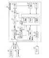
図1、図2を参照して、本発明による医療用光源装置(プロセッサ)100の構成について説明する。 The configuration of a medical light source device (processor) 100 according to the present invention will be described with reference to FIGS.
医療用光源装置100は、該医療用光源装置100の全構成要素の駆動電力源であるAC電源101と、AC電源101の駆動電力をランプ系統に供給するランプ電源102と、AC電源101の駆動電力をシステム系統に供給するシステム電源103とを備えている。 The medical
医療用光源装置100は、ランプ電源102から供給された駆動電力によって照明光を発する光源ランプ110を備えている。光源ランプ110は、ハロゲンランプ、キセノンランプまたはLED等からなる。光源ランプ110は、自身が発する照明光の光量(光度)を可変できるように構成されている。 The medical
医療用光源装置100は、光源ランプ110が発した照明光の光量を調整する回転絞り板(回転チョッパ)111と、回転絞り板111を回転駆動する絞り板駆動モータ112と、回転絞り板111の回転位置を検出する絞り位置検出センサ113とを備えている。 The medical
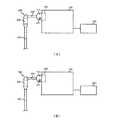
医療用光源装置100は、導光路を有するコネクタ嵌込部(接続部)120を備えており、このコネクタ嵌込部120に、体腔用内視鏡200と眼科用観察装置300とのいずれかが選択的に接続可能となっている。すなわち、図2(A)、(B)に示すように、体腔用内視鏡200と眼科用観察装置300は同一仕様のコネクタ部(接続部)210とコネクタ部(接続部)310を備えており、このコネクタ部210とコネクタ部310が単一のコネクタ嵌込部120に着脱自在となっている(両コネクタ部に互換性を持たせている)。また、コネクタ部210とコネクタ部310には、装置IDを記録したIDメモリ211とIDメモリ311が内蔵されている。医療光源装置100には通信部130が設けられており、この通信部130がIDメモリ211またはIDメモリ311と通信して装置IDを受け取ることで、医療用光源装置100(コネクタ嵌込部120)に接続されているのが体腔用内視鏡200(コネクタ部210)と眼科用観察装置300(コネクタ部310)のいずれであるのかを知ることができるようになっている。 The medical
ここで、IDメモリ211とIDメモリ311が記録した装置IDとしては、例えば、体腔用内視鏡200と眼科用観察装置300の挿入部の長さ情報、体腔用内視鏡200と眼科用観察装置300を使用する医師情報などが挙げられる。 Here, as the device IDs recorded by the
医療用光源装置100に体腔用内視鏡200が接続されているとき(図2(A))は、光源ランプ110が発した照明光は、回転絞り板111とコネクタ嵌込部120の導光路を介して、体腔用内視鏡200のユニバーサルケーブル220から操作部230そして挿入部240の先端部まで延びるライトガイドファイバ(図示せず)内に入射し、このライトガイドファイバの先端部に設けられた照明レンズ(図示せず)から射出される。この照明光は被検者の体腔(例えば消化管)内を照射し、その反射光が挿入部240の先端部に設けられた撮像素子(図示せず)で撮像されて撮像信号となる。この撮像信号は、体腔用内視鏡200の挿入部240から操作部230そしてユニバーサルケーブル220内に配設された画像信号用ケーブル(図示せず)を介して伝送される。 When the
医療用光源装置100に眼科用観察装置300が接続されているとき(図2(B))は、光源ランプ110が発した照明光は、回転絞り板111とコネクタ嵌込部120の導光路を介して、眼科用観察装置300のユニバーサルケーブル320から操作部330そして挿入部340の先端部まで延びるライトガイドファイバ(図示せず)内に入射し、このライトガイドファイバの先端部に設けられた照明レンズ(図示せず)から射出される。この照明光は被検者の前眼部を照射し、その反射光が挿入部340の先端部に設けられた撮像素子(図示せず)で撮像されて撮像信号となる。この撮像信号は、眼科用観察装置300の挿入部340から操作部330そしてユニバーサルケーブル320内に配設された画像信号用ケーブル(図示せず)を介して伝送される。 When the
医療用光源装置100は、体腔用内視鏡200または眼科用観察装置300の画像信号用ケーブルから伝送された撮像信号に画像処理を施す画像処理部140を備えており、画像処理部140が画像処理を施した観察画像は、医療用光源装置100の外部のモニタ400に表示される。 The medical
医療用光源装置100は、該医療用光源装置100の動作全般を制御する制御回路150を備えている。この制御回路150は、絞り板制御部151と、判定部152と、ランプ制御部153とからなる。 The medical
絞り板制御部151は、絞り位置検出センサ113が検出した回転絞り板111の回転位置に基づいて、絞り板駆動モータ112を介して、回転絞り板111を回転駆動制御する。 The diaphragm
判定部152は、通信部130の通信結果に基づいて、医療用光源装置100(コネクタ嵌込部120)に体腔用内視鏡200(コネクタ部210)と眼科用観察装置300(コネクタ部310)のいずれが接続されているかを判定する。 Based on the communication result of the
ランプ制御部153は、判定部152の判定結果に基づいて、光源ランプ110が体腔用内視鏡200または眼科用観察装置300に供給する照明光の最大光量(最大光度)を設定する。
すなわち、ランプ制御部153は、判定部152が医療用光源装置100(コネクタ嵌込部120)に体腔用内視鏡200(コネクタ部210)が接続されていると判定したときは、光源ランプ110が体腔用内視鏡200に供給する照明光の最大光量(最大光度)を「第1の閾値」に設定する。この「第1の閾値」は、例えば、光源ランプ110が能力的に供給可能な最大限度の照明光の光量(光度)である。
一方、ランプ制御部153は、判定部152が医療用光源装置100(コネクタ嵌込部120)に眼科用観察装置300(コネクタ部310)が接続されていると判定したときは、光源ランプ110が眼科用観察装置300に供給する照明光の最大光量(最大光度)を、「第1の閾値」よりも小さい「第2の閾値」に設定する。
本実施形態では、「第1の閾値」を800cd(カンデラ)に設定し、「第2の閾値」を1cd(カンデラ)に設定している。The
That is, the
On the other hand, when the
In the present embodiment, the “first threshold value” is set to 800 cd (candela), and the “second threshold value” is set to 1 cd (candela).
ランプ制御部153は、光源ランプ110が眼科用観察装置300に照明光を供給する場合において、光源ランプ110が所定時間連続して点灯したときに、光源ランプ110の点灯を強制終了させる。すなわち、ランプ制御部153は、光源ランプ110が眼科用観察装置300に照明光の供給を開始すると同時に、タイマー部160による計時を開始させ、光源ランプ110の連続点灯時間が所定時間(例えば5分)に到達した時点で、光源ランプ110の点灯を強制終了させる。 When the
なお、ランプ制御部153は、判定部152が医療用光源装置100(コネクタ嵌込部120)に体腔用内視鏡200(コネクタ部210)が接続されていると判定したときは、光源ランプ110を連続点灯と点滅点灯のいずれかに切り替えて使用できるように点灯制御する。光源ランプ110の連続点灯と点滅点灯の切り替えは、図示しない手動スイッチの入力操作によって実行することができる。
一方、ランプ制御部153は、判定部152が医療用光源装置100(コネクタ嵌込部120)に眼科用観察装置300(コネクタ部310)が接続されていると判定したときは、光源ランプ110を常時連続点灯させて使用するように点灯制御する。ランプ制御部153は、仮に、眼科用観察装置300の接続時において、図示しない手動スイッチによって光源ランプ110を連続点灯から点滅点灯に切り替える旨の入力操作が実行されたときは、モニタ400に「注意!眼科用観察装置の使用時にもかかわらず点滅点灯に切り換えますが本当によろしいですか?」といった警告表示を出して、ユーザの再確認を求め、ユーザの再確認を得られたときにだけ、例外的に、光源ランプ110の点滅点灯を許可する。The
On the other hand, when the
続いて、図3のフローチャートを参照して、以上のように構成された医療用光源装置100の動作について説明する。 Next, the operation of the medical
医療用光源装置100の電源がオンされると、絞り板制御部151が、絞り板駆動モータ112を介して、回転絞り板111の回転位置を初期化する(ステップS1)。 When the power source of the medical
次いで、通信部130が、コネクタ嵌込部120に通信可能なコネクタ部が装着されているか否かを判定する(ステップS2)。通信部130は、コネクタ嵌込部120に通信可能なコネクタ部が装着されていないときは(ステップS2:NO)、何らの処理も行わない。通信部130は、コネクタ嵌込部120に通信可能なコネクタ部が装着されているときは(ステップS2:YES)、装着されたコネクタ部からの装置IDを受信する(ステップS3)。 Next, the
次いで、判定部152が、通信部130の通信結果に基づいて、医療用光源装置100(コネクタ嵌込部120)に体腔用内視鏡200(コネクタ部210)が接続されているか否かを判定する(ステップS4)。判定部152が医療用光源装置100(コネクタ嵌込部120)に体腔用内視鏡200(コネクタ部210)が接続されていると判定したときは(ステップS4:YES)、ランプ制御部153が、光源ランプ110が体腔用内視鏡200に供給する照明光の最大光量(最大光度)を「第1の閾値」に設定した上で(ステップS5)、被検者の体腔内(例えば消化管)を観察する(ステップS6)。 Next, the
判定部152は、医療用光源装置100(コネクタ嵌込部120)に体腔用内視鏡200(コネクタ部210)が接続されていないと判定したときは(ステップS4:NO)、さらに、医療用光源装置100(コネクタ嵌込部120)に眼科用観察装置300(コネクタ部310)が接続されているか否かを判定する(ステップS7)。判定部152が医療用光源装置100(コネクタ嵌込部120)に眼科用観察装置300(コネクタ部310)が接続されていると判定したときは(ステップS7:YES)、ランプ制御部153が、光源ランプ110が眼科用観察装置300に供給する照明光の最大光量(最大光度)を「第1の閾値」よりも小さい「第2の閾値」に設定し(ステップS8)、且つ、タイマー部160による計時を開始させた上で(ステップS9)、被検者の前眼部を観察する(ステップS10)。 When the
ランプ制御部153は、タイマー部160を参照して、光源ランプ110の連続点灯時間が所定時間(例えば5分)に到達するまでは、光源ランプ110の点灯を継続して被検者の前眼部の観察を可能とし(ステップS11:NO、ステップS10)、光源ランプ110の連続点灯時間が所定時間(例えば5分)に到達した時点で、光源ランプ110の点灯を強制終了させて被検者の前眼部の観察を不能にする(ステップS11:YES、ステップS12)。 The
判定部152が医療用光源装置100(コネクタ嵌込部120)に眼科用観察装置300(コネクタ部310)が接続されていないと判定したときは(ステップS7:NO)、医療用光源装置100では使用できない(互換性のない)内視鏡または装置が接続されていることを意味しているので、モニタ400にその旨の警告表示を出す(ステップS13)。 When the
このように本実施形態の医療用光源装置100によれば、ランプ制御部153が、判定部152がコネクタ嵌込部(接続部)120に体腔用内視鏡200が接続されていると判定したときは、光源ランプ110が体腔用内視鏡200に供給する照明光の最大光量(最大光度)を「第1の閾値」に設定し、判定部152がコネクタ嵌込部(接続部)120に眼科用観察装置300が接続されていると判定したときは、光源ランプ110が眼科用観察装置300に供給する照明光の最大光量(最大光度)を「第1の閾値」よりも小さい「第2の閾値」に設定する。これにより、体腔用内視鏡200と眼科用観察装置300のそれぞれに対して最適な照明光の光量(光度)を設定し、特に眼科用観察装置300の使用時に被検者の眼を痛めることなく良好な観察を行うことができる。 Thus, according to the medical
また、ランプ制御部153が、光源ランプ110が眼科用観察装置300に照明光を供給する場合において、光源ランプ110が所定時間連続して点灯したときに、光源ランプ110の点灯を強制終了させるので、光源ランプ110の不用意な連続点灯によって被検者の眼を痛めることなく良好な観察を行うことができる。 In addition, when the
以上の実施形態では、「第1の閾値」を800cd(カンデラ)に設定し、「第2の閾値」を1cd(カンデラ)に設定した場合を例示して説明している。しかし、これらはあくまで一例であって、「第1の閾値」と「第2の閾値」の具体的数値は種々の設計変更が可能である。 In the above embodiment, the case where the “first threshold value” is set to 800 cd (candela) and the “second threshold value” is set to 1 cd (candela) is described as an example. However, these are merely examples, and the specific numerical values of the “first threshold” and the “second threshold” can be variously changed.
以上の実施形態では、ランプ制御部153が、光源ランプ110の連続点灯時間が5分に到達した時点で光源ランプ110の点灯を強制終了させる場合を例示して説明している。しかし、光源ランプ110の連続点灯時間(点灯を強制終了させるまでの時間)は5分に限定されず種々の設計変更が可能である。なお、光源ランプ110の連続点灯時間は、光源ランプ110の放射輝度と照射時間の積で規定される網膜照射線量を基準とした安全面を考慮して定める。 In the above embodiment, the case where the
以上の実施形態では、医療用光源装置100に、体腔用内視鏡200と眼科用観察装置300で共用の単一のコネクタ嵌込部120を設けた場合を例示して説明したが、医療用光源装置100に、体腔用内視鏡200と眼科用観察装置300に専用の2つのコネクタ嵌込部を設ける態様も可能である。この態様では、専用のコネクタ嵌込部に体腔用内視鏡200または眼科用観察装置300が嵌め込まれたときに判定部152がこれを判定し、ランプ制御部153が、光源ランプ110が体腔用内視鏡200または眼科用観察装置300に供給する照明光の光量(光度)を「第1の閾値」または「第2の閾値」に設定する。もちろん、医療用光源装置100に設けられた光源ランプ110は1つだけなので、専用のコネクタ嵌込部に嵌め込まれた体腔用内視鏡200または眼科用観察装置300のうち、光源ランプ110からの照明光の供給を受けてこれを照射可能なのは1つだけである。 In the above embodiment, the case where the medical
100 医療用光源装置(プロセッサ)
101 AC電源
102 ランプ電源
103 システム電源
110 光源ランプ
111 回転絞り板(回転チョッパ)
112 絞り板駆動モータ
113 絞り位置検出センサ
120 コネクタ嵌込部(接続部)
130 通信部
140 画像処理部
150 制御回路
151 絞り板制御部
152 判定部
153 ランプ制御部
160 タイマー部
200 体腔用内視鏡
210 コネクタ部(接続部)
211 IDメモリ
220 ユニバーサルケーブル
230 操作部
240 挿入部
300 眼科用観察装置
310 コネクタ部(接続部)
311 IDメモリ
320 ユニバーサルケーブル
330 操作部
340 挿入部
400 モニタ100 Medical light source device (processor)
101
112
130
211
311
Claims (3)
Translated fromJapanese前記接続部に接続された前記体腔用内視鏡または前記眼科用観察装置に照明光を供給する光源ランプ;
前記接続部に前記体腔用内視鏡と前記眼科用観察装置とのいずれが接続されているかを判定する判定部;及び
前記判定部が前記接続部に前記体腔用内視鏡が接続されていると判定したときは、前記光源ランプが前記体腔用内視鏡に供給する照明光の最大光量を第1の閾値に設定し、前記判定部が前記接続部に前記眼科用観察装置が接続されていると判定したときは、前記光源ランプが前記眼科用観察装置に供給する照明光の最大光量を前記第1の閾値よりも小さい第2の閾値に設定するランプ制御部;を備えることを特徴とする医療用光源装置。A connection part capable of selectively connecting either a body cavity endoscope that irradiates illumination light into the body cavity of the subject and an ophthalmic observation device that irradiates illumination light to the anterior eye part of the subject;
A light source lamp for supplying illumination light to the body cavity endoscope or the ophthalmic observation device connected to the connection part;
A determination unit that determines which of the body cavity endoscope and the ophthalmic observation device is connected to the connection unit; and the determination unit is connected to the connection unit of the body cavity endoscope Is determined, the light source lamp sets the maximum amount of illumination light supplied to the body cavity endoscope as a first threshold, and the determination unit connects the ophthalmic observation device to the connection unit. A lamp controller configured to set a maximum light quantity of illumination light supplied from the light source lamp to the ophthalmic observation apparatus to a second threshold value that is smaller than the first threshold value. Medical light source device.
前記ランプ制御部は、前記光源ランプが前記眼科用観察装置に照明光を供給する場合において、前記光源ランプが所定時間連続して点灯したときに、前記光源ランプの点灯を強制終了させる医療用光源装置。The medical light source device according to claim 1,
The lamp control unit, when the light source lamp supplies illumination light to the ophthalmic observation apparatus, forcibly terminates lighting of the light source lamp when the light source lamp is continuously lit for a predetermined time. apparatus.
前記接続部に接続された前記体腔用内視鏡または前記眼科用観察装置と通信する通信部をさらに有し、
前記判定部は、前記通信部の通信結果に基づいて、前記接続部に前記体腔用内視鏡と前記眼科用観察装置とのいずれが接続されているかを判定する医療用光源装置。The medical light source device according to claim 1 or 2,
A communication unit that communicates with the body cavity endoscope or the ophthalmic observation device connected to the connection unit;
The determination unit is a medical light source device that determines which of the body cavity endoscope and the ophthalmic observation device is connected to the connection unit based on a communication result of the communication unit.
Priority Applications (2)
| Application Number | Priority Date | Filing Date | Title |
|---|---|---|---|
| JP2013041657AJP6076139B2 (en) | 2013-03-04 | 2013-03-04 | Medical light source device |
| US14/183,926US9393078B2 (en) | 2013-03-04 | 2014-02-19 | Light source apparatus for medical use |
Applications Claiming Priority (1)
| Application Number | Priority Date | Filing Date | Title |
|---|---|---|---|
| JP2013041657AJP6076139B2 (en) | 2013-03-04 | 2013-03-04 | Medical light source device |
Publications (2)
| Publication Number | Publication Date |
|---|---|
| JP2014168568A JP2014168568A (en) | 2014-09-18 |
| JP6076139B2true JP6076139B2 (en) | 2017-02-08 |
Family
ID=51421275
Family Applications (1)
| Application Number | Title | Priority Date | Filing Date |
|---|---|---|---|
| JP2013041657AExpired - Fee RelatedJP6076139B2 (en) | 2013-03-04 | 2013-03-04 | Medical light source device |
Country Status (2)
| Country | Link |
|---|---|
| US (1) | US9393078B2 (en) |
| JP (1) | JP6076139B2 (en) |
Families Citing this family (1)
| Publication number | Priority date | Publication date | Assignee | Title |
|---|---|---|---|---|
| EP4080996B1 (en) | 2021-04-19 | 2024-03-06 | Welch Allyn, INC. | Increasing battery life in handheld device |
Family Cites Families (12)
| Publication number | Priority date | Publication date | Assignee | Title |
|---|---|---|---|---|
| JPS5720165Y2 (en)* | 1977-02-10 | 1982-04-30 | ||
| US4791479A (en)* | 1986-06-04 | 1988-12-13 | Olympus Optical Co., Ltd. | Color-image sensing apparatus |
| US4816909A (en)* | 1986-12-17 | 1989-03-28 | Olympus Optical Co., Ltd. | Video endoscope system for use with different sizes of solid state devices |
| DE3724761C1 (en)* | 1987-07-25 | 1988-09-15 | Wolf Gmbh Richard | Video endoscope |
| JP3630805B2 (en) | 1995-11-09 | 2005-03-23 | キヤノン株式会社 | Ophthalmic diagnostic equipment |
| US7018331B2 (en)* | 1996-08-26 | 2006-03-28 | Stryker Corporation | Endoscope assembly useful with a scope-sensing light cable |
| JP4436736B2 (en) | 2004-09-07 | 2010-03-24 | オリンパス株式会社 | Endoscope light source device |
| WO2005112737A1 (en) | 2004-05-24 | 2005-12-01 | Olympus Corporation | Light source device for endoscope |
| JP4908003B2 (en)* | 2006-01-30 | 2012-04-04 | 富士フイルム株式会社 | Electronic endoscope device |
| JP2009213742A (en)* | 2008-03-12 | 2009-09-24 | Fujinon Corp | Light source unit for endoscope |
| EP2688530A4 (en)* | 2011-03-23 | 2014-08-27 | Mindskid Labs Llc | Eye marker device |
| WO2012132096A1 (en)* | 2011-03-29 | 2012-10-04 | オリンパスメディカルシステムズ株式会社 | Endoscope adapter, endoscope processor, and endoscope system |
- 2013
- 2013-03-04JPJP2013041657Apatent/JP6076139B2/ennot_activeExpired - Fee Related
- 2014
- 2014-02-19USUS14/183,926patent/US9393078B2/ennot_activeExpired - Fee Related
Also Published As
| Publication number | Publication date |
|---|---|
| US20140249376A1 (en) | 2014-09-04 |
| JP2014168568A (en) | 2014-09-18 |
| US9393078B2 (en) | 2016-07-19 |
Similar Documents
| Publication | Publication Date | Title |
|---|---|---|
| AU2019217992B2 (en) | Medical laser apparatus and system | |
| WO2015088226A1 (en) | Ophthalmic treatment device, method for controlling ophthalmic treatment device, and fundus lesion treatment method | |
| CN115251821A (en) | Method and apparatus for sensing position between layers of the eye | |
| WO2018021780A1 (en) | Ophthalmic treatment device and method of controlling same | |
| US11975214B2 (en) | Devices utilizing fluorescent enhancement theragnosis technology | |
| JP2024170558A (en) | Medical Ophthalmic Equipment | |
| US20220016439A1 (en) | Uv radiation devices and methods of use thereof | |
| US20160128561A1 (en) | Optical tomography device | |
| WO2017141187A1 (en) | Methods and systems for pulsed illumination | |
| JP5049855B2 (en) | Eye light stimulator | |
| KR20230034315A (en) | Systems, methods and apparatus for ocular laser treatment | |
| JP6076139B2 (en) | Medical light source device | |
| EP2789292A2 (en) | Ophtalmic observation apparatus and method of using the same | |
| WO2022050043A1 (en) | Control device, control method, program, and ophthalmic surgery system | |
| US11826282B2 (en) | Methods and systems for cataract surgery using intraocular illumination | |
| US11950969B2 (en) | Tracking of retinal traction through digital image correlation | |
| JP2022033895A (en) | Ophthalmic system | |
| KR20160009186A (en) | Illuminator for ophthalmic surgery | |
| CN219000858U (en) | Wireless visual intraocular laser therapeutic instrument | |
| EP4322827B1 (en) | Device and method for detecting the ocular fundus reflex | |
| WO2019194519A1 (en) | Ophthalmic treatment apparatus and control method therefor | |
| JP3162189B2 (en) | Endoscope system | |
| CN210749817U (en) | Fundus laser therapeutic instrument | |
| JP2019062933A (en) | Ophthalmic device | |
| CN209529469U (en) | A kind of ophthalmology electronic lancet |
Legal Events
| Date | Code | Title | Description |
|---|---|---|---|
| RD04 | Notification of resignation of power of attorney | Free format text:JAPANESE INTERMEDIATE CODE: A7424 Effective date:20150129 | |
| A621 | Written request for application examination | Free format text:JAPANESE INTERMEDIATE CODE: A621 Effective date:20160222 | |
| TRDD | Decision of grant or rejection written | ||
| A01 | Written decision to grant a patent or to grant a registration (utility model) | Free format text:JAPANESE INTERMEDIATE CODE: A01 Effective date:20161213 | |
| A977 | Report on retrieval | Free format text:JAPANESE INTERMEDIATE CODE: A971007 Effective date:20161216 | |
| A61 | First payment of annual fees (during grant procedure) | Free format text:JAPANESE INTERMEDIATE CODE: A61 Effective date:20170110 | |
| R150 | Certificate of patent or registration of utility model | Ref document number:6076139 Country of ref document:JP Free format text:JAPANESE INTERMEDIATE CODE: R150 | |
| R250 | Receipt of annual fees | Free format text:JAPANESE INTERMEDIATE CODE: R250 | |
| LAPS | Cancellation because of no payment of annual fees |