JP6075365B2 - Walking training system - Google Patents
Walking training systemDownload PDFInfo
- Publication number
- JP6075365B2 JP6075365B2JP2014249341AJP2014249341AJP6075365B2JP 6075365 B2JP6075365 B2JP 6075365B2JP 2014249341 AJP2014249341 AJP 2014249341AJP 2014249341 AJP2014249341 AJP 2014249341AJP 6075365 B2JP6075365 B2JP 6075365B2
- Authority
- JP
- Japan
- Prior art keywords
- foot
- unit
- load
- frame
- walking training
- Prior art date
- Legal status (The legal status is an assumption and is not a legal conclusion. Google has not performed a legal analysis and makes no representation as to the accuracy of the status listed.)
- Active
Links
Images


Classifications
- A—HUMAN NECESSITIES
- A63—SPORTS; GAMES; AMUSEMENTS
- A63B—APPARATUS FOR PHYSICAL TRAINING, GYMNASTICS, SWIMMING, CLIMBING, OR FENCING; BALL GAMES; TRAINING EQUIPMENT
- A63B22/00—Exercising apparatus specially adapted for conditioning the cardio-vascular system, for training agility or co-ordination of movements
- A63B22/02—Exercising apparatus specially adapted for conditioning the cardio-vascular system, for training agility or co-ordination of movements with movable endless bands, e.g. treadmills
- A—HUMAN NECESSITIES
- A63—SPORTS; GAMES; AMUSEMENTS
- A63B—APPARATUS FOR PHYSICAL TRAINING, GYMNASTICS, SWIMMING, CLIMBING, OR FENCING; BALL GAMES; TRAINING EQUIPMENT
- A63B71/00—Games or sports accessories not covered in groups A63B1/00 - A63B69/00
- A63B71/0054—Features for injury prevention on an apparatus, e.g. shock absorbers
- A—HUMAN NECESSITIES
- A61—MEDICAL OR VETERINARY SCIENCE; HYGIENE
- A61H—PHYSICAL THERAPY APPARATUS, e.g. DEVICES FOR LOCATING OR STIMULATING REFLEX POINTS IN THE BODY; ARTIFICIAL RESPIRATION; MASSAGE; BATHING DEVICES FOR SPECIAL THERAPEUTIC OR HYGIENIC PURPOSES OR SPECIFIC PARTS OF THE BODY
- A61H3/00—Appliances for aiding patients or disabled persons to walk about
- A61H3/008—Appliances for aiding patients or disabled persons to walk about using suspension devices for supporting the body in an upright walking or standing position, e.g. harnesses
- A—HUMAN NECESSITIES
- A63—SPORTS; GAMES; AMUSEMENTS
- A63B—APPARATUS FOR PHYSICAL TRAINING, GYMNASTICS, SWIMMING, CLIMBING, OR FENCING; BALL GAMES; TRAINING EQUIPMENT
- A63B21/00—Exercising apparatus for developing or strengthening the muscles or joints of the body by working against a counterforce, with or without measuring devices
- A63B21/28—Devices for two persons operating in opposition or in cooperation
- A63B21/285—Devices for two persons operating in opposition or in cooperation in cooperation
- A—HUMAN NECESSITIES
- A63—SPORTS; GAMES; AMUSEMENTS
- A63B—APPARATUS FOR PHYSICAL TRAINING, GYMNASTICS, SWIMMING, CLIMBING, OR FENCING; BALL GAMES; TRAINING EQUIPMENT
- A63B22/00—Exercising apparatus specially adapted for conditioning the cardio-vascular system, for training agility or co-ordination of movements
- A63B22/06—Exercising apparatus specially adapted for conditioning the cardio-vascular system, for training agility or co-ordination of movements with support elements performing a rotating cycling movement, i.e. a closed path movement
- A—HUMAN NECESSITIES
- A63—SPORTS; GAMES; AMUSEMENTS
- A63B—APPARATUS FOR PHYSICAL TRAINING, GYMNASTICS, SWIMMING, CLIMBING, OR FENCING; BALL GAMES; TRAINING EQUIPMENT
- A63B23/00—Exercising apparatus specially adapted for particular parts of the body
- A63B23/035—Exercising apparatus specially adapted for particular parts of the body for limbs, i.e. upper or lower limbs, e.g. simultaneously
- A63B23/04—Exercising apparatus specially adapted for particular parts of the body for limbs, i.e. upper or lower limbs, e.g. simultaneously for lower limbs
- A—HUMAN NECESSITIES
- A63—SPORTS; GAMES; AMUSEMENTS
- A63B—APPARATUS FOR PHYSICAL TRAINING, GYMNASTICS, SWIMMING, CLIMBING, OR FENCING; BALL GAMES; TRAINING EQUIPMENT
- A63B24/00—Electric or electronic controls for exercising apparatus of preceding groups; Controlling or monitoring of exercises, sportive games, training or athletic performances
- A63B24/0087—Electric or electronic controls for exercising apparatus of groups A63B21/00 - A63B23/00, e.g. controlling load
- A—HUMAN NECESSITIES
- A63—SPORTS; GAMES; AMUSEMENTS
- A63B—APPARATUS FOR PHYSICAL TRAINING, GYMNASTICS, SWIMMING, CLIMBING, OR FENCING; BALL GAMES; TRAINING EQUIPMENT
- A63B69/00—Training appliances or apparatus for special sports
- A—HUMAN NECESSITIES
- A63—SPORTS; GAMES; AMUSEMENTS
- A63B—APPARATUS FOR PHYSICAL TRAINING, GYMNASTICS, SWIMMING, CLIMBING, OR FENCING; BALL GAMES; TRAINING EQUIPMENT
- A63B69/00—Training appliances or apparatus for special sports
- A63B69/0064—Attachments on the trainee preventing falling
- A—HUMAN NECESSITIES
- A63—SPORTS; GAMES; AMUSEMENTS
- A63B—APPARATUS FOR PHYSICAL TRAINING, GYMNASTICS, SWIMMING, CLIMBING, OR FENCING; BALL GAMES; TRAINING EQUIPMENT
- A63B71/00—Games or sports accessories not covered in groups A63B1/00 - A63B69/00
- A63B71/0009—Games or sports accessories not covered in groups A63B1/00 - A63B69/00 for handicapped persons
- A—HUMAN NECESSITIES
- A61—MEDICAL OR VETERINARY SCIENCE; HYGIENE
- A61H—PHYSICAL THERAPY APPARATUS, e.g. DEVICES FOR LOCATING OR STIMULATING REFLEX POINTS IN THE BODY; ARTIFICIAL RESPIRATION; MASSAGE; BATHING DEVICES FOR SPECIAL THERAPEUTIC OR HYGIENIC PURPOSES OR SPECIFIC PARTS OF THE BODY
- A61H1/00—Apparatus for passive exercising; Vibrating apparatus; Chiropractic devices, e.g. body impacting devices, external devices for briefly extending or aligning unbroken bones
- A61H1/02—Stretching or bending or torsioning apparatus for exercising
- A61H2001/0211—Walking coordination of arms and legs
- A—HUMAN NECESSITIES
- A61—MEDICAL OR VETERINARY SCIENCE; HYGIENE
- A61H—PHYSICAL THERAPY APPARATUS, e.g. DEVICES FOR LOCATING OR STIMULATING REFLEX POINTS IN THE BODY; ARTIFICIAL RESPIRATION; MASSAGE; BATHING DEVICES FOR SPECIAL THERAPEUTIC OR HYGIENIC PURPOSES OR SPECIFIC PARTS OF THE BODY
- A61H2203/00—Additional characteristics concerning the patient
- A61H2203/04—Position of the patient
- A61H2203/0406—Standing on the feet
- A—HUMAN NECESSITIES
- A61—MEDICAL OR VETERINARY SCIENCE; HYGIENE
- A61H—PHYSICAL THERAPY APPARATUS, e.g. DEVICES FOR LOCATING OR STIMULATING REFLEX POINTS IN THE BODY; ARTIFICIAL RESPIRATION; MASSAGE; BATHING DEVICES FOR SPECIAL THERAPEUTIC OR HYGIENIC PURPOSES OR SPECIFIC PARTS OF THE BODY
- A61H2203/00—Additional characteristics concerning the patient
- A61H2203/04—Position of the patient
- A61H2203/0481—Hanging
- A—HUMAN NECESSITIES
- A61—MEDICAL OR VETERINARY SCIENCE; HYGIENE
- A61H—PHYSICAL THERAPY APPARATUS, e.g. DEVICES FOR LOCATING OR STIMULATING REFLEX POINTS IN THE BODY; ARTIFICIAL RESPIRATION; MASSAGE; BATHING DEVICES FOR SPECIAL THERAPEUTIC OR HYGIENIC PURPOSES OR SPECIFIC PARTS OF THE BODY
- A61H3/00—Appliances for aiding patients or disabled persons to walk about
- A—HUMAN NECESSITIES
- A63—SPORTS; GAMES; AMUSEMENTS
- A63B—APPARATUS FOR PHYSICAL TRAINING, GYMNASTICS, SWIMMING, CLIMBING, OR FENCING; BALL GAMES; TRAINING EQUIPMENT
- A63B22/00—Exercising apparatus specially adapted for conditioning the cardio-vascular system, for training agility or co-ordination of movements
- A63B2022/0092—Exercising apparatus specially adapted for conditioning the cardio-vascular system, for training agility or co-ordination of movements for training agility or co-ordination of movements
- A—HUMAN NECESSITIES
- A63—SPORTS; GAMES; AMUSEMENTS
- A63B—APPARATUS FOR PHYSICAL TRAINING, GYMNASTICS, SWIMMING, CLIMBING, OR FENCING; BALL GAMES; TRAINING EQUIPMENT
- A63B22/00—Exercising apparatus specially adapted for conditioning the cardio-vascular system, for training agility or co-ordination of movements
- A63B2022/0094—Exercising apparatus specially adapted for conditioning the cardio-vascular system, for training agility or co-ordination of movements for active rehabilitation, e.g. slow motion devices
- A—HUMAN NECESSITIES
- A63—SPORTS; GAMES; AMUSEMENTS
- A63B—APPARATUS FOR PHYSICAL TRAINING, GYMNASTICS, SWIMMING, CLIMBING, OR FENCING; BALL GAMES; TRAINING EQUIPMENT
- A63B71/00—Games or sports accessories not covered in groups A63B1/00 - A63B69/00
- A63B71/0054—Features for injury prevention on an apparatus, e.g. shock absorbers
- A63B2071/0081—Stopping the operation of the apparatus
- A—HUMAN NECESSITIES
- A63—SPORTS; GAMES; AMUSEMENTS
- A63B—APPARATUS FOR PHYSICAL TRAINING, GYMNASTICS, SWIMMING, CLIMBING, OR FENCING; BALL GAMES; TRAINING EQUIPMENT
- A63B2220/00—Measuring of physical parameters relating to sporting activity
- A63B2220/50—Force related parameters
- A63B2220/51—Force
- A63B2220/52—Weight, e.g. weight distribution
- A—HUMAN NECESSITIES
- A63—SPORTS; GAMES; AMUSEMENTS
- A63B—APPARATUS FOR PHYSICAL TRAINING, GYMNASTICS, SWIMMING, CLIMBING, OR FENCING; BALL GAMES; TRAINING EQUIPMENT
- A63B2220/00—Measuring of physical parameters relating to sporting activity
- A63B2220/80—Special sensors, transducers or devices therefor
- A63B2220/805—Optical or opto-electronic sensors
- A—HUMAN NECESSITIES
- A63—SPORTS; GAMES; AMUSEMENTS
- A63B—APPARATUS FOR PHYSICAL TRAINING, GYMNASTICS, SWIMMING, CLIMBING, OR FENCING; BALL GAMES; TRAINING EQUIPMENT
- A63B2220/00—Measuring of physical parameters relating to sporting activity
- A63B2220/80—Special sensors, transducers or devices therefor
- A63B2220/806—Video cameras
- A—HUMAN NECESSITIES
- A63—SPORTS; GAMES; AMUSEMENTS
- A63B—APPARATUS FOR PHYSICAL TRAINING, GYMNASTICS, SWIMMING, CLIMBING, OR FENCING; BALL GAMES; TRAINING EQUIPMENT
- A63B2220/00—Measuring of physical parameters relating to sporting activity
- A63B2220/80—Special sensors, transducers or devices therefor
- A63B2220/807—Photo cameras
- A—HUMAN NECESSITIES
- A63—SPORTS; GAMES; AMUSEMENTS
- A63B—APPARATUS FOR PHYSICAL TRAINING, GYMNASTICS, SWIMMING, CLIMBING, OR FENCING; BALL GAMES; TRAINING EQUIPMENT
- A63B24/00—Electric or electronic controls for exercising apparatus of preceding groups; Controlling or monitoring of exercises, sportive games, training or athletic performances
- A63B24/0062—Monitoring athletic performances, e.g. for determining the work of a user on an exercise apparatus, the completed jogging or cycling distance
Landscapes
- Health & Medical Sciences (AREA)
- General Health & Medical Sciences (AREA)
- Physical Education & Sports Medicine (AREA)
- Cardiology (AREA)
- Vascular Medicine (AREA)
- Orthopedic Medicine & Surgery (AREA)
- Life Sciences & Earth Sciences (AREA)
- Biophysics (AREA)
- Pain & Pain Management (AREA)
- Animal Behavior & Ethology (AREA)
- Public Health (AREA)
- Veterinary Medicine (AREA)
- Rehabilitation Therapy (AREA)
- Epidemiology (AREA)
- Rehabilitation Tools (AREA)
Description
Translated fromJapanese本発明は、歩行訓練システムに関し、特に、訓練者が歩行するためのコンベアと、補助者が両足の各々を乗せる一対の足置部とを有する歩行訓練システムに関する。 The present invention relates to a gait training system, and more particularly to a gait training system having a conveyor for a trainee to walk and a pair of footrests on which an assistant places both feet.
特許文献1には、使用者が特別な測定機器を装着しなくても、使用者の歩行訓練時の歩行状態に関する歩行データを測定可能とすることを目的とした技術が開示されている。特許文献1に開示の歩行リハビリ装置は、使用者の脚が載る左右一対のベルトを有している。この歩行リハビリ装置は、さらに検出手段と歩行データ測定手段とを有している。検出手段は、左右一対のベルトのそれぞれを動作させるモータを流れる電流値を所定時間毎に検出する。歩行データ測定手段は、検出手段が検出した電流値から立脚状態か遊脚状態かを判定し、判定結果をグラフによってモニタに表示する。
しかしながら、特許文献1に開示の歩行リハビリ装置は、訓練者が歩行に失敗してベルト上から外れてしまうような状態を検出することができないという問題がある。すなわち、特許文献1に開示の歩行リハビリ装置は、歩行訓練時における異常状態を検出することができないという問題がある。 However, the walking rehabilitation device disclosed in
本発明は、上述のような問題を解決するためになされたものであり、歩行訓練時における異常状態を検出することができる歩行訓練システムを提供することを目的とする。 The present invention has been made to solve the above-described problems, and an object thereof is to provide a walking training system that can detect an abnormal state during walking training.
本発明の第1の態様に係る歩行訓練システムは、訓練者が歩行するためのコンベアと、前記コンベアの両側に位置し、補助者が両足の各々を乗せる一対の足置部と、前記足置部上の足の存在状態を計測する計測部と、前記計測部による計測結果に基づいて、前記足置部上に3つ以上の足が存在するか否かを判定する判定部と、前記判定部によって3つ以上の足が存在すると判定された場合、異常時制御を行う制御部と、を備えたものである。これによれば、訓練者が歩行に失敗してコンベアから外れてしまった状況を検出することができる。すなわち、歩行訓練時における異常状態を検出することができる。 A walking training system according to a first aspect of the present invention includes a conveyor for a trainee to walk, a pair of footrests on both sides of the conveyor, on which an assistant places each of both feet, and the footrest A measurement unit that measures the presence state of a foot on the part, a determination unit that determines whether or not there are three or more feet on the foot placement unit based on a measurement result by the measurement unit, and the determination And a control unit that performs control when there is an abnormality when it is determined by the unit that three or more legs are present. According to this, it is possible to detect a situation where the trainee has failed to walk and has come off the conveyor. That is, an abnormal state during walking training can be detected.
また、上述の歩行訓練システムでは、前記計測部は、前記足置部に対する足からの荷重を計測し、前記判定部は、前記計測部によって荷重が計測された場合に前記足置部上に足が存在すると判定するようにしてよい。これによれば、光学的な計測結果に基づいて判定する場合と比較して、汚れに強く、かつ低コストなシステムを実現することができる。 Moreover, in the above-described walking training system, the measurement unit measures a load from the foot on the foot placement unit, and the determination unit has a foot on the foot placement unit when the load is measured by the measurement unit. May be determined to exist. According to this, compared with the case where it determines based on an optical measurement result, it can implement | achieve a low-cost system which is strong against dirt.
また、上述の歩行訓練システムでは、前記計測部は、前記足置部に対する足からの荷重分布を計測し、前記判定部は、2つの荷重分布間の長さが所定長よりも長い場合には、2つの足が存在すると判定し、2つの荷重分布間の長さが所定長以下である場合には、1つの足が存在すると判定するようにしてもよい。これによれば、補助者の1つの足で2つの荷重分布が検出された場合に、その2つの荷重分布を訓練者の足による荷重分布と補助者の足による荷重分布と誤判定することを防止することができる。 In the walking training system described above, the measurement unit measures a load distribution from the foot with respect to the footrest unit, and the determination unit determines that the length between the two load distributions is longer than a predetermined length. If it is determined that there are two feet, and the length between the two load distributions is equal to or less than a predetermined length, it may be determined that there is one foot. According to this, when two load distributions are detected on one foot of the assistant, the two load distributions are erroneously determined as the load distribution by the trainee's feet and the load distribution by the assistant's feet. Can be prevented.
また、上述の歩行訓練システムでは、前記計測部は、前記足置部に対する足からの荷重分布を計測する複数の荷重センサを有し、前記複数の荷重センサは、前記足置部において前記訓練者の進行方向とは逆方向寄りの所定範囲内に並べて配置されるようにしてもよい。これによれば、荷重センサ201の数を低減してコストを低減することができる。 Moreover, in the above-described walking training system, the measurement unit includes a plurality of load sensors that measure a load distribution from the foot with respect to the foot placement unit, and the plurality of load sensors are the trainer in the foot placement unit. They may be arranged side by side within a predetermined range that is closer to the direction opposite to the traveling direction. According to this, the number of
また、上述の歩行訓練システムでは、前記計測部は、前記足置部において前記複数の荷重センサが配置される範囲外で足が乗せられた場合にONとなり、足が乗せられていない場合にOFFとなるON/OFFセンサを有し、前記判定部は、前記複数の荷重センサによる計測結果に基づいて前記足置部上に2つの足が存在すると判定された状態で、前記ON/OFFセンサがONとなった場合に前記足置部上に3つ以上の足が存在すると判定するようにしている。これによれば、安価なON/OFFセンサを利用してコストを低減することができる。 In the walking training system described above, the measurement unit is turned on when a foot is placed outside the range where the plurality of load sensors are arranged in the foot placement unit, and is turned off when the foot is not placed. The ON / OFF sensor, and the determination unit determines that there are two feet on the footrest based on the measurement results of the plurality of load sensors. When turned ON, it is determined that there are three or more feet on the footrest. According to this, cost can be reduced by using an inexpensive ON / OFF sensor.
また、上述の歩行訓練システムでは、前記計測部は、前記コンベアと前記足置部の境界を観測する複数の光電センサを有し、前記判定部は、前記光電センサによって光の遮断が検出された場合に前記足置部上に足が存在すると判定するようにしてもよい。これによれば、荷重センサ以外のセンサによって、歩行訓練中の異常状態を検出することができる。 Moreover, in the above-described walking training system, the measurement unit includes a plurality of photoelectric sensors that observe boundaries between the conveyor and the foot placement unit, and the determination unit detects light blocking by the photoelectric sensor. In this case, it may be determined that there is a foot on the foot placement portion. According to this, an abnormal state during walking training can be detected by a sensor other than the load sensor.
また、上述の歩行訓練システムでは、前記判定部は、光が遮断されている長さが所定長よりも長い場合には、2つの足が存在すると判定し、光が遮断されている長さが所定長以下である場合には、1つの足が存在すると判定するようにしてもよい。これによれば、訓練者の足による荷重分布と補助者の足による光の遮断を、補助者の1つの足による光の遮断と誤判定することを防止することができる。 In the walking training system described above, the determination unit determines that there are two legs when the length of light being blocked is longer than a predetermined length, and the length of light being blocked is If the length is equal to or shorter than the predetermined length, it may be determined that one leg exists. According to this, it is possible to prevent erroneous determination of the load distribution by the trainee's foot and the light blockage by the assistant's foot as the light blockage by one foot of the assistant.
また、上述の歩行訓練システムでは、前記計測部は、前記足置部を撮像する少なくも1つのカメラを有し、前記判定部は、前記カメラによる撮像で生成された画像を解析することで足が認識された場合に前記足置部上に足が存在すると判定するようにしてもよい。これによれば、荷重センサ以外のセンサによって、歩行訓練中の異常状態を検出することができる。 In the walking training system described above, the measurement unit includes at least one camera that images the footrest unit, and the determination unit analyzes the image generated by the imaging by the camera to analyze the foot. It may be determined that a foot is present on the footrest unit when the foot is recognized. According to this, an abnormal state during walking training can be detected by a sensor other than the load sensor.
また、上述の歩行訓練システムでは、前記異常時制御として、前記コンベアを減速する、又は、前記コンベアを停止させるようにしてもよい。これによれば、訓練者が体勢を立て直し易くすることができる。 Moreover, in the above-mentioned walking training system, you may make it decelerate the said conveyor or stop the said conveyor as said control at the time of abnormality. According to this, it is possible to make it easier for the trainee to reestablish their posture.
上述した本発明の各態様によれば、歩行訓練時における異常状態を検出することができる。 According to each aspect of the present invention described above, an abnormal state during walking training can be detected.
以下に図面を参照しながら、本発明の好適な実施の形態について説明する。以下の実施の形態に示す具体的な数値等は、発明の理解を容易とするための例示にすぎず、特に断る場合を除き、それに限定されるものではない。また、以下の記載及び図面では、説明の明確化のため、当業者にとって自明な事項等については、適宜、省略及び簡略化がなされている。 Hereinafter, preferred embodiments of the present invention will be described with reference to the drawings. Specific numerical values and the like shown in the following embodiments are merely examples for facilitating understanding of the invention, and are not limited thereto unless otherwise specified. In the following description and drawings, matters obvious to those skilled in the art are omitted or simplified as appropriate for the sake of clarity.
<発明の実施の形態1>
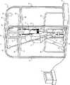
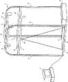
実施の形態1について説明する。まず、図1を参照して、本実施の形態1に係る歩行訓練システム1の構成について説明する。図1に示すように、歩行訓練システム1は、トレッドミル2と、制御装置3とを有する。<
トレッドミル2は、訓練者4が歩行訓練をするための装置である。トレッドミル2は、歩行訓練装置として機能する。制御装置3は、トレッドミル2を制御する装置である。制御装置3は、典型的には、PC(Personal Computer)である。しかしながら、制御装置3は、これに限られず、タブレット端末及びスマートフォン等の他の情報処理装置を利用するようにしてもよい。 The
トレッドミル2は、フレーム21と、ベルトコンベア22と、ロボット23と、免荷装置24と、モータボックス25と、一対の手すり26と、複数の縦枠部材27と、複数の上枠部材28、29とを有する。 The
フレーム21は、訓練者4の歩行訓練を補助する補助者5の両足の各々が乗せられる。フレーム21は、補助者5が両足の各々を乗せる足置部として機能する。フレーム21は、少なくともベルトコンベア22の両側に配置された一対の部分(後述の右枠部及び左枠部)を有する。これにより、補助者5は、ベルトコンベア22を跨ぐ形でフレーム21上に立ち、前方で歩行する訓練者4を両手で把持して支持することができる。なお、本実施の形態では、訓練者4が歩行によって進行する方向を「前方」と言い、その逆方向を「後方」と言う。よって、図1では、右方向が「前方」となり、左方向が「後方」となる。 The
ベルトコンベア22は、訓練者4によって歩行が行われる。ベルトコンベア22は、訓練者4が歩行するための歩行部として機能する。ベルトコンベア22は、制御装置3からの制御によって訓練者4を後方に送るようにそのベルトが回転される。言い換えると、ベルトコンベア22の上面が後方に向かって移動する。これにより、訓練者4が一定の位置で歩行を継続することを可能とする。 The
ロボット23は、訓練者4の歩行をアシストするロボットスーツである。ロボット23は、訓練者4の患側の脚に装着される。ロボット23は、制御装置3からの制御によって訓練者4の患側の脚の動作を補助する。ロボット23は、例えば、一定時間毎に訓練者4のひざ関節を屈曲させるように動作し、患側の脚について歩行時の動作を実現させる。 The
免荷装置24は、訓練者4を吊り下げる形で支持する。免荷装置24は、一端が上枠部材29に取り付けられている。免荷装置24は、他端がベルトの形状となっており、訓練者4の上半身に取り付けられる。これにより、訓練者4が歩行訓練時に姿勢を崩した場合であっても、訓練者4が立位姿勢を維持することを可能としている。 The
モータボックス25は、ベルトコンベア22の回転軸(図示せず)と、その回転軸を回転させるモータ(図示せず)とを有する。制御装置3からの制御によってモータボックス25内のモータが駆動されることで、ベルトコンベア22が動作する。 The
手すり26は、ベルトコンベア22の左右に設けられる。手すり26は、例えば、逆U字型であり、その2つの端部がフレーム21の上面に連結されている。これにより、訓練者4が左右の手すり26のそれぞれを左右の手のそれぞれで把持することで、立位姿勢を維持し易くしている。 The
縦枠部材27は、鉛直方向に延びる部材である。図1では、トレッドミル2が、その右前部、左前部、右後部、左後部に配置される4つの縦枠部材27を有する例について示しているが、縦枠部材27の位置及び数は、これに限られない。 The
上枠部材28は、縦枠部材27の上部で、縦枠部材27を連結する部材である。図1では、トレッドミル2が、4つの上枠部材28を有する例について示している。より具体的には、図1の例では、トレッドミル2は、右前部と左前部の縦枠部材27を連結する上枠部材28と、右後部と左後部の縦枠部材27を連結する上枠部材28と、右前部と右後部の縦枠部材27を連結する上枠部材28と、左前部と左後部の縦枠部材27を連結する上枠部材28とを有している。しかしながら、上枠部材28の数及び上枠部材28が接続対象とする縦枠部材27の組み合わせは、これに限られない。 The
上枠部材29は、縦枠部材27の最上部で、縦枠部材27を連結する部材である。言い換えると、上枠部材29は、上枠部材28よりも上部で、縦枠部材27を連結する部材である。図1では、トレッドミル2が、5つの上枠部材29を有する例について示している。より具体的には、図1の例では、トレッドミル2は、右前部と右後部の縦枠部材27を連結する上枠部材29と、左前部と左後部の縦枠部材27を連結する上枠部材29と、それらの上枠部材29間を連結する3つの上枠部材29とを有している。 The
上述したように、免荷装置24は、その一端が上枠部材29に接続されている。また、ロボット23も、上枠部材29とケーブルを介して接続されており、上枠部材29から吊り下げられる形で支持されている。これにより、訓練者4にかかるロボット23の荷重を低減している。 As described above, one end of the
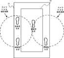
続いて、図2を参照して、本実施の形態1に係る歩行訓練システム1の異常検出方法について説明する。図2は、フレーム21及びベルトコンベア22の上面図である。 Then, with reference to FIG. 2, the abnormality detection method of the walking
トレッドミル2は、上述したように、フレーム21と、ベルトコンベア22とを有している。フレーム21は、例えば、図2に示すようにロの字型である。フレーム21の右枠部は、ベルトコンベア22よりも右側に配置されている。フレーム21の左枠部は、ベルトコンベア22よりも左側に配置されている。図2では、フレーム21の前枠部と後枠部がベルトコンベア22上に重複するように配置される例について示しているが、これに限られない。フレーム21の前枠部がベルトコンベア22の前端よりも前に配置されていてもよく、フレーム21の後枠部がベルトコンベア22の後端よりも後ろに配置されていてもよい。また、フレーム21は、右枠部と左枠部を有し、前枠部と後枠部を有さない構成としてもよい。 As described above, the
歩行訓練システム1は、このような構成において、フレーム21上に3つ以上の足が存在すると判定した場合に異常状態であると判定する。これは、例えば、図2に示すように、訓練者4が歩行訓練中に姿勢を崩し、訓練者4の片足がベルトコンベア22外のフレーム21に出てしまった状態である。このような状態では、訓練者4が歩行訓練を継続することは困難であり、一度、訓練者4の体勢を立て直す等する必要があるからである。 In such a configuration, the walking
そこで、歩行訓練システム1は、異常状態であると判定した場合、異常時制御を行う。歩行訓練システム1は、例えば、異常時制御として、ベルトコンベア22の速度を低下させる、ベルトコンベア22を停止させる、ロボット23の動作を停止させる、及び、訓練者4及び補助者5に対して警報を通知する等の制御のうち、少なくとも1つを実施する。 Therefore, when it is determined that the walking
ここで、歩行訓練システム1では、後述するように、フレーム21に荷重センサを配置することで、フレーム21の上面に対する訓練者4及び補助者5の足からの荷重を検出する。歩行訓練システム1は、フレーム21の上面に対して荷重が検出された場合にフレーム21上に足が存在すると判定する。よって、歩行訓練システム1は、原則、フレーム21上に3点以上の荷重が検出されている場合、フレーム21上に3つ以上の足が存在すると判定する。 Here, in the
しかしながら、補助者5からフレーム21に対する荷重のかけ具合によっては、補助者5のみからの荷重で、フレーム21上に3点以上の荷重がかかっているように見えてしまう可能性もある。例えば、土踏まずでは荷重が検出されず、つま先と、かかとが別々の荷重点として検出されてしまう場合である。この場合、何も考慮がなされていないと、訓練者4がフレーム21上に足を置いていないにも関わらず、補助者5のみの足からの荷重で異常状態であると誤判定されてしまう可能性がある。そこで、本実施の形態1では、次に説明する2つの方法のいずれかによって、そのような誤判定を回避する。 However, depending on how the load is applied to the
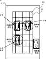
続いて、図3を参照して、第1の方法について説明する。図3に示すように、フレーム21上には、複数の荷重センサ201が碁盤目状に配置されている。すなわち、フレーム21上には、長方形の荷重センサ201が敷き詰められるように並べられて配置されている。なお、図3では、訓練者4の左足がフレーム21上に出てしまった例を示している。 Next, the first method will be described with reference to FIG. As shown in FIG. 3, a plurality of
複数の荷重センサ201のそれぞれは、フレーム21に対する荷重分布を検出する。制御装置3は、荷重センサ201によって独立した2つの荷重分布が検出された場合、その2つの荷重分布の中心間の長さが所定長よりも長いか否かを判定する。制御装置3は、2つの荷重分布の中心間の長さが所定長よりも長いと判定した場合、その2つの荷重分布を別々の荷重点として扱う。すなわち、制御装置3は、その2つ荷重分布のそれぞれを、訓練者4の足による荷重分布と補助者5の足による荷重分布とであると判定する。言い換えると、制御装置3は、フレーム21上に訓練者4の足と補助者の足が存在すると判定する。一方、制御装置3は、2つの荷重分布の中心間の長さが所定長以下であると判定した場合、その2つの荷重分布を1つの荷重点として扱う。すなわち、制御装置3は、その2つの荷重分布を、補助者5の足による1つの荷重分布であると判定する。言い換えると、制御装置3は、フレーム21上に補助者の足のみが存在すると判定する。 Each of the plurality of
なお、上述の所定長は、訓練者4と補助者5による荷重分布と、補助者5のみによる荷重分布とを識別できるだけの長さであれば、任意の値を設定することができるが、好ましくは、補助者5の足のサイズが設定される。 The above-mentioned predetermined length can be set to any value as long as it is long enough to distinguish between the load distribution by the trainer 4 and the
以上に説明した第1の方法によれば、図3に示すように、訓練者4と補助者5によって独立した3点以上の荷重が検出されており、フレーム21上に3つ以上の足が存在する場合と、補助者5のみによって独立した3点以上の荷重が検出されており、フレーム21上に3つ以上の足が存在しない場合とを識別することができる。 According to the first method described above, as shown in FIG. 3, three or more independent loads are detected by the trainer 4 and the
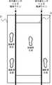
続いて、図4を参照して、第2の方法について説明する。上述したように、フレーム21上には、複数の荷重センサ201が碁盤目状に配置されている。なお、図4でも、訓練者4の左足がフレーム21上に出てしまった例を示している。 Next, the second method will be described with reference to FIG. As described above, a plurality of
制御装置3は、荷重センサ201によって独立した2つの荷重分布が検出された場合、その2つの荷重分布全体の長さが所定長よりも長いか否かを判定する。この荷重分布全体の長さは、例えば、一方の荷重分布の一端から他方の荷重分布の一端までの長さをとった場合に、最も長くなる長さとする。制御装置3は、2つの荷重分布全体の長さが所定長よりも長いと判定した場合、その2つの荷重分布を別々の荷重点として扱う。一方、制御装置3は、2つの荷重分布全体の長さが所定長以下であると判定した場合、その2つの荷重分布を1つの荷重点として扱う。なお、第2の方法においても、所定長は、第1の方法で説明した通りに設定してよい。 When two independent load distributions are detected by the
以上に説明した第2の方法によっても、図4に示すように、訓練者4と補助者5によって独立した3点以上の荷重が検出されており、フレーム21上に3つ以上の足が存在する場合と、補助者5のみによって独立した3点以上の荷重が検出されており、フレーム21上に3つ以上の足が存在しない場合とを識別することができる。 Also according to the second method described above, as shown in FIG. 4, three or more independent loads are detected by the trainer 4 and the
このように、2つの荷重分布間の長さが所定長よりも長い場合には、2つの足が存在すると判定し、2つの荷重分布間の長さが所定長以下である場合には、1つの足が存在すると判定することで、誤判定を回避することができる。そして、その判定における2つの荷重分布間の長さは、第1の方法で説明したように2つの荷重分布中心間の長さとしてもよく、第2の方法で説明したように2つの荷重分布全体の長さ(一方の荷重分布の端から他方の荷重分布の端までの長さ)としてもよい。なお、第1の方法及び第2の方法による判定は、フレーム21の右枠部と左枠部で独立して行われる。 Thus, when the length between the two load distributions is longer than the predetermined length, it is determined that there are two legs, and when the length between the two load distributions is equal to or less than the predetermined length, 1 By determining that there is one leg, it is possible to avoid erroneous determination. The length between the two load distributions in the determination may be the length between the two load distribution centers as described in the first method, and the two load distributions as described in the second method. The total length (the length from the end of one load distribution to the end of the other load distribution) may be used. Note that the determination by the first method and the second method is performed independently at the right frame portion and the left frame portion of the
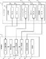
続いて、図5を参照して、本実施の形態1に係る歩行訓練システム1の制御系の構成について説明する。図5に示すように、トレッドミル2において、フレーム21は複数の荷重センサ201を有し、ベルトコンベア22はモータ202を有し、ロボット23はモータ203を有し、免荷装置24はモータ204を有する。 Then, with reference to FIG. 5, the structure of the control system of the walking
複数の荷重センサ201は、上述したようにフレーム21上に碁盤目状で配置される。複数の荷重センサ201のそれぞれは、フレーム21に対する荷重分布を検出(計測)し、検出した荷重分布を示す荷重分布情報を制御装置3に送信する。 The plurality of
モータ202は、上述のベルトコンベア22のベルトを回転させるモータである。モータ202は、上述のモータボックス25内のモータに相当する。モータ202は、制御装置3から受信した指令値に従って駆動し、ベルトコンベア22のベルトを回転させる。 The
モータ203は、ロボット23に屈曲動作を行わせる。モータ203は、制御装置3から受信した指令値に従って駆動し、ロボット23に屈曲動作を行わせる。制御装置3は、モータ203に対して一定時間毎にロボット23に屈曲動作を行わせるように指令値を送信する。これにより、上述したように、ロボット23は、一定時間毎に訓練者のひざ関節を屈曲させて、患側の脚について歩行時の動作を実現させる。 The
モータ204は、免荷装置24を上方に牽引する。モータ204は、制御装置3から受信した指令値に従って駆動し、免荷装置24を上方に牽引する。制御装置3は、訓練者4に対して免荷装置24を装着後に、免荷装置24を上方に牽引するように指令値を送信する。これにより、歩行訓練開始前に、訓練者4を立位姿勢とすることができる。 The
また、図5に示すように、制御装置3は、センサ値取得部31と、異常判定部32と、コンベア制御部33と、ロボット制御部34と、免荷装置制御部35と、記憶部36とを有する。制御装置3は、例えば、CPU(Central Processing Unit)を有し、上記各部31〜35の処理を実行させるプログラムをCPUによって実行することで、上記各部31〜35の機能を実現する。 As shown in FIG. 5, the
センサ値取得部31は、複数の荷重センサ201のそれぞれから送信された荷重分布情報を受信する。より具体的には、センサ値取得部31は、訓練者4による歩行訓練中に、一定時間毎に、複数の荷重センサ201のそれぞれから荷重分布情報を受信する。 The sensor
異常判定部32は、センサ値取得部31が受信した荷重分布情報に基づいて、フレーム21上に3つ以上の足が存在するか否かを判定する。異常判定部32は、フレーム21上に3つ以上の足が存在しないと判定した場合には、正常状態であると判定する。一方、異常判定部32は、フレーム21上に3つ以上の足が存在すると判定した場合には、異常状態であると判定する。なお、この異常状態の判定では、上述したように第1の方法又は第2の方法を利用して、誤判定を回避して異常状態を検出する。 The
コンベア制御部33は、ベルトコンベア22のモータ202を制御する指令値を生成し、トレッドミル2に送信する。コンベア制御部33は、訓練者4による歩行訓練中において、異常判定部32によって正常状態であると判定されている場合は、ベルトコンベア22のモータ202を回転させる指令値を生成してトレッドミル2に送信する。一方で、コンベア制御部33は、訓練者4による歩行訓練中において、異常判定部32によって異常状態であると判定された場合には、ベルトコンベア22のモータ202の回転速度を正常状態よりも低速にする指令値、又は、ベルトコンベア22のモータ202の回転を停止させる指令値を生成し、トレッドミル2に送信する。 The
ロボット制御部34は、ロボット23のモータ203を制御する指令値を生成してトレッドミル2に送信する。ロボット制御部34は、訓練者4による歩行訓練中において、異常判定部32によって正常状態であると判定されている場合は、一定時間毎にロボット23に屈曲動作を行わせる指令値を生成してトレッドミル2に送信する。一方、ロボット制御部34は、訓練者4による歩行訓練中において、異常判定部32によって異常状態であると判定された場合には、ロボット23の屈曲動作を停止させる指令値を生成してトレッドミル2に送信する。 The
免荷装置制御部35は、免荷装置24のモータ204を制御する指令値を生成してトレッドミル2に送信する。免荷装置制御部35は、訓練者4に対する免荷装置24の装着後に、免荷装置24を上方に牽引する指令値を生成してトレッドミル2に送信する。 The unloading
記憶部36は、制御装置3によるトレッドミル2の制御に利用される各種情報が格納される。記憶部36は、少なくとも1つの記憶装置を含む。記憶装置は、例えば、メモリ又はハードディスク等である。 The
より具体的には、記憶部36には、センサ位置情報301と、センササイズ情報302と、足サイズ情報303とが予め格納される。センサ位置情報301は、複数の荷重センサ201のそれぞれについて、フレーム21における位置を示す情報である。センササイズ情報302は、荷重センサ201のサイズを示す情報である。 More specifically,
異常判定部32は、センサ位置情報301及びセンササイズ情報302を利用して、上述の荷重分布中心間の長さ又は荷重分布全体の長さを算出する。例えば、異常判定部32は、2つの荷重センサ201からの荷重分布情報のそれぞれが荷重分布を示している場合、センサ位置情報301に基づいて、その2つの荷重センサ201の間に他の荷重センサ201が存在するか否かを判定する。そして、異常判定部32は、その2つの荷重センサ201の間に荷重センサ201が存在すると判定された場合には、異常判定部32は、その2つの荷重センサ201で検出された荷重分布における長さに、その2つの荷重センサ201の間に存在する荷重センサ201の長さを加算することで、荷重分布中心間の長さ又は荷重分布全体の長さを算出する。このときに、荷重センサ201の長さは、センササイズ情報302が示す荷重センサ201のサイズが利用される。 The
また、荷重センサ201の位置の特定に関しては、例えば、センサ位置情報301を、複数の荷重センサ201のそれぞれについて、荷重センサ201を一意に特定する識別子と、その荷重センサ201の位置とを対応付けて示す情報とする。そして、荷重センサ201は、その荷重センサ201の識別子を荷重分布情報に含めて送信するようにする。これによれば、異常判定部32は、センサ位置情報301に基づいて、荷重分布情報に含まれる識別子からその荷重分布情報を送信した荷重センサ201の位置を特定可能となる。 For specifying the position of the
足サイズ情報303は、補助者5の足のサイズを示す情報である。この足サイズ情報303が示す足のサイズは、上述の第1の方法及び第2の方法において所定長を補助者5の足のサイズとする場合に利用される。ここで、足サイズ情報303は、例えば、補助者5が制御装置3の入力装置(図示せず)によって制御装置3に対して事前に入力したサイズを示すように生成して記憶部36に格納する。また、足サイズ情報303は、例えば、歩行訓練の開始前に、補助者5のみがフレーム21上に乗って、その時に荷重センサ201によって検出された荷重分布の長さを示すように生成して記憶部36に格納するようにしてもよい。 The
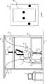
続いて、図6A〜6Eを参照して、本実施の形態1に係る歩行訓練システム1における歩行訓練の手順の一例について説明する。図6A〜6Eでは、左側において、歩行訓練システム1を側面から見た状態を示し、右側において、フレーム21及びベルトコンベア22の上面の状態を示している。 Subsequently, an example of a walking training procedure in the
まず、図6Aに示すように、訓練者4は、車椅子に乗ってトレッドミル2の傍まで来る。車椅子は、補助者5によって押されることでトレッドミル2の傍まで移動される。このときには、フレーム21及びベルトコンベア22の上には何もない状態である。 First, as shown in FIG. 6A, the trainer 4 comes to the
次に、図6Bに示すように、補助者5は、訓練者4が乗った車椅子を押してトレッドミル2に乗り込む。これにより、訓練者4が乗った車椅子と、補助者5とがベルトコンベア22上に乗った状態となる。ベルトコンベア22には、車椅子からの荷重と、車椅子の後方において補助者5の両足からの2点の荷重がかかった状態となる。 Next, as shown in FIG. 6B, the
次に、図6Cに示すように、補助者5は、訓練者4の前方に回り、訓練者4の患側の脚にロボット23を装着する。このときには、訓練者4が乗った車椅子と、補助者5とがベルトコンベア22上に乗った状態である。ただし、ベルトコンベア22には、車椅子の前方において、補助者5の両足からの2点の荷重がかかった状態となる。 Next, as shown in FIG. 6C, the
次に、図6Dに示すように、補助者5は、訓練者4に免荷装置24を装着し、訓練者4を立たせる。より具体的には、補助者5は、訓練者4に免荷装置24を装着し、制御装置3の入力装置を介して、免荷装置24を上方に牽引するように指示する入力を行う。制御装置3の免荷装置制御部35は、補助者5からの入力に応じて、免荷装置24を上方に牽引する指令値を生成してトレッドミル2に送信する。これにより、免荷装置24のモータ204が駆動して、免荷装置24が訓練者4を上方に引き上げ、訓練者4が立位姿勢とされる。そして、補助者5は、車椅子をトレッドミル2の外に退かす。このときには、訓練者4と補助者5とがベルトコンベア22上に乗った状態となる。すなわち、ベルトコンベア2には、訓練者4の両足からの2点の荷重と、その前方で補助者5の両足からの2点の荷重とがかかった状態となる。 Next, as illustrated in FIG. 6D, the
次に、図6Eに示すように、補助者5は、訓練者4の歩行訓練を開始する。より具体的には、補助者5は、制御装置3の入力装置を介して、歩行訓練の開始を指示する入力を行う。制御装置3の異常判定部32は、補助者5からの入力に応じて、複数の荷重センサ201から受信した荷重分布情報に基づいた異常状態の判定を開始する。また、制御装置3のコンベア制御部33は、補助者5からの入力に応じて、ベルトコンベア22により訓練者4を後方に送るようにモータ202を駆動する。また、制御装置3のロボット制御部34は、補助者5からの入力に応じて、訓練者4の患側の脚の屈曲させるようにロボット23のモータ203の制御を開始する。補助者5は、訓練者4の後方に回り、フレーム21上に立って訓練者4を支持する。このときに、補助者5が訓練者4を支持してから歩行訓練が開始されるようにするために、制御装置3は、歩行訓練の開始を指示する入力が行われてから所定の時間が経過した後に、その入力に応じた上述の各制御を開始するようにしてもよい。 Next, as illustrated in FIG. 6E, the
続いて、図7を参照して、本実施の形態1に係る歩行訓練システム1の処理について説明する。 Then, with reference to FIG. 7, the process of the walking
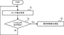
センサ値取得部31は、一定時間毎に、複数の荷重センサ201のそれぞれから送信される荷重分布情報を受信する(S1)。異常判定部32は、センサ値取得部31が受信した荷重分布情報に基づいて、フレーム21上において3つ以上の足が存在するか否かを判定する(S2)。 The sensor
異常判定部32は、フレーム21において3つ以上の足が存在しないと判定した場合(S2:No)、通常状態であると判定し、一定時間毎の荷重分布情報に基づいた判定を継続する(S1、S2)。一方、異常判定部32は、フレーム21において3つ以上の足が存在すると判定した場合(S2:Yes)、異常状態であると判定する。この場合、コンベア制御部33及びロボット制御部34は、上述したように異常時制御を実施する(S3)。 If it is determined that there are not three or more legs in the frame 21 (S2: No), the
具体的には、コンベア制御部33は、ベルトコンベア22の速度を低下させる、又は、ベルトコンベア22を停止させる制御を実施する。また、ロボット制御部34は、ロボット23の動作を停止させる制御を実施する。 Specifically, the
また、訓練者4及び補助者5に対して警報の通知を実施するようにしてもよい。この場合には、トレッドミル2は警報装置を有するようにし、制御装置3は警報装置制御部を有するようにする。警報装置制御部は、警報装置に警報の通知を指示する指示情報を送信する。警報装置は、警報装置制御部からの指示情報に応じて、訓練者4及び補助者5に対して警報を通知する。なお、警報は、光及び音等のうち、任意の方法によって通知するようにしてよい。警報を光で通知する場合には、警報装置は光ランプとして、制御装置3からの指示情報に応じて光ランプを点灯する。また、警報を音で通知する場合には、警報装置はスピーカーとして、制御装置3からの指示情報に応じてスピーカーから警告音を出力する。 Moreover, you may make it implement the alert notification with respect to the trainer 4 and the
以上に説明したように、本実施の形態1では、異常判定部32は、荷重センサ201による計測結果に基づいて、フレーム21上に3つ以上の足が存在するか否かを判定する。そして、コンベア制御部33及びロボット制御部34は、異常判定部32によって3つ以上の足が存在すると判定された場合、異常時制御を行うようにしている。これによれば、訓練者4が歩行に失敗してコンベアから外れてしまった状況を検出することができる。すなわち、歩行訓練時における異常状態を検出することができる。 As described above, in the first embodiment, the
また、本実施の形態1では、荷重センサ201によってフレーム21に対する足からの荷重を計測し、異常判定部32は、荷重センサ201によって荷重が計測された場合にフレーム21上に足が存在すると判定するようにしている。これによれば、光学的なセンサを利用する場合と比較して、汚れに強く、かつ低コストなシステムを実現することができる。 In the first embodiment, the
<発明の実施の形態2>
続いて、実施の形態2について説明する。以下、実施の形態1と同様の内容については、適宜省略して説明する。実施の形態1では、フレーム21の全範囲に碁盤目状に荷重センサ201を敷き詰める例について説明した。しかしながら、補助者5は訓練者4の後方で訓練者4を両手で支持しているため、フレーム21において補助者5が足を置く範囲は後方寄りの一定範囲に限られる。また、訓練者4も補助者5によって両手で支持されているため、補助者5の非常に近くに位置する。そのため、訓練者4が姿勢を崩してフレーム21に足が置かれる場合も、訓練者4の足は補助者5の足の近くに位置する可能性が高い。<
Next, the second embodiment will be described. Hereinafter, the same contents as those in the first embodiment will be omitted as appropriate. In the first embodiment, the example in which the
すなわち、実施の形態1では、2つの荷重分布が検出された場合に、その2つの荷重分布の長さに基づいて、補助者5のみによる荷重分布であるか、訓練者4と補助者5による荷重分布であるかを判定するようにしているが、そのような判定を行うべき範囲は、訓練者4と補助者5の両方から足が置かれる可能性のあるフレーム21の後方寄りの一定範囲で足りる。 That is, in the first embodiment, when two load distributions are detected, based on the lengths of the two load distributions, whether the load distribution is only by the
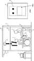
そこで、本実施の形態2では、図8に示すように、フレーム21の右枠部と左枠部のそれぞれの後方寄りの所定範囲のみに碁盤目状に複数の荷重センサ201を敷き詰めて配置する。この所定範囲は、例えば、ベルトコンベア21の前後方向の中間よりも後ろ側の範囲としてもよいが、これに限られない。なお、この複数の荷重センサ201によって検出された荷重分布に基づいて3つ以上の足が存在するか否かを判定する方法は、実施の形態1と同様であるため、説明を省略する。 Therefore, in the second embodiment, as shown in FIG. 8, a plurality of
また、本実施の形態2では、フレーム21において2つのON/OFFセンサ205を有する。フレーム21の前側部(前枠部と、右枠部と左枠部のそれぞれの荷重センサ201が配置されていない範囲)は、コの字型の板状部材とされており、その下に1つのON/OFFセンサ205が配置されている。これにより、フレーム21の前側部(コの字型の板状部材)に足が置かれて押された場合には、ON/OFFセンサ205がONとなり、足が置かれておらず押されていない場合には、ON/OFFセンサ205がOFFとなる。 In the second embodiment, the
フレーム21の前側部は、補助者5が荷重をかける可能性は極めて低く、訓練者4のみが姿勢を崩した場合に荷重をかける可能性が非常に高い。そのため、フレーム21の前側部において訓練者4からの3点目の荷重がかけられたことの検出は、このようにON/OFFセンサ205によって単純にフレーム21の前側部が押されたか否かのみを検出することで足りる。 The front side portion of the
また、本実施の形態2では、フレーム21の後枠部も一の字型の板状部材とされており、その下にもう1つのON/OFFセンサ205が配置されている。これにより、フレーム21の後枠部が押された場合には、ON/OFFセンサ205がONとなり、押されていない場合には、ON/OFFセンサ205がOFFとなる。 In the second embodiment, the rear frame portion of the
これによれば、歩行訓練中に、訓練者4及び補助者5以外の第三者がトレッドミル2上に侵入する異常も検出することができる。 According to this, it is also possible to detect an abnormality in which a third party other than the trainer 4 and the
続いて、図9を参照して、本実施の形態2に係る歩行訓練システム1の制御系の構成について説明する。図9に示すように、本実施の形態2では、実施の形態1と比較して、トレッドミル2において、フレーム21がさらに2つのON/OFFセンサ205を有する点が異なる。また、上述したように、本実施の形態2では、実施の形態1と比較して、荷重センサ201の数が少ない。 Then, with reference to FIG. 9, the structure of the control system of the walking
2つのON/OFFセンサ205のそれぞれは、フレーム21の前側部及び後枠部のそれぞれに足が乗せられておらず、OFFにされている場合には、OFF状態であることを示す状態通知情報を制御装置3に送信する。一方、2つのON/OFFセンサ205のそれぞれは、フレーム21の前側部及び後枠部のそれぞれに対して足が乗せられており、ONにされている場合には、ON状態であることを示す状態通知情報を制御装置3に送信する。なお、ON/OFFセンサ205は、単純にON又はOFFを検出するだけのセンサであるため、荷重分布を検出する荷重センサ201と比較して安価なセンサとなる。 Each of the two ON /
本実施の形態2では、センサ値取得部31は、複数の荷重センサ201に加え、さらに2つのON/OFFセンサ205のそれぞれから送信された状態通知情報も受信する。 In the second embodiment, the sensor
本実施の形態2では、異常判定部32は、実施の形態1と同様に、センサ値取得部31が受信した荷重分布情報に基づいて、フレーム21上に3つ以上の足が存在するか否かを判定する。ここで、本実施の形態2では、異常判定部32は、さらに、センサ値取得部31が受信した状態通知情報に基づいて、フレーム21上に3つ以上の足が存在するか否か判定する。 In the second embodiment, the
より具体的には、異常判定部32は、2つの状態通知情報の少なくとも1つがON状態であることを示している場合には、フレーム21上に3つ以上の足が存在すると判定する。すなわち、異常判定部32は、異常状態であると判定する。これは、上述したように、ON/OFFセンサ205が押されてON状態となっている状態は、補助者5以外がフレーム21に入っている状態となるからである。一方、異常判定部32は、2つの状態通知情報のいずれもOFF状態であることを示している場合には、フレーム21上に3つ以上の足が存在しないと判定する。すなわち、正常状態であると判定する(ただし、荷重分布情報に基づいて異常状態と判定されていない場合)。また、2つの状態通知情報の少なくとも1つがON状態であるか否かのみの判定に限られず、異常判定部32は、センサ値取得部31が受信した荷重分布情報に基づいてフレーム21上に2つの足が存在すると判定された状態で、2つの状態通知情報の少なくとも1つがON状態であることを示している場合に、3つ以上の足が存在すると判定し、それ以外の場合には、3つ以上の足が存在しないと判定するようにしてもよい。 More specifically, the
以上に説明したように、本実施の形態2では、複数の荷重センサ201は、フレーム21において訓練者4の進行方向とは逆方向(後方)寄りの所定範囲内のみに並べて配置されるようにしている。これによれば、訓練者4と補助者5の両方が足を置く可能性がある範囲のみ荷重センサ201を配置して荷重分布に基づいた詳細な判定を行うようにしているため、検出精度を低下させることなく、荷重センサ201の数を低減してコストを低減することができる。 As described above, in the second embodiment, the plurality of
また、本実施の形態2では、歩行訓練システム1は、フレーム21において複数の荷重センサ201が配置される範囲外で足が乗せられた場合にONとなり、足が乗せられていない場合にOFFとなるON/OFFセンサ205を有している。異常判定部32は、複数の荷重センサ201による計測結果に基づいてフレーム上21に2つの足が存在すると判定された状態で、ON/OFFセンサ205がONとなった場合にフレーム上21に3つ以上の足が存在すると判定するようにしている。これによれば、訓練者4のみが足を置く可能性がある範囲のみについて安価なON/OFFセンサ205によって、その訓練者4の足の存在を検出するようにしているため、検出精度を低下させることなく、コストを低減することができる。 In the second embodiment, the walking
<発明の実施の形態3>
続いて、実施の形態3について説明する。以下、実施の形態1と同様の内容については、適宜省略して説明する。実施の形態1では、フレーム21において3つ以上の足が存在すると判定した場合に異常状態であると判定するようにしていた。しかしながら、補助者5が姿勢を崩して、ベルトコンベア22内に入ってしまった場合も、補助者5による訓練者4の支持が困難となり、訓練者4が歩行訓練を継続することが困難な状態となる。そこで、本実施の形態3では、このような状態を異常状態として検出可能な歩行訓練システム1について説明する。<Third Embodiment of the Invention>
Subsequently,
本実施の形態3は、実施の形態1と比較し、複数の荷重センサ201がフレーム21に配置されているのではなく、ベルトコンベア22に配置される点が異なる。荷重センサ201は、ベルトコンベア22の上側のベルトの下に配置する。これにより、移動するベルト上においても荷重を検出可能とする。複数の荷重センサ201は、ベルトコンベア22におけるフレーム21で囲まれた範囲内に碁盤目状に配置される。 The third embodiment is different from the first embodiment in that a plurality of
なお、異常状態の検出方法及びそれに応じた異常時処理については、実施の形態1と同様であるため、説明を省略する。 The method for detecting an abnormal state and the processing at the time of abnormality corresponding thereto are the same as those in the first embodiment, and thus description thereof is omitted.
以上に説明したように、本実施の形態3では、異常判定部32は、荷重センサ201による計測結果に基づいて、ベルトコンベア22上に3つ以上の足が存在するか否かを判定する。そして、コンベア制御部33及びロボット制御部34は、異常判定部32によって3つ以上の足が存在すると判定された場合、異常時制御を行うようにしている。これによれば、補助者5がフレーム21から外れてしまった状況を検出することができる。すなわち、歩行訓練時における異常状態を検出することができる。 As described above, in the third embodiment, the
なお、本実施の形態3は、実施の形態1又は実施の形態2と組み合わせて実施することも可能である。すなわち、実施の形態1又は実施の形態2において、さらに、実施の形態3として説明したようにベルトコンベア22に3つ以上の足が存在するか否かを判定するようにしてもよい。 Note that
ここで、実施の形態1又は実施の形態2において、本実施の形態3を組み合わせずとも、ベルトコンベア22に3つ以上の足が存在するか否かを判定するようにしてもよい。すなわち、異常判定部32は、フレーム21上において1点のみで荷重分布が検出されるようになった場合、及び、フレーム21上において荷重分布が全く検出されなくなった場合に、補助者5の足がベルトコンベア22内に入り、ベルトコンベア22に3つ以上の足が存在すると判定するようにしてもよい。そして、異常判定部32によってベルトコンベア22に3つ以上の足が存在すると判定された場合、コンベア制御部33及びロボット制御部34は、異常時処理を実施するようにしてもよい。 Here, in the first embodiment or the second embodiment, it may be determined whether or not there are three or more legs on the
<発明の実施の形態4>
続いて、実施の形態4について説明する。以下、実施の形態1と同様の内容については、適宜省略して説明する。実施の形態1〜3では、荷重センサ201による計測された荷重を利用して、フレーム21上またはベルトコンベア22上において3点以上で足が存在するか否かを判定するようにしていたが、フレーム21及びベルトコンベア22上の足の存在状態として計測する内容は荷重のみに限られない。フレーム21上またはベルトコンベア22上において3点以上で足が存在するか否かを判定することができるのであれば、他の内容を計測するようにしてよい。本実施の形態4では、フレーム21及びベルトコンベア22上の足の存在状態を赤外線センサによって計測する例について説明する。<Embodiment 4 of the Invention>
Subsequently, Embodiment 4 will be described. Hereinafter, the same contents as those in the first embodiment will be omitted as appropriate. In the first to third embodiments, the load measured by the
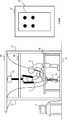
図11を参照して、本実施の形態4に係る歩行訓練システム1の構成について説明する。図11に示すように、本実施の形態4では、トレッドミル2は、実施の形態1と比較して、複数の荷重センサ201に代えて、複数の赤外線センサ206を有する。なお、図11では、本実施の形態4の特徴を明確にするために、訓練者4、補助者5、ロボット23、免荷装置24、及び手すり26の図示は省略している。 With reference to FIG. 11, the structure of the walking
複数の赤外線センサ206は、フレーム21とベルトコンベア22の境界を上方から観測するように設置される。複数の赤外線センサ206は、フレーム21とベルトコンベア22の境界を、それぞれが一定間隔毎に観測するように設置される。例えば、このフレーム21とベルトコンベア22の境界における観測点の間隔と、複数の赤外線センサ206が配置される間隔とは同一の間隔となる。複数の赤外線センサ206は、例えば、図11に示すように、フレーム21とベルトコンベア22の境界と平行するように、上枠部材28の下部に一列に配置される。この上枠部材28は、例えば、右前部と右後部の縦枠部材27を連結するものとなる。なお、複数の赤外線センサ206は、フレーム21とベルトコンベア22の境界を観測することができれば、図11に例示する配置に限られない。例えば、上枠部材29に配置するようにしてもよく、他のトレッドミル2上の部材に配置するようにしてもよい。 The plurality of
なお、図11では、赤外線センサ206の配置を明確にするために、フレーム21の右枠部と、ベルトコンベア22との境界を観測する複数の赤外線センサ206のみを図示しているが、トレッドミル2は、フレーム21の左枠部と、ベルトコンベア22との境界を観測する複数の赤外線センサ206も同様に有する。 In FIG. 11, only a plurality of
続いて、図12〜15を参照して、本実施の形態4に係る歩行訓練システム1の異常検出方法について説明する。図12は、フレーム21及びベルトコンベア22の上面図である。 Then, with reference to FIGS. 12-15, the abnormality detection method of the walking
上述したように、トレッドミル2は、フレーム21の右枠部とベルトコンベア22の境界と、フレーム21の左枠部とベルトコンベア22の境界のそれぞれを観測するように複数の赤外線センサ206を有する。そのため、複数の赤外線センサ206による観測ラインが、フレーム21の右枠部とベルトコンベア22の境界と、フレーム21の左枠部とベルトコンベア22の境界のそれぞれに形成される。 As described above, the
これによれば、訓練者4によって歩行訓練が正常に行われている場合には、赤外線センサ206の観測ラインが、補助者5の左右の足のそれぞれにより2か所で遮断される。一方、訓練者4が姿勢を崩して訓練者4の片足がフレーム21に出てしまった場合には、赤外線センサ206の観測ラインが3か所で遮断されることになる。すなわち、歩行訓練システム1は、赤外線センサ206によって赤外線の遮断が検出された場合にフレーム21上に足が存在すると判定する。 According to this, when walking training is normally performed by the trainee 4, the observation line of the
よって、歩行訓練システム1は、原則、赤外線センサ206の観測ラインが3か所以上で遮断された場合に、フレーム21上に3以上の足が存在すると判定する。これは、例えば、図12に示すように、訓練者4が姿勢を崩し、訓練者4の片足がベルトコンベア22外のフレーム21に出てしまった状態である。 Therefore, in principle, the walking
図13〜15を参照して、より具体的な例について説明する。図13〜15は、フレーム21の左枠部とベルトコンベア22との境界における観測ラインの状態の一例を示す図である。なお、ここでは、フレーム21の右枠部とベルトコンベア22との境界における観測ラインは、補助者5の右足により1か所だけ遮断されているものとする。 A more specific example will be described with reference to FIGS. 13-15 is a figure which shows an example of the state of the observation line in the boundary of the left frame part of the
図13に示すように、補助者5の左足によって、フレーム21の左枠部とベルトコンベア22との境界における観測ラインが1か所で遮断されている場合、合計で赤外線センサ206の観測ラインが2か所で遮断されていることになる。この場合は、歩行訓練システム1は、正常状態であると判定する。 As shown in FIG. 13, when the observation line at the boundary between the left frame portion of the
図14に示すように、訓練者4の左足と補助者5の左足によって、フレーム21の左枠部とベルトコンベア22との境界における観測ラインが2か所で遮断されている場合、合計で赤外線センサ206の観測ラインが3か所で遮断されていることになる。この場合は、歩行訓練システム1は、異常状態であると判定する。 As shown in FIG. 14, when the observation foot at the boundary between the left frame portion of the
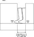
ここで、図15に示すように、訓練者4の左足と補助者5の左足とが近くに位置し、訓練者4の左足と補助者5の左足によって、フレーム21の左枠部とベルトコンベア22との境界における観測ラインが遮断されている場合、1か所で遮断されているように見える場合がある。すなわち、合計で赤外線センサ206の観測ラインが2か所で遮断されているように見える場合がある。例えば、連続する赤外線センサ206の赤外線が遮断された場合である。 Here, as shown in FIG. 15, the left foot of the trainer 4 and the left foot of the
この場合、何も考慮がなされていないと、訓練者4がフレーム21上に足を置いているにも関わらず、正常状態であると誤判定されてしまう可能性がある。そこで、本実施の形態4では、次に説明する方法によって、そのような誤判定を回避する。 In this case, if no consideration is given, it may be erroneously determined that the trainee 4 is in the normal state even though the trainer 4 is on the
複数の赤外線センサ206のそれぞれは、フレーム21とベルトコンベア22の境界に向けて赤外線を照射し、照射する赤外線が足によって遮断されているか否かを検出する。複数の赤外線センサ206のそれぞれは、例えば、反射型の赤外線センサ206である。 Each of the plurality of
制御装置3は、観測ラインにおいて2か所以上の非連続な赤外線センサ206において赤外線が遮断されている場合、その観測ラインの2か所以上が遮断されていると判定する。これは、例えば、図14に示す場合である。 When the infrared rays are blocked by two or more discontinuous
制御装置3は、観測ラインにおいて2つ以上の連続する赤外線センサ206において赤外線が遮断されている場合、赤外線が遮断されている2つ以上の赤外線センサ206のうち、両端の2つの赤外線センサ206間の長さが所定長よりも長いか否かを判定する。言い換えると、制御装置3は、赤外線が遮断されている長さが所定長よりも長いか否かを判定する。制御装置3は、2つの赤外線センサ206間の長さが所定長よりも長いと判定した場合、訓練者4と補助者5のそれぞれの足により2か所以上が遮断されていると判定する。言い換えると、制御装置3は、フレーム21上に訓練者4の足と補助者の足が存在すると判定する。これは、例えば、図15に示す場合である。一方、制御装置3は、2つの赤外線センサ206間の長さが所定長以下であると判定した場合、補助者5のみの足により1か所が遮断されていると判定する。言い換えると、制御装置3は、フレーム21上に補助者5の足のみが存在すると判定する。これは、例えば、図13に示す場合である。 When the infrared ray is blocked by two or more continuous
なお、上述の所定長は、訓練者4と補助者5による足によって赤外線が遮断される長さと、補助者5のみによって赤外線が遮断される長さとを識別できるだけの長さであれば、任意の値を設定することができるが、好ましくは、補助者5の足のサイズが設定される。 The above-mentioned predetermined length is an arbitrary length as long as it can distinguish between the length of the infrared rays blocked by the feet of the trainee 4 and the
続いて、図16を参照して、本実施の形態4に係る歩行訓練システム1の制御系の構成について説明する。図16に示すように、本実施の形態4では、実施の形態1と比較して、トレッドミル2において、フレーム21が複数の荷重センサ201を有さず、上枠部材28が複数の赤外線センサ206を有する。 Then, with reference to FIG. 16, the structure of the control system of the walking
複数の赤外線センサ206のそれぞれは、赤外線が遮断されているか否かを示す状態通知情報を制御装置3に送信する。本実施の形態4では、センサ値取得部31は、実施の形態1と比較して、複数の荷重センサ201に代えて、複数の赤外線センサ206から送信された状態通知情報を受信する。 Each of the plurality of
本実施の形態4では、異常判定部32は、センサ値取得部31が受信した状態通知情報に基づいて、フレーム21上に3つ以上の足が存在するか否かを判定する。すなわち、異常判定部32は、3か所以上で赤外線が遮断されているか否かを判定する。異常判定部32は、3か所以上で赤外線が遮断されていないと判定した場合、正常状態であると判定する。一方、異常判定部32は、3か所以上で赤外線が遮断されていると判定した場合、異常状態であると判定する。 In the fourth embodiment, the
また、本実施の形態4では、センササイズ情報302に代えて、センサ間隔情報304が予め格納される。また、本実施の形態4では、センサ位置情報301は、上枠部材28における複数の赤外線センサ206のそれぞれの位置を示す情報となる。 In the fourth embodiment,
よって、異常判定部32は、センサ位置情報301及びセンサ間隔情報304を利用して、3か所以上で赤外線が遮断されているか否かを判定する。例えば、異常判定部32は、センサ位置情報301に基づいて、赤外線が遮断された赤外線センサ206が連続して配置されたものであるか否かを判定する。また、異常判定部32は、2つの赤外線センサ206間の長さを算出する場合に、センサ位置情報301に基づいて、その2つの赤外線センサ206間に存在する赤外線センサ206の数を算出する。そして、異常判定部32は、センサ間隔情報304に基づいて、その赤外線センサ206の数に応じた長さを、その2つの赤外線センサ206間の距離として算出する。すなわち、例えば、((2つの赤外線センサ206間に存在する赤外線センサ206の数+1)×センサ間隔情報304が示す赤外線センサ206間の長さ)が、その2つの赤外線センサ206間の長さとして算出される。 Therefore, the
なお、赤外線センサ206の位置の特定に関しては、実施の形態1と同様に、例えば、センサ位置情報301を、複数の赤外線センサ206のそれぞれについて、赤外線センサ206を一意に特定する識別子と、その赤外線センサ206の位置とを対応付けて示す情報とする。そして、赤外線センサ206は、その赤外線センサ206の識別子を状態通知情報に含めて送信するようにすることで、異常判定部32が、センサ位置情報301に基づいて、状態通知情報に含まれる識別子からその状態通知情報を送信した赤外線センサ206の位置を特定可能とすればよい。 As for the position of the
なお、足サイズ情報303については、実施の形態1と同様である。すなわち、上述の所定長を補助者5の足のサイズとする場合に利用される。 The
なお、以上の説明では、足の存在状態を計測する光電センサとして赤外線センサ206を使用する例について説明したが、これに限られない。赤外線以外の光によって足の存在状態を計測する反射型の光電センサを利用するようにしてもよい。 In the above description, the example in which the
以上に説明したように、本実施の形態4では、ベルトコンベア22とフレーム21の境界を観測する複数の赤外線センサ206を有している。そして、赤外線センサ206によって赤外線の遮断が検出された場合にフレーム21上に足が存在すると判定するようにしている。このように、荷重センサ201以外のセンサによっても、歩行訓練中の異常状態を検出することも可能である。 As described above, the fourth embodiment includes a plurality of
また、本実施の形態4では、さらに、異常判定部32は、1か所のみで赤外線が遮断されるようになった場合、及び、赤外線が全く遮断されなくなった場合に、補助者5の足がベルトコンベア22内に入り、ベルトコンベア22に3つ以上の足が存在すると判定するようにしてもよい。そして、異常判定部32によってベルトコンベア22に3つ以上の足が存在すると判定された場合、コンベア制御部33及びロボット制御部34は、異常時処理を実施するようにしてもよい。 Further, in the fourth embodiment, the
<発明の実施の形態5>
続いて、実施の形態5について説明する。以下、実施の形態1と同様の内容については、適宜省略して説明する。実施の形態4では、荷重以外で、フレーム21及びベルトコンベア22上の足の存在状態として計測する内容として、赤外線センサ206による計測結果を利用する例について説明したが、これ以外の計測内容を利用することもできる。本実施の形態5では、フレーム21及びベルトコンベア22上の足の存在状態をカメラによって計測する例について説明する。<
Next, a fifth embodiment will be described. Hereinafter, the same contents as those in the first embodiment will be omitted as appropriate. In the fourth embodiment, the example in which the measurement result by the
図17を参照して、本実施の形態5に係る歩行訓練システム1の構成について説明する。図17に示すように、本実施の形態5では、トレッドミル2は、実施の形態1と比較して、複数の荷重センサ201に代えて、カメラ207を有する。なお、図17では、本実施の形態5の特徴を明確にするために、訓練者4、補助者5、ロボット23、免荷装置24、及び手すり26の図示は省略している。 With reference to FIG. 17, the structure of the walking
カメラ207は、フレーム21を上方から観測するように設置される。カメラ207は、例えば、図17に示すように、上枠部材28の下部に配置される。この上枠部材28は、例えば、右前部の縦枠部材27と右後部の縦枠部材27とを連結するものとなる。なお、カメラ207は、フレーム21を観測することができれば、図17に例示する配置に限られない。例えば、上枠部材29に配置するようにしてもよく、他のトレッドミル2上の部材に配置するようにしてもよい。 The
なお、図17では、カメラ207の配置を明確にするために、フレーム21の右枠部を観測するカメラ207のみを図示しているが、トレッドミル2は、フレーム21の左枠部を観測するカメラ207も同様に有する。 In FIG. 17, only the
続いて、図18を参照して、本実施の形態5に係る歩行訓練システム1の異常検出方法について説明する。図18は、フレーム21及びベルトコンベア22の上面図である。 Then, with reference to FIG. 18, the abnormality detection method of the walking
上述したように、トレッドミル2は、フレーム21の右枠部及び左枠部のそれぞれを観測するように2つのカメラ207を有する。そのため、フレーム21の右枠部及び左枠部のそれぞれが、2つのカメラ207のそれぞれの観測範囲に含まれる。 As described above, the
2つのカメラ207のそれぞれは、フレーム21の右枠部及び左枠部を撮像する。制御装置3は、2つのカメラ207による撮像結果に基づいて、フレーム21上に存在する足を認識する。なお、この足の認識は、パターンマッチング等の一般的な画像認識技術のうち、任意の技術を採用するようにしてよい。 Each of the two
制御装置3は、カメラ207による撮像結果に基づいて3つ以上の足が認識されない場合、フレーム21に3つ以上の足が存在しないことになる。この場合、制御装置3は、正常状態であると判定する。一方、制御装置3は、カメラ207による撮像結果に基づいて3つ以上の足が認識される場合、フレーム21に3つ以上の足が存在することになる。この場合、制御装置3は、異常状態であると判定する。 When three or more feet are not recognized based on the imaging result of the
続いて、図19を参照して、本実施の形態5に係る歩行訓練システム1の制御系の構成について説明する。図19に示すように、本実施の形態5では、実施の形態1と比較して、トレッドミル2において、フレーム21が複数の荷重センサ201を有さず、上枠部材28が2つのカメラ207を有する。 Then, with reference to FIG. 19, the structure of the control system of the walking
2つのカメラ207のそれぞれは、撮像によって生成したフレーム21の画像を示す画像情報を制御装置3に送信する。本実施の形態4では、センサ値取得部31は、複数の荷重センサ201に代えて、2つのカメラ207から送信された画像情報を受信する。 Each of the two
本実施の形態4では、異常判定部32は、センサ値取得部31が受信した画像情報が示す画像を解析して、フレーム21上に3つ以上の足が存在するか否かを判定する。すなわち、異常判定部32は、3つ以上の足が認識されるか否かを判定する。異常判定部32は、3つ以上の足が認識されない場合、正常状態であると判定する。一方、異常判定部32は、3つ以上の足が認識された場合、異常状態であると判定する。 In the fourth embodiment, the
以上に説明したように、本実施の形態5では、フレーム21を撮像する少なくも1つのカメラ207を有している。そして、異常判定部32は、カメラ207による撮像で生成された画像を解析することで足が認識された場合にフレーム21上に足が存在すると判定する。このように、荷重センサ201以外のセンサ(イメージセンサ)によっても、歩行訓練中の異常状態を検出することも可能である。 As described above, the fifth embodiment has at least one
なお、カメラ207による足の認識方法は、上述の例に限られない。例えば、図20に示すように、フレーム21の素材を透明又は半透明の素材とし、フレーム21の下面を撮像するようにカメラ207を配置するようにしてもよい。すなわち、カメラ207は、フレーム21の下方で上方を撮像するように配置される。 Note that the foot recognition method by the
なお、本発明は上記実施の形態に限られたものではなく、趣旨を逸脱しない範囲で適宜変更することが可能である。 Note that the present invention is not limited to the above-described embodiment, and can be changed as appropriate without departing from the spirit of the present invention.
1 歩行訓練システム
2 トレッドミル
3 制御装置
4 訓練者
5 補助者
21 フレーム
22 ベルトコンベア
23 ロボット
24 免荷装置
25 モータボックス
26 手すり
27 縦枠部材
28 第1の上枠部材
29 第2の上枠部材
31 センサ値取得部
32 異常判定部
33 コンベア制御部
34 ロボット制御部
35 免荷装置制御部
36 記憶部
201 荷重センサ
202、203、204 モータ
205 ON/OFFセンサ
206 赤外線センサ
207 カメラ
301 センサ位置情報
302 センササイズ情報
303 足サイズ情報
304 センサ間隔情報DESCRIPTION OF
Claims (10)
Translated fromJapanese前記コンベアの両側に位置し、補助者が両足の各々を乗せる一対の足置部と、
前記足置部上の足の存在状態を計測する計測部と、
前記計測部による計測結果に基づいて、前記足置部上に3つ以上の足が存在するか否かを判定する判定部と、
前記判定部によって3つ以上の足が存在すると判定された場合、異常時制御を行う制御部と、
を備えた歩行訓練システム。A conveyor for trainers to walk;
A pair of footrests located on both sides of the conveyor, on which an assistant places each of both feet,
A measurement unit for measuring the presence state of the foot on the foot placement unit;
A determination unit that determines whether or not there are three or more feet on the foot placement unit based on a measurement result by the measurement unit;
When the determination unit determines that there are three or more legs, a control unit that performs control at the time of abnormality;
Walking training system with
前記判定部は、前記計測部によって荷重が計測された場合に前記足置部上に足が存在すると判定する、
請求項1に記載の歩行訓練システム。The measurement unit measures a load from a foot on the footrest unit,
The determination unit determines that a foot is present on the foot placement unit when a load is measured by the measurement unit;
The walking training system according to claim 1.
前記判定部は、2つの荷重分布間の長さが所定長よりも長い場合には、2つの足が存在すると判定し、2つの荷重分布間の長さが所定長以下である場合には、1つの足が存在すると判定する、
請求項2に記載の歩行訓練システム。The measurement unit measures a load distribution from the foot with respect to the footrest unit,
The determination unit determines that there are two legs when the length between the two load distributions is longer than a predetermined length, and when the length between the two load distributions is equal to or less than the predetermined length, Determine that there is one leg,
The walking training system according to claim 2.
前記複数の荷重センサは、前記足置部において前記訓練者の進行方向とは逆方向寄りの所定範囲内に並べて配置される、
請求項3に記載の歩行訓練システム。The measurement unit includes a plurality of load sensors that measure a load distribution from the foot with respect to the footrest unit,
The plurality of load sensors are arranged side by side in a predetermined range near the direction opposite to the traveling direction of the trainee in the footrest portion.
The walking training system according to claim 3.
前記判定部は、前記複数の荷重センサによる計測結果に基づいて前記足置部上に2つの足が存在すると判定された状態で、前記ON/OFFセンサがONとなった場合に前記足置部上に3つ以上の足が存在すると判定する、
請求項4に記載の歩行訓練システム。The measuring unit includes an ON / OFF sensor that is turned on when a foot is placed outside the range where the plurality of load sensors are disposed in the footrest portion and turned off when the foot is not placed. ,
The determination unit is configured to turn on the footrest unit when the ON / OFF sensor is turned on in a state where it is determined that there are two feet on the footrest unit based on measurement results of the plurality of load sensors. Determine that there are more than two legs on the top,
The walking training system according to claim 4.
前記判定部は、前記光電センサによって光の遮断が検出された場合に前記足置部上に足が存在すると判定する、
請求項1に記載の歩行訓練システム。The measurement unit has a plurality of photoelectric sensors for observing the boundary between the conveyor and the footrest unit,
The determination unit determines that there is a foot on the foot placement unit when light blocking is detected by the photoelectric sensor,
The walking training system according to claim 1.
請求項6に記載の歩行訓練システム。The determination unit determines that there are two legs when the length of light being blocked is longer than a predetermined length, and when the length of light being blocked is less than or equal to a predetermined length, Determine that there is one leg,
The walking training system according to claim 6.
前記判定部は、前記カメラによる撮像で生成された画像を解析することで足が認識された場合に前記足置部上に足が存在すると判定する、
請求項1に記載の歩行訓練システム。The measurement unit has at least one camera that images the footrest unit,
The determination unit determines that a foot exists on the footrest unit when a foot is recognized by analyzing an image generated by imaging with the camera;
The walking training system according to claim 1.
請求項1乃至8のいずれか1項に記載の歩行訓練システム。The control unit decelerates the conveyor or stops the conveyor as the abnormality control.
The walking training system according to any one of claims 1 to 8.
前記コンベアの両側に位置し、補助者が両足の各々を乗せる一対の足置部と、
前記コンベア上の足の存在状態を計測する計測部と、
前記計測部による計測結果に基づいて、前記コンベア上に3つ以上の足が存在するか否かを判定する判定部と、
前記判定部によって3つ以上の足が存在すると判定された場合、異常時制御を行う制御部と、
を備えた歩行訓練システム。A conveyor for trainers to walk;
A pair of footrests located on both sides of the conveyor, on which an assistant places each of both feet,
A measuring unit for measuring the presence state of the foot on the conveyor;
A determination unit that determines whether or not three or more legs exist on the conveyor based on a measurement result by the measurement unit;
When the determination unit determines that there are three or more legs, a control unit that performs control at the time of abnormality;
Walking training system with
Priority Applications (5)
| Application Number | Priority Date | Filing Date | Title |
|---|---|---|---|
| JP2014249341AJP6075365B2 (en) | 2014-12-09 | 2014-12-09 | Walking training system |
| RU2015152376ARU2636876C2 (en) | 2014-12-09 | 2015-12-07 | Walking training system |
| CN201510888717.9ACN105688368B (en) | 2014-12-09 | 2015-12-07 | Ambulation training system |
| US14/961,311US9782659B2 (en) | 2014-12-09 | 2015-12-07 | Walking training system |
| EP15198221.2AEP3031500B1 (en) | 2014-12-09 | 2015-12-07 | Walking training system |
Applications Claiming Priority (1)
| Application Number | Priority Date | Filing Date | Title |
|---|---|---|---|
| JP2014249341AJP6075365B2 (en) | 2014-12-09 | 2014-12-09 | Walking training system |
Publications (2)
| Publication Number | Publication Date |
|---|---|
| JP2016106951A JP2016106951A (en) | 2016-06-20 |
| JP6075365B2true JP6075365B2 (en) | 2017-02-08 |
Family
ID=54838200
Family Applications (1)
| Application Number | Title | Priority Date | Filing Date |
|---|---|---|---|
| JP2014249341AActiveJP6075365B2 (en) | 2014-12-09 | 2014-12-09 | Walking training system |
Country Status (5)
| Country | Link |
|---|---|
| US (1) | US9782659B2 (en) |
| EP (1) | EP3031500B1 (en) |
| JP (1) | JP6075365B2 (en) |
| CN (1) | CN105688368B (en) |
| RU (1) | RU2636876C2 (en) |
Cited By (1)
| Publication number | Priority date | Publication date | Assignee | Title |
|---|---|---|---|---|
| US20220406432A1 (en)* | 2021-06-16 | 2022-12-22 | Toyota Jidosha Kabushiki Kaisha | Walking training system, control method thereof, and control program |
Families Citing this family (26)
| Publication number | Priority date | Publication date | Assignee | Title |
|---|---|---|---|---|
| US10376734B1 (en)* | 2014-09-07 | 2019-08-13 | Eli Razon | Gait training exercise and analysis systems for body support systems with adjustable user body weight force |
| US20170252602A1 (en)* | 2016-03-04 | 2017-09-07 | Lefko-Tek Llc | Supportive exercise machine |
| JP6742196B2 (en)* | 2016-08-24 | 2020-08-19 | Cyberdyne株式会社 | Life activity detection device and life activity detection system |
| US10722775B2 (en)* | 2016-09-27 | 2020-07-28 | Adidas Ag | Robotic training systems and methods |
| JP6737159B2 (en)* | 2016-12-09 | 2020-08-05 | トヨタ自動車株式会社 | Walking training equipment |
| TWI606818B (en)* | 2016-12-23 | 2017-12-01 | 國立陽明大學 | Electric walking aid assisted by gait activity and application method thereof |
| DE102017100636A1 (en) | 2017-01-13 | 2018-07-19 | Walter Döll | Device for measuring loads and / or partial loads of a foot and for providing a feedback signal thereto and operating method therefor |
| US10272284B2 (en)* | 2017-02-01 | 2019-04-30 | Mobility Research, Inc. | Gait training apparatus for measuring supported weight on each side of a patient in real time as the patient is walking |
| US11083652B2 (en)* | 2017-04-03 | 2021-08-10 | United States Government As Represented By The Department Of Veterans Affairs | Smart foot position sensor for power wheelchair users, and systems and methods of using same |
| US11938377B2 (en)* | 2017-05-05 | 2024-03-26 | Surefooted Llc | Physical therapy apparatus and method of use |
| CN107374911B (en)* | 2017-08-29 | 2024-05-10 | 中航创世机器人(西安)有限公司 | Intelligent medical robot for lower limb rehabilitation |
| CN109147904B (en)* | 2018-08-30 | 2022-05-03 | 香港理工大学 | Balance and gait training method, system and terminal |
| GB2579624B (en)* | 2018-12-07 | 2021-06-23 | Remedy Innovations Ltd | A treadmill exercise apparatus |
| JP7211280B2 (en)* | 2019-06-27 | 2023-01-24 | トヨタ自動車株式会社 | LEARNING DEVICE, GAIT TRAINING SYSTEM, METHOD, PROGRAM AND LEARNED MODEL |
| JP7140063B2 (en)* | 2019-07-01 | 2022-09-21 | トヨタ自動車株式会社 | SUPPORT MOTION MEASUREMENT SYSTEM, REHABILITATION SUPPORT SYSTEM, SUPPORT MOTION MEASUREMENT METHOD AND PROGRAM |
| JP7294052B2 (en)* | 2019-10-16 | 2023-06-20 | トヨタ自動車株式会社 | Gait training system and method of operation |
| JP7243651B2 (en)* | 2020-02-12 | 2023-03-22 | トヨタ自動車株式会社 | Balance training system, its control method, and control program |
| JP7314829B2 (en)* | 2020-02-12 | 2023-07-26 | トヨタ自動車株式会社 | Walking training device and its control method and program |
| JP7215442B2 (en)* | 2020-02-12 | 2023-01-31 | トヨタ自動車株式会社 | Balance training system, its control method, and control program |
| JP7215441B2 (en)* | 2020-02-12 | 2023-01-31 | トヨタ自動車株式会社 | Balance training system, its control method, and control program |
| JP7613890B2 (en) | 2020-11-12 | 2025-01-15 | 株式会社Nttドコモ | Control device and robot |
| CN115068887A (en)* | 2021-03-10 | 2022-09-20 | 鸿富泰精密电子(烟台)有限公司 | Virtual body-building competition method and sports device |
| JP7428159B2 (en)* | 2021-04-15 | 2024-02-06 | トヨタ自動車株式会社 | Gait training system, its control method, and control program |
| JP7476846B2 (en)* | 2021-05-12 | 2024-05-01 | トヨタ自動車株式会社 | Walking condition measurement system, walking training system, walking condition measurement method and program |
| CN113952676B (en)* | 2021-11-16 | 2022-07-01 | 鹤壁市人民医院 | A synthesize trainer for rehabilitation and nursing for autism children |
| IT202200007856A1 (en)* | 2022-04-21 | 2023-10-21 | Annalisa Nardi | COMPUTERIZED POSTURAL REHABILITATION SYSTEM |
Family Cites Families (27)
| Publication number | Priority date | Publication date | Assignee | Title |
|---|---|---|---|---|
| US5100127A (en)* | 1990-06-18 | 1992-03-31 | Melnick Dennis M | Physical exercise treadmill for quadrupeds |
| WO1993006779A1 (en)* | 1991-10-10 | 1993-04-15 | Neurocom International, Inc. | Apparatus and method for characterizing gait |
| US5368532A (en)* | 1993-02-03 | 1994-11-29 | Diversified Products Corporation | Treadmill having an automatic speed control system |
| US6231527B1 (en) | 1995-09-29 | 2001-05-15 | Nicholas Sol | Method and apparatus for biomechanical correction of gait and posture |
| JP3040346B2 (en) | 1996-06-03 | 2000-05-15 | セノー株式会社 | Running machine |
| US6666798B2 (en)* | 2000-07-21 | 2003-12-23 | John T. Borsheim | Therapeutic and rehabilitation apparatus |
| JP4793746B2 (en)* | 2001-02-22 | 2011-10-12 | 株式会社セガ | Walking device and walking device control method |
| US6436009B1 (en)* | 2001-04-23 | 2002-08-20 | Laurence Marucci | Treadmill fall prevention system |
| JP2003126291A (en)* | 2001-10-19 | 2003-05-07 | Konami Co Ltd | Exercising aid control method and exercising aid apparatus |
| JP4102119B2 (en)* | 2002-06-21 | 2008-06-18 | 浜松ホトニクス株式会社 | Stride measuring device and stride measuring method |
| US7070542B2 (en) | 2002-07-26 | 2006-07-04 | Unisen, Inc. | Exercise machine including weight measurement system |
| RU2240851C1 (en)* | 2003-10-02 | 2004-11-27 | Назаров Александр Михайлович | Exercising apparatus for recovery of leg motional activity |
| US7507187B2 (en)* | 2004-04-06 | 2009-03-24 | Precor Incorporated | Parameter sensing system for an exercise device |
| CN1765437A (en)* | 2004-10-26 | 2006-05-03 | 期美科技股份有限公司 | treadmill controls |
| KR100716708B1 (en)* | 2006-07-11 | 2007-05-09 | 영남대학교 산학협력단 | Speed control treadmill using pressure sensor array and its operation method |
| JP4823858B2 (en)* | 2006-11-01 | 2011-11-24 | 本田技研工業株式会社 | Mobility performance test equipment |
| US7654229B2 (en)* | 2007-05-18 | 2010-02-02 | Smith Arlan R | Bovine treadmill |
| WO2014153201A1 (en)* | 2013-03-14 | 2014-09-25 | Alterg, Inc. | Method of gait evaluation and training with differential pressure system |
| CN201283189Y (en)* | 2008-10-30 | 2009-08-05 | 上海大学 | Safety monitoring device for walking training on treadmill |
| GB2467359A (en)* | 2009-01-30 | 2010-08-04 | Martin Richard Alcott | Exercise machine with a proximity warning system |
| JP5493121B2 (en) | 2009-08-31 | 2014-05-14 | 学校法人早稲田大学 | Walking rehabilitation device |
| US10582698B2 (en)* | 2010-05-21 | 2020-03-10 | Dillon Rice | Pet trainer and exercise apparatus |
| WO2012129125A2 (en)* | 2011-03-18 | 2012-09-27 | Alterg, Inc. | Differential air pressure systems and methods of using and calibrating such systems for mobility impaired users |
| JP5930389B2 (en)* | 2012-04-27 | 2016-06-08 | 株式会社テック技販 | Walking training device |
| TW201410296A (en)* | 2012-09-05 | 2014-03-16 | Dyaco Int Inc | Rehabilitation treadmill |
| US9545535B2 (en)* | 2013-08-26 | 2017-01-17 | Lagree Technologies, Inc. | Exercise machine inclination device |
| CN103537070B (en)* | 2013-11-06 | 2016-01-20 | 廖明忠 | Stand-type balance training device and stand-type balance training method |
- 2014
- 2014-12-09JPJP2014249341Apatent/JP6075365B2/enactiveActive
- 2015
- 2015-12-07USUS14/961,311patent/US9782659B2/enactiveActive
- 2015-12-07EPEP15198221.2Apatent/EP3031500B1/ennot_activeNot-in-force
- 2015-12-07RURU2015152376Apatent/RU2636876C2/enactive
- 2015-12-07CNCN201510888717.9Apatent/CN105688368B/ennot_activeExpired - Fee Related
Cited By (1)
| Publication number | Priority date | Publication date | Assignee | Title |
|---|---|---|---|---|
| US20220406432A1 (en)* | 2021-06-16 | 2022-12-22 | Toyota Jidosha Kabushiki Kaisha | Walking training system, control method thereof, and control program |
Also Published As
| Publication number | Publication date |
|---|---|
| US20160158622A1 (en) | 2016-06-09 |
| EP3031500A1 (en) | 2016-06-15 |
| RU2015152376A (en) | 2017-06-14 |
| CN105688368A (en) | 2016-06-22 |
| US9782659B2 (en) | 2017-10-10 |
| RU2636876C2 (en) | 2017-11-28 |
| EP3031500B1 (en) | 2018-12-05 |
| JP2016106951A (en) | 2016-06-20 |
| CN105688368B (en) | 2018-05-11 |
Similar Documents
| Publication | Publication Date | Title |
|---|---|---|
| JP6075365B2 (en) | Walking training system | |
| US9750978B2 (en) | Gait training apparatus and control method therefor | |
| US20180243611A1 (en) | Autonomous Safety System for a Treadmill | |
| JP2017505205A5 (en) | ||
| JP2018535713A5 (en) | ||
| US20150140534A1 (en) | Apparatus and method for gait training | |
| US11452918B2 (en) | Balance training system, control method, and program | |
| RU2011149254A (en) | FALL WARNING SYSTEM | |
| CN108698802B (en) | Method for controlling transport equipment, i.e. escalators or moving walks | |
| US12315215B2 (en) | Indication system for a surgical lighting apparatus | |
| JPWO2016186160A1 (en) | Image processing system, image processing apparatus, image processing method, and image processing program | |
| JP2015171511A (en) | Walking training device | |
| JP5735770B2 (en) | Backward prevention device for escalators, etc. | |
| JP5593692B2 (en) | In-floor state determination device | |
| JP6519254B2 (en) | Game controller | |
| JP2018088084A (en) | Fall notification system | |
| JP4652228B2 (en) | Bed load detector | |
| JP2011084373A (en) | Safety device of passenger conveyor | |
| JP2013183863A (en) | Walking assisting system and method for controlling the same | |
| JP2008048934A (en) | Toilet seat device | |
| JP2010218177A (en) | Moving object identification device, and traffic line detection system | |
| JP2017041064A (en) | Watching device, method and assist device | |
| JP7017454B2 (en) | Walking training device, its control method and program | |
| KR101888627B1 (en) | Smart line unit for Body demage predict | |
| JP7635666B2 (en) | Management system, method and program |
Legal Events
| Date | Code | Title | Description |
|---|---|---|---|
| TRDD | Decision of grant or rejection written | ||
| A977 | Report on retrieval | Free format text:JAPANESE INTERMEDIATE CODE: A971007 Effective date:20161209 | |
| A01 | Written decision to grant a patent or to grant a registration (utility model) | Free format text:JAPANESE INTERMEDIATE CODE: A01 Effective date:20161213 | |
| A61 | First payment of annual fees (during grant procedure) | Free format text:JAPANESE INTERMEDIATE CODE: A61 Effective date:20161226 | |
| R151 | Written notification of patent or utility model registration | Ref document number:6075365 Country of ref document:JP Free format text:JAPANESE INTERMEDIATE CODE: R151 |