JP6075164B2 - Screw guide structure in screw tightening machine for connecting screw - Google Patents
Screw guide structure in screw tightening machine for connecting screwDownload PDFInfo
- Publication number
- JP6075164B2 JP6075164B2JP2013075727AJP2013075727AJP6075164B2JP 6075164 B2JP6075164 B2JP 6075164B2JP 2013075727 AJP2013075727 AJP 2013075727AJP 2013075727 AJP2013075727 AJP 2013075727AJP 6075164 B2JP6075164 B2JP 6075164B2
- Authority
- JP
- Japan
- Prior art keywords
- screw
- guide
- vertical guide
- head
- tip
- Prior art date
- Legal status (The legal status is an assumption and is not a legal conclusion. Google has not performed a legal analysis and makes no representation as to the accuracy of the status listed.)
- Active
Links
- 238000012840feeding operationMethods0.000description7
- 239000000463materialSubstances0.000description6
- 230000002265preventionEffects0.000description6
- 238000010276constructionMethods0.000description2
- 230000000149penetrating effectEffects0.000description2
- 238000002347injectionMethods0.000description1
- 239000007924injectionSubstances0.000description1
- 239000002184metalSubstances0.000description1
- 230000002093peripheral effectEffects0.000description1
- 239000011435rockSubstances0.000description1
Images


Classifications
- B—PERFORMING OPERATIONS; TRANSPORTING
- B25—HAND TOOLS; PORTABLE POWER-DRIVEN TOOLS; MANIPULATORS
- B25B—TOOLS OR BENCH DEVICES NOT OTHERWISE PROVIDED FOR, FOR FASTENING, CONNECTING, DISENGAGING OR HOLDING
- B25B23/00—Details of, or accessories for, spanners, wrenches, screwdrivers
- B25B23/02—Arrangements for handling screws or nuts
- B25B23/04—Arrangements for handling screws or nuts for feeding screws or nuts
- B25B23/045—Arrangements for handling screws or nuts for feeding screws or nuts using disposable strips or discs carrying the screws or nuts
Landscapes
- Engineering & Computer Science (AREA)
- Mechanical Engineering (AREA)
- Details Of Spanners, Wrenches, And Screw Drivers And Accessories (AREA)
- Portable Nailing Machines And Staplers (AREA)
- Feeding Of Articles To Conveyors (AREA)
Description
Translated fromJapaneseこの発明は、複数のネジを連結帯によって連結した連結ネジを順次打ち込み位置に送るネジ送り機構を有するネジ締め機において、ネジを垂直にガイドするためのガイド構造に関する。 The present invention relates to a guide structure for guiding a screw vertically in a screw tightening machine having a screw feeding mechanism that sequentially feeds connection screws in which a plurality of screws are connected by a connection band to a driving position.
連結ネジ用ネジ締め機として、ノーズ部を被打込み材に押し付けることでノーズ部が押し込まれ、この動作に連動して連結ネジの送り動作と連結ネジの打ち込み動作とを実行するものが一般に使用されている。こうした連結ネジ用ネジ締め機として、例えば特許文献1には、ねじの倒れを防止するねじ倒れ防止機構を備えた連続ねじ締付け機のねじ送り装置の発明が開示されている。このねじ倒れ防止機構は一対の傾動部材を有して構成され、一対の傾動部材間に形成された孔を通過させることでねじを打込み部材に対して垂直にガイドし、倒れを防止している。 As a screw tightening machine for connecting screws, the one that presses the nose part against the material to be driven and the nose part is pushed in, and the connecting screw feeding operation and the connecting screw driving operation are performed in conjunction with this operation. ing. As such a screw tightening machine for connecting screws, for example, Patent Document 1 discloses an invention of a screw feeding device of a continuous screw tightening machine provided with a screw fall prevention mechanism for preventing a screw fall. This screw fall prevention mechanism is configured to have a pair of tilt members, and by passing through a hole formed between the pair of tilt members, the screw is guided vertically to the driving member to prevent the fall. .
ところで、このような連結ネジ用ネジ締め機において、叩きつけるようにノーズ部を被打込み材に押し付けるような使用をすると、機械を押し付けるスピードが速くなると同時に、ねじ送りのスピードも速くなってしまうため、送られた連結ネジは、慣性によって所定の位置を行き過ぎてしまい、連結ネジの送り動作不良となる場合がある。この状態で打ち込み動作を行うと、ドライバビットの軸とネジの軸とがずれてしまうため、斜めにネジが打ち込まれたり、ドライバビットの先端がネジ孔を捉えられずにネジが飛ぶなどの問題が発生する。 By the way, in such a screw tightening machine for connecting screws, if it is used to press the nose part against the material to be driven so as to strike, the speed of pressing the machine becomes faster and the speed of screw feeding becomes faster. The connected connecting screw may go past a predetermined position due to inertia, resulting in a failure of the connecting screw feeding operation. If the driving operation is performed in this state, the driver bit shaft and screw shaft will be misaligned, so the screw may be driven diagonally or the tip of the driver bit may not catch the screw hole and the screw will fly. Will occur.
なお、特許文献1には、ねじ倒れ防止機構を備えた連続ねじ締付け機のねじ送り装置が開示されているものの、この構成では上記した問題を解決できない。すなわち、特許文献1の構造は打ち込み前のネジの姿勢をガイドするものではないため、連結ネジが送られ過ぎることは回避できない。なお、送られ過ぎたネジが斜めになっている場合、そのまま打ち込み動作を行うと、ネジは一対の傾動部材間ではなく、片方の傾動部材に突っ込むこととなり、傾動部材間に形成された孔によって姿勢をガイドされることなく斜めに打ち込まれたり、カムアウトしたりといった問題が発生する。 Although Patent Document 1 discloses a screw feeding device for a continuous screw tightening machine provided with a screw fall prevention mechanism, this configuration cannot solve the above-described problem. That is, since the structure of Patent Document 1 does not guide the posture of the screw before driving in, it is inevitable that the connecting screw is sent too much. In addition, when the screw that has been sent is inclined, if the driving operation is performed as it is, the screw thrusts into one of the tilting members, not between the pair of tilting members, and the holes formed between the tilting members Problems such as being driven obliquely without being guided in posture or coming out of the cam are generated.
また、特許文献1記載のようなねじ倒れ防止機構の場合、両側にヒンジを設ける必要があるので、ねじ倒れ防止機構がボックス形状となっている。しかしながら、ボックス形状のねじ倒れ防止機構の場合、打込み位置を確認しにくかったり、ネジが詰まったときの除ネジ作業が煩雑であるという問題があった。 Further, in the case of the screw fall prevention mechanism as described in Patent Document 1, since it is necessary to provide hinges on both sides, the screw fall prevention mechanism has a box shape. However, in the case of the box-shaped screw fall prevention mechanism, there are problems that it is difficult to confirm the driving position and that the screw removal work when the screw is clogged is complicated.
そこで、本発明は、連結ネジがイナーシャで送られ過ぎる問題を回避してネジを垂直にガイドすることができ、また、ネジが詰まったときの除ネジ作業も容易な連結ネジ用ネジ締め機のネジ送り機構におけるガイド構造を提供することを課題とする。 Therefore, the present invention can avoid the problem that the connecting screw is excessively sent by the inertia and can guide the screw vertically, and the screwing machine for the connecting screw can be easily removed when the screw is clogged. It is an object to provide a guide structure in a screw feed mechanism.
本発明は、上記した課題を解決するためになされたものであり、以下を特徴とする。 The present invention has been made to solve the above-described problems, and is characterized by the following.
(請求項1)
請求項1に記載の発明は、以下の点を特徴とする。
すなわち、請求項1に記載の連結ネジ用ネジ締め機におけるネジガイド構造は、複数のネジを連結帯によって連結した連結ネジを順次打ち込み位置に送る連結ネジ用ネジ締め機のネジ送り機構におけるガイド構造であって、ベース部と、前記ベース部の先端に摺動可能に設けられたノーズ部材と、前記ネジ送り機構によって送られた先頭ネジを垂直にガイドするために前記ノーズ部材に退避可能に支持される垂直ガイド部材と、を備え、前記垂直ガイド部材は、ネジの先端付近をガイドする略U字形のガイド溝を備えるとともに、前記ネジ送り機構によって送られるネジの送り方向、及びネジの打込み方向に対して垂直方向に配置された揺動軸によって片持ち形状で揺動可能に軸支され、前記ガイド溝よりも先端側に、ネジを打ち込み案内する射出口を開口形成し、前記ネジ送り機構によって先頭ネジが送られたときに、該先頭ネジの軸部が前記ガイド溝に嵌入するとともに、前記ガイド溝に嵌入した先頭ネジが打ち込まれて該先頭ネジの頭部が通過するときに、前記垂直ガイド部材が退避することを特徴とする。(Claim 1)
The invention described in claim 1 is characterized by the following points.
That is, the screw guide structure in the screw tightening machine for the connection screw according to claim 1 is a guide structure in the screw feed mechanism of the screw tightening machine for the connection screw that sequentially sends the connection screws in which a plurality of screws are connected by the connection band to the driving position. The base part, a nose member slidably provided at the tip of the base part, and a retreat supported by the nose member for vertically guiding a leading screw fed by the screw feeding mechanism comprises a vertical guide member that is, the said vertical guidememberRutotomoni comprises a generally U-shaped guide groove for guiding thevicinity of the tip of thescrew, the feed direction of the screw to be sent by the screw feed mechanism, and driving of the screw Is pivotally supported in a cantilevered manner by a swinging shaft arranged in a direction perpendicular to the direction, and a screw is driven and guided to the tip side of the guide groove. The exit opening formed, the when the first screw is fed by a screw feed mechanism, together with the shaft portion of the top screw is fitted into the guide groove, the guide groove to be implanted is top screws fitted the top The vertical guide member is retracted when the head of the screw passes.
(請求項2)
請求項2に記載の発明は、上記した請求項1記載の発明の特徴点に加え、以下の点を特徴とする。(Claim 2)
The invention described in claim 2 has the following features in addition to the features of the invention described in claim 1 described above.
すなわち、前記ガイド溝の奥部をテーパ状に傾斜させたことを特徴とする。Ie, characterized by the inner portion of the guide groove is inclined in a tapered shape.
(請求項3)
請求項3に記載の発明は、上記した請求項1又は2記載の発明の特徴点に加え、以下の点を特徴とする。
すなわち、前記垂直ガイド部材を同軸上に配置された一対の揺動軸によって軸支することで、前記一対の揺動軸の間をネジが通過可能に形成したことを特徴とする。(Claim3 )
The invention described in claim3 is characterized by the following points in addition to the characteristics of the invention described in claim1 or 2 .
That is, the vertical guide member is pivotally supported by a pair of oscillating shafts arranged coaxially so that a screw can pass between the pair of oscillating shafts.
請求項1に記載の発明は上記の通りであり、垂直ガイド部材はネジの軸部をガイドする略U字形のガイド溝を備え、ネジ送り機構によって先頭ネジが送られたときに、該先頭ネジの軸部が前記ガイド溝に嵌入するとともに、前記ガイド溝に嵌入した先頭ネジが打ち込まれて該先頭ネジの頭部が通過するときに、前記垂直ガイド部材が退避する。すなわち、送られてきたネジを略U字形のガイド溝によって受けてネジの姿勢をガイドしているので、打ち込み前のネジの姿勢をガイドすることができる。このため、打ち込み前において既にネジが垂直にガイドされているので、連結ネジがイナーシャで送られ過ぎることを防止してネジを垂直にガイドすることができる。そして、打ち込み動作中もネジは垂直にガイドされ続けるので、最後まで良好な垂直性を保つことができる。そして、ネジの頭部が通過する際には垂直ガイド部材が退避方向に揺動するので、ネジの頭部も問題なく通過させることができる。 The invention according to claim 1 is as described above, wherein the vertical guide member has a substantially U-shaped guide groove for guiding the shaft portion of the screw, and when the leading screw is fed by the screw feeding mechanism, the leading screw Is inserted into the guide groove, and the vertical guide member is retracted when the head screw inserted into the guide groove is driven and the head of the head screw passes. That is, the sent screw is received by the substantially U-shaped guide groove to guide the screw posture, so that the screw posture before driving can be guided. For this reason, since the screw is already vertically guided before driving, it is possible to prevent the connecting screw from being excessively fed by the inertia and to guide the screw vertically. Since the screw continues to be guided vertically during the driving operation, good verticality can be maintained until the end. When the head of the screw passes, the vertical guide member swings in the retracting direction, so that the head of the screw can be passed without any problem.
また、片持ち形状の垂直ガイド部材によってネジの姿勢をガイドしているため、ガイド部をボックス形状とする必要がない。このため、使用するネジを交換するために使用途中の連結ネジを外す際に、スムーズに連結ネジを引き抜くことができるとともに、機構の内部が視認し易く、また、内部に手も入れやすいので、ネジが詰まったときの除ネジ作業も容易である。また、ガイド部がボックス形状でないため、機械先端を小さくすることができ、ネジ施工時の狙いを付けやすい機械とすることができる。 Further, since the posture of the screw is guided by the cantilever-shaped vertical guide member, the guide portion does not need to be box-shaped. For this reason, when removing the connecting screw in use to replace the screw to be used, the connecting screw can be pulled out smoothly, the inside of the mechanism is easy to see, and the hand is also easy to put inside, The screw removal work when the screw is clogged is easy. Further, since the guide portion is not box-shaped, the machine tip can be made small, and a machine that is easy to aim at the time of screw construction can be obtained.
なお、上記した特許文献1記載の構成では、一対の傾動部材によって形成される穴によってネジをガイドする構成であるため、送られたネジの軸部をそのままガイドすることはできず、打込み動作によってネジの先端部が一対の傾動部材によって形成された穴に挿入されるように配置しなければならず、傾動部材とネジとの間に、ネジの打込み方向に一定の間隔を設ける必要がある。このため、ネジの先に傾動部材を設けるための長さが必要となり、ノーズ部が長くなってしまう。この点、本発明によれば、垂直ガイド部材でネジの軸部を受けることができるので、ネジの先に垂直ガイド部材を設けるための長さが必要ない。よって、ノーズ部を短くすることができ、機械の全長を短くすることができる。
また、構造も簡単であるため、プレス加工などで安価に部材を製造することができる。In the configuration described in Patent Document 1 described above, the screw is guided by the hole formed by the pair of tilting members. Therefore, the shaft portion of the sent screw cannot be guided as it is, and is driven by a driving operation. The screw must be arranged so that the tip of the screw is inserted into the hole formed by the pair of tilting members, and a certain interval must be provided between the tilting member and the screw in the screw driving direction. For this reason, the length for providing a tilting member in the tip of a screw is needed, and a nose part will become long. In this regard, according to the present invention, since the shaft portion of the screw can be received by the vertical guide member, a length for providing the vertical guide member at the tip of the screw is not necessary. Thus, the nose portion can be shortened and the overall length of the machine can be shortened.
In addition, since the structure is simple, the member can be manufactured at low cost by pressing or the like.
また、送られてきたネジの姿勢をガイドするガイド部材をネジの送り方向に対して垂直方向に揺動軸を配置したので、送られたネジを確実に保持できると同時に、ネジの頭部が通過する際には垂直ガイド部材が退避方向へ揺動可能なので、ネジの頭部も問題なく通過させることができる。Further, since the guide member for guiding the orientation of the screws that have beensent to place the pivot shaft in a direction perpendicular to the feed direction of the screw, and at the same time can be held sent screw securely, the head of the screw Since the vertical guide member can swing in the retracting direction when passing, the head portion of the screw can be passed without any problem.
また、請求項2に記載の発明は上記の通りであり、前記ガイド溝の奥部をテーパ状に傾斜させたので、使用するネジを交換する場合など連結帯を引き上げるようにして連結ネジを機械から外す場合、ネジ先端がテーパ部を押して垂直ガイドを揺動させるので、容易に連結ネジを外すことができる。Also, the invention according to claim2 is as described above, and since the inner part of the guide groove is inclined in a tapered shape, the connecting screw is lifted by lifting the connecting band when replacing the screw to be used. When the screw is removed from the screw, the tip of the screw pushes the tapered portion to swing the vertical guide, so that the connecting screw can be easily removed.
また、請求項3に記載の発明は上記の通りであり、前記垂直ガイド部材を同軸上に配置された一対の揺動軸によって軸支することで、前記一対の揺動軸の間をネジ頭部が通過できるようになっており、垂直ガイド部材の回転円弧を小さくすることができ、機械の全長を短くすることができる。The invention according to claim3 is as described above, and the vertical guide member is pivotally supported by a pair of swinging shafts arranged coaxially so that a screw head is interposed between the pair of swinging shafts. The part can pass through, the rotating arc of the vertical guide member can be reduced, and the overall length of the machine can be shortened.
本発明の実施形態について、図を参照しながら説明する。
本実施形態に係る連結ネジ用ネジ締め機10は、複数のネジ51を連結帯52によって連結した連結ネジ50を使用するものであり、図1及び図2に示すように、工具本体11にファスナー供給装置20を装着して構成されている。Embodiments of the present invention will be described with reference to the drawings.
The
工具本体11は、特に図示しないが、ファスナー供給装置20によって覆われる先端部にビット装着部を備えており、このビット装着部にドライバビットが装着されている。工具本体11のトリガ13を引き操作すると、バッテリ14を動力源として図示しないモータが回転する。モータが回転した状態で後述するノーズ部材30を被打込み材に押し付けると、ノーズ部材30が押し込まれて、ノーズ部材30に保持されたネジ51にドライバビットが突き当たり、ドライバビットが押し込まれる。押し込まれたドライバビットにはモータの回転が伝達されるので、ドライバビットが回転してネジ51が締め付けられて被打込み材に打ち込まれる。 Although not shown in particular, the
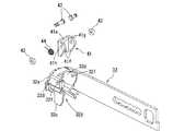
ファスナー供給装置20は、連結ネジ50を順次打ち込み位置に送るネジ送り機構を備えたものであり、図3等に示すように、工具本体11の先端に固定されるベース部21と、ベース部21の先端に摺動可能に設けられたノーズ部材30と、ベース部21に対してノーズ部材30を突出方向に付勢するバネ40と、を備えている。 The
ベース部21は、工具本体11の先端に取り付けられる部位である。このベース部21は、図3に示すように、角筒状のベースケーシング22と、ベースケーシング22の内側部に固定された板状のガイド部材24と、ベースケーシング22の下部に固定されて連結ネジ50を案内するためのマガジン23と、を有している。 The
一方、ノーズ部材30は、図3に示すように、ベースケーシング22の内部に沿って摺動可能な基部31と、基部31の先端方向に突出形成された先端アーム32と、を備えている。 On the other hand, as shown in FIG. 3, the
基部31の先端には、図1及び図3に示すように、上下に連通した保持溝31aが形成されている。この保持溝31aは、連結ネジ50の連結帯52を通すためのものであり、連結ネジ50を送ったときに送られた連結ネジ50の連結帯52が保持溝31aの下部開口から導入されて上部開口から抜けていくように形成されている。また、この保持溝31aの前後にはスリット31bが形成されており、後方のスリット31bからドライバビットが保持溝31aの内部へ入り込んで保持溝31aに保持されたネジ51を押し出すとともに、押し出されたネジ51が前方のスリット31bから打ち出されるようになっている。 As shown in FIGS. 1 and 3, a holding
また、先端アーム32は、基部31の先端に固定された平面視略L字形の部材であり、先端にコンタクト部32aを備えている。このコンタクト部32aは、ノーズ部材30を被打込み材に押し付けたときに被打込み材に当接する部分である。本実施形態に係るコンタクト部32aには、ネジ送り機構によって送られたネジ51の先端を受ける形状が形成されるとともに、ネジ51を打ち込み案内する射出口32bが開口形成されている。 The
本実施形態に係る連結ネジ用ネジ締め機10でネジ51を打ち込む際には、トリガ13を引いた状態でノーズ部材30(コンタクト部32a)を被打込み材に押し付ける。この操作により、ノーズ部材30がベース部21の内部へと押し込まれ、この動作に連動して、連結ネジ50の送り動作と、連結ネジ50の打ち込み動作とが実行される。 When the
ネジ51の送り動作は、図3に示すようなネジ送り機構によって実行される。このネジ送り機構は、図3に示すように、基部31に回転可能に軸支されたホイール部材33、ホイール部材33に回転力を伝達するためのワンウェイクラッチ機構(図示せず)、ワンウェイクラッチ機構に接続されたローラアーム37、ローラアーム37の先端に回転可能に支持されるローラ38、などで構成される。 The feeding operation of the
このうち、ホイール部材33は、ノーズ部材30の内部に回転可能に軸支される1対の部材である。このホイール部材33の外周縁には、連結ネジ50の連結帯52のノッチ52aと係合する歯が、ノッチ52aと等間隔で形成されている。ホイール部材33は、図3に示すように、ノッチ52aと係合する位置に配置され、送り方向(図5では時計回り)に回転することで、連結ネジ50を上方向へと送るように形成されている。 Among these members, the
ワンウェイクラッチは、ホイール部材33を送り方向にのみ回転させるために設けられた機構である。ローラアーム37が送り方向に動いたときには、この力をホイール部材33に伝達し、ローラアーム37が反送り方向に動いたときには、この力をホイール部材33に伝達しないように形成されている。 The one-way clutch is a mechanism provided to rotate the
ローラ38は、ノーズ部材30が押し込まれて摺動したときに、前述したガイド部材24によって移動をガイドされる。すなわち、図3に示すように、ガイド部材24は、ローラ38と略同じ幅で貫通形成された溝であるガイド部24aを備えており、ローラ38がこのガイド部24aに沿って移動をガイドされるように形成されている。ガイド部24aはノーズ部材30の押し込み方向に対して斜めに傾斜しているため、ローラ38がガイド部24aに沿って移動するとローラアーム37が揺動するようになっている。ローラアーム37が揺動することで回転力が生まれ、この回転力を利用してネジ送り動作が実行される。具体的には、ノーズ部材30が押し込まれたときには、ローラアーム37が送り方向に揺動するため、発生した回転力がワンウェイクラッチによってホイール部材33に伝達される。これにより、ホイール部材33が送り方向に回転し、連結ネジ50を1本ずつ送る。 The
そして、打ち込み動作が完了してノーズ部材30が被打ち込み材から離れると、バネ40の付勢力でノーズ部材30が待機位置へと戻る。これに連動して、ローラ38はガイド部24aのガイド部24aに沿って送り動作前の位置まで戻る。このとき、ローラアーム37が揺動するが、この動作はワンウェイクラッチの作用によって伝達されず、ホイール部材33の回転に影響を与えないようになっている。 Then, when the driving operation is completed and the
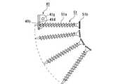
本実施形態においては、図4に示すように、先端アーム32の先端に受部32cが形成されており、この受部32cで送られたネジ51を受けることができるようになっている。受部32cは、両側に側壁部32dを設けることによって、ネジ51の先端が通過可能な通路32eを形成したものである。そして、側壁部32dには、垂直ガイド部材41が揺動可能に軸支されており、この垂直ガイド部材41によって送られてきたネジ51の先端付近を受けるように形成されている。 In the present embodiment, as shown in FIG. 4, a receiving
垂直ガイド部材41は、ネジ送り機構によって送られた先頭ネジ51を垂直にガイドするためのガイド構造を構成している。この垂直ガイド部材41は、図7に示すように、平面視略コ字形の金属製部材であり、中央のガイド板部41aと、ガイド板部41aの両側縁から垂直に延設される側板部41fと、を備える。 The
ガイド板部41aには、ネジ51の進入方向に開口した略U字形のガイド溝41bが形成されている。このガイド溝41bは、ネジ51の軸部51aをガイドするためのものであり、略U字形以外であっても、略V字形、略コ字形などでも良く、凹部形状によって少なくとも2点以上でのガイドが可能であればよい。なお、ガイド溝41bの開口部41cは、ネジ51を入り込み易くするために拡開して幅広に形成されている。また、ガイド溝41bの奥部41dは、テーパ状に傾斜している(詳細は後述する)。また、ガイド溝41bの側部41eの間隔は、ネジ51を両側から支持するために、ネジ51の軸部51aと略同じ幅となるように形成されている。 The
また、両側の側板部41fには、それぞれ軸孔41gが貫通形成されている。この軸孔41gは、垂直ガイド部材41を揺動可能に軸支するための一対の揺動軸42を貫通させるためのものである。一対の揺動軸42は、図4〜6に示すように、同軸上に配置されてそれぞれ軸孔41gを貫通し、受部32cの側壁部32dそれぞれに貫通形成された支持孔32fをも貫通するように取り付けられる。なお、揺動軸42の先端には抜け止め用のリング部材43が取り付けられる。 Further,
このように分割した2本の揺動軸42を使用することで、揺動軸42の間にネジ51の頭部51bを通過させるための空間が形成されている。このように揺動軸42の間をネジ51が通過可能とすることで、揺動軸42とネジ51(ガイド溝41b)とを近づけることができるので、垂直ガイド部材41の全長及び回転円弧を小さくすることができ、機械の全長を短くすることができるようになっている。 By using the two
このように取り付けられた垂直ガイド部材41は、捩りバネ44によって初期位置にて待機するように付勢されている。具体的には、垂直ガイド部材41の側部に切欠き形成されたバネ係合部41hに捩りバネ44を係合させることで、ガイド板部41aがネジ51の打ち込み方向に対して略直角となる位置で待機するように付勢される。この初期位置にてネジ送り機構によって先頭ネジ51が送られると、図8に示すように、該先頭ネジ51の軸部51aの先端付近がガイド溝41bに嵌入する。 The
また、先端アーム32は、基部31に対しする取付位置の調整が可能であるように構成されているので、使用する連結ネジ50のネジ長さが変化した場合であっても、送られたネジ51の先端部付近を確実に垂直ガイド部材41によってガイドすることが可能である。 In addition, since the
そして、ネジ送り動作後にネジ51が打ち込まれると、ネジ51は軸部51aを垂直ガイド部材41にガイドされたそのままの姿勢で垂直に打ち込まれる。そして、ネジ51の頭部51bが垂直ガイド部材41に当たると、図9に示すように、垂直ガイド部材41が捩りバネ44の付勢力に抗して退避方向に揺動し、ネジ51の頭部51bが通過するようになっている。このため、ネジ51が送られた直後から、ネジ51の頭部51bが通過する直前まで、ネジ51は垂直ガイド部材41によって同じ姿勢で垂直にガイドされるようになっている。 When the
ところで、本実施形態に係るガイド構造は、上述したように、ガイド溝41bの奥部41dをテーパ状に傾斜させているため、この傾斜に沿ってネジ51を滑らせて引き抜くことができる。具体的には、図10に示すように、連結ネジ50を上方に引き抜くと、ネジ51の先端が傾斜した垂直ガイド部材41の奥部41dに当たり、倒れる方向に誘導される。また、垂直ガイド部材41に対しても揺動する方向に力が加わるため、垂直ガイド部材41が退避方向に揺動する。このように、垂直ガイド部材41の奥部41dを傾斜させたことで、スムーズにネジ51を連結ネジ用ネジ締め機10から外すことができるようになっている。 By the way, as mentioned above, since the
なお、本実施形態では、図11に示すように、ガイド板部41aの表面と、ガイド溝41bの奥部41d及び軸孔41gを通過する面とがなす角度θ1が45度以下となるように設定されている。このような角度に設定することで、ネジ51を垂直に保つことができるとともに、ネジ51の頭部51bが通過するときに揺動し易くなっている。すなわち、この角度を大きくし過ぎると(例えば、図11のθ2が示すように45度以上に設定すると)、ネジ51が送られてきたときにD2の方向に加わる力で揺動し易く、ネジ51の頭部51bが通過するときにD1の方向に加わる力で揺動しにくくなってしまう。一方、本実施形態のように角度を小さく設定することで、ネジ51が送られてきたときにD2の方向に力が加わっても揺動せずにネジ51を垂直に支持でき、ネジ51の頭部51bが通過するときにD1の方向に力が加わったときには小さい力でも揺動するようにすることができる。 In the present embodiment, as shown in FIG. 11, the angle θ1 formed by the surface of the
また、ガイド溝41bは略U字形に形成されているので、送られてきたネジ51の軸部51aが接触するのは奥部41dであるが、ネジ51の頭部51bが通過するときは、ガイド溝41bの側部41eが頭部51bと接触する。それぞれ、揺動軸42との距離の違いにより、ネジ51が送られてガイド溝41bに力が加わった場合よりも、ネジ頭部51bが通過するときにガイド溝41bの側部41eに力が加わったときの方が、小さい力で垂直ガイド部材41が揺動するようにすることができる。 Further, since the
以上説明したように、本実施形態によれば、垂直ガイド部材41はネジ51の軸部51aをガイドする略U字形のガイド溝41bを備え、ネジ送り機構によって先頭ネジ51が送られたときに、該先頭ネジ51の軸部51aが前記ガイド溝41bに嵌入するとともに、前記ガイド溝41bに嵌入した先頭ネジ51が打ち込まれて該先頭ネジ51の頭部51bが通過するときに、前記垂直ガイド部材41が退避方向に揺動する。すなわち、送られてきたネジ51を略U字形のガイド溝41bによって受けてネジ51の姿勢をガイドしているので、打ち込み前のネジ51の姿勢をガイドすることができる。このため、打ち込み前において既にネジ51が垂直にガイドされているので、連結ネジ50がイナーシャで送られ過ぎることを防止してネジ51を垂直にガイドすることができる。そして、打ち込み動作中もネジ51は垂直にガイドされ続けるので、最後まで良好な垂直性を保つことができる。そして、ネジ51の頭部51bが通過する際には垂直ガイド部材41が退避方向に揺動するので、ネジ51の頭部51bも問題なく通過させることができる。 As described above, according to the present embodiment, the
また、片持ち形状の垂直ガイド部材41によってネジ51の姿勢をガイドしているため、垂直ガイドをボックス形状とする必要がない。このため、機構の内部が視認し易く、また、内部に手も入れやすいので、ネジ51が詰まったときの除ネジ作業も容易である。また、垂直ガイドがボックス形状でないため、機械先端を小さくすることができ、ネジ施工時の狙いを付けやすい機械とすることができる。 Further, since the posture of the
また、垂直ガイド部材41でネジ51の軸部51aを受けることができるので、ネジ51の先に垂直ガイド部材41を設けるための長さが必要ない。よって、ノーズ部材30を短くすることができ、機械の全長を短くすることができる。
また、構造も簡単であるため、プレス加工などで安価に部材を製造することができる。Further, since the
In addition, since the structure is simple, the member can be manufactured at low cost by pressing or the like.
また、前記ガイド溝41bの奥部41dをテーパ状に傾斜させたので、機械からネジ51を外す際、テーパ状に傾斜した奥部41dに沿ってネジ51を引き抜くことができ、また、この操作によって垂直ガイド部材41が揺動するので、容易にネジ51を外すことができる。 Further, since the
また、前記垂直ガイド部材41を同軸上に配置された一対の揺動軸42によって軸支することで、前記一対の揺動軸42の間をネジ51が通過可能に形成したので、垂直ガイド部材41の回転円弧を小さくすることができ、機械の全長を更に短くすることができる。 Further, since the
10 連結ネジ用ネジ締め機
11 工具本体
13 トリガ
14 バッテリ
20 ファスナー供給装置
21 ベース部
22 ベースケーシング
23 マガジン
24 ガイド部材
24a ガイド部
30 ノーズ部材
31 基部
31a 保持溝
31b スリット
32 先端アーム
32a コンタクト部
32b 射出口
32c 受部
32d 側壁部
32e 通路
32f 支持孔
33 ホイール部材
37 ローラアーム
38 ローラ
40 バネ
41 垂直ガイド部材
41a ガイド板部
41b ガイド溝
41c 開口部
41d 奥部
41e 側部
41f 側板部
41g 軸孔
41h バネ係合部
42 揺動軸
43 リング部材
44 捩りバネ
50 連結ネジ
51 ネジ
51a 軸部
51b 頭部
52 連結帯
52a ノッチDESCRIPTION OF
Claims (3)
Translated fromJapaneseベース部と、
前記ベース部の先端に摺動可能に設けられたノーズ部材と、
前記ネジ送り機構によって送られた先頭ネジを垂直にガイドするために前記ノーズ部材に退避可能に支持される垂直ガイド部材と、
を備え、
前記垂直ガイド部材は、ネジの先端付近をガイドする略U字形のガイド溝を備えるとともに、前記ネジ送り機構によって送られるネジの送り方向、及びネジの打込み方向に対して垂直方向に配置された揺動軸によって片持ち形状で揺動可能に軸支され、
前記ガイド溝よりも先端側に、ネジを打ち込み案内する射出口を開口形成し、
前記ネジ送り機構によって先頭ネジが送られたときに、該先頭ネジの軸部が前記ガイド溝に嵌入するとともに、前記ガイド溝に嵌入した先頭ネジが打ち込まれて該先頭ネジの頭部が通過するときに、前記垂直ガイド部材が退避することを特徴とする、連結ネジ用ネジ締め機におけるネジガイド構造。A guide structure in a screw feeding mechanism of a screw tightening machine for a connecting screw that sequentially sends a connecting screw in which a plurality of screws are connected by a connecting band to a driving position,
A base part;
A nose member slidably provided at the tip of the base portion;
A vertical guide member removably supported by the nose member for vertically guiding the leading screw sent by the screw feeding mechanism;
With
It said vertical guidememberRutotomoni comprises a generally U-shaped guide groove for guiding thevicinity of the tip of thescrew, arranged in a direction perpendicular to the feed direction, and driving direction of the screw of the screw to be sent by the screw feed mechanism It is pivotally supported in a cantilever shape by a swing shaft
An opening is formed on the tip side of the guide groove to drive and guide a screw,
When the head screw is fed by the screw feeding mechanism, the shaft portion of the head screw is fitted into the guide groove, and the head screw fitted into the guide groove is driven to pass through the head of the head screw. A screw guide structure in a screw tightening machine for connecting screws, wherein the vertical guide member is sometimes retracted.
Priority Applications (5)
| Application Number | Priority Date | Filing Date | Title |
|---|---|---|---|
| JP2013075727AJP6075164B2 (en) | 2013-04-01 | 2013-04-01 | Screw guide structure in screw tightening machine for connecting screw |
| CN201410128492.2ACN104097173B (en) | 2013-04-01 | 2014-04-01 | Screw guide formation in attachment screw nut runner |
| TW103112093ATWI581915B (en) | 2013-04-01 | 2014-04-01 | Screw guide structure of screw driver for collated screws |
| EP20140001215EP2786842A1 (en) | 2013-04-01 | 2014-04-01 | Screw guide structure of screw driver for collated screws |
| AU2014201862AAU2014201862A1 (en) | 2013-04-01 | 2014-04-01 | Screw guide structure of screw driver for collated screws |
Applications Claiming Priority (1)
| Application Number | Priority Date | Filing Date | Title |
|---|---|---|---|
| JP2013075727AJP6075164B2 (en) | 2013-04-01 | 2013-04-01 | Screw guide structure in screw tightening machine for connecting screw |
Publications (2)
| Publication Number | Publication Date |
|---|---|
| JP2014200850A JP2014200850A (en) | 2014-10-27 |
| JP6075164B2true JP6075164B2 (en) | 2017-02-08 |
Family
ID=50433917
Family Applications (1)
| Application Number | Title | Priority Date | Filing Date |
|---|---|---|---|
| JP2013075727AActiveJP6075164B2 (en) | 2013-04-01 | 2013-04-01 | Screw guide structure in screw tightening machine for connecting screw |
Country Status (5)
| Country | Link |
|---|---|
| EP (1) | EP2786842A1 (en) |
| JP (1) | JP6075164B2 (en) |
| CN (1) | CN104097173B (en) |
| AU (1) | AU2014201862A1 (en) |
| TW (1) | TWI581915B (en) |
Families Citing this family (1)
| Publication number | Priority date | Publication date | Assignee | Title |
|---|---|---|---|---|
| US11273541B2 (en)* | 2019-03-18 | 2022-03-15 | Kyocera Senco Industrial Tools, Inc. | Autofeed screwdriver attachment with twist collar to activate movable plates for latching to screw gun |
Family Cites Families (28)
| Publication number | Priority date | Publication date | Assignee | Title |
|---|---|---|---|---|
| JPS6045668U (en)* | 1983-09-05 | 1985-03-30 | 株式会社ケンウッド | Screw supply device for automatic screw tightening machine |
| JPS63167107A (en)* | 1986-12-29 | 1988-07-11 | 松下電器産業株式会社 | Screw tightening method |
| ATE190890T1 (en)* | 1991-11-20 | 2000-04-15 | Henrob Ltd | SETTING TOOLS AND ADHESIVE TAPE THEREOF |
| DE4201143A1 (en)* | 1992-01-17 | 1993-07-22 | Imt Ingenieurgemeinschaft Fuer | Screw guide for powered screwdriver - has geometry of lever holding screw on guide block chosen so that friction of screw applies moment forcing lever hard onto screw |
| JP3295572B2 (en)* | 1995-02-20 | 2002-06-24 | 株式会社マキタ | Continuous screw tightening machine |
| EP1022096B1 (en)* | 1995-11-20 | 2006-08-02 | Max Co., Ltd. | A screw guide mechanism of a screw driving and turning machine |
| JPH09285972A (en)* | 1996-04-18 | 1997-11-04 | Hitachi Koki Co Ltd | Screw tightening tool |
| JP3284531B2 (en)* | 1996-06-21 | 2002-05-20 | マックス株式会社 | Screw guide device for screw tightening machine for connecting screws |
| DE19731949C2 (en)* | 1996-07-26 | 2001-04-26 | Makita Corp | Screw conveyor in a continuously working screwdriver tool |
| JP3333114B2 (en)* | 1997-06-30 | 2002-10-07 | 株式会社ムロコーポレーション | Continuous screw tightening machine |
| JPH1170478A (en)* | 1997-08-29 | 1999-03-16 | Nippon Power Fuasuningu Kk | Screw feed structure of screw feeder |
| EP1319474A1 (en)* | 2001-12-17 | 2003-06-18 | Super Power Screw Co. Ltd | Screw driving gun having a slider member provided with a screw guiding spring |
| US6676001B1 (en)* | 2003-03-20 | 2004-01-13 | Diing-Shen Chen | Screw positioning device for a screw driving gun |
| JP2004298974A (en)* | 2003-03-28 | 2004-10-28 | Japan Power Fastening Co Ltd | Continuous fastener driving device |
| GB2401079B (en)* | 2003-04-30 | 2005-04-27 | Black & Decker Inc | Screw feeder |
| US7032482B1 (en)* | 2003-10-31 | 2006-04-25 | Senco Products, Inc. | Tensioning device apparatus for a bottom feed screw driving tool for use with collated screws |
| JP4434069B2 (en)* | 2005-04-28 | 2010-03-17 | 日立工機株式会社 | Connecting screw driver |
| TWM305092U (en)* | 2006-07-10 | 2007-01-21 | Jiun-Shiou Shiu | Device of screwing gun for guiding and fixing screw |
| JP4871708B2 (en)* | 2006-11-13 | 2012-02-08 | 株式会社マキタ | Screw feeder for continuous screw tightening machine |
| JP4891061B2 (en)* | 2006-12-28 | 2012-03-07 | 株式会社マキタ | Screw feeder of screw tightening machine |
| TW200927394A (en)* | 2007-12-25 | 2009-07-01 | Basso Ind Corp | Adjustable feeding apparatus for screw gun |
| TW200938739A (en)* | 2008-03-07 | 2009-09-16 | Basso Ind Corp | Screw nail retaining structure and nail feeder using the same |
| TW200950936A (en)* | 2008-06-02 | 2009-12-16 | Basso Ind Corp | Adjustable nail supply device of screw nail gun |
| TW201010829A (en)* | 2008-09-08 | 2010-03-16 | Mobiletron Electronics Co Ltd | Automatic screw feeding apparatus for electricity powered screwdriver |
| TWI345515B (en)* | 2009-01-22 | 2011-07-21 | Basso Ind Corp | A screw guiding structure of a screwdriver and method |
| US8544369B2 (en)* | 2010-06-30 | 2013-10-01 | Simpson Strong-Tie Company, Inc. | Autofeed screwdriving tool |
| TWM412845U (en)* | 2011-01-04 | 2011-10-01 | De Poan Pneumatic Corp | Nail-poking device for screw gun |
| TWM408465U (en)* | 2011-03-08 | 2011-08-01 | De Poan Pneumatic Corp | Nail feeding regulation device for screw nail gun |
- 2013
- 2013-04-01JPJP2013075727Apatent/JP6075164B2/enactiveActive
- 2014
- 2014-04-01CNCN201410128492.2Apatent/CN104097173B/enactiveActive
- 2014-04-01AUAU2014201862Apatent/AU2014201862A1/ennot_activeAbandoned
- 2014-04-01EPEP20140001215patent/EP2786842A1/ennot_activeWithdrawn
- 2014-04-01TWTW103112093Apatent/TWI581915B/enactive
Also Published As
| Publication number | Publication date |
|---|---|
| TWI581915B (en) | 2017-05-11 |
| AU2014201862A1 (en) | 2014-10-16 |
| CN104097173A (en) | 2014-10-15 |
| TW201509605A (en) | 2015-03-16 |
| CN104097173B (en) | 2017-06-27 |
| JP2014200850A (en) | 2014-10-27 |
| EP2786842A1 (en) | 2014-10-08 |
Similar Documents
| Publication | Publication Date | Title |
|---|---|---|
| JP5813183B1 (en) | Screw supply mechanism of screw feeder | |
| EP3479942B1 (en) | Cutting tool | |
| JPH0679639A (en) | Device for feeding mounting means particularly driving tool for supplying screw | |
| JP6075164B2 (en) | Screw guide structure in screw tightening machine for connecting screw | |
| JP6127662B2 (en) | Screw feeding mechanism of connecting screw screw tightening machine and connecting screw screw tightening machine | |
| KR101654536B1 (en) | Transfer and insertion device for a pcb terminals | |
| JP6608867B2 (en) | Screw member take-out mechanism of screw member supply device | |
| JP5219704B2 (en) | Chip dresser device | |
| JP4442725B2 (en) | Screw feeder | |
| CN110479913B (en) | Feeding and cutting device | |
| KR200329195Y1 (en) | A cutting device of pipe | |
| JP5741120B2 (en) | Portable cutting machine | |
| JP6038692B2 (en) | Pachinko machine mounting device | |
| JP2903512B2 (en) | Screw guide device for screw tightening machine for connecting screws | |
| TW201607648A (en) | Tool storage apparatus | |
| JP2011104818A (en) | Portable cutting machine | |
| JP4378759B2 (en) | Punching tool and its contact portion forming body | |
| US1103785A (en) | Automatic stop for drills. | |
| JP3796563B2 (en) | Drilling tool | |
| JP2016155668A (en) | Position adjustment device for belt tension adjustment bracket | |
| JP4143052B2 (en) | Screw feeder | |
| US20100065600A1 (en) | Auto-breaking machine | |
| US20110033256A1 (en) | Annular Sawing Structure | |
| JP3451575B2 (en) | Electric canna | |
| JP2007253250A (en) | Hook device of hammering tool |
Legal Events
| Date | Code | Title | Description |
|---|---|---|---|
| A621 | Written request for application examination | Free format text:JAPANESE INTERMEDIATE CODE: A621 Effective date:20151216 | |
| A977 | Report on retrieval | Free format text:JAPANESE INTERMEDIATE CODE: A971007 Effective date:20160907 | |
| A131 | Notification of reasons for refusal | Free format text:JAPANESE INTERMEDIATE CODE: A131 Effective date:20160913 | |
| A521 | Written amendment | Free format text:JAPANESE INTERMEDIATE CODE: A523 Effective date:20161114 | |
| TRDD | Decision of grant or rejection written | ||
| A01 | Written decision to grant a patent or to grant a registration (utility model) | Free format text:JAPANESE INTERMEDIATE CODE: A01 Effective date:20161213 | |
| A61 | First payment of annual fees (during grant procedure) | Free format text:JAPANESE INTERMEDIATE CODE: A61 Effective date:20161226 | |
| R150 | Certificate of patent or registration of utility model | Ref document number:6075164 Country of ref document:JP Free format text:JAPANESE INTERMEDIATE CODE: R150 |