JP6072027B2 - Surgical instrument for patella clamp and drill guided surgery - Google Patents
Surgical instrument for patella clamp and drill guided surgeryDownload PDFInfo
- Publication number
- JP6072027B2 JP6072027B2JP2014519144AJP2014519144AJP6072027B2JP 6072027 B2JP6072027 B2JP 6072027B2JP 2014519144 AJP2014519144 AJP 2014519144AJP 2014519144 AJP2014519144 AJP 2014519144AJP 6072027 B2JP6072027 B2JP 6072027B2
- Authority
- JP
- Japan
- Prior art keywords
- plate
- drill
- surgical instrument
- bracket
- orthopedic surgical
- Prior art date
- Legal status (The legal status is an assumption and is not a legal conclusion. Google has not performed a legal analysis and makes no representation as to the accuracy of the status listed.)
- Active
Links
- 210000004417patellaAnatomy0.000titleclaimsdescription70
- 238000001356surgical procedureMethods0.000titleclaimsdescription8
- 230000000399orthopedic effectEffects0.000claimsdescription62
- 238000005530etchingMethods0.000claimsdescription14
- 239000012780transparent materialSubstances0.000claimsdescription7
- 239000002184metalSubstances0.000claimsdescription6
- 239000002861polymer materialSubstances0.000claimsdescription3
- 239000013536elastomeric materialSubstances0.000claimsdescription2
- 230000006835compressionEffects0.000description6
- 238000007906compressionMethods0.000description6
- 239000000463materialSubstances0.000description5
- 229920000642polymerPolymers0.000description5
- 210000003127kneeAnatomy0.000description4
- 238000007493shaping processMethods0.000description4
- 230000008901benefitEffects0.000description3
- 229920001971elastomerPolymers0.000description3
- 238000000034methodMethods0.000description3
- 238000012986modificationMethods0.000description3
- 230000004048modificationEffects0.000description3
- BAPJBEWLBFYGME-UHFFFAOYSA-NMethyl acrylateChemical compoundCOC(=O)C=CBAPJBEWLBFYGME-UHFFFAOYSA-N0.000description2
- 239000000806elastomerSubstances0.000description2
- 238000002513implantationMethods0.000description2
- 239000007769metal materialSubstances0.000description2
- -1polyethylenePolymers0.000description2
- 229910001220stainless steelInorganic materials0.000description2
- 239000010935stainless steelSubstances0.000description2
- 239000004698PolyethyleneSubstances0.000description1
- 210000003484anatomyAnatomy0.000description1
- 238000011882arthroplastyMethods0.000description1
- 239000007767bonding agentSubstances0.000description1
- 238000005553drillingMethods0.000description1
- 239000011521glassSubstances0.000description1
- 239000007943implantSubstances0.000description1
- 238000003801millingMethods0.000description1
- 238000010422paintingMethods0.000description1
- 229920000058polyacrylatePolymers0.000description1
- 239000004417polycarbonateSubstances0.000description1
- 229920000515polycarbonatePolymers0.000description1
- 229920000573polyethylenePolymers0.000description1
- 238000006116polymerization reactionMethods0.000description1
- 230000000087stabilizing effectEffects0.000description1
- 210000000689upper legAnatomy0.000description1
Images


Classifications
- A—HUMAN NECESSITIES
- A61—MEDICAL OR VETERINARY SCIENCE; HYGIENE
- A61B—DIAGNOSIS; SURGERY; IDENTIFICATION
- A61B17/00—Surgical instruments, devices or methods
- A61B17/16—Instruments for performing osteoclasis; Drills or chisels for bones; Trepans
- A61B17/17—Guides or aligning means for drills, mills, pins or wires
- A61B17/1739—Guides or aligning means for drills, mills, pins or wires specially adapted for particular parts of the body
- A61B17/1764—Guides or aligning means for drills, mills, pins or wires specially adapted for particular parts of the body for the knee
- A61B17/1767—Guides or aligning means for drills, mills, pins or wires specially adapted for particular parts of the body for the knee for the patella
- A—HUMAN NECESSITIES
- A61—MEDICAL OR VETERINARY SCIENCE; HYGIENE
- A61F—FILTERS IMPLANTABLE INTO BLOOD VESSELS; PROSTHESES; DEVICES PROVIDING PATENCY TO, OR PREVENTING COLLAPSING OF, TUBULAR STRUCTURES OF THE BODY, e.g. STENTS; ORTHOPAEDIC, NURSING OR CONTRACEPTIVE DEVICES; FOMENTATION; TREATMENT OR PROTECTION OF EYES OR EARS; BANDAGES, DRESSINGS OR ABSORBENT PADS; FIRST-AID KITS
- A61F2/00—Filters implantable into blood vessels; Prostheses, i.e. artificial substitutes or replacements for parts of the body; Appliances for connecting them with the body; Devices providing patency to, or preventing collapsing of, tubular structures of the body, e.g. stents
- A61F2/02—Prostheses implantable into the body
- A61F2/30—Joints
- A61F2/38—Joints for elbows or knees
- A61F2/3877—Patellae or trochleae
Landscapes
- Health & Medical Sciences (AREA)
- Surgery (AREA)
- Life Sciences & Earth Sciences (AREA)
- Biomedical Technology (AREA)
- Medical Informatics (AREA)
- Orthopedic Medicine & Surgery (AREA)
- Oral & Maxillofacial Surgery (AREA)
- Engineering & Computer Science (AREA)
- Dentistry (AREA)
- Heart & Thoracic Surgery (AREA)
- Nuclear Medicine, Radiotherapy & Molecular Imaging (AREA)
- Molecular Biology (AREA)
- Animal Behavior & Ethology (AREA)
- General Health & Medical Sciences (AREA)
- Public Health (AREA)
- Veterinary Medicine (AREA)
- Prostheses (AREA)
- Surgical Instruments (AREA)
Description
Translated fromJapanese (関連出願の相互参照)
本願は、2011年6月30日出願の「PATELLA CLAMP AND DRILL GUIDE SURGICAL INSTRUMENT」と題する米国仮出願第61/503.419号に対して35 U.S.C.§ 119の下で優先権を主張し、その全体が参照することにより本明細書に組み込まれる。(Cross-reference of related applications)
This application is based on US provisional application 61 / 503.419 entitled “PATELLA CLAMP AND DRILL GUIDE SURGICAL INSTRUMENT” filed June 30, 2011. S. C. § 119 claims priority and is hereby incorporated by reference in its entirety.
(関連米国出願の更なる相互参照)
Abraham Wrightらによる「PATELLA DRILL GUIDE AND CLAMP LY」と題する同時係属の米国仮特許出願第61/503.164号(代理人整理番号265280−214717、DEP9386USNP)、及びAbraham Wrightらによる「PATELLA DRILL GUIDE AND CLAMP」と題する同時係属の米国意匠特許出願第29/396.511号(代理人整理番号265280−215723、DEP6398USDP)に対して相互参照が行われ、それらのそれぞれは、本願と同一の出願人に譲渡され、本願と同時に出願され、参照することによって本明細書に組み込まれる。(Further cross-reference of related US applications)
Co-pending US Provisional Patent Application No. 61 / 503.164 (Attorney Docket No. 265280-214717, DEP9386USNP) entitled “PATELLA DRILL GUIDE AND CLAMP LY” by Abraham Wright et al. Cross-references are made to co-pending US
(発明の分野)
本開示は、概して、整形外科用手術器具に関し、より具体的には、膝蓋骨手術器具に関する。(Field of Invention)
The present disclosure relates generally to orthopedic surgical instruments, and more specifically to patella surgical instruments.
関節形成術は、病変及び/又は損傷した自然関節をプロテーゼ関節で置換する周知の外科手術である。典型的な膝プロテーゼは、脛骨トレー、大腿骨構成要素、及び脛骨トレーと大腿骨構成要素との間に配置されるポリマーインサート又はベアリングを含む。ある場合においては、人工膝関節は、人工膝蓋骨コンポーネントも含んでよく、このコンポーネントは、手術により準備された患者の膝蓋骨の後部側に固定される。人工装具コンポーネントを膝蓋骨に固定するために、整形外科医は、患者の天然膝蓋骨の後方側面を切除して、人工装具コンポーネントを受容するように、天然膝蓋骨を準備することができる。使用時、膝蓋骨人工装具コンポーネントは、患者の膝の伸展及び屈曲の間、患者の天然又は義足の大腿骨とともに関節接合をなす。 Arthroplasty is a well-known surgical procedure that replaces a lesioned and / or damaged natural joint with a prosthetic joint. A typical knee prosthesis includes a tibial tray, a femoral component, and a polymer insert or bearing disposed between the tibial tray and the femoral component. In some cases, the knee prosthesis may also include an artificial patella component, which is secured to the posterior side of the patient's patella prepared by surgery. To secure the prosthetic component to the patella, the orthopedic surgeon can prepare the natural patella to receive the prosthetic component by excising the posterior aspect of the patient's natural patella. In use, the patella prosthetic component articulates with the patient's natural or prosthetic femur during knee extension and flexion of the patient.
天然関節を人工膝関節で置き換えることを容易にするために、整形外科医は、例えば、切断ブロック、ドリル案内、ミリング案内、及び他の手術器具等の様々な整形外科用手術器具を使用する。 In order to facilitate the replacement of natural joints with knee prostheses, orthopedic surgeons use various orthopedic surgical instruments such as, for example, cutting blocks, drill guides, milling guides, and other surgical instruments.
本開示の一態様によれば、整形外科用手術器具が開示される。整形外科用手術器具は、第1のブラケットと、第1のブラケットに移動可能に連結される、第2のブラケットと、を有する、膝蓋骨ドリル案内と、第2のブラケットに取り外し可能に連結される、ガスケットと、を含む。第2のブラケットは、中に画定された複数の案内穴を有するドリルプレートを含み、ドリルプレートは、実質的に透明な材料から形成される。複数の案内穴のそれぞれは、手術用ドリルを受容するように寸法調整される。ガスケットは、第2のブラケットに連結されるとき、案内穴を被覆するように構成される。 According to one aspect of the present disclosure, an orthopedic surgical instrument is disclosed. An orthopedic surgical instrument has a first bracket and a second bracket movably coupled to the first bracket, and a patella drill guide and removably coupled to the second bracket. Including a gasket. The second bracket includes a drill plate having a plurality of guide holes defined therein, the drill plate being formed from a substantially transparent material. Each of the plurality of guide holes is sized to receive a surgical drill. The gasket is configured to cover the guide hole when coupled to the second bracket.
いくつかの実施形態では、第1のブラケットは、取付板を含んでもよい。取付板は、そこから延在する第1の複数の歯を有する第1の締め付け表面を有してもよい。第2のブラケットのドリルプレートは、取付板の第1の締め付け表面に面する第1の締め付け表面を含んでもよい。ドリルプレートの第1の締め付け表面は、そこから延在する第2の複数の歯を有してもよい。 In some embodiments, the first bracket may include a mounting plate. The mounting plate may have a first clamping surface having a first plurality of teeth extending therefrom. The drill plate of the second bracket may include a first clamping surface that faces the first clamping surface of the mounting plate. The first clamping surface of the drill plate may have a second plurality of teeth extending therefrom.
いくつかの実施形態では、取付板の第1の締め付け表面は、ドリルプレートの第1の締め付け表面に実質的に平行に延在してもよい。加えて、いくつかの実施形態では、ガスケットは、ドリルプレートの第1の締め付け表面と接触するように構成される、第1の表面を有してもよい。ガスケットの第1の表面は、ドリルプレートの第2の複数の歯を受容するように構成される、その中に画定された複数の位置決め穴を有してもよい。いくつかの実施形態では、ガスケットは、第1の表面の反対側の第2の凹部表面を有してもよい。 In some embodiments, the first clamping surface of the mounting plate may extend substantially parallel to the first clamping surface of the drill plate. In addition, in some embodiments, the gasket may have a first surface configured to contact a first clamping surface of the drill plate. The first surface of the gasket may have a plurality of positioning holes defined therein configured to receive the second plurality of teeth of the drill plate. In some embodiments, the gasket may have a second recessed surface opposite the first surface.
いくつかの実施形態では、ドリルプレートの第1の締め付け表面は、その中に画定された複数のエッチングマークを有してもよい。各エッチングマークは、患者の膝蓋骨の寸法に対応し得る。加えて、いくつかの実施形態では、複数のエッチングマークは、ドリルプレートの第1の締め付け表面に画定された複数の内接線として配置されてもよい。いくつかの実施形態では、ドリルプレートは、第1の締め付け表面の反対側に位置付けられた前面を有してもよい。各内接線は、前面を通して見えてもよい。 In some embodiments, the first clamping surface of the drill plate may have a plurality of etching marks defined therein. Each etching mark may correspond to the size of the patient's patella. In addition, in some embodiments, the plurality of etch marks may be arranged as a plurality of inscribed lines defined on the first clamping surface of the drill plate. In some embodiments, the drill plate may have a front surface positioned opposite the first clamping surface. Each inscribed line may be visible through the front surface.
いくつかの実施形態では、取付板及びドリルプレートは、高分子材料から形成されてもよい。いくつかの実施形態では、整形外科用手術器具は、ドリルプレートに取り付けられた複数の金属ブッシングを含んでもよい。各金属ブッシングは、複数の案内穴のうちの対応する1つを画定してもよい。 In some embodiments, the mounting plate and drill plate may be formed from a polymeric material. In some embodiments, the orthopedic surgical instrument may include a plurality of metal bushings attached to a drill plate. Each metal bushing may define a corresponding one of the plurality of guide holes.
更に、いくつかの実施形態では、ドリルプレートの複数の案内穴が三角形のパターンに配列されてもよい。いくつかの実施形態では、ガスケットは、エラストマー材から形成されてもよい。 Further, in some embodiments, the plurality of drill holes in the drill plate may be arranged in a triangular pattern. In some embodiments, the gasket may be formed from an elastomeric material.
本開示の別の態様によると、整形外科用手術器具は、ハンドルと第1のブラケットとを含む、ハウジングを有する。第1のブラケットは、取付板と、そこから延在する複数の歯と、を有する。整形外科用手術器具はまた、ハウジングに移動可能に連結される第2のブラケットを含む。第2のブラケットは、第1のブラケットの取付板から離間したドリルプレートを有し、ドリルプレートは、複数の案内穴を含む。案内穴のそれぞれは、手術用ドリルを受容するように寸法調整され、複数の歯が、ドリルプレートから取付板に向かって延在する。整形外科用手術器具は更に、ハウジング及び第2のブラケットに連結されるクランプ作動機構を含む。クランプ作動機構は、第1のブラケットに向かって第1の方向に第2のブラケットを移動させるように動作可能である。 According to another aspect of the present disclosure, an orthopedic surgical instrument has a housing that includes a handle and a first bracket. The first bracket has a mounting plate and a plurality of teeth extending therefrom. The orthopedic surgical instrument also includes a second bracket movably coupled to the housing. The second bracket has a drill plate spaced from the mounting plate of the first bracket, and the drill plate includes a plurality of guide holes. Each of the guide holes is sized to receive a surgical drill, and a plurality of teeth extend from the drill plate toward the mounting plate. The orthopedic surgical instrument further includes a clamp actuation mechanism coupled to the housing and the second bracket. The clamp actuation mechanism is operable to move the second bracket in a first direction toward the first bracket.
いくつかの実施形態では、複数の案内穴のそれぞれは、そこを通って延在する縦軸を有してもよい。第2のブラケットは、ハウジングに移動可能に連結されるビームを含んでもよい。ビームは、案内穴の縦軸に平行に延在する軸に沿って、ハウジングに対して移動するように構成されてもよい。加えて、いくつかの実施形態では、クランプ作動機構は、ハウジングに位置付けられ、ビームに係合するように構成される、作動プレートを含んでもよい。作動プレートは、フォロワ表面を含んでもよい。クランプ作動機構は、レバーが第1の位置と第2の位置との間で移動可能であるように、ハウジングに枢動可能に連結されるレバーを含んでもよい。第1の位置から第2の位置に移動するとき、作動プレートのフォロワ表面に係合するように構成される、カム表面をレバーが含み、作動プレートが、ビームに係合して、第1の方向の軸に沿って第2のブラケットを移動させる。 In some embodiments, each of the plurality of guide holes may have a longitudinal axis extending therethrough. The second bracket may include a beam movably coupled to the housing. The beam may be configured to move relative to the housing along an axis extending parallel to the longitudinal axis of the guide hole. In addition, in some embodiments, the clamp actuation mechanism may include an actuation plate positioned on the housing and configured to engage the beam. The actuation plate may include a follower surface. The clamp actuation mechanism may include a lever that is pivotally coupled to the housing such that the lever is movable between a first position and a second position. The lever includes a cam surface configured to engage the follower surface of the actuating plate when moving from the first position to the second position, the actuating plate engaging the beam, The second bracket is moved along the direction axis.
いくつかの実施形態では、クランプ作動機構は、作動プレートとハウジングの内壁との間に位置付けられた、付勢要素を含んでもよい。 In some embodiments, the clamp actuation mechanism may include a biasing element positioned between the actuation plate and the inner wall of the housing.
加えて、いくつかの実施形態では、整形外科用手術器具は更に、第1のブラケットから離れた第2の方向への第2のブラケットの運動を選択的に阻止するように構成される、ロック機構を含んでもよい。いくつかの実施形態では、ロック機構は、ロックプレートが第2のブラケットの第2の方向への運動を阻止するようにビームに係合する、第1の位置と、第2のブラケットが第2の方向に移動できるようにロックプレートがビームから解放される、第2の位置と、の間で移動可能な、ロックプレートを含んでもよい。ロック機構は、ロックプレートとハウジングとの間に位置付けられた付勢要素を含んでもよい。付勢要素は、ロックプレートを第1の位置で付勢するように構成されてもよい。いくつかの実施形態では、整形外科用手術器具は、ロックプレートに取り付けられる解放ボタンを含んでもよい。 In addition, in some embodiments, the orthopedic surgical instrument is further configured to selectively prevent movement of the second bracket in a second direction away from the first bracket. A mechanism may be included. In some embodiments, the locking mechanism includes a first position in which the locking plate engages the beam such that the locking plate prevents movement of the second bracket in the second direction, and the second bracket is in the second position. A locking plate may be included that is movable between a second position in which the locking plate is released from the beam so that it can be moved in the direction of. The locking mechanism may include a biasing element positioned between the lock plate and the housing. The biasing element may be configured to bias the lock plate in the first position. In some embodiments, the orthopedic surgical instrument may include a release button attached to the lock plate.
別の態様によると、整形外科用手術器具は、ハンドルと第1のブラケットとを含む、ポリマーハウジングを有する。第1のブラケットは、取付板と、そこから延在する複数の歯と、を有してもよい。整形外科用手術器具はまた、ハウジングに移動可能に連結される第2のブラケットを含む。第2のブラケットは、実質的に透明な材料から形成されるドリルプレートを有する。ドリルプレートは、締め付け表面と、前面と、締め付け表面及び前面を通って延在する複数の案内穴と、を含む。案内穴のそれぞれは、手術用ドリルを受容するように寸法調整される。複数のエッチングマークが、ドリルプレートの締め付け表面に画定される。複数のエッチングマークは、前面を通して見える。整形外科用手術器具は更に、ポリマーハウジング及び第2のブラケットに連結されるクランプ作動機構と、ハウジング及び第2のブラケットに連結されるロック機構と、を含む。クランプ作動機構は、第1のブラケットに向かって第1の方向に第2のブラケットを移動させるように動作可能であり、ロック機構は、第1のブラケットから離れた第2の方向への第2のブラケットの運動を選択的に阻止するように構成される。 According to another aspect, an orthopedic surgical instrument has a polymer housing that includes a handle and a first bracket. The first bracket may have a mounting plate and a plurality of teeth extending therefrom. The orthopedic surgical instrument also includes a second bracket movably coupled to the housing. The second bracket has a drill plate formed from a substantially transparent material. The drill plate includes a clamping surface, a front surface, and a plurality of guide holes extending through the clamping surface and the front surface. Each of the guide holes is sized to receive a surgical drill. A plurality of etching marks are defined on the clamping surface of the drill plate. Multiple etching marks are visible through the front surface. The orthopedic surgical instrument further includes a clamp actuation mechanism coupled to the polymer housing and the second bracket, and a locking mechanism coupled to the housing and the second bracket. The clamp actuation mechanism is operable to move the second bracket in a first direction toward the first bracket, and the locking mechanism is second in a second direction away from the first bracket. Configured to selectively prevent movement of the bracket.
発明を実施するための形態においては特に以下の図面を参照する。
本開示の概念には様々な改変及び代替的形態が考えられるが、その特定の代表的な実施形態を図面に例として示し、本明細書において詳細に述べる。ただし、本開示の概念を開示される特定の形態に限定することを何ら意図するものではなく、その逆に、本発明は、添付の「特許請求の範囲」において定義される発明の趣旨及び範囲に包含されるすべての改変物、均等物及び代替物を網羅することを意図するものである点は理解されるべきである。 While various modifications and alternative forms of the concept of the present disclosure are possible, certain representative embodiments thereof are shown by way of example in the drawings and are described in detail herein. However, it is not intended to limit the concept of the present disclosure to the specific forms disclosed, but on the contrary, the present invention is intended to be within the spirit and scope of the invention as defined in the appended claims. It should be understood that it is intended to cover all modifications, equivalents, and alternatives encompassed by.
解剖学的参照を表す、前、後、内側、外側、上、下などの用語は、本明細書の全体を通じて、本明細書において述べられる整形外科用インプラント及び外科器具に関して、並びに患者の自然の解剖学的構造に関して使用され得る。これらの用語は、解剖学的構造の研究及び整形外科学の分野のいずれにおいても広く理解された意味を有するものである。明細書及び特許請求の範囲におけるこれらの解剖学的基準を表す用語の使用は、特に断らないかぎりは、それらの広く理解されている意味と一貫性を有するものとする。 The terms anatomical reference, such as front, back, medial, lateral, top, bottom, etc., refer to orthopedic implants and surgical instruments described herein throughout the present specification and to the patient's natural. Can be used for anatomical structures. These terms have a widely understood meaning both in the field of anatomical research and orthopedic surgery. The use of terms representing these anatomical criteria in the specification and claims shall be consistent with their well-understood meanings unless otherwise noted.
図1を参照すると、整形外科用手術器具10は、膝蓋骨クランプ及びドリル案内12(以下、案内12)と、案内12に固定されるように構成される、圧縮ガスケット14と、を含む。以下で更に詳述されるように、器具10を利用して、膝蓋骨人工コンポーネント、例えば、膝蓋骨人工コンポーネント18(図9を参照)の埋め込み用の患者の切除された膝蓋骨16(図9を参照)を外科的に準備する。そうするために、患者の切除された膝蓋骨16は、案内12に位置付けられてもよく、外科医は、案内12を使用して、平面の切除された後面に固定穴を穿孔してもよい。外科医はまた、案内12を使用して、患者の膝蓋骨で使用するために好適な膝蓋骨人工コンポーネントを寸法調整及び選択してもよい。膝蓋骨人工コンポーネントが選択された後、外科医は、案内12及びガスケット14を使用して、選択された膝蓋骨人工コンポーネントを患者の切除された膝蓋骨に固定してもよい。 With reference to FIG. 1, an orthopedic
図1に示されるように、器具10の案内12は、ハウジング20と、ハウジング20に対して移動するように構成される、締め付けブラケット22と、を含む。ハウジング20は、本体24と、本体24から下向きに延在するハンドル26と、を有する。ハンドル26は、外科医の手によって把持されるように寸法調整される、グリップ30を画定する複数のリブ28を含む。ハウジング20はまた、ハンドル26の反対側の本体24から延在する、支持ブラケット32を含む。支持ブラケット32は、患者の切除された膝蓋骨16の前側に係合するように構成される、取付板34を有する。 As shown in FIG. 1, the
案内12の締め付けブラケット22は、ビーム36と、ビーム36に取り付けられるドリルプレート38と、を含む。ビーム36は、ハウジング20の本体24に画定された通路40に受容され、ハウジング20に対して摺動するように構成される。案内12はまた、ハウジング20の本体24から下向きに延在するレバー又はトリガーアーム44を含む、クランプ作動機構42を有する。トリガーアーム44は、力が矢印46によって示されるように印加されるとき、ハウジング20に対して枢動するように構成される。トリガーアーム44を作動することによって、締め付けブラケット22のドリルプレート38は、以下で更に詳述されるように、支持ブラケット32の取付板34に向かって前進してもよい。 The clamping
締め付けブラケット22のビーム36は、ハウジング20の通路40から端部50に外向きに延在する。一対の取付アーム52、54は、ビーム36の端部50から上向きに延在し、ドリルプレート38が取付アーム52、54に固定される。例示の実施形態では、ドリルプレート38及びビーム36は別々に形成され、後に組み立てられる。他の実施形態では、ビーム36及びドリルプレート38が、単一のモノリシックコンポーネントとして成形又は別様に形成されてもよいことを理解されたい。 The
締め付けブラケット22のドリルプレート38は、取付板34に面する平面の締め付け表面56と、締め付け表面56と反対側の前面58と、表面56、58を接続する側壁60と、を有する。複数の歯62は、締め付け表面56から支持ブラケット32の取付板34に向かって延在し、各歯62は、患者の切除された膝蓋骨16に係合するように構成される、先端部64を含む。図1に示されるように、ドリルプレート38は、締め付け表面56上で三角形のパターンで配置される3つの歯62を含む。他の実施形態では、ドリルプレート38が、他の幾何学的パターンで配置される更なる歯又はより少ない歯を含んでもよいことが理解されるべきである。加えて、他の実施形態では、歯は、ドリルプレート38に取り外し可能に取り付けられてもよい。 The
ドリルプレート38はまた、表面56、58を通って延在する複数の円筒形開口部66も含む。開口部66は、三角形のパターンで配置される、各開口部66は、その中に位置付けられたブッシング68を有する。ドリルプレート38の案内穴70は、各ブッシング68を通って画定され、各案内穴70は、そこを通って延在する縦軸72を有する。以下で更に詳述されるように、各案内穴70は、手術用ドリル74(図11を参照)を受容し、ドリル74を軸72に沿って誘導し、患者の切除された膝蓋骨16と接触させるように寸法調整される。例示的な実施形態では、ドリルプレート38は、3つの案内穴70を有する。他の実施形態では、ドリルプレート38が、図1に示される三角形のパターン以外の幾何学的パターンで配置される、更なる又はより少ない案内穴70を含んでもよいことが理解されるべきである。 The
ドリルプレート38のブッシング68は、ステンレス鋼等の金属材料から形成される。他の実施形態では、ブッシング68は、耐摩耗性の高分子材料から形成されてもよい。また、他の実施形態では、ブッシング68が省かれてもよいことも理解されるべきである。 The
ハウジング20及び締め付けブラケット22のビーム36はそれぞれ、例えば、ポリエチレン等の高分子材料から形成される。他の実施形態では、ハウジング20及びビーム36は、ステンレス鋼等の金属材料から形成されてもよい。ドリルプレート38は、実質的に透明な材料から形成される。例示的な実施形態では、ドリルプレート38は、例えば、ポリカーボネート等のアクリレートポリマーから形成される。また、ドリルプレート38が、例えば、メチルアクリレート又はガラス等の他の実質的に透明な材料から形成されてもよいことが理解されるべきである。 The
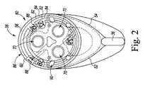
ここで図2及び3を参照すると、締め付けブラケット22のドリルプレート38は、患者の膝蓋骨の複数の寸法に対応する、複数のインジケータ80を含む。インジケータ80は、締め付け表面56に画定された複数のエッチングマーク82を含み、それらのそれぞれは、患者の膝蓋骨の異なる寸法に対応する。図2に示されるように、エッチングマーク82は、狭い、及び中間の寸法を示す多くの内接線84として配置される。インジケータ80はまた、ドリルプレート38の側壁60の外周86も含み、それは、インジケータ80によって示される膝蓋骨寸法のうちの最大幅の膝蓋骨寸法を示す。他の実施形態では、ドリルプレート38はより大きくてもよく、患者の膝蓋骨の他の考えられる寸法に対応する、追加のインジケータ80を含んでもよい。 2 and 3, the
インジケータ80のそれぞれは、対応する数字記号88によって識別され、それは、特定の膝蓋骨寸法に対応する。インジケータ80が図2に示されるような見方をすると、数字記号88は逆又は反射して見える。図3に示されるような見方をすると、ドリルプレート38が実質的に透明であるため、エッチングマーク82及び数字記号88は、適切に配向され、前面58を通して見ることができる。同様に、患者の切除された膝蓋骨がドリルプレート38と取付板34との間に位置付けられたとき、膝蓋骨もまた、前面58を通して見ることができる。他の実施形態では、線及びインジケータが、エッチングよりもむしろ印刷又は塗装によってプレート38上に形成されてもよいことが理解されるべきである。 Each of the
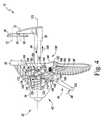
ここで図4〜7を参照すると、案内12のクランプ作動機構42がより詳細に示されている。上記のように、クランプ作動機構42は、ハウジング20の本体24から下向きに延在するトリガーアーム44を含み、トリガーアーム44は、矢印98によって示される方向に、ハウジング20に対して締め付けブラケット22を移動させるように動作させられてもよい。トリガーアーム44は、ハンドル26に隣接して、本体24より下に位置付けられた下部レバーアーム102を含む、ボディ100を有する。ボディ100はまた、ハウジング20の本体24内に位置付けられた上部レバーアーム104も含む。 4-7, the
図4に示されるように、トリガーアーム44のボディ100は、接合部106を介して本体24に取り付けられる。接合部106は、ボディ100を通して画定された円筒形開口部110に位置付けられた円筒形ピン108と、ハウジング20の本体24に画定された一対の取付穴(図示せず)と、を含む。そのようにして、トリガーアーム44は、図4に示される伸長位置と、図5に示される圧縮位置と、の間で、ハウジング20に対して枢動するように構成される。 As shown in FIG. 4, the
クランプ作動機構42はまた、前面114と後面116とを有する、作動プレート112も含む。図4〜7に示されるように、トリガーアーム44の上部レバーアーム104は、作動プレート112の前面114に係合するカム表面118を含む。クランプ作動機構42はまた、例えば、バネ120等の付勢要素を含み、それは、締め付けブラケット22のビーム36の上を通って延在し、作動プレート112の後面116とハウジング20の内壁122との間に位置付けられる。バネ120は、図4に示される伸長位置でクランプ作動機構42に付勢するように構成される。 The
クランプ作動機構42の作動プレート112は、プレート112の表面114、116を通って延在する閉鎖スロット124を有する。図4に示されるように、作動プレート112は、ビーム36の上を通って位置付けられ、ビーム36は、スロット124を通って延在する。スロット124は、表面114と116との間に延在する内壁126によって画定される。作動プレート112の内壁126は、ビーム36の上面132及び下面134をそれぞれ把持する、一対の係合エッジ128、130を含む。 The
器具10の案内12はまた、ハウジング20に対する締め付けブラケット22の運動を阻止する、ロック機構136も含み、矢印138によって示される方向へのブラケット22の運動を選択的に防止することを含む。ロック機構136は、ハウジング20の本体24に位置付けられたロックプレート140と、ロックプレート140の下端144に取り付けられる解放ボタン142と、を含む。解放ボタン142は、成形前面146と、前面146と反対側の後面148と、を含む。ロック機構136はまた、例えば、ボタン142の後面148とハウジング20の内壁152との間に位置付けられた、バネ150等の付勢要素も含む。 The
ロックプレート140の上端154は、ハウジング20の一対のフランジ158の間に画定されたスロット156に位置付けられる。作動プレート112のように、ロックプレート140は、そこを通って延在する閉鎖スロット160を有する。図4に示されるように、ロックプレート140は、ビーム36の上を通って位置付けられ、ビーム36は、スロット160を通って延在する。スロット160は、ハウジング20に対する締め付けブラケット22の運動を阻止するために、ビーム36の上面132及び下面134をそれぞれ把持する、一対の係合エッジ164、166を有する、内壁162によって画定される。 The upper end 154 of the
使用中、外科医は、クランプ作動機構42を利用して、支持ブラケット32の取付板34に向かって、締め付けブラケット22のドリルプレート38を前進させてもよい。そうするために、外科医又は他のユーザーは、矢印46によって示される方向に、トリガーアーム44の下部レバーアーム102に力を与える。力は、作動プレート112の前面114との上部レバーアーム104のカム表面118の係合によって、トリガーアーム44から作動プレート112に移される。力が下部レバーアーム102に印加されると、作動プレート112の係合エッジ128、130は、ビーム36の上面132及び下面134をそれぞれ把持し、作動プレート112は、バネ120を押す。所定量の力がトリガーアーム44に印加されるとき、作動プレート112は、バネ120の付勢力に勝ち、ドリルプレート38は、矢印98によって示される方向に、取付板34に向かって前進する。 In use, the surgeon may utilize the
図4及び5に示されるように、トリガーアーム44の上部レバーアーム104は、トリガーアーム44がハウジング20に対して枢動する際に、作動プレート112の前面114に沿って下向きに移動する。締め付けブラケット22のビーム36は、通路40を通って作動プレート112によって引かれ、ドリルプレート38の案内穴70によって画定された縦軸72に平行に延在する軸170に沿って移動する。ハウジング20に対する締め付けブラケット22の運動は、トリガーアーム44の下部レバーアーム102が、図5に示される圧縮位置でハンドル26と接触するまで継続する。 As shown in FIGS. 4 and 5, the upper lever arm 104 of the trigger arm 44 moves downward along the
ユーザーがトリガーアーム44を解放するとき、上部レバーアーム104によって与えられる力の除去によって、作動プレート112の係合エッジ128、130は、ビーム36の表面132、134をそれぞれ係合解除する。バネ120は、矢印172によって示される方向に移動するように作動プレート112を促し、一方で、締め付けブラケット22は、ロック機構136によってハウジング20に対する位置で保持される。バネ120によって与えられる力は、作動プレート112の前面114との上部レバーアーム104のカム表面118の係合によって、作動プレート112からトリガーアーム44に移される。それにより、トリガーアーム44は、矢印174によって示される方向に、ハウジング20に対して枢動するように促され、図6に示される伸長位置に戻る。 When the user releases the trigger arm 44, the engagement edges 128, 130 of the
伸長位置において、トリガーアーム44は、ハウジング20に対して更に枢動することを阻止され、作動プレート112は、バネ120と上部レバーアーム104との間の位置でロックされる。その位置で、作動プレート112の係合エッジ128、130は、ビーム36の上面132及び下面134をそれぞれ把持する。外科医又はユーザーは、ドリルプレート38を取付板34により近く前進させるために、上記で概説された工程を繰り返してもよい。 In the extended position, the trigger arm 44 is prevented from further pivoting relative to the
外科医又は他のユーザーが、ドリルプレート38を取付板34から離して移動させたいとき、外科医は、解放ボタン142を作動させロック機構136を解放し、それにより図6及び7に示されるように、締め付けブラケット22が、矢印138によって示される方向に移動することを可能にしてもよい。そうするために、矢印168によって示される方向に、ボタン142の成形前面146に、所定量の力が印加され、バネ150によって与えられる付勢力に勝つ。十分な量の力が印加されるとき、ロックプレート140は、ロックプレート140の係合エッジ164、166が、図7に示されるように、ビーム36の表面132、134から解放されるように傾斜する。次いで、締め付けブラケット22は、ハウジング20に対する任意の位置へ、矢印138によって示される方向に、軸170に沿って手動で移動させられてもよい。ユーザーは、ビーム36の端部178上で画定された停止部176によって、締め付けブラケット22をハウジング20から取り外すことを防止される。締め付けブラケット22が所望の位置に位置するとき、ボタン142は、ロックプレート140のエッジ164、166をビーム36の表面132、134と再係合するように解放されてもよく、それにより、ハウジング20に対する締め付けブラケット22の更なる運動を防止する。 When the surgeon or other user wishes to move the
ここで図8を参照すると、圧縮ガスケット14がより詳細に示されている。ガスケット14は、ゴム等のエラストマー材から形成されるボディ180を有する。他の実施形態では、ボディ180が高分子材料から形成されてよいことが理解されるべきである。ボディ180は、凹部であり、以下で更に詳述されるように、膝蓋骨人工コンポーネント18の一部分を受容するように構成される、側面182を有する。 Referring now to FIG. 8, the
ガスケット14のボディ180は、側面182と反対側の別の側面184を有する。複数の取付プラグ92が側面184から延在する。各取付プラグ92は、ドリルプレート38の対応する案内穴70に受容されるように寸法調整される。ボディ180はまた、ドリルプレート38の締め付け表面56から延在する歯62のそれぞれを受容するように寸法調整される、側面184に画定された複数の穴190を有する。 The
タブ186は、ガスケット14のボディ180から外向きに延在する。タブ186は、ユーザーの指先を受容するように構成された1対の成形表面188を含む。使用時に、ユーザーは、表面188を把持して、ガスケット14をドリルプレート38に対して移動させてもよく、それによって患者の切除された膝蓋骨にドリルで穴を開ける準備を行うとき、ガスケット14をドリル経路から外に移動させる。そのように、ガスケット14のプラグ92は、ドリルプレート38の案内穴70の中及び外に移動され得る。
取付プラグ92は、ドリルプレート38の中央開口94の構成に実質的に対応する構成を有する、中央プラグ192を含む。具体的に、中央プラグ192は、ガスケット14が所定の配向でドリルプレート38に取り付けられるように、開口94の伸長スロット96の対応する三重(trio)に適合するようにサイズ調整及び配置される三重(trio)のアーム194を含む。 The mounting
上記のように、案内12は、図9〜12に示されるように、膝蓋骨人工コンポーネント18の埋め込みのために、患者の切除された膝蓋骨16を外科的に準備するために利用されてもよい。そうするために、外科医は、取付板34と案内12のドリルプレート38との間に切除された膝蓋骨16を位置付けてもよく、圧縮ガスケット14は案内12から分離される。図9に示されるように、患者の切除された膝蓋骨16は、切除された膝蓋骨16の前面200が、取付板34の平面の締め付け表面202に面し、切除された膝蓋骨16の切除された後面204が、ドリルプレート38の平面の締め付け表面56に面するように、プレート34と38との間に位置付けられてもよい。 As described above, the
取付板34の平面の締め付け表面202は、ドリルプレート38の平面の締め付け表面56に平行に延在し、そこから延在する複数の歯206を含む。患者の切除された膝蓋骨16がプレート34と38との間に位置付けられたとき、外科医は、患者の切除された膝蓋骨16の前面200を移動させ、平面の締め付け表面202の複数の歯206と接触させてもよい。外科医はまた、クランプ作動機構42を上記のように動作させ、取付板34に向かってドリルプレート38を前進させることによって、プレート34と38との間で患者の切除された膝蓋骨16をクランプしてもよい。 The
加えて、外科医は、案内12を使用して、膝蓋骨人工コンポーネントを選択してもよい。図10に示されるように、患者の切除された膝蓋骨16の外側縁208は、特定の寸法に対応するインジケータ80のうちの1つに含まれる。インジケータ80を使用して、外科医は、切除された膝蓋骨16の切除された後面204の最大適用範囲を提供する、膝蓋骨人工コンポーネントを選択してもよい。 In addition, the surgeon may use the
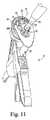
外科医が案内12のプレート34と38との間で患者の切除された膝蓋骨16をクランプした後、膝蓋骨16の切除された後面204は、膝蓋骨人工コンポーネント18を受容するように外科的に準備される。図11に示されるように、外科医は、コンポーネント18の多くの取付ペグ210の位置に対応する、表面204中の一連のパイロット穴をドリルで開けてもよい。これを行うために、外科医は、ドリルプレート38において画定された案内穴70のそれぞれに手術用ドリル74を挿入してもよい。ドリル74は、案内穴70を通って軸72に沿って前進し、表面204と接触する。外科医は、ドリル74を起動し、十分な深さのパイロット穴が患者の切除された膝蓋骨16に形成されるまで、ドリル74を案内穴70に沿って前進させる。次いで、外科医は、必要なパイロット穴が形成されるまで、案内穴70のそれぞれを通してドリル操作を反復してもよい。どの時点でも、外科医は、解放ボタン142を作動させ、患者の切除された膝蓋骨16を手動でクランプ解除し得る。 After the surgeon clamps the patient's resected
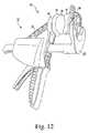
パイロット穴が切除された後面204に作製された後、外科医は、患者の切除された膝蓋骨16への取付のために膝蓋骨人工コンポーネント18を位置付け、コンポーネント18の前面212に接合剤を塗布してもよい。コンポーネント18が患者の切除された膝蓋骨16の上に位置付けられた後、ペグ210は、前面212が表面204と接触して配置されるまで、切除された後面204に形成されたパイロット穴の中に進められてもよい。圧縮ガスケット14は、ドリルプレート38に取り付けられてもよく、それにより、締め付け表面56から外向きに延在する歯62を被覆する。その位置で、ガスケット14は、ドリルプレート38とコンポーネント18との間に位置付けられる。 After the pilot hole has been created in the resected
外科医は、図12に示されるように、クランプ作動機構42を再び作動させ、コンポーネント18を患者の切除された膝蓋骨16にクランプしてもよい。そうするために、外科医は、下部レバーアーム102を握りしめ、所定量の力をトリガーアーム44に印加し、ドリルプレート38及びガスケット14を取付板34に向かって移動させてもよい。圧縮ガスケット14は、前進させられ、コンポーネント18の後方軸受表面214と接触し、コンポーネント18は、ガスケット14の凹状表面182内に位置し、それによって安定化し、重合が完了し、コンポーネント18が患者の切除された膝蓋骨16に固定されるまで、コンポーネント18が患者の切除された膝蓋骨16にしっかりとクランプされるようにする。 The surgeon may actuate the
以上、図面及び上記の説明文において本開示内容を詳細に図示、説明したが、こうした図示、説明はその性質上、例示的なものとみなすべきであって、限定的なものとみなすべきではなく、あくまで例示的実施形態を示し、説明したものにすぎないのであって、本開示の趣旨の範囲に含まれる変更及び改変はすべて保護されることが望ましい点は理解されるであろう。例えば、ガスケット14は器具10の実施形態から省かれてもよく、例えば、ドリル案内の歯は取り外し可能であるか、又は省かれる。 As described above, the present disclosure has been illustrated and described in detail in the drawings and the above description. However, such illustration and description should be regarded as illustrative in nature and not as restrictive. It will be understood that the exemplary embodiments have been shown and described only and that it is desirable to protect all changes and modifications that fall within the scope of the present disclosure. For example, the
本開示は、本明細書において述べた方法、装置、及びシステムの様々な特徴に基づく多くの利点を有するものである。本開示の方法、装置、及びシステムの代替的実施形態は、ここで述べた特徴のすべてを含むわけではないが、こうした特徴の利点の少なくとも一部から利するものである点に留意されたい。当業者であれば、本発明の1つ又は2つ以上の特徴を取り入れた、特許請求の範囲において定義される本開示の趣旨及び範囲に包含される方法、装置、及びシステムを独自に容易に実施することが可能である。 The present disclosure has many advantages based on various features of the methods, apparatus, and systems described herein. It should be noted that alternative embodiments of the disclosed methods, apparatus, and systems do not include all of the features described herein, but benefit from at least some of the advantages of these features. One of ordinary skill in the art can easily make the method, apparatus, and system within the spirit and scope of the present disclosure as defined by the claims, which incorporate one or more features of the invention. It is possible to implement.
〔実施の態様〕
(1) 整形外科用手術器具であって、
(i)第1のブラケットと、(ii)前記第1のブラケットに移動可能に連結される、第2のブラケットと、を備える、膝蓋骨ドリル案内であって、前記第2のブラケットが、中に画定された複数の案内穴を有するドリルプレートを含み、前記複数の案内穴のそれぞれが、手術用ドリルを受容するように寸法調整される、膝蓋骨ドリル案内と、
前記第2のブラケットに取り外し可能に連結される、ガスケットであって、前記第2のブラケットに連結されるとき、前記複数の案内穴を被覆するように構成される、ガスケットと、を備え、
前記ドリルプレートが、実質的に透明な材料から形成される、整形外科用手術器具。
(2) 前記第1のブラケットが、取付板を含み、前記取付板が、第1の締め付け表面を有し、前記第1の締め付け表面が、そこから延在する第1の複数の歯を有し、
前記第2のブラケットの前記ドリルプレートが、前記取付板の前記第1の締め付け表面に面する、第1の締め付け表面を含み、前記ドリルプレートの前記第1の締め付け表面が、そこから延在する、第2の複数の歯を有する、実施態様1に記載の整形外科用手術器具。
(3) 前記取付板の前記第1の締め付け表面が、前記ドリルプレートの前記第1の締め付け表面に実質的に平行に延在する、実施態様2に記載の整形外科用手術器具。
(4) 前記ガスケットが、前記ドリルプレートの前記第1の締め付け表面と接触するように構成される、第1の表面を有し、前記ガスケットの前記第1の表面が、その中に画定された複数の位置決め穴を有し、前記複数の位置決め穴が、前記ドリルプレートの前記第2の複数の歯を受容するように構成される、実施態様2に記載の整形外科用手術器具。
(5) 前記ガスケットが、前記第1の表面の反対側の第2の凹部表面を有する、実施態様4に記載の整形外科用手術器具。Embodiment
(1) An orthopedic surgical instrument,
A patella drill guide comprising: (i) a first bracket; and (ii) a second bracket movably coupled to the first bracket, wherein the second bracket is disposed therein A patella drill guide including a drill plate having a plurality of defined guide holes, each of the plurality of guide holes being sized to receive a surgical drill;
A gasket removably coupled to the second bracket, the gasket configured to cover the plurality of guide holes when coupled to the second bracket;
An orthopedic surgical instrument, wherein the drill plate is formed from a substantially transparent material.
(2) The first bracket includes a mounting plate, the mounting plate has a first clamping surface, and the first clamping surface has a first plurality of teeth extending therefrom. And
The drill plate of the second bracket includes a first clamping surface facing the first clamping surface of the mounting plate, and the first clamping surface of the drill plate extends therefrom. The orthopedic surgical instrument of claim 1, having a second plurality of teeth.
(3) The orthopedic surgical instrument of
(4) The gasket has a first surface configured to contact the first clamping surface of the drill plate, and the first surface of the gasket is defined therein. The orthopedic surgical instrument of
5. The orthopedic surgical instrument according to embodiment 4, wherein the gasket has a second recessed surface opposite the first surface.
(6) 前記ドリルプレートの前記第1の締め付け表面が、その中に画定された複数のエッチングマークを有し、各エッチングマークが、患者の膝蓋骨の寸法に対応する、実施態様2に記載の整形外科用手術器具。
(7) 前記複数のエッチングマークが、前記ドリルプレートの前記第1の締め付け表面に画定された複数の内接線として配置される、実施態様6に記載の整形外科用手術器具。
(8) 前記ドリルプレートが、前記第1の締め付け表面の反対側に位置付けられた前面を有し、
各内接線が前記前面を通して見える、実施態様7に記載の整形外科用手術器具。
(9) 前記取付板及び前記ドリルプレートが、高分子材料から形成される、実施態様2に記載の整形外科用手術器具。
(10) 前記ドリルプレートに取り付けられる複数の金属ブッシングをさらに備え、各金属ブッシングが、前記複数の案内穴のうちの対応する1つを画定する、実施態様9に記載の整形外科用手術器具。6. The shaping of
7. The orthopedic surgical instrument of
(8) the drill plate has a front surface positioned opposite the first clamping surface;
The orthopedic surgical instrument of embodiment 7, wherein each inscribed line is visible through the front surface.
(9) The surgical instrument for orthopedic surgery according to
The orthopedic surgical instrument of claim 9, further comprising a plurality of metal bushings attached to the drill plate, each metal bushing defining a corresponding one of the plurality of guide holes.
(11) 前記ドリルプレートの前記複数の案内穴が、三角形のパターンに配置される、実施態様1に記載の整形外科用手術器具。
(12) 前記ガスケットが、エラストマー材から形成される、実施態様1に記載の整形外科用手術器具。
(13) 整形外科用手術器具であって、
ハンドルと第1のブラケットとを含む、ハウジングであって、前記第1のブラケットが、取付板と、そこから延在する複数の歯とを有する、ハウジングと、
前記ハウジングに移動可能に連結される、第2のブラケットであって、(i)前記第1のブラケットの前記取付板から離間しており、複数の案内穴を含む、ドリルプレートであって、前記案内穴のそれぞれが、手術用ドリルを受容するように寸法調整される、ドリルプレートと、(ii)前記ドリルプレートから前記取付板に向かって延在する、複数の歯と、を有する、第2のブラケットと、
前記ハウジング及び前記第2のブラケットに連結される、クランプ作動機構であって、前記第1のブラケットに向かって第1の方向に前記第2のブラケットを移動させるように動作可能である、クランプ作動機構と、を備える、整形外科用手術器具。
(14) (i)前記複数の案内穴のそれぞれがそこを通って延在する縦軸を有し、(ii)前記第2のブラケットが、前記ハウジングに移動可能に連結されるビームを含み、前記ビームが、前記案内穴の前記縦軸に平行に延在する軸に沿って、前記ハウジングに対して移動するように構成される、実施態様13に記載の整形外科用手術器具。
(15) 前記クランプ作動機構が、(i)前記ハウジングに位置付けられ、前記ビームに係合するように構成される、作動プレートであって、フォロワ表面を含む、作動プレートと、(ii)前記ハウジングに枢動可能に連結される、レバーと、を含み、前記レバーが、第1の位置と第2の位置との間で移動可能であるようにし、前記レバーが前記第1の位置から前記第2の位置に移動するとき、前記作動プレートの前記フォロワ表面に係合するように構成される、カム表面を前記レバーが含み、前記作動プレートが前記ビームに係合し、前記第1の方向に前記軸に沿って前記第2のブラケットを移動させる、実施態様14に記載の整形外科用手術器具。(11) The surgical instrument for orthopedic surgery according to embodiment 1, wherein the plurality of guide holes of the drill plate are arranged in a triangular pattern.
(12) The surgical instrument for orthopedic surgery according to embodiment 1, wherein the gasket is formed of an elastomer material.
(13) an orthopedic surgical instrument,
A housing including a handle and a first bracket, the first bracket having a mounting plate and a plurality of teeth extending therefrom;
A second bracket movably coupled to the housing; (i) a drill plate spaced apart from the mounting plate of the first bracket and including a plurality of guide holes; Each of the guide holes has a drill plate sized to receive a surgical drill and (ii) a plurality of teeth extending from the drill plate toward the mounting plate; With brackets,
A clamp actuation mechanism coupled to the housing and the second bracket, the clamp actuation mechanism operable to move the second bracket in a first direction toward the first bracket. An orthopedic surgical instrument comprising a mechanism.
(14) (i) each of the plurality of guide holes has a longitudinal axis extending therethrough; (ii) the second bracket includes a beam movably coupled to the housing; The orthopedic surgical instrument of claim 13, wherein the beam is configured to move relative to the housing along an axis extending parallel to the longitudinal axis of the guide hole.
(15) the clamp actuating mechanism is (i) an actuating plate positioned on the housing and configured to engage the beam, the actuating plate including a follower surface; and (ii) the housing A lever pivotally coupled to the lever, wherein the lever is movable between a first position and a second position, and the lever is moved from the first position to the first position. The lever includes a cam surface configured to engage the follower surface of the actuating plate when moved to the position of 2, wherein the actuating plate engages the beam in the first direction. The orthopedic surgical instrument of
(16) 前記クランプ作動機構が、前記作動プレートと前記ハウジングの内壁との間に位置付けられた、付勢要素を含む、実施態様15に記載の整形外科用手術器具。
(17) 更に、前記第1のブラケットから離れた第2の方向への前記第2のブラケットの運動を選択的に阻止するように構成される、ロック機構を備える、実施態様14に記載の整形外科用手術器具。
(18) 前記ロック機構が、
ロックプレートであって、(i)前記ロックプレートが前記第2のブラケットの前記第2の方向への運動を阻止するように前記ビームに係合する、第1の位置と、(ii)前記第2のブラケットが前記第2の方向に移動できるように前記ロックプレートが前記ビームから解放される、第2の位置と、の間で移動可能な、ロックプレートと、
前記ロックプレートと前記ハウジングとの間に位置付けられた、付勢要素であって、前記第1の位置で前記ロックプレートを付勢する、付勢要素と、を備える、実施態様17に記載の整形外科用手術器具。
(19) 前記ロックプレートに取り付けられる解放ボタンを更に備える、実施態様18に記載の整形外科用手術器具。
(20) 整形外科用手術器具であって、
ハンドルと第1のブラケットとを含む、ポリマーハウジングであって、前記第1のブラケットが、取付板と、そこから延在する複数の歯と、を有する、ポリマーハウジングと、
前記ハウジングに移動可能に連結される第2のブラケットであって、前記第2のブラケットが、実質的に透明な材料から形成されるドリルプレートを有し、前記ドリルプレートが、(i)締め付け表面と、(ii)前面と、(iii)前記締め付け表面及び前記前面を通って延在する、複数の案内穴であって、前記案内穴のそれぞれが、手術用ドリルを受容するように寸法調整される、複数の案内穴と、(iv)前記ドリルプレートの前記締め付け表面に画定された、複数のエッチングマークと、を含み、前記複数のエッチングマークが前記前面を通して見える、第2のブラケットと、
前記ポリマーハウジング及び前記第2のブラケットに連結される、クランプ作動機構であって、前記第1のブラケットに向かって第1の方向に前記第2のブラケットを移動させるように動作可能である、クランプ作動機構と、
前記ハウジング及び前記第2のブラケットに連結される、ロック機構であって、前記第1のブラケットから離れた第2の方向への前記第2のブラケットの運動を選択的に阻止するように構成される、ロック機構と、を備える、整形外科用手術器具。16. The orthopedic surgical instrument of claim 15, wherein the clamp actuation mechanism includes a biasing element positioned between the actuation plate and the inner wall of the housing.
The shaping of
(18) The locking mechanism is
A first position, wherein: (i) the lock plate engages the beam to prevent movement of the second bracket in the second direction; and (ii) the first A locking plate movable between a second position, wherein the locking plate is released from the beam so that two brackets can move in the second direction;
18. The shaping of claim 17, comprising a biasing element positioned between the lock plate and the housing, the biasing element biasing the lock plate in the first position. Surgical instruments.
19. The orthopedic surgical instrument of
(20) an orthopedic surgical instrument,
A polymer housing including a handle and a first bracket, the first bracket having a mounting plate and a plurality of teeth extending therefrom;
A second bracket movably coupled to the housing, the second bracket having a drill plate formed of a substantially transparent material, the drill plate comprising: (i) a clamping surface (Ii) a front surface; and (iii) a plurality of guide holes extending through the clamping surface and the front surface, each of the guide holes being sized to receive a surgical drill. A second bracket comprising: (iv) a plurality of etching marks defined on the clamping surface of the drill plate, wherein the plurality of etching marks are visible through the front surface;
A clamp actuation mechanism coupled to the polymer housing and the second bracket, the clamp operable to move the second bracket in a first direction toward the first bracket An operating mechanism;
A locking mechanism coupled to the housing and the second bracket, the locking mechanism configured to selectively prevent movement of the second bracket in a second direction away from the first bracket. An orthopedic surgical instrument comprising a locking mechanism.
Claims (12)
Translated fromJapanese(i)第1のブラケットと、(ii)前記第1のブラケットに移動可能に連結される、第2のブラケットと、を備える、膝蓋骨ドリル案内であって、前記第2のブラケットが、中に画定された複数の案内穴を有するドリルプレートを含み、前記複数の案内穴のそれぞれが、手術用ドリルを受容するように寸法調整される、膝蓋骨ドリル案内と、
前記第2のブラケットに取り外し可能に連結される、ガスケットであって、前記第2のブラケットに連結されるとき、前記複数の案内穴を被覆するように構成される、ガスケットと、を備え、
前記ドリルプレートが、実質的に透明な材料から形成される、整形外科用手術器具。An orthopedic surgical instrument,
A patella drill guide comprising: (i) a first bracket; and (ii) a second bracket movably coupled to the first bracket, wherein the second bracket is disposed therein A patella drill guide including a drill plate having a plurality of defined guide holes, each of the plurality of guide holes being sized to receive a surgical drill;
A gasket removably coupled to the second bracket, the gasket configured to cover the plurality of guide holes when coupled to the second bracket;
An orthopedic surgical instrument, wherein the drill plate is formed from a substantially transparent material.
前記第2のブラケットの前記ドリルプレートが、前記取付板の前記第1の締め付け表面に面する、第1の締め付け表面を含み、前記ドリルプレートの前記第1の締め付け表面が、そこから延在する、第2の複数の歯を有する、請求項1に記載の整形外科用手術器具。The first bracket includes a mounting plate, the mounting plate has a first clamping surface, and the first clamping surface has a first plurality of teeth extending therefrom;
The drill plate of the second bracket includes a first clamping surface facing the first clamping surface of the mounting plate, and the first clamping surface of the drill plate extends therefrom. The orthopedic surgical instrument of claim 1, having a second plurality of teeth.
各内接線が前記前面を通して見える、請求項7に記載の整形外科用手術器具。The drill plate has a front surface positioned opposite the first clamping surface;
The orthopedic surgical instrument of claim 7, wherein each inscribed line is visible through the front surface.
Applications Claiming Priority (3)
| Application Number | Priority Date | Filing Date | Title |
|---|---|---|---|
| US201161503419P | 2011-06-30 | 2011-06-30 | |
| US61/503,419 | 2011-06-30 | ||
| PCT/US2012/044947WO2013003730A1 (en) | 2011-06-30 | 2012-06-29 | Patella clamp and drill guide surgical instrument |
Related Child Applications (1)
| Application Number | Title | Priority Date | Filing Date |
|---|---|---|---|
| JP2016189762ADivisionJP6271668B2 (en) | 2011-06-30 | 2016-09-28 | Surgical instrument for patella clamp and drill guided surgery |
Publications (2)
| Publication Number | Publication Date |
|---|---|
| JP2014525775A JP2014525775A (en) | 2014-10-02 |
| JP6072027B2true JP6072027B2 (en) | 2017-02-01 |
Family
ID=47424564
Family Applications (2)
| Application Number | Title | Priority Date | Filing Date |
|---|---|---|---|
| JP2014519144AActiveJP6072027B2 (en) | 2011-06-30 | 2012-06-29 | Surgical instrument for patella clamp and drill guided surgery |
| JP2016189762AActiveJP6271668B2 (en) | 2011-06-30 | 2016-09-28 | Surgical instrument for patella clamp and drill guided surgery |
Family Applications After (1)
| Application Number | Title | Priority Date | Filing Date |
|---|---|---|---|
| JP2016189762AActiveJP6271668B2 (en) | 2011-06-30 | 2016-09-28 | Surgical instrument for patella clamp and drill guided surgery |
Country Status (8)
| Country | Link |
|---|---|
| US (2) | US8951262B2 (en) |
| EP (2) | EP2901947B1 (en) |
| JP (2) | JP6072027B2 (en) |
| CN (1) | CN103841908B (en) |
| AU (1) | AU2012275191B2 (en) |
| ES (1) | ES2576965T3 (en) |
| WO (1) | WO2013003730A1 (en) |
| ZA (1) | ZA201400702B (en) |
Families Citing this family (22)
| Publication number | Priority date | Publication date | Assignee | Title |
|---|---|---|---|---|
| US8821501B2 (en) | 2010-09-24 | 2014-09-02 | Depuy (Ireland) | Patella resectioning guide and assembly |
| US8986306B2 (en) | 2011-06-30 | 2015-03-24 | Depuy (Ireland) | Patella orthopaedic surgical method |
| US8968321B2 (en) | 2011-06-30 | 2015-03-03 | Depuy (Ireland) | Patella resection guide with locating features and method of using the same |
| US8979854B2 (en) | 2011-06-30 | 2015-03-17 | Depuy (Ireland) | Patella orthopaedic surgical instrument assembly |
| ES2576965T3 (en) | 2011-06-30 | 2016-07-12 | Depuy (Ireland) | Ball joint clamp and surgical instrument drill guide |
| US8998912B2 (en) | 2011-09-28 | 2015-04-07 | Depuy (Ireland) | Clamping patella drill guide |
| US9078676B2 (en) | 2011-09-28 | 2015-07-14 | Depuy (Ireland) | Patella drilling system |
| US8998913B2 (en) | 2011-09-28 | 2015-04-07 | Depuy (Ireland) | Patella resection assembly |
| US9078772B2 (en) | 2011-09-28 | 2015-07-14 | Depuy (Ireland) | Rotatable patella drill guide |
| US8915923B2 (en) | 2011-09-28 | 2014-12-23 | Depuy (Ireland) | Patella resection assembly |
| US9554813B2 (en) | 2012-09-28 | 2017-01-31 | Depuy Ireland Unlimited Company | Patella drill guide and trial surgical instrument |
| US10085758B2 (en) | 2012-09-28 | 2018-10-02 | Depuy Ireland Unlimited Company | Patella drill guide and trial surgical instrument having an alignment bore formed therein and method of using the same |
| US10335163B2 (en) | 2013-03-05 | 2019-07-02 | Depuy Ireland Unlimited Company | Polymer 4-in-2 femoral cutting instrument having separable A/P and chamfer cutting blocks |
| EP3027364A4 (en)* | 2013-08-01 | 2016-08-31 | Brand Developers Aust Pty Ltd | Drilling jig |
| EP3072462B1 (en) | 2015-03-27 | 2017-10-04 | DePuy Ireland Unlimited Company | Orthopaedic surgical instrument system |
| US10695073B2 (en) | 2017-08-22 | 2020-06-30 | Arthrex, Inc. | Control system for retrograde drill medical device |
| US10034679B1 (en)* | 2017-10-31 | 2018-07-31 | Boyer Anderson, LLC | Artificial prosthesis installation clamp and method |
| US11642138B2 (en)* | 2020-06-05 | 2023-05-09 | Smith & Nephew, Inc. | Patella clamp |
| US11723677B2 (en) | 2020-10-16 | 2023-08-15 | Howmedica Osteonics Corp. | Patella resection guide with independent adjustment |
| US20220339433A1 (en)* | 2021-04-26 | 2022-10-27 | Manicka Institute Llc | Subcutaneous device for preventing and treating atherosclerosis |
| US12076025B2 (en) | 2022-05-11 | 2024-09-03 | DePuy Synthes Products, Inc. | Polymer cutting block |
| EP4563123A1 (en)* | 2023-11-29 | 2025-06-04 | Aesculap AG | Patella trial implant and system comprising a patella trial implant and a drilling guide tool |
Family Cites Families (108)
| Publication number | Priority date | Publication date | Assignee | Title |
|---|---|---|---|---|
| US2181746A (en) | 1939-02-04 | 1939-11-28 | John R Siebrandt | Combination bone clamp and adjustable drill guide |
| US3835849A (en) | 1973-01-26 | 1974-09-17 | Guire G Mc | Bone clamp and adjustable drill guide |
| US4194861A (en)* | 1976-05-04 | 1980-03-25 | Keller Research & Development, Inc. | Compact dowel hole spacing and drilling device |
| US4191861A (en) | 1977-01-24 | 1980-03-04 | Walker Equipment & Service Co. | Telephone amplifier |
| USD260927S (en) | 1979-03-14 | 1981-09-22 | Glenn Edward C | Dowell pin positioner |
| USD281622S (en) | 1983-08-29 | 1985-12-03 | Diamond Michael K | Combined dental mirror and moisture control apparatus |
| US4565192A (en) | 1984-04-12 | 1986-01-21 | Shapiro James A | Device for cutting a patella and method therefor |
| US4692073A (en) | 1985-02-25 | 1987-09-08 | Martindell J Richard | Handle adapter and chuck apparatus for power bits |
| US4633862A (en) | 1985-05-30 | 1987-01-06 | Petersen Thomas D | Patellar resection sawguide |
| US5250050A (en) | 1987-02-07 | 1993-10-05 | Pfizer Hospital Products Group, Inc. | Apparatus for knee prosthesis |
| US5116338A (en)* | 1988-02-03 | 1992-05-26 | Pfizer Hospital Products Group, Inc. | Apparatus for knee prosthesis |
| US5002547A (en) | 1987-02-07 | 1991-03-26 | Pfizer Hospital Products Group, Inc. | Apparatus for knee prosthesis |
| US5382254A (en) | 1989-07-18 | 1995-01-17 | United States Surgical Corporation | Actuating handle for surgical instruments |
| US5129908A (en) | 1990-01-23 | 1992-07-14 | Petersen Thomas D | Method and instruments for resection of the patella |
| US5021055A (en) | 1990-09-19 | 1991-06-04 | Intermedics Orthopedics, Inc. | Patellar clamp and surgical saw guide |
| US5174693A (en)* | 1990-09-28 | 1992-12-29 | Lee Valley Tools Ltd. | Drilling jig |
| US5129907A (en)* | 1990-12-10 | 1992-07-14 | Zimmer, Inc. | Patellar clamp and reamer with adjustable stop |
| US5222955A (en) | 1991-02-08 | 1993-06-29 | Mikhail Michael W E | Method for implanting a patellar prosthesis |
| US5180384A (en)* | 1991-02-08 | 1993-01-19 | Mikhail Michael W E | Method for implanting a patellar prosthesis |
| US5108401A (en) | 1991-04-12 | 1992-04-28 | New York Society For The Relief Of The Ruptured And Crippled, Maintaining The Hospital For Special Surgery | Patella cutting clamp |
| US5147365A (en) | 1991-08-19 | 1992-09-15 | Intermedics Orthopedics, Inc. | Patellar osteotomy guide |
| US5258032A (en) | 1992-04-03 | 1993-11-02 | Bertin Kim C | Knee prosthesis provisional apparatus and resection guide and method of use in knee replacement surgery |
| US5484451A (en) | 1992-05-08 | 1996-01-16 | Ethicon, Inc. | Endoscopic surgical instrument and staples for applying purse string sutures |
| US5312409A (en)* | 1992-06-01 | 1994-05-17 | Mclaughlin Robert E | Drill alignment guide |
| US5284485A (en) | 1992-09-16 | 1994-02-08 | Ethicon, Inc. | Endoscopic knotting device |
| US5415663A (en) | 1993-12-02 | 1995-05-16 | Johnson & Johnson Orthopaedics, Inc. | Orthopaedic cutting guides with retractable saw blade slots |
| US6074425A (en) | 1994-01-14 | 2000-06-13 | Biomedical Engineering Trust I | Fixed bearing joint endoprosthesis |
| US5536271A (en)* | 1994-06-02 | 1996-07-16 | Depuy, Inc. | Patella reaming system |
| USD367531S (en) | 1994-06-27 | 1996-02-27 | Zimmer, Inc. | External fixation clamp |
| US5470328A (en) | 1994-07-21 | 1995-11-28 | Snowden-Pencer, Inc. | Surgical instrument handle and actuator means |
| US5810827A (en) | 1994-09-02 | 1998-09-22 | Hudson Surgical Design, Inc. | Method and apparatus for bony material removal |
| US5611802A (en) | 1995-02-14 | 1997-03-18 | Samuelson; Kent M. | Method and apparatus for resecting bone |
| US5575793A (en) | 1995-02-15 | 1996-11-19 | Smith & Nephew Richards Inc. | Patella clamp apparatus |
| US5593450A (en) | 1995-02-27 | 1997-01-14 | Johnson & Johnson Professional, Inc. | Oval domed shaped patella prosthesis |
| US5520692A (en) | 1995-02-28 | 1996-05-28 | Wright Medical Technology, Inc. | Adjustable depth patella recessing guide and method |
| US5626607A (en) | 1995-04-03 | 1997-05-06 | Heartport, Inc. | Clamp assembly and method of use |
| US5542947A (en) | 1995-05-12 | 1996-08-06 | Huwmedica Inc. | Slotted patella resection guide and stylus |
| US5968051A (en)* | 1995-07-27 | 1999-10-19 | Johnson & Johnson Professional, Inc. | Patella clamping device |
| FR2737848B1 (en) | 1995-08-16 | 2000-03-03 | Lanternier Hubert | INSTRUMENTATION FOR THE PLACEMENT OF A PROSTHETIC JOINT IMPLANT |
| US5582615A (en) | 1995-10-30 | 1996-12-10 | Pilling Weck, Incorporated | Handle for surgical clip applicator systems |
| US5716361A (en) | 1995-11-02 | 1998-02-10 | Masini; Michael A. | Bone cutting guides for use in the implantation of prosthetic joint components |
| USD373635S (en) | 1995-11-14 | 1996-09-10 | Zimmer, Inc. | External fixation clamp |
| US5716362A (en) | 1996-02-20 | 1998-02-10 | Howmedica Inc. | Patella milling instrument |
| US5667512A (en) | 1996-05-03 | 1997-09-16 | Metagen, Llc | Patellar resection guide |
| US5827279A (en) | 1996-12-06 | 1998-10-27 | Ethicon Endo-Surgery, Inc. | Knife coupler mechanism for an endoscopic instrument |
| US8083745B2 (en)* | 2001-05-25 | 2011-12-27 | Conformis, Inc. | Surgical tools for arthroplasty |
| GB9804281D0 (en) | 1998-02-27 | 1998-04-22 | Johnson & Johnson Medical Ltd | Handle assembly |
| WO1999045856A1 (en) | 1998-03-13 | 1999-09-16 | Macey Theodore I | Method and apparatus for clamping |
| US5944723A (en) | 1998-03-27 | 1999-08-31 | Johnson & Johnson Professional, Inc. | Locking orthopaedic clamping tool |
| US6010509A (en)* | 1998-07-01 | 2000-01-04 | The Dana Center For Orthopaedic Implants | Patella resection drill and prosthesis implantation device |
| US6277121B1 (en)* | 1998-09-09 | 2001-08-21 | Brian D. Burkinshaw | Patella reaming system |
| US6080162A (en) | 1998-09-28 | 2000-06-27 | Depuy Orthopaedics, Inc. | Modular orthopaedic clamping tool |
| US5941884A (en) | 1998-10-09 | 1999-08-24 | Osteonics Corp. | Patella preparation apparatus and method |
| US6419675B1 (en) | 1999-09-03 | 2002-07-16 | Conmed Corporation | Electrosurgical coagulating and cutting instrument |
| US6190391B1 (en) | 1999-10-01 | 2001-02-20 | Bristol-Myers Squibb Company | Method of preparing a resected posterior surface of a patella to receive a prosthetic element |
| US7678151B2 (en) | 2000-05-01 | 2010-03-16 | Ek Steven W | System and method for joint resurface repair |
| US20020115987A1 (en) | 2001-02-16 | 2002-08-22 | Path | Needle cannula removal by extraction |
| US6551316B1 (en) | 2001-03-02 | 2003-04-22 | Beere Precision Medical Instruments, Inc. | Selective compression and distraction instrument |
| USD463550S1 (en) | 2001-03-27 | 2002-09-24 | Thomas Sherman | Eyedropper positioning device |
| USD459474S1 (en) | 2001-06-19 | 2002-06-25 | Impra, Inc. | Stent delivery apparatus |
| US6855150B1 (en) | 2001-07-13 | 2005-02-15 | Timothy R. Linehan | Patellar trial and drill guide for use in knee replacement surgery |
| US6589248B1 (en) | 2002-01-29 | 2003-07-08 | Joe L. Hughes | Patellar alignment device |
| EP1478288A4 (en) | 2002-02-26 | 2010-06-02 | Zimmer Inc | Patella resection guide |
| TW527913U (en) | 2002-07-22 | 2003-04-11 | Jeng-Jie Jiang | Structure of brush head for electromotive toothbrush |
| US6866667B2 (en) | 2002-09-03 | 2005-03-15 | Symmetry Medical, Inc. | Patellar milling clamp |
| US20040153066A1 (en) | 2003-02-03 | 2004-08-05 | Coon Thomas M. | Apparatus for knee surgery and method of use |
| US20040162561A1 (en)* | 2003-02-13 | 2004-08-19 | Howmedica Osteonics Corp. | Modular patella instrument |
| GB2401550B (en) | 2003-05-12 | 2005-04-20 | Corin Ltd | Head centering jig for femoral resurfacing |
| US7210880B2 (en) | 2003-11-13 | 2007-05-01 | Black & Decker Inc. | Lock set installation apparatus and kit and method of using the same |
| US20050240196A1 (en)* | 2004-03-09 | 2005-10-27 | Davis Kenneth P | Apparatus for use in orthopaedic surgery |
| WO2005110249A1 (en) | 2004-05-17 | 2005-11-24 | Imp Limited | Apparatus for use in orthopaedic surgery |
| GB0420346D0 (en) | 2004-09-13 | 2004-10-13 | Finsbury Dev Ltd | Tool |
| US7686533B2 (en) | 2004-10-22 | 2010-03-30 | Howmedia Osteonics Corp. | Universal coupler |
| US7566335B1 (en) | 2004-11-22 | 2009-07-28 | Biomet Manufacturing Corp. | Method and apparatus for patella resection |
| US7632279B2 (en) | 2004-12-27 | 2009-12-15 | Howmedica Osteonics Corp. | Patella resection clamp |
| GB0510111D0 (en) | 2005-05-18 | 2005-06-22 | Photonics The | Patellar resection tool |
| US8021365B2 (en) | 2005-07-11 | 2011-09-20 | Kyphon Sarl | Surgical device having interchangeable components and methods of use |
| EP1931264A1 (en) | 2005-10-07 | 2008-06-18 | Alphatec Spine, Inc. | Retractor and methods of use |
| US20070179626A1 (en) | 2005-11-30 | 2007-08-02 | De La Barrera Jose L M | Functional joint arthroplasty method |
| GB0526385D0 (en) | 2005-12-28 | 2006-02-08 | Mcminn Derek J W | Improvements in or relating to knee prosthesis |
| WO2007106516A2 (en) | 2006-03-14 | 2007-09-20 | Ralph Scott Oliver | Apparatus and method for implementing patella resection guide during minimally invasive surgery |
| GB0607027D0 (en) | 2006-04-07 | 2006-05-17 | Depuy Int Ltd | Patella tracking |
| USD549331S1 (en) | 2006-09-13 | 2007-08-21 | Senko Medical Instrument Mfg., Co. | Patella trap retractor for knee arthroplasty |
| US20080097450A1 (en)* | 2006-09-14 | 2008-04-24 | Zimmer Technology, Inc. | Patella clamp |
| ES2337712T3 (en) | 2006-10-12 | 2010-04-28 | WALDEMAR LINK GMBH & CO. KG | MODULAR ROTULAR INSTRUMENTAL. |
| US7758651B2 (en) | 2006-10-18 | 2010-07-20 | Howmedica Osteonics Corp. | Mis patellar preparation |
| US8147497B2 (en) | 2007-03-02 | 2012-04-03 | Greatbatch Medical S.A. | In situ patellar fixing system |
| US8628560B2 (en)* | 2007-03-08 | 2014-01-14 | DePuy Synthes Products, LLC | Orthopaedic instrumentation with integral load-bearing members |
| WO2008112996A1 (en) | 2007-03-14 | 2008-09-18 | Conformis, Inc. | Surgical tools for arthroplasty |
| EP2194889B1 (en) | 2007-09-30 | 2015-09-23 | DePuy Products, Inc. | Customized patient-specific orthopaedic surgical instrumentation |
| US7972383B2 (en) | 2008-06-30 | 2011-07-05 | Depuy Products, Inc. | Implantable patella component having a thickened superior edge |
| US8092544B2 (en) | 2008-06-30 | 2012-01-10 | Depuy Products, Inc. | Implantable patella component having a thickened superior edge |
| US8740911B2 (en) | 2008-11-07 | 2014-06-03 | Howmedica Osteonics Corp. | Method of preparing a femur for implantation of a femoral implant |
| US9375221B2 (en) | 2008-12-29 | 2016-06-28 | Depuy (Ireland) | Orthopaedic cutting block having a chemically etched metal insert |
| USD638541S1 (en) | 2010-05-28 | 2011-05-24 | Zimmer, Inc. | Femoral prosthesis insertion tool |
| USD642678S1 (en) | 2010-06-01 | 2011-08-02 | Zimmer, Inc. | Pin pulling tool |
| USD646389S1 (en) | 2010-06-01 | 2011-10-04 | Zimmer, Inc. | Patella osteotomy guide |
| USD634011S1 (en) | 2010-07-29 | 2011-03-08 | Michael Phillips | Surgical clip |
| US8821501B2 (en) | 2010-09-24 | 2014-09-02 | Depuy (Ireland) | Patella resectioning guide and assembly |
| US8979854B2 (en) | 2011-06-30 | 2015-03-17 | Depuy (Ireland) | Patella orthopaedic surgical instrument assembly |
| US8986306B2 (en) | 2011-06-30 | 2015-03-24 | Depuy (Ireland) | Patella orthopaedic surgical method |
| US8968321B2 (en) | 2011-06-30 | 2015-03-03 | Depuy (Ireland) | Patella resection guide with locating features and method of using the same |
| US20130030443A1 (en) | 2011-06-30 | 2013-01-31 | Wright Abraham P | Patella drill guide and clamp assembly |
| ES2576965T3 (en) | 2011-06-30 | 2016-07-12 | Depuy (Ireland) | Ball joint clamp and surgical instrument drill guide |
| US9078772B2 (en) | 2011-09-28 | 2015-07-14 | Depuy (Ireland) | Rotatable patella drill guide |
| US9078676B2 (en) | 2011-09-28 | 2015-07-14 | Depuy (Ireland) | Patella drilling system |
| US8998912B2 (en) | 2011-09-28 | 2015-04-07 | Depuy (Ireland) | Clamping patella drill guide |
| US20130211410A1 (en) | 2012-02-07 | 2013-08-15 | Conformis, Inc. | Patella Resection Instrument Guide Having Optional Patient-Specific Features |
- 2012
- 2012-06-29ESES12803797.5Tpatent/ES2576965T3/enactiveActive
- 2012-06-29USUS13/538,086patent/US8951262B2/enactiveActive
- 2012-06-29JPJP2014519144Apatent/JP6072027B2/enactiveActive
- 2012-06-29AUAU2012275191Apatent/AU2012275191B2/enactiveActive
- 2012-06-29EPEP15154630.6Apatent/EP2901947B1/enactiveActive
- 2012-06-29CNCN201280032658.XApatent/CN103841908B/enactiveActive
- 2012-06-29WOPCT/US2012/044947patent/WO2013003730A1/enactiveApplication Filing
- 2012-06-29EPEP12803797.5Apatent/EP2725992B1/enactiveActive
- 2014
- 2014-01-29ZAZA2014/00702Apatent/ZA201400702B/enunknown
- 2015
- 2015-02-10USUS14/618,515patent/US9414851B2/enactiveActive
- 2016
- 2016-09-28JPJP2016189762Apatent/JP6271668B2/enactiveActive
Also Published As
| Publication number | Publication date |
|---|---|
| JP2014525775A (en) | 2014-10-02 |
| EP2725992A1 (en) | 2014-05-07 |
| EP2901947A1 (en) | 2015-08-05 |
| US20150216543A1 (en) | 2015-08-06 |
| US9414851B2 (en) | 2016-08-16 |
| ES2576965T3 (en) | 2016-07-12 |
| JP6271668B2 (en) | 2018-01-31 |
| EP2725992B1 (en) | 2016-03-23 |
| JP2016215017A (en) | 2016-12-22 |
| EP2725992A4 (en) | 2015-05-06 |
| CN103841908A (en) | 2014-06-04 |
| WO2013003730A1 (en) | 2013-01-03 |
| US8951262B2 (en) | 2015-02-10 |
| CN103841908B (en) | 2016-08-17 |
| US20130023890A1 (en) | 2013-01-24 |
| ZA201400702B (en) | 2016-10-26 |
| AU2012275191B2 (en) | 2016-12-15 |
| AU2012275191A1 (en) | 2014-01-23 |
| EP2901947B1 (en) | 2016-07-20 |
Similar Documents
| Publication | Publication Date | Title |
|---|---|---|
| JP6271668B2 (en) | Surgical instrument for patella clamp and drill guided surgery | |
| EP2540234B1 (en) | Patella resection guide with locating features | |
| JP6112535B2 (en) | Patella orthopedic surgical instrument assembly | |
| EP2540239B1 (en) | Patella drill guide and clamp assembly | |
| US8986306B2 (en) | Patella orthopaedic surgical method | |
| JP6029872B2 (en) | Orthopedic instrument system | |
| EP2556801B1 (en) | Patella resection assembly | |
| JP2013013728A5 (en) | ||
| JP6138445B2 (en) | Patella resection assembly | |
| US8998913B2 (en) | Patella resection assembly |
Legal Events
| Date | Code | Title | Description |
|---|---|---|---|
| A621 | Written request for application examination | Free format text:JAPANESE INTERMEDIATE CODE: A621 Effective date:20150604 | |
| A131 | Notification of reasons for refusal | Free format text:JAPANESE INTERMEDIATE CODE: A131 Effective date:20160628 | |
| A521 | Request for written amendment filed | Free format text:JAPANESE INTERMEDIATE CODE: A523 Effective date:20160928 | |
| TRDD | Decision of grant or rejection written | ||
| A01 | Written decision to grant a patent or to grant a registration (utility model) | Free format text:JAPANESE INTERMEDIATE CODE: A01 Effective date:20161206 | |
| A61 | First payment of annual fees (during grant procedure) | Free format text:JAPANESE INTERMEDIATE CODE: A61 Effective date:20161227 | |
| R150 | Certificate of patent or registration of utility model | Ref document number:6072027 Country of ref document:JP Free format text:JAPANESE INTERMEDIATE CODE: R150 | |
| S531 | Written request for registration of change of domicile | Free format text:JAPANESE INTERMEDIATE CODE: R313531 | |
| S533 | Written request for registration of change of name | Free format text:JAPANESE INTERMEDIATE CODE: R313533 | |
| R350 | Written notification of registration of transfer | Free format text:JAPANESE INTERMEDIATE CODE: R350 | |
| R250 | Receipt of annual fees | Free format text:JAPANESE INTERMEDIATE CODE: R250 | |
| R250 | Receipt of annual fees | Free format text:JAPANESE INTERMEDIATE CODE: R250 | |
| R250 | Receipt of annual fees | Free format text:JAPANESE INTERMEDIATE CODE: R250 | |
| R250 | Receipt of annual fees | Free format text:JAPANESE INTERMEDIATE CODE: R250 | |
| R250 | Receipt of annual fees | Free format text:JAPANESE INTERMEDIATE CODE: R250 | |
| R250 | Receipt of annual fees | Free format text:JAPANESE INTERMEDIATE CODE: R250 |