JP6071251B2 - Self-propelled vacuum cleaner - Google Patents
Self-propelled vacuum cleanerDownload PDFInfo
- Publication number
- JP6071251B2 JP6071251B2JP2012122850AJP2012122850AJP6071251B2JP 6071251 B2JP6071251 B2JP 6071251B2JP 2012122850 AJP2012122850 AJP 2012122850AJP 2012122850 AJP2012122850 AJP 2012122850AJP 6071251 B2JP6071251 B2JP 6071251B2
- Authority
- JP
- Japan
- Prior art keywords
- self
- main body
- suction port
- propelled cleaner
- dust suction
- Prior art date
- Legal status (The legal status is an assumption and is not a legal conclusion. Google has not performed a legal analysis and makes no representation as to the accuracy of the status listed.)
- Expired - Fee Related
Links
Images


Landscapes
- Electric Vacuum Cleaner (AREA)
- Nozzles For Electric Vacuum Cleaners (AREA)
Description
Translated fromJapanese本発明は、自走式掃除機に関するものである。 The present invention relates to a self-propelled cleaner.
従来の自走式掃除機は、円状の本体の底面中央付近に塵埃吸引口と塵埃吸引口に設けられた回転ブラシを備え、本体の底面外周付近にサイドブラシを備える構成である。サイドブラシを略水平に回転して本体の外周の外側の塵埃を本体の中央側に掻き込むことで、壁面近くの塵埃を吸引している(例えば、特許文献1参照。)。
また、従来の他の自走式掃除機は、本体前方が矩形状であり、本体底面前端付近に塵埃吸込口と塵埃吸引口に設けられた回転ブラシを備える構成である。回転ブラシの回転軸と駆動輪の回転軸は平行であり、本体前方の右側面もしくは左側面が壁面に沿うように本体を移動することで、壁面近くの塵埃を吸引している(例えば、特許文献2参照。)。
また、従来の他の自走式掃除機は、円状の本体の底面左前方に先端が直角形状の吸引ノズルを収納可能に備える構成である。本体の外周から突出した吸引ノズルの側面が壁面に沿うように本体を移動することで、壁面近くの塵埃を吸引している(例えば、特許文献3参照。)。A conventional self-propelled cleaner includes a dust suction port and a rotating brush provided at the dust suction port near the center of the bottom surface of the circular main body, and a side brush near the bottom outer periphery of the main body. By rotating the side brush substantially horizontally and dusting outside the outer periphery of the main body into the center side of the main body, dust near the wall surface is sucked (for example, see Patent Document 1).
In addition, another conventional self-propelled cleaner has a rectangular shape in front of the main body, and includes a rotating brush provided in the dust suction port and the dust suction port in the vicinity of the front end of the bottom surface of the main body. The rotation axis of the rotating brush and the rotation axis of the drive wheel are parallel, and the main body is moved so that the right side surface or the left side surface in front of the main body is along the wall surface. Reference 2).
In addition, another conventional self-propelled cleaner has a configuration in which a suction nozzle having a right-angled tip is accommodated in the front left of the bottom of the circular main body. By moving the main body so that the side surface of the suction nozzle protruding from the outer periphery of the main body is along the wall surface, dust near the wall surface is sucked (see, for example, Patent Document 3).
従来の自走式掃除機では、床面の隅部等の狭い空間にサイドブラシが届かず掃除漏れが生じるという問題点があった。また、従来の自走式掃除機では、本体の移動方向に対する回転ブラシや吸引ノズルの向きが一定であり、床面の隅部等の狭い空間を掃除する際に、本体の移動方向を転換し前後進することを繰り返す必要があるため、掃除効率が悪いという問題点があった。 The conventional self-propelled cleaner has a problem that the side brush does not reach a narrow space such as a corner of the floor surface, resulting in cleaning leakage. Also, in the conventional self-propelled cleaner, the direction of the rotating brush and suction nozzle relative to the moving direction of the main body is constant, and the main body moving direction is changed when cleaning a narrow space such as a corner of the floor surface. Since it is necessary to repeat moving forward and backward, there was a problem that cleaning efficiency was poor.
本発明は、上記のような課題を解決するためになされたもので、床面の掃除漏れが少ない自走式掃除機を得るものである。また、本発明は、掃除効率が優れた自走式掃除機を得るものである。 The present invention has been made in order to solve the above-described problems, and provides a self-propelled cleaner with less floor leakage. The present invention also provides a self-propelled cleaner with excellent cleaning efficiency.
本発明に係る自走式掃除機は、床面上を転動する複数個の駆動輪を有し、底面に塵埃吸込口が設けられた本体と、本体の内部にあって塵埃吸込口から床面上の空気を吸引する送風機及び集塵部と、駆動輪と送風機を制御する制御回路を有する電気回路基板と、を備え、本体の外殻形状は、1つの頂部から連続する2つの平面状側面を有し、頂部を通り、本体を二等分する中心線を挟んで、その両側の位置に、駆動輪をそれぞれ配置し、駆動輪は、その転動方向及び転動量が互いに独立して制御回路により制御され、塵埃吸込口は、本体の底面において2つの平面状側面に沿った方向にそれぞれが細長く形成され、本体には、送風機の運転中、床面に対して水平、かつ、塵埃吸込口の長手方向に沿って配置された軸を中心として回転駆動されて床面上を回転する回転ブラシを備え、回転ブラシは、その回転中心部が、塵埃吸込口の近傍にあって、本体の最外殻面よりも外側へ常に突出して回転する。A self-propelled cleaner according to the present invention includes a main body having a plurality of drive wheels that roll on a floor surface, and a dust suction port provided on the bottom surface, and the interior of the main body and the floor from the dust suction port to the floor. A blower and a dust collecting unit for sucking air on the surface, and an electric circuit board having a control circuit for controlling the driving wheel and the blower, and the outer shell shape of the main body is two planar shapes continuous from one top has a side surface, through the top, across the center line bisecting the body, the position of both sides, a drive wheel is arranged, the drive wheel is rolling direction and rolling amount ofthat is independent of one another Thedust suction port is formed in an elongated shape in the direction along the two planar side surfaces on the bottom surface of the main body,and the main body ishorizontal to the floor surface during the operation of the blower, and It is rotatedabout an axis which is arranged along the longitudinal direction of the dust suction port Arotary brush forrotating the Menjo,rotating brushes, the rotation center portion, in the vicinity of the dust suction port, is rotated constantly protrudes outward from the outermost surface of the body.
本発明は、駆動輪の転動方向に対する塵埃吸込口の長手方向の角度が最適化されるように塵埃吸込口角度変更手段を制御する制御手段を備えることで、従来の自走式掃除機では到達できなかった箇所に塵埃吸込口を到達することが可能となり、掃除漏れを少なくすることができる。また、本発明は、駆動輪の転動方向に対する塵埃吸込口の長手方向の角度が最適化されるように塵埃吸込口角度変更手段を制御する制御手段を備えることで、従来の自走式掃除機のように、本体の移動方向の転換と前後進を繰り返す必要がなくなり、掃除効率を向上することができる。 The present invention includes a control unit that controls the dust suction port angle changing unit so that the angle of the dust suction port in the longitudinal direction with respect to the rolling direction of the drive wheel is optimized. It becomes possible to reach the dust suction port at a location that could not be reached, and to reduce cleaning leakage. In addition, the present invention includes a control unit that controls the dust suction port angle changing unit so that the angle of the dust suction port in the longitudinal direction with respect to the rolling direction of the drive wheel is optimized, thereby providing a conventional self-propelled cleaning device. Like a machine, it is not necessary to repeat the change of the moving direction of the main body and the forward and backward movement, and the cleaning efficiency can be improved.
以下、本発明の自走式掃除機について、図面を用いて説明する。
なお、各図において、同一部材、同一部分には同一の符号を付している。また、軸受けや支持部材等の細かい構造については適宜図示を省略している。また、重複する説明については、適宜簡略化或いは省略している。Hereinafter, the self-propelled cleaner of the present invention will be described with reference to the drawings.
In addition, in each figure, the same code | symbol is attached | subjected to the same member and the same part. In addition, the illustration of the fine structures such as bearings and support members is omitted as appropriate. In addition, overlapping descriptions are simplified or omitted as appropriate.
実施の形態1.
以下に、実施の形態1に係る自走式掃除機の概略構造を説明する。
(概略構造)
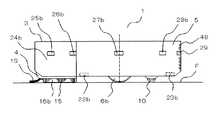
図1は、実施の形態1に係る自走式掃除機の、底面図を示す図である。
図1に示すように、実施の形態1に係る自走式掃除機は、中心角度Aが270°の円弧と円弧の両端から延長した2本の接線とによって囲まれる外形の本体1を有する。本体1は、円弧と同心の円によって分割される中央部2と外殻部3とを有する。外殻部3は、直角部4と円弧部5とを有する。外殻部3は、中央部2の周りを、図1に示す状態から時計回りに45°、反時計回りに45°の合計90°の範囲で回転可能である。また、直角部4は、外殻部3に上下移動可能に支持される。
The schematic structure of the self-propelled cleaner according to the first embodiment will be described below.
(Outline structure)
FIG. 1 is a diagram illustrating a bottom view of the self-propelled cleaner according to the first embodiment.
As shown in FIG. 1, the self-propelled cleaner according to the first embodiment has a
中央部2の内部には、一対の駆動輪6a、6bが設けられる。駆動輪6a、6bは、中央部2の底面に中心線Ba−Bbを挟んで対称に設けられた駆動輪開口部7a、7bから、下面が床面に接地するように突出する。駆動輪6a、6bは、後述する駆動輪モーター8a、8bによってそれぞれ独立に駆動され、複数のギヤを連結したギヤ部9a、9bを介して駆動輪モーター8a、8bの回転力が伝達される。中央部2には、駆動輪6a、6bの中間後方に方向転換自在な従動輪10が設けられ、駆動輪6a、6bと従動輪10とによって本体1を支持する。 A pair of
直角部4は、底面前方に右吸込口11aと左吸込口11bを有し、後述する送風機34が発生する負圧により塵埃を吸引する。右吸込口11aと左吸込口11bは、直角部4の2辺にそれぞれ平行に配置される。つまり、右吸込口11aと左吸込口11bは、互いに90°の角度で配置される。右吸込口11aと左吸込口11bには、それぞれ回転ブラシ12a、12bが設けられる。回転ブラシ12a、12bは、軸受け14によって回転自在に軸支された回転ブラシ軸13a、13bと回転ブラシ軸13a、13bに植毛された毛ブラシ15とで構成される。回転ブラシ12a、12bは、後述する回転ブラシモーター50によって駆動される。毛ブラシ15は、複数の列をなし螺旋状に植毛される。毛ブラシ15の長さは、先端が直角部4の外周から突出する長さに設定される。 The
右吸込口11aと左吸込口11bのそれぞれには、本体中心側にシート状の弾性部材、もしくは毛ブラシ列、もしくは布等からなる塵埃受け16a、16bが設けられる。塵埃受け16a、16bの上下方向の長さは、先端が床面に接触する長さに設定される。塵埃受け16a、16bは、回転ブラシ12a、12bによって床面から除去された塵埃が右吸込口11aと左吸込口11bの後方に通り抜けるのを防止し、右吸込口11aと左吸込口11bによって吸引されるように導く。 Each of the
直角部4の先端部には、水平回転する先端ブラシ17が設けられる。先端ブラシ17は、先端ブラシ軸18と先端ブラシ軸18の下端部に植毛された長さの異なる3条の毛ブラシ19とで構成される。毛ブラシ19は、先端ブラシ軸18の下端部に斜め下向きに植毛され、床面と接した際に水平方向に広がって回転する。床面と接して水平方向に広がった毛ブラシ19は、先端が直角部4の外周から突出し、本体1の外側の塵埃を掻き取る。また、毛ブラシ19は、複数の長さで構成されるため、接触する床面を均一に掃除することが可能である。 A
直角部4は、先端ブラシ17の後方に中央吸込口20を有する。中央吸込口20は、右吸込口11aと左吸込口11bの中間部に位置し、先端ブラシ17によって除去できなかった塵埃を吸引する。中央吸込口20は、直角部4の内部で右吸込口11aと左吸込口11bとに連通し、後述する送風機34の発生する負圧により塵埃を吸引する。中央吸込口20の後方には、塵埃受け21が設けられる。塵埃受け21の上下方向の長さは、先端が床面に接触する長さに設定される。塵埃受け21は、塵埃が中央吸込口20の後方に通り抜けるのを防止し、中央吸込口20によって吸引されるように導く。 The
円弧部5の底面外周部には、本体1の前進時に凹状段差を検出する左右一対の前方段差検知センサー22a、22bと後進時に凹状段差を検出する左右一対の後方段差検知センサー23a、23bとが設けられる。各段差検知センサーは、赤外線を出射する発光部と受光部とで構成され、発光部から出射されて床面で反射した赤外線を受光部で受光することにより、凹状段差の深さを検出する。制御部(図示せず)は、所定深さ以上の凹状段差が検出された場合に、本体1の移動方向を転換する。
なお、各段差検知センサーは、赤外線を出射する発光部と受光部とで構成されるものに限らず、接触式スイッチや超音波送受信器等の他のセンサーでも良い。A pair of left and right front
Each step detection sensor is not limited to a light emitting unit that emits infrared light and a light receiving unit, and may be another sensor such as a contact switch or an ultrasonic transceiver.
駆動輪6aと駆動輪6bの間隔は、回転ブラシ12aの本体後方側端部と回転ブラシ12bの本体後方側端部の間隔よりも狭く設定される。このように構成することで、回転ブラシ12a、12bを前方にして駆動輪6a、6bが正方向に転動した際に、駆動輪6a、6bが回転ブラシ12a、12bによって掃除された床面を通過するため、駆動輪6a、6bに塵埃が付着することを防止することができる。 The interval between the
図2は、実施の形態1に係る自走式掃除機の、平面図を示す図である。また、図3は、実施の形態1に係る自走式掃除機の、左側面図を示す図である。
図2、3に示すように、直角部4は、平面状の右側面24aと左側面24bを有する。右側面24aと左側面24bが交差する頂角の角度は90°であり、2つの面の結合部は丸く形成される。FIG. 2 is a plan view of the self-propelled cleaner according to the first embodiment. FIG. 3 is a left side view of the self-propelled cleaner according to the first embodiment.
As shown in FIGS. 2 and 3, the
右側面24aと左側面24bには、それぞれ所定距離だけ離間して配置された2つの右側面近接センサー25a、26aと2つの左側面近接センサー25b、26bが設けられる。各近接センサー25a、26a、25b、26bは、赤外線を出射する発光部と受光部とで構成され、発光部から出射して反射した赤外線を受光部で受光する。制御部(図示せず)は、各近接センサーの信号から壁や障害物までの距離を検出する。また、制御部(図示せず)は、同一平面にある2つの近接センサーの距離出力を比較することにより、右側面24aや左側面24bに対する壁面や障害物の角度を検出する。
また、円弧部5の側面の左右と左右後方と後方とには、右方近接センサー27aと左方近接センサー27bと右後方近接センサー28aと左後方近接センサー28bと後方近接センサー29とが設けられる。各近接センサーは、それぞれ赤外線を出射する発光部と受光部とで構成され、発光部から出射されて反射した赤外線を受光部で受光する。制御部(図示せず)は、本体1の側方や後方と壁面や障害物の距離を検出する。
なお、各近接センサーは、赤外線を出射する発光部と受光部とで構成されるものに限らず、接触式スイッチや超音波送受信器等の他のセンサーでも良い。The
A
Each proximity sensor is not limited to a light emitting unit that emits infrared light and a light receiving unit, and may be another sensor such as a contact switch or an ultrasonic transmitter / receiver.
円弧部5は、上面後方に操作表示部30を有する。操作表示部30には、電源や動作モード等の機能を切り替える複数の操作ボタン31と表示部32とが設けられる。
また、本体1の上面には、直角部4と円弧部5に亘る集塵部カバー33が設けられる。集塵部カバー33は、後述する集塵部37を本体1に着脱する際、後方を支点に回転して開閉する。The
In addition, a
以下に、実施の形態1に係る自走式掃除機の集塵部の構造を説明する。
(集塵部の構造)
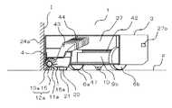
図4は、実施の形態1に係る自走式掃除機の、図1に記載されたBa−Bb線での、断面図を示す図である。
図4に示すように、円弧部5の中心には、送風機34が設けられる。送風機34は、水平回転する複数の回転翼で構成されるファン35を有し、ファン35を回転させることにより負圧を発生する。空気は、ファン35によって発生する負圧によりファン35の軸方向上側から流入し、ファン35の半径方向に設けられた排気ダクト36から排出される。Below, the structure of the dust collection part of the self-propelled cleaner which concerns on
(Dust collector structure)
4 is a cross-sectional view of the self-propelled cleaner according to the first embodiment, taken along line Ba-Bb described in FIG. 1.
As shown in FIG. 4, a
送風機34の上部には、着脱可能な集塵部37が設けられる。集塵部37は、円筒状に構成され、送風機34側に開口部を設けた集塵部蓋38を有する。集塵部蓋38は、ヒンジ部39を支点にして開閉可能である。開口部には、各吸引口より吸引された含塵空気から塵埃を分離して空気のみを通過させるフィルター40が設けられる。また、送風機34の開口部には、格子41が設けられ、集塵部37を取り外したときに異物が侵入することを防止する。 A detachable
集塵部蓋38の開口部には、集塵部37と送風機34の気密を確保する輪状のシール部材42が設けられる。シール部材42は、ゴムやエラストマー樹脂等の弾性部材に潤滑性を有するフッ素樹脂を配合した素材で構成され、断面がV字状である。集塵部蓋38の開口部と送風機34の開口部は、シール部材42のV字を形成する異なる面にそれぞれ接する。このように構成することで、集塵部37と送風機34は、気密を確保した状態で水平方向に摺動可能である。 A ring-shaped
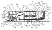
図5は、実施の形態1に係る自走式掃除機の、集塵部カバー33等を取り外した状態での、一部断面を含む平面図を示す図である。
右吸込口11aと左吸込口11bと中央吸込口20とには、集塵部37に連通する吸込風路43と自在連結部44が接続される。送風機34の発生する負圧によって右吸込口11aと左吸込口11bと中央吸込口20とから吸引された含塵空気は、吸込風路43で合流し、自在連結部44を介して集塵部37に吸引される。吸引された含塵空気はフィルター40によって塵埃が集塵部37内に捕集される。そして、フィルター40でろ過された空気のみが送風機34に吸引される。なお、自在連結部44は、ゴムやエラストマー樹脂等の弾性部材で構成された蛇腹構造であり、吸込風路43と集塵部37が近接及び離間した際も気密を確保する。FIG. 5 is a diagram showing a plan view including a partial cross section of the self-propelled cleaner according to the first embodiment in a state in which the dust collecting
A
図6は、実施の形態1に係る自走式掃除機の、集塵部37を取り外した状態での、一部断面を含む平面図を示す図である。また、図7は、実施の形態1に係る自走式掃除機の、集塵部37と自在連結部44等を取り外した状態での、図1に記載されたBa−Bb線での、断面図を示す図である。
図6、7に示すように、集塵部37と自在連結部44等は、集塵部カバー33を開くことで、本体1から分離して取り外すことができる(図6は、集塵部37のみを取り外した状態を示している。)。集塵部蓋38は、ヒンジ部39を支点に開くことができ、フィルター40を分離して取り外すことができる。集塵部蓋38と集塵部37の接触面には、輪状のシール部材(図示せず)が設けられ、気密を確保する。また、集塵部蓋38には、係止爪(図示せず)が設けられ、集塵部37に係合して集塵部蓋38を閉じた状態に維持する。FIG. 6 is a diagram illustrating a plan view including a partial cross section of the self-propelled cleaner according to the first embodiment with the
As shown in FIGS. 6 and 7, the
以下に、実施の形態1に係る自走式掃除機の電気系統の配置を説明する。
(電気系統の配置)
図4、5に示すように、円弧部5の後方部には、複数の円筒型の蓄電池45を一体化して樹脂ケースに収納した組電池46が設けられる。複数の蓄電池45は円弧部5の外形に沿って円弧状に配列される。蓄電池45を円弧状に配列することにより、本体1を小型化することができる。Below, arrangement | positioning of the electric system of the self-propelled cleaner which concerns on
(Electric system layout)
As shown in FIGS. 4 and 5, an assembled
中央部2には、電気回路基板47が設けられ、電気回路基板47には、制御回路やセンサー等の電気部品が搭載される。円弧部5の後方側面部には、複数の本体排気口48が設けられる。送風機37から排出された排気風は、中央部2と円弧部5の内部を通過し、電気回路基板47の電気部品や蓄電池45等の発熱体を冷却して、本体排気口48から排出される。 An
以下に、実施の形態1に係る自走式掃除機の各駆動系の構造を説明する。
(回転ブラシの駆動系)
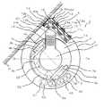
図8は、実施の形態1に係る自走式掃除機の、図1に記載されたDa−Db線での、断面図を示す図である。
図5、8に示すように、回転ブラシ軸13a、13bは、それぞれ直角部4の先端側に延び、その先端にかさ歯ギヤ49a、49bが設けられる。かさ歯ギヤ49a、49bは、互いのギヤ部が歯合するように直交している。また、回転ブラシ12aの上部には、回転ブラシモーター50が設けられる。回転ブラシモーター50の回転軸には、ひら歯ギヤ51とかさ歯ギヤ52が設けられる。ひら歯ギヤ51は、伝達ギヤ53を介して、回転ブラシ軸13の延長上に配置されたひら歯ギヤ54に回転ブラシモーター50の回転力を伝達する。The structure of each drive system of the self-propelled cleaner according to the first embodiment will be described below.
(Rotating brush drive system)
FIG. 8 is a cross-sectional view of the self-propelled cleaner according to the first embodiment, taken along line Da-Db shown in FIG. 1.
As shown in FIGS. 5 and 8, the rotating
回転ブラシモーター50が回転すると、ひら歯ギヤ54に回転力が伝達され、回転ブラシ軸13aが回転する。回転ブラシ軸13aに取り付けられた回転ブラシ12aは、毛ブラシ15が床面Fに接触する際に本体1の外側から中心側に向かう方向に回転する。そして、回転ブラシ軸13aの回転によりかさ歯ギヤ49aが回転すると、歯合するかさ歯ギヤ49bが回転し、回転ブラシ軸13bが回転する。つまり、回転ブラシ軸13aと回転ブラシ軸13bは同期して回転する。回転ブラシ軸13bに取り付けられた回転ブラシ12bは、回転ブラシ12aと同様に、毛ブラシ15が床面Fに接触する際に本体1の外側から本体1の中心側に向かう方向に回転する。 When the
先端ブラシ軸18には、かさ歯ギヤ55が設けられる。かさ歯ギヤ55は、かさ歯ギヤ52に歯合するように直交して配置される。回転ブラシモーター50の回転によってかさ歯ギヤ52が回転すると、歯合するかさ歯ギヤ55が回転する。これにより、先端ブラシ軸18が回転し、先端ブラシ17が床面Fに対して時計回りに水平回転する。 A
(外殻部の駆動系)
図4、5に示すように、外殻部3は、中央部2に対して回転可能に連結される。中央部2は、外殻部3の内部に配置され、外殻部3との連結部には複数の円柱状の転がり部材56が設けられる。外殻部3の中央部2に対する回転可能角度は、90°であり、外殻部3は、中央部2の周りを、図5に示す状態に対して時計回り、反時計回りにそれぞれ45°の範囲で回転する。(Outer shell drive system)
As shown in FIGS. 4 and 5, the
円弧部5の後方部には、角度調節モーター57と角度調節モーター57の回転力を伝達するピニオンギヤ58が設けられる。中央部2には、ラックギヤ59が設けられる。ラックギヤ59は、ピニオンギヤ58と歯合し、角度調節モーター57の回転力がピニオンギヤ58を介して伝達される。制御部(図示せず)は、本体1の動作中に、角度調節モーター57を回転させることにより外殻部3を中央部2に対して回転させる。 An
円弧部5には、ラックギヤ59の位置を検知して、外殻部3の回転角度を検知する角度検知センサー(図示せず)が設けられる。制御部(図示せず)は、角度検知センサーの信号によって外殻部3の回転角度を制御する。 The
図9は、実施の形態1に係る自走式掃除機の、集塵部カバー33等を取り外した状態での、一部断面を含む平面図を示す図であり、図5に示す状態から外殻部3が中央部2に対して反時計回りに45°回転した状態を示す図である。
図5に示す状態において、制御部(図示せず)が角度調節モーター57を反時計回りに回転させると、ピニオンギヤ58は、反時計回りに回転し、歯合するラックギヤ59のギヤ部を転がりながらラックギヤ59の右方向に移動する。ピニオンギヤ58の移動に伴い、角度調節モーター57の固定されている外殻部3は、中央部2に対して反時計回りに回転する。そして、外殻部3が中央部2に対して反時計回りに45°回転すると、角度検知センサー(図示せず)がこれを検知し、制御部(図示せず)に信号を出力する。制御部(図示せず)は、その信号を受けて角度調節モーター57を停止する。FIG. 9 is a diagram showing a plan view including a partial cross section of the self-propelled cleaner according to the first embodiment with the dust collecting
In the state shown in FIG. 5, when a control unit (not shown) rotates the
このとき、駆動輪6a、6bの軸Ga−Gbは、回転ブラシ軸13bに対して直角になる。この状態にすることにより、左側面24bを壁面Hに接触させることができ、回転ブラシ12bを回転させながら壁面Hに沿って本体1を移動させることで、壁際の床面Fを連続的に掃除することが可能である。また、回転ブラシ12aが本体1の移動方向に対して直角であるため、壁面Hから回転ブラシ12aの幅に相当する領域も同時に掃除することができ、壁際の床面Fの掃除の効率をより向上することが可能である。 At this time, the axis Ga-Gb of the
図10は、実施の形態1に係る自走式掃除機の、集塵部カバー33等を取り外した状態での、一部断面を含む平面図を示す図であり、図5に示す状態から外殻部3が中央部2に対して時計回りに45°回転した状態を示す図である。
図5に示す状態において、制御部(図示せず)が角度調節モーター57を時計回りに回転させると、ピニオンギヤ58は、時計回りに回転し、歯合するラックギヤ59のギヤ部を転がりながらラックギヤ59の左方向に移動する。ピニオンギヤ58の移動に伴い、角度調節モーター57の固定されている外殻部3は、中央部2に対して時計回りに回転する。そして、外殻部3が中央部2に対して時計回りに45°回転すると、角度検知センサー(図示せず)がこれを検知し、制御部(図示せず)に信号を出力する。制御部(図示せず)は、その信号を受けて角度調節モーター57を停止する。FIG. 10 is a diagram showing a plan view including a partial cross section of the self-propelled cleaner according to the first embodiment with the dust collecting
In the state shown in FIG. 5, when the control unit (not shown) rotates the
このとき、駆動輪6a、6bの中心軸Ga−Gbは、回転ブラシ軸13aに対して直角になる。この状態にすることにより、右側面24aを壁面Iに接触させることができ、回転ブラシ12aを回転させながら壁面Iに沿って本体1を移動させることで、壁際の床面Fを連続的に掃除することが可能である。また、回転ブラシ12bが本体1の移動方向に対して直角であるため、壁面Iから回転ブラシ12bの幅に相当する領域も同時に掃除することができ、壁際の床面Fの掃除の効率をより向上することが可能である。 At this time, the central axis Ga-Gb of the
図11は、実施の形態1に係る自走式掃除機の、壁面に接触又は近接している状態での、図1に記載されたEa−Eb線での、断面図を示す図である。
図11に示すように、本体1の右側面24aは、壁面Iに接する。回転ブラシ12aの毛ブラシ15が右側面24aの外側に突出するように、回転ブラシ軸13aの位置と毛ブラシ15の長さが設定される。また、右側面24aが壁面Iに接する状態において、毛ブラシ15は、床面Fの隅部に達する。このように構成することにより、壁際まで確実に掃除することができる。FIG. 11 is a cross-sectional view of the self-propelled cleaner according to the first embodiment, taken along line Ea-Eb described in FIG. 1, in a state where the self-propelled cleaner is in contact with or close to the wall surface.
As shown in FIG. 11, the
(駆動輪の駆動系)
図4、5に示すように、一対の駆動輪6a、6bには、それぞれ駆動輪モーター8a、8bがギヤ部9a、9bを介して連結され、一体化した駆動部ユニットが構成される。一対の駆動輪6a、6bは、本体後方側に設けられたヒンジ部(図示せず)を支点に回転可能に支持される。この駆動部ユニットは、バネ(図示せず)により、駆動輪6a、6bを駆動輪開口部7a、7bから突出する方向に力を受ける。本体1が床面Fから持ち上げられると、駆動部ユニットはバネにより力を受けるため、駆動輪開口部7a、7bからの駆動輪6a、6bの突出量が増加する。(Driving system of driving wheels)
As shown in FIGS. 4 and 5,
各駆動輪ユニットには、変位を検知する駆動輪接地センサー(図示せず)が設けられる。制御部(図示せず)は、駆動輪接地センサーの出力を監視することにより、駆動輪6a、6bと床面Fの接触状態を認識する。 Each drive wheel unit is provided with a drive wheel ground sensor (not shown) that detects displacement. The control unit (not shown) recognizes the contact state between the
以下に、実施の形態1に係る自走式掃除機の直角部の動作を説明する。
(直角部の動作)
図4に示すように、直角部4は、外殻部3に上下移動可能に支持される。外殻部3には複数のガイド60が設けられ、直角部4は、ガイド60に沿って上下移動する。また、直角部4は、底面先端部に傾斜面を有し、凸状段差にさしかかった際には、傾斜面が凸状段差により力を受けて、直角部4を上方向に移動する。Below, operation | movement of the right-angled part of the self-propelled cleaner which concerns on
(Operation of right angle part)
As shown in FIG. 4, the
直角部4の後方には、直角部4の上下方向の変位量を検知する変位量検知センサー61が設けられる。変位量検知センサー61は、赤外線の発光部と受光部とで構成される。制御部(図示せず)は、境界部に出射された赤外線の反射光を受光部で検知することにより、直角部4の変位を検出する。制御部(図示せず)は、直角部4が凸状段差に乗り上げたときは、これを乗り越えるように駆動輪6a、6bを制御する。また、凹状段差に落ちたときは、駆動輪6a、6bを停止した後に反転させて、凹状段差からの脱出動作を行うように制御する。 A displacement
図12は、実施の形態1に係る自走式掃除機の、絨毯上を移動する状態での、図1に記載されたBa−Bb線での、断面図を示す図である。
図12に示すように、本体1が柔らかい毛が植毛された絨毯J上を移動すると、駆動輪6a、6bと従動輪10は、本体1の重量を狭い接触面積によって支持するため、絨毯Jの中に沈み込む。一方、直角部4は、絨毯Jとの接触面積が広いため、絨毯Jに沈み込まず、絨毯Jの表面に接して安定する。このように、本体1が絨毯J上を移動すると、直角部4は、駆動輪6a、6b及び外殻部3に対して上方向に移動する。このような構成により、絨毯J上を移動する状態でも絨毯J上の塵埃を掃除することができる。また、塵埃吸込口に回転ブラシ12a、12bが設けられているため、毛ブラシ15が絨毯Jの内部に侵入し、絨毯Jの内部に入り込んだ塵埃も掻き出して掃除することができる。12 is a diagram illustrating a cross-sectional view of the self-propelled cleaner according to the first embodiment, taken along the line Ba-Bb illustrated in FIG. 1, in a state of moving on the carpet.
As shown in FIG. 12, when the
以下に、実施の形態1に係る自走式掃除機の動作を説明する。
(自走式掃除機の動作)
図13〜図22は、実施の形態1に係る自走式掃除機の、動作を示す図である。
図13〜図22において、破線は、本体1の動作前の状態を示す。操作者が本体1の掃除動作を設定すると、制御部(図示せず)は、送風機34を動作させて、右吸込口11aと左吸込口11bと中央吸込口20とから吸引を開始する。また、制御部(図示せず)は、回転ブラシモーター50を動作させて、回転ブラシ12a、12bと先端ブラシ17を回転させる。また、制御部(図示せず)は、所定の動作アルゴリズムに基づいて駆動輪モーター8a、8bをそれぞれ駆動して、本体1を移動させる。なお、図13〜図22では、床面Fを上方から見た際に、壁面Lが壁面Kに対して右側にある場合を示しているが、壁面Lが壁面Kに対して左側にある場合でも、同様に動作することが可能である。Hereinafter, the operation of the self-propelled cleaner according to the first embodiment will be described.
(Operation of self-propelled vacuum cleaner)
13-22 is a figure which shows operation | movement of the self-propelled cleaner which concerns on
13 to 22, a broken line indicates a state before the operation of the
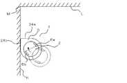
図13は、本体1が壁面Kに向かって斜めに移動する状態を示す。この時点では、本体1は壁面Kから30cm程度離れた位置にあり、右側面近接センサー25a、26aと左側面近接センサー25b、26bは、壁面Kへの近接を検知しない。各近接センサーは、壁面Kとの距離が20cm以下である場合に近接を検知するように設定すると良い。 FIG. 13 shows a state in which the
図14は、本体1が直進し、壁面Kに10cm程度まで近接した状態を示す。このとき、前側の左側面近接センサー25bと後側の左側面近接センサー26bと前側の右側面近接センサー25aが、壁面Kへの近接を検知する。制御部(図示せず)は、これら3つの近接センサーの信号から、前側の左側面近接センサー25bが最も近接していることを認識する。また、制御部(図示せず)は、前側の左側面近接センサー25bと後側の左側面近接センサー26bの距離出力の差から、左側面24bが壁面Kに対して傾斜していることを認識する。 FIG. 14 shows a state in which the
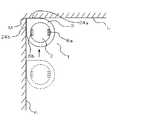
図15は、本体1が左側面24bを壁面Kに接触させた状態を示す。制御部(図示せず)は、図14の時点で左側面24bが壁面Kに対して傾斜していることを認識した後、本体1を右方向に旋回しつつ移動しながら、前側の左側面近接センサー25bと後側の左側面近接センサー26bの距離出力を比較する。そして、制御部(図示せず)は、両近接センサーの距離出力の差が0で且つ両近接センサーが接触を検知するように駆動輪6a、6bを転動させて、左側面24bを壁面Kに接触させる。このとき、左側の回転ブラシ12bは、壁際の床面Fに毛ブラシ15を接触させて、壁際の床面Fの塵埃を掻き出す。そして、塵埃は、左吸込口11bより吸引される。 FIG. 15 shows a state in which the
図16は、駆動輪6a、6bの転動方向を壁面Kに対して平行にした状態を示す。制御部(図示せず)は、図15の状態、つまり左側面24bが壁面Kに接触した状態で、本体1を壁面Kに沿って移動するために、駆動輪6a、6bの転動方向が壁面Kに対して平行になるように、中央部2と外殻部3を回転させる。 FIG. 16 shows a state in which the rolling directions of the
このとき、制御部(図示せず)は、右側の駆動輪6aを負方向に転動(後退方向に転動)し、左側の駆動輪6bを正方向に転動(前進方向に転動)することで、中央部2を時計回りに信地回転する。また、それと同時に、角度調節モーター57を反時計回りに回転して、外殻部3を中央部2に対して反時計回りに回転する。ここで、中央部2の信地回転の速度と外殻部3の回転の速度を同一にすることにより、左側面24bが壁面Kと接触しながら、駆動輪6a、6bの転動方向を変更することができる。 At this time, the control unit (not shown) rolls the
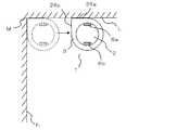
図17は、本体1が壁面K沿いを移動して隅部Mに到達した状態を示す。制御部(図示せず)は、図16の状態、つまり、左側面24bが壁面Kに接触し且つ駆動輪6a、6bの転動方向が壁面Kに対して平行の状態で、駆動輪6a、6bを転動する。本体1は、左側面24bを壁面Kに接触させながら、壁面Kに沿って移動する。このように移動することで、本体1は、壁際の床面Fの塵埃を掻き出して捕集することができる。 FIG. 17 shows a state in which the
本体1が壁面Lに近接すると、前側の右側面近接センサー25aと後側の右側面近接センサー26aが同時に、壁面Lへの近接を検知する。このとき、制御部(図示せず)は、前側の右側面近接センサー25aと後側の右側面近接センサー26aの距離出力を比較することにより、右側面24aの壁面Lに対する角度を認識する。制御部(図示せず)は、両近接センサーが、同じ距離出力である場合は、壁面Lが壁面Kに対して直角であると認識することができる。壁面Lが壁面Kに対して直角でないと認識した場合は、制御部(図示せず)は、掃除漏れが発生する可能性があることを警告する信号を出力する。また、壁面Kと壁面Lの角度に応じた動作アルゴリズムに切り替えて、掃除を続行する。 When the
本体1が隅部Mに到達すると、制御部(図示せず)は、右側面24aを壁面Lに接触させた状態で駆動輪6a、6bの駆動を停止する。そして、所定時間隅部Mに留まって、回転ブラシ12a、12bと先端ブラシ17を回転させ、隅部Mを掃除する。このとき、壁面K側の塵埃は、回転ブラシ12bによって掻き出され、左吸込口11bより吸引される。また、壁面L側の塵埃は、回転ブラシ12aによって掻き出され、右吸込口11aより吸引される。また、壁面Kと壁面Lで形成される隅部に堆積した塵埃は、先端ブラシ17によって掻き出され、右吸込口11aと左吸込口11bと中央吸込口20とより吸引される。 When the
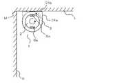
図18は、駆動輪6a、6bの転動方向を壁面Lに対して平行にした状態を示す。制御部(図示せず)は、右側面24aが壁面Lに接触した状態で、本体1を壁面Lに沿って移動するために、駆動輪6a、6bの転動方向が壁面Lに対して平行になるように、中央部2と外殻部3を回転する。 FIG. 18 shows a state in which the rolling directions of the
このとき、制御部(図示せず)は、右側の駆動輪6aを正方向に転動(前進方向に転動)し、左側の駆動輪6’を負方向に転動(後退方向に転動)することで、中央部2を反時計回りに信地回転する。また、それと同時に、角度調節モーター57を時計回りに回転して、外殻部3を中央部2に対して時計回りに回転する。ここで、中央部2の信地回転の速度と外殻部3の回転の速度を同一にすることにより、右側面24aが壁面Lと接触しながら、駆動輪6a、6bの転動方向を変更することができる。つまり、本体1を隅部Mに留めた状態で、駆動輪6a、6bの転動方向を壁面K沿いから壁面L沿いに変更することができる。 At this time, the control unit (not shown) rolls the
図19は、本体1が壁面L沿いを隅部Mから遠ざかる方向に移動した状態を示す。制御部(図示せず)は、図18の状態、つまり、右側面24aが壁面Lに接触し且つ駆動輪6a、6bの転動方向が壁面Lに対して平行の状態で、駆動輪6a、6bを転動する。本体1は、右側面24aを壁面Lに接触させながら、壁面Lに沿って移動する。このように移動することで、本体1は、壁際の床面Fの塵埃を掻き出して捕集することができる。このとき、回転ブラシ12a、12bは、駆動輪6a、6bに対して後方に位置するため、駆動輪6a、6bは、掃除の済んでいない床面を移動することになる。そこで、制御部(図示せず)は、本体1を隅部Mから約50cm程度壁面Lに沿って移動させた後に一時停止し、以下の手順で、回転ブラシ12a、12bが駆動輪6a、6bに対して前方に位置するように、回転ブラシ12a、12bと駆動輪6a、6bの位置関係を変更する。 FIG. 19 shows a state in which the
図20は、本体1が壁面L沿いを移動して隅部M側に戻った状態を示す。制御部(図示せず)は、図19の状態において、左側の回転ブラシ12bが掃除した範囲を外殻部3が十分通過する位置まで、本体1を隅部M側に向けて移動する。これは、次に行う回転ブラシ12a、12bと駆動輪6a、6bの位置関係の変更によって掃除漏れとなる床面Fが発生することを防止するための動作である。 FIG. 20 shows a state in which the
図21は、回転ブラシ12a、12bが駆動輪6a、6bに対して前方に位置するように、回転ブラシ12a、12bと駆動輪6a、6bの位置関係を変更した状態を示す。制御部(図示せず)は、図20の状態、つまり、外殻部3が中央部2に対して時計回りに45°回転した状態から、外殻部3が中央部2に対して反時計回りに45°回転した状態になるまで、外殻部3を回転する。また、それと同時に、右側の駆動輪6aを正方向に転動(前進方向に転動)し、左側の駆動輪6bを負方向に転動(後退方向に転動)することで、中央部2を反時計回りに180°信地回転する。この動作により、図20における本体1の位置する場所と同じ場所で、回転ブラシ12a、12bを駆動輪6a、6bよりも前側、つまり隅部Mから遠ざかる側に配置することができる。また、壁面L沿いを更に移動した後に現れる次の隅部での掃除に対応することができる。なお、外殻部3の回転と中央部2の信地回転は、同時でなくても構わないが、同時である方が回転ブラシ12a、12bと駆動輪6a、6bの位置関係の変更に要する時間を節約できるため好ましい。 FIG. 21 shows a state in which the positional relationship between the
図22は、本体1が壁面L沿いを隅部Mから遠ざかる方向に移動した状態を示す。制御部(図示せず)は、図21の状態、つまり、左側面24bが壁面Lに接触し且つ駆動輪6a、6bの転動方向が壁面Lに対して平行の状態で、駆動輪6a、6bを転動する。本体1は、左側面24bを壁面Lに接触させながら、壁面Lに沿って隅部Mから遠ざかる方向に移動する。このように移動することで、本体1は、壁際の床面Fの塵埃を掻き出して捕集することができる。 FIG. 22 shows a state in which the
なお、実施の形態1に係る自走式掃除機は、壁際の床面Fを掃除する際に、右側面24aや左側面24bを壁面に接触させるように動作させているが、壁面から数mm離して極近接させた状態で動作させても良い。このように動作させることにより、壁面に傷をつけることなく壁際の床面Fを掃除することができる。 The self-propelled cleaner according to the first embodiment is operated so that the
また、右側面24aと左側面24bのそれぞれに、フッ素樹脂等の素材で構成された滑り性能の高い緩衝部材を設けても良い。このように構成することにより、右側面24aと左側面24bを壁面に接触させた際に、壁面に傷をつけることを防止することができる。 Moreover, you may provide the buffer member with high sliding performance comprised with raw materials, such as a fluororesin, in each of the
また、実施の形態1に係る自走式掃除機は、外殻部の直角部に複数の塵埃吸込口を備えたものであるが、このような形態に限定されない。例えば、外殻部に塵埃吸込口を1つ備えたものでも、実施の形態1に係る自走式掃除機と同様の効果を得られることは、言うまでもない。実施の形態1に係る自走式掃除機のように、外殻部3に壁面と平行な側面を備えたり隅部の床面の壁面交差角度に応じた角部を備えたりすることで、壁際の床面や隅部の床面に吸込口を近接することができるため、掃除漏れを更に少なくすることが可能となる。また、実施の形態1に係る自走式掃除機のように、長手方向が互いに異なる複数の塵埃吸込口を備えたことで、複数箇所を同時に掃除することができるため、掃除効率を更に向上することが可能となる。 In addition, the self-propelled cleaner according to the first embodiment includes a plurality of dust suction ports at right angles of the outer shell, but is not limited to such a form. For example, it goes without saying that the same effect as that of the self-propelled cleaner according to the first embodiment can be obtained even if the outer shell portion has one dust suction port. Like the self-propelled cleaner according to the first embodiment, the
また、実施の形態1に係る自走式掃除機は、外殻部が中央部に対して±45°の範囲で回転するものであるが、このような形態に限定されない。例えば、外殻部を中央部に対して360°回転するものでも、実施の形態1に係る自走式掃除機と同様の効果を得られることは、言うまでもない。実施の形態1に係る自走式掃除機のように、外殻部が回転する範囲を制限することで、集塵部の後方に蓄電池等を設けることができ、自走式掃除機を小型化することが可能となる。 Further, the self-propelled cleaner according to the first embodiment is such that the outer shell portion rotates within a range of ± 45 ° with respect to the central portion, but is not limited to such a form. For example, it goes without saying that the same effect as that of the self-propelled cleaner according to the first embodiment can be obtained even when the outer shell portion is rotated 360 ° with respect to the central portion. Like the self-propelled cleaner according to the first embodiment, by limiting the range in which the outer shell portion rotates, a storage battery or the like can be provided behind the dust collecting portion, and the self-propelled cleaner is downsized. It becomes possible to do.
また、実施の形態1に係る自走式掃除機は、中央部の回転中心を通る直線上に2つの駆動輪を備えたものであるが、このような形態に限定されない。例えば、中央部を移動する駆動輪とは別に中央部を信地回転する機構を備えたものでも、実施の形態1に係る自走式掃除機と同様の効果を得られることは、言うまでもない。実施の形態1に係る自走式掃除機のように、中央部の回転中心を通る直線上に2つの駆動輪を備えたことで、中央部を移動する機構と中央部を信地回転する機構を兼用することができ、自走式掃除機を小型化することが可能となる。 In addition, the self-propelled cleaner according to the first embodiment includes two drive wheels on a straight line passing through the center of rotation at the center, but is not limited to such a form. For example, it is needless to say that the same effect as that of the self-propelled cleaner according to the first embodiment can be obtained even if a mechanism that rotates the central part apart from the drive wheel that moves in the central part is provided. Like the self-propelled cleaner according to the first embodiment, a mechanism for moving the central portion and a mechanism for rotating the central portion by providing two drive wheels on a straight line passing through the rotation center of the central portion The self-propelled cleaner can be reduced in size.
また、実施の形態1に係る自走式掃除機は、塵埃吸込口に回転ブラシと塵埃受けとを備えたものであるが、このような形態に限定されない。例えば、塵埃吸込口に何も備えなかったり、回転ブラシと塵埃受けのどちらか一方だけを備えたり、他の部材を備えたものでも、実施の形態1と同様の効果を得られることは、言うまでもない。実施の形態1に係る自走式掃除機のように、塵埃吸込口に回転ブラシと塵埃受けを備えることで、床面の塵埃、特に壁際の床面の塵埃を確実に掃除できるため、掃除漏れを更に少なくすることが可能となる。また、実施の形態1に係る自走式掃除機のように、塵埃吸込口に回転ブラシを備えることで、絨毯上も掃除することができ、掃除漏れを更に少なくすることが可能となる。 In addition, the self-propelled cleaner according to the first embodiment is provided with a rotating brush and a dust receiver at the dust suction port, but is not limited to such a form. For example, it is needless to say that the same effect as that of the first embodiment can be obtained even if the dust suction port has nothing, only one of the rotating brush and the dust receiver, or other members. Yes. As in the self-propelled cleaner according to the first embodiment, by providing the dust suction port with the rotating brush and the dust receiver, the dust on the floor surface, particularly the dust on the floor surface near the wall can be reliably cleaned. Can be further reduced. Further, as in the self-propelled cleaner according to the first embodiment, by providing the dust suction port with the rotating brush, the carpet can be cleaned, and cleaning leakage can be further reduced.
また、実施の形態1に係る自走式掃除機は、直角部が外殻部に上下移動可能に支持されるものであるが、このような形態に限定されない。例えば、直角部を固定したり、直角部の底面を前方が高くなるように傾斜させたものでも、実施の形態1と同様の効果を得られることは、言うまでもない。実施の形態1に係る自走式掃除機のように、直角部を上下移動することで、確実に凸状段差を乗り越えることが可能となる。また、実施の形態1に係る自走式掃除機のように、直角部を上下移動することで、絨毯上も掃除することができ、掃除漏れを更に少なくすることが可能となる。 Further, the self-propelled cleaner according to the first embodiment is supported by the right-angled portion so as to be vertically movable on the outer shell portion, but is not limited to such a configuration. For example, it goes without saying that the same effect as in the first embodiment can be obtained even when the right-angled portion is fixed or the bottom surface of the right-angled portion is inclined so that the front becomes higher. Like the self-propelled cleaner according to the first embodiment, it is possible to surely get over the convex step by moving the right-angled portion up and down. Moreover, like the self-propelled cleaner according to the first embodiment, by moving the right-angled portion up and down, it is possible to clean the carpet, and it is possible to further reduce cleaning leakage.
また、実施の形態1に係る自走式掃除機は、先端ブラシ17の毛ブラシ19が、先端ブラシ軸18の下端部に植毛された長さの異なる3条の毛ブラシで構成されるものであるが、毛ブラシ19が、1条の毛ブラシによって構成されても良い。その場合には、毛ブラシ19が、毛ブラシの先端側が広がるように先端ブラシ軸18の下端部に植毛され、外側の毛ブラシの長さが内側の毛ブラシの長さよりも長くなるように構成されると良い。そのように構成されることで、床面Fの塵埃の掻き取り効果が向上し、髪の毛や糸等が毛ブラシ19に絡みつくことが抑制される。 In addition, the self-propelled cleaner according to the first embodiment is configured such that the
また、実施の形態1に係る自走式掃除機は、本体1の底面に従動輪10を備えるものであるが、従動輪10を備えなくても良い。その場合には、回転ブラシ12a、12bの毛ブラシ15が床面Fに接して本体1の前方を支持するため、本体1は床面Fに対して水平に支持される。
また、従動輪10に代えて摺動性の高いクッション部材を備えても良い。その場合には、本体1の前方が持ち上がった際に、クッション部材が床面Fに当接し、本体1の底面が損傷することが防止される。In addition, the self-propelled cleaner according to the first embodiment includes the driven
Further, instead of the driven
また、実施の形態1に係る自走式掃除機は、送風機34と集塵部37が、シール部材42によって送風機34と集塵部37の間の風路の気密が確保された状態で、水平方向に摺動可能に構成されるものであるが、送風機34と集塵部37の両者が、外殻部3に設けられてもよい。その場合には、外殻部3が中央部2に対して回転する際に、送風機34の排気ダクト36が駆動輪モータ8a、8b等と干渉しないように構成される。 Further, the self-propelled cleaner according to the first embodiment is configured such that the
また、実施の形態1に係る自走式掃除機は、直角部4が、外殻部3に設けられた複数のガイド60に沿って上下移動可能に構成されるものであるが、直角部4が、直角部4の一部を中心にして上下方向に回転可能に構成されても良い。 In addition, the self-propelled cleaner according to the first embodiment is configured such that the
以上のように、実施の形態1に係る自走式掃除機は、駆動輪の転動方向に対する塵埃吸込口の長手方向の角度が最適化されるように塵埃吸込口角度変更手段を制御する制御手段を備えることにより、床面の隅部等の狭い空間に塵埃吸込口を到達することが可能となり、掃除漏れを少なくすることができる。また、実施の形態1に係る自走式掃除機は、駆動輪の転動方向に対する塵埃吸込口の長手方向の角度が最適化されるように塵埃吸込口角度変更手段を制御する制御手段を備えることにより、床面の隅部等の狭い空間を掃除する際に本体の移動方向の転換と前後進を繰り返す必要がなくなり、掃除効率を向上することができる。 As described above, the self-propelled cleaner according to the first embodiment controls the dust suction port angle changing means so that the angle of the dust suction port in the longitudinal direction with respect to the rolling direction of the drive wheel is optimized. By providing the means, it becomes possible to reach the dust suction port into a narrow space such as a corner of the floor surface, and the cleaning leakage can be reduced. Further, the self-propelled cleaner according to the first embodiment includes control means for controlling the dust suction port angle changing means so that the angle of the dust suction port in the longitudinal direction with respect to the rolling direction of the drive wheel is optimized. Accordingly, when cleaning a narrow space such as a corner of the floor surface, it is not necessary to repeat the change of the moving direction of the main body and the forward and backward movement, and the cleaning efficiency can be improved.
1 本体、2 中央部、3 外殻部、4 直角部、5 円弧部、6 駆動輪、10 従動輪、11a 右吸込口、11b 左吸込口、12 回転ブラシ、16 塵埃受け、17 先端ブラシ、20 中央吸込口、21 塵埃受け。 DESCRIPTION OF
Claims (17)
Translated fromJapanese前記本体の内部にあって前記塵埃吸込口から前記床面上の空気を吸引する送風機及び集塵部と、
前記駆動輪と送風機を制御する制御回路を有する電気回路基板と、を備え、
前記本体の外殻形状は、1つの頂部から連続する2つの平面状側面を有し、
前記頂部を通り、前記本体を二等分する中心線を挟んで、その両側の位置に、前記駆動輪をそれぞれ配置し、
前記駆動輪は、その転動方向及び転動量が互いに独立して前記制御回路により制御され、
前記塵埃吸込口は、前記本体の底面において前記2つの平面状側面に沿った方向にそれぞれが細長く形成され、
前記本体には、前記送風機の運転中、前記床面に対して水平、かつ、前記塵埃吸込口の長手方向に沿って配置された軸を中心として回転駆動されて前記床面上を回転する回転ブラシを備え、前記回転ブラシは、その回転中心部が、前記塵埃吸込口の近傍にあって、前記本体の最外殻面よりも外側へ常に突出して回転することを特徴とする自走式掃除機。A main body having a plurality of driving wheels that roll on the floor surface, and a dust suction port provided on the bottom surface;
A blower and a dust collecting unit that sucks air on the floor surface from the dust suction port inside the main body;
An electric circuit board having a control circuit for controlling the driving wheel and the blower,
The outer shell shape of the body has two planar side surfaces continuous from one top,
Passing through the top, sandwiching the center line that bisects the main body, the drive wheels are arranged at positions on both sides thereof,
The driving wheel, the rolling direction and the rolling amount are controlled by the control circuit independently of each other,
Each of the dust suction ports is formed in an elongated shape in the direction along the two planar side surfaces on the bottom surface of the main body,
The main body is rotated while rotating on the floor surface while being driven by the rotation centering on an axis disposed along the longitudinal direction of the dust suction port and horizontal to the floor surface during operation of the blower. A self-propelled cleaning device comprising: a brush, wherein the rotating brush has a rotation center portion in the vicinity of the dust suction port, and always protrudes and rotates outward from the outermost shell surface of the main body. Machine.
前記駆動輪を有し、前記駆動輪の転動により移動及び信地回転可能な中央部と、
前記塵埃吸込口を有し、前記中央部に前記中央部の周りを回転可能に保持される外殻部と、を有する、
ことを特徴とする請求項1に記載の自走式掃除機。The outer shell shape of the main body is
A central portion having the drive wheel, and movable and pivotable by rolling of the drive wheel;
An outer shell portion that has the dust suction port and is rotatably held around the center portion in the center portion;
The self-propelled cleaner according to claim 1.
前記塵埃吸込口は、長手方向が前記平面状側面と平行又は直角になるように形成される、
ことを特徴とする請求項2に記載の自走式掃除機。The outer shell portion has a planar side surface;
The dust suction port is formed so that the longitudinal direction is parallel or perpendicular to the planar side surface,
The self-propelled cleaner according to claim 2.
ことを特徴とする請求項3に記載の自走式掃除機。The outer shell portion has two planar side surfaces so as to cross each other, and a first dust suction port is formed so that a longitudinal direction is parallel to one of the two planar side surfaces, The second dust suction port is formed so that the longitudinal direction is parallel to the other of the two planar side surfaces,
The self-propelled cleaner according to claim 3.
前記第3塵埃吸込口は、長手方向が前記2つの平面状側面と同一角度で交差するように形成される、
ことを特徴とする請求項4に記載の自走式掃除機。The outer shell portion has a third dust suction port between the first dust suction port and the second dust suction port,
The third dust suction port is formed such that the longitudinal direction intersects with the two planar side surfaces at the same angle.
The self-propelled cleaner according to claim 4.
ことを特徴とする請求項4又は5に記載の自走式掃除機。When the control circuit is not in contact with or close to the wall surface, a top portion formed by the two planar side surfaces is disposed on a center line passing through the center of the main body and parallel to the rolling direction of the drive wheel. The rotation angle of the outer shell portion is set so that the rotation angle of the outer shell portion is set so that the planar side surface is parallel or perpendicular to the wall surface in a state where it is in contact with or close to the wall surface.
The self-propelled cleaner according to claim 4 or 5.
前記制御回路は、前記本体の中心を通り且つ前記駆動輪の転動方向と平行な中心線上に前記頂部を配置した状態に対して±45°の範囲で前記外殻部を回転する、
ことを特徴とする請求項4〜6のいずれか一項に記載の自走式掃除機。The angle of the top formed by the two planar side faces is 90 °;
The control circuit rotates the outer shell portion in a range of ± 45 ° with respect to a state in which the top portion is arranged on a center line passing through the center of the main body and parallel to the rolling direction of the drive wheel.
The self-propelled cleaner as described in any one of Claims 4-6 characterized by the above-mentioned.
前記制御回路は、前記中央部を信地回転し、且つ、前記中央部の信地回転に対して同一速度で逆方向に同一角度だけ前記外殻部を同時に回転して、前記本体の移動方向を転換する、
ことを特徴とする請求項2〜7のいずれか一項に記載の自走式掃除機。The center of rotation of the central part and the center of rotation of the outer shell part are the same,
The control circuit rotates the central part at the same time, and simultaneously rotates the outer shell part by the same angle in the opposite direction at the same speed with respect to the central part of the central part, and the moving direction of the main body Convert
The self-propelled cleaner as described in any one of Claims 2-7 characterized by the above-mentioned.
ことを特徴とする請求項2〜8のいずれか一項に記載の自走式掃除機。The driving wheel is two points on a straight line that passes through the center of rotation of the central part and is perpendicular to the rolling direction of the driving wheel, and is separated from the center of rotation by the same distance in the opposite direction. Placed at two points,
The self-propelled cleaner as described in any one of Claims 2-8 characterized by the above-mentioned.
ことを特徴とする請求項4又は請求項4に従属する請求項5〜9のいずれか一項に記載の自走式掃除機。The first dust suction port and the second dust suction port have a rotating brush,
The self-propelled cleaner according to any one ofclaims 5 to 9, whichis dependent on claim 4 or claim 4 .
ことを特徴とする請求項10に記載の自走式掃除機。The rotating brush protrudes from the outer periphery of the main body,
The self-propelled cleaner according to claim 10.
ことを特徴とする請求項10又は11に記載の自走式掃除機。The rotating brush is driven by one driving source,
The self-propelled cleaner according to claim 10 or 11, characterized in that.
ことを特徴とする請求項1〜12のいずれか一項に記載の自走式掃除機。The dust suction port is movable in the vertical direction with respect to the drive wheel.
The self-propelled cleaner according to any one of claims 1 to 12, wherein
ことを特徴とする請求項1〜13のいずれか一項に記載の自走式掃除機。The dust inlet has a dust receiver,
The self-propelled cleaner according to any one of claims 1 to 13, wherein
ことを特徴とする請求項1〜14のいずれか一項に記載の自走式掃除機。The main body includes a sensor for detecting a distance between the side surface and the wall surface and / or an angle between the side surface and the wall surface.
The self-propelled cleaner as described in any one of Claims 1-14 characterized by the above-mentioned.
ことを特徴とする請求項1〜15のいずれか一項に記載の自走式掃除機。A heat generating member is disposed in the exhaust path of the main body.
The self-propelled cleaner as described in any one of Claims 1-15 characterized by the above-mentioned.
ことを特徴とする請求項1〜16のいずれか一項に記載の自走式掃除機。The main body has a plurality of storage batteries built in along the outer shape of the main body.
The self-propelled cleaner as described in any one of Claims 1-16 characterized by the above-mentioned.
Priority Applications (1)
| Application Number | Priority Date | Filing Date | Title |
|---|---|---|---|
| JP2012122850AJP6071251B2 (en) | 2012-05-30 | 2012-05-30 | Self-propelled vacuum cleaner |
Applications Claiming Priority (1)
| Application Number | Priority Date | Filing Date | Title |
|---|---|---|---|
| JP2012122850AJP6071251B2 (en) | 2012-05-30 | 2012-05-30 | Self-propelled vacuum cleaner |
Related Child Applications (1)
| Application Number | Title | Priority Date | Filing Date |
|---|---|---|---|
| JP2016128927ADivisionJP6195649B2 (en) | 2016-06-29 | 2016-06-29 | Self-propelled vacuum cleaner |
Publications (3)
| Publication Number | Publication Date |
|---|---|
| JP2013247986A JP2013247986A (en) | 2013-12-12 |
| JP2013247986A5 JP2013247986A5 (en) | 2015-07-02 |
| JP6071251B2true JP6071251B2 (en) | 2017-02-01 |
Family
ID=49847330
Family Applications (1)
| Application Number | Title | Priority Date | Filing Date |
|---|---|---|---|
| JP2012122850AExpired - Fee RelatedJP6071251B2 (en) | 2012-05-30 | 2012-05-30 | Self-propelled vacuum cleaner |
Country Status (1)
| Country | Link |
|---|---|
| JP (1) | JP6071251B2 (en) |
Families Citing this family (25)
| Publication number | Priority date | Publication date | Assignee | Title |
|---|---|---|---|---|
| KR102137923B1 (en) | 2013-04-15 | 2020-07-24 | 에이비 엘렉트로룩스 | Robotic vacuum cleaner with protruding sidebrush |
| WO2014169943A1 (en) | 2013-04-15 | 2014-10-23 | Aktiebolaget Electrolux | Robotic vacuum cleaner |
| US10433697B2 (en) | 2013-12-19 | 2019-10-08 | Aktiebolaget Electrolux | Adaptive speed control of rotating side brush |
| US10209080B2 (en) | 2013-12-19 | 2019-02-19 | Aktiebolaget Electrolux | Robotic cleaning device |
| US10617271B2 (en) | 2013-12-19 | 2020-04-14 | Aktiebolaget Electrolux | Robotic cleaning device and method for landmark recognition |
| WO2015090439A1 (en) | 2013-12-20 | 2015-06-25 | Aktiebolaget Electrolux | Dust container |
| CN105813527A (en)* | 2013-12-20 | 2016-07-27 | 伊莱克斯公司 | Autonomous cleaner |
| CN106535729A (en)* | 2014-06-30 | 2017-03-22 | 松下知识产权经营株式会社 | Autonomous travel-type cleaner |
| US10499778B2 (en) | 2014-09-08 | 2019-12-10 | Aktiebolaget Electrolux | Robotic vacuum cleaner |
| EP3190938A1 (en) | 2014-09-08 | 2017-07-19 | Aktiebolaget Electrolux | Robotic vacuum cleaner |
| EP3230814B1 (en) | 2014-12-10 | 2021-02-17 | Aktiebolaget Electrolux | Using laser sensor for floor type detection |
| CN107072454A (en) | 2014-12-12 | 2017-08-18 | 伊莱克斯公司 | Side brushes and robot vacuums |
| EP3234713B1 (en) | 2014-12-16 | 2022-06-15 | Aktiebolaget Electrolux | Cleaning method for a robotic cleaning device |
| CN107003669B (en) | 2014-12-16 | 2023-01-31 | 伊莱克斯公司 | Experience-Based Roadmap for Robotic Cleaning Equipment |
| US11099554B2 (en) | 2015-04-17 | 2021-08-24 | Aktiebolaget Electrolux | Robotic cleaning device and a method of controlling the robotic cleaning device |
| EP3344104B1 (en) | 2015-09-03 | 2020-12-30 | Aktiebolaget Electrolux | System of robotic cleaning devices |
| WO2017157421A1 (en) | 2016-03-15 | 2017-09-21 | Aktiebolaget Electrolux | Robotic cleaning device and a method at the robotic cleaning device of performing cliff detection |
| US11122953B2 (en) | 2016-05-11 | 2021-09-21 | Aktiebolaget Electrolux | Robotic cleaning device |
| EP3629869B1 (en) | 2017-06-02 | 2023-08-16 | Aktiebolaget Electrolux | Method of detecting a difference in level of a surface in front of a robotic cleaning device |
| EP3687357B1 (en) | 2017-09-26 | 2024-07-10 | Aktiebolaget Electrolux | Controlling movement of a robotic cleaning device |
| CN107638140A (en)* | 2017-11-09 | 2018-01-30 | 桂暄皓 | All-in-one is dragged in a kind of automatic brush |
| KR102070282B1 (en) | 2018-04-30 | 2020-01-28 | 엘지전자 주식회사 | Cleaner and controlling method thereof |
| KR102122237B1 (en)* | 2018-04-30 | 2020-06-15 | 엘지전자 주식회사 | Cleaner and controlling method thereof |
| JP7160726B2 (en)* | 2019-03-12 | 2022-10-25 | 東芝ライフスタイル株式会社 | Vacuum cleaner and its suction port body |
| JP7492318B2 (en)* | 2019-06-05 | 2024-05-29 | 東芝ライフスタイル株式会社 | Vacuum cleaner |
Family Cites Families (8)
| Publication number | Priority date | Publication date | Assignee | Title |
|---|---|---|---|---|
| JPH0732751B2 (en)* | 1986-06-12 | 1995-04-12 | 松下電器産業株式会社 | Self-propelled vacuum cleaner |
| JPH07319542A (en)* | 1994-05-30 | 1995-12-08 | Minolta Co Ltd | Self-traveling work wagon |
| JP2005211368A (en)* | 2004-01-30 | 2005-08-11 | Funai Electric Co Ltd | Self-propelled cleaner |
| JP2005230044A (en)* | 2004-02-17 | 2005-09-02 | Funai Electric Co Ltd | Autonomous running robot cleaner |
| CN100586356C (en)* | 2005-07-08 | 2010-02-03 | 伊莱克斯公司 | robot cleaning equipment |
| EP2270619B1 (en)* | 2005-12-02 | 2013-05-08 | iRobot Corporation | Modular robot |
| JP5512225B2 (en)* | 2009-07-31 | 2014-06-04 | Cyberdyne株式会社 | Self-propelled cleaning robot with side brush device |
| EP2420169A1 (en)* | 2010-08-19 | 2012-02-22 | Koninklijke Philips Electronics N.V. | Cleaning device as well as a method to control a cleaning device |
- 2012
- 2012-05-30JPJP2012122850Apatent/JP6071251B2/ennot_activeExpired - Fee Related
Also Published As
| Publication number | Publication date |
|---|---|
| JP2013247986A (en) | 2013-12-12 |
Similar Documents
| Publication | Publication Date | Title |
|---|---|---|
| JP6071251B2 (en) | Self-propelled vacuum cleaner | |
| JP6195649B2 (en) | Self-propelled vacuum cleaner | |
| JP6120695B2 (en) | Dust collector, vacuum cleaner, self-propelled cleaner, and system including self-propelled cleaner and charging stand | |
| CN103027633B (en) | Robot cleaner | |
| KR101907161B1 (en) | Robot cleaner | |
| KR102137524B1 (en) | Robot cleaner | |
| KR101249864B1 (en) | Robot cleaner | |
| JP2014028034A (en) | Cleaner and self-propelled cleaner | |
| JP5968100B2 (en) | Self-propelled vacuum cleaner | |
| JP6800214B2 (en) | Robot vacuum cleaner | |
| CN106793903B (en) | Robot cleaner | |
| WO2019044074A1 (en) | Autonomous cleaner | |
| CA2955650C (en) | Vacuum cleaner | |
| JP2014018620A (en) | Self-propelled vacuum cleaner | |
| JP7065275B2 (en) | Autonomous vacuum cleaner | |
| JP5892098B2 (en) | Self-propelled vacuum cleaner | |
| JP6105886B2 (en) | Suction port and vacuum cleaner | |
| JP2011177214A (en) | Floor suction tool of vacuum cleaner | |
| KR101450972B1 (en) | Automatic cleaner | |
| JP2014204891A (en) | Self-propelled vacuum cleaner | |
| KR100677259B1 (en) | Brush device of robot cleaner | |
| JP2018082988A (en) | Vacuum cleaner | |
| JP5388782B2 (en) | Suction port and vacuum cleaner | |
| KR100619727B1 (en) | Robot Cleaner Driving Device | |
| JP2025082828A (en) | Suction tool and vacuum cleaner |
Legal Events
| Date | Code | Title | Description |
|---|---|---|---|
| A521 | Request for written amendment filed | Free format text:JAPANESE INTERMEDIATE CODE: A523 Effective date:20150515 | |
| A621 | Written request for application examination | Free format text:JAPANESE INTERMEDIATE CODE: A621 Effective date:20150515 | |
| A977 | Report on retrieval | Free format text:JAPANESE INTERMEDIATE CODE: A971007 Effective date:20151120 | |
| A131 | Notification of reasons for refusal | Free format text:JAPANESE INTERMEDIATE CODE: A131 Effective date:20151201 | |
| A02 | Decision of refusal | Free format text:JAPANESE INTERMEDIATE CODE: A02 Effective date:20160329 | |
| A521 | Request for written amendment filed | Free format text:JAPANESE INTERMEDIATE CODE: A523 Effective date:20160629 | |
| A911 | Transfer to examiner for re-examination before appeal (zenchi) | Free format text:JAPANESE INTERMEDIATE CODE: A911 Effective date:20160707 | |
| A131 | Notification of reasons for refusal | Free format text:JAPANESE INTERMEDIATE CODE: A131 Effective date:20161004 | |
| A521 | Request for written amendment filed | Free format text:JAPANESE INTERMEDIATE CODE: A523 Effective date:20161122 | |
| TRDD | Decision of grant or rejection written | ||
| A01 | Written decision to grant a patent or to grant a registration (utility model) | Free format text:JAPANESE INTERMEDIATE CODE: A01 Effective date:20161220 | |
| A61 | First payment of annual fees (during grant procedure) | Free format text:JAPANESE INTERMEDIATE CODE: A61 Effective date:20161227 | |
| R150 | Certificate of patent or registration of utility model | Ref document number:6071251 Country of ref document:JP Free format text:JAPANESE INTERMEDIATE CODE: R150 | |
| R250 | Receipt of annual fees | Free format text:JAPANESE INTERMEDIATE CODE: R250 | |
| R250 | Receipt of annual fees | Free format text:JAPANESE INTERMEDIATE CODE: R250 | |
| R250 | Receipt of annual fees | Free format text:JAPANESE INTERMEDIATE CODE: R250 | |
| R250 | Receipt of annual fees | Free format text:JAPANESE INTERMEDIATE CODE: R250 | |
| R250 | Receipt of annual fees | Free format text:JAPANESE INTERMEDIATE CODE: R250 | |
| LAPS | Cancellation because of no payment of annual fees |