JP6070854B2 - Control device for hybrid vehicle - Google Patents
Control device for hybrid vehicleDownload PDFInfo
- Publication number
- JP6070854B2 JP6070854B2JP2015541359AJP2015541359AJP6070854B2JP 6070854 B2JP6070854 B2JP 6070854B2JP 2015541359 AJP2015541359 AJP 2015541359AJP 2015541359 AJP2015541359 AJP 2015541359AJP 6070854 B2JP6070854 B2JP 6070854B2
- Authority
- JP
- Japan
- Prior art keywords
- engine
- mode
- motor
- sound vibration
- control
- Prior art date
- Legal status (The legal status is an assumption and is not a legal conclusion. Google has not performed a legal analysis and makes no representation as to the accuracy of the status listed.)
- Active
Links
Images


Classifications
- B—PERFORMING OPERATIONS; TRANSPORTING
- B60—VEHICLES IN GENERAL
- B60K—ARRANGEMENT OR MOUNTING OF PROPULSION UNITS OR OF TRANSMISSIONS IN VEHICLES; ARRANGEMENT OR MOUNTING OF PLURAL DIVERSE PRIME-MOVERS IN VEHICLES; AUXILIARY DRIVES FOR VEHICLES; INSTRUMENTATION OR DASHBOARDS FOR VEHICLES; ARRANGEMENTS IN CONNECTION WITH COOLING, AIR INTAKE, GAS EXHAUST OR FUEL SUPPLY OF PROPULSION UNITS IN VEHICLES
- B60K6/00—Arrangement or mounting of plural diverse prime-movers for mutual or common propulsion, e.g. hybrid propulsion systems comprising electric motors and internal combustion engines
- B60K6/20—Arrangement or mounting of plural diverse prime-movers for mutual or common propulsion, e.g. hybrid propulsion systems comprising electric motors and internal combustion engines the prime-movers consisting of electric motors and internal combustion engines, e.g. HEVs
- B60K6/50—Architecture of the driveline characterised by arrangement or kind of transmission units
- B60K6/54—Transmission for changing ratio
- B60K6/543—Transmission for changing ratio the transmission being a continuously variable transmission
- B—PERFORMING OPERATIONS; TRANSPORTING
- B60—VEHICLES IN GENERAL
- B60W—CONJOINT CONTROL OF VEHICLE SUB-UNITS OF DIFFERENT TYPE OR DIFFERENT FUNCTION; CONTROL SYSTEMS SPECIALLY ADAPTED FOR HYBRID VEHICLES; ROAD VEHICLE DRIVE CONTROL SYSTEMS FOR PURPOSES NOT RELATED TO THE CONTROL OF A PARTICULAR SUB-UNIT
- B60W10/00—Conjoint control of vehicle sub-units of different type or different function
- B60W10/04—Conjoint control of vehicle sub-units of different type or different function including control of propulsion units
- B60W10/06—Conjoint control of vehicle sub-units of different type or different function including control of propulsion units including control of combustion engines
- B—PERFORMING OPERATIONS; TRANSPORTING
- B60—VEHICLES IN GENERAL
- B60W—CONJOINT CONTROL OF VEHICLE SUB-UNITS OF DIFFERENT TYPE OR DIFFERENT FUNCTION; CONTROL SYSTEMS SPECIALLY ADAPTED FOR HYBRID VEHICLES; ROAD VEHICLE DRIVE CONTROL SYSTEMS FOR PURPOSES NOT RELATED TO THE CONTROL OF A PARTICULAR SUB-UNIT
- B60W10/00—Conjoint control of vehicle sub-units of different type or different function
- B60W10/04—Conjoint control of vehicle sub-units of different type or different function including control of propulsion units
- B60W10/08—Conjoint control of vehicle sub-units of different type or different function including control of propulsion units including control of electric propulsion units, e.g. motors or generators
- B—PERFORMING OPERATIONS; TRANSPORTING
- B60—VEHICLES IN GENERAL
- B60W—CONJOINT CONTROL OF VEHICLE SUB-UNITS OF DIFFERENT TYPE OR DIFFERENT FUNCTION; CONTROL SYSTEMS SPECIALLY ADAPTED FOR HYBRID VEHICLES; ROAD VEHICLE DRIVE CONTROL SYSTEMS FOR PURPOSES NOT RELATED TO THE CONTROL OF A PARTICULAR SUB-UNIT
- B60W20/00—Control systems specially adapted for hybrid vehicles
- B60W20/40—Controlling the engagement or disengagement of prime movers, e.g. for transition between prime movers
- F—MECHANICAL ENGINEERING; LIGHTING; HEATING; WEAPONS; BLASTING
- F02—COMBUSTION ENGINES; HOT-GAS OR COMBUSTION-PRODUCT ENGINE PLANTS
- F02D—CONTROLLING COMBUSTION ENGINES
- F02D41/00—Electrical control of supply of combustible mixture or its constituents
- F02D41/02—Circuit arrangements for generating control signals
- F02D41/04—Introducing corrections for particular operating conditions
- F02D41/06—Introducing corrections for particular operating conditions for engine starting or warming up
- F02D41/062—Introducing corrections for particular operating conditions for engine starting or warming up for starting
- F—MECHANICAL ENGINEERING; LIGHTING; HEATING; WEAPONS; BLASTING
- F02—COMBUSTION ENGINES; HOT-GAS OR COMBUSTION-PRODUCT ENGINE PLANTS
- F02N—STARTING OF COMBUSTION ENGINES; STARTING AIDS FOR SUCH ENGINES, NOT OTHERWISE PROVIDED FOR
- F02N11/00—Starting of engines by means of electric motors
- F02N11/006—Starting of engines by means of electric motors using a plurality of electric motors
- F—MECHANICAL ENGINEERING; LIGHTING; HEATING; WEAPONS; BLASTING
- F02—COMBUSTION ENGINES; HOT-GAS OR COMBUSTION-PRODUCT ENGINE PLANTS
- F02N—STARTING OF COMBUSTION ENGINES; STARTING AIDS FOR SUCH ENGINES, NOT OTHERWISE PROVIDED FOR
- F02N11/00—Starting of engines by means of electric motors
- F02N11/08—Circuits specially adapted for starting of engines
- B—PERFORMING OPERATIONS; TRANSPORTING
- B60—VEHICLES IN GENERAL
- B60K—ARRANGEMENT OR MOUNTING OF PROPULSION UNITS OR OF TRANSMISSIONS IN VEHICLES; ARRANGEMENT OR MOUNTING OF PLURAL DIVERSE PRIME-MOVERS IN VEHICLES; AUXILIARY DRIVES FOR VEHICLES; INSTRUMENTATION OR DASHBOARDS FOR VEHICLES; ARRANGEMENTS IN CONNECTION WITH COOLING, AIR INTAKE, GAS EXHAUST OR FUEL SUPPLY OF PROPULSION UNITS IN VEHICLES
- B60K6/00—Arrangement or mounting of plural diverse prime-movers for mutual or common propulsion, e.g. hybrid propulsion systems comprising electric motors and internal combustion engines
- B60K6/20—Arrangement or mounting of plural diverse prime-movers for mutual or common propulsion, e.g. hybrid propulsion systems comprising electric motors and internal combustion engines the prime-movers consisting of electric motors and internal combustion engines, e.g. HEVs
- B60K6/22—Arrangement or mounting of plural diverse prime-movers for mutual or common propulsion, e.g. hybrid propulsion systems comprising electric motors and internal combustion engines the prime-movers consisting of electric motors and internal combustion engines, e.g. HEVs characterised by apparatus, components or means specially adapted for HEVs
- B60K6/26—Arrangement or mounting of plural diverse prime-movers for mutual or common propulsion, e.g. hybrid propulsion systems comprising electric motors and internal combustion engines the prime-movers consisting of electric motors and internal combustion engines, e.g. HEVs characterised by apparatus, components or means specially adapted for HEVs characterised by the motors or the generators
- B60K2006/268—Electric drive motor starts the engine, i.e. used as starter motor
- B—PERFORMING OPERATIONS; TRANSPORTING
- B60—VEHICLES IN GENERAL
- B60K—ARRANGEMENT OR MOUNTING OF PROPULSION UNITS OR OF TRANSMISSIONS IN VEHICLES; ARRANGEMENT OR MOUNTING OF PLURAL DIVERSE PRIME-MOVERS IN VEHICLES; AUXILIARY DRIVES FOR VEHICLES; INSTRUMENTATION OR DASHBOARDS FOR VEHICLES; ARRANGEMENTS IN CONNECTION WITH COOLING, AIR INTAKE, GAS EXHAUST OR FUEL SUPPLY OF PROPULSION UNITS IN VEHICLES
- B60K6/00—Arrangement or mounting of plural diverse prime-movers for mutual or common propulsion, e.g. hybrid propulsion systems comprising electric motors and internal combustion engines
- B60K6/20—Arrangement or mounting of plural diverse prime-movers for mutual or common propulsion, e.g. hybrid propulsion systems comprising electric motors and internal combustion engines the prime-movers consisting of electric motors and internal combustion engines, e.g. HEVs
- B60K6/22—Arrangement or mounting of plural diverse prime-movers for mutual or common propulsion, e.g. hybrid propulsion systems comprising electric motors and internal combustion engines the prime-movers consisting of electric motors and internal combustion engines, e.g. HEVs characterised by apparatus, components or means specially adapted for HEVs
- B60K6/26—Arrangement or mounting of plural diverse prime-movers for mutual or common propulsion, e.g. hybrid propulsion systems comprising electric motors and internal combustion engines the prime-movers consisting of electric motors and internal combustion engines, e.g. HEVs characterised by apparatus, components or means specially adapted for HEVs characterised by the motors or the generators
- B—PERFORMING OPERATIONS; TRANSPORTING
- B60—VEHICLES IN GENERAL
- B60K—ARRANGEMENT OR MOUNTING OF PROPULSION UNITS OR OF TRANSMISSIONS IN VEHICLES; ARRANGEMENT OR MOUNTING OF PLURAL DIVERSE PRIME-MOVERS IN VEHICLES; AUXILIARY DRIVES FOR VEHICLES; INSTRUMENTATION OR DASHBOARDS FOR VEHICLES; ARRANGEMENTS IN CONNECTION WITH COOLING, AIR INTAKE, GAS EXHAUST OR FUEL SUPPLY OF PROPULSION UNITS IN VEHICLES
- B60K6/00—Arrangement or mounting of plural diverse prime-movers for mutual or common propulsion, e.g. hybrid propulsion systems comprising electric motors and internal combustion engines
- B60K6/20—Arrangement or mounting of plural diverse prime-movers for mutual or common propulsion, e.g. hybrid propulsion systems comprising electric motors and internal combustion engines the prime-movers consisting of electric motors and internal combustion engines, e.g. HEVs
- B60K6/42—Arrangement or mounting of plural diverse prime-movers for mutual or common propulsion, e.g. hybrid propulsion systems comprising electric motors and internal combustion engines the prime-movers consisting of electric motors and internal combustion engines, e.g. HEVs characterised by the architecture of the hybrid electric vehicle
- B60K6/48—Parallel type
- B—PERFORMING OPERATIONS; TRANSPORTING
- B60—VEHICLES IN GENERAL
- B60Y—INDEXING SCHEME RELATING TO ASPECTS CROSS-CUTTING VEHICLE TECHNOLOGY
- B60Y2200/00—Type of vehicle
- B60Y2200/90—Vehicles comprising electric prime movers
- B60Y2200/92—Hybrid vehicles
- B—PERFORMING OPERATIONS; TRANSPORTING
- B60—VEHICLES IN GENERAL
- B60Y—INDEXING SCHEME RELATING TO ASPECTS CROSS-CUTTING VEHICLE TECHNOLOGY
- B60Y2300/00—Purposes or special features of road vehicle drive control systems
- B60Y2300/18—Propelling the vehicle
- B60Y2300/188—Controlling power parameters of the driveline, e.g. determining the required power
- B—PERFORMING OPERATIONS; TRANSPORTING
- B60—VEHICLES IN GENERAL
- B60Y—INDEXING SCHEME RELATING TO ASPECTS CROSS-CUTTING VEHICLE TECHNOLOGY
- B60Y2300/00—Purposes or special features of road vehicle drive control systems
- B60Y2300/43—Control of engines
- B—PERFORMING OPERATIONS; TRANSPORTING
- B60—VEHICLES IN GENERAL
- B60Y—INDEXING SCHEME RELATING TO ASPECTS CROSS-CUTTING VEHICLE TECHNOLOGY
- B60Y2300/00—Purposes or special features of road vehicle drive control systems
- B60Y2300/60—Control of electric machines, e.g. problems related to electric motors or generators
- F—MECHANICAL ENGINEERING; LIGHTING; HEATING; WEAPONS; BLASTING
- F02—COMBUSTION ENGINES; HOT-GAS OR COMBUSTION-PRODUCT ENGINE PLANTS
- F02N—STARTING OF COMBUSTION ENGINES; STARTING AIDS FOR SUCH ENGINES, NOT OTHERWISE PROVIDED FOR
- F02N11/00—Starting of engines by means of electric motors
- F02N11/04—Starting of engines by means of electric motors the motors being associated with current generators
- F—MECHANICAL ENGINEERING; LIGHTING; HEATING; WEAPONS; BLASTING
- F02—COMBUSTION ENGINES; HOT-GAS OR COMBUSTION-PRODUCT ENGINE PLANTS
- F02N—STARTING OF COMBUSTION ENGINES; STARTING AIDS FOR SUCH ENGINES, NOT OTHERWISE PROVIDED FOR
- F02N2300/00—Control related aspects of engine starting
- F02N2300/10—Control related aspects of engine starting characterised by the control output, i.e. means or parameters used as a control output or target
- F02N2300/104—Control of the starter motor torque
- F—MECHANICAL ENGINEERING; LIGHTING; HEATING; WEAPONS; BLASTING
- F02—COMBUSTION ENGINES; HOT-GAS OR COMBUSTION-PRODUCT ENGINE PLANTS
- F02N—STARTING OF COMBUSTION ENGINES; STARTING AIDS FOR SUCH ENGINES, NOT OTHERWISE PROVIDED FOR
- F02N2300/00—Control related aspects of engine starting
- F02N2300/20—Control related aspects of engine starting characterised by the control method
- F02N2300/2002—Control related aspects of engine starting characterised by the control method using different starting modes, methods, or actuators depending on circumstances, e.g. engine temperature or component wear
- Y—GENERAL TAGGING OF NEW TECHNOLOGICAL DEVELOPMENTS; GENERAL TAGGING OF CROSS-SECTIONAL TECHNOLOGIES SPANNING OVER SEVERAL SECTIONS OF THE IPC; TECHNICAL SUBJECTS COVERED BY FORMER USPC CROSS-REFERENCE ART COLLECTIONS [XRACs] AND DIGESTS
- Y02—TECHNOLOGIES OR APPLICATIONS FOR MITIGATION OR ADAPTATION AGAINST CLIMATE CHANGE
- Y02T—CLIMATE CHANGE MITIGATION TECHNOLOGIES RELATED TO TRANSPORTATION
- Y02T10/00—Road transport of goods or passengers
- Y02T10/60—Other road transportation technologies with climate change mitigation effect
- Y02T10/62—Hybrid vehicles
- Y—GENERAL TAGGING OF NEW TECHNOLOGICAL DEVELOPMENTS; GENERAL TAGGING OF CROSS-SECTIONAL TECHNOLOGIES SPANNING OVER SEVERAL SECTIONS OF THE IPC; TECHNICAL SUBJECTS COVERED BY FORMER USPC CROSS-REFERENCE ART COLLECTIONS [XRACs] AND DIGESTS
- Y10—TECHNICAL SUBJECTS COVERED BY FORMER USPC
- Y10S—TECHNICAL SUBJECTS COVERED BY FORMER USPC CROSS-REFERENCE ART COLLECTIONS [XRACs] AND DIGESTS
- Y10S903/00—Hybrid electric vehicles, HEVS
- Y10S903/902—Prime movers comprising electrical and internal combustion motors
- Y10S903/903—Prime movers comprising electrical and internal combustion motors having energy storing means, e.g. battery, capacitor
- Y10S903/93—Conjoint control of different elements
Landscapes
- Engineering & Computer Science (AREA)
- Chemical & Material Sciences (AREA)
- Combustion & Propulsion (AREA)
- Mechanical Engineering (AREA)
- Transportation (AREA)
- Automation & Control Theory (AREA)
- General Engineering & Computer Science (AREA)
- Hybrid Electric Vehicles (AREA)
- Control Of Vehicle Engines Or Engines For Specific Uses (AREA)
- Output Control And Ontrol Of Special Type Engine (AREA)
- Hydraulic Clutches, Magnetic Clutches, Fluid Clutches, And Fluid Joints (AREA)
Description
Translated fromJapanese本発明は、エンジン始動要求があると、モータをエンジンスタータとし、クラッチの締結を開始してエンジンをクランキングするエンジン始動制御を行うハイブリッド車両の制御装置に関する。 The present invention relates to a control apparatus for a hybrid vehicle that performs engine start control in which when an engine start request is made, a motor is used as an engine starter and clutch engagement is started by starting engagement of a clutch.
従来、駆動系に、スタータモータとエンジンと強電モータを備え、エンジン始動形態として、スタータモータを用いたエンジン始動形態と、強電モータを用いたエンジン始動形態と、を変更するハイブリッド車両が知られている(例えば、特許文献1参照)。 Conventionally, there has been known a hybrid vehicle that includes a starter motor, an engine, and a high electric motor in a drive system, and changes an engine starting form using a starter motor and an engine starting form using a high electric motor as engine starting forms. (For example, refer to Patent Document 1).
しかしながら、従来のハイブリッド車両にあっては、停車中にエンジン始動要求があった場合、ニュートラルレンジを選択時に強電モータを用いたエンジン始動形態を選択し、その他の場合はスタータモータを用いたエンジン始動形態を選択するようにしている。このため、例えば、信号待ちで、Dレンジ(駆動レンジ)でブレーキを踏んで停車している静かな車室内環境のとき、スタータモータを用いたエンジン始動形態の選択により、乗員にとって不快な騒音や振動が発生してしまう、という問題があった。 However, in the case of a conventional hybrid vehicle, when there is an engine start request while the vehicle is stopped, the engine start mode using the high-voltage motor is selected when the neutral range is selected, and in other cases, the engine start using the starter motor is selected. The form is selected. For this reason, for example, in a quiet vehicle interior environment where the vehicle is standing by waiting for a signal and stepping on a brake in the D range (driving range), the engine start mode using the starter motor can be used to select unpleasant noise or There was a problem that vibration would occur.
本発明は、上記問題に着目してなされたもので、駆動レンジの選択時、駆動力要求が小さい場合に騒音や振動の発生を抑えた静かなエンジン始動を達成することができるハイブリッド車両の制御装置を提供することを目的とする。 The present invention has been made paying attention to the above-mentioned problem. When a driving range is selected, control of a hybrid vehicle capable of achieving a quiet engine start with suppressed generation of noise and vibration when a driving force requirement is small. An object is to provide an apparatus.
上記目的を達成するため、本発明は、駆動系に、エンジンと、クラッチと、モータと、駆動輪と、を備える。
このハイブリッド車両の制御装置において、前記モータを駆動源とするEVモードでエンジン始動要求があると、前記モータをエンジンスタータとし、前記クラッチの締結を開始して前記エンジンをクランキングするエンジン始動制御手段を設ける。
前記エンジン始動制御手段は、エンジン始動モードとして、駆動力応答性能を優先する通常始動モードと、音振低減性能を優先する音振優先始動モードと、を有し、エンジン始動要求時、駆動レンジの選択条件と、ブレーキ操作による停車中条件が成立すると、前記音振優先始動モードを選択して前記エンジンを始動する。
前記駆動レンジでのブレーキ停車中にエンジン始動要求があり、前記音振優先始動モードによりエンジン始動制御を実施している際に、発進を意図してブレーキ足離し操作が行われたことで前記音振優先始動モードの選択条件が非成立になった場合、クランキング回転数の上昇により即燃料噴射を開始する前記通常始動モードに切り替える。In order to achieve the above object, the present invention includes an engine, a clutch, a motor, and drive wheels in a drive system.
In this hybrid vehicle control device, when there is an engine start request in the EV mode using the motor as a drive source, the engine is used as an engine starter, the engine start control means for starting the clutch engagement and cranking the engine Is provided.
The engine start control means has, as an engine start mode, a normal start mode that prioritizes driving force response performance and a sound vibration priority start mode that prioritizes sound vibration reduction performance. When the selection condition and the stopping condition by the brake operation are satisfied, the sound vibration priority start mode is selected and the engine is started.
When there is an engine start request while the brake is stopped in the driving range, and the engine start control is performed in the sound vibration priority start mode, the sound is released when the brake release operation is performed with the intention of starting. If the selection condition for the vibration priority start mode is not satisfied, the normal start mode is switched to start the fuel injection immediately when the cranking speed increases.
よって、エンジン始動要求時、駆動レンジの選択条件と駆動力要求が小さいという条件が成立すると、音振低減性能を優先する音振優先始動モードを選択してエンジンが始動される。
すなわち、エンジン始動モードとして、駆動力応答性能を優先する通常始動モードと、音振低減性能を優先する音振優先始動モードと、を有する場合、通常、停車レンジ(P,Nレンジ)の選択時に音振優先始動モードが選択される。
これに対し、駆動レンジ(D,Rレンジなど)の選択時であっても、ブレーキ踏み込による停車中などのように、暗騒音が小さくてエンジン始動による振動や騒音に対し乗員が敏感となる状況がある。この点に着目し、エンジン始動要求時、レンジ位置選択条件を駆動レンジ選択条件まで拡大適用し、駆動レンジの選択条件と駆動力要求が小さいという条件が成立すると、音振優先始動モードを選択するようにした。
この結果、駆動レンジの選択時、駆動力要求が小さい場合に騒音や振動の発生を抑えた静かなエンジン始動を達成することができる。
駆動レンジでのブレーキ停車中にエンジン始動要求があり、音振優先始動モードによりエンジン始動制御を実施している際に、発進を意図してブレーキ足離し操作が行われたことで音振優先始動モードの選択条件が非成立になった場合、クランキング回転数の上昇により即燃料噴射を開始する通常始動モードに切り替えられる。
このため、ブレーキ停車直後に始動発進を意図した場合、エンジンの燃料噴射タイミングが早められ、発進に必要な駆動力を応答遅れなく発生させることで、発進性能を確保することができる。Therefore, when the engine start request is made, and the condition that the drive range selection condition and the drive force request are small is satisfied, the sound vibration priority start mode giving priority to the sound vibration reduction performance is selected and the engine is started.
That is, when the engine start mode includes a normal start mode that prioritizes driving force response performance and a sound vibration priority start mode that prioritizes sound vibration reduction performance, usually when the stop range (P, N range) is selected. The sound vibration priority start mode is selected.
On the other hand, even when the drive range (D, R range, etc.) is selected, the background noise is small, such as when the vehicle is stopped by depressing the brake, and the occupant is sensitive to vibration and noise caused by engine start. There is a situation. Paying attention to this point, when the engine start request is made, the range position selection condition is expanded to the drive range selection condition, and if the condition that the drive range selection condition and the drive force requirement are small is satisfied, the sound vibration priority start mode is selected. I did it.
As a result, when the driving range is selected, it is possible to achieve a quiet engine start with reduced noise and vibration when the driving force requirement is small.
When there is an engine start request while the brake is stopped in the drive range, and the engine start control is performed in the sound vibration priority start mode, the sound release priority start is performed because the brake foot release operation is performed with the intention of starting. When the mode selection condition is not satisfied, the mode is switched to the normal start mode in which the fuel injection is started immediately by the increase of the cranking rotational speed.
For this reason, when starting start is intended immediately after stopping the brake, the fuel injection timing of the engine is advanced, and the starting performance can be ensured by generating the driving force necessary for starting without response delay.
以下、本発明のハイブリッド車両の制御装置を実現する最良の形態を、図面に示す実施例1に基づいて説明する。 Hereinafter, the best mode for realizing a control device for a hybrid vehicle of the present invention will be described based on a first embodiment shown in the drawings.
まず、構成を説明する。
実施例1の制御装置が適用されたFFハイブリッド車両(ハイブリッド車両の一例)の構成を、「全体システム構成」、「エンジン始動制御の詳細構成」に分けて説明する。First, the configuration will be described.
The configuration of the FF hybrid vehicle (an example of a hybrid vehicle) to which the control device of the first embodiment is applied will be described separately as “overall system configuration” and “detailed configuration of engine start control”.
[全体システム構成]
図1はFFハイブリッド車両の全体システムを示す。以下、図1に基づいて、FFハイブリッド車両の全体システム構成を説明する。[Overall system configuration]
FIG. 1 shows an overall system of an FF hybrid vehicle. Hereinafter, the overall system configuration of the FF hybrid vehicle will be described with reference to FIG.
FFハイブリッド車両の駆動系としては、図1に示すように、スタータモータ1と、横置きエンジン2と、第1クラッチ3(略称「CL1」)と、モータ/ジェネレータ4(略称「MG」)と、第2クラッチ5(略称「CL2」)と、ベルト式無段変速機6(略称「CVT」)と、を備えている。ベルト式無段変速機6の出力軸は、終減速ギヤトレイン7と差動ギヤ8と左右のドライブシャフト9R,9Lを介し、左右の前輪10R,10Lに駆動連結される。なお、左右の後輪11R,11Lは、従動輪としている。 As shown in FIG. 1, the drive system of the FF hybrid vehicle includes a
前記スタータモータ1は、横置きエンジン2のクランク軸に設けられたエンジン始動用ギヤに噛み合うギヤを持ち、エンジン始動時にクランク軸を回転駆動するクランキングモータである。 The
前記横置きエンジン2は、クランク軸方向を車幅方向としてフロントルームに配置したエンジンであり、電動ウォータポンプ12と、横置きエンジン2の逆転を検知するクランク軸回転センサ13と、を有する。この横置きエンジン2は、始動方式として12Vバッテリ22を電源とするスタータモータ1によりクランキングする「スタータ始動モード」と、第1クラッチ3を滑り締結しながらモータ/ジェネレータ4によりクランキングする「MG始動モード」と、を有する。「スタータ始動モード」は、低温時条件又は高温時条件の成立により選択され、「MG始動モード」は、スタータ始動以外の条件でのエンジン始動時に選択される。さらに、「MG始動モード」には、駆動力応答性能を優先する「通常始動モード」と、音振低減性能を優先する「音振優先始動モード」と、を有する。 The
前記第1クラッチ3は、横置きエンジン2とモータ/ジェネレータ4との間に介装された油圧作動によるノーマルオープンの乾式多板摩擦クラッチであり、第1クラッチ油圧により完全締結/スリップ締結/開放が制御される。 The
前記モータ/ジェネレータ4は、第1クラッチ3を介して横置きエンジン2に連結された三相交流の永久磁石型同期モータである。このモータ/ジェネレータ4は、後述する強電バッテリ21を電源とし、ステータコイルには、力行時に直流を三相交流に変換し、回生時に三相交流を直流に変換するインバータ26が、ACハーネス27を介して接続される。 The motor /
前記第2クラッチ5は、モータ/ジェネレータ4と駆動輪である左右の前輪10R,10Lとの間に介装された油圧作動による湿式の多板摩擦クラッチであり、第2クラッチ油圧により完全締結/スリップ締結/開放が制御される。実施例1の第2クラッチ5は、遊星ギヤによるベルト式無段変速機6の前後進切替機構に設けられた前進クラッチ5aと後退ブレーキ5bを流用している。つまり、前進走行時には、前進クラッチ5aが第2クラッチ5とされ、後退走行時には、後退ブレーキ5bが第2クラッチ5とされる。 The
前記ベルト式無段変速機6は、プライマリ油室とセカンダリ油室への変速油圧によりベルトの巻き付き径を変えることで無段階の変速比を得る変速機である。このベルト式無段変速機6には、メインオイルポンプ14(メカ駆動)と、サブオイルポンプ15(モータ駆動)と、メインオイルポンプ14からのポンプ吐出圧を調圧することで生成したライン圧PLを元圧として第1,第2クラッチ油圧及び変速油圧を作り出す図外のコントロールバルブユニットと、を有する。なお、メインオイルポンプ14は、モータ/ジェネレータ4のモータ軸(=変速機入力軸)により回転駆動される。サブオイルポンプ15は、主に潤滑冷却用油を作り出す補助ポンプとして用いられる。 The belt-type continuously variable transmission 6 is a transmission that obtains a continuously variable transmission ratio by changing the belt winding diameter by the transmission hydraulic pressure to the primary oil chamber and the secondary oil chamber. The belt type continuously variable transmission 6 includes a main oil pump 14 (mechanical drive), a sub oil pump 15 (motor drive), and a line pressure PL generated by adjusting pump discharge pressure from the
前記第1クラッチ3とモータ/ジェネレータ4と第2クラッチ5により1モータ・2クラッチの駆動システムが構成され、この駆動システムによる主な駆動態様として「EVモード」と「HEVモード」と「HEV WSCモード」を有する。「EVモード」は、第1クラッチ3を開放し、第2クラッチ5を締結してモータ/ジェネレータ4のみを駆動源に有する電気自動車モードであり、「EVモード」による走行を「EV走行」という。「HEVモード」は、両クラッチ3,5を締結して横置きエンジン2とモータ/ジェネレータ4を駆動源に有するハイブリッド車モードであり、「HEVモード」による走行を「HEV走行」という。「HEV WSCモード」は、「HEVモード」において、モータ/ジェネレータ4をモータ回転数制御とし、第2クラッチ5を要求駆動力相当の容量にてスリップ締結するCL2スリップ締結モードである。この「HEV WSCモード」は、駆動系にトルクコンバータのような回転差吸収継手を持たないことで、「HEVモード」での停車からの発進域等において、横置きエンジン2(アイドル回転数以上)と左右前輪10L,10Rの回転差をCL2スリップ締結により吸収するために選択される。 The
なお、図1の回生協調ブレーキユニット16は、ブレーキ操作時、原則として回生動作を行うことに伴い、トータル制動トルクをコントロールするデバイスである。この回生協調ブレーキユニット16には、ブレーキペダルと、横置きエンジン2の吸気負圧を用いる負圧ブースタと、マスタシリンダと、を備える。そして、ブレーキ操作時、ペダル操作量に基づく要求制動力から回生制動力を差し引いた分を液圧制動力で分担するというように、回生分/液圧分の協調制御を行う。 The regenerative
FFハイブリッド車両の電源システムとしては、図1に示すように、モータ/ジェネレータ電源としての強電バッテリ21と、12V系負荷電源としての12Vバッテリ22と、を備えている。 As shown in FIG. 1, the power system of the FF hybrid vehicle includes a high-
前記強電バッテリ21は、モータ/ジェネレータ4の電源として搭載された二次電池であり、例えば、多数のセルにより構成したセルモジュールを、バッテリパックケース内に設定したリチウムイオンバッテリが用いられる。この強電バッテリ21には、強電の供給/遮断/分配を行うリレー回路を集約させたジャンクションボックスが内蔵され、さらに、バッテリ冷却機能を持つ冷却ファンユニット24と、バッテリ充電容量(バッテリSOC)やバッテリ温度を監視するリチウムバッテリコントローラ86と、が付設される。 The high-
前記強電バッテリ21とモータ/ジェネレータ4は、DCハーネス25とインバータ26とACハーネス27を介して接続される。インバータ26には、力行/回生制御を行うモータコントローラ83が付設される。つまり、インバータ26は、強電バッテリ21の放電によりモータ/ジェネレータ4を駆動する力行時、DCハーネス25からの直流をACハーネス27への三相交流に変換する。また、モータ/ジェネレータ4での発電により強電バッテリ21を充電する回生時、ACハーネス27からの三相交流をDCハーネス25への直流に変換する。 The high-
前記12Vバッテリ22は、スタータモータ1及び補機類である12V系負荷の電源として搭載された二次電池であり、例えば、エンジン車等で搭載されている鉛バッテリが用いられる。強電バッテリ21と12Vバッテリ22は、DC分岐ハーネス25aとDC/DCコンバータ37とバッテリハーネス38を介して接続される。DC/DCコンバータ37は、強電バッテリ21からの数百ボルト電圧を12Vに変換するものであり、このDC/DCコンバータ37を、ハイブリッドコントロールモジュール81により制御することで、12Vバッテリ22の充電量を管理する構成としている。 The
FFハイブリッド車両の制御システムとしては、図1に示すように、車両全体の消費エネルギーを適切に管理する機能を担う統合制御手段として、ハイブリッドコントロールモジュール81(略称:「HCM」)を備えている。このハイブリッドコントロールモジュール81に接続される制御手段として、エンジンコントロールモジュール82(略称:「ECM」)と、モータコントローラ83(略称:「MC」)と、CVTコントロールユニット84(略称:「CVTCU」)と、リチウムバッテリコントローラ86(略称:「LBC」)と、を有する。ハイブリッドコントロールモジュール81を含むこれらの制御手段は、CAN通信線90(CANは「Controller Area Network」の略称)により双方向情報交換可能に接続される。 As shown in FIG. 1, the control system of the FF hybrid vehicle includes a hybrid control module 81 (abbreviation: “HCM”) as an integrated control unit that has a function of appropriately managing energy consumption of the entire vehicle. Control means connected to the
前記ハイブリッドコントロールモジュール81は、各制御手段、イグニッションスイッチ91、アクセル開度センサ92、車速センサ93等からの入力情報に基づき、様々な制御を行う。エンジンコントロールモジュール82は、横置きエンジン2の燃料噴射制御や点火制御や燃料カット制御等を行う。モータコントローラ83は、インバータ26によるモータジェネレータ4の力行制御や回生制御等を行う。CVTコントロールユニット84は、第1クラッチ3の締結油圧制御、第2クラッチ5の締結油圧制御、ベルト式無段変速機6の変速油圧制御等を行う。リチウムバッテリコントローラ86は、強電バッテリ21のバッテリSOCやバッテリ温度等を管理する。 The
[エンジン始動制御の詳細構成]
図2は、実施例1のハイブリッドコントロールモジュールに有する音振優先始動によるエンジン始動制御構成例を示す。[Detailed configuration of engine start control]
FIG. 2 shows a configuration example of engine start control by sound vibration priority start that is included in the hybrid control module of the first embodiment.
音振優先始動によるエンジン始動制御構成は、図2に示すように、音振優先始動作動判定ブロックB01と、強電バッテリ出力演算ブロックB02と、クランキングトルク演算ブロックB03と、モータ目標回転数演算ブロックB04と、エンジン燃料噴射タイミング演算ブロックB05と、CL1油圧制御ブロックB06と、を備えている。 As shown in FIG. 2, the engine start control configuration by the sound vibration priority start includes a sound vibration priority start operation determination block B01, a high-battery battery output calculation block B02, a cranking torque calculation block B03, and a motor target rotation speed calculation block. B04, an engine fuel injection timing calculation block B05, and a CL1 hydraulic control block B06.
前記音振優先始動作動判定ブロックB01は、CVT出力回転(車速)、シフトレンジ、CL2トルク容量指令、ブレーキSW又はブレーキ踏力信号を入力する。そして、入力情報に基づく判定で下記の条件(a),(b)の何れかが成立すると、音振優先始動作動判定信号を各ブロックB02,B03,B04,B05,B06に出力する。
(a)P,Nレンジ
(b)P,Nレンジ以外、and、ブレーキON、and、CL2トルク容量指令所定以下、and、車速所定値(判定下限値)以下
なお、音振優先始動モードでのエンジン始動中に、上記条件(a),(b)が非成立になった場合は、駆動力優先の通常始動モードに切り替える。The sound vibration priority start operation determination block B01 inputs CVT output rotation (vehicle speed), shift range, CL2 torque capacity command, brake SW or brake pedal force signal. When any of the following conditions (a) and (b) is satisfied in the determination based on the input information, a sound vibration priority start operation determination signal is output to each of the blocks B02, B03, B04, B05, and B06.
(a) P, N range
(b) Other than the P and N ranges, and, brake ON, and, CL2 torque capacity command below the predetermined value, and, below the vehicle speed predetermined value (judgment lower limit value) Note that the above conditions during engine start in the sound vibration priority start mode When (a) and (b) are not established, the driving mode is switched to the normal start mode.
前記強電バッテリ出力演算ブロックB02は、音振優先始動作動判定ブロックB01から音振優先始動作動判定信号を入力すると、強電バッテリ21の出力を拡大する。 The high-power battery output calculation block B02 expands the output of the high-
前記クランキングトルク演算ブロックB03は、音振優先始動作動判定ブロックB01から音振優先始動作動判定信号を入力すると、モータトルクに余裕のある範囲で通常始動モードのクランキングトルク以上のトルク値まで上げる。 The cranking torque calculation block B03, when receiving the sound vibration priority start operation determination signal from the sound vibration priority start operation determination block B01, increases the torque value to a value equal to or higher than the cranking torque in the normal start mode within a margin of motor torque. .
前記モータ目標回転数演算ブロックB04は、音振優先始動作動判定ブロックB01から音振優先始動作動判定信号を入力すると、モータ出力に余裕のある範囲で通常始動モードのモータ目標回転数以上の回転数値まで上げる。但し、クランキングトルクアップを優先する。 When the motor target rotation speed calculation block B04 receives the sound vibration priority start operation determination block B01 from the sound vibration priority start operation determination block B01, the motor numerical value greater than the motor target rotation speed in the normal start mode within a margin of motor output. Raise up. However, priority is given to cranking torque up.
前記エンジン燃料噴射タイミング演算ブロックB05は、音振優先始動作動判定ブロックB01から音振優先始動作動判定信号を入力すると、燃料噴射タイミングを、エンジン回転数が燃料噴射回転数に到達しても、その後、エンジン負圧が発達するクランキング回転が終了するまで遅延させる。 The engine fuel injection timing calculation block B05 receives the sound vibration priority start operation determination signal from the sound vibration priority start operation determination block B01, and even if the engine speed reaches the fuel injection speed, Then, delay until cranking rotation where engine negative pressure develops is completed.
前記CL1油圧制御ブロックB06は、音振優先始動作動判定ブロックB01から音振優先始動作動判定信号を入力すると、通常始動モードにおいて、エンジン回転数が燃料噴射回転数に到達すると一時的にCL1油圧を低下させていたのに対し、音振優先始動モードにおいては、CL1油圧を低下させない。 The CL1 oil pressure control block B06 receives the sound vibration priority start operation determination block B01 from the sound vibration priority start operation determination block B01, and temporarily supplies the CL1 oil pressure when the engine speed reaches the fuel injection speed in the normal start mode. In contrast, the CL1 hydraulic pressure is not reduced in the sound vibration priority start mode.
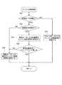
図3は、ハイブリッドコントロールモジュール81にて実行されるエンジン始動制御処理流れを示す(エンジン始動制御手段)。以下、エンジン始動制御処理構成をあらわす図3の各ステップについて説明する。このフローチャートは、エンジン始動要求の出力により開始し、横置きエンジン2のエンジン始動完了判定により終了する。 FIG. 3 shows a flow of engine start control processing executed by the hybrid control module 81 (engine start control means). Hereinafter, each step of FIG. 3 representing the engine start control processing configuration will be described. This flowchart starts when an engine start request is output, and ends when the
ステップS01では、強電モータ始動(=MG始動)であるか否かを判断する。YES(強電モータ始動)の場合はステップS02へ進み、NO(スタータモータ始動)の場合はステップS03へ進む。
ここで、強電モータ始動の判断は、スタータモータ始動条件以外であるとき、強電モータ始動であると判断する。スタータモータ始動条件は、
・低温時(エンジン水温、強電バッテリ温度、T/M油温が所定値以下)
・高温時(モータ温度、強電バッテリが所定値以上)
の条件の何れかが成立したときスタータモータ始動とする。In step S01, it is determined whether or not a strong electric motor start (= MG start) is performed. If YES (high electric motor start), the process proceeds to step S02. If NO (starter motor start), the process proceeds to step S03.
Here, when the determination on the start of the high electric motor is outside the starter motor start condition, it is determined that the high electric motor is started. Starter motor start condition is
・ Low temperature (engine water temperature, high-power battery temperature, T / M oil temperature is below specified value)
・ High temperature (motor temperature, high-power battery is above the specified value)
The starter motor is started when any of the above conditions is satisfied.
ステップS02では、ステップS01での強電モータ始動であるとの判断に続き、音振優先始動であるか否かを判断する。YES(音振優先始動)の場合はステップS05へ進み、NO(通常始動)の場合はステップS04へ進む。
ここで、音振優先始動であるとの判断は、上記音振優先始動条件(a),(b)のいずれかが成立することにより行う。In step S02, it is determined whether or not the sound vibration priority start is performed following the determination that the strong electric motor is started in step S01. If YES (sound vibration priority start), the process proceeds to step S05. If NO (normal start), the process proceeds to step S04.
Here, the determination that the sound vibration priority start is performed is made when either of the sound vibration priority start conditions (a) and (b) is satisfied.
ステップS03では、ステップS01でのスタータモータ始動であるとの判断に続き、スタータモータ1によるエンジン始動制御(「スタータ始動モード」による制御)を実施し、リターンへ進む。 In step S03, following the determination that the starter motor is started in step S01, engine start control by the starter motor 1 (control in "starter start mode") is performed, and the process proceeds to return.
ステップS04では、ステップS02での通常始動であるとの判断、ステップS06でのチェンジマインド有りの判断に続き、モータ/ジェネレータ4(強電モータ)による通常のエンジン始動制御(「通常始動モード」による制御)を実施し、リターンへ進む。 In step S04, following the determination of normal start in step S02 and the determination of the presence of change mind in step S06, normal engine start control by the motor / generator 4 (high electric motor) (control in “normal start mode”) ) And proceed to return.
ステップS05では、ステップS02での音振優先始動であるとの判断に続き、モータ/ジェネレータ4(強電モータ)による音振優先エンジン始動制御(「音振優先始動モード」による制御)を実施し、ステップS06へ進む。 In step S05, following the determination that the sound vibration priority start is performed in step S02, the sound vibration priority engine start control by the motor / generator 4 (high electric motor) (control in the “sound vibration priority start mode”) is performed. The process proceeds to step S06.
ステップS06では、ステップS05での音振優先エンジン始動制御の実施に続き、通常始動条件へチェンジマインド無しか否かを判断する。YES(チェンジマインド無し)の場合はリターンへ進み、NO(チェンジマインド有り)の場合はステップS04へ進む。
ここで、「チェンジマインド無し」は、音振優先エンジン始動制御中、上記音振優先始動条件(a),(b)の何れかが成立したままであることにより判断される。「チェンジマインド有り」は、音振優先エンジン始動制御中、上記音振優先始動条件(a),(b)の何れかが非成立になることにより判断される。In step S06, following the implementation of the sound vibration priority engine start control in step S05, it is determined whether or not there is no change mind to the normal start condition. If YES (no change mind), the process proceeds to return, and if NO (change mind exists), the process proceeds to step S04.
Here, “no change mind” is determined by the fact that either of the sound vibration priority start conditions (a) and (b) is still satisfied during the sound vibration priority engine start control. “There is a change mind” is determined when either of the sound vibration priority start conditions (a) and (b) is not satisfied during the sound vibration priority engine start control.
次に、作用を説明する。
実施例1のFFハイブリッド車両の制御装置における作用を、[エンジン始動制御作用]、[音振優先始動モードによるエンジン始動制御作用]に分けて説明する。Next, the operation will be described.
The operation of the control apparatus for the FF hybrid vehicle of the first embodiment will be described separately for [engine start control operation] and [engine start control operation in sound vibration priority start mode].
[エンジン始動制御作用]
エンジン始動要求があったときのエンジン始動制御作用を、図3に示すフローチャートに基づき説明する。[Engine start control action]
The engine start control operation when there is an engine start request will be described based on the flowchart shown in FIG.
まず、エンジン始動要求があったとき、スタータモータ始動条件が成立していると、図3のフローチャートにおいて、ステップS01→ステップS03→リターンへと進む流れが繰り返される。ステップS03では、スタータモータ1を用いた「スタータ始動モード」によるエンジン始動制御が実施される。 First, when there is an engine start request, if the starter motor start condition is satisfied, the flow from step S01 to step S03 to return is repeated in the flowchart of FIG. In step S03, engine start control by the “starter start mode” using the
次に、エンジン始動要求があったとき、スタータモータ始動条件が非成立、かつ、音振優先始動条件が非成立であると、図3のフローチャートにおいて、ステップS01→ステップS02→ステップS04→リターンへと進む流れが繰り返される。ステップS04では、モータ/ジェネレータ4(強電モータ)を用いた「通常始動モード」によるエンジン始動制御が実施される。 Next, when there is an engine start request, if the starter motor start condition is not satisfied and the sound vibration priority start condition is not satisfied, in the flowchart of FIG. 3, go to step S01 → step S02 → step S04 → return. The flow going forward is repeated. In step S04, engine start control in the “normal start mode” using the motor / generator 4 (high electric motor) is performed.
一方、エンジン始動要求があったとき、スタータモータ始動条件は非成立であるが、音振優先始動条件が成立であると、図3のフローチャートにおいて、ステップS01→ステップS02→ステップS05へと進む。ステップS05では、モータ/ジェネレータ4(強電モータ)を用いた「音振優先始動モード」によるエンジン始動制御が実施される。そして、「音振優先始動モード」によるエンジン始動制御中、ステップS05からステップS06へと進み、ステップS06では、通常始動条件へチェンジマインド無しか否かが判断される。ステップS06にて「チェンジマインド無し」と判断された場合は、音振優先エンジン始動制御がそのまま続行される。しかし、ステップS06にて「チェンジマインド有り」と判断された場合は、ステップS06からステップS04へと進み、「音振優先始動モード」によるエンジン始動制御から、「通常始動モード」によるエンジン始動制御へと切り替えられる。 On the other hand, when there is an engine start request, the starter motor start condition is not satisfied, but if the sound vibration priority start condition is satisfied, the process proceeds from step S01 to step S02 to step S05 in the flowchart of FIG. In step S05, engine start control is performed in the “sound vibration priority start mode” using the motor / generator 4 (high electric motor). Then, during engine start control in the “sound vibration priority start mode”, the process proceeds from step S05 to step S06. In step S06, it is determined whether or not there is no change mind to the normal start condition. If it is determined in step S06 that “no change mind”, the sound vibration priority engine start control is continued as it is. However, if it is determined in step S06 that “change mind exists”, the process proceeds from step S06 to step S04, and the engine start control in “sound vibration priority start mode” is changed to the engine start control in “normal start mode”. Can be switched.
上記のように、実施例1では、エンジン始動要求時、駆動レンジの選択条件と駆動力要求が小さいという条件が成立すると、音振低減性能を優先する音振優先始動モードを選択して横置きエンジン2を始動する構成を採用した。
すなわち、エンジン始動モードとして、駆動力応答性能を優先する「通常始動モード」と、音振低減性能を優先する「音振優先始動モード」と、を有する場合、通常、停車レンジ(P,Nレンジ)の選択時に「音振優先始動モード」が選択される。
これに対し、駆動レンジ(D,Rレンジなど)の選択時であっても、ブレーキ踏み込による停車中などのように、暗騒音が小さくてエンジン始動による振動や騒音に対し乗員が敏感となる状況がある。この点に着目し、エンジン始動要求時、レンジ位置選択条件を駆動レンジ選択条件まで拡大適用し、駆動レンジの選択条件と駆動力要求が小さいという条件が成立すると、「音振優先始動モード」を選択するようにした。
この結果、駆動レンジの選択時、駆動力要求が小さい場合に騒音や振動の発生を抑えた静かなエンジン始動を達成することができる。As described above, in the first embodiment, when the engine start request is satisfied and the condition that the drive range selection condition and the drive force request are small is satisfied, the sound vibration priority start mode that prioritizes the sound vibration reduction performance is selected and placed horizontally. A configuration for starting the
That is, when the engine start mode includes a “normal start mode” that prioritizes driving force response performance and a “sound vibration priority start mode” that prioritizes sound vibration reduction performance, the stop range (P, N range) is usually used. “Sound vibration priority start mode” is selected.
On the other hand, even when the drive range (D, R range, etc.) is selected, the background noise is small, such as when the vehicle is stopped by depressing the brake, and the occupant is sensitive to vibration and noise caused by engine start. There is a situation. Focusing on this point, when the engine start request is applied, the range position selection condition is expanded to the drive range selection condition, and if the condition that the drive range selection condition and the drive force requirement are small is satisfied, the “sound vibration priority start mode” is set. It was made to choose.
As a result, when the driving range is selected, it is possible to achieve a quiet engine start with reduced noise and vibration when the driving force requirement is small.
実施例1では、「音振優先始動モード」によりエンジン始動制御を実施している際に、「音振優先始動モード」の選択条件が非成立になった場合、「通常始動モード」に切り替える構成を採用した。
すなわち、「音振優先始動モード」の場合は、燃料噴射タイミングを遅らせているので、すぐに駆動力を発生できない。そのため、Dレンジでブレーキを踏んで停車した直後に発進を意図してブレーキ足離し操作及びアクセル踏み込み操作が行われた場合、「音振優先始動モード」を維持していると、車両を発進させる駆動力の発生が遅れてしまい発進性能を低下させることになる。
これに対し、ブレーキ足離し操作や車速の発生により「音振優先始動モード」の選択条件が非成立になった場合は、「通常始動モード」に切り替えるようにしている。
したがって、ブレーキ停車直後に始動発進を意図した場合、横置きエンジン2の燃料噴射タイミングが早められ、発進に必要な駆動力を応答遅れなく発生させることで、発進性能を確保することができる。In the first embodiment, when engine start control is performed in the “sound vibration priority start mode”, when the selection condition of the “sound vibration priority start mode” is not satisfied, the configuration is switched to the “normal start mode”. It was adopted.
That is, in the “sound vibration priority start mode”, since the fuel injection timing is delayed, the driving force cannot be generated immediately. Therefore, when the brake release operation and the accelerator depression operation are performed with the intention of starting immediately after stepping on the brake in the D range, the vehicle is started if the "sound vibration priority start mode" is maintained. The generation of the driving force is delayed and the starting performance is lowered.
On the other hand, when the selection condition of the “sound vibration priority start mode” is not satisfied due to the brake foot release operation or the generation of the vehicle speed, the mode is switched to the “normal start mode”.
Therefore, when starting and starting is intended immediately after stopping the brake, the fuel injection timing of the horizontally mounted
実施例1では、「音振優先始動モード」の選択条件を、駆動レンジの選択条件と、ブレーキ操作による停車中条件とする構成を採用した。
したがって、信号待ちで、駆動レンジ(Dレンジ)でブレーキを踏んでの停車中に横置きエンジン2を停車始動するとき、音振性能を優先して、静かに横置きエンジン2を始動することができる。In the first embodiment, a configuration is adopted in which the selection condition of the “sound vibration priority start mode” is the driving range selection condition and the stopping condition by the brake operation.
Therefore, when the
[音振優先始動モードによるエンジン始動制御作用]
「音振優先始動モード」によるエンジン始動制御作用を、図4〜図6に示すタイムチャートに基づき説明する。[Engine start control by sound vibration priority start mode]
The engine start control action by the “sound vibration priority start mode” will be described based on the time charts shown in FIGS.
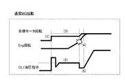
「通常始動モード」によるエンジン始動制御は、図4に示すタイムチャートにしたがって行われる。すなわち、
(1)強電バッテリ出力を拡大しない(N秒定格値)。
(2)クランキングトルクをMtとする。
(3)クランキングモータ回転数をMnとする。
(4)燃料噴射タイミングは、エンジン回転数が燃料噴射回転数になると即噴射。
(5)第1クラッチCL1の油圧を、燃料噴射タイミングに合わせて一時的に下げる。
とする。The engine start control in the “normal start mode” is performed according to the time chart shown in FIG. That is,
(1) Do not increase the high-power battery output (N-second rated value).
(2) The cranking torque is Mt.
(3) Set the cranking motor speed to Mn.
(4) The fuel injection timing is instant when the engine speed reaches the fuel injection speed.
(5) The hydraulic pressure of the first clutch CL1 is temporarily lowered in accordance with the fuel injection timing.
And
したがって、(3)の即噴射により燃料噴射タイミングが早期になると共に、(4)のCL1油圧低下によりモータトルクを駆動力に回すことができるというように、駆動力応答性能を優先したエンジン始動制御となる。 Therefore, the engine start control gives priority to the driving force response performance so that the fuel injection timing is advanced by the immediate injection of (3) and the motor torque can be turned to the driving force by the decrease of the CL1 oil pressure of (4). It becomes.
しかし、クランキングトルクやクランキングモータ回転数が低いことで、図6の矢印Aに示すように、エンジン始動制御中にエンジン回転数が低下する。このため、エンジン回転数が、エンジンマウントの共振帯や車体共振帯に停滞し、図6の矢印Bに示すように、エンジンクランキング領域にてフロア振動が発生する。また、エンジン負圧の発達を待つことなく、エンジン回転数が燃料噴射回転数になると即噴射することで、図6の矢印Cに示すように、初爆トルクによるフロア振動が発生する。 However, since the cranking torque and the cranking motor rotation speed are low, the engine rotation speed is reduced during the engine start control as indicated by an arrow A in FIG. For this reason, the engine rotational speed stagnates in the resonance band of the engine mount or the vehicle body resonance band, and floor vibration occurs in the engine cranking region as shown by an arrow B in FIG. Further, as soon as the engine speed reaches the fuel injection speed without waiting for the development of the engine negative pressure, the floor vibration is generated by the initial explosion torque as shown by the arrow C in FIG.
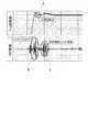
これに対し、「音振優先始動モード」によるエンジン始動制御は、図5に示すタイムチャートにしたがって行われる。すなわち、
(1’)強電バッテリ出力を拡大する(n秒(<N秒)定格値)。
(2’)クランキングトルクをMtより大きなトルクとする。
(3’)クランキングモータ回転数をMnより高い回転数とする。但し、クランキングトルクの上昇を優先する。
(4’)燃料噴射タイミングは、エンジン負圧が発達するまでクランキング回転を行った後。
(5’)第1クラッチCL1の油圧を下げない。
とする。On the other hand, engine start control in the “sound vibration priority start mode” is performed according to the time chart shown in FIG. That is,
(1 ') Expand the high-power battery output (n seconds (<N seconds) rated value).
(2 ') The cranking torque is larger than Mt.
(3 ') The cranking motor speed is set higher than Mn. However, priority is given to an increase in cranking torque.
(4 ') Fuel injection timing is after cranking rotation until engine negative pressure develops.
(5 ') The hydraulic pressure of the first clutch CL1 is not lowered.
And
したがって、(2’)のクランキングトルク上昇により、200rpm〜400rpmのエンジンマウント共振帯を素早く通過する。(3’)のクランキングモータ回転数を高めることで800rpm付近の車体共振帯にエンジン回転を停滞させない。これにより、エンジンクランキング領域にて図6の矢印Bに示すフロア振動が発生するのが抑えられる。 Therefore, due to the cranking torque increase of (2 '), the engine mount resonance band of 200 rpm to 400 rpm is quickly passed. By increasing the cranking motor speed of (3 '), the engine speed is not stagnated in the vehicle body resonance band near 800 rpm. This suppresses the occurrence of floor vibration indicated by arrow B in FIG. 6 in the engine cranking region.
また、(4’)の燃料噴射タイミングの遅延により、エンジン負圧が十分に発達してから燃料噴射を行うことで初爆トルクが小さくなり、初爆トルクにより図6矢印Cに示すフロア振動が発生するのが抑えられる。 Also, due to the delay of the fuel injection timing (4 '), the initial explosion torque is reduced by performing the fuel injection after the engine negative pressure has sufficiently developed, and the floor vibration indicated by arrow C in FIG. Occurrence is suppressed.
上記のように、実施例1では、「音振優先始動モード」でクランキングを行うとき、モータ/ジェネレータの電源である強電バッテリ21からの出力を一時的に拡大する。そして、「通常始動モード」でのエンジン始動制御に比べ、クランキングトルクとクランキングモータ回転数を上昇させる制御とする構成を採用した。
この制御構成により、エンジンマウント共振帯を素早く通過し、車体共振帯にエンジン回転を停滞させないエンジン始動制御になる。
したがって、「音振優先始動モード」でのエンジン始動制御時、エンジンクランキング領域にてエンジンマウント共振や車体共振によりフロア振動が発生するのを抑制することができる。As described above, in the first embodiment, when cranking is performed in the “sound vibration priority start mode”, the output from the high-
With this control configuration, engine start control is performed in which the engine mount resonance band is quickly passed and the engine rotation is not stagnated in the vehicle body resonance band.
Therefore, it is possible to suppress the occurrence of floor vibration due to engine mount resonance or vehicle body resonance in the engine cranking region during engine start control in the “sound vibration priority start mode”.
実施例1では、「音振優先始動モード」で燃料噴射するとき、クランキング回転数の上昇により即燃料噴射を開始する「通常始動モード」でのエンジン始動制御に比べ、燃料噴射開始タイミングを遅延させる制御とする構成を採用した。
この制御構成により、エンジン負圧が十分に発達してからの燃料噴射により初爆トルクが小さいエンジン始動制御になる。
したがって、「音振優先始動モード」でのエンジン始動制御時、燃料噴射領域にて初爆トルクによりフロア振動が発生するのを抑制することができる。In the first embodiment, when fuel injection is performed in the “sound vibration priority start mode”, the fuel injection start timing is delayed compared to the engine start control in the “normal start mode” in which fuel injection is started immediately by an increase in the cranking rotational speed. The configuration to be controlled is adopted.
With this control configuration, engine start control with a small initial explosion torque is performed by fuel injection after the engine negative pressure is sufficiently developed.
Therefore, at the time of engine start control in the “sound vibration priority start mode”, it is possible to suppress the occurrence of floor vibration due to the initial explosion torque in the fuel injection region.
次に、効果を説明する。
実施例1のFFハイブリッド車両の制御装置にあっては、下記に列挙する効果を得ることができる。Next, the effect will be described.
In the control apparatus for the FF hybrid vehicle according to the first embodiment, the effects listed below can be obtained.
(1) 駆動系に、エンジン(横置きエンジン2)と、クラッチ(第1クラッチ3)と、モータ(モータ/ジェネレータ4)と、駆動輪(左右前輪10L,10R)と、を備えたハイブリッド車両(FFハイブリッド車両)の制御装置において、
前記モータ(モータ/ジェネレータ4)を駆動源とするEVモードでエンジン始動要求があると、前記モータ(モータ/ジェネレータ4)をエンジンスタータとし、前記クラッチ(第1クラッチ3)の締結を開始して前記エンジン(横置きエンジン2)をクランキングするエンジン始動制御手段(ハイブリッドコントロールモジュール81)を設け、
前記エンジン始動制御手段(ハイブリッドコントロールモジュール81、図3)は、エンジン始動モードとして、駆動力応答性能を優先する通常始動モードと、音振低減性能を優先する音振優先始動モードと、を有し、エンジン始動要求時、駆動レンジの選択条件と駆動力要求が小さいという条件が成立すると、前記音振優先始動モードを選択して前記エンジン(横置きエンジン2)を始動する。
このため、駆動レンジの選択時、駆動力要求が小さい場合に騒音や振動の発生を抑えた静かなエンジン始動を達成することができる。(1) A hybrid vehicle having an engine (horizontal engine 2), a clutch (first clutch 3), a motor (motor / generator 4), and driving wheels (left and right
When there is an engine start request in an EV mode using the motor (motor / generator 4) as a drive source, the motor (motor / generator 4) is used as an engine starter and the clutch (first clutch 3) is started to be engaged. Engine start control means (hybrid control module 81) for cranking the engine (horizontal engine 2) is provided,
The engine start control means (
For this reason, when the driving range is selected, when the driving force requirement is small, it is possible to achieve a quiet engine start with suppressed generation of noise and vibration.
(2) 前記エンジン始動制御手段(ハイブリッドコントロールモジュール81、図3)は、前記音振優先始動モードによりエンジン始動制御を実施している際に、前記音振優先始動モードの選択条件が非成立になった場合、前記通常始動モードに切り替える。
このため、(1)の効果に加え、ブレーキ停車直後に始動発進を意図した場合、発進に必要な駆動力を応答遅れなく発生させることで、発進性能を確保することができる。(2) When the engine start control means (
For this reason, in addition to the effect of (1), when starting and starting is intended immediately after stopping the brake, the starting performance can be ensured by generating the driving force necessary for starting without response delay.
(3) 前記エンジン始動制御手段(ハイブリッドコントロールモジュール81、図3)は、前記音振優先始動モードの選択条件を、駆動レンジの選択条件と、ブレーキ操作による停車中条件とする。
このため、(1)又は(2)の効果に加え、信号待ちで、駆動レンジでブレーキを踏んでの停車中にエンジン(横置きエンジン2)を停車始動するとき、音振性能を優先して、静かにエンジン(横置きエンジン2)を始動することができる。(3) The engine start control means (
For this reason, in addition to the effects of (1) or (2), when the engine (horizontal engine 2) is stopped and stopped while waiting for a signal and stepping on the brake in the drive range, the sound vibration performance is given priority. The engine (horizontal engine 2) can be started quietly.
(4) 前記エンジン始動制御手段(ハイブリッドコントロールモジュール81、図3)は、前記音振優先始動モードでクランキングを行うとき、前記モータ(モータ/ジェネレータ4)の電源である強電バッテリ21からの出力を一時的に拡大し、前記通常始動モードでのエンジン始動制御に比べ、クランキングトルクとクランキングモータ回転数を上昇させる制御とする(図5)。
このため、(1)〜(3)の効果に加え、音振優先始動モードでのエンジン始動制御時、エンジンクランキング領域にてエンジンマウント共振や車体共振によりフロア振動が発生するのを抑制することができる。(4) When the engine start control means (
For this reason, in addition to the effects (1) to (3), at the time of engine start control in the sound vibration priority start mode, the occurrence of floor vibration due to engine mount resonance or vehicle body resonance in the engine cranking region is suppressed. Can do.
(5) 前記エンジン始動制御手段(ハイブリッドコントロールモジュール81、図3)は、前記音振優先始動モードで燃料噴射するとき、クランキング回転数の上昇により即燃料噴射を開始する前記通常始動モードでのエンジン始動制御に比べ、燃料噴射開始タイミングを遅延させる制御とする(図5)。
このため、(1)〜(4)の効果に加え、音振優先始動モードでのエンジン始動制御時、燃料噴射領域にて初爆トルクによりフロア振動が発生するのを抑制することができる。(5) When the engine start control means (
For this reason, in addition to the effects (1) to (4), it is possible to suppress the occurrence of floor vibration due to the initial explosion torque in the fuel injection region during engine start control in the sound vibration priority start mode.
以上、本発明のハイブリッド車両の制御装置を実施例1に基づき説明してきたが、具体的な構成については、この実施例1に限られるものではなく、請求の範囲の各請求項に係る発明の要旨を逸脱しない限り、設計の変更や追加等は許容される。 The hybrid vehicle control device of the present invention has been described based on the first embodiment. However, the specific configuration is not limited to the first embodiment, and the invention according to each claim of the claims is described. Design changes and additions are allowed without departing from the gist.
実施例1では、エンジン始動制御手段として、エンジン始動要求時、駆動レンジの選択条件と、ブレーキ操作による停車中条件が成立すると、「音振優先始動モード」を選択して横置きエンジン2を始動する例を示した。しかし、エンジン始動制御手段としては、駆動レンジの選択条件と、アクセル非操作による停車中条件が成立すると、「音振優先始動モード」を選択してエンジンを始動するものであっても良い。要するに、駆動力要求が小さいという条件を、ブレーキ操作やアクセル操作により判断するものであっても良い。 In the first embodiment, as the engine start control means, when the engine start request is satisfied, when the drive range selection condition and the stopping condition by the brake operation are satisfied, the “sound vibration priority start mode” is selected and the
実施例1では、本発明の制御装置をFFハイブリッド車両に適用する例を示した。しかし、本発明の制御装置は、FFハイブリッド車両に限らず、FRハイブリッド車両や4WDハイブリッド車両に対しても適用することができる。要するに、エンジン始動要求があると、モータをエンジンスタータとし、クラッチの締結を開始してエンジンをクランキングするエンジン始動制御を行うハイブリッド車両であれば適用できる。 In Example 1, the example which applies the control apparatus of this invention to FF hybrid vehicle was shown. However, the control device of the present invention can be applied not only to FF hybrid vehicles but also to FR hybrid vehicles and 4WD hybrid vehicles. In short, when there is an engine start request, the present invention can be applied to any hybrid vehicle that uses an engine starter as a motor and performs engine start control that starts clutch engagement and cranks the engine.
Claims (3)
Translated fromJapanese前記モータを駆動源とするEVモードでエンジン始動要求があると、前記モータをエンジンスタータとし、前記クラッチの締結を開始して前記エンジンをクランキングするエンジン始動制御手段を設け、
前記エンジン始動制御手段は、エンジン始動モードとして、駆動力応答性能を優先する通常始動モードと、音振低減性能を優先する音振優先始動モードと、を有し、エンジン始動要求時、駆動レンジの選択条件と、ブレーキ操作による停車中条件が成立すると、前記音振優先始動モードを選択して前記エンジンを始動し、
前記駆動レンジでのブレーキ停車中にエンジン始動要求があり、前記音振優先始動モードによりエンジン始動制御を実施している際に、発進を意図してブレーキ足離し操作が行われたことで前記音振優先始動モードの選択条件が非成立になった場合、クランキング回転数の上昇により即燃料噴射を開始する前記通常始動モードに切り替える
ことを特徴とするハイブリッド車両の制御装置。In a hybrid vehicle control device including an engine, a clutch, a motor, and drive wheels in a drive system,
When there is an engine start request in the EV mode using the motor as a drive source, an engine start control means is provided that uses the motor as an engine starter, starts fastening the clutch and cranks the engine,
The engine start control means has, as an engine start mode, a normal start mode that prioritizes driving force response performance and a sound vibration priority start mode that prioritizes sound vibration reduction performance. When the selection condition and the stopping condition by the brake operation are satisfied, the sound vibration priority start mode is selected to start the engine,
When there is an engine start request while the brake is stopped in the driving range, and the engine start control is performed in the sound vibration priority start mode, the sound is released when the brake release operation is performed with the intention of starting. A control apparatus for a hybrid vehicle, characterized in that when the selection condition for the vibration priority start mode is not satisfied, the normal start mode is switched to immediately start fuel injection by an increase in cranking rotational speed.
前記エンジン始動制御手段は、前記音振優先始動モードでクランキングを行うとき、前記モータの電源である強電バッテリからの出力を一時的に拡大し、前記通常始動モードでのエンジン始動制御に比べ、クランキングトルクとクランキングモータ回転数を上昇させる制御とする
ことを特徴とするハイブリッド車両の制御装置。In the hybrid vehicle control device according to claim 1,
When performing cranking in the sound vibration priority start mode, the engine start control means temporarily expands the output from the high-power battery that is the power source of the motor, compared to the engine start control in the normal start mode, A control device for a hybrid vehicle, characterized in that control is performed to increase cranking torque and cranking motor rotation speed.
前記エンジン始動制御手段は、前記音振優先始動モードで燃料噴射するとき、クランキング回転数の上昇により即燃料噴射を開始する前記通常始動モードでのエンジン始動制御に比べ、燃料噴射開始タイミングを遅延させる制御とする
ことを特徴とするハイブリッド車両の制御装置。In the hybrid vehicle control device according to claim 1 or 4,
The engine start control means delays the fuel injection start timing in comparison with the engine start control in the normal start mode in which fuel injection is immediately started by increasing the cranking rotation speed when fuel injection is performed in the sound vibration priority start mode. A control device for a hybrid vehicle, characterized by comprising:
Applications Claiming Priority (1)
| Application Number | Priority Date | Filing Date | Title |
|---|---|---|---|
| PCT/JP2013/077433WO2015052789A1 (en) | 2013-10-09 | 2013-10-09 | Control device for hybrid vehicle |
Publications (2)
| Publication Number | Publication Date |
|---|---|
| JP6070854B2true JP6070854B2 (en) | 2017-02-08 |
| JPWO2015052789A1 JPWO2015052789A1 (en) | 2017-03-09 |
Family
ID=52812637
Family Applications (1)
| Application Number | Title | Priority Date | Filing Date |
|---|---|---|---|
| JP2015541359AActiveJP6070854B2 (en) | 2013-10-09 | 2013-10-09 | Control device for hybrid vehicle |
Country Status (8)
| Country | Link |
|---|---|
| US (1) | US9586469B2 (en) |
| EP (1) | EP3056402B1 (en) |
| JP (1) | JP6070854B2 (en) |
| CN (1) | CN105636845B (en) |
| MX (1) | MX354258B (en) |
| MY (1) | MY162890A (en) |
| RU (1) | RU2619144C1 (en) |
| WO (1) | WO2015052789A1 (en) |
Families Citing this family (9)
| Publication number | Priority date | Publication date | Assignee | Title |
|---|---|---|---|---|
| JP2016210349A (en)* | 2015-05-12 | 2016-12-15 | 本田技研工業株式会社 | Vehicle sound generator |
| JP6350751B2 (en)* | 2015-06-15 | 2018-07-04 | 日産自動車株式会社 | Vehicle control method and vehicle control apparatus |
| JP6621787B2 (en)* | 2017-10-19 | 2019-12-18 | 本田技研工業株式会社 | Ignition timing control device for internal combustion engine |
| JP7014016B2 (en)* | 2018-04-02 | 2022-02-01 | トヨタ自動車株式会社 | Hybrid vehicle |
| CN111891107A (en)* | 2019-11-26 | 2020-11-06 | 长城汽车股份有限公司 | Start-stop control method and device for vehicle, vehicle and electronic equipment |
| IT202100026141A1 (en)* | 2021-10-12 | 2023-04-12 | Cnh Ind Italia Spa | METHOD AND APPARATUS FOR OPERATION OF A WORK VEHICLE |
| KR102546717B1 (en)* | 2021-12-21 | 2023-06-22 | 주식회사 현대케피코 | Method for controlling fuel injection of mild hybrid electric vehicle |
| JP7616096B2 (en)* | 2022-01-14 | 2025-01-17 | トヨタ自動車株式会社 | Hybrid vehicles |
| US11898527B2 (en)* | 2022-04-13 | 2024-02-13 | Ford Global Technologies, Llc | System and method for controlling engine starting |
Citations (4)
| Publication number | Priority date | Publication date | Assignee | Title |
|---|---|---|---|---|
| JP2000204997A (en)* | 1999-01-19 | 2000-07-25 | Mitsubishi Motors Corp | Vehicle engine starter |
| JP2008162491A (en)* | 2006-12-28 | 2008-07-17 | Toyota Motor Corp | Vehicle and control method thereof |
| JP2010137823A (en)* | 2008-12-15 | 2010-06-24 | Toyota Motor Corp | Vehicle and control method for the same |
| JP2013155605A (en)* | 2012-01-26 | 2013-08-15 | Hitachi Automotive Systems Ltd | Engine control device |
Family Cites Families (9)
| Publication number | Priority date | Publication date | Assignee | Title |
|---|---|---|---|---|
| JP3498593B2 (en)* | 1998-10-15 | 2004-02-16 | 日産自動車株式会社 | Hybrid vehicle control device |
| JP3458795B2 (en)* | 1999-10-08 | 2003-10-20 | トヨタ自動車株式会社 | Hybrid drive |
| US20050131239A1 (en)* | 2003-11-14 | 2005-06-16 | Blazecka Peter G. | Preparation of aryl-substituted butenolides using mucohalic acids |
| US7347803B2 (en)* | 2004-10-27 | 2008-03-25 | Aisin Aw Co., Ltd. | Drive apparatus for hybrid vehicle and control method and control device thereof |
| US8219303B2 (en)* | 2007-11-05 | 2012-07-10 | GM Global Technology Operations LLC | Method for operating an internal combustion engine for a hybrid powertrain system |
| JP5387487B2 (en)* | 2010-04-07 | 2014-01-15 | トヨタ自動車株式会社 | Hybrid car |
| JP5530813B2 (en)* | 2010-06-04 | 2014-06-25 | トヨタ自動車株式会社 | Hybrid vehicle and control method thereof |
| WO2012059999A1 (en)* | 2010-11-04 | 2012-05-10 | トヨタ自動車株式会社 | Control device of hybrid vehicle |
| JP2013159330A (en) | 2012-02-09 | 2013-08-19 | Toyota Motor Corp | Hybrid vehicle |
- 2013
- 2013-10-09EPEP13895392.2Apatent/EP3056402B1/enactiveActive
- 2013-10-09JPJP2015541359Apatent/JP6070854B2/enactiveActive
- 2013-10-09USUS14/917,136patent/US9586469B2/enactiveActive
- 2013-10-09CNCN201380080117.9Apatent/CN105636845B/enactiveActive
- 2013-10-09MYMYPI2016701268Apatent/MY162890A/enunknown
- 2013-10-09MXMX2016004519Apatent/MX354258B/enactiveIP Right Grant
- 2013-10-09WOPCT/JP2013/077433patent/WO2015052789A1/ennot_activeCeased
- 2013-10-09RURU2016114457Apatent/RU2619144C1/enactive
Patent Citations (4)
| Publication number | Priority date | Publication date | Assignee | Title |
|---|---|---|---|---|
| JP2000204997A (en)* | 1999-01-19 | 2000-07-25 | Mitsubishi Motors Corp | Vehicle engine starter |
| JP2008162491A (en)* | 2006-12-28 | 2008-07-17 | Toyota Motor Corp | Vehicle and control method thereof |
| JP2010137823A (en)* | 2008-12-15 | 2010-06-24 | Toyota Motor Corp | Vehicle and control method for the same |
| JP2013155605A (en)* | 2012-01-26 | 2013-08-15 | Hitachi Automotive Systems Ltd | Engine control device |
Also Published As
| Publication number | Publication date |
|---|---|
| US20160200316A1 (en) | 2016-07-14 |
| EP3056402A4 (en) | 2017-01-25 |
| MX354258B (en) | 2018-02-20 |
| JPWO2015052789A1 (en) | 2017-03-09 |
| CN105636845A (en) | 2016-06-01 |
| MY162890A (en) | 2017-07-20 |
| EP3056402B1 (en) | 2019-03-27 |
| EP3056402A1 (en) | 2016-08-17 |
| MX2016004519A (en) | 2016-07-06 |
| WO2015052789A1 (en) | 2015-04-16 |
| US9586469B2 (en) | 2017-03-07 |
| RU2619144C1 (en) | 2017-05-12 |
| CN105636845B (en) | 2017-10-24 |
Similar Documents
| Publication | Publication Date | Title |
|---|---|---|
| JP6070854B2 (en) | Control device for hybrid vehicle | |
| JP6070855B2 (en) | Control device for hybrid vehicle | |
| JP6292239B2 (en) | Control device for four-wheel drive electric vehicle | |
| JP6112214B2 (en) | Control device for hybrid vehicle | |
| JP5973710B2 (en) | Control device for hybrid vehicle | |
| JP6187059B2 (en) | Control device for hybrid vehicle | |
| JP6065987B2 (en) | Control device for hybrid vehicle | |
| JP6369210B2 (en) | Control device for hybrid vehicle | |
| JP6229399B2 (en) | Control device for hybrid vehicle | |
| JP6286972B2 (en) | Control device for hybrid vehicle | |
| JP6433695B2 (en) | Vehicle start control device | |
| JP6287513B2 (en) | Control device for hybrid vehicle | |
| JP6369209B2 (en) | Control device for hybrid vehicle | |
| JP6512760B2 (en) | Control device for hybrid vehicle | |
| WO2015052760A1 (en) | Device for controlling hybrid vehicle | |
| JP2015203323A (en) | Power supply device for vehicle | |
| JP6229398B2 (en) | Control device for hybrid vehicle | |
| WO2015037043A1 (en) | Hybrid vehicle controller | |
| WO2015037042A1 (en) | Hybrid vehicle control device | |
| WO2016013061A1 (en) | Vehicle transmission hydraulic pressure controller |
Legal Events
| Date | Code | Title | Description |
|---|---|---|---|
| TRDD | Decision of grant or rejection written | ||
| A01 | Written decision to grant a patent or to grant a registration (utility model) | Free format text:JAPANESE INTERMEDIATE CODE: A01 Effective date:20161206 | |
| A61 | First payment of annual fees (during grant procedure) | Free format text:JAPANESE INTERMEDIATE CODE: A61 Effective date:20161219 | |
| R151 | Written notification of patent or utility model registration | Ref document number:6070854 Country of ref document:JP Free format text:JAPANESE INTERMEDIATE CODE: R151 |