JP6070044B2 - Suspension control device - Google Patents
Suspension control deviceDownload PDFInfo
- Publication number
- JP6070044B2 JP6070044B2JP2012228279AJP2012228279AJP6070044B2JP 6070044 B2JP6070044 B2JP 6070044B2JP 2012228279 AJP2012228279 AJP 2012228279AJP 2012228279 AJP2012228279 AJP 2012228279AJP 6070044 B2JP6070044 B2JP 6070044B2
- Authority
- JP
- Japan
- Prior art keywords
- component
- speed
- unit
- road surface
- stroke
- Prior art date
- Legal status (The legal status is an assumption and is not a legal conclusion. Google has not performed a legal analysis and makes no representation as to the accuracy of the status listed.)
- Active
Links
Images


Classifications
- B—PERFORMING OPERATIONS; TRANSPORTING
- B60—VEHICLES IN GENERAL
- B60G—VEHICLE SUSPENSION ARRANGEMENTS
- B60G17/00—Resilient suspensions having means for adjusting the spring or vibration-damper characteristics, for regulating the distance between a supporting surface and a sprung part of vehicle or for locking suspension during use to meet varying vehicular or surface conditions, e.g. due to speed or load
- B60G17/015—Resilient suspensions having means for adjusting the spring or vibration-damper characteristics, for regulating the distance between a supporting surface and a sprung part of vehicle or for locking suspension during use to meet varying vehicular or surface conditions, e.g. due to speed or load the regulating means comprising electric or electronic elements
- B60G17/016—Resilient suspensions having means for adjusting the spring or vibration-damper characteristics, for regulating the distance between a supporting surface and a sprung part of vehicle or for locking suspension during use to meet varying vehicular or surface conditions, e.g. due to speed or load the regulating means comprising electric or electronic elements characterised by their responsiveness, when the vehicle is travelling, to specific motion, a specific condition, or driver input
- B60G17/0165—Resilient suspensions having means for adjusting the spring or vibration-damper characteristics, for regulating the distance between a supporting surface and a sprung part of vehicle or for locking suspension during use to meet varying vehicular or surface conditions, e.g. due to speed or load the regulating means comprising electric or electronic elements characterised by their responsiveness, when the vehicle is travelling, to specific motion, a specific condition, or driver input to an external condition, e.g. rough road surface, side wind
- B—PERFORMING OPERATIONS; TRANSPORTING
- B60—VEHICLES IN GENERAL
- B60G—VEHICLE SUSPENSION ARRANGEMENTS
- B60G17/00—Resilient suspensions having means for adjusting the spring or vibration-damper characteristics, for regulating the distance between a supporting surface and a sprung part of vehicle or for locking suspension during use to meet varying vehicular or surface conditions, e.g. due to speed or load
- B60G17/015—Resilient suspensions having means for adjusting the spring or vibration-damper characteristics, for regulating the distance between a supporting surface and a sprung part of vehicle or for locking suspension during use to meet varying vehicular or surface conditions, e.g. due to speed or load the regulating means comprising electric or electronic elements
- B60G17/018—Resilient suspensions having means for adjusting the spring or vibration-damper characteristics, for regulating the distance between a supporting surface and a sprung part of vehicle or for locking suspension during use to meet varying vehicular or surface conditions, e.g. due to speed or load the regulating means comprising electric or electronic elements characterised by the use of a specific signal treatment or control method
- B—PERFORMING OPERATIONS; TRANSPORTING
- B60—VEHICLES IN GENERAL
- B60G—VEHICLE SUSPENSION ARRANGEMENTS
- B60G17/00—Resilient suspensions having means for adjusting the spring or vibration-damper characteristics, for regulating the distance between a supporting surface and a sprung part of vehicle or for locking suspension during use to meet varying vehicular or surface conditions, e.g. due to speed or load
- B60G17/06—Characteristics of dampers, e.g. mechanical dampers
- B—PERFORMING OPERATIONS; TRANSPORTING
- B60—VEHICLES IN GENERAL
- B60G—VEHICLE SUSPENSION ARRANGEMENTS
- B60G2400/00—Indexing codes relating to detected, measured or calculated conditions or factors
- B60G2400/20—Speed
- B60G2400/202—Piston speed; Relative velocity between vehicle body and wheel
- B—PERFORMING OPERATIONS; TRANSPORTING
- B60—VEHICLES IN GENERAL
- B60G—VEHICLE SUSPENSION ARRANGEMENTS
- B60G2400/00—Indexing codes relating to detected, measured or calculated conditions or factors
- B60G2400/20—Speed
- B60G2400/204—Vehicle speed
- B—PERFORMING OPERATIONS; TRANSPORTING
- B60—VEHICLES IN GENERAL
- B60G—VEHICLE SUSPENSION ARRANGEMENTS
- B60G2400/00—Indexing codes relating to detected, measured or calculated conditions or factors
- B60G2400/20—Speed
- B60G2400/206—Body oscillation speed; Body vibration frequency
- B—PERFORMING OPERATIONS; TRANSPORTING
- B60—VEHICLES IN GENERAL
- B60G—VEHICLE SUSPENSION ARRANGEMENTS
- B60G2400/00—Indexing codes relating to detected, measured or calculated conditions or factors
- B60G2400/90—Other conditions or factors
- B60G2400/91—Frequency
Landscapes
- Engineering & Computer Science (AREA)
- Mechanical Engineering (AREA)
- Vehicle Body Suspensions (AREA)
Description
Translated fromJapanese本発明は、サスペンション制御装置に関するものである。 The present invention relates to a suspension control device.
従来、この種の技術としては、例えば、特許文献1に記載の技術がある。
この特許文献1に記載の技術では、車輪速センサによって車輪速を検出し、検出した車輪速に基づいてサスペンションのストローク速度を算出する。そして、特許文献1に記載の技術では、算出したストローク速度に基づいてサスペンションのストローク状態を制御するようになっている。Conventionally, as this type of technology, for example, there is a technology described in
In the technique described in
しかしながら、特許文献1に記載の技術では、検出した車輪速に基づいてサスペンションのストローク速度を算出するため、車輪速が含んでいる外乱成分が増大すると、サスペンションのストローク速度の推定精度が低下する可能性があった。それゆえ、特許文献1に記載の技術では、サスペンションのストローク状態を制御することが困難となる可能性があった。
本発明は、上記のような点に着目し、サスペンションのストローク速度の推定精度を向上可能とすることを課題としている。However, in the technique described in
The present invention pays attention to the above points, and makes it a subject to improve the estimation accuracy of the stroke speed of the suspension.
上記課題を解決するため、本発明の一態様では、基準車体速成分に基づいて設定周波数帯域を設定する。続いて、本発明の一態様では、サスペンションのストローク速度から設定周波数帯域の成分を除去する。続いて、本発明の一態様では、設定周波数帯域の成分を除去した後のストローク速度に基づいて、サスペンションのストローク状態を制御する。 In order to solve the above problems, in one aspect of the present invention, a set frequency band is set based on a reference vehicle body speed component. Subsequently, in one aspect of the present invention, a component in the set frequency band is removed from the stroke speed of the suspension. Subsequently, in one aspect of the present invention, the stroke state of the suspension is controlled based on the stroke speed after removing the component of the set frequency band.
本発明の一態様によれば、サスペンションのストローク速度から設定周波数帯域に存在する外乱成分を除去できる。これにより、本発明の一態様によれば、サスペンションのストローク速度の推定精度を向上できる。 According to the aspect of the present invention, it is possible to remove disturbance components existing in the set frequency band from the stroke speed of the suspension. Thereby, according to one aspect of the present invention, the estimation accuracy of the stroke speed of the suspension can be improved.
次に、本発明に係る実施形態について図面を参照して説明する。
(構成)
車両Aの構成について図1を参照して説明する。
本実施形態の車両Aは、前輪および後輪のそれぞれを個別に操舵可能な4輪操舵車両とする。操舵とは、車輪の向きを変えて進む方向を変更すること(転舵)をいう。
図1は、本実施形態の車両Aの構成を表す概念図である。
図1に示すように、車両Aは、加速度センサ1、車輪速センサ2、前輪操舵角センサ3、後輪操舵角センサ4、マスタ圧センサ5、エンジントルクセンサ6、エンジン回転数センサ7、AT入力軸センサ8、AT出力軸センサ9、および車体速センサ10を備える。また、車両Aは、車体横速センサ11、およびヨーレイトセンサ12を備える。Next, an embodiment according to the present invention will be described with reference to the drawings.
(Constitution)
The configuration of the vehicle A will be described with reference to FIG.
The vehicle A of the present embodiment is a four-wheel steering vehicle that can individually steer front wheels and rear wheels. Steering refers to changing the direction of the wheels by changing the direction of the wheels (steering).
FIG. 1 is a conceptual diagram illustrating a configuration of a vehicle A according to the present embodiment.
As shown in FIG. 1, the vehicle A includes an
加速度センサ1は、バネ上の平面視で互いに異なる3箇所以上の位置それぞれに配設され、バネ上上下加速度Gs1、Gs2、Gs3を検出する。バネ上上下加速度Gs1、Gs2、Gs3とは、加速度センサ1を配設した位置におけるバネ上の上下方向の加速度である。そして、加速度センサ1は、検出結果を表す検出信号を制御装置20に出力する。 The
車輪速センサ2は、車輪14のアクスルそれぞれに配設されている。車輪速センサ2は、車輪速ωsFL、ωsFR、ωsRL、ωsRRを検出する。車輪速ωsFL、ωsFR、ωsRL、ωsRRとは、車輪14それぞれの単位時間当たりの回転角である。車輪速センサ2としては、例えば、アクスルの加速度を検出する加速度センサ、および加速度センサの検出結果を積分し積分結果を車輪速ωsFL、ωsFR、ωsRL、ωsRRとするディジタルフィルタを含むものを採用できる。そして、車輪速センサ2は、検出結果を表す検出信号を制御装置20に出力する。 The
前輪操舵角センサ3は、前輪14の操舵角δfを検出する。そして、前輪操舵角センサ3は、検出結果を表す検出信号を制御装置20に出力する。
後輪操舵角センサ4は、後輪14の操舵角δrを検出する。そして、後輪操舵角センサ4は、検出結果を表す検出信号を制御装置20に出力する。
マスタ圧センサ5は、マスタシリンダ圧Pを検出する。そして、マスタ圧センサ5は、検出結果を表す検出信号を制御装置20に出力する。The front wheel
The rear wheel steering angle sensor 4 detects the steering angle δr of the
The
エンジントルクセンサ6は、エンジントルクTeを検出する。そして、エンジントルクセンサ6は、検出結果を表す検出信号を制御装置20に出力する。
エンジン回転数センサ7は、エンジン回転数TACHOを検出する。そして、エンジン回転数センサ7は、検出結果を表す検出信号を制御装置20に出力する。
AT入力軸センサ8は、AT入力軸回転数INREVを検出する。AT入力軸回転数INREVとは、自動変速機の入力軸の単位時間当たりの回転数である。そして、AT入力軸センサ8は、検出結果を表す検出信号を制御装置20に出力する。The engine torque sensor 6 detects the engine torque Te. Then, the engine torque sensor 6 outputs a detection signal representing the detection result to the
The engine speed sensor 7 detects the engine speed TACHO. Then, the engine speed sensor 7 outputs a detection signal representing the detection result to the
The AT
AT出力軸センサ9は、AT出力軸回転数OUTREVを検出する。AT出力軸回転数OUTREVとは、自動変速機の出力軸の単位時間当たりの回転数である。そして、AT出力軸センサ9は、検出結果を表す検出信号を制御装置20に出力する。
車体速センサ10は、車体速Vを検出する。そして、車体速センサ10は、検出結果を表す検出信号を制御装置20に出力する。The AT output shaft sensor 9 detects the AT output shaft rotational speed OUTREV. The AT output shaft rotational speed OUTREV is the rotational speed per unit time of the output shaft of the automatic transmission. Then, the AT output shaft sensor 9 outputs a detection signal representing the detection result to the
The vehicle
車体横速センサ11は、車体横速Vxを検出する。そして、車体横速センサ11は、検出結果を表す検出信号を制御装置20に出力する。
ヨーレイトセンサ12は、ヨーレイトγを検出する。そして、ヨーレイトセンサ12は、検出結果を表す検出信号を制御装置20に出力する。
なお、本実施形態では、バネ上上下加速度Gs1、Gs2、Gs3等、サスペンション制御装置で用いる各種物理量をセンサ1〜12で検出する例を示したが、他の構成を採用することもできる。例えば、各種物理量をオブザーバ等で推定する構成としてもよい。The vehicle body lateral speed sensor 11 detects the vehicle body lateral speed Vx. The vehicle body lateral speed sensor 11 outputs a detection signal representing the detection result to the
The
In this embodiment, the example in which various physical quantities used in the suspension control device such as the sprung vertical acceleration Gs1, Gs2, and Gs3 are detected by the
車両Aは、ショックアブソーバ13を備える。
ショックアブソーバ13は、バネ上と車輪14との間それぞれに介装されている。
ショックアブソーバ13は、アクチュエータ15を備える。アクチュエータ15は、制御装置20からの指令に従って、オリフィスの大きさを変更する。これにより、ショックアブソーバ13は、オリフィスの大きさを小さくすることで減衰力を増大できる。一方、オリフィスの大きさを大きくすることで減衰力を低減できる。制御装置20が出力する指令としては、アクチュエータ指令信号、または指令電流を採用できる。The vehicle A includes a
The
The
車両Aは、制御装置20を備える。
制御装置20は、マイクロプロセッサからなる。マイクロプロセッサは、A/D変換回路、D/A変換回路、中央演算処理装置およびメモリ等から構成した集積回路を備える。制御装置20は、メモリが格納するプログラムに従って、各種センサ1〜12が出力する検出信号、つまり、ドライバ操作量、車両Aの状態に基づき、ショックアブソーバ13の減衰力を算出する。ドライバ操作量とは、操舵角δf、δr、マスタシリンダ圧Pである。また、車両Aの状態量とは、エンジントルクTe、エンジン回転数TACHO、AT入力軸回転数INREV、AT出力軸回転数OUTREVである。そして、制御装置20は、算出した減衰力を実現可能なオリフィス径に変更する指令をアクチュエータ15に出力する。これにより、ストローク速度やストローク量等、サスペンションのストローク状態を制御する。The vehicle A includes a
The
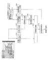
図2は、マイクロプロセッサが実行するプログラムの構成を表すブロック図である。
図2に示すように、制御装置20は、マイクロプロセッサが実行するプログラムにより、図2の制御ブロックを構成する。この制御ブロックは、目標値演算部21、状態推定部22、姿勢偏差演算部23、バネ上姿勢制御力演算部24、目標制御力マネジメント部25、および制御信号変換部26を備える。FIG. 2 is a block diagram showing a configuration of a program executed by the microprocessor.
As shown in FIG. 2, the
目標値演算部21は、各種センサ1〜10が出力する検出信号に基づいて、車両Aの目標姿勢および目標ドライバ制御力Pdを算出する(図3ステップS101、S102)。目標ドライバ制御力Pdとは、目標姿勢を実現するためのショックアブソーバ13の減衰力(フィードフォワード値)である。そして、目標値演算部21は、算出した目標姿勢を姿勢偏差演算部23に出力し、目標ドライバ制御力Pdを目標制御力マネジメント部25に出力する。 The target
状態推定部22は、加速度センサ1および車輪速センサ2が出力する検出信号に基づいて、バネ上の状態量を算出する(図3ステップS103)。バネ上の状態量とは、バネ上の上下速度、ロール速度、ピッチ速度、およびバウンス速度である。また、状態推定部22は、車輪速センサ2が出力する検出信号に基づいて、サスペンションのストローク速度であるストローク速度推定値VzSHを算出する(図3ステップS104)。ストローク速度推定値VzSHの算出方法としては、例えば、加速度センサ1の検出値に基づきディジタルフィルタを用いて疑似積分を行うことで、速度次元の物理量を推定する方法を採用できる。また、車輪速センサ2が検出した車輪速ωsFL、ωsFR、ωsRL、ωsRR等からバネ上およびバネ下の状態を検出することで、速度次元の物理量を推定する方法も採用できる。そして、状態推定部22は、算出したバネ上の状態を車両Aの実姿勢として姿勢偏差演算部23に出力し、ストローク速度推定値VzSHを制御信号変換部26に出力する。 The
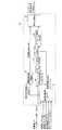
図4は、状態推定部22の構成を表すブロック図である。
図4に示すように、状態推定部22は、基準車輪速演算部27、加減算器28、ジオメトリ変化上下成分変換部29、ストローク速度校正部30、振動周波数演算部31、および信号処理部32を備える。FIG. 4 is a block diagram illustrating the configuration of the
As shown in FIG. 4, the
基準車輪速演算部27は、各種センサ2、3、4、11、12が出力する検出信号に基づいて、車輪速ωs(=[ωsFL、ωsFR、ωsRL、ωsRR]T)、操舵角δf、δr、車体横速Vx、およびヨーレイトγ等の物理量を読み込む。続いて、基準車輪速演算部27は、読み込んだ物理量に基づいて、基準車輪速成分ω0(=[ω0FL、ω0FR、ω0RL、ω0RR]T)を算出する。基準車輪速成分ω0とは、車輪速ωsから車両平面運動成分および路面外乱成分を除去した車輪速である。車両平面運動成分とは、車輪速ωsが含む成分のうち、車両Aの平面運動に起因する成分である。例えば、操舵角δf、δrおよびヨーレイトγに起因する成分である。路面外乱成分とは、車輪速ωsが含む成分のうち、路面の凹凸等、路面状態によって発生した車両Aのロール運動、およびピッチ運動に起因する外乱成分である。そして、基準車輪速演算部27は、算出結果を加減算器28に出力する。Based on the detection signals output from the
また、基準車輪速演算部27は、読み込んだ物理量に基づいて、基準車体速成分Vb0(=[Vb0FL、Vb0FR、Vb0RL、Vb0RR]T)を算出する。基準車体速成分Vb0とは、車輪速ωsから車両平面運動成分および路面外乱成分を除去して得た車体速である。そして、基準車輪速演算部27は、算出結果を振動周波数演算部31に出力する。The reference wheel
図5は、基準車輪速演算部27の構成を表すブロック図である。
具体的には、図5に示すように、基準車輪速演算部27は、平面運動成分抽出部33、路面外乱除去部34、および基準車体速再配分部35を備える。
平面運動成分抽出部33は、車輪速センサ2が出力する検出信号が表す車輪速ωsに基づいて、車輪14の単位時間当たりの移動距離を表す車輪速Vs(=[VFL、VFR、VRL、VRR]T)を算出する。続いて、平面運動成分抽出部33は、各種センサ3、4、11、12が出力する検出信号に基づいて、操舵角δf、δr、車体横速Vx、ヨーレイトγ等の物理量を読み込む。ここで、操舵角δf、δr、車体横速Vxは運転者の操作状態である。また、車体横速Vx、ヨーレイトγは車両Aの状態量である。続いて、平面運動成分抽出部33は、算出した車輪速Vs、および読み込んだ物理量(運転者の操作状態、車両Aの状態量)に基づき、下記(1)式に従って平面運動除去後成分V0を算出する。平面運動除去後成分V0とは、車両平面運動成分を除去した車体速の成分である。そして、平面運動成分抽出部33は、算出した平面運動除去後成分V0を路面外乱除去部34に出力する。FIG. 5 is a block diagram showing the configuration of the reference wheel
Specifically, as shown in FIG. 5, the reference wheel
The plane motion
V0FL={VFL―(Vx+Lf・γ)sinδf}/cosδf+Tf/2・γ
V0FR={VFR―(Vx+Lf・γ)sinδf}/cosδf―Tf/2・γ
V0RL={VRL―(Vx―Lr・γ)sinδf}/cosδf―Tr/2・γ
V0RR={VRR―(Vx―Lr・γ)sinδf}/cosδf―Tr/2・γ ・・・(1)V0FL = {VFL− (Vx + Lf · γ) sinδf} / cosδf + Tf / 2 · γ
V0FR = {VFR− (Vx + Lf · γ) sinδf} / cosδf−Tf / 2 · γ
V0RL = {VRL− (Vx−Lr · γ) sinδf} / cosδf−Tr / 2 · γ
V0RR = {VRR− (Vx−Lr · γ) sinδf} / cosδf−Tr / 2 · γ (1)
但し、図6に示すように、Lfは車両重心点と前車軸との間の距離、Lrは車両重心点と後車軸との間の距離、Tfは前輪側のトレッド、Trは後輪側のトレッドである。
なお、上記(1)式は車両Aの平面運動モデルを表す下記(2)式の逆モデルである。
VFL=(V―Tf/2・γ)cosδf+(Vx+Lf・γ)sinδf
VFR=(V+Tf/2・γ)cosδf+(Vx+Lf・γ)sinδf
VRL=(V―Tr/2・γ)cosδr+(Vx―Lr・γ)sinδr
VRR=(V―Tr/2・γ)cosδr+(Vx―Lr・γ)sinδr ・・・(2)However, as shown in FIG. 6, Lf is the distance between the center of gravity of the vehicle and the front axle, Lr is the distance between the center of gravity of the vehicle and the rear axle, Tf is the tread on the front wheel side, and Tr is the tread on the rear wheel side. It is a tread.
The above equation (1) is an inverse model of the following equation (2) representing a plane motion model of the vehicle A.
VFL = (V−Tf / 2 · γ) cosδf + (Vx + Lf · γ) sinδf
VFR = (V + Tf / 2 · γ) cosδf + (Vx + Lf · γ) sinδf
VRL = (V−Tr / 2 · γ) cosδr + (Vx−Lr · γ) sinδr
VRR = (V−Tr / 2 · γ) cosδr + (Vx−Lr · γ) sinδr (2)
例えば、車輪14の操舵角δf、δrが0であると、車体速Vの大きさおよび方向は車輪速Vsとの大きさおよび方向と一致する。ここで、運転者が操舵操作を行い、車輪14に操舵角δf、δrが発生すると、車体速Vに対し車輪速Vsの大きさおよび方向が変動する。それゆえ、車両Aの平面運動モデルの逆モデルを用いて平面運動除去後成分V0を算出することで、この変動を除去でき、平面運動成分、つまり、操舵角δf、δrおよびヨーレイトγに起因する成分を除去した車体速の成分を抽出できる。
これにより、車両平面運動成分および外乱成分が混入した車輪速ωsから、車両平面運動成分を除去した車体速の成分である平面運動除去後成分V0を抽出できる。For example, when the steering angles δf and δr of the
Thereby, the post-planar motion removal component V0, which is the vehicle speed component from which the vehicle plane motion component is removed, can be extracted from the wheel speed ωs in which the vehicle plane motion component and the disturbance component are mixed.
図7は、路面外乱除去部34の構成を表すブロック図である。
図7に示すように、路面外乱除去部34は、平面運動成分抽出部33が出力する平面運動除去後成分V0に基づき、下記(3)式に従って前輪側平均車体速VbFav、後輪側平均車体速VbRavを算出する。前輪側平均車体速VbFavとは、左右の前輪14(2輪)の平面運動除去後成分V0FL、V0FRの平均値である。後輪側平均車体速VbRavとは、左右の後輪14(2輪)の平面運動除去後成分V0RL、V0RRの平均値である。
VbFav=1/2・(V0RL+V0RR)
VbRav=1/2・(V0FL+V0FR) ・・・(3)FIG. 7 is a block diagram illustrating a configuration of the road surface
As shown in FIG. 7, the road
VbFav = 1/2 ・ (V0RL + V0RR)
VbRav = 1/2 ・ (V0FL + V0FR) (3)
例えば、車両Aにロール運動が発生すると、平面運動除去後成分V0FL、V0FRに互いに反対方向で且つほぼ同程度の大きさの変動が発生する。それゆえ、左右の前輪14の平面運動除去後成分V0FL、V0FRの平均値を算出することで、この変動を除去でき、車両Aのロール運動に起因する外乱成分を除去した車体速の成分を抽出できる。同様に、平面運動除去後成分V0RL、V0RRについても当該成分を抽出できる。 For example, when a roll motion occurs in the vehicle A, fluctuations in the opposite directions and substantially the same magnitude occur in the post-planar motion removal components V0FL and V0FR. Therefore, by calculating the average value of the components V0FL and V0FR after removing the plane motion of the left and right
また、路面外乱除去部34は、算出した前輪側平均車体速VbFav、後輪側平均車体速VbRavに基づき、下記(4)式に従って基準車体速成分Vb0を算出する。基準車体速成分Vb0は、前輪側平均車体速VbFav、後輪側平均車体速VbRavから、車両Aのピッチ運動およびバウンス運動に起因する外乱成分を除去した車体速である。そして、路面外乱除去部34は、算出した基準車体速成分Vb0を基準車体速再配分部35に出力する。
Vb0FL=VbRav
Vb0FR=VbRav
Vb0RL=VbFav
Vb0RR=VbFav ・・・(4)Further, the road surface
Vb0FL = VbRav
Vb0FR = VbRav
Vb0RL = VbFav
Vb0RR = VbFav (4)
ここで、前輪側平均車体速VbFav、後輪側平均車体速VbRavを算出すると、前輪側平均車体速VbFavには位相が遅れが発生し、後輪側平均車体速VbRavには位相進みが発生する。それゆえ、前輪14の基準車体速成分Vb0FL、Vb0FRとして後輪側平均車体速VbRavを用い、後輪14の基準車体速成分Vb0RL、Vb0RRとして前輪側平均車体速VbFavを用いることで、ピッチ運動に起因する外乱成分を除去した車体速を抽出できる。 Here, when calculating the front-wheel average vehicle speed VbFav and the rear-wheel average vehicle speed VbRav, a phase lag occurs in the front-wheel average vehicle speed VbFav, and a phase advance occurs in the rear-wheel average vehicle speed VbRav. . Therefore, by using the rear wheel side average vehicle body speed VbRav as the reference vehicle body speed components Vb0FL and Vb0FR of the
このように、本実施形態のサスペンション制御装置では、車輪速ωsに基づいて、車輪速ωsから平面運動成分および路面外乱成分を除去した車体速の成分である基準車体速成分Vb0を算出する。それゆえ、例えば、車両平面運動成分や路面外乱成分が混入し、車輪速ωsの検出精度が低下しても、基準車体速成分Vb0の推定精度の低下を抑制できる。それゆえ、サスペンションのストローク速度Vzをより精度良く算出できる。
また、車輪速ωsから車両平面運動成分を除去した後に路面外乱成分を除去する。それゆえ、車両平面運動成分および路面外乱成分を比較的容易に除去できる。As described above, the suspension control device according to the present embodiment calculates the reference vehicle speed component Vb0 that is the vehicle speed component obtained by removing the plane motion component and the road surface disturbance component from the wheel speed ωs based on the wheel speed ωs. Therefore, for example, even if a vehicle plane motion component or a road surface disturbance component is mixed and the detection accuracy of the wheel speed ωs is reduced, a reduction in the estimation accuracy of the reference vehicle body speed component Vb0 can be suppressed. Therefore, the stroke speed Vz of the suspension can be calculated with higher accuracy.
Further, after removing the vehicle plane motion component from the wheel speed ωs, the road surface disturbance component is removed. Therefore, the vehicle plane motion component and the road surface disturbance component can be removed relatively easily.
なお、本実施形態では、路面状態によって発生したロール運動、ピッチ運動、バウンス運動に起因する外乱成分すべてを除去する例を示したが、他の構成を採用してもよい。例えば、車両Aの目標性能や演算負荷等、各種目的に基づいて路面外乱成分を除去するための演算を簡略化する構成としてもよい。少なくとも2輪以上において、上述した平面運動除去後成分V0の比較や差分除去を行うことで、路面外乱成分のうち、ロール運動、ピッチ運動、およびバウンス運動に起因する外乱成分のいずれかを除去できる。 In the present embodiment, an example in which all the disturbance components caused by the roll motion, the pitch motion, and the bounce motion generated according to the road surface condition are removed is shown, but other configurations may be adopted. For example, it is good also as a structure which simplifies the calculation for removing a road surface disturbance component based on various objectives, such as the target performance of vehicle A, and calculation load. In at least two or more wheels, by comparing the above-described post-planar motion removal component V0 and removing the difference, any of the disturbance components caused by the roll motion, the pitch motion, and the bounce motion among the road surface disturbance components can be removed. .
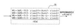
図8は、基準車体速再配分部35の構成を表すブロック図である。
図8に示すように、基準車体速再配分部35は、センサ3、4、11、12が出力する検出信号に基づいて、操舵角δf、δr、車体横速Vx、ヨーレイトγ等の物理量を読み込む。続いて、基準車体速再配分部35は、読み込んだ物理量、および路面外乱除去部34が出力する基準車体速成分Vb0に基づき、下記(5)式に従って基準車輪速成分ω0を算出する。FIG. 8 is a block diagram showing the configuration of the reference vehicle body
As shown in FIG. 8, the reference vehicle
ω0FL=[(Vb0FL―Tf/2・γ)cosδf+(Vx+Lf・γ)sinδf]/r0
ω0FR=[(Vb0FR+Tf/2・γ)cosδf+(Vx+Lf・γ)sinδf]/r0
ω0RL=[(Vb0RL―Tr/2・γ)cosδr+(Vx―Lr・γ)sinδr]/r0
ω0RR=[(Vb0RR―Tr/2・γ)cosδr+(Vx―Lr・γ)sinδr]/r0
・・・(5)
但し、r0は車輪14の半径である。
ここで、上記(5)式は、車両平面モデルである。ω0FL = [(Vb0FL−Tf / 2 · γ) cosδf + (Vx + Lf · γ) sinδf] / r0
ω0FR = [(Vb0FR + Tf / 2 · γ) cosδf + (Vx + Lf · γ) sinδf] / r0
ω0RL = [(Vb0RL−Tr / 2 · γ) cosδr + (Vx−Lr · γ) sinδr] / r0
ω0RR = [(Vb0RR−Tr / 2 · γ) cosδr + (Vx−Lr · γ) sinδr] / r0
... (5)
Where r0 is the radius of the
Here, the above equation (5) is a vehicle plane model.
なお、本実施形態では、平面運動除去後成分V0に基づいて基準車体速成分Vb0を算出する例を示したが、他の構成を採用してもよい。例えば、平面運動除去後成分V0に代えて、本実施形態の方法とは異なる方法で車両平面運動成分を除去した車体速、または車両平面運動成分を除去していない車体速である各輪車体速を用いてもよい。すなわち、車輪速ωsに基づいて車輪14それぞれの車体速である各輪車体速を算出し、算出した各輪車体速のうち、少なくとも2輪以上の各輪車体速に基づいて、路面外乱成分を除去した車体速の成分である基準車体速成分Vb0を算出する構成としてもよい。 In the present embodiment, the reference vehicle speed component Vb0 is calculated based on the post-planar motion removal component V0. However, other configurations may be adopted. For example, instead of the post-planar motion removal component V0, the vehicle body speed obtained by removing the vehicle planar motion component by a method different from the method of the present embodiment, or the vehicle body speed that is the vehicle speed not removing the vehicle planar motion component. May be used. That is, each wheel body speed which is the body speed of each
図4に戻り、加減算器28は、車輪速センサ2が出力する検出信号が表す車輪速ωs、および基準車輪速演算部27が出力する基準車輪速成分ω0に基づき、下記(6)式に従って車輪速変動成分ωd(=[ωdFL、ωdFR、ωdRL、ωdRR]T)を算出する。そして、加減算器28は、算出結果をジオメトリ変化上下成分変換部29に出力する。
ωd=ωs−ω0 ・・・(6)
ジオメトリ変化上下成分変換部29は、加減算器28が出力する車輪速変動成分ωdに基づいて、サスペンションのストローク速度Vz(=[VzFL、VzFR、VzRL、VzRR]T)を算出する。そして、ジオメトリ変化上下成分変換部29は、算出結果をストローク速度校正部30に出力する。Returning to FIG. 4, the adder /
ωd = ωs−ω0 (6)
Based on the wheel speed fluctuation component ωd output from the adder /
ストローク速度校正部30は、基準車輪速演算部27が算出した基準車輪速成分ω0に基づいて、ジオメトリ変化上下成分変換部29が算出したストローク速度Vzを校正する。そして、ストローク速度校正部30は、校正したストローク速度Vzを信号処理部32に出力する。ここで、ジオメトリ変化上下成分変換部29では、車輪速変動成分ωd、つまり、車輪速ωsと基準車輪速成分ω0との差に基づいてサスペンションのストローク速度Vzを算出している。それゆえ、サスペンションのストローク速度Vzは車輪速ωsに応じて分解能が変動する。そのため、基準車輪速成分ω0に応じてストローク速度Vzを校正することで、ストローク速度Vzの推定精度を向上できる。 The stroke
振動周波数演算部31は、基準車輪速演算部27が出力する基準車体速成分Vb0に基づき、下記(7)式に従って後述する帯域除去フィルタH(z)の目標周波数fc(=[fcFL、fcFR、fcRL、fcRR]T)を算出する。目標周波数fcとは、車輪速ωsが含んでいる成分のうち、帯域除去フィルタHによって除去する成分の周波数帯域を表す周波数である。そして、振動周波数演算部31は、算出結果を信号処理部32に出力する。
fc=Vb0/(2・π・r0) ・・・(7)
Vb0=[Vb0FL、Vb0FR、Vb0RL、Vb0RR]T
但し、r0は車輪14の半径である。Based on the reference vehicle speed component Vb0 output from the reference wheel
fc = Vb0 / (2.pi.r0) (7)
Vb0 = [Vb0FL, Vb0FR, Vb0RL, Vb0RR]T
Where r0 is the radius of the
例えば、車輪14では、車輪14(タイヤ、R/W、アクスル等)の回転に伴ってアンバランス振動が発生する。このアンバランス振動は、通常、車両品質基準内の比較的小さい振動となる。しかしながら、車輪速ωsからサスペンションのストローク速度Vzを算出する方法では、車両品質基準内のアンバランス振動であったとしても、車輪速ωsが変動すると、サスペンションのストローク速度Vzの推定精度が低下する。それゆえ、車輪14のアンバランス振動による成分を除去することで、ストローク速度Vzの推定精度を向上できる。そのため、目標周波数fcとしては、車輪速ωsが含んでいる成分のうち、車輪14の回転に伴って発生するアンバランス振動の周波数を設定する。 For example, in the
これにより、サスペンションのストローク速度Vzの推定精度を向上できる。
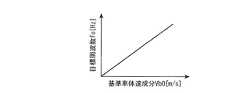
このように、本実施形態のサスペンション制御装置では、上記(7)式に示すように、基準車体速成分Vb0に比例させて目標周波数fcを設定する構成とした。それゆえ、アンバランス振動の周波数が基準車体速成分Vb0の増大に伴って増大するところ、図9に示すように、基準車体速成分Vb0が大きいほど目標周波数fcを大きくすることで、車輪14のアンバランス振動による成分を適切に除去できる。Thereby, the estimation accuracy of the stroke speed Vz of the suspension can be improved.
As described above, the suspension control device of the present embodiment is configured to set the target frequency fc in proportion to the reference vehicle body speed component Vb0, as shown in the above equation (7). Therefore, when the frequency of the unbalanced vibration increases as the reference vehicle body speed component Vb0 increases, the target frequency fc is increased as the reference vehicle body speed component Vb0 increases, as shown in FIG. The components due to unbalanced vibration can be removed appropriately.
また、基準車体速成分Vb0、つまり、車両平面運動成分および路面外乱成分を除去した車体速Vの成分に基づいて目標周波数fcを設定する構成とした。それゆえ、単に車体速Vに基づいて目標周波数fcを設定する方法と異なり、車両平面運動成分や路面外乱成分による目標周波数fcの変動を防止できる。そのため、ストローク速度Vzから外乱成分をより適切に除去できる。これにより、サスペンションのストローク速度Vz(後述するストローク速度推定値VzSH)の推定精度を向上できる。 Further, the target frequency fc is set based on the reference vehicle speed component Vb0, that is, the vehicle speed V component from which the vehicle plane motion component and the road disturbance component are removed. Therefore, unlike the method of simply setting the target frequency fc based on the vehicle body speed V, it is possible to prevent fluctuations in the target frequency fc due to vehicle plane motion components and road surface disturbance components. Therefore, the disturbance component can be more appropriately removed from the stroke speed Vz. Thereby, the estimation accuracy of the stroke speed Vz of the suspension (stroke speed estimated value VzSH described later) can be improved.
信号処理部32は、ストローク速度校正部30が出力するストローク速度Vz、および振動周波数演算部31が出力する目標周波数fcに基づき、下記(8)式に従ってストローク速度推定値VzSH(=[VzSHFL、VzSHFR、VzSHRL、VzSHRR]T)を算出する。ストローク速度推定値VzSHとは、ストローク速度Vzから目的とするサスペンションのストローク状態の制御に必要のないノイズ成分を除去した後のストローク速度である。ノイズ成分とは、ストローク速度Vzが含んでいる成分のうち目標周波数fcを含む周波数帯域、つまり、目標周波数fcおよびその周辺の周波数からなる周波数帯域(以下、除去対象周波数帯域とも呼ぶ)における成分である。そして、信号処理部32は、算出結果を制御信号変換部26に出力する。Based on the stroke speed Vz output from the stroke

P=[PFL、PFR、PRL、PRR]T=2・π・fc
但し、H(z)は帯域除去フィルタ、Pは極、Tはサンプル時間である。
ここで、図10に示すように、帯域除去フィルタH(z)は、除去対象周波数帯域の成分を除去可能なフィルタとなる。それゆえ、帯域除去フィルタH(z)は、サスペンションのストローク速度Vzから車輪14の回転に伴って発生するアンバランス振動による成分を除去できる。P = [PFL, PFR, PRL, PRR]T = 2 · π · fc
However, H (z) is a band elimination filter, P is a pole, and T is a sample time.
Here, as shown in FIG. 10, the band removal filter H (z) is a filter that can remove the component of the removal target frequency band. Therefore, the band elimination filter H (z) can remove a component due to unbalanced vibration generated with the rotation of the
また、帯域除去フィルタH(z)のQ値は、以下の手順に従って設定する。
まず、振動周波数演算部31は、走行路面の悪路の度合いを判定する。走行路面の悪路の度合いとしては、バネ上の上下方向の加速度が含んでいる成分の振幅の大きさを採用できる。また、車輪速ωsに基づいて算出した、車輪14におけるタイヤのねじり共振におけるゲインの大きさを採用できる。Further, the Q value of the band elimination filter H (z) is set according to the following procedure.
First, the vibration
続いて、振動周波数演算部31は、Q値設定用マップを参照し、走行路面の悪路の度合いの判定結果に対応するQ値を抽出する。Q値設定用マップとは、図11に示すように、走行路面の悪路の度合いを横軸とし、Q値を縦軸とするマップである。Q値設定用マップでは、走行路面の悪路の度合いが大きくなるほどQ値が小さな値となる。 Subsequently, the vibration
例えば、走行路面の悪路の度合いが高い場合には、悪路の度合いが低い場合に比べ、路面外乱振動成分が大きくなる。路面外乱振動成分とは、車輪速ωsが含む成分のうち、路面の凹凸等、路面状態によって発生するサスペンションのストロークに起因する成分である。それゆえ、走行路面の悪路の度合いが高い場合には、路面外乱振動成分よりも車輪回転振動成分が相対的に小さくなる。車輪回転振動成分とは、車輪速ωsが含む成分のうち、車輪14の回転に伴って発生するアンバランス振動による外乱成分である。つまり、車輪速センサ2の検出信号が含んでいる成分のうち、路面凹凸による成分よりも車輪14のアンバランス振動による外乱成分が相対的に小さくなる。そのため、図10に示すように、帯域除去フィルタH(z)のQ値を小さい値とすることで、帯域除去フィルタH(z)の除去性能を低下できる。すなわち、除去対象周波数帯域のゲインを増大させて「1」(0[dB])に近づけることができ、ストローク速度Vzの検出性能を向上できる。 For example, when the degree of the bad road on the traveling road surface is high, the road surface disturbance vibration component becomes larger than when the degree of the bad road is low. The road surface disturbance vibration component is a component caused by a suspension stroke generated by road surface conditions such as road surface unevenness among components included in the wheel speed ωs. Therefore, when the degree of bad road on the traveling road surface is high, the wheel rotational vibration component is relatively smaller than the road surface disturbance vibration component. The wheel rotation vibration component is a disturbance component due to unbalanced vibration generated with the rotation of the
また、例えば、走行路面の悪路の度合いが低い場合には、悪路の度合いが高い場合に比べ、路面外乱振動成分が小さくなる。それゆえ、走行路面の悪路の度合いが低い場合には、路面外乱振動成分よりも車輪回転振動成分が相対的に大きくなる。つまり、車輪速センサ2の検出信号が含んでいる成分のうち、路面凹凸による成分よりも車輪14のアンバランス振動による外乱成分が相対的に大きくなる。そのため、帯域除去フィルタH(z)のQ値を大きい値とすることで、帯域除去フィルタH(z)の除去性能を増大できる。すなわち、除去対象周波数帯域のゲインを低減させて「0」に近づけることができる。これにより、ストローク速度Vzからのノイズ除去性能を向上できる。 Further, for example, when the degree of bad road on the traveling road surface is low, the road surface disturbance vibration component is smaller than when the degree of bad road is high. Therefore, when the degree of the bad road on the traveling road surface is low, the wheel rotational vibration component is relatively larger than the road surface disturbance vibration component. That is, among the components included in the detection signal of the
図2に戻り、姿勢偏差演算部23は、目標値演算部21が出力する目標姿勢と、状態推定部22が出力する実姿勢との差である姿勢偏差を算出する(図3ステップS105)。そして、姿勢偏差演算部23は、算出結果をバネ上姿勢制御力演算部24に出力する。 Returning to FIG. 2, the posture
バネ上姿勢制御力演算部24は、目標値演算部21が算出した目標姿勢と実姿勢との間に仮想的に設定した減衰係数を有する。実姿勢とは、バネ上のロール運動、ピッチ運動およびバウンス運動の各運動自由度、またはバネ上の平面視で互いに異なる3箇所以上の位置における上下運動自由度の実際の姿勢である。そして、バネ上姿勢制御力演算部24は、減衰係数および姿勢偏差演算部23が出力する姿勢偏差に基づいて目標バネ上姿勢制御力Psを算出する(図3ステップS106)。目標バネ上姿勢制御力Psとは、目標姿勢を実現するためのショックアブソーバ13の減衰力(フィードバック値)である。そして、バネ上姿勢制御力演算部24は、算出結果を目標制御力マネジメント部25に出力する。 The sprung posture
目標制御力マネジメント部25は、目標値演算部21が出力する目標ドライバ制御力Pd、およびバネ上姿勢制御力演算部24が出力する目標バネ上姿勢制御力Psに基づき、下記(19)式に従って目標制御力(減衰力)を算出する(図3ステップS107)。そして、目標制御力マネジメント部25は、算出結果を制御信号変換部26に出力する。
目標制御力=Kd・Pd+K*・Ps ・・・(19)
但し、Kd、K*は、制御モード、運転者の車速に対する感覚、ロール運動方向、ピッチ運動方向、バウンス運動方向に対する振動感覚に基づいて、目標ドライバ制御力Pd、目標バネ上姿勢制御力Psを補正するための制御ゲイン、またはフィルタである。The target control
Target control force = Kd / Pd + K * / Ps (19)
However, Kd and K * are the target driver control force Pd and the target sprung posture control force Ps based on the control mode, the driver's sense of vehicle speed, the vibration direction of the roll motion direction, pitch motion direction, and bounce motion direction. It is a control gain or a filter for correcting.
制御信号変換部26は、目標制御力マネジメント部25が出力する目標制御力(減衰力)、および状態推定部22が出力するサスペンションストローク速度に基づき、指令信号マップからアクチュエータ指令信号を検索する(図3ステップS108)。指令信号マップとは、目標制御力およびサスペンションストローク速度の組み合わせ毎に当該組み合わせに応じたアクチュエータ指令信号をマッピングしたマップである。また、アクチュエータ指令信号とは、ショックアブソーバ13のオリフィスの大きさが目標状態となるように、アクチュエータ15を制御するための信号である。なお、本実施形態では、アクチュエータ指令信号を出力する例を示したが、他の構成を採用することもできる。例えば、アクチュエータ15を制御するための指令電流を出力するようにしてもよい。 The control
(動作その他)
次に、車両Aのサスペンション制御装置の動作について説明する。
旋回うねり路の走行中、車両Aの三次元運動に起因して、車輪速センサ2が検出する車輪速ωsに車両平面運動成分および外乱成分が混入したとする。すると、制御装置20が、車輪速ωs、運転者の操作量(操舵角)δf、δr、車両Aの状態量Vx、γに基づき、車両平面モデルの逆モデルを用いて、混入した車両平面運動成分を除去した車体速の成分である平面運動除去後成分V0を算出する(図5の平面運動成分抽出部33)。(Operation other)
Next, the operation of the suspension control device for vehicle A will be described.
It is assumed that the vehicle plane motion component and the disturbance component are mixed into the wheel speed ωs detected by the
続いて、制御装置20が、算出した平面運動除去後成分V0に基づいて、車両平面運動成分および路面外乱成分を除去した車体速の成分である基準車輪速成分ω0を算出する(図5の路面外乱除去部34、基準車体速再配分部35)。続いて、制御装置20が、算出した基準車輪速成分ω0に基づき、車輪14の回転に伴って発生するアンバランス振動の周波数を目標周波数fcとして算出する(図4の振動周波数演算部31)。続いて、制御装置20が、算出した目標周波数fcおよびストローク速度Vzに基づき、目標周波数fcおよびその周辺の周波数からなる周波数帯域の成分を除去する帯域除去フィルタH(z)に従ってストローク速度推定値VzSHを算出する(図4の信号処理部32)。これにより、サスペンションのストローク速度Vzからアンバランス振動による成分を除去する。 Subsequently, the
このように、本実施形態のサスペンション制御装置では、車両平面運動成分および路面外乱成分を除去した車輪速の成分である基準車体速成分Vb0を算出する。続いて、算出した基準車体速成分Vb0に基づいて基準車輪速成分ω0を算出する。続いて、算出した基準車輪速成分ω0に基づいて目標周波数fcを設定する。続いて、サスペンションのストローク速度Vzから目標周波数fcおよびその周辺の周波数からなる周波数帯域の成分(外乱成分)を除去する。それゆえ、ストローク速度Vzから車輪14のアンバランス振動による成分を除去できる。そのため、ストローク速度Vzの推定精度を向上できる。 As described above, the suspension control apparatus according to the present embodiment calculates the reference vehicle body speed component Vb0 that is the wheel speed component from which the vehicle plane motion component and the road surface disturbance component are removed. Subsequently, a reference wheel speed component ω0 is calculated based on the calculated reference vehicle body speed component Vb0. Subsequently, the target frequency fc is set based on the calculated reference wheel speed component ω0. Subsequently, the frequency band component (disturbance component) composed of the target frequency fc and the surrounding frequencies is removed from the stroke speed Vz of the suspension. Therefore, the component due to the unbalanced vibration of the
また、本実施形態のサスペンション制御装置では、基準車体速成分Vb0、つまり、車両平面運動成分および路面外乱成分を除去した車体速Vの成分に基づいて目標周波数fcを設定する。それゆえ、単に車体速Vに基づいて目標周波数fcを設定する方法と異なり、車両平面運動成分や路面外乱成分による目標周波数fcの変動を防止できる。そのため、ストローク速度Vzから外乱成分をより適切に除去できる。これにより、サスペンションのストローク速度Vz(ストローク速度推定値VzSH)の推定精度を向上できる。 In the suspension control apparatus of the present embodiment, the target frequency fc is set based on the reference vehicle body speed component Vb0, that is, the vehicle body speed V component from which the vehicle plane motion component and the road surface disturbance component are removed. Therefore, unlike the method of simply setting the target frequency fc based on the vehicle body speed V, it is possible to prevent fluctuations in the target frequency fc due to vehicle plane motion components and road surface disturbance components. Therefore, the disturbance component can be more appropriately removed from the stroke speed Vz. Thereby, the estimation accuracy of the stroke speed Vz of the suspension (stroke speed estimated value VzSH) can be improved.
ここで、車両Aが、路面凹凸等による路面入力が大きい悪路を走行していたとする。すると、制御装置20が、走行路面の悪路の度合いが高いと判定し、帯域除去フィルタH(z)のQ値を比較的大きい値とする(図4の振動周波数演算部31)。これにより、帯域除去フィルタH(z)の除去性能を増大し、ストローク速度Vzの成分のうち路面外乱振動成分を適切に除去し、アンバランス振動による成分の除去性能を向上させる。 Here, it is assumed that the vehicle A is traveling on a rough road with a large road surface input due to road surface unevenness or the like. Then, the
一方、車両Aが、路面入力が微少である良路を走行していたとする。すると、制御装置20が、走行路面の悪路の度合いが低いと判定し、帯域除去フィルタH(z)のQ値を比較的小さい値とする(図4の振動周波数演算部31)。これにより、帯域除去フィルタH(z)の除去性能を低減し、ストローク速度Vzの成分のうちサスペンションストロークに基づく成分の除去を回避し、ストローク速度Vzの検出性能を向上させる。 On the other hand, it is assumed that the vehicle A is traveling on a good road where the road surface input is very small. Then, the
続いて、制御装置20が、算出したストローク速度推定値VzSHに基づいてショックアブソーバ13の減衰力を性御する指令をアクチュエータ15に出力する(図2の制御信号変換部26)。そして、ストローク速度やストローク量等、サスペンションのストローク状態を制御する。これにより、目標制御力(減衰力)を発生させる。
このように、本実施形態のサスペンション制御装置では、ストローク速度Vzから車輪14のアンバランス振動による成分を除去できる。それゆえ、ストローク速度Vzの推定精度を向上できる。そのため、車両Aの乗り心地を向上できる。Subsequently, the
Thus, in the suspension control device of the present embodiment, the component due to the unbalanced vibration of the
なお、一般に、良路のように路面入力が微少である路面を走行している場合、車輪速ωsから推定したストローク速度Vzには、車輪回転振動成分がほとんどを占めることになる。また、車輪回転振動成分は、周期的に正値と負値とをとる。それゆえ、車輪回転振動成分が混入したストローク速度Vzの推定結果には、符号反転が頻繁に発生する。そのため、ストローク速度Vzの推定結果をそのままサスペンションのストローク状態の制御に用いる方法では、サスペンション制御の制御力が変動し、乗り心地が悪化する。 In general, when the vehicle is traveling on a road surface with a small road surface input such as a good road, the wheel rotational vibration component occupies most of the stroke speed Vz estimated from the wheel speed ωs. The wheel rotation vibration component periodically takes a positive value and a negative value. Therefore, sign inversion frequently occurs in the estimation result of the stroke speed Vz in which the wheel rotational vibration component is mixed. For this reason, in the method in which the estimation result of the stroke speed Vz is used as it is for controlling the stroke state of the suspension, the control force of the suspension control fluctuates and the riding comfort deteriorates.
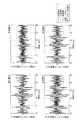
図12は、車両Aのサスペンション制御装置の実験結果を表すタイムチャートである。
図12に示すように、本実験では、本実施形態のサスペンション制御装置で算出したストローク速度推定値VzSHと、比較例1、2の方法で算出したストローク速度との比較を行った。比較例1の方法とは、バネ下に配設した加速度センサを用いてサスペンションのストローク速度を算出する方法である。比較例2の方法とは、ストロークセンサを用いてサスペンションのストローク速度を算出する方法である。この実験によれば、本実施形態のサスペンション制御装置で算出したストローク速度推定値VzSHは、比較例1、2の方法で算出したストローク速度と同等の推定精度となることが確認できた。FIG. 12 is a time chart showing experimental results of the suspension control apparatus for vehicle A.
As shown in FIG. 12, in this experiment, the stroke speed estimated value VzSH calculated by the suspension control device of the present embodiment was compared with the stroke speed calculated by the methods of Comparative Examples 1 and 2. The method of Comparative Example 1 is a method of calculating the suspension stroke speed using an acceleration sensor disposed under the spring. The method of Comparative Example 2 is a method of calculating the stroke speed of the suspension using a stroke sensor. According to this experiment, it was confirmed that the estimated stroke speed value VzSH calculated by the suspension control device of the present embodiment has an estimation accuracy equivalent to the stroke speed calculated by the methods of Comparative Examples 1 and 2.
なお、図13に示すように、ストローク速度Vzと、比較例1、2の方法で算出したストローク速度との比較も行った。この比較によれば、ストローク速度Vzは、比較例1、2の方法で算出したストローク速度よりも推定精度が低下することが確認できた。したがって、本実施形態のサスペンション制御装置で算出したストローク速度推定値VzSHは、ストローク速度Vzよりも推定精度が高いことが確認できた。 In addition, as shown in FIG. 13, the stroke speed Vz was compared with the stroke speed calculated by the methods of Comparative Examples 1 and 2. According to this comparison, it was confirmed that the estimation accuracy of the stroke speed Vz was lower than the stroke speed calculated by the methods of Comparative Examples 1 and 2. Therefore, it was confirmed that the estimated stroke speed value VzSH calculated by the suspension control device of the present embodiment has higher estimation accuracy than the stroke speed Vz.
本実施形態では、図1の車輪速センサ2が車輪速検出部を構成する。以下同様に、図1の制御装置20、図2の状態推定部22、図4の基準車輪速演算部27、および図5の平面運動成分抽出部33、路面外乱除去部34、基準車体速再配分部35がストローク速度算出部を構成する。さらに、ストローク速度推定値VzSHが除去後成分を構成する。また、目標周波数fcを含む周波数帯域(目標周波数fcおよびその周辺の周波数からなる周波数帯域)が設定周波数帯域を構成する。さらに、図1の制御装置20、図2の状態推定部22、および図4の信号処理部32が設定周波数帯域除去部を構成する。また、図1のアクチュエータ15、制御装置20、および図2の制御信号変換部26がストローク状態制御部を構成する。さらに、図1の制御装置20、図2の状態推定部22、および図4の振動周波数演算部31が設定部を構成する。また、図5の平面運動成分抽出部33が平面運動成分除去部を構成する。さらに、路面外乱除去部34が路面外乱除去部を構成する。また、図1の制御装置20、図2の状態推定部22、および図4の信号処理部32が走行路面判定部を構成する。 In this embodiment, the
(本実施形態の効果)
本実施形態は、次のような効果を奏する。
(1)制御装置20が、基準車体速成分Vb0に基づいて目標周波数fcを設定する。続いて、制御装置20が、サスペンションのストローク速度Vzから目標周波数fcを含む周波数帯域の成分を除去する。また、制御装置20が、除去後のストローク速度Vz(ストローク速度推定値VzSH)に基づいて、サスペンションのストローク状態を制御する。
このような構成によれば、サスペンションのストローク速度Vzから目標周波数fcを含む周波数帯域に存在する外乱成分を除去できる。これにより、サスペンションのストローク速度Vz(ストローク速度推定値VzSH)の推定精度を向上できる。(Effect of this embodiment)
This embodiment has the following effects.
(1) The
According to such a configuration, it is possible to remove disturbance components existing in a frequency band including the target frequency fc from the suspension stroke speed Vz. Thereby, the estimation accuracy of the stroke speed Vz of the suspension (stroke speed estimated value VzSH) can be improved.
(2)基準車体速成分Vb0は、車輪速ωsから車両平面運動成分および路面外乱成分を除去して得た車体速である。
このような構成によれば、車両平面運動成分や路面外乱成分による目標周波数fcの変動を防止でき、ストローク速度Vzから外乱成分をより適切に除去できる。これにより、ストローク速度Vz(ストローク速度推定値VzSH)の推定精度をより向上できる。(2) The reference vehicle speed component Vb0 is a vehicle speed obtained by removing the vehicle plane motion component and the road surface disturbance component from the wheel speed ωs.
According to such a configuration, fluctuations in the target frequency fc due to vehicle plane motion components and road surface disturbance components can be prevented, and disturbance components can be more appropriately removed from the stroke speed Vz. Thereby, the estimation accuracy of the stroke speed Vz (stroke speed estimated value VzSH) can be further improved.
(3)制御装置20が、車輪速ωsから車両平面運動成分を除去して平面運動除去後成分V0を算出する。続いて、制御装置20が、算出した平面運動除去後成分V0から路面外乱成分を除去して基準車体速成分Vb0を算出する。
このような構成によれば、車両平面運動成分を除去した後に路面外乱成分を除去する。それゆえ、車両平面運動成分および路面外乱成分を比較的容易に除去できる。(3) The
According to such a configuration, the road surface disturbance component is removed after the vehicle plane motion component is removed. Therefore, the vehicle plane motion component and the road surface disturbance component can be removed relatively easily.
(4)車両平面運動成分は、車輪速ωsが含む成分のうち、操舵角δf、δrおよびヨーレイトγに起因する成分である。
このような構成によれば、車輪速ωsから、操舵角δf、δrおよびヨーレイトγに起因する成分を除去することができる。これにより、操舵角δf、δrおよびヨーレイトγに起因する目標周波数fcの変動を防止できる。(4) The vehicle plane motion component is a component caused by the steering angles δf and δr and the yaw rate γ among the components included in the wheel speed ωs.
According to such a configuration, components caused by the steering angles δf and δr and the yaw rate γ can be removed from the wheel speed ωs. Thereby, fluctuations in the target frequency fc caused by the steering angles δf and δr and the yaw rate γ can be prevented.
(5)路面外乱成分は、車輪速ωsが含む成分のうち、路面状態によって発生した車両Aのロール運動およびピッチ運動に起因する成分である。
このような構成によれば、車輪速ωsから、車両Aのロール運動およびピッチ運動に起因する成分を除去することができる。これにより、車両Aのロール運動およびピッチ運動に起因する目標周波数fcの変動を防止できる。(5) The road surface disturbance component is a component caused by the roll motion and the pitch motion of the vehicle A generated by the road surface state among the components included in the wheel speed ωs.
According to such a configuration, components caused by the roll motion and pitch motion of the vehicle A can be removed from the wheel speed ωs. Thereby, the fluctuation | variation of the target frequency fc resulting from the roll motion and pitch motion of the vehicle A can be prevented.
(6)制御装置20が、走行路面の悪路の度合いを判定し、判定結果に応じて、帯域除去フィルタH(z)の除去特性を設定する。
この構成によれば、例えば、車輪回転振動成分が路面外乱振動成分より大きく、走行路面の悪路の度合いが低い(良路)と判定した場合、除去特性を増大できる。また、例えば、車輪回転振動成分が路面外乱振動成分より小さく、走行路面の悪路の度合いが高いと判定した場合、除去特性を低減できる。これにより、車輪回転振動成分による影響を低減しつつ、路面外乱振動成分によるサスペンションストロークを適切に検出できる。(6) The
According to this configuration, for example, when it is determined that the wheel rotational vibration component is larger than the road surface disturbance vibration component and the degree of the rough road on the traveling road surface is low (good road), the removal characteristics can be increased. For example, when it is determined that the wheel rotation vibration component is smaller than the road disturbance vibration component and the degree of the bad road on the traveling road surface is high, the removal characteristic can be reduced. Thereby, it is possible to appropriately detect the suspension stroke due to the road surface disturbance vibration component while reducing the influence of the wheel rotation vibration component.
2は車輪速センサ(車輪速検出部)
15はアクチュエータ(ストローク状態制御部)
20は制御装置(ストローク速度算出部、設定部、設定周波数帯域除去部、ストローク状態制御部、走行路面判定部)
22は状態推定部(設定部、設定周波数帯域除去部、走行路面判定部)
26は制御信号変換部(ストローク状態制御部)
31は振動周波数演算部(設定部)
32は信号処理部(設定周波数帯域除去部、走行路面判定部)
33は平面運動成分抽出部(ストローク速度算出部、平面運動成分除去部)
34は路面外乱成分除去部(ストローク速度算出部、路面外乱除去部)
35は基準車体速再配分部(ストローク速度算出部)2 is a wheel speed sensor (wheel speed detector).
15 is an actuator (stroke state control unit)
20 is a control device (stroke speed calculation unit, setting unit, set frequency band removal unit, stroke state control unit, traveling road surface determination unit)
22 is a state estimation unit (setting unit, set frequency band removal unit, traveling road surface determination unit)
26 is a control signal converter (stroke state controller)
31 is a vibration frequency calculation part (setting part).
32 is a signal processing unit (set frequency band removing unit, traveling road surface determining unit).
33 is a plane motion component extraction unit (stroke speed calculation unit, plane motion component removal unit)
34 is a road surface disturbance component removing unit (stroke speed calculating unit, road surface disturbance removing unit).
35 is a reference vehicle speed redistribution unit (stroke speed calculation unit).
Claims (4)
Translated fromJapanese前記車輪速検出部が検出した前記車輪速に基づいて、サスペンションのストローク速度を算出するストローク速度算出部と、
前記ストローク速度算出部が算出した前記サスペンションのストローク速度から、設定した設定周波数帯域の成分を除去した後のストローク速度の成分である除去後成分を算出する設定周波数帯域成分除去部と、
前記設定周波数帯域成分除去部で算出した前記除去後成分に基づいて、前記サスペンションのストローク状態を制御するストローク状態制御部と、
前記車輪速検出部が検出した前記車輪速に基づいて、基準車体速成分を算出する基準車体速成分算出部と、
前記基準車体速成分算出部が算出した前記基準車体速成分に基づいて前記設定周波数帯域を設定する設定部と、を備え、
前記基準車体速成分は、車両平面運動成分および路面外乱成分を除去した車体速の成分であり、
前記ストローク状態制御部は、
前記車輪速検出部が検出した前記車輪速から前記車両平面運動成分を除去して平面運動除去後成分を算出する平面運動成分除去部と、
前記平面運動成分除去部が算出した前記平面運動除去後成分から前記路面外乱成分を除去して前記基準車体速成分を算出する路面外乱除去部と、を備えたことを特徴とするサスペンション制御装置。A wheel speed detector for detecting wheel speed;
Based on the wheel speed detected by the wheel speed detection unit, a stroke speed calculation unit that calculates a stroke speed of the suspension;
A set frequency band component removing unit that calculates a post-removal component that is a component of the stroke speed after removing the set frequency band component from the suspension stroke speed calculated by the stroke speed calculating unit;
A stroke state control unit that controls a stroke state of the suspension based on the post-removal component calculated by the set frequency band component removing unit;
A reference vehicle body speed component calculation unit that calculates a reference vehicle body speed component based on the wheel speed detected by the wheel speed detection unit;
A setting unit that sets the set frequency band based on the reference vehicle speed component calculated by the reference vehicle speed component calculation unit,
The reference vehicle speed component is a vehicle speed component obtained by removing a vehicle plane motion component and a road surface disturbance component,
The stroke state control unit
A plane motion component removing unit that calculates the post-planar motion removal component by removing the vehicle plane motion component from the wheel speed detected by the wheel speed detection unit;
A suspension control apparatus, comprising: a road surface disturbance removing unit that calculates the reference vehicle body speed component by removing the road surface disturbance component from the post-planar movement removed component calculated by the planar movement component removing unit.
前記設定周波数帯域成分除去部は、前記走行路面判定部による判定結果に応じて、前記設定周波数帯域の成分の除去特性を設定することを特徴とする請求項1から3のいずれか1項に記載のサスペンション制御装置。A traveling road surface determination unit that determines the degree of bad road on the traveling road surface,
The said setting frequency band component removal part sets the removal characteristic of the component of the said setting frequency band according to the determination result by the said traveling road surface determination part, The anyone of Claim1 to 3 characterized by the above-mentioned. Suspension control device.
Priority Applications (2)
| Application Number | Priority Date | Filing Date | Title |
|---|---|---|---|
| JP2012228279AJP6070044B2 (en) | 2011-10-26 | 2012-10-15 | Suspension control device |
| PCT/JP2012/077408WO2013061983A1 (en) | 2011-10-26 | 2012-10-24 | Suspension control device and suspension control method |
Applications Claiming Priority (3)
| Application Number | Priority Date | Filing Date | Title |
|---|---|---|---|
| JP2011235238 | 2011-10-26 | ||
| JP2011235238 | 2011-10-26 | ||
| JP2012228279AJP6070044B2 (en) | 2011-10-26 | 2012-10-15 | Suspension control device |
Publications (2)
| Publication Number | Publication Date |
|---|---|
| JP2013107628A JP2013107628A (en) | 2013-06-06 |
| JP6070044B2true JP6070044B2 (en) | 2017-02-01 |
Family
ID=48167810
Family Applications (1)
| Application Number | Title | Priority Date | Filing Date |
|---|---|---|---|
| JP2012228279AActiveJP6070044B2 (en) | 2011-10-26 | 2012-10-15 | Suspension control device |
Country Status (2)
| Country | Link |
|---|---|
| JP (1) | JP6070044B2 (en) |
| WO (1) | WO2013061983A1 (en) |
Families Citing this family (7)
| Publication number | Priority date | Publication date | Assignee | Title |
|---|---|---|---|---|
| JP6369020B2 (en)* | 2013-12-24 | 2018-08-08 | 日産自動車株式会社 | Vehicle control device |
| JP6285591B1 (en) | 2017-03-24 | 2018-02-28 | 株式会社ショーワ | Suspension control device and suspension device |
| JP6273059B1 (en) | 2017-03-24 | 2018-01-31 | 株式会社ショーワ | Vehicle control device and vehicle |
| JP6285592B1 (en)* | 2017-03-24 | 2018-02-28 | 株式会社ショーワ | Road surface determination device, suspension control device, and suspension device |
| JP6279121B1 (en) | 2017-03-24 | 2018-02-14 | 株式会社ショーワ | Control device and steering device |
| JP6359163B1 (en)* | 2017-08-03 | 2018-07-18 | 株式会社ショーワ | Suspension control device and suspension device |
| JP2022093081A (en)* | 2020-12-11 | 2022-06-23 | 本田技研工業株式会社 | Electric suspension device |
Family Cites Families (6)
| Publication number | Priority date | Publication date | Assignee | Title |
|---|---|---|---|---|
| JP2541635B2 (en)* | 1988-09-30 | 1996-10-09 | 日産自動車株式会社 | Active suspension |
| JP5021348B2 (en)* | 2007-03-27 | 2012-09-05 | 本田技研工業株式会社 | Control device for damping force variable damper |
| JP5158333B2 (en)* | 2007-09-28 | 2013-03-06 | 日立オートモティブシステムズ株式会社 | Suspension control device |
| JP5224039B2 (en)* | 2008-03-31 | 2013-07-03 | 日立オートモティブシステムズ株式会社 | Suspension control device |
| JP2010247631A (en)* | 2009-04-15 | 2010-11-04 | Nissan Motor Co Ltd | Vehicle control device |
| JP2011106941A (en)* | 2009-11-17 | 2011-06-02 | Toyota Motor Corp | Device and method for detecting wheel speed |
- 2012
- 2012-10-15JPJP2012228279Apatent/JP6070044B2/enactiveActive
- 2012-10-24WOPCT/JP2012/077408patent/WO2013061983A1/ennot_activeCeased
Also Published As
| Publication number | Publication date |
|---|---|
| JP2013107628A (en) | 2013-06-06 |
| WO2013061983A1 (en) | 2013-05-02 |
Similar Documents
| Publication | Publication Date | Title |
|---|---|---|
| JP6070044B2 (en) | Suspension control device | |
| US8649938B2 (en) | System, program product, and method for dynamic control of vehicle | |
| KR101470221B1 (en) | Apparatus for controlling suspension and method thereof | |
| US10703162B2 (en) | Suspension control system | |
| JP5983597B2 (en) | Vehicle state estimation device, vehicle state estimation method, and vehicle control device | |
| CN107010068B (en) | The driving-force control apparatus of vehicle | |
| CN104908548B (en) | Vehicle-state estimating device, controller of vehicle and vehicle-state presumption method | |
| JP5370494B2 (en) | Vehicle control device | |
| KR20160044362A (en) | Method for controlling suspension system | |
| US7406372B2 (en) | Method for controlling variable damper in vehicle | |
| WO2024259904A1 (en) | Traveling slope estimation method and apparatus for vehicle, and device, storage medium and program | |
| JP2008522886A (en) | Apparatus and method for determining height of center of gravity of vehicle | |
| US20190001781A1 (en) | Traveling control system for vehicle | |
| JP2007161013A (en) | Wheel vertical acceleration detection device for posture correction of detection value of vertical acceleration sensor | |
| JP2020117196A (en) | Vehicle motion state estimation device | |
| JP5776375B2 (en) | Suspension control device | |
| CN103182915A (en) | Correction method for acceleration integral curve, suspension control system and control method | |
| JP5692516B2 (en) | Vehicle slip angle estimation device and vehicle attitude control device | |
| JP2011106941A (en) | Device and method for detecting wheel speed | |
| JP5326562B2 (en) | Turning behavior detection device, turning behavior detection method, and yaw rate estimation method | |
| JP5776374B2 (en) | Suspension control device | |
| JP2020185940A (en) | Vehicle motion state estimation device and vehicle motion state estimation method | |
| JP5157683B2 (en) | Suspension control device | |
| US20250121878A1 (en) | Apparatus and Method of Compensating an Oscillation in a Steering System Without a Mechanical Connection Between the Control Unit and the Steered Wheels | |
| JP5104594B2 (en) | Vehicle control device |
Legal Events
| Date | Code | Title | Description |
|---|---|---|---|
| A621 | Written request for application examination | Free format text:JAPANESE INTERMEDIATE CODE: A621 Effective date:20150828 | |
| A131 | Notification of reasons for refusal | Free format text:JAPANESE INTERMEDIATE CODE: A131 Effective date:20160802 | |
| A521 | Written amendment | Free format text:JAPANESE INTERMEDIATE CODE: A523 Effective date:20160916 | |
| TRDD | Decision of grant or rejection written | ||
| A01 | Written decision to grant a patent or to grant a registration (utility model) | Free format text:JAPANESE INTERMEDIATE CODE: A01 Effective date:20161206 | |
| A61 | First payment of annual fees (during grant procedure) | Free format text:JAPANESE INTERMEDIATE CODE: A61 Effective date:20161219 | |
| R151 | Written notification of patent or utility model registration | Ref document number:6070044 Country of ref document:JP Free format text:JAPANESE INTERMEDIATE CODE: R151 |