JP6067211B2 - Non-contact power feeding device - Google Patents
Non-contact power feeding deviceDownload PDFInfo
- Publication number
- JP6067211B2 JP6067211B2JP2011118663AJP2011118663AJP6067211B2JP 6067211 B2JP6067211 B2JP 6067211B2JP 2011118663 AJP2011118663 AJP 2011118663AJP 2011118663 AJP2011118663 AJP 2011118663AJP 6067211 B2JP6067211 B2JP 6067211B2
- Authority
- JP
- Japan
- Prior art keywords
- coil
- power
- foreign object
- power transmission
- unit
- Prior art date
- Legal status (The legal status is an assumption and is not a legal conclusion. Google has not performed a legal analysis and makes no representation as to the accuracy of the status listed.)
- Active
Links
Images


Classifications
- H—ELECTRICITY
- H04—ELECTRIC COMMUNICATION TECHNIQUE
- H04B—TRANSMISSION
- H04B5/00—Near-field transmission systems, e.g. inductive or capacitive transmission systems
- H04B5/70—Near-field transmission systems, e.g. inductive or capacitive transmission systems specially adapted for specific purposes
- H04B5/79—Near-field transmission systems, e.g. inductive or capacitive transmission systems specially adapted for specific purposes for data transfer in combination with power transfer
- B—PERFORMING OPERATIONS; TRANSPORTING
- B60—VEHICLES IN GENERAL
- B60L—PROPULSION OF ELECTRICALLY-PROPELLED VEHICLES; SUPPLYING ELECTRIC POWER FOR AUXILIARY EQUIPMENT OF ELECTRICALLY-PROPELLED VEHICLES; ELECTRODYNAMIC BRAKE SYSTEMS FOR VEHICLES IN GENERAL; MAGNETIC SUSPENSION OR LEVITATION FOR VEHICLES; MONITORING OPERATING VARIABLES OF ELECTRICALLY-PROPELLED VEHICLES; ELECTRIC SAFETY DEVICES FOR ELECTRICALLY-PROPELLED VEHICLES
- B60L53/00—Methods of charging batteries, specially adapted for electric vehicles; Charging stations or on-board charging equipment therefor; Exchange of energy storage elements in electric vehicles
- B60L53/10—Methods of charging batteries, specially adapted for electric vehicles; Charging stations or on-board charging equipment therefor; Exchange of energy storage elements in electric vehicles characterised by the energy transfer between the charging station and the vehicle
- B60L53/12—Inductive energy transfer
- B60L53/124—Detection or removal of foreign bodies
- B—PERFORMING OPERATIONS; TRANSPORTING
- B60—VEHICLES IN GENERAL
- B60L—PROPULSION OF ELECTRICALLY-PROPELLED VEHICLES; SUPPLYING ELECTRIC POWER FOR AUXILIARY EQUIPMENT OF ELECTRICALLY-PROPELLED VEHICLES; ELECTRODYNAMIC BRAKE SYSTEMS FOR VEHICLES IN GENERAL; MAGNETIC SUSPENSION OR LEVITATION FOR VEHICLES; MONITORING OPERATING VARIABLES OF ELECTRICALLY-PROPELLED VEHICLES; ELECTRIC SAFETY DEVICES FOR ELECTRICALLY-PROPELLED VEHICLES
- B60L53/00—Methods of charging batteries, specially adapted for electric vehicles; Charging stations or on-board charging equipment therefor; Exchange of energy storage elements in electric vehicles
- B60L53/10—Methods of charging batteries, specially adapted for electric vehicles; Charging stations or on-board charging equipment therefor; Exchange of energy storage elements in electric vehicles characterised by the energy transfer between the charging station and the vehicle
- B60L53/12—Inductive energy transfer
- B60L53/126—Methods for pairing a vehicle and a charging station, e.g. establishing a one-to-one relation between a wireless power transmitter and a wireless power receiver
- H—ELECTRICITY
- H01—ELECTRIC ELEMENTS
- H01F—MAGNETS; INDUCTANCES; TRANSFORMERS; SELECTION OF MATERIALS FOR THEIR MAGNETIC PROPERTIES
- H01F27/00—Details of transformers or inductances, in general
- H01F27/34—Special means for preventing or reducing unwanted electric or magnetic effects, e.g. no-load losses, reactive currents, harmonics, oscillations, leakage fields
- H01F27/36—Electric or magnetic shields or screens
- H01F27/363—Electric or magnetic shields or screens made of electrically conductive material
- H—ELECTRICITY
- H01—ELECTRIC ELEMENTS
- H01F—MAGNETS; INDUCTANCES; TRANSFORMERS; SELECTION OF MATERIALS FOR THEIR MAGNETIC PROPERTIES
- H01F38/00—Adaptations of transformers or inductances for specific applications or functions
- H01F38/14—Inductive couplings
- H—ELECTRICITY
- H02—GENERATION; CONVERSION OR DISTRIBUTION OF ELECTRIC POWER
- H02J—CIRCUIT ARRANGEMENTS OR SYSTEMS FOR SUPPLYING OR DISTRIBUTING ELECTRIC POWER; SYSTEMS FOR STORING ELECTRIC ENERGY
- H02J50/00—Circuit arrangements or systems for wireless supply or distribution of electric power
- H02J50/10—Circuit arrangements or systems for wireless supply or distribution of electric power using inductive coupling
- H—ELECTRICITY
- H02—GENERATION; CONVERSION OR DISTRIBUTION OF ELECTRIC POWER
- H02J—CIRCUIT ARRANGEMENTS OR SYSTEMS FOR SUPPLYING OR DISTRIBUTING ELECTRIC POWER; SYSTEMS FOR STORING ELECTRIC ENERGY
- H02J50/00—Circuit arrangements or systems for wireless supply or distribution of electric power
- H02J50/60—Circuit arrangements or systems for wireless supply or distribution of electric power responsive to the presence of foreign objects, e.g. detection of living beings
- H—ELECTRICITY
- H02—GENERATION; CONVERSION OR DISTRIBUTION OF ELECTRIC POWER
- H02J—CIRCUIT ARRANGEMENTS OR SYSTEMS FOR SUPPLYING OR DISTRIBUTING ELECTRIC POWER; SYSTEMS FOR STORING ELECTRIC ENERGY
- H02J50/00—Circuit arrangements or systems for wireless supply or distribution of electric power
- H02J50/70—Circuit arrangements or systems for wireless supply or distribution of electric power involving the reduction of electric, magnetic or electromagnetic leakage fields
- B—PERFORMING OPERATIONS; TRANSPORTING
- B60—VEHICLES IN GENERAL
- B60M—POWER SUPPLY LINES, AND DEVICES ALONG RAILS, FOR ELECTRICALLY- PROPELLED VEHICLES
- B60M7/00—Power lines or rails specially adapted for electrically-propelled vehicles of special types, e.g. suspension tramway, ropeway, underground railway
- H—ELECTRICITY
- H02—GENERATION; CONVERSION OR DISTRIBUTION OF ELECTRIC POWER
- H02J—CIRCUIT ARRANGEMENTS OR SYSTEMS FOR SUPPLYING OR DISTRIBUTING ELECTRIC POWER; SYSTEMS FOR STORING ELECTRIC ENERGY
- H02J2310/00—The network for supplying or distributing electric power characterised by its spatial reach or by the load
- H02J2310/40—The network being an on-board power network, i.e. within a vehicle
- H02J2310/48—The network being an on-board power network, i.e. within a vehicle for electric vehicles [EV] or hybrid vehicles [HEV]
- H—ELECTRICITY
- H02—GENERATION; CONVERSION OR DISTRIBUTION OF ELECTRIC POWER
- H02J—CIRCUIT ARRANGEMENTS OR SYSTEMS FOR SUPPLYING OR DISTRIBUTING ELECTRIC POWER; SYSTEMS FOR STORING ELECTRIC ENERGY
- H02J7/00—Circuit arrangements for charging or depolarising batteries or for supplying loads from batteries
- H02J7/00032—Circuit arrangements for charging or depolarising batteries or for supplying loads from batteries characterised by data exchange
- H02J7/00034—Charger exchanging data with an electronic device, i.e. telephone, whose internal battery is under charge
- H—ELECTRICITY
- H04—ELECTRIC COMMUNICATION TECHNIQUE
- H04B—TRANSMISSION
- H04B5/00—Near-field transmission systems, e.g. inductive or capacitive transmission systems
- H04B5/20—Near-field transmission systems, e.g. inductive or capacitive transmission systems characterised by the transmission technique; characterised by the transmission medium
- H04B5/24—Inductive coupling
- H04B5/26—Inductive coupling using coils
- H04B5/263—Multiple coils at either side
- Y—GENERAL TAGGING OF NEW TECHNOLOGICAL DEVELOPMENTS; GENERAL TAGGING OF CROSS-SECTIONAL TECHNOLOGIES SPANNING OVER SEVERAL SECTIONS OF THE IPC; TECHNICAL SUBJECTS COVERED BY FORMER USPC CROSS-REFERENCE ART COLLECTIONS [XRACs] AND DIGESTS
- Y02—TECHNOLOGIES OR APPLICATIONS FOR MITIGATION OR ADAPTATION AGAINST CLIMATE CHANGE
- Y02T—CLIMATE CHANGE MITIGATION TECHNOLOGIES RELATED TO TRANSPORTATION
- Y02T10/00—Road transport of goods or passengers
- Y02T10/60—Other road transportation technologies with climate change mitigation effect
- Y02T10/70—Energy storage systems for electromobility, e.g. batteries
- Y—GENERAL TAGGING OF NEW TECHNOLOGICAL DEVELOPMENTS; GENERAL TAGGING OF CROSS-SECTIONAL TECHNOLOGIES SPANNING OVER SEVERAL SECTIONS OF THE IPC; TECHNICAL SUBJECTS COVERED BY FORMER USPC CROSS-REFERENCE ART COLLECTIONS [XRACs] AND DIGESTS
- Y02—TECHNOLOGIES OR APPLICATIONS FOR MITIGATION OR ADAPTATION AGAINST CLIMATE CHANGE
- Y02T—CLIMATE CHANGE MITIGATION TECHNOLOGIES RELATED TO TRANSPORTATION
- Y02T10/00—Road transport of goods or passengers
- Y02T10/60—Other road transportation technologies with climate change mitigation effect
- Y02T10/7072—Electromobility specific charging systems or methods for batteries, ultracapacitors, supercapacitors or double-layer capacitors
- Y—GENERAL TAGGING OF NEW TECHNOLOGICAL DEVELOPMENTS; GENERAL TAGGING OF CROSS-SECTIONAL TECHNOLOGIES SPANNING OVER SEVERAL SECTIONS OF THE IPC; TECHNICAL SUBJECTS COVERED BY FORMER USPC CROSS-REFERENCE ART COLLECTIONS [XRACs] AND DIGESTS
- Y02—TECHNOLOGIES OR APPLICATIONS FOR MITIGATION OR ADAPTATION AGAINST CLIMATE CHANGE
- Y02T—CLIMATE CHANGE MITIGATION TECHNOLOGIES RELATED TO TRANSPORTATION
- Y02T90/00—Enabling technologies or technologies with a potential or indirect contribution to GHG emissions mitigation
- Y02T90/10—Technologies relating to charging of electric vehicles
- Y02T90/12—Electric charging stations
- Y—GENERAL TAGGING OF NEW TECHNOLOGICAL DEVELOPMENTS; GENERAL TAGGING OF CROSS-SECTIONAL TECHNOLOGIES SPANNING OVER SEVERAL SECTIONS OF THE IPC; TECHNICAL SUBJECTS COVERED BY FORMER USPC CROSS-REFERENCE ART COLLECTIONS [XRACs] AND DIGESTS
- Y02—TECHNOLOGIES OR APPLICATIONS FOR MITIGATION OR ADAPTATION AGAINST CLIMATE CHANGE
- Y02T—CLIMATE CHANGE MITIGATION TECHNOLOGIES RELATED TO TRANSPORTATION
- Y02T90/00—Enabling technologies or technologies with a potential or indirect contribution to GHG emissions mitigation
- Y02T90/10—Technologies relating to charging of electric vehicles
- Y02T90/14—Plug-in electric vehicles
Landscapes
- Engineering & Computer Science (AREA)
- Power Engineering (AREA)
- Computer Networks & Wireless Communication (AREA)
- Transportation (AREA)
- Mechanical Engineering (AREA)
- Physics & Mathematics (AREA)
- Electromagnetism (AREA)
- Signal Processing (AREA)
- Charge And Discharge Circuits For Batteries Or The Like (AREA)
- Electric Propulsion And Braking For Vehicles (AREA)
- Current-Collector Devices For Electrically Propelled Vehicles (AREA)
Description
Translated fromJapanese本発明は、非接触給電装置に関するものである。 The present invention relates to a non-contact power feeding device.
送電手段と、前記送電手段からの電力を非接触で受ける受電手段と、前記送電手段と前記受電手段間の伝送効率を検出する効率検出手段と、検出した前記伝送効率が規定値以上であるか否かを判定する判定手段と、前記伝送効率が前記規定値未満である場合に、障害物などにより正常な給電が妨げられたものと判定し、前記送電手段による送電を一時的に中止し、規定時間後に微小電力による送電を再開する制御手段と、を有する給電システムが知られている(特許文献1)。 A power transmission means, a power reception means for receiving power from the power transmission means in a non-contact manner, an efficiency detection means for detecting a transmission efficiency between the power transmission means and the power reception means, and whether the detected transmission efficiency is a specified value or more. When the determination means for determining whether or not the transmission efficiency is less than the specified value, it is determined that normal power supply is hindered by an obstacle, etc., and the power transmission by the power transmission means is temporarily stopped, There is known a power feeding system including a control unit that resumes power transmission using minute power after a specified time (Patent Document 1).
しかしながら、伝送効率は、送電コイルと受電コイルとの間に位置ズレが生じた場合にも下がるため、伝送効率の変化からは、送電コイルと受電コイルとの間に混入された異物を検出することができなかった。 However, since the transmission efficiency also decreases when a positional deviation occurs between the power transmission coil and the power reception coil, foreign matter mixed between the power transmission coil and the power reception coil is detected from the change in transmission efficiency. I could not.
本発明が解決しようとする課題は、給電コイルと受電コイルとの間に混入された異物を検出する非接触給電装置を提供することである。 The problem to be solved by the present invention is to provide a non-contact power feeding device that detects foreign matter mixed between a power feeding coil and a power receiving coil.
本発明は、第1のコイルと対向する第2のコイルの対向面側に設けられる第3のコイルと、第3のコイルに生じる誘導電圧に基づき、第1のコイルと第2のコイルとの間の異物を検出する異物検出手段とを備えることによって、上記課題を解決する。 According to the present invention, the third coil provided on the opposite surface side of the second coil facing the first coil, and the first coil and the second coil based on the induced voltage generated in the third coil. The above-mentioned problem is solved by providing a foreign matter detection means for detecting a foreign matter in between.
本発明によれば、異物が第1のコイルと第2のコイルとの間に混入された場合には、異物により第3のコイルを通る磁束が変化するため、当該第3のコイルの誘起電圧を検出することにより、当該異物を検出することができる。 According to the present invention, when foreign matter is mixed between the first coil and the second coil, the magnetic flux passing through the third coil is changed by the foreign matter, so that the induced voltage of the third coil is changed. By detecting this, the foreign matter can be detected.
以下、本発明の実施形態を図面に基づいて説明する。 Hereinafter, embodiments of the present invention will be described with reference to the drawings.
《第1実施形態》
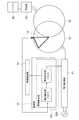
図1は、本発明の一実施形態に係る非接触給電装置を含む車両200及び給電装置100を備えた非接触給電システムのブロック図である。なお、本例の非接触給電装置の車両側のユニットは電気自動車に搭載されるが、ハイブリッド車両等の車両でもよい。<< First Embodiment >>
FIG. 1 is a block diagram of a contactless power feeding system including a
図1に示すように、本例の非接触給電システムは、車両側のユニットを含む車両200と、地上側ユニットである給電装置100とを備え、給電スタンドなどに設置される給電装置100から、非接触で電力を供給し、車両200に設けられるバッテリ28を充電するシステムである。 As shown in FIG. 1, the non-contact power supply system of this example includes a
給電装置100は、電力制御部11と、送電コイル12と、異物検出コイル13と、無線通信部14と、制御部15とを備えている。給電装置100は、車両200を駐車する駐車スペースに設けられており、車両200が所定の駐車位置に駐車されるとコイル間の非接触給電により電力を供給する地上側のユニットである。 The
電力制御部11は、交流電源300から送電される交流電力を、高周波の交流電力に変換し、送電コイル12に送電するための回路であり、整流部111と、PFC(Power Factor Correction)回路112と、インバータ113と、センサ114とを備えている。整流部111は、交流電源300に電気的に接続され、交流電源からの出力交流電力を整流する回路である。PFC回路112は、整流部111からの出力波形を整形することで力率を改善するための回路であり、整流部111とインバータ113との間に接続されている。インバータ113は、平滑コンデンサやIGBT等のスイッチング素子を有したPWM制御回路等を含む電力変換回路であって、制御部15によるスイッチング制御信号に基づいて、直流電力を高周波の交流電力に変換し、送電コイル12に供給する。センサ114は、PFC回路112とインバータ113との間に接続され、電流や電圧を検出する。送電コイル12は、車両200側に設けられている受電コイル22に対して非接触で電力を供給するためのコイルであり、本例の非接触給電装置を設けた駐車スペースに設けられている。 The
車両200が所定の駐車位置に駐車されると、送電コイル12は、受電コイル22の下部であり、受電コイル22と距離を保って、位置づけられる。送電コイル12は、駐車スペースの表面と平行な円形形状のコイルである。 When the
異物検出コイル13は、送電コイル12と受電コイル22との間に存在する異物を検出するためのコイルであり、制御部15により制御される。送電ユニット101は、送電コイル12及び異物検出コイル13を備え、所定の駐車スペースの地上に設けられている。車両200が、本例の非接触給電装置による充電に適した位置である、所定の駐車スペースに駐車されると、送電ユニット101が車両200の後輪の間に位置づけられる。送電ユニット101の具体的な構成は、後述する。 The foreign
無線通信部14は、車両200側に設けられた無線通信部24と、双方向に通信を行い、地上側である給電装置100に設けられている。無線通信部14と無線通信部24との間の通信周波数には、受信部13と送信部23との間の信号の周波数や、インテリジェンスキーなどの車両周辺機器で使用される周波数より高い周波数が設定されているため、無線通信部14と無線通信部24との間で通信を行っても、車両周辺機器は、当該通信による干渉を受けにくい。無線通信部14及び無線通信部24との間の通信には、例えば各種の無線LAN方式が用いられている。 The
制御部15は、給電装置100全体を制御する部分であり、異物検出部151を備え、電力制御部11、送電コイル12、異物検出コイル13及び無線通信部14を制御する。制御部15は、無線通信部14と無線通信部24との間の通信により、給電装置100からの電力供給を開始する旨の制御信号を車両200側に送信したり、車両200側から給電装置100から電力を受給したい旨の制御信号を受信したりする。制御部15は、センサ114の検出電流に基づいて、インバータ113のスイッチング制御を行い、送電コイル12から送電される電力を制御する。 The
車両200は、受電コイル22と、無線通信部24と、充電制御部25と、整流部26と、リレー部27と、バッテリ28と、インバータ29と、モータ30と、通知部32とを備えている。受電コイル22は、車両200の底面(シャシ)等で、後方の車輪の間に設けられている。そして当該車両200が、所定の駐車位置に駐車されると、受電コイル22は、送電コイル12の上部であり、送電コイル12と距離を保って、位置づけられる。受電コイル22は、駐車スペースの表面と平行な円形形状のコイルである。 The
整流部26は、受電コイル22に接続され、受電コイル26で受電された交流電力を直流に整流する整流回路により構成されている。リレー部27は、制御部25の制御によりオン及びオフが切り変わるリレースイッチを備えている。またリレー部27は、当該リレースイッチをオフにすることで、バッテリ28を含む強電系と、充電の回路部となる、受電コイル22及び整流部26の弱電系とを切り離す。 The
バッテリ28は、複数の二次電池を接続することで構成され、車両200の電力源となる。インバータ29は、IGBT等のスイッチング素子を有したPWM制御回路等の制御回路であって、スイッチング制御信号に基づいて、バッテリ28から出力される直流電力を交流電力にし、モータ30に供給する。モータ30は、例えば三相の交流電動機により構成され、車両200を駆動させるための駆動源となる。 The
通知部32は、警告ランプ、ナビゲーションシステムのディスプレイまたはスピーカ等により構成され、充電制御部25による制御に基づいて、ユーザに対して光、画像または音等を出力する。 The
充電制御部25は、バッテリ28の充電を制御するためのコントローラであり、送信部23、無線通信部24、異物検出コイル13及び通知部32を制御し、電力測定部251を備えている。充電制御部25は、充電を開始する旨の信号を、無線通信部24及び無線通信部14の通信により、制御部15に送信する。また充電制御部25は、図示しない、車両200全体を制御するコントローラとCAN通信網で接続されている。当該コントローラは、インバータ28のスイッチング制御や、バッテリ22の充電状態(SOC)を管理する。充電制御部15は、当該コントローラにより、バッテリ22のSOCに基づいて満充電に達した場合に、充電を終了する旨の信号を、制御部15に送信する。 The charging
本例の非接触給電装置では、送電コイル12と受電コイル22との間で、電磁誘導作用により非接触状態で高周波電力の送電及び受電を行う。言い換えると、送電コイル12に電圧が加わると、送電コイル12と受電コイル22との間には磁気的な結合が生じ、送電コイル12から受電コイル22へ電力が供給される。 In the non-contact power feeding device of this example, high-frequency power is transmitted and received between the
次に、図2を用いて、送電コイル12と受電コイル22との間の異物の検出に係る構成を説明する。図2は本例の非接触給電装置の一部である、給電装置100、受電コイル22、整流器26及びバッテリ28のブロック図である。 Next, a configuration related to detection of a foreign object between the
図2に示すように、異物検出コイル13は、複数の異物検出コイル13を有しており、送電コイル12と受電コイル22との間で、送電コイル12の表面上に設けられている。言い換えると、送電コイル12のコイル面、受電コイル22のコイル面、及び異物検出コイル13のコイル面が平行になるよう配置され、異物検出コイル13のコイル面が、送電コイル12のコイル面に含まれるように配置されている。 As shown in FIG. 2, the foreign
異物検出部151は、電圧検出部1511及び異物判定部1512を有している。電圧検出部1511は、異物検出コイル13にそれぞれ接続され、異物検出コイル13a、13bで生じる誘導電圧を検出する。電圧検出部1511は、検出電圧を異物判定部1512に送信する。異物判定部1512は、検出電圧と閾値電圧とを比較することで、送電コイル12と受電コイル22との間に異物が存在するか否かを判定し、判定結果を電力制御部11及び無線通信部14に送信する。異物判定部1512により異物が存在すると判定された場合には、制御部15は、判定結果を含む制御信号により、送電コイル12からの給電を停止するよう、電力制御部11を制御する。送電コイル12と受電コイル22との間に異物が存在する状態で給電を行うと異物を通過する磁束により、異物に渦電流が流れ、異物が発熱する可能性がある。そのため、本例では、異物を検出した場合には、給電を停止するように制御する。 The foreign
また制御部15は、異物を検出した場合には、無線通信部14を介して、異物を検出した旨の信号を車両200側に送信する。充電制御部25は、無線通信部24により受信した当該信号に基づいて、通知部32を制御し、異物が存在することをユーザに通知する。そして、ユーザは、通知部32の通知から、異物が存在することを確認することができる。 In addition, when detecting a foreign object, the
次に、図2及び図3を用いて、本例における、異物を検出する原理を説明する。図3は、異物検出コイル13を通過する磁束により発生する誘導電圧を説明するための図である。 Next, the principle of detecting foreign matter in this example will be described with reference to FIGS. FIG. 3 is a diagram for explaining the induced voltage generated by the magnetic flux passing through the foreign
交流電源300から電力制御部11を介して送電コイル12に電力が供給されると、送電コイル12と受電コイル22との間の磁気的な結合により、電力が送電コイル12から受電コイル22に供給される。給電の際、送電コイル12のコイル面及び受電コイル22のコイル面を通る磁束は、異物検出コイル13のコイル面も通る。異物検出コイル13上に異物40が存在しない場合には、図3(a)に示すように、給電による磁束に応じた誘導電圧がコイル13aの出力電圧として出力される。一方、金属製の異物40が異物検出コイル13上にある場合には、当該異物がコアのように作用するため、図3(b)に示すように、給電による磁束に対して磁束が増加するため誘導電圧が高くなる。 When power is supplied from the
異物判定部1512には、異物40の存在を判定するための判定閾値電圧が設定されており、当該判定閾値電圧は、異物40が存在しない時に異物検出コイル13で発生する誘導電圧、又は、当該誘導電圧より高い電圧が設定されている。なお、判定電圧は、検出対象とする異物40を予め特定した上で、異物が存在する時に発生する誘導電圧は設計段階で予め設定されるため、検出対象となる異物40に応じて設定されればよい。 The foreign
そして、異物判定部1512は、電圧検出部1511により検出された検出電圧が当該判定閾値電圧より高い場合に異物40が存在する、と判定し、電圧検出部1511により検出された検出電圧が当該判定閾値電圧より低い場合に異物40は存在しない、と判定する。 The foreign
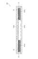
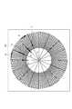
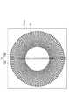
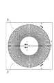
次に、図4〜8を用いて、送電ユニット101の具体的な構成を説明する。図4は送電ユニット101の平面図であり、図5は図4のV-V線に沿う断面図であり、図6は図4のVI-VI線に沿う断面図であり、図7は異物検出コイル13の一部を省略した状態の送電ユニット101の平面図であり、図8は異物検出コイルの一部を省略した状態の送電ユニット101の平面図である。なお、図4、図7及び図8では、保護部材101cの図示を省略している。 Next, a specific configuration of the
送電ユニット101は、送電コイル12と、異物検出コイル13と、フェライトコア101aと、磁気遮蔽板101bと、保護部材101cとを備えている。送電コイル12は、高周波電力を通すように、リッツ線で構成されており、送電コイル12のコイル面が、地面と平行になるように配置されている。車両200が所定の駐車スペースに駐車されると、受電コイル22は送電コイル12と臨む位置に配置され、送電コイル12と受電コイル22とが対向する。言い換えると、送電コイル12の上面が、受電コイル22と対向する送電コイル12の対向面となり、受電コイル22の下面が、送電コイル12と対向する受電コイル22の対向面となる。 The
フェライトコア101aは、直方体状の磁性体の複数の部材により構成され、送電コイル12の下面に配置され、それぞれの磁性体の部材が、送電コイル12の中心点を通る中心軸に対して垂直方向に放射状に配置されている。磁気遮蔽板101bは、地上の表面に沿って設けられ、フェライトコア101aの下面側に設けられ、送電ユニット101の底面となる。磁気遮蔽板101bは、送電コイル12と受電コイル22との間の非接触給電により漏れる磁束を遮蔽し、磁束を外部に漏洩させないようにする部材であり、例えばアルミ板により構成される。 The
保護部材101cは、送電コイル12、フェライトコア101a及び異物検出コイル13を収容するための筐体であり、板状の天板と、当該天板の両端から垂直方向に延在する側壁とにより形成されている。保護部材101cは、ポリプロピレン、ポリアミド等の熱可塑性樹脂で形成されている。 The
異物検出コイル13は、受電コイル22と対向する送電コイル12の対向面側に設けられ、送電コイル12の表面と保護部材101cとの間に設けられている。異物検出コイル13は、複数のコイルにより形成され、複数のコイルは、それぞれ扇形状に形成され、コイル面において、送電コイル12の中心点から放射線状に配置されている。 The foreign
異物検出コイル13は、送電コイル12のコイル面と平行な面に沿って、コイル配線を折り曲げることで形成される。図7に示すように、まず、送電コイル12の中心点と対応する中心点(図7の中心点O)から、送電コイル12の外縁に向けて、コイル配線を引き(図7の矢印a)、送電コイル12の外周部分で当該コイル配線を折り曲げ、送電コイル12の外周の一部に沿って時計回りにコイル配線を引き(図7の矢印b)、中心点Oに向けてコイル配線を折り曲げ、送電コイル12の外縁から中心点Oに向けてコイル配線を引く(図7の矢印c)。これにより、1つ目の扇形状のコイルが形成される。そして、同じコイル配線を用いて、中心点Oから、送電コイル12の外縁に向けて、コイル配線を引き(図7の矢印d)、送電コイル12の外周部分で当該コイル配線を折り曲げ、送電コイル12の外周の一部に沿って時計回りにコイル配線を引き(図7の矢印e)、中心点Oに向けてコイル配線を折り曲げ、送電コイル12の外縁から中心点Oに向けてコイル配線を引く(図7の矢印f)。これにより、2つ目の扇形状のコイルが形成される。1つ目のコイルと二つ目のコイルのコイル面積は等しく、1つ目のコイルと2つ目のコイルとの間には、1つめのコイルと同形状の扇形状のスペースが設けられる。そして、同様に、時計回りの方向で、3つ目のコイルから順にコイルを形成し、送電コイル12の外縁から中心点Oに向けてコイル配線を引いて8つ目のコイルを形成する。これにより、異物検出コイル13の複数のコイルのうち、半分のコイルが形成される。 The foreign
残りの半分のコイルについて、図8に示すように、図7で示すコイルを形成したコイル配線を用いて、中心点Oから、送電コイル12の外縁に向けて、コイル配線を引き(図8の矢印a)、送電コイル12の外周部分で当該コイル配線を折り曲げ、送電コイル12の外周部の一部に沿って反時計回りにコイル配線を引き(図8の屋矢印b)、中心点Oに向けてコイル配線を折り曲げ、送電コイル12の外縁から中心点Oに向けてコイル配線を引く(図8の矢印c)。これにより、1つめの扇形状のコイルが形成される。そして、同じコイル配線を用いて、中心点Oから、送電コイル12の外縁に向けて、コイル配線を引き(図8の矢印d)、送電コイル12の外周部分で当該コイル配線を折り曲げ、送電コイル12の外周の一部に沿って反時計回りにコイル配線を引き(図8の矢印e)、中心点Oに向けてコイル配線を折り曲げ、送電コイル12の外縁から中心点Oに向けてコイル配線を引く(図8の矢印f)。これにより、2つ目の扇形状のコイルが形成される。1つめのコイルと2つ目のコイルのコイル面積は等しく、1つ目のコイルと2つ目のコイルとの間に、図7で示した複数のコイルのうち1つのコイルが配置される。 For the remaining half of the coil, as shown in FIG. 8, using the coil wiring formed with the coil shown in FIG. 7, the coil wiring is drawn from the center point O toward the outer edge of the power transmission coil 12 (FIG. 8). Arrow a), the coil wiring is bent at the outer peripheral portion of the
これにより、異物検出コイル13は、複数のコイルで構成され、当該複数のコイルは一本のコイル配線で繋がり、当該複数のコイルのコイル面積はそれぞれ等面積になる。また、送電コイル12のコイル面は、異物検出コイル13を構成する複数のコイルのコイル面で覆われている。 Thereby, the foreign
異物検出コイル13の一端及び他端は端子(図示しない)に接続され、当該端子を介して、送電ユニット101内の回路基板(図示しない)に接続されている。 One end and the other end of the foreign
次に、図1及び図2を用いて、制御部15及び充電制御部25による制御内容を説明する。 Next, the control content by the
制御部15は、初期化制御として、給電装置100の各システムが正常に動作するか否かを診断するシステムチェックを行う。充電制御部25は、同様に、初期化制御として、車両200の充電システムが正常に動作するか否かを診断するシステムチェックを行う。システムチェックの結果、車両200でシステム異常が生じている場合には、車両200のユーザに通知し、充電装置100でシステム異常が生じている場合には、充電装置100を管理するセンター等に通知する。一方、システムチェックが正常な場合には、制御部15は、無線通信部14を起動させて、信号を受信可能な状態にする。なお、給電装置100側のシステムチェックは、例えば所定の周期で定期的に行い、車両200側のシステムチェックは、例えば車両200を駆動させるためのメインスイッチがオンになった時に行う。 The
制御部15及び充電制御部25は、無線通信部14及び無線通信部24をそれぞれ制御し、以下の遠隔通信制御を行う。まず、充電制御部25は、車両200に設けられているGPS機能より、車両200の現在値の情報を取得し、車両の現在地が、予め設定されている充電ポイント領域内にあるか否かを判断する。ここで、充電ポイント領域とは、各給電装置100に応じて、それぞれ設定される範囲であって、例えば、地図上で、給電装置100の位置を中心とした円状に表示される範囲である。車両200が充電ポイント領域内にあるということは、バッテリ28を充電する際に、当該充電ポイント領域に対応した給電装置100で充電が行われるということを示す。 The
そして、車両200の現在地が充電ポイント領域内にある場合には、充電制御部25は無線通信部24を起動させて、無線通信部14と無線通信部24との間で通信可能な状態にする。無線通信部14と無線通信部24との間で通信可能な状態になると、充電制御部25は、リンクを確立するための信号を、無線通信部24から無線通信部14に送信する。そして、制御部15は、当該信号を受信した旨の信号を、無線通信部14から無線通信部24に送り返す。これにより、無線通信部14と無線通信部24との間でリンクが確立する。 When the current location of the
また、充電制御部25は、無線通信部14と無線通信部24との間の通信で、車両200のIDを、制御部15に送信する。制御部15は、車両200側から送信されたIDが、予め制御部15に登録されているIDと合致するか否かを判定することで、ID認証を行う。本例の非接触給電システムでは、予め給電可能な車両200が給電装置100毎に予めIDにより登録されている。そのため、上記のID認証により、登録IDと合致した車両200が給電することができる。 In addition, the charging
そして、車両200が所定の駐車スペースに駐車されると、受電コイル22が送電コイル12と対向する位置に位置づけられる。ユーザがバッテリ28を充電するための操作を行うと、充電制御部25は、給電を開始する旨の信号を無線通信部24から給電装置100に送信する。制御部15は、無線通信部14により当該信号を受信すると、電力制御部11を制御し、送電コイル12から受電コイル22へ給電を開始する。 When the
制御部15は、バッテリ28を充電するための正規の給電の前に、試し給電を行う。試し給電の送電電力は、正規の給電の送電電力より低い。異物検出部151は、電圧検出部1511により、異物検出コイル13の出力電圧を検出し、異物判定部1512により、検出電圧と判定閾値電圧とを比較し、異物が存在するか否かを判定する。そして、試し給電時に、異物の存在が検出された場合には、制御部15は正規給電を行わず、異物が検出されたことを示す信号を、無線通信部14から車両200に送信する。充電制御部25は、当該信号に基づき、通知部32を制御して、コイル間に異物があることを通知する。これにより、正規の給電前に、異物の存在を検出することができるため、異物からの発熱を抑制することができる。 The
一方、試し給電時に、異物の存在が検出されなかった場合には、制御部15は電力制御部11を制御して正規の給電を行う。充電制御部25は、正規の給電により受電コイル22で受電電力をバッテリ28に供給し、バッテリ28を充電する。 On the other hand, when the presence of a foreign object is not detected during trial power feeding, the
異物検出部151は、正規の給電中も、電圧検出部1511により、異物検出コイル13の出力電圧を検出し、異物判定部1512により、異物の有無を判定する。そして、正規の給電中に、異物が存在すると判定された場合には、制御部15は正規の給電を停止し、異物が存在することを示す信号を車両200側に送信する。充電制御部25は、当該信号に基づき、バッテリ28の充電を停止しつつ、通知部32により、異物が混入されたことを通知する。これにより、正規の給電中も、異物を検出することができ、給電中に異物が混入された場合に、給電を停止し、異物からの発熱を抑えることができる。 The foreign
上記のように、本例は、受電コイル22と対向する送電コイル12の対向面側に異物検出コイル13を設けて、異物検出部151により、異物検出コイル13に生じる誘導電圧に基づき、送電コイル12と受電コイル22との間の異物を検出する。異物が小さい場合には、給電効率の変化量が小さく給電効率からは当該異物を検出することが難しいが、本例では誘導電圧から異物を検出するため、当該異物を検出することができ、また給電効率に基づく異物検出と比較して、検出精度を高めることができる。 As described above, in this example, the foreign
また本例は、異物検出コイル13を複数のコイルで構成する。これにより、当該複数のコイルのそれぞれのコイル面積に対して、異物の占める割合が大きくなるため、磁束変化に対する誘導電圧の変位が大きくなり、異物の検出精度を高めることができる。 In this example, the foreign
また本例において、送電コイル12のコイル面が、異物検出コイル13の複数のコイルで分割されている。これにより、送電コイルのコイル面に相当する領域(異物が存在することで給電を妨げる領域)に対して、異物を検出する単位面積を細分化させることができるため、磁束変化に対する誘導電圧の変位が大きくなり、異物の検出精度を高めることができる。 In this example, the coil surface of the
また本例において、異物検出コイル13は一本のコイル配線で繋がれている。これにより、異物検出コイル13に接続する入出力端子を1つ設ければよい。 In this example, the foreign
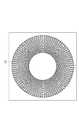
なお本例は、異物検出コイル13を、扇形状の複数のコイルで形成するが、必ずしも扇形状のコイルとする必要はなく、図9に示すように、送電コイル12のコイル面に沿った、円状のコイルとしてもよい。図9は、変形例に係る非接触給電装置の給電ユニット100の平面図である。 In this example, the foreign
また異物検出コイル13は必ずしも送電コイル12のコイル面を覆う必要はなく、少なくとも送電コイル12のコイル面の一部と異物検出コイル13の一部とが重なればよい。また異物検出コイル13は、必ずしも送電コイル12の対向面側に設ける必要はなく、受電コイル22の対向面側に設けてもよく、車両200に設けてもよい。なお異物検出部151を制御部15に設けたが、充電制御部25に設けてもよい。 The foreign
上記送電コイル12または受電コイル22の一方のコイルが本発明に係る第1のコイルに、他方のコイルが本発明に係る第2のコイルに相当し、異物検出コイル13が本発明に係る第3のコイルに相当し、異物検出部151が本発明の異物検出手段に相当する。 One coil of the
《第2実施形態》
発明の他の実施形態に係る非接触給電装置を、図10を用いて説明する。本例は上述した第1実施形態に対して、異物検出コイル13を、複数の独立したコイルで形成する点が異なる。これ以外の構成で上述した第1実施形態と同じ構成は、その記載を適宜、援用する。図10は本例の非接触給電装置に含まれる送電ユニット101の平面図である。なお、図10において、保護部材101cは図示を省略している。<< Second Embodiment >>
A non-contact power feeding device according to another embodiment of the invention will be described with reference to FIG. This example differs from the first embodiment described above in that the foreign
異物検出コイル13は、送電コイル12のコイル面上に、半円状のコイル13aと半円状のコイル13bにより形成されている。コイル13a及びコイル13bは、独立したコイルであり、コイル面積が等しくなるよう構成されている。またコイル13aの両端に接続される入出力端子(図示しない)と、コイル13bの両端に接続される入出力端子(図示しない)は、それぞれ別の端子で構成され、コイル13a及びコイル13bが、それぞれ異物検出部151に接続されている。そのため、電圧検出部1511は、コイル13aの出力電圧と、コイル13bの出力電圧をそれぞれ別々に検出する。 The foreign
異物が異物検出コイル13a上に存在する場合には、非接触給電により、コイル13aの誘導電圧が判定閾値電圧より高くなり、コイル13bの誘導電圧は判定閾値電圧より低くなる。また、異物が異物検出コイル13b上に存在する場合には、コイル13bの誘導電圧が判定閾値電圧より高くなり、コイル13aの誘導電圧は判定閾値電圧より低くなる。 When a foreign object exists on the foreign
異物判定部512は、コイル13a及びコイル13bのそれぞれの出力電圧と判定閾値電圧とをそれぞれ比較し、判定閾値電圧より高い出力電圧を出力するコイル13a、13bのコイル面内に異物が存在する、と判定する。 The foreign matter determination unit 512 compares the respective output voltages of the
本例は、送電コイル12上に、独立したコイル13a、13b、言い換えると、入出力端子がそれぞれ異なるコイル13a、13bを設けることで、送電コイル12のコイル面を複数の領域で分割し、分割された領域に応じた誘起電圧を発生させるため、当該領域を一単位として、異物の場所を特定することができる。 In this example, by providing
なお、本例は、コイル13a、13bを半円状に形成したが、必ずしも半円状にする必要はなく、他の形状であってもよい。 In this example, the
《第3実施形態》
発明の他の実施形態に係る非接触給電装置を、図11〜13を用いて説明する。本例は上述した第1実施形態に対して、異物検出コイル13を、複数の独立したコイルで形成する点が異なる。これ以外の構成で上述した第1実施形態と同じ構成は、その記載を適宜、援用する。図11は本例の非接触給電装置に含まれる送電ユニット101の平面図である。なお、図11において、保護部材101cは図示を省略している。<< Third Embodiment >>
A non-contact power feeding device according to another embodiment of the invention will be described with reference to FIGS. This example differs from the first embodiment described above in that the foreign
異物検出コイル13は、送電コイル12のコイル面と平行な面に沿って、コイル配線を折り曲げることで形成される。図11に示すように、異物検出コイル13は、送電コイル12のコイル面の外縁の一部分(図11の点S)から、中心点Oの左側を通って送電コイル12の直径に沿ってコイル配線を引き(図11の矢印a)、送電コイル12の外周部分で当該配線を折り曲げて、送電コイル12の外周の半円に沿って反時計回りにコイル配線を引き(図11の矢印b)、当該コイル面の外縁の一部分(図11の点S)でコイル配線を折り曲げて、中心点Oの右側を通って送電コイル12の直径に沿ってコイル配線を引き(図11の矢印c)、送電コイル12の外周部分で当該配線を折り曲げて、送電コイル12の外周の半円に沿って時計回りにコイル配線を引き(図11の矢印d)、当該コイル面の外縁の一部分(図11の点S)で、送電コイル12の外周の外側にコイル配線を曲げる、ことで形成されている。 The foreign
すなわち、異物検出コイル13は、一本のコイル配線で、それぞれ同形状で隣接する左側コイル13c及び右側コイル13dにより形成されている。また、左側コイル13cと右側コイル13dは、ねじれの関係になっており、それぞれのコイル面積は等しい。 In other words, the foreign
次に、左側コイル13cに流れる誘導電流及び右側コイル13dに流れる誘電電流と、異物検出コイル13の誘導電圧について、図12及び図13を用いて、説明する。図12は本例の異物検出コイル13の作用を説明するための図であり、図13は時間に対する誘導電圧の特性を示すグラフである。 Next, the induced current flowing through the
左側コイル13cのコイル面及び右側コイル13dのコイル面に異物が存在しない状態で、非接触給電を行うと、図12に示すように、左側コイル13cのコイル面及び右側コイル13dのコイル面を同方向に通る磁束が発生する。そして、左側コイル13c及び右側コイル13dには、磁束に反発するように、誘導電圧が発生する。この時、左側コイル13c及び右側コイル13dは、ねじれの関係になっているため、左側コイル13cを流れる誘導電流は時計回りに流れるが、右側コイル13dを流れる電流は反時計回りに流れる。 When non-contact power feeding is performed in a state where no foreign matter exists on the coil surface of the
また左側コイル13cと右側コイル13dのそれぞれのコイル面積が等しいため、左側コイル13c及び右側コイル13dに流れる、それぞれの誘電電流の向きが互いに逆向きになり、打ち消し合って、電流がゼロになり、異物検出コイル13の出力電圧は図13のグラフ(a)に示すように、ゼロになる。 Also, since the coil areas of the
一方、左側コイル13cのコイル面及び右側コイル13dのコイル面のいずれか一方のコイル面に金属の異物が存在する場合には、異物が存在する方のコイルを通る磁束が強くなるため、異物が存在する方のコイルを流れる誘導電流が、異物が存在しない方のコイルを流れる誘導電流より大きくなる。左側コイル13c及び右側コイル13dの誘電電流は互いに打ち消し合ってゼロにならないため、異物検出コイル13の出力電圧は、図13のグラフ(b)に示すように、ゼロより大きい電圧となる。 On the other hand, when a metal foreign object is present on one of the coil surface of the
上記のように、本例において、異物検出コイル13は、複数のコイル13c、13dで構成され、隣接するコイル13c及びコイル13dは、異物が存在しない場合に、それぞれのコイルを流れる誘導電流の向きが互いに逆向きになるよう配置されている。これにより、左側コイル13c及び右側コイル13dはねじれの関係となり、それぞれのコイルで発生する誘導電流が打ち消し合うため、異物が存在しない場合の誘導電圧に対して、異物が存在する場合の誘導電圧の変化量を検出し易くなり、検出精度を高めることができる。 As described above, in this example, the foreign
また、本例は左側コイル13cのコイル面積と右側コイル13dのコイル面積を等しくする。これにより、異物が存在しない場合に、それぞれのコイルで発生する誘導電流が打ち消し合ってゼロになることで異物検出コイル13の出力電圧がゼロになり、異物が存在する場合には、異物検出コイル13の出力電圧がゼロにならない。ゆえに、異物を検出する際には、誘導電圧をゼロからの変化量を検出すればよいため、検出精度を高めることができる。 In this example, the coil area of the
また本例は、上記の異物検出コイル13における、ねじれの関係を形成するために、図4に示すように、異物検出コイル13を複数の扇形状の、それぞれ独立した一組のコイルで形成し、かつ、送電コイル12の中心点から放射状に配置してもよい。この際、当該一組のコイル間で、ねじれの関係となるように、コイルを形成すル。これにより、異物検出コイル13の複数のコイルは、ねじれの関係となり、異物が存在しない場合には、誘導電圧がゼロになるため、上記と同様に検出精度を高めることができる。 Further, in this example, in order to form a twist relationship in the foreign
なお本例は、ねじれの関係を形成するために、二つのコイルを用いたが、必ずしも二つである必要はなく、複数のコイル間でねじれの関係が形成されるように、異物検出コイル13を構成すればよい。 In this example, two coils are used to form a twist relationship, but the number of coils is not necessarily two, and the foreign
100…給電装置
11…電力制御部
111…整流部
112…PFC回路
113…インバータ
114…センサ
12…送電コイル
13…異物検出コイル
13a、13b…コイル
13c、13d…左側コイル、右側コイル
14…無線通信部
15…制御部
151…異物検出部
1511…電圧検出部
1512…異物判定部
101…送電ユニット
101a…フェライト
101b…磁気遮蔽板
101c…保護部材
200…車両
22…受電コイル
23…送信部
24…無線通信部
25…充電制御部
251…電力測定部
26…整流部
27…リレー部
28…バッテリ
29…インバータ
30…モータ
32…通知部
300…交流電源
40…異物DESCRIPTION OF
Claims (6)
Translated fromJapanese前記第2のコイルの前記第1のコイル側に設けられた第3のコイルと、
前記第3のコイルが前記第1のコイルと前記第2のコイルとの間に位置づけられたとき、前記第1のコイルと前記第2のコイルとの間の磁束の変化による前記第3のコイルに生じる誘導電圧の変化に基づき、前記第1のコイルと前記第2のコイルとの間の異物を検出する異物検出手段とを備え、
前記異物検出手段は、
前記第3のコイルに生じる誘導電圧と、前記異物が存在しないことを示す判定閾値とを比較し、その判定結果に基づき前記異物を検出し、
前記第3のコイルは、
前記第1のコイルと対向する前記第2のコイルの対向面に沿って設けられ、
前記第3のコイルを構成する複数のコイルは、
それぞれ扇形状に形成され、かつ、前記第2のコイルの中心点から放射状に配置されている
ことを特徴とする非接触給電装置。A second coil provided on the ground for transmitting power in a contactless manner with at least a first coil provided on the vehicle by magnetic coupling;
A third coil provided on the first coil side of the second coil;
When the third coil is positioned between the first coil and the second coil, the third coil is caused by a change in magnetic flux between the first coil and the second coil. A foreign matter detection means for detecting a foreign matter between the first coil and the second coil based on a change in induced voltage generated in
The foreign object detection means includes
Comparing the induced voltage generated in the third coil with a determination threshold value indicating that the foreign object does not exist, and detecting the foreign object based on the determination result;
The third coil is
Provided along the facing surface of the second coil facing the first coil;
The plurality of coils constituting the third coil are:
A non-contact power feeding device, wherein each of the non-contact power feeding devicesis formed in a fan shape and is arranged radially from a center point of the second coil .
前記磁性体は、前記第3のコイルと離間させて設けた
ことを特徴とする請求項1記載の非接触給電装置。A magnetic body is provided on the opposite side of the second coil from the first coil side,
The non-contact power feeding apparatus according to claim 1, wherein the magnetic body is provided apart from the third coil.
前記磁性体は、前記第2のコイルと対向する対向面を略平坦にした
ことを特徴とする請求項1又は2記載の非接触給電装置。A magnetic body is provided on the opposite side of the second coil from the first coil side,
The non-contact power feeding apparatus according to claim 1, wherein the magnetic body has a substantially flat facing surface facing the second coil.
ことを特徴とする請求項1〜3のいずれか一項に記載の非接触給電装置。The non-contact power feeding apparatus according to claim 1, wherein the third coil includes a plurality of coils.
前記第3のコイルの前記複数のコイルのうち、隣接する少なくとも二つのコイルは、
前記異物が存在しない場合に、前記二つのコイルを流れる誘導電流の向きが互いに逆向きになるように配置されている
ことを特徴とする請求項4記載の非接触給電装置。The plurality of coils of the third coil are connected by a single wire,
Among the plurality of coils of the third coil, at least two adjacent coils are
The contactless power feeding device according to claim 4, wherein when there is no foreign object, the induction currents flowing through the two coils are arranged in opposite directions.
ことを特徴とする請求項5記載の非接触給電装置。
6. The non-contact power feeding apparatus according to claim 5, wherein the coil areas of the two coils are equal.
Priority Applications (9)
| Application Number | Priority Date | Filing Date | Title |
|---|---|---|---|
| JP2011118663AJP6067211B2 (en) | 2011-05-27 | 2011-05-27 | Non-contact power feeding device |
| EP12793756.3AEP2717431B1 (en) | 2011-05-27 | 2012-05-23 | Contactless electricity supply device |
| BR112013005804-8ABR112013005804B1 (en) | 2011-05-27 | 2012-05-23 | contactless electricity supply device |
| RU2013110059/07ARU2554103C1 (en) | 2011-05-27 | 2012-05-23 | Non-contact power supply device |
| PCT/JP2012/063144WO2012165244A1 (en) | 2011-05-27 | 2012-05-23 | Contactless electricity supply device |
| US13/822,260US9553636B2 (en) | 2011-05-27 | 2012-05-23 | Contactless electricity supply device with foreign object detector |
| CN201280002808.2ACN103098344B (en) | 2011-05-27 | 2012-05-23 | Contactless power supply device |
| MYPI2013000786AMY165789A (en) | 2011-05-27 | 2012-05-23 | Contactless electricity supply device |
| MX2013002741AMX2013002741A (en) | 2011-05-27 | 2012-05-23 | Contactless electricity supply device. |
Applications Claiming Priority (1)
| Application Number | Priority Date | Filing Date | Title |
|---|---|---|---|
| JP2011118663AJP6067211B2 (en) | 2011-05-27 | 2011-05-27 | Non-contact power feeding device |
Related Child Applications (1)
| Application Number | Title | Priority Date | Filing Date |
|---|---|---|---|
| JP2015233145ADivisionJP2016106512A (en) | 2015-11-30 | 2015-11-30 | Non-contact power feeding device |
Publications (2)
| Publication Number | Publication Date |
|---|---|
| JP2012249401A JP2012249401A (en) | 2012-12-13 |
| JP6067211B2true JP6067211B2 (en) | 2017-01-25 |
Family
ID=47259103
Family Applications (1)
| Application Number | Title | Priority Date | Filing Date |
|---|---|---|---|
| JP2011118663AActiveJP6067211B2 (en) | 2011-05-27 | 2011-05-27 | Non-contact power feeding device |
Country Status (9)
| Country | Link |
|---|---|
| US (1) | US9553636B2 (en) |
| EP (1) | EP2717431B1 (en) |
| JP (1) | JP6067211B2 (en) |
| CN (1) | CN103098344B (en) |
| BR (1) | BR112013005804B1 (en) |
| MX (1) | MX2013002741A (en) |
| MY (1) | MY165789A (en) |
| RU (1) | RU2554103C1 (en) |
| WO (1) | WO2012165244A1 (en) |
Families Citing this family (105)
| Publication number | Priority date | Publication date | Assignee | Title |
|---|---|---|---|---|
| EP2754222B1 (en) | 2011-09-09 | 2015-11-18 | Witricity Corporation | Foreign object detection in wireless energy transfer systems |
| JP5967989B2 (en)* | 2012-03-14 | 2016-08-10 | ソニー株式会社 | Detecting device, power receiving device, power transmitting device, and non-contact power feeding system |
| DE102012205283A1 (en) | 2012-03-30 | 2013-10-02 | Bayerische Motoren Werke Aktiengesellschaft | Device for inductive power transmission |
| JP6079026B2 (en)* | 2012-07-26 | 2017-02-15 | Tdk株式会社 | Coil unit and wireless power feeder using the same |
| WO2014038265A1 (en) | 2012-09-05 | 2014-03-13 | ルネサスエレクトロニクス株式会社 | Non-contact charging device, and non-contact power supply system using same |
| GB2508923A (en)* | 2012-12-17 | 2014-06-18 | Bombardier Transp Gmbh | Inductive power transfer system having inductive sensing array |
| JP5780236B2 (en)* | 2012-12-27 | 2015-09-16 | 株式会社デンソー | Metal object detection device |
| JP5910490B2 (en)* | 2012-12-27 | 2016-04-27 | 株式会社デンソー | Metal object detection device |
| WO2014103222A1 (en)* | 2012-12-27 | 2014-07-03 | 株式会社デンソー | Metal object detection device |
| JP6221072B2 (en)* | 2012-12-28 | 2017-11-01 | パナソニックIpマネジメント株式会社 | Contactless power supply |
| WO2014129182A1 (en)* | 2013-02-19 | 2014-08-28 | パナソニック株式会社 | Foreign object detection device, foreign object detection method, and non-contact charging system |
| WO2014129181A1 (en)* | 2013-02-19 | 2014-08-28 | パナソニック株式会社 | Foreign object detection device, foreign object detection method, and non-contact charging system |
| KR20150023837A (en)* | 2013-03-06 | 2015-03-05 | 가부시키가이샤 헤즈 | Contactless power supply device |
| JP2016103865A (en)* | 2013-03-06 | 2016-06-02 | アルプス電気株式会社 | Wireless power transmission system |
| JPWO2014156655A1 (en)* | 2013-03-29 | 2017-02-16 | 日産自動車株式会社 | Non-contact power transmission device |
| JP6036995B2 (en)* | 2013-04-15 | 2016-11-30 | 日産自動車株式会社 | Contactless power supply system |
| JP5857999B2 (en)* | 2013-04-26 | 2016-02-10 | トヨタ自動車株式会社 | Power receiving device, parking assist device, and power transmission system |
| JP2014225961A (en)* | 2013-05-16 | 2014-12-04 | ソニー株式会社 | Detector, power supply system and control method of detector |
| CN104242477A (en)* | 2013-06-24 | 2014-12-24 | 海尔集团技术研发中心 | Wireless electric energy transmission system with impurity detection function and impurity detection method |
| JP2015008608A (en)* | 2013-06-25 | 2015-01-15 | キヤノン株式会社 | Non-contact power transmission / reception system |
| EP3025411B1 (en)* | 2013-07-12 | 2018-09-26 | Schneider Electric USA, Inc. | Method and device for foreign object detection in induction electric charger |
| JP2015023595A (en)* | 2013-07-16 | 2015-02-02 | 株式会社Ihi | Foreign object detection device and method for non-contact power feeding device |
| WO2015008662A1 (en)* | 2013-07-16 | 2015-01-22 | 株式会社Ihi | Foreign matter detection device and method for contactless power supply device |
| JP6172567B2 (en)* | 2013-07-23 | 2017-08-02 | 株式会社Ihi | Foreign object detection device and method for non-contact power feeding device |
| WO2015008462A1 (en)* | 2013-07-18 | 2015-01-22 | パナソニックIpマネジメント株式会社 | Contactless charger, program therefor, and automobile equipped with same |
| EP3046208B1 (en) | 2013-08-21 | 2018-11-28 | Panasonic Intellectual Property Management Co., Ltd. | Portable terminal charging device and automobile equipped with same |
| DE102013219542A1 (en)* | 2013-09-27 | 2015-04-02 | Siemens Aktiengesellschaft | Charging device for inductive wireless delivery of energy |
| US10315523B2 (en)* | 2013-09-27 | 2019-06-11 | Nissan Motor Co., Ltd. | Conductor arrangement structure for wireless power supply system |
| CN103633697A (en)* | 2013-11-22 | 2014-03-12 | 北京航空航天大学 | Electromagnetic inductive type non-contact charging system and aligning method thereof |
| EP3086440B1 (en)* | 2013-12-05 | 2021-02-03 | Panasonic Intellectual Property Management Co., Ltd. | Array coil system |
| JP6248610B2 (en)* | 2013-12-20 | 2017-12-20 | 日産自動車株式会社 | Contactless power supply |
| US9935488B2 (en) | 2013-12-25 | 2018-04-03 | Panasonic Intellectual Property Management Co., Ltd. | Portable terminal charging apparatus and automobile having portable terminal charging apparatus mounted therein |
| JP2015146723A (en)* | 2014-01-06 | 2015-08-13 | 日東電工株式会社 | Wireless power transmitter |
| JP2015159690A (en)* | 2014-02-25 | 2015-09-03 | 株式会社東芝 | Foreign matter detection device, wireless power transmission device, wireless power transmission system |
| CN103904750B (en)* | 2014-04-09 | 2017-02-15 | 凌广 | Automatic charging system of electric automobile |
| DE102014207427A1 (en) | 2014-04-17 | 2015-10-22 | Bombardier Transportation Gmbh | Device and method for detecting a disturbing body in a system for inductive energy transmission and system for inductive energy transmission |
| JP6248785B2 (en)* | 2014-04-25 | 2017-12-20 | トヨタ自動車株式会社 | Power transmission device and power reception device |
| US10295693B2 (en) | 2014-05-15 | 2019-05-21 | Witricity Corporation | Systems, methods, and apparatus for foreign object detection loop based on inductive thermal sensing |
| CN106415977B (en)* | 2014-05-19 | 2019-06-14 | 松下知识产权经营株式会社 | Mobile terminal charging device and vehicle equipped therewith |
| GB2526307A (en)* | 2014-05-20 | 2015-11-25 | Bombardier Transp Gmbh | A housing for at least one object detection device, a primary unit and a pavement slab assembly |
| CN106232248B (en) | 2014-06-30 | 2019-05-10 | 株式会社Ihi | Ground side apparatus, the contactless power supply system of foreign substance removing apparatus, contactless power supply system |
| GB2528474A (en) | 2014-07-23 | 2016-01-27 | Bombardier Transp Gmbh | Operation of an inductive power transfer system |
| US9505315B2 (en) | 2014-08-04 | 2016-11-29 | Qualcomm Incorporated | Wireless charging based on selective activation of transmit antennas |
| CN104906797A (en)* | 2014-08-14 | 2015-09-16 | 王红胜 | Trackless magneto-electricity dynamic vehicle |
| EP3197014B1 (en)* | 2014-08-28 | 2020-01-01 | Panasonic Intellectual Property Management Co., Ltd. | Foreign object detection device |
| JP6417184B2 (en)* | 2014-10-22 | 2018-10-31 | 株式会社テクノバ | Foreign object detector for contactless power supply system |
| CN107112787A (en)* | 2014-11-11 | 2017-08-29 | 鲍尔拜普罗克西有限公司 | Induced power transmitter |
| CN104682488A (en)* | 2014-12-26 | 2015-06-03 | 中兴新能源汽车有限责任公司 | Foreign matter detecting device, foreign matter detecting method and wireless charging system |
| US10302795B2 (en) | 2014-12-30 | 2019-05-28 | Witricity Corporation | Systems, methods, and apparatus for detecting ferromagnetic foreign objects in a predetermined space |
| US10324215B2 (en) | 2014-12-30 | 2019-06-18 | Witricity Corporation | Systems, methods, and apparatus for detecting ferromagnetic foreign objects in a predetermined space |
| EP3979462B1 (en) | 2015-01-19 | 2023-08-16 | IHI Corporation | Power transmission system, foreign object detection device, and coil device |
| US10132650B2 (en)* | 2015-01-22 | 2018-11-20 | Integrated Device Technology, Inc. | Apparatuses and related methods for detecting magnetic flux field characteristics with a wireless power transmitter |
| US10079508B2 (en)* | 2015-01-22 | 2018-09-18 | Integrated Device Technology, Inc. | Apparatuses and related methods for detecting magnetic flux field characteristics with a wireless power receiver |
| JP2016138783A (en)* | 2015-01-27 | 2016-08-04 | トヨタ自動車株式会社 | Metal foreign object detection device |
| WO2016121055A1 (en)* | 2015-01-29 | 2016-08-04 | 日産自動車株式会社 | Power transmission coil structure in contactless power transmission device |
| US9829599B2 (en) | 2015-03-23 | 2017-11-28 | Schneider Electric USA, Inc. | Sensor and method for foreign object detection in induction electric charger |
| US20160380439A1 (en)* | 2015-06-26 | 2016-12-29 | Lei Shao | Notification techniques for wireless power transfer systems |
| DE102015212947A1 (en)* | 2015-07-10 | 2017-01-12 | Siemens Aktiengesellschaft | Device for checking the presence of an electrically conductive body and the charging arrangement including the device |
| JP6458678B2 (en)* | 2015-08-05 | 2019-01-30 | トヨタ自動車株式会社 | Coil unit |
| JP6639204B2 (en) | 2015-11-27 | 2020-02-05 | キヤノン株式会社 | Power transmission equipment |
| US10144301B2 (en) | 2016-02-18 | 2018-12-04 | Denso International America, Inc. | Optimized compensation coils for wireless power transfer system |
| JP6565953B2 (en)* | 2016-03-30 | 2019-08-28 | Tdk株式会社 | Coil unit, wireless power feeding device, wireless power receiving device, and wireless power transmission device |
| US10374467B2 (en) | 2016-03-30 | 2019-08-06 | Tdk Corporation | Coil unit, wireless power feeding device, wireless power receiving device and wireless power transmission device |
| WO2017199361A1 (en)* | 2016-05-18 | 2017-11-23 | 日産自動車株式会社 | Coil unit |
| CN109311404B (en)* | 2016-05-25 | 2019-09-06 | 日产自动车株式会社 | Non-contact power receiving device |
| US10112496B2 (en) | 2016-07-12 | 2018-10-30 | Denso International America, Inc. | Vehicular wireless power transfer system with performance monitoring |
| DE102016219484A1 (en)* | 2016-10-07 | 2018-04-12 | Bayerische Motoren Werke Aktiengesellschaft | Mesh and apparatus for object detection in a magnetic field, method of making the mesh and inductive loading unit |
| US10567042B2 (en)* | 2016-12-01 | 2020-02-18 | Wits Co., Ltd. | Coil module |
| US10401525B2 (en)* | 2017-03-08 | 2019-09-03 | GM Global Technology Operations LLC | Wireless power quality alert for delayed charging with electric vehicles |
| US10128697B1 (en)* | 2017-05-01 | 2018-11-13 | Hevo, Inc. | Detecting and deterring foreign objects and living objects at wireless charging stations |
| DE102017210409A1 (en) | 2017-06-21 | 2018-12-27 | Audi Ag | Component of an inductive energy transfer device with object recognition and method for operating an inductive energy transfer device |
| JP2019009918A (en)* | 2017-06-26 | 2019-01-17 | 株式会社Soken | Power supply device |
| JP6564005B2 (en)* | 2017-12-15 | 2019-08-21 | 株式会社東芝 | Foreign object detection device, wireless power transmission device, and wireless power transmission system |
| CN108177541A (en)* | 2017-12-28 | 2018-06-19 | 上汽通用五菱汽车股份有限公司 | Terrestrial wireless charge control method, device, storage medium and equipment |
| CN108284761A (en)* | 2018-01-17 | 2018-07-17 | 中惠创智无线供电技术有限公司 | A kind of wireless charging vehicle, wireless charging intelligence control system and method |
| EP3528364A1 (en)* | 2018-02-20 | 2019-08-21 | Koninklijke Philips N.V. | Wireless power transfer system |
| KR102077568B1 (en)* | 2018-03-07 | 2020-02-14 | 엘지전자 주식회사 | Foreign Object Detector and wireless charging apparatus |
| EP3553918B1 (en)* | 2018-04-09 | 2020-11-25 | NXP USA, Inc. | A power transmitter unit |
| DE102018213178A1 (en) | 2018-08-07 | 2020-02-13 | Continental Automotive Gmbh | Coil arrangement with a plurality of coil pairs arranged thereon in one plane |
| DE102019200436B4 (en) | 2019-01-16 | 2025-02-06 | Vitesco Technologies GmbH | Coil arrangement with a plurality of coil pairs arranged thereon in a plane and device with such a coil arrangement |
| JP7169897B2 (en)* | 2019-02-12 | 2022-11-11 | 株式会社日立製作所 | Power receiving unit, power transmitting unit and wireless power supply device |
| FR3096190B1 (en) | 2019-05-17 | 2021-04-16 | Continental Automotive | Method of inductive charging control of user equipment and associated charging device for motor vehicle |
| US11605985B2 (en) | 2019-08-20 | 2023-03-14 | Apple Inc. | Wireless power system with object detection |
| JP7268552B2 (en)* | 2019-09-13 | 2023-05-08 | 株式会社Ihi | Coil device |
| EP3836352A1 (en)* | 2019-12-10 | 2021-06-16 | Koninklijke Philips N.V. | Foreign object detection in a wireless power transfer system |
| US11476722B2 (en) | 2020-04-30 | 2022-10-18 | Nucurrent, Inc. | Precision power level control for extended range wireless power transfer |
| US11482890B2 (en) | 2020-04-30 | 2022-10-25 | Nucurrent, Inc. | Surface mountable wireless power transmitter for transmission at extended range |
| US11239709B2 (en) | 2020-04-30 | 2022-02-01 | Nucurrent, Inc. | Operating frequency based power level altering in extended range wireless power transmitters |
| US11310934B2 (en) | 2020-04-30 | 2022-04-19 | Nucurrent, Inc. | Multi-channel cooling for extended distance wireless power transmitter |
| EP3916960A1 (en)* | 2020-05-26 | 2021-12-01 | Koninklijke Philips N.V. | Foreign object detection in a wireless power transfer system |
| DE102020123475A1 (en)* | 2020-09-09 | 2022-03-10 | Audi Aktiengesellschaft | Energy storage device for electrical energy, charging arrangement and method for installing an energy storage device or charging arrangement |
| EP3972085A1 (en)* | 2020-09-18 | 2022-03-23 | EnerSys Delaware Inc. | Wireless induction chargers |
| US11476711B2 (en) | 2020-12-23 | 2022-10-18 | Nucurrent, Inc. | Wireless power transmitters and associated base stations for through-structure charging |
| US11387674B1 (en) | 2020-12-23 | 2022-07-12 | Nucurrent, Inc. | Wireless power transmitters for transmitting power at extended separation distances utilizing concave shielding |
| US11757311B2 (en) | 2020-12-23 | 2023-09-12 | Nucurrent, Inc. | Wireless power transmitters and associated base stations for transmitting power at extended separation distances |
| US11387684B1 (en) | 2020-12-23 | 2022-07-12 | Nucurrent, Inc. | Wireless power transmitters and associated base stations for transmitting power at extended separation distances |
| US11637459B2 (en) | 2020-12-23 | 2023-04-25 | Nucurrent, Inc. | Wireless power transmitters for transmitting power at extended separation distances utilizing T-Core shielding |
| US11791667B2 (en) | 2021-04-30 | 2023-10-17 | Nucurrent, Inc. | Power capability detection for wireless power transmission based on receiver power request |
| US11942799B2 (en) | 2021-04-30 | 2024-03-26 | Nucurrent, Inc. | False notification suppression in wireless power transfer system |
| US11539247B2 (en) | 2021-04-30 | 2022-12-27 | Nucurrent, Inc. | Power capability detection in precision power level control systems for wireless power transmission |
| US11482891B1 (en) | 2021-04-20 | 2022-10-25 | Nucurrent, Inc. | Timing verification in precision power level control systems for wireless power transmission |
| US11532956B2 (en)* | 2021-04-30 | 2022-12-20 | Nucurrent, Inc. | Power capability detection with verification load in power level control systems for wireless power transmission |
| US12132325B2 (en) | 2021-10-12 | 2024-10-29 | Nucurrent, Inc. | Wireless power transmitter with removable magnetic connector panel |
| US11967830B2 (en) | 2021-10-12 | 2024-04-23 | Nucurrent, Inc. | Wireless power transmitters for transmitting power at extended separation distances with magnetic connectors |
| US11637448B1 (en) | 2021-10-12 | 2023-04-25 | Nucurrent, Inc. | Wireless power transmitter with removable magnetic connector panel for vehicular use |
Family Cites Families (37)
| Publication number | Priority date | Publication date | Assignee | Title |
|---|---|---|---|---|
| FR2482362A1 (en)* | 1980-05-12 | 1981-11-13 | Alsthom Atlantique | SHUNT INDUCTANCE ELECTRICAL COIL |
| US5426363A (en)* | 1993-04-26 | 1995-06-20 | Kabushiki Kaisha Honda Denshi Giken | Object detecting device |
| WO1996038898A1 (en) | 1995-05-29 | 1996-12-05 | Matsushita Electric Industrial Co., Ltd. | Power source apparatus |
| JPH10215530A (en)* | 1997-01-28 | 1998-08-11 | Matsushita Electric Works Ltd | Non-contact power transmission device |
| JP3747677B2 (en)* | 1998-03-03 | 2006-02-22 | セイコーエプソン株式会社 | Electronics |
| US6054914A (en) | 1998-07-06 | 2000-04-25 | Midcom, Inc. | Multi-layer transformer having electrical connection in a magnetic core |
| JP3507734B2 (en)* | 1999-10-04 | 2004-03-15 | シャープ株式会社 | Electrical equipment |
| DE10234893A1 (en)* | 2002-07-26 | 2004-02-12 | Sipra Patententwicklungs- Und Beteiligungsgesellschaft Mbh | Device with a stationary and a movable component and a device for the simultaneous transmission of electrical energy and information between these components |
| GB2414121B (en)* | 2004-05-11 | 2008-04-02 | Splashpower Ltd | Controlling inductive power transfer systems |
| JP2006230129A (en)* | 2005-02-18 | 2006-08-31 | Nanao Corp | Noncontact power supply |
| US8169185B2 (en)* | 2006-01-31 | 2012-05-01 | Mojo Mobility, Inc. | System and method for inductive charging of portable devices |
| JP4356844B2 (en) | 2006-10-05 | 2009-11-04 | 昭和飛行機工業株式会社 | Non-contact power feeding device |
| US20100328044A1 (en)* | 2006-10-26 | 2010-12-30 | Koninklijke Philips Electronics N.V. | Inductive power system and method of operation |
| CN101802942A (en)* | 2007-01-29 | 2010-08-11 | 普迈公司 | Pinless power coupling |
| KR102128564B1 (en) | 2007-05-10 | 2020-07-01 | 오클랜드 유니서비시즈 리미티드 | Multi power sourced electric vehicle |
| JP4525710B2 (en) | 2007-06-29 | 2010-08-18 | セイコーエプソン株式会社 | Power transmission control device, power transmission device, electronic device, and non-contact power transmission system |
| DE102007060811A1 (en)* | 2007-09-01 | 2009-03-05 | Maquet Gmbh & Co. Kg | Device and method for wireless energy and / or data transmission between a source device and at least one target device |
| WO2009041058A1 (en)* | 2007-09-27 | 2009-04-02 | Panasonic Corporation | Electronic device, recharger and recharging system |
| US8884468B2 (en)* | 2007-12-21 | 2014-11-11 | Access Business Group International Llc | Circuitry for inductive power transfer |
| KR101061661B1 (en)* | 2008-01-09 | 2011-09-01 | 세이코 엡슨 가부시키가이샤 | Power transmission control device, power transmission device, contactless power transmission system, electronic equipment and power transmission control method |
| US8338990B2 (en)* | 2008-03-13 | 2012-12-25 | Access Business Group International Llc | Inductive power supply system with multiple coil primary |
| US20110074346A1 (en)* | 2009-09-25 | 2011-03-31 | Hall Katherine L | Vehicle charger safety system and method |
| JP5104719B2 (en)* | 2008-10-28 | 2012-12-19 | トヨタ自動車株式会社 | Frequency selection method and quenching depth measurement method in eddy current measurement |
| JP5258521B2 (en) | 2008-11-14 | 2013-08-07 | トヨタ自動車株式会社 | Power supply system |
| JP5521665B2 (en)* | 2009-03-26 | 2014-06-18 | セイコーエプソン株式会社 | Coil unit, power transmission device and power reception device using the same |
| JP5689587B2 (en)* | 2009-03-31 | 2015-03-25 | 富士通株式会社 | Power transmission equipment |
| JP5554937B2 (en)* | 2009-04-22 | 2014-07-23 | パナソニック株式会社 | Contactless power supply system |
| JP5597022B2 (en)* | 2009-05-13 | 2014-10-01 | キヤノン株式会社 | Power supply apparatus and control method |
| DE202009009693U1 (en)* | 2009-07-14 | 2010-11-25 | Conductix-Wampfler Ag | Device for inductive transmission of electrical energy |
| DE102009033236A1 (en) | 2009-07-14 | 2011-01-20 | Conductix-Wampfler Ag | Device for inductive transmission of electrical energy |
| DE102009033237A1 (en) | 2009-07-14 | 2011-01-20 | Conductix-Wampfler Ag | Device for inductive transmission of electrical energy |
| JP5484843B2 (en)* | 2009-09-24 | 2014-05-07 | パナソニック株式会社 | Contactless charging system |
| US8575944B2 (en)* | 2009-11-03 | 2013-11-05 | Robert Bosch Gmbh | Foreign object detection in inductive coupled devices |
| JP2011229264A (en)* | 2010-04-19 | 2011-11-10 | Panasonic Electric Works Co Ltd | Non-contact transmission equipment, non-contact reception equipment and non-contact charging system |
| KR101228556B1 (en)* | 2010-11-04 | 2013-02-07 | 주식회사 한림포스텍 | Method for controlling to select one in plurality of coils in wirelesee power transmission device, wireless power transmission device thereof and wireless power transmission system thereof |
| CN103442634A (en)* | 2011-02-03 | 2013-12-11 | 皇家飞利浦电子股份有限公司 | Planar Coil Arrangement for Magnetic Inductive Impedance Measurement Device |
| US9496081B2 (en)* | 2011-04-08 | 2016-11-15 | Access Business Group International Llc | Counter wound inductive power supply |
- 2011
- 2011-05-27JPJP2011118663Apatent/JP6067211B2/enactiveActive
- 2012
- 2012-05-23MXMX2013002741Apatent/MX2013002741A/enactiveIP Right Grant
- 2012-05-23BRBR112013005804-8Apatent/BR112013005804B1/enactiveIP Right Grant
- 2012-05-23CNCN201280002808.2Apatent/CN103098344B/enactiveActive
- 2012-05-23EPEP12793756.3Apatent/EP2717431B1/enactiveActive
- 2012-05-23MYMYPI2013000786Apatent/MY165789A/enunknown
- 2012-05-23USUS13/822,260patent/US9553636B2/enactiveActive
- 2012-05-23WOPCT/JP2012/063144patent/WO2012165244A1/ennot_activeCeased
- 2012-05-23RURU2013110059/07Apatent/RU2554103C1/enactive
Also Published As
| Publication number | Publication date |
|---|---|
| CN103098344A (en) | 2013-05-08 |
| US9553636B2 (en) | 2017-01-24 |
| WO2012165244A1 (en) | 2012-12-06 |
| MX2013002741A (en) | 2013-05-30 |
| BR112013005804B1 (en) | 2020-12-08 |
| EP2717431B1 (en) | 2018-03-21 |
| EP2717431A4 (en) | 2015-07-15 |
| US20130169062A1 (en) | 2013-07-04 |
| MY165789A (en) | 2018-04-25 |
| JP2012249401A (en) | 2012-12-13 |
| BR112013005804A2 (en) | 2016-05-10 |
| CN103098344B (en) | 2016-05-11 |
| RU2554103C1 (en) | 2015-06-27 |
| EP2717431A1 (en) | 2014-04-09 |
Similar Documents
| Publication | Publication Date | Title |
|---|---|---|
| JP6067211B2 (en) | Non-contact power feeding device | |
| US9722433B2 (en) | Power receiving device, power transmitting device and power transfer system | |
| CN107612157B (en) | Vehicle wireless power transmission system with performance monitoring and monitoring method thereof | |
| JP6427873B2 (en) | Parking assistance device and system | |
| US9409491B2 (en) | Parking assist system for vehicle, contactless power transmitting device, and contactless power receiving device | |
| JP5810632B2 (en) | Non-contact power feeding device | |
| US10279691B2 (en) | Contactless feeding pad and contactless feeding device | |
| US9260026B2 (en) | Vehicle to wireless power transfer coupling coil alignment sensor | |
| US20130335015A1 (en) | Contactless power transmitting device, contactless power receiving device, and contactless power transfer system | |
| EP3269585B1 (en) | Vehicle comprising contactless power reception unit | |
| US10173540B2 (en) | Contactless power transmission device | |
| US20130300354A1 (en) | Vehicle, power receiving device, power transmitting device, and contactless power supply system | |
| JP2016167973A (en) | Interoperable electric vehicle wireless charging method and system | |
| WO2013077326A1 (en) | Non-contact power supply apparatus and non-contact power supply system | |
| JP6566131B2 (en) | Method for detecting coil position of non-contact power feeding system and non-contact power feeding system | |
| WO2013061610A1 (en) | Power supplying apparatus, power receiving apparatus, and non-contact charging apparatus | |
| JP2012023913A (en) | Non-contact power feeding device | |
| WO2013065283A1 (en) | Non-contact charging apparatus | |
| JP2013038893A (en) | Power transmission system | |
| JP6024361B2 (en) | Non-contact power feeding device | |
| JP2011167009A (en) | Noncontact power supply | |
| JP2016106512A (en) | Non-contact power feeding device | |
| JP5930182B2 (en) | antenna | |
| CN104246928B (en) | Contactless power supply device | |
| JP2012239360A (en) | Contactless feed system |
Legal Events
| Date | Code | Title | Description |
|---|---|---|---|
| A621 | Written request for application examination | Free format text:JAPANESE INTERMEDIATE CODE: A621 Effective date:20140318 | |
| A131 | Notification of reasons for refusal | Free format text:JAPANESE INTERMEDIATE CODE: A131 Effective date:20150120 | |
| A521 | Request for written amendment filed | Free format text:JAPANESE INTERMEDIATE CODE: A523 Effective date:20150320 | |
| A02 | Decision of refusal | Free format text:JAPANESE INTERMEDIATE CODE: A02 Effective date:20150901 | |
| A521 | Request for written amendment filed | Free format text:JAPANESE INTERMEDIATE CODE: A523 Effective date:20151130 | |
| A911 | Transfer to examiner for re-examination before appeal (zenchi) | Free format text:JAPANESE INTERMEDIATE CODE: A911 Effective date:20151208 | |
| A912 | Re-examination (zenchi) completed and case transferred to appeal board | Free format text:JAPANESE INTERMEDIATE CODE: A912 Effective date:20160212 | |
| A521 | Request for written amendment filed | Free format text:JAPANESE INTERMEDIATE CODE: A523 Effective date:20161028 | |
| A61 | First payment of annual fees (during grant procedure) | Free format text:JAPANESE INTERMEDIATE CODE: A61 Effective date:20161221 | |
| R150 | Certificate of patent or registration of utility model | Ref document number:6067211 Country of ref document:JP Free format text:JAPANESE INTERMEDIATE CODE: R150 |