JP6061193B2 - Blank stripper mechanism - Google Patents
Blank stripper mechanismDownload PDFInfo
- Publication number
- JP6061193B2 JP6061193B2JP2013055532AJP2013055532AJP6061193B2JP 6061193 B2JP6061193 B2JP 6061193B2JP 2013055532 AJP2013055532 AJP 2013055532AJP 2013055532 AJP2013055532 AJP 2013055532AJP 6061193 B2JP6061193 B2JP 6061193B2
- Authority
- JP
- Japan
- Prior art keywords
- blank
- margin
- width direction
- scraper
- sheet
- Prior art date
- Legal status (The legal status is an assumption and is not a legal conclusion. Google has not performed a legal analysis and makes no representation as to the accuracy of the status listed.)
- Expired - Fee Related
Links
Images


Landscapes
- Details Of Cutting Devices (AREA)
Description
Translated fromJapanese本発明は、例えば紙容器等を作製するためのブランクから余白部を分離するブランクのストリッパ機構に関する。 The present invention relates to a blank stripper mechanism for separating a blank portion from a blank for producing, for example, a paper container or the like.
従来より、例えば紙容器等を作製するため印刷済ブランクが製造される。このようなブランクは後工程において、折罫に沿って折畳まれる。 Conventionally, printed blanks are produced, for example, to produce paper containers and the like. Such blanks are folded along the creases in a later step.
一般に印刷済ブランクは、まずシート状のブランクに印刷が施され、この印刷済のシート状のブランクから複数の製品部と製品部間の余白部と含む枚葉状ブランクが作製される。次にこの枚葉状ブランクのうち余白部がストリッパ機構において製品部から分離されて製品部が得られる。 Generally, a printed blank is first printed on a sheet-like blank, and a sheet-like blank including a plurality of product portions and blank portions between product portions is produced from the printed sheet-like blank. Next, the blank portion of the sheet-like blank is separated from the product portion by the stripper mechanism to obtain the product portion.
ストリッパ機構は、ブランクを搬送するブランク搬送部と、ブランク搬送部により搬送されるブランクの製品部から余白部を分離するため、余白部に差し込まれるピンを有するピンドラムとを備え、ピンドラムのピンを余白部に差し込むことにより、製品部から余白部を分離している。 The stripper mechanism includes a blank conveyance unit that conveys a blank, and a pin drum that has pins inserted into the blank part in order to separate the blank portion from the blank product portion conveyed by the blank conveyance unit. By inserting into the part, the blank part is separated from the product part.
ところで、ブランク搬送部は、複数の送りローラと、送りローラ間に掛け渡されたベルトとを有しているが、このベルトは一般にピンドラムにも巻付けられている。 By the way, the blank conveyance section has a plurality of feed rollers and a belt stretched between the feed rollers, and this belt is generally wound around a pin drum.
このような場合、ピンドラムによりブランクの余白部を製品部から分離する際、余白部がベルトに巻込まれることも考えられる。 In such a case, when the blank portion of the blank is separated from the product portion by the pin drum, the blank portion may be wound around the belt.
本発明はこのような点を考慮してなされたものであり、ブランクの余白部を製品部から分離する際、余白部がブランク搬送部のベルトに巻込まれることを確実に防止することができるブランクのストリッパ機構を提供することを目的とする。 The present invention has been made in consideration of such points, and when the blank portion of the blank is separated from the product portion, the blank portion can reliably prevent the blank portion from being wound around the belt of the blank conveyance portion. An object of the present invention is to provide a stripper mechanism.
本発明は、複数の製品部と、製品部につなぎ部を介して設けられた余白部とを有するブランクを搬送するブランク搬送部と、ブランク搬送部により搬送されるブランクの余白部に差し込まれるピンを外周に有するピンドラムと、ピンドラムとの間でブランクを挟持し、つなぎ部を破断して製品部から余白部を分離するアンビルローラとを備え、ブランク搬送部はブランクの上方に位置する上方ブランク搬送部と、ブランクの下方に位置する下方ブランク搬送部とからなり、下方ブランク搬送部は、複数の下方送りローラと、下方送りローラ間およびピンドラムに掛け渡された複数の下方ベルトとを有し、余白部は、搬送方向部分と幅方向部分とを含む主余白部と、主余白部の幅方向部分に下方ベルト上に位置する分離線を介して連続して設けられ、かつ下方ベルト間に位置する副余白部と、主余白部の搬送方向部分間に独立して設けられた打抜余白部とを有し、ピンドラムの外周に、余白部のうち、主余白部の幅方向部分または副余白部の側縁に当接してこれらを持上げて下方ベルトへの巻込みを防止するとともにピンドラムの外周に対応する内周面を有するスクレーパが配置され、スクレーパは上流側の幅細部と、幅細部から徐々に幅が大きくなって、主余白部の幅方向部分および副余白部側縁と当接してこれを持上げる幅広部を有することを特徴とするブランクのストリッパ機構である。 The present invention relates to a blank transport section that transports a blank having a plurality of product sections and a blank section provided in the product section via a connecting section, and a pin that is inserted into a blank section of the blank transported by the blank transport section A pin drum having an outer periphery and an anvil roller that sandwiches the blank between the pin drum and breaks the connecting portion and separates the blank portion from the product portion, and the blank transport portion is located above the blank. And a lower blank transport unit located below the blank, the lower blank transport unit has a plurality of lower feed rollers, and a plurality of lower belts spanned between the lower feed rollers and the pin drum, The margin portion is continuously provided via a main margin portion including a conveyance direction portion and a width direction portion, and a separation line located on the lower belt in the width direction portion of the main margin portion. And a sub-margin portion located between the lower belts and a punching blank portion provided independently between the conveyance direction portions of the main margin portion, and the main margin of the margin portion is disposed on the outer periphery of the pin drum. A scraper having an inner peripheral surface corresponding to the outer periphery of the pin drum is disposed in contact with the side edge of the width direction portion of the portion or the side margin of the sub-margin portion and lifting them up to prevent the lower belt from being caught. A stripper mechanism for a blank having a wide width portion and a wide portion that gradually increases from the width detail and that abuts against the widthwise portion of the main margin portion and the side margin portion side edge and lifts it up It is.
本発明は、スクレーパはその内周面側に、打抜余白部が入り込むとともに幅広部より幅の狭い薄肉部を有することを特徴とするブランクのストリッパ機構である。 The present invention is a blank stripper mechanism characterized in that the scraper has a thin-walled portion narrower than a wide portion while a blanking blank portion is inserted into an inner peripheral surface side thereof.
本発明は、余白部の副余白部は、下方ベルト間の幅方向中央部に位置することを特徴とするブランクのストリッパ機構である。 The present invention is the blank stripper mechanism characterized in that the sub-margin portion of the margin portion is located in the center portion in the width direction between the lower belts.
本発明は、スクレーパは、下方ベルトと同一の幅方向位置に配置されていることを特徴とするブランクのストリッパ機構である。 The present invention is the blank stripper mechanism in which the scraper is arranged at the same position in the width direction as the lower belt.
本発明は、ブランクの余白部に差し込まれるピンを外周に有するピンドラムの外周に配置されるスクレーパにおいて、余白部は、搬送方向部分と幅方向部分とを含む主余白部と、主余白部の幅方向部分に下ベルト上に位置する分離線を介して連続して設けられ、かつ下方ベルト間に位置する副余白部と、主余白部の搬送方向部分間に独立して設けられた打抜余白部とを有し、スクレーパは上流側の幅細部と、幅細部から徐々に幅が大きくなって、主余白部の幅方向部分または副余白部側縁と当接してこれを持上げる幅広部を有することを特徴とするスクレーパである。 The present invention relates to a scraper disposed on an outer periphery of a pin drum having pins inserted into a blank portion of the blank on the outer periphery, the margin portion including a main margin portion including a conveyance direction portion and a width direction portion, and a width of the main margin portion. Punching blanks provided continuously in the direction portion via a separation line located on the lower belt and independently provided between the sub-margin portion located between the lower belt and the conveyance direction portion of the main margin portion The scraper has an upstream width detail and a wide width part that gradually increases from the width detail and abuts against the width direction part of the main margin part or the side edge of the sub margin part and lifts it up. It is a scraper characterized by having.
以上のように本発明によれば、ブランクの製品部から分離された余白部のうち、主余白部の幅方向部分および副余白部の側縁をスクレーパの幅広部に当接させてこれを持上げることができ、主余白部の幅方向部分および副余白部がブランク搬送部のベルトに巻込まれることを確実に防止することができる。 As described above, according to the present invention, of the blank portion separated from the blank product portion, the width direction portion of the main blank portion and the side edge of the sub blank portion are brought into contact with the wide portion of the scraper and held. Thus, it is possible to reliably prevent the width direction portion of the main margin portion and the sub margin portion from being wound around the belt of the blank conveyance portion.
発明の実施の形態
以下、図面を参照して本発明の実施の形態について説明する。ここで図1乃至図6は本発明の実施の形態を示す図である。DESCRIPTION OF THE PREFERRED EMBODIMENTS Embodiments of the present invention will be described below with reference to the drawings. Here, FIG. 1 to FIG. 6 are diagrams showing an embodiment of the present invention.
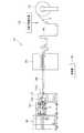
まず、図1により本発明によるブランクのストリッパ機構が組込まれたブランク製造システム全体について説明する。 First, the entire blank manufacturing system in which the blank stripper mechanism according to the present invention is incorporated will be described with reference to FIG.
図1に示すように、ブランク製造システム11は、印刷済の帯状に延びるシート状ブランクSが巻取られ、このシート状ブランクSを巻出す給紙部12と、給紙部12から巻出されたシート状ブランクSの印刷状態の適否を検出する印刷状態検出部13と、シート状ブランクSを搬送するシート搬送部14と、シート状搬送部14により搬送されたシート状ブランクSをプラテンにより打抜いて枚葉状ブランク5(図3参照)を作製する打抜部15とを備えている。なお、給紙部12から枚葉状ブランク5を搬送するようにしてもよいし、プラテンはロータリーダイカッターとしてもよい。 As shown in FIG. 1, the
また打抜部15の下流側に、枚葉状ブランク5を搬送するコンベアを含む枚葉搬送部16が設けられ、枚葉搬送部16の下流側に枚葉状ブランク5から製品部1と、余白部2とを分離する本発明によるストリッパ機構17が設けられている。そしてストリッパ機構17の下流側に、不良品製品部を外部へ排出する不良品製品部排出システム10が配置され、不良品製品部排出システム10により仕分けされた良品製品部は、その後製品部搬送部18により次工程へ搬送される。なお、製品部1の搬送速度は120〜210m/minである。 Further, on the downstream side of the
また、これら給紙部12、印刷状態検出部13、シート搬送部14、打抜部15、枚葉搬送部16、ストリッパ機構17、不良品製品部排出システム10および製品部搬送部18は、いずれも制御部19に接続され、この制御部19によって駆動制御される。 In addition, the
このうち、印刷状態検出部13は、給紙部12から巻出されるシート状ブランクSの印刷状態の適否を検出するものであるが、その他、検出部13によりシート状ブランクSの汚れ、異物等を検出することができる。 Among these, the printing
具体的には印刷状態検出部13はシート状ブランクSのうち製品部1に施された印刷状態、汚れ、異物等を検出し、この検出結果を制御部19へ送るようになっている。 Specifically, the printing
なお、印刷状態検出部13を給紙部12とシート搬送部14との間に設け、この印刷状態検出部13によりシート状ブランクSを検出する場合に限らず、印刷状態検出部13を打抜部15とストリッパ機構17との間に設置し、この印刷状態検出部13により打抜部15により作製された枚葉状ブランク5の印刷状態、汚れ、異物等を検出し、この検出結果を制御部19へ送ってもよい。 The printing
また、打抜部15はシート状ブランクSを打抜いて枚葉状ブランク5を作製するものである。 The
ここで図3および図6により、シート状ブランクSを打抜いてなる枚葉状ブランク5について説明する。 Here, with reference to FIG. 3 and FIG. 6, the single wafer blank 5 formed by punching the sheet blank S will be described.
図3および図6に示すように、枚葉状ブランク5は製品部1と、製品部1間に形成された余白部2とを有している。また各製品部1と余白部2とは、複数のつなぎ部3を介して互いに連結され、つなぎ部3を破断することにより各製品部1と余白部2とを完全に分離することができる。 As shown in FIGS. 3 and 6, the sheet-like blank 5 has a
すなわち、打抜部15において作製された製品部1と余白部2とを有する枚葉状ブランク5は、ストリッパ機構17へ送られ、このストリッパ機構17において、つなぎ部3が破断されて、各製品部1は余白部2から分離される。ここで、つなぎ部3の形状および長さについては、図3および図6に示すものに限られることはなく、その形状および長さは任意に変更することができる。 That is, the sheet-like blank 5 having the
ところでストリッパ機構17において余白部2から分離された各製品部1は、印刷状態が適切な良品製品部と、印刷状態が不適切な不良品製品部とを含むため、不良品製品部は、不良品製品部排出システム10により外部へ排出され、残った良品製品部のみがコンベアからなる製品部搬送部18を介して、次工程へ送られる。 By the way, each
次に本発明によるストリッパ機構17について、図2により説明する。図2に示すようにストリッパ機構17は入口部17aと、出口部17bと、枚葉状ブランク5および製品部1を搬送するブランク搬送部20と、枚葉状ブランク5の余白部2に差し込まれる複数のピン31を外周に有するピンドラム30と、ピンドラム30との間で枚葉状ブランク5を挟持して枚葉状ブランク5を送り出しながらつなぎ部3を破断するアンビルローラ35を有している。またアンビルローラ35の外周には、ピンドラム30のピン31が進入する凹部36が設けられている。 Next, the
さらにまたピンドラム30のピン31は、ピンドラム30の外周に設けられたピン保持部31aにより半径方向に移動自在に保持されている。すなわちピンドラム30内部には、図示しないカム機構が設けられ、このカム機構によりピン31がピンドラム30の上端にきたときピン保持部31aに保持されたピン31がピンドラム30から半径方向外方へ突出するようになっている。そしてピンドラム30の回転によりピン31がピンドラム30の上端から下端へいくに従って、ピン保持部31aに保持されたピン31はピンドラム30内方へ引込み、更にピン31がピンドラム30の下端から上端へいくに従って、再びピン保持部31aに保持されたピン31がピンドラム30から半径方向外方へ突出するようになっている。ピン31が半径方向内方へ引込むことにより、余白部2がピン31から外れる。 Furthermore, the
また、ピンドラム30は駆動モータ33により駆動され、駆動モータ33は制御部19により制御される。なお、ピンドラム30を図示しない駆動ギアを介して他のユニットと連動させて駆動してもよい。 The
ところで、枚葉状ブランク5および製品部1を搬送するブランク搬送部20は、枚葉状ブランク5の上方に位置する上方ブランク搬送部21と、枚葉状ブランク5の下方に位置する下方ブランク搬送部22とを有している。 By the way, the
このうち上方ブランク搬送部21は複数の上方送りローラ21a、21aと、各上方送りローラ21a、21aに掛け渡された上方ベルト21bとを有している。 Among these, the upper
また下方ブランク搬送部22は、入口送りローラ24aと、出口送りローラ24bと、出口送りローラ24bとピンドラム30との間に設けられた一対の下方送りローラ22a、22aとを有している。そして入口送りローラ24aと、出口送りローラ24bと、一対の下方送りローラ22a、22aと、ピンドラム30とに下方ベルト22bが掛け渡されている。 The lower
ピンドラム30を通過するまでは、下方ブランク搬送部22の下方ベルト22bによって、枚葉状ブランク5が搬送される。また、上方ブランク搬送部21の上方ベルト21bと、下方ブランク搬送部22の下方ベルト22bとの間に製品部1が挟持されて製品部1が搬送される。 Until passing through the
このように下方ブランク搬送部22により枚葉状ブランク5を搬送させながら、ピンドラム30とアンビルローラ35とにより枚葉状ブランク5の製品部1から余白部2を分離するようになっている。 In this way, the
また、ピンドラム30の外周に、余白部2の側縁に当接して、この余白部2の側縁を持上げるスクレーパ25が配置されている。そしてスクレーパ25により余白部2のうち、後述する主余白部2aの幅方向分部2Bと副余白部2bの側縁を持上げることにより、余白部2の幅方向部分2Bと副余白部2bが下方ブランク搬送部22のピンドラム30側の下方送りローラ22aを通過後の下方ベルト22bとピンドラム30との間に巻込まれることを防止することができる。 Further, a
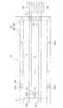
次に枚葉状ブランク5の余白部2と、下方ベルト22bとの位置関係について図3および図6を用いて説明する。なお、図3および図6は、ピンドラム30を通過する手前の枚葉状ブランク5と下方ベルト22との位置関係を平面視したものである。わかりやすくするために、上方ブランク搬送部21、下方ベルト22b以外の下方ブランク搬送部22、ピンドラム30、アンビルローラ35を省略して図示しており、便宜上枚葉状ブランク5を透明体として示している。 Next, the positional relationship between the
図3および図6に示すように、枚葉状ブランク5は、搬送方向(矢印L方向)に沿って形成された搬送方向部分2Aを含む複数の主余白部2aによって、幅方向に8つの領域に区画され、さらに幅方向に延びる分離線4によって各領域が搬送方向に沿って上流側と下流側に区画されて、合計16の製品部1を有する。 As shown in FIG. 3 and FIG. 6, the sheet-like blank 5 is divided into eight regions in the width direction by a plurality of
また幅方向および搬送方向に区画された各製品部1に対して一対の下方ベルト22bが配置され、このため一つの枚葉状ブランク5に対して合計16本の下方ベルト22bが設けられている。なお、下方ベルト22bは枚葉状ブランク5の下方に位置するものである。 In addition, a pair of
また主余白部2aは搬送方向部分2Aに連結された幅方向部分2Bを含むとともに、主余白部2aの幅方向部分2Bに分離線6を介して副余白部2bが搬送方向と直交して(幅方向に)形成されている。すなわち主余白部2aの幅方向部分2Bと、副余白部2bは分離線6を介して互いに分離している。 The
さらにまた枚葉状ブランク5の各製品部1には、その幅方向の中央部に打抜余白部2cがつなぎ部3を介して形成されている。また枚葉状ブランク5の副余白部2bも各製品部1の幅方向の中央部に形成されており、各製品部1毎に設けられた一対の下方ベルト22b、22bは製品部1の幅方向中心線lに対して左右対象に配置されている。 Further, each
このため、各製品部1において、副余白部2bおよび打抜余白部2cは、いずれも製品部1の幅方向中心線l上にあり、かつ副余白部2bおよび打抜余白部2cは一対の下方ベルト22b、22bの間の幅方向中央部に位置している。 For this reason, in each
ここで打抜余白部2cは、例えば、包装容器内に収容された内容物を視認するための窓部を形成するために設けられる。但し、打抜余白部2cは窓部に限定されるものではない。 Here, the blanking
上記のうち、枚葉状ブランク5の搬送方向部分2Aおよび幅方向部分2Bを含む主余白部2a、幅方向に延びる副余白部2bおよび打抜余白部2cによって余白部2が構成される。 Among the above, the main
なお、図3に示すように主余白部2aの搬送方向部分2Aの中央に分離線2Dが形成され、この分離線2Dにより搬送方向部分2Aは上流側と下流側とに分離されている。 As shown in FIG. 3, a
また図3において、搬送方向部分2Aと幅方向部分2Bを含む主余白部2a、副余白部2b、および打抜余白部2cの各々に、ピンドラム31が挿入されるピン位置31dが示されている。 In FIG. 3, pin positions 31d into which the pin drums 31 are inserted are shown in the
またピンドラム30の外周に、ピンドラム30とアンビルローラ35とにより枚葉状ブランク5の製品部1から分離された余白部2のうち主余白部2aの幅方向部分2Bおよび副余白部2bを持上げてピンドラム30側の下方送りローラ22aを通過後の下方ベルト22bとピンドラム30との間への巻込みを防止するスクレーパ25が設けられている。 Further, the
ここで、スクレーパ25は、枚葉状ブランク5に対して16本設置された下方ベルト22bのうち、各々の下方ベルト22bと同一の幅方向位置に設けられている。 Here, the
このため、枚葉状ブランク5に対して16本設けられた下方ベルト22に対し、同数の16個のスクレーパ25が設けられている。 For this reason, the same number of 16
各スクレーパ25は、図4(a)(b)に示すように、正面からみて上流側の幅細部27と、幅細部27から徐々に幅が広くなる幅広部26とを有している。枚葉状ブランク5の主余白部2aの幅方向部分2Bおよび副余白部2bは、各側縁が最初にスクレーパ25の幅細部27に当接し、その後幅細部27から幅広部26に移行しながら徐々に持上げられ、このことにより主余白部2aの幅方向部分2Bおよび副余白部2bがピンドラム30側の下方送りローラ22aを通過後の下方ベルト22bとピンドラム30との間に巻込まれることを防止できる。 As shown in FIGS. 4A and 4B, each
また各スクレーパ25は、図4(a)(b)に示すように、円弧形状の内周面25aを有しており、この内周面25aはピンドラム30に当接あるいは近接するように設けられている。ここで、近接とはスクレーパ25とピンドラム30との間の間隔が製品部1の厚み未満である状態をいう。また各スクレーパ25はピンドラム30の中心から枚葉ブンラク5の搬送方向の下流側であって、ピンドラム30の下方ベルト22bと接しない領域を覆うように設けられている。 Each
さらにまた、各スクレーパ25の細幅部27は枚葉ブランク5の搬送方向の上流側に位置し、幅広部26は下流側に位置している。 Furthermore, the
この場合、主余白部2aの幅方向部分2Bおよび副余白部2bの側縁は、互いの分離線6に対応しており、主余白部2aの幅方向部分2Bおよび副余白部2bの分離線6により形成された側縁をスクレーパ25の幅細部27および幅広部26により持上げることができる。 In this case, the side edges of the
次にスクレーパ25の材料について述べる。スクレーパ25は円弧形状の内周面をもち、例えば、板状体に旋盤やスライス加工などの切削加工を施すことにより作製することができる。 Next, the material of the
スクレーパ25は余白部2が接触しても変形しないように、枚葉状ブランク5より剛性が高いことが好ましい。また、スクレーパ25はピンドラム30と当接するように配置したときに、ピンドラム30の回転を妨げにくくするために、ピンドラム30より剛性が低いことが好ましい。 It is preferable that the
スクレーパ25の材質としては、エンジニアリングプラスチックが好ましい。エンジニアリングプラスチックとしては、POM(ポリオキシメチレン)、PA(ポリアミド)、PC(ポリカーボネート)、PBT(ポリブチレンテレフタレート)などが挙げられる。 As a material of the
スクレーパ25をピンドラム30と接触するように配置する場合、ピンドラム30の外径よりもスクレーパ25の内周面25aの円弧の径を小さくなるように形成することが好ましい。この場合は、使用によりピンドラム30によってスクレーパ25が削られ、ピンドラム30の外径とスクレーパ25の内周面25aの円弧の径が略同一となるため、本発明の効果を向上させることができる。 When the
またスクレーパ25の幅広部26の厚みは、例えば、11〜18mm、薄肉部を8mmとすることができる。 Moreover, the thickness of the
次にこのような構成からなる本実施の形態の作用について説明する。 Next, the operation of the present embodiment having such a configuration will be described.
まず図1に示すように、印刷済のシート状ブランクSが給紙部12に巻き取られ、給紙部12からシート状ブランクSが巻出される。 First, as shown in FIG. 1, the printed sheet-like blank S is wound around the
次に印刷状態検出部13において、給紙部12から巻出されたシート状ブランクSの印刷状態の適否が検出され、シート状ブランクSはシート搬送部14により搬送される。 Next, in the printing
このように印刷状態検出部13は、給紙部12から巻出されるシート状ブランクSの印刷状態の適否を検出する。この場合、印刷状態検出部13によりシート状ブランクSの印刷状態だけではなく、シート状ブランクSの汚れ、異物等を検出してもよい。 As described above, the printing
具体的には印刷状態検出部13はシート状ブランクSのうち製品部となるブランク1に施された印刷状態、汚れ、異物等を検出し、この検出結果を制御部19へ送る。 Specifically, the printing
次にシート搬送部14により搬送されたシート状ブランクSは打抜部15に送られる。 Next, the sheet-like blank S conveyed by the
その後、打抜部15において、シート状ブランクSが打抜かれて、枚葉状ブランク5が得られる。 Then, in the punching
図3に示すように、枚葉状ブランク5は、幅方向に8つに区画され、搬送方向に沿って上流側と下流側の2つに区画された合計16個の製品部1と、製品部1間に形成された主余白部2aおよび副余白部2bとを有している。また各製品部1と主余白部2aおよび副余白部2bはつなぎ部3を介して連結され、主余白部2aの幅方向部分2Bと副余白部2bは分離線6を介して互いに分離している。 As shown in FIG. 3, the sheet-like blank 5 is divided into eight in the width direction, and a total of sixteen
また各製品部1内にはつなぎ部3を介して打抜余白部2cが形成されている。この場合、搬送方向部分2Aと幅方向部分2Bを含む主余白部2aと、副余白部2bと、打抜余白部2cとにより余白部2が形成される。 Further, a punching
打抜部15において作製された製品部1と余白部2とを有する枚葉状ブランク5は、ストリッパ機構17へ送られる。そしてこのストリッパ機構17において、つなぎ部3が破断されて、各製品部1は余白部2から分離され、このようにして製品部1が得られる。 The sheet-like blank 5 having the
次にストリッパ機構17における作用について、図2乃至図5により以下説明する。 Next, the operation of the
まず枚葉状ブランク5が枚葉搬送部16から入口部17aを経て、ストリッパ機構17内に入り、ブランク搬送部20の下方ブランク搬送部22により、ピンドラム30とアンビルローラ35との間に搬送速度120〜210m/minで搬送され、この間、枚葉状ブランク5はピンドラム30とアンビルローラ35との間で挟持される。 First, the sheet-like blank 5 enters the
この場合、ピンドラム30の外周に設けられたピン31が枚葉状ブランク5の余白部2に差し込まれ、ピンドラム30のピン31はアンビルローラ35の凹部36内に進入する。 In this case, the
この際、枚葉状ブランク5のつなぎ部3が破断されて枚葉状ブランク5の製品部1から余白部2が分離され、製品部1がピンドラム30とアンビルローラ35との間から、ブランク搬送部20によって下流側へ送り出される。そして、製品部1は出口部17bを経て不良品ブランク排出システム10側へ送られ、余白部2はピンドラム30の回転に伴なってピンドラム30の下方へ送られる。 At this time, the connecting
この間、ピンドラム30の回転に伴なってピン31が半径方向内方へ引込み、このことにより余白部2からピン31が引き抜かれ、余白部2はその後ピンドラム31から余白部集積装置40内へ落下して余白部集積装置40内で集積される。 During this time, as the
また、余白部2のうち主余白部2aの幅方向部分2Bと副余白部2bは、各スクレーパ25により持ち上げられて下方ベルト22bとピンドラム30との間に巻込まれることが防止される。 Further, the
次に主余白部2aの幅方向部分2Bと副余白部2bの側縁6をスクレーパ25により持ち上げる作用について図5により説明する。 Next, the action of lifting the
ここで、図5はスクレーパ25により、主余白部2aの幅方向部分2Bが持上げられた状態を示しており、副余白部2bについては便宜上図示は省略する。また図5において主余白部2aに、ピン31の貫通孔31cが示されている。 Here, FIG. 5 shows a state in which the
図5に示すように、主余白部2aの幅方向部分2Bと副余白部2bの側縁(分離線)6がまず各スクレーパ25の幅細部27に当接し、主余白部2aの幅方向部分2Bと副余白部2bの側縁6が幅細部27から幅広部26へ移行して、徐々に持上げられる。また上述のように各スクレーパ25は、下方ブランク搬送部22の下方ベルト22bと同一の幅方向位置に設けられている。 As shown in FIG. 5, the
このためスクレーパ25の幅細部27および幅広部26に当接して、その側縁6が持ち上げられた主余白部2aの幅方向部分2Bと副余白部2bはピンドラム30側の下方送りローラ22aを通過後の下方ベルト22bとピンドラム30との間に巻込まれることはない。 Therefore, the
このようにして、ストリッパ機構17において余白部2から分離された製品部1が得られる。ストリッパ機構17において得られた製品部1は、印刷状態が適切な良品製品部と、印刷状態が不適切な不良品製品部とを含むため、不良品製品部を不良品製品部排出システム10により外部へ排出する必要がある。 In this way, the
すなわち、ストリッパ機構17の出口部17bから製品部1が不良品製品部排出システム10内へ送られる。 That is, the
この場合、印刷状態検出部13からの信号が制御部19に入力され、制御部19は印刷状態検出部13からの信号に基づいて各製品部1を良品製品部と不良品製品部とに区別しこれらを特定する。 In this case, a signal from the printing
次に制御部19は、不良品製品部排出システム10において、良品製品部から不良品製品部を分離する。 Next, the
このようにして、良品製品部から不良品製品部を分離して、良品製品部のみを製品部搬送部18から次工程へ送る。 In this way, the defective product part is separated from the non-defective product part, and only the good product part is sent from the product
以上説明したように、本実施の形態によれば、枚葉状ブランク5の余白部2を製品部1から分離する際、余白部2の主余白部2aの幅方向部分2Bと副余白部2bの側縁をスクレーパ25の幅広部26により持上げることができる。このため余白部2が下方ブランク搬送部22のピンドラム30側の下方送りローラ22aを通過後の下方ベルト22bとピンドラム30との間に巻込まれることはない。 As described above, according to the present embodiment, when the
変形例
次に図7によりスクレーパ25の変形例について説明する。図1乃至図6に示す実施の形態において、スクレーパ25が上流側の幅細部27と、幅細部27から徐々に幅が大きくなる幅広部26とを有する例を示したが、図7(a)(b)に示すようにスクレーパ25は上流側の幅細部27と、幅細部27から徐々に幅が大きくなる幅広部26と、幅広部26の内周面側に位置する薄肉部28とを有していてもよい。Themodification then 7 describes a variation of the
すなわち、スクレーパ25は円弧形状の内周面25aを有している。また、スクレーパ25のうち、幅広部26の内周面側25aに余白部2の打抜余白部2cが入り込むとともに、幅広部26よりも幅の狭い薄肉部28が形成されている。上述のように枚葉状ブランク5には余白部2が形成され、この余白部2の打抜余白部2cもピンドラム30およびアンビルローラ31により製品部1から分離される。この場合、打抜余白部2cの形状がスクレーパ25に達する程度に大きい場合、この打抜余白部2cをスクレーパ25の内周面側に形成された薄肉部28内に収めることにより、打抜余白部2cが外方へ飛び出したり、下流側の下方ベルト22bに巻込まれることはない(図7参照)。 That is, the
次に図8により、ブランクの変形例について説明する。図1乃至図6に示す実施の形態において、枚葉状ブランク5に余白部2を形成するとともに、余白部2が搬送方向部分2Aと搬送方向部分2Aに連結された幅方向部分2Bとを有する主余白部2aを有する例を示したが、搬送方向部分2Aと幅方向部分2Bとは必ずも連結されていなくてもよい。 Next, a modified example of the blank will be described with reference to FIG. In the embodiment shown in FIG. 1 to FIG. 6, the
すなわち、図3におよび図6に示す実施の形態において、搬送方法部2Aと幅方向2Bは互いに連結されてL字形状を構成しているが、図8に示すように、搬送方向部分2Aと幅方向部分2Bを分離線2Eを介して互いに分離させてもよい。 That is, in the embodiment shown in FIG. 3 and FIG. 6, the
また上記各実施の形態において、ストリッパ機構17において、枚葉状ブランク5の製品部1から余白部2を分離した例を示したが、枚葉状ブランク5の代わりに連続シート状のブランクを用い、ストリッパ機構17により連続シート状のブランクについて、製品部と余白部とを分離してもよい。 Moreover, in each said embodiment, although the
さらにまた上記各実施の形態において、各製品部1に対応して一対の下方ベルト22bを配置した例を示したが、これに限らず一対の下方ベルト22bのうち一方の下方ベルト22bを搬送ガイドに置き換えてもよい。なお、搬送ガイドとは、ガイドレールのことを指し、製品部1を下側から支えるように、ピンドラム30と出口送りローラ24bの間に設けられる。 Furthermore, in each of the above-described embodiments, an example in which a pair of
1 製品部
2 余白部
2a 主余白部
2A 搬送方向部分
2B 幅方向部分
2b 副余白部
2c 打抜余白部
2D 分離線
2E 分離線
3 つなぎ部
4 分離線
5 枚葉状ブランク
6 分離線
10 不良品製品部排出システム
12 給紙部
13 印刷状態検出部
14 シート搬送部
15 打抜部
16 枚葉搬送部
17 ストリッパ機構
18 製品部搬送部
19 制御部
20 ブランク搬送部
21 上方ブランク搬送部
21a 上方送りローラ
21b 上方ベルト
22 下方ブランク搬送部
22a 下方送りローラ
22b 下方ベルト
24a 入口送りローラ
24b 出口送りローラ
25 スクレーパ
26 幅広部
27 幅細部
28 薄肉部
30 ピンドラム
31 ピン
31a ピン保持部
31d ピン挿入位置
33 駆動モータ
35 アンビルローラ
36 凹部DESCRIPTION OF
Claims (5)
Translated fromJapaneseブランク搬送部により搬送されるブランクの余白部に差し込まれるピンを外周に有するピンドラムと、
ピンドラムとの間でブランクを挟持し、つなぎ部を破断して製品部から余白部を分離するアンビルローラとを備え、
ブランク搬送部はブランクの上方に位置する上方ブランク搬送部と、ブランクの下方に位置する下方ブランク搬送部とからなり、
下方ブランク搬送部は、複数の下方送りローラと、下方送りローラ間およびピンドラムに掛け渡された複数の下方ベルトとを有し、
余白部は、搬送方向部分と幅方向部分とを含む主余白部と、主余白部の幅方向部分に下方ベルト上に位置する分離線を介して連続して設けられ、かつ下方ベルト間に位置する副余白部と、主余白部の搬送方向部分間に独立して設けられた打抜余白部とを有し、
ピンドラムの外周に、余白部のうち、主余白部の幅方向部分または副余白部の側縁に当接してこれらを持上げて下方ベルトへの巻込みを防止するとともにピンドラムの外周に対応する内周面を有するスクレーパが配置され、
スクレーパは上流側の幅細部と、幅細部から徐々に幅が大きくなって、主余白部の幅方向部分および副余白部側縁と当接してこれを持上げる幅広部を有することを特徴とするブランクのストリッパ機構。A blank transport section for transporting a blank having a plurality of product sections and a blank section provided on the product section via a connecting section;
A pin drum having a pin inserted into a blank margin of the blank transported by the blank transport unit on the outer periphery;
An anvil roller that holds the blank between the pin drum and breaks the connecting portion to separate the blank portion from the product portion,
The blank transport unit is composed of an upper blank transport unit positioned above the blank and a lower blank transport unit positioned below the blank.
The lower blank conveyance unit has a plurality of lower feed rollers, and a plurality of lower belts spanned between the lower feed rollers and the pin drum,
The margin portion is provided continuously with a main margin portion including a conveyance direction portion and a width direction portion, and a width direction portion of the main margin portion via a separation line located on the lower belt, and is positioned between the lower belts. A sub-margin portion, and a blanking portion provided independently between conveyance direction portions of the main margin portion,
An inner circumference corresponding to the outer circumference of the pin drum while preventing the winding of the lower belt by abutting against the width direction portion of the main margin portion or the side margin of the sub margin portion of the margin portion and lifting them up on the outer circumference of the pin drum A scraper having a surface is arranged,
The scraper has an upstream width detail, and a wide portion that gradually increases in width from the width detail, and has a wide portion that abuts and lifts the width direction portion of the main blank portion and the side margin portion side edge. Blank stripper mechanism.
余白部は、搬送方向部分と幅方向部分とを含む主余白部と、主余白部の幅方向部分に下ベルト上に位置する分離線を介して連続して設けられ、かつ下方ベルト間に位置する副余白部と、主余白部の搬送方向部分間に独立して設けられた打抜余白部とを有し、
スクレーパは上流側の幅細部と、幅細部から徐々に幅が大きくなって、主余白部の幅方向部分または副余白部側縁と当接してこれを持上げる幅広部を有することを特徴とするスクレーパ。In a scraper disposed on the outer periphery of a pin drum having an outer periphery with a pin inserted into a blank margin,
The margin portion is provided continuously with a main margin portion including a conveyance direction portion and a width direction portion, and a width direction portion of the main margin portion via a separation line located on the lower belt, and is positioned between the lower belts. A sub-margin portion, and a blanking portion provided independently between conveyance direction portions of the main margin portion,
The scraper is characterized by having an upstream width detail, and a wide portion that gradually increases from the width detail, and that abuts against and raises the width direction portion of the main margin portion or the side margin portion side edge. Scraper.
Priority Applications (1)
| Application Number | Priority Date | Filing Date | Title |
|---|---|---|---|
| JP2013055532AJP6061193B2 (en) | 2013-03-18 | 2013-03-18 | Blank stripper mechanism |
Applications Claiming Priority (1)
| Application Number | Priority Date | Filing Date | Title |
|---|---|---|---|
| JP2013055532AJP6061193B2 (en) | 2013-03-18 | 2013-03-18 | Blank stripper mechanism |
Publications (2)
| Publication Number | Publication Date |
|---|---|
| JP2014180710A JP2014180710A (en) | 2014-09-29 |
| JP6061193B2true JP6061193B2 (en) | 2017-01-18 |
Family
ID=51699906
Family Applications (1)
| Application Number | Title | Priority Date | Filing Date |
|---|---|---|---|
| JP2013055532AExpired - Fee RelatedJP6061193B2 (en) | 2013-03-18 | 2013-03-18 | Blank stripper mechanism |
Country Status (1)
| Country | Link |
|---|---|
| JP (1) | JP6061193B2 (en) |
Cited By (9)
| Publication number | Priority date | Publication date | Assignee | Title |
|---|---|---|---|---|
| US11130701B2 (en) | 2016-09-30 | 2021-09-28 | Corning Incorporated | Apparatuses and methods for laser processing transparent workpieces using non-axisymmetric beam spots |
| US11148225B2 (en) | 2013-12-17 | 2021-10-19 | Corning Incorporated | Method for rapid laser drilling of holes in glass and products made therefrom |
| US11345625B2 (en) | 2013-01-15 | 2022-05-31 | Corning Laser Technologies GmbH | Method and device for the laser-based machining of sheet-like substrates |
| US11542190B2 (en) | 2016-10-24 | 2023-01-03 | Corning Incorporated | Substrate processing station for laser-based machining of sheet-like glass substrates |
| US11556039B2 (en) | 2013-12-17 | 2023-01-17 | Corning Incorporated | Electrochromic coated glass articles and methods for laser processing the same |
| US11648623B2 (en) | 2014-07-14 | 2023-05-16 | Corning Incorporated | Systems and methods for processing transparent materials using adjustable laser beam focal lines |
| US11697178B2 (en) | 2014-07-08 | 2023-07-11 | Corning Incorporated | Methods and apparatuses for laser processing materials |
| US11713271B2 (en) | 2013-03-21 | 2023-08-01 | Corning Laser Technologies GmbH | Device and method for cutting out contours from planar substrates by means of laser |
| US11773004B2 (en) | 2015-03-24 | 2023-10-03 | Corning Incorporated | Laser cutting and processing of display glass compositions |
Family Cites Families (3)
| Publication number | Priority date | Publication date | Assignee | Title |
|---|---|---|---|---|
| JPS54121890A (en)* | 1978-03-14 | 1979-09-21 | United Patents Trust Reg | Method and machine for separating previously punched sheet |
| JPS6150797A (en)* | 1984-08-01 | 1986-03-13 | レンゴ−株式会社 | Treater for sheet punching chip |
| US8272923B2 (en)* | 2009-08-13 | 2012-09-25 | The Procter & Gamble Company | Methods and apparatuses for anvil reconditioning |
- 2013
- 2013-03-18JPJP2013055532Apatent/JP6061193B2/ennot_activeExpired - Fee Related
Cited By (9)
| Publication number | Priority date | Publication date | Assignee | Title |
|---|---|---|---|---|
| US11345625B2 (en) | 2013-01-15 | 2022-05-31 | Corning Laser Technologies GmbH | Method and device for the laser-based machining of sheet-like substrates |
| US11713271B2 (en) | 2013-03-21 | 2023-08-01 | Corning Laser Technologies GmbH | Device and method for cutting out contours from planar substrates by means of laser |
| US11148225B2 (en) | 2013-12-17 | 2021-10-19 | Corning Incorporated | Method for rapid laser drilling of holes in glass and products made therefrom |
| US11556039B2 (en) | 2013-12-17 | 2023-01-17 | Corning Incorporated | Electrochromic coated glass articles and methods for laser processing the same |
| US11697178B2 (en) | 2014-07-08 | 2023-07-11 | Corning Incorporated | Methods and apparatuses for laser processing materials |
| US11648623B2 (en) | 2014-07-14 | 2023-05-16 | Corning Incorporated | Systems and methods for processing transparent materials using adjustable laser beam focal lines |
| US11773004B2 (en) | 2015-03-24 | 2023-10-03 | Corning Incorporated | Laser cutting and processing of display glass compositions |
| US11130701B2 (en) | 2016-09-30 | 2021-09-28 | Corning Incorporated | Apparatuses and methods for laser processing transparent workpieces using non-axisymmetric beam spots |
| US11542190B2 (en) | 2016-10-24 | 2023-01-03 | Corning Incorporated | Substrate processing station for laser-based machining of sheet-like glass substrates |
Also Published As
| Publication number | Publication date |
|---|---|
| JP2014180710A (en) | 2014-09-29 |
Similar Documents
| Publication | Publication Date | Title |
|---|---|---|
| JP6061193B2 (en) | Blank stripper mechanism | |
| JP2004160780A (en) | Bag making machine | |
| US9327421B2 (en) | Device for a unit for ejecting waste in a machine for producing packaging | |
| JP2008200788A (en) | Optical film cutting apparatus and optical film manufacturing method | |
| JP5793749B2 (en) | Paper cutting device | |
| EP3326945B1 (en) | Sheet cutting device | |
| JP2017205966A (en) | Bag making machine | |
| JP2014222595A (en) | Sheet winding apparatus and sheet winding method | |
| EP2840027B1 (en) | Automatic packaging machine for continuously packaging products each wrapped in a single envelope and method for continuously packaging products each wrapped in a single envelope | |
| JP2009202339A (en) | Cutting device for bag making machine | |
| JP2005034962A (en) | Card cutter | |
| JP4428408B2 (en) | Paper stacking device and paper processing device | |
| JP2005046972A (en) | Device for feeding cylindrical film | |
| JP2009148843A (en) | Thin plate component manufacturing apparatus and thin plate component manufacturing method | |
| US20040053761A1 (en) | Two cylinder one piece pin stripping device | |
| JP2015131672A (en) | Coin packaging machine and coin packaging method | |
| JP6016091B2 (en) | Cutting label discharge system | |
| JP5962324B2 (en) | Sheet blank detection system | |
| JP4693573B2 (en) | PTP sheet manufacturing equipment | |
| JP4463086B2 (en) | Sheet stacker | |
| JP2014031254A (en) | Defective blank discharge system | |
| JP7753798B2 (en) | bag making machine | |
| JP2015054361A (en) | Stripper device and punching method | |
| JP4562073B2 (en) | Bag making machine | |
| US20180265324A1 (en) | Signature forming method and sheet folding machine |
Legal Events
| Date | Code | Title | Description |
|---|---|---|---|
| A621 | Written request for application examination | Free format text:JAPANESE INTERMEDIATE CODE: A621 Effective date:20160125 | |
| A977 | Report on retrieval | Free format text:JAPANESE INTERMEDIATE CODE: A971007 Effective date:20161104 | |
| TRDD | Decision of grant or rejection written | ||
| A01 | Written decision to grant a patent or to grant a registration (utility model) | Free format text:JAPANESE INTERMEDIATE CODE: A01 Effective date:20161118 | |
| A61 | First payment of annual fees (during grant procedure) | Free format text:JAPANESE INTERMEDIATE CODE: A61 Effective date:20161201 | |
| R150 | Certificate of patent or registration of utility model | Ref document number:6061193 Country of ref document:JP Free format text:JAPANESE INTERMEDIATE CODE: R150 | |
| RD02 | Notification of acceptance of power of attorney | Free format text:JAPANESE INTERMEDIATE CODE: R3D02 | |
| LAPS | Cancellation because of no payment of annual fees |