JP6060628B2 - Library device - Google Patents
Library deviceDownload PDFInfo
- Publication number
- JP6060628B2 JP6060628B2JP2012244965AJP2012244965AJP6060628B2JP 6060628 B2JP6060628 B2JP 6060628B2JP 2012244965 AJP2012244965 AJP 2012244965AJP 2012244965 AJP2012244965 AJP 2012244965AJP 6060628 B2JP6060628 B2JP 6060628B2
- Authority
- JP
- Japan
- Prior art keywords
- protect lever
- library apparatus
- accessor
- lever
- slot
- Prior art date
- Legal status (The legal status is an assumption and is not a legal conclusion. Google has not performed a legal analysis and makes no representation as to the accuracy of the status listed.)
- Active
Links
- 238000000034methodMethods0.000claimsdescription19
- 238000003780insertionMethods0.000claimsdescription10
- 230000037431insertionEffects0.000claimsdescription10
- 230000003287optical effectEffects0.000description12
- 238000005516engineering processMethods0.000description9
- 239000000284extractSubstances0.000description5
- 230000000694effectsEffects0.000description4
- 238000004891communicationMethods0.000description3
- 238000000605extractionMethods0.000description3
- 239000000463materialSubstances0.000description3
- 239000002184metalSubstances0.000description2
- 239000011347resinSubstances0.000description2
- 229920005989resinPolymers0.000description2
- 230000005540biological transmissionEffects0.000description1
- 238000001514detection methodMethods0.000description1
- 230000007774longtermEffects0.000description1
- 230000007257malfunctionEffects0.000description1
- 238000011084recoveryMethods0.000description1
- 230000004044responseEffects0.000description1
Images


Classifications
- G—PHYSICS
- G11—INFORMATION STORAGE
- G11B—INFORMATION STORAGE BASED ON RELATIVE MOVEMENT BETWEEN RECORD CARRIER AND TRANSDUCER
- G11B15/00—Driving, starting or stopping record carriers of filamentary or web form; Driving both such record carriers and heads; Guiding such record carriers or containers therefor; Control thereof; Control of operating function
- G11B15/675—Guiding containers, e.g. loading, ejecting cassettes
- G11B15/68—Automatic cassette changing arrangements; automatic tape changing arrangements
- G11B15/682—Automatic cassette changing arrangements; automatic tape changing arrangements with fixed magazines having fixed cassette storage cells, e.g. in racks
- G11B15/6835—Automatic cassette changing arrangements; automatic tape changing arrangements with fixed magazines having fixed cassette storage cells, e.g. in racks the cassettes being transferred to a fixed recorder or player using a moving carriage
- Y—GENERAL TAGGING OF NEW TECHNOLOGICAL DEVELOPMENTS; GENERAL TAGGING OF CROSS-SECTIONAL TECHNOLOGIES SPANNING OVER SEVERAL SECTIONS OF THE IPC; TECHNICAL SUBJECTS COVERED BY FORMER USPC CROSS-REFERENCE ART COLLECTIONS [XRACs] AND DIGESTS
- Y10—TECHNICAL SUBJECTS COVERED BY FORMER USPC
- Y10T—TECHNICAL SUBJECTS COVERED BY FORMER US CLASSIFICATION
- Y10T403/00—Joints and connections
- Y10T403/20—Joints and connections with indicator or inspection means
Landscapes
- Automatic Tape Cassette Changers (AREA)
- Automatic Disk Changers (AREA)
Description
Translated fromJapanese本発明は、例えば、ストレージを扱うライブラリ装置の構造に関する。 The present invention relates to the structure of a library apparatus that handles storage, for example.
一般的に知られた大量のデータを扱うシステムでは、データの保護や災害対策、障害からの復旧、又はデータの長期保管等の目的として磁気テープライブラリ装置(以降、「テープライブラリ」、単に「ライブラリ」とも記す)が活用されている。 In a generally known system that handles a large amount of data, a magnetic tape library device (hereinafter referred to as “tape library”, simply “library” is used for the purpose of data protection and disaster countermeasures, recovery from failures, or long-term storage of data. Is also used).
そのため、磁気テープライブラリ装置は、大容量化やデータを保管する期間の長期化が求められている。さらに、磁気テープライブラリ装置は、利用効率の向上や運用管理コストの削減も求められている。 Therefore, the magnetic tape library apparatus is required to have a large capacity and a long period for storing data. Furthermore, the magnetic tape library apparatus is required to improve the utilization efficiency and reduce the operation management cost.
ここで、本願出願に先立って存在する関連技術として、特許文献1は、光ディスクチェンジャーに関する技術を開示する。 Here, as related technology existing prior to the present application,
より具体的に、特許文献1に開示された光ディスクチェンジャーにおけるマガジンは、IC(integrated_circuit:以降、「IC」と称する)メモリを有する。 More specifically, the magazine in the optical disc changer disclosed in
さらに、当該マガジンを光ディスクチェンジャー本体に装填した際に、係る光ディスクチェンジャーは、マガジンに関する各種情報(マガジンの識別番号、使用年月日、挿入回数、内蔵している収納ディスクカートリッジの配列順序等)を、そのマガジンが有するICメモリに記憶する。 In addition, when the magazine is loaded into the optical disc changer body, the optical disc changer receives various information about the magazine (magazine identification number, date of use, number of insertions, arrangement order of built-in storage disc cartridges, etc.). And stored in the IC memory of the magazine.
特許文献2は、媒体制御装置に関する技術を開示する。より具体的に、特許文献2に開示された装置は、スロット内に保管された媒体が存在するかどうかをセンサによって検出する。
さらに、係る装置は、予め保持されたセンサの状態とセンサによって検出した検出結果とに基づいて、スロット内に保管された媒体が置き換えられたと判断した場合に、その媒体を特定する媒体保管情報を更新する。 Further, when the apparatus determines that the medium stored in the slot has been replaced based on the state of the sensor held in advance and the detection result detected by the sensor, the apparatus stores medium storage information for specifying the medium. Update.
つまり、特許文献2に開示された装置は、媒体の入出庫が可能な行為があった場合に、媒体保管情報を更新する。一方で、係る装置は、媒体の入出庫が可能な行為がなかった場合に、当該媒体保管情報の更新を行わない。 In other words, the apparatus disclosed in
特許文献3は、画像形成装置に関する技術を開示する。より具体的に、特許文献3に開示された装置は、待機モード(つまり、使用されていない待機の状態における消費電力を削減する)の維持、もしくは待機モードの表示維持に係る電力を削減することによって、待機モードの際の電力消費をより低減する。
特許文献4は、ライブラリ装置、その記憶媒体の位置検出方法、マガジンに関する技術を開示する。
より具体的に、特許文献4に開示されたライブラリ装置は、媒体挿抜方向に複数の記憶媒体を格納した記憶媒体の位置管理において、手前側の記憶媒体を退避することなく奥側に収納した記憶媒体の有無を検出する。 More specifically, the library device disclosed in
例えば、一般的に知られた磁気テープライブラリ装置は、磁気テープを格納する磁気テープカートリッジ(「カートリッジ磁気テープ」とも記す)と、複数の当該磁気テープカートリッジを収納可能なスロットを有するマガジンと、磁気テープに対してデータの読み書きを行う磁気テープドライブとを有する。 For example, a generally known magnetic tape library apparatus includes a magnetic tape cartridge (also referred to as “cartridge magnetic tape”) for storing a magnetic tape, a magazine having a slot capable of storing a plurality of the magnetic tape cartridges, A magnetic tape drive that reads and writes data from and to the tape.
さらに、係る磁気テープライブラリ装置は、スロットから所望の磁気テープカートリッジを磁気テープドライブに搬送するアクセッサを有する。また、磁気テープライブラリ装置は、磁気テープドライブやアクセッサ等の動作を制御すると共に、磁気テープライブラリ装置やマガジンの状態を記憶するコントローラを有する。 Further, the magnetic tape library apparatus has an accessor for conveying a desired magnetic tape cartridge from the slot to the magnetic tape drive. The magnetic tape library apparatus also has a controller that controls the operation of the magnetic tape drive, accessor, and the like, and stores the state of the magnetic tape library apparatus and the magazine.
これら、磁気テープライブラリ装置は、例えば、ライセンス契約によって使用できるスロット数が制限されている場合や運用上の制限により使用できるスロットの数が限られている場合に、マガジンが有する全てのスロットを使用するということができない場合がある。 These magnetic tape library devices use all slots of the magazine when, for example, the number of slots that can be used is limited by license agreements or when the number of slots that can be used is limited due to operational restrictions. There are cases where it cannot be said.
そのため、磁気テープライブラリ装置では、使用可能な(つまり、使用できる)スロットと使用不可能な(つまり、使用できない)スロットとを分けてスロット毎に設定及び管理する必要がある。 Therefore, in the magnetic tape library apparatus, it is necessary to set and manage each slot by dividing the usable (that is, usable) slot and the unusable (that is, unusable) slot.
例えば、磁気テープライブラリ装置における管理者(以降、単に「管理者」と略称する)は、磁気テープライブラリ装置に通信ネットワーク(以下、本願では「通信ネットワーク」を単に「ネットワーク」と略称する)を介して通信可能に接続(以下、本願では「通信可能に接続」を単に「接続」と略称する)されたサーバ(管理端末)や磁気テープライブラリ装置を操作することによって、スロットの状態を設定及び確認することができる。 For example, an administrator (hereinafter simply referred to as “administrator”) in a magnetic tape library device communicates with the magnetic tape library device via a communication network (hereinafter, “communication network” is simply referred to as “network”). Set and check the slot status by operating a server (management terminal) or magnetic tape library device that is connected to be communicable (hereinafter referred to simply as “connect” in this application). can do.
しかしながら、例えば、磁気テープライブラリ装置からマガジンを取り出して磁気テープカートリッジを交換する際に、その取り出したマガジン単体では、スロットにおける使用可否(使用可能、又は使用不可能)を判定する手段がないため、係る管理者は、どのスロットに磁気テープカートリッジをいれたらよいのか判定することができない。 However, for example, when the magazine is taken out from the magnetic tape library device and the magnetic tape cartridge is replaced, there is no means for judging whether or not the magazine can be used (usable or unusable) in the magazine alone. Such an administrator cannot determine which slot should contain the magnetic tape cartridge.
そのため、係る管理者は、使用不可能なスロットに磁気テープカートリッジを挿入する虞がある。つまり、管理者は、使用できないスロットに誤って磁気テープカートリッジを挿入する虞がある。 For this reason, the administrator may insert the magnetic tape cartridge into an unusable slot. That is, there is a possibility that the administrator erroneously inserts the magnetic tape cartridge into a slot that cannot be used.
また、管理者は、サーバや磁気テープライブラリ装置が有するオペレーションパネル(つまり、操作パネル)を操作することによって、スロットにおける使用可否の状態を確認する等の手間がかかる。 Further, the administrator takes time and effort to check the availability of the slot by operating the operation panel (that is, the operation panel) of the server or magnetic tape library apparatus.
特許文献1に開示された技術は、マガジンに関する情報を当該マガジンにおけるICメモリに記憶する。 The technique disclosed in
つまり、マガジンに関する情報を取得する場合に、特許文献1では、マガジンを光ディスクチェンジャーに装填する必要がある。 That is, when acquiring information about a magazine, in
即ち、マガジンが装填されていない場合に、特許文献1に開示された光ディスクチェンジャーは、係るICメモリに記憶された各種情報を取得することができない。 That is, when no magazine is loaded, the optical disc changer disclosed in
そのため、特許文献1に開示された技術では、各種情報を取得するに際してマガジンを光ディスクチェンジャーに装填すると共に、ICメモリから各種情報を読み出す必要があり手間が発生する。 Therefore, in the technique disclosed in
さらに、マガジンには、ICメモリに記録された各種情報を提示する手段が無い。 Further, the magazine has no means for presenting various information recorded in the IC memory.
そのため、特許文献1では、ICメモリから読み出した各種情報に基づいてディスクカートリッジの挿抜作業を行う必要がある。 Therefore, in
即ち、例えば、ユーザは、マガジンから光ディスクカートリッジの交換作業を行う際に、交換を行う予定であった光ディスクカートリッジと異なる光ディスクカートリッジに対して交換作業を行う虞がある。 That is, for example, when replacing the optical disk cartridge from the magazine, there is a possibility that the user may replace the optical disk cartridge different from the optical disk cartridge that was scheduled to be replaced.
特許文献2に開示された技術は、スロット内に保管された媒体の入出庫可能行為があった場合に、媒体保管情報を更新することが記載されているに留まり、係るスロットにおける使用可否を提示することに関しては何ら言及されていない。 The technique disclosed in
そのため、特許文献2に開示された媒体制御装置は、スロットが使用可能なのか使用不可能なのかを容易に確認することができない。 Therefore, the medium control device disclosed in
特許文献3に開示された技術は、待機モードに移行した際に、画像形成装置に設けられた待機状態表示面に待機状態を示す「待機中」等の文字が視認可能に表示することが記載されているに留まり、表示動作に応じて、誤動作を防止することについては何ら言及されていない。 The technique disclosed in
即ち、例えば、画像形成装置では、ユーザが待機状態表示面に表示された「待機中」等の表示を見過ごした場合に、作業を進めることを阻止できないことが問題である。 That is, for example, in the image forming apparatus, when the user overlooks a display such as “waiting” displayed on the standby state display surface, it is impossible to prevent the work from proceeding.
特許文献4に開示されたライブラリ装置は、波長透過特性の異なる第1カラーフィルタと第2カラーフィルタとを設けると共に、係る第1カラーフィルタと係る第2カラーフィルタとに、白色光(出射光)を出射する。 The library device disclosed in
さらに、係る出射光は、第1カラーフィルタ、第2カラーフィルタの順で通過し、光学ミラーで反射してライブラリ装置における受光部に入射する。 Further, the emitted light passes through the first color filter and the second color filter in this order, is reflected by the optical mirror, and enters the light receiving unit in the library apparatus.
これにより、ライブラリ装置は、受光した赤色光強度と青色光強度とを各々の基準値と比較することによって、媒体挿抜方向に複数の記録媒体の有無を検出することが記載されているに留まり、係るスロットにおける使用可否を提示することに関しては何ら言及されていない。 Thereby, the library apparatus is only described to detect the presence or absence of a plurality of recording media in the medium insertion / extraction direction by comparing the received red light intensity and blue light intensity with the respective reference values. No mention is made of presenting availability in such slots.
そのため、係る装置では、スロットが使用可能なのか使用不可能なのかを容易に確認することができない。さらに、係る装置は、記憶媒体の誤挿抜については何ら言及されていない。 Therefore, such a device cannot easily check whether the slot is usable or unusable. Further, this apparatus is silent about the erroneous insertion / extraction of the storage medium.
本発明の主たる目的は、マガジンが有するスロットの使用可否の状態に応じて、そのスロットの使用可否の状態を示すことが可能なライブラリ装置を提供することにある。 A main object of the present invention is to provide a library apparatus that can indicate the availability of a slot according to the availability of a slot of a magazine.
上記の課題を達成すべく、本発明に係るライブラリ装置は、以下の構成を備えることを特徴とする。 In order to achieve the above object, a library apparatus according to the present invention has the following configuration.
即ち、本発明に係るライブラリ装置は、
カートリッジを挿脱可能な1つ以上のスロット側面に突設されたロック部と、前記スロット近傍に設けられた回転軸と、前記回転軸を中心軸として回動可能なプロテクトレバーと、前記プロテクトレバーにおける短手方向の一端と当接した際に、さらに回動するのを防ぐ位置に設けられたストッパーとを備え、前記プロテクトレバーは、前記カートリッジを搬送可能なアクセッサに押動されることにより、前記スロットの使用可能な状態を示す第1の位置まで回動し、これによって前記ストッパーに当接すると共に前記ロック部によって固定され、前記スロットの使用不可能な状態を示す第2の位置まで回動することによって、前記ロック部により固定されることを特徴とする。That is, the library apparatus according to the present invention is
A lock portion protruding from one or more side surfaces of the slot into which the cartridge can be inserted / removed, a rotating shaft provided in the vicinity of the slot, a protect lever rotatable around the rotating shaft, and the protect lever A stopper provided at a position to prevent further rotation when abutting with one end in the short direction in the above, the protect lever is pushed by an accessor capable of transporting the cartridge, The slot is rotated to a first position indicating the usable state, and is thereby contacted with the stopper and fixed by the lock portion, and is rotated to a second position indicating the unusable state of the slot. By doing so, it is fixed by the lock part.
本発明によれば、マガジンが有するスロットの使用可否の状態に応じて、そのスロットの使用可否の状態を示すことができる。 According to the present invention, it is possible to indicate the availability of a slot according to the availability of the slot of the magazine.
以下、本発明の実施形態について図面を参照して詳細に説明する。以下の説明では、本発明に係るライブラリ装置は、カートリッジ(収納物)内にストレージが格納されたストレージライブラリ装置に適用した場合について説明する。 Hereinafter, embodiments of the present invention will be described in detail with reference to the drawings. In the following description, the case where the library apparatus according to the present invention is applied to a storage library apparatus in which storage is stored in a cartridge (contained item) will be described.
尚、説明の便宜上、各図面に併記した3次元(X、Y、Z)座標軸を用いて説明する。 For convenience of explanation, description will be made using a three-dimensional (X, Y, Z) coordinate axis shown in each drawing.
<第1の実施形態>
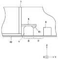
本発明の第1の実施形態におけるストレージライブラリ装置1について、図1乃至図6を参照して説明する。図1は、本発明の第1の実施形態におけるストレージライブラリ装置1の要部を示す上面図である。<First Embodiment>
The
図1において、ストレージライブラリ装置1は、大別して、マガジン2と、アクセッサ3とを有する。 In FIG. 1, the
より具体的に、マガジン2は、第1のプロテクトレバー4と、ロック部5と、ストッパー6、スロット7と、回転軸8とを有する。 More specifically, the
マガジン2は、ストレージ(つまり、記憶媒体)が格納されたカートリッジを収納可能な複数のスロットを有する。 The
尚、説明の便宜上、一例として、マガジン2は、1つのスロット7における動作について説明する。しかしながら本発明に係る実施形態は、係る構成に限定されず、マガジン2は、1つ以上のスロット7を有する構成を採用してもよい。 For convenience of explanation, the operation of the
また、説明及び図示の便宜上、図1において表現を省略したマガジン2は、例えば、+(プラス)Z軸方向にマガジンカバーを有することとする。さらに、マガジン2は、±(プラスマイナス)Y軸方向に延設されたマガジンベース40を有することとする(以下、本発明に係る各実施形態においても同様)。 For convenience of explanation and illustration, the
より具体的に、スロット7は、+(プラス)X軸方向に開口する面を前面とする。一方で、スロット7は、前面と対向するように−X軸方向に立設する側面を背面とする。また、スロット7は、+Y軸方向に立設する側面を右側面とする。一方で、スロット7は、右側面と対向するように−Y軸方向に立設する側面を左側面とする。さらに、スロット7は、−Z軸方向の平面を底面とする。一方で、マガジン2は、底面と対向する+Z軸方向の平面を上面(主面、天面)とする。 More specifically, the front surface of the
より具体的に、スロット7は、略正方形の形状を有する。スロット7における前面(図1において+X軸方向、紙面右手方向)は、ストレージが格納された不図示のカートリッジを挿脱可能に開口する形状に形成されている。 More specifically, the
即ち、当該カートリッジは、紙面左右方向(図1において±X軸方向)にスライドされることによって、スロット7から挿脱することができる。 That is, the cartridge can be inserted into and removed from the
尚、以下の説明において、説明の便宜上、代表的なカートリッジの一例として磁気テープカートリッジを用いて説明する。但し、本実施形態を例に説明する本発明は、これらに限定されない(以下、本発明に係る各実施形態においても同様)。 In the following description, for convenience of explanation, a magnetic tape cartridge is used as an example of a representative cartridge. However, the present invention described using this embodiment as an example is not limited thereto (hereinafter, the same applies to each embodiment according to the present invention).
また、説明の便宜上、一例として、スロット7は、略正方形の形状を有する構成を例に説明した。しかしながら本発明に係る実施形態は、係る構成に限定されず、スロット7は、磁気テープカートリッジの形状に合わせた形状を採用すればよい(以下、本発明に係る各実施形態においても同様)。 Further, for convenience of explanation, as an example, the
以下の説明において、説明の便宜上、本実施形態において説明するプロテクトレバーを第1のプロテクトレバー4と称する(以下、本発明に係る各実施形態においても同様)。 In the following description, for convenience of explanation, the protect lever described in the present embodiment is referred to as a first protect lever 4 (hereinafter, the same applies to each embodiment according to the present invention).
図2は、本発明の第1の実施形態における第1のプロテクトレバー4の構成を示す斜視図である。 FIG. 2 is a perspective view showing the configuration of the first
第1のプロテクトレバー4は、長手方向の一方(図2において+X軸方向)を略直線形状に形成されている。 The first
第1のプロテクトレバー4は、長手方向の上面における稜線(図2において+Z軸方向、上面における両角)を面取り処理が施されている。 The first
ここで、面取り処理は、係る突起部15が容易に第1のプロテクトレバー4における上面に乗り上げることが可能な程度に処理を施せばよい(以下、本発明に係る各実施形態においても同様)。 Here, the chamfering process may be performed to such an extent that the protruding
これにより、後述するロック部5における突起部15は、容易に第1のプロテクトレバー4における上面に乗り上げることができる。 Thereby, the
また、第1のプロテクトレバー4は、長手方向の一方(図2において+X軸方向)に回転軸8を中心軸として回動可能なように回転軸孔14が略円形状に形成されている。尚、回転軸孔14は、回転軸8を中心軸として、回動可能な大きさに設ければよい(回転軸8については、本実施形態において後述する)。 Further, the first
さらに、第1のプロテクトレバー4は、長手方向の他方(図2において−X軸方向)に第1の当接部12と第2の当接部13と略L字形状に形成された第1のブロック部11とを有する。 Further, the first
尚、上述した実施形態では、説明の便宜上、一例として、第1のブロック部11は、略L字形状に形成した構成を例に説明した。しかしながら本発明に係る実施形態は、係る構成に限定されず、第1のブロック部11は、不図示の磁気テープカートリッジの挿脱を阻止することが可能な形状を採用すればよい。その場合に、第1のブロック部11は、例えば、略直線形状を採用してもよい。但し、本実施形態を例に説明する本発明は、これらに限定されない(以下、本発明に係る各実施形態においても同様)。 In the above-described embodiment, as an example, the
図3は、本発明の第1の実施形態におけるマガジン2の要部を示す断面図(図1におけるA−A断面図)である。 FIG. 3 is a cross-sectional view (cross-sectional view taken along the line AA in FIG. 1) showing a main part of the
ロック部5は、スロット7における右側面からマガジンベース40と略平行(図3において+Y軸方向)となるようにスロット7における右側面の外側に突設されている。 The
さらに、ロック部5は、ロック部5の底面と第1のプロテクトレバー4の上面(図3における+Z軸方向)とが接するようにスロット7における右側面の外側に突設すればよい。但し、本実施形態を例に説明する本発明は、これらに限定されない(以下、本発明に係る各実施形態においても同様)。 Furthermore, the
また、ロック部5の材質には、ロック部5が第1のプロテクトレバー4の上面に乗り上げる際に変形すると共に、変形した後に元の形状に戻る弾性力と第1のプロテクトレバー4を固定することのできる強度とがあれば、金属、樹脂等の様々な材質を採用すればよい。 The
さらに、長手方向の一方(図3において+Y軸方向)にロック部5は、図3において−Z軸方向に向かって略円錐形状に形成された突起部15を有する。 Further, the
尚、上述した実施形態では、説明の便宜上、一例として、ロック部5は、略円錐形状に形成された突起部15を有する構成を例に説明した。しかしながら本発明に係る実施形態は、係る構成に限定されず、ロック部5は、略半円形状に形成された突起部15を有する構成を採用してもよい。但し、本実施形態を例に説明する本発明は、これらに限定されない(以下、本発明に係る各実施形態においても同様)。 In the embodiment described above, for the sake of convenience of explanation, as an example, the
ストッパー6は、略円柱状の形状を有する。また、ストッパー6は、マガジンベース40に設けられている。 The
尚、上述した実施形態では、説明の便宜上、一例として、ストッパー6は、略円柱状の形状を有する構成を例に説明した。しかしながら本発明に係る実施形態は、係る構成に限定されず、ストッパー6は、第1のプロテクトレバー4が当接することによって、当該第1のプロテクトレバー4が図1に示す+Y軸方向に回動することを抑止できる形状を採用すればよい(以下、本発明に係る各実施形態においても同様)。 In the above-described embodiment, for convenience of explanation, the
回転軸8は、略円柱状の形状を有する。また、回転軸8は、マガジンベース40に設けられている。回転軸8は、スロット7における右側面と第1のプロテクトレバー4における長手方向の側面とが略並列に近接する位置に設ければよい。 The
次に、アクセッサ3は、磁気テープドライブ(不図示)とマガジン2との間で磁気テープカートリッジ(不図示)を搬送する。 Next, the
より具体的に、アクセッサ3は、ピッカ9を有する。ピッカ9には、図1に示す如く+Y軸方向に略L字形状に形成されたピッカアーム10を有する。 More specifically, the
アクセッサ3は、ピッカ9を図1において±X軸方向に移動する動作と、アクセッサ3を図1において±Y軸方向に移動する動作とを組み合わせることによって、第1のプロテクトレバー4をピッカ9に形成されたピッカアーム10によって押動することができる。さらに、アクセッサ3は、磁気テープカートリッジを挿脱することができる。 The
尚、上述した実施形態では、説明の便宜上、一例として、ピッカアーム10は、略L字形状に形成する構成を例に説明した。しかしながら本発明に係る実施形態は、係る構成に限定されず、ピッカアーム10は、第1のプロテクトレバー4を押動することが可能な形状を採用すればよい。また、ピッカアーム10は、磁気テープカートリッジの挿脱機構に合わせた形状を採用してもよい。 In the embodiment described above, for convenience of explanation, the
また、上述した実施形態では、説明の便宜上、一例として、ピッカアーム10は、ピッカ9の一方(図1において+Y軸方向)に形成する構成を例に説明した。しかしながら本発明に係る実施形態は、係る構成に限定されず、ピッカアーム10は、ピッカ9の他方(図1において−Y軸方向)に形成する構成を採用してもよい(以下、本発明に係る各実施形態においても同様)。 In the embodiment described above, for the sake of convenience of explanation, as an example, the
次に、本発明の第1の実施形態に係るストレージライブラリ装置1のより具体的な動作について説明する。 Next, a more specific operation of the
ここでは、一例として、ストレージライブラリ装置1は、第1のプロテクトレバー4が使用可能な状態を示す位置から使用不可能な状態を示す位置に移動する際の動作について、詳細に説明する。 Here, as an example, the
以下に説明する例では、ストレージライブラリ装置1に通信ネットワークを介して接続されたサーバを管理者が操作することによって、スロット7を使用可能な状態から使用不可能な状態に設定するものとする。 In the example described below, it is assumed that the
また、ストレージライブラリ装置1は、管理者によって設定されたスロット7の使用可否(使用可能、又は使用不可能)の状態を、ストレージライブラリ装置1が有する不図示のコントローラ(外部装置、例えば、図8に示すコントローラ31)に保持(記憶)することとする。 Further, the
説明の便宜上、上述した構成を例に説明するが、本発明は、この構成例に限定されない(以下、本発明に係る各実施形態においても同様)。 For convenience of explanation, the configuration described above will be described as an example, but the present invention is not limited to this configuration example (hereinafter, the same applies to each embodiment according to the present invention).
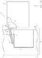
図4は、本発明の第1の実施形態において使用可能な状態を示す位置にある第1のプロテクトレバー4にアクセッサ3におけるピッカアーム10が当接した際の様態を例示する上面図である。 FIG. 4 is a top view illustrating a state when the
また、図5は、本発明の第1の実施形態におけるストレージライブラリ装置1が行うスロット7の使用可否の状態に応じて第1のプロテクトレバー4を移動する際の動作を示すフローチャートである。係るフローチャートに沿ってストレージライブラリ装置1の動作手順を説明する。 FIG. 5 is a flowchart showing an operation performed when the first
尚、以下の説明において、説明の便宜上、使用可能な状態を示す位置(つまり、図1に示すスロット7の右側面と第1のプロテクトレバー4の長手方向とが略平行に近接する位置、図3に示すP)を第1の位置Pと称する。また、使用不可能な状態を示す位置(つまり、図4に示すストッパー6と第1のプロテクトレバー4の長手方向とが当接する位置、図3に示すR)を第2の位置Rと称する(以下、本発明に係る各実施形態においても同様)。 In the following description, for convenience of description, a position indicating a usable state (that is, a position where the right side surface of the
ステップS1:
ストレージライブラリ装置1における不図示のコントローラは、スロット7の使用可否の状態を示す情報を保持するのに応じて、第1のプロテクトレバー4の位置を移動する指示をアクセッサ3に与える(出力する)。Step S1:
A controller (not shown) in the
ここでは、コントローラは、第1のプロテクトレバー4が使用可能な状態を示す位置から使用不可能な状態を示す位置(つまり、図3に示す第2の位置R)に移動する指示をアクセッサ3に出力する。 Here, the controller instructs the
ステップS2:
アクセッサ3は、取得した指示に応じて、第1のプロテクトレバー4とアクセッサ3におけるピッカアーム10とが当接可能な位置に移動する。Step S2:
The
さらに、アクセッサ3は、ピッカアーム10を図4において−X軸方向に移動することによって、第1のプロテクトレバー4における当接部(図2に示す第1の当接部12、または第2の当接部13)とピッカアーム10とを当接させる。 Further, the
より具体的に、第1のプロテクトレバー4を使用可能な状態から使用不可能な状態を示す位置(つまり、第2の位置R)に移動する場合に、アクセッサ3は、第1のプロテクトレバー4における第2の当接部13とピッカアーム10とが当接可能な位置に移動すると共に、ピッカアーム10を図4において−X軸方向に移動することによって、第2の当接部13とピッカアーム10とを当接させる。 More specifically, when the first
一方で、第1のプロテクトレバー4を使用不可能な状態から使用可能な状態を示す位置(つまり、図3に示す第1の位置P)に移動する場合に、アクセッサ3は、第1のプロテクトレバー4における第1の当接部12とピッカアーム10とが当接可能な位置に移動すると共に、ピッカアーム10を図4において−X軸方向に移動することによって、第1の当接部12とピッカアーム10とを当接させる。 On the other hand, when the first
ここでは、アクセッサ3は、第2の当接部13とピッカアーム10とが当接する位置に移動する。 Here, the
ステップS3:
アクセッサ3は、図4において±Y軸方向(図4において紙面上下方向)に自装置(アクセッサ3)を移動することによって、コントローラに保持されたスロット7の使用可否の状態を示す位置(つまり、第1の位置P、または第2の位置Rの何れかの位置)に第1のプロテクトレバー4を押動する。Step S3:
The
より具体的に、第1のプロテクトレバー4を使用可能な状態から使用不可能な状態を示す位置(つまり、第2の位置R)に移動する場合に、アクセッサ3は、自装置(アクセッサ3)を図4において−Y軸方向に移動することによって、第1のプロテクトレバー4を使用不可能な状態を示す位置に押動する。 More specifically, when the first
一方で、第1のプロテクトレバー4を使用不可能な状態から使用可能な状態を示す位置(つまり、第1の位置P)に移動する場合に、アクセッサ3は、自装置(アクセッサ3)を図4において+Y軸方向に移動することによって、第1のプロテクトレバー4を使用可能な状態を示す位置に押動する。 On the other hand, when the first
これにより、第1のプロテクトレバー4は、アクセッサ3によって押動された方向に回転軸8を中心として回動する。 As a result, the first
図6は、本発明の第1の実施形態において使用不可能な状態を示す位置にある第1のプロテクトレバー4の様態を例示する上面図である。 FIG. 6 is a top view illustrating the state of the first
ここでは、アクセッサ3は、自装置(アクセッサ3)を図6において−Y軸方向に移動することによって、第1のプロテクトレバー4を使用可能な状態から使用不可能な状態を示す位置に押動する。 Here, the
これにより、第1のプロテクトレバー4は、回転軸8を中心として図6において−Y軸方向に回動する。 As a result, the first
より具体的に、第1のプロテクトレバー4は、第2の当接部13とピッカアーム10とが当接すると共に、第2の当接部13が図6において−Y軸方向に押動されることによって、回転軸8を中心として図6に示す−Y軸方向に回動する。 More specifically, in the first
これにより、ロック部5の端部に設けられた突起部15(図3を参照)は、第1のプロテクトレバー4と交差した状態で同第1のプロテクトレバー4の上面に乗り上げる。即ち、ロック部5は、突起部15の高さ分(図3において+Z軸方向)変形する。 As a result, the protrusion 15 (see FIG. 3) provided at the end of the
さらに、突起部15が上記の如く交差した状態で第1のプロテクトレバー4における短手方向の端縁を通過した際に、ロック部5は、元の形状に戻る。さらに、第1のプロテクトレバー4は、スロット7における右側面と第1のプロテクトレバー4における長手方向の側面とが略並列になるように移動する。 Furthermore, when the
そのため、ロック部5は、突起部15によって第1のプロテクトレバー4を固定することができる。 Therefore, the
一方で、第1のプロテクトレバー4を使用不可能な状態から使用可能な状態を示す位置(つまり、第1の位置P)まで回動する場合に、第1のプロテクトレバー4は、第1の当接部12とピッカアーム10とが当接すると共に、第1の当接部12が図6において+Y軸方向に押動されることによって、回転軸8を中心として図6に示す+Y軸方向に回動する。 On the other hand, when the first
これにより、ロック部5の端部に設けられた突起部15(図3を参照)は、第1のプロテクトレバー4と交差した状態で同第1のプロテクトレバー4の上面を乗り上げる。 Thereby, the protrusion 15 (see FIG. 3) provided at the end of the
さらに、突起部15が上記の如く交差した状態で第1のプロテクトレバー4における短手方向の端縁を通過した際に、第1のプロテクトレバー4は、ストッパー6と当接する。さらに、ロック部5は、元の形状に戻る。 Furthermore, the first
そのため、ロック部5は、突起部15によって第1のプロテクトレバー4を固定することができる。 Therefore, the
尚、上述した実施形態では、説明の便宜上、一例として、ストレージライブラリ装置1は、第1のプロテクトレバー4をスロット7の右側(一方、図1において+Y軸側)に有する構成を例に説明した。しかしながら本発明に係る実施形態は、係る構成に限定されず、ストレージライブラリ装置1は、第1のプロテクトレバー4をスロット7の左側(他方、図1において−Y軸側)に有する構成を採用してもよい(以下、本発明に係る各実施形態においても同様)。 In the above-described embodiment, for convenience of explanation, the
このように本実施の形態に係るストレージライブラリ装置1によれば、マガジン2が有するスロット7の使用可否の状態に応じて、そのスロット7の使用可否の状態を示すことができる。 As described above, according to the
その理由は、ストレージライブラリ装置1は、第1のプロテクトレバー4がアクセッサ3に押動されることによってスロット7の使用可否の状態を示す位置に回動することができるからである。そのため、例えば、管理者は、マガジン2をストレージライブラリ装置1から取り外した場合においてもスロット7の使用可否の状態を即座に認識することができる。 The reason is that the
即ち、例えば、管理者は、スロット7に磁気テープカートリッジを挿入する際に、使用不可能なスロットを容易に目視で確認することができるため、挿脱する際の作業効率が向上することができる。 That is, for example, when the administrator inserts the magnetic tape cartridge into the
さらに、ストレージライブラリ装置1は、スロット7の使用不可能な状態に設定されている場合に、第1のプロテクトレバー4における第1のブロック部11によって磁気テープカートリッジの挿脱を阻止することができるからである。 Furthermore, when the
<第2の実施形態>
次に、上述した本発明の第1の実施形態に係るストレージライブラリ装置1を基本とする第2の実施形態について説明する。以下の説明においては、本実施形態に係る特徴的な部分を中心に説明する。その際、上述した各実施形態と同様な構成については、同一の参照番号を付すことにより、重複する説明は省略する。<Second Embodiment>
Next, a second embodiment based on the
本発明の第2の実施形態におけるストレージライブラリ装置1aについて、図7を参照して説明する。 A storage library apparatus 1a according to the second embodiment of the present invention will be described with reference to FIG.
図7は、本発明の第2の実施形態におけるストレージライブラリ装置1aの要部を示す上面図である。 FIG. 7 is a top view showing a main part of the storage library device 1a according to the second embodiment of the present invention.
図7において、ストレージライブラリ装置1aは、大別して、マガジン2と、アクセッサ20とを有する。 In FIG. 7, the storage library device 1 a roughly includes a
図7において、アクセッサ20は、第1の実施形態において説明したストレージライブラリ装置1におけるアクセッサ3に、さらに、アクセッサ20における左側面(−Y軸方向)にカメラ21を有する。 In FIG. 7, the
第1のプロテクトレバー4の位置を移動する指示を取得した際に、アクセッサ20は、カメラ21によって取得した第1のプロテクトレバー4の画像データを不図示のコントローラに出力する。 When the instruction to move the position of the first
尚、カメラ21によって第1のプロテクトレバー4の画像データを取得する技術自体は、現在では一般的な技術を採用することができるので、本実施形態における詳細な説明は省略する(以下、本発明に係る各実施形態においても同様)。 Note that the technique itself for acquiring the image data of the first
コントローラは、アクセッサ20から取得した第1のプロテクトレバー4の画像データに基づいて、第1のプロテクトレバー4の位置情報を抽出すると共に、抽出した位置情報と既に保持したスロット7の使用可否(使用可能、又は使用不可能)の状態を示す情報とを比較する。 The controller extracts the position information of the first
尚、コントローラが画像データに基づいて第1のプロテクトレバー4の位置を抽出する技術自体は、現在では一般的な技術を採用することができるので、本実施形態における詳細な説明は省略する(以下、本発明に係る各実施形態においても同様)。 Note that the technique itself by which the controller extracts the position of the first
コントローラは、比較した結果、第1のプロテクトレバー4の位置が同一と判定した場合に、処理を終了する。 As a result of the comparison, when the controller determines that the position of the first
一方で、コントローラは、比較した結果、第1のプロテクトレバー4の位置が異なると判定した場合に、第1のプロテクトレバー4の位置を移動する指示をアクセッサ20に出力する。 On the other hand, if the controller determines that the position of the first
尚、コントローラから第1のプロテクトレバー4の位置を移動する指示を取得した際の動作は、第1の実施形態において説明したアクセッサ3における動作と同様である。そのため、重複する説明は省略する。 The operation when the instruction to move the position of the first
また、上述した実施形態では、説明の便宜上、一例として、カメラ21は、アクセッサ20における−Y軸方向に有する構成を例に説明した。しかしながら本発明に係る実施形態は、係る構成に限定されず、カメラ21は、アクセッサ20における+Y軸方向に有する構成を採用してもよい(以下、本発明に係る各実施形態においても同様)。 Further, in the above-described embodiment, for the sake of convenience of explanation, the
このように本実施の形態に係るストレージライブラリ装置1aによれば、上述した第1の実施形態において説明した効果を享受できると共に、さらに、効率よく第1のプロテクトレバー4の位置を移動することができる。 As described above, according to the storage library device 1a according to the present embodiment, the effects described in the first embodiment can be enjoyed, and the position of the first
その理由は、アクセッサ20は、さらに、カメラ21を有する。そのため、コントローラは、カメラ21において取得した第1のプロテクトレバー4の画像データに基づいて、当該第1のプロテクトレバー4の位置を特定することができると共に、特定した位置と既に保持していた位置とが異なる場合に、第1のプロテクトレバー4の位置を移動することができるからである。 The reason is that the accessor 20 further includes a
(実施例)
次に、上述した本発明の第2の実施形態に係るストレージライブラリ装置1aを基本とする実施例について説明する。以下の説明においては、本実施例に係る特徴的な部分を中心に説明する。その際、上述した各実施形態と同様な構成については、同一の参照番号を付すことにより、重複する説明は省略する。(Example)
Next, an example based on the above-described storage library apparatus 1a according to the second embodiment of the present invention will be described. In the following description, the characteristic part according to the present embodiment will be mainly described. At this time, the same reference numerals are assigned to the same configurations as those in the above-described embodiments, and duplicate descriptions are omitted.
本発明の第2の実施形態に係る実施例における磁気テープライブラリ装置1bについて、図8及び図9を参照して説明する。 A magnetic
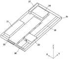
図8は、本発明の第2の実施形態に係る実施例における磁気テープライブラリ装置1bの構成を示す斜視図である。 FIG. 8 is a perspective view showing the configuration of the magnetic
図8において、磁気テープライブラリ装置1bは、大別して、コントローラ31と、マガジン32と、アクセッサ33と、磁気テープドライブ34と、ガイドレール35と、オペレーションパネル36と、電源37とを有する。 In FIG. 8, the magnetic
より具体的に、コントローラ31は、例えば、不図示のサーバ(管理端末)やオペレーションパネル36等を管理者からの操作に応じて、磁気テープドライブ34やアクセッサ33等の動作を制御する。また、コントローラ31は、磁気テープライブラリ装置1bにおける各種設定情報やマガジン32の状態を保持(記憶)する。 More specifically, the
さらに、コントローラ31は、アクセッサ33から取得した画像データに基づいて、第1のプロテクトレバー4の位置情報を抽出すると共に、抽出した第1のプロテクトレバー4の位置と既に保持したスロット7の使用可否(使用可能、又は使用不可能)の状態を示す情報とを比較する。 Further, the
これにより、コントローラ31は、比較した結果、第1のプロテクトレバー4の位置が同一と判定した場合に、処理を終了する。 Thereby, the
一方で、コントローラ31は、比較した結果、第1のプロテクトレバー4の位置が異なると判定した場合に、スロット7の第1のプロテクトレバー4の位置を移動する指示を示す信号をアクセッサ33に出力する。 On the other hand, if the
図9は、本発明の第2の実施形態に係る実施例におけるマガジン32における内部構成を示す斜視図である。 FIG. 9 is a perspective view showing an internal configuration of the
図9に示すマガジン32に上述した本発明の各実施形態に係るマガジン2を適用する。マガジン32は、第2の実施形態におけるマガジン2に相当する。このように、上述した本発明の各実施形態に係るマガジン2は、1つ以上のスロットがある場合に適用して好適である。
The
さらに、マガジン32は、図8において±Y軸方向にスライドすることによって、磁気テープライブラリ装置1bから挿脱することができる。 Further, the
これにより、例えば、管理者は、磁気テープライブラリ装置1bからマガジン32を取り出すと共に、マガジン32におけるスロット7に磁気テープカートリッジの交換作業を行うことができる。 Thereby, for example, the administrator can take out the
アクセッサ33は、第2の実施形態におけるアクセッサ20に相当する。アクセッサ33は、ガイドレール35を図8において±Y軸方向に走行する。 The
また、アクセッサ33は、マガジン32におけるスロット7から所望の磁気テープカートリッジを磁気テープドライブ34に搬送する。 Further, the
尚、アクセッサ33がガイドレール35を走行すると共に磁気テープドライブ34に搬送する技術自体は、現在では一般的な技術を採用することができるので、本実施形態における詳細な説明は省略する(以下、本発明に係る各実施形態においても同様)。 Incidentally, the technology itself that the accessor 33 travels on the
磁気テープドライブ34は、不図示の磁気テープカートリッジにおける磁気テープに対してデータの読み書きを行う。 The
尚、磁気テープドライブ34が磁気テープに対してデータの読み書きを行う技術自体は、現在では一般的な技術を採用することができるので、本実施形態における詳細な説明は省略する(以下、本発明に係る各実施形態においても同様)。 Note that the technology itself by which the
オペレーションパネル36は、例えば、管理者等から操作されることによって磁気テープライブラリ装置1bにおける各種設定や動作を実行することができる。 The
電源37は、磁気テープライブラリ装置1bに電力を供給するユニットである。 The
尚、電源37が磁気テープライブラリ装置1bに電力を供給する技術自体は、現在では一般的な技術を採用することができるので、本実施形態における詳細な説明は省略する(以下、本発明に係る各実施形態においても同様)。 Since the technology itself for supplying power to the magnetic
このように、本発明の第2の実施形態において説明したストレージライブラリ装置1aを磁気テープライブラリ装置1bに適用して好適である。 Thus, the storage library apparatus 1a described in the second embodiment of the present invention is preferably applied to the magnetic
尚、コントローラ31から第1のプロテクトレバー4の位置を移動する指示を示す信号を取得した際の動作は、各実施形態において説明したマガジン2とアクセッサ20とにおける動作と同様である。そのため、重複する説明は省略する。 The operation when acquiring a signal indicating an instruction to move the position of the first
このように本実施の形態に係る磁気テープライブラリ装置1bによれば、上述した各実施形態において説明した効果を享受できる。また、磁気テープライブラリ装置1bは、例えば、一般的に知られた磁気テープライブラリ装置に適用して好適である。 Thus, according to the magnetic
<第3の実施形態>
次に、上述した本発明の各実施形態に係るストレージライブラリ装置1aを基本とする第3の実施形態について説明する。以下の説明においては、本実施形態に係る特徴的な部分を中心に説明する。その際、上述した各実施形態と同様な構成については、同一の参照番号を付すことにより、重複する説明は省略する。<Third Embodiment>
Next, a third embodiment based on the storage library apparatus 1a according to each embodiment of the present invention described above will be described. In the following description, the characteristic part according to the present embodiment will be mainly described. At this time, the same reference numerals are assigned to the same configurations as those in the above-described embodiments, and duplicate descriptions are omitted.
第3の実施形態におけるストレージライブラリ装置1aが第2の実施形態において説明したストレージライブラリ装置1aと異なる点は、以下に述べる通りである。 The storage library apparatus 1a in the third embodiment is different from the storage library apparatus 1a described in the second embodiment as described below.
即ち、第3の実施形態におけるアクセッサ20は、予め定めたタイミングでカメラ21によって第1のプロテクトレバー4の画像データを取得すると共に、取得した画像データをコントローラ(例えば、図8に示すコントローラ31)に出力する。 That is, the
さらに、コントローラは、当該画像データに基づいて、第1のプロテクトレバー4の位置情報を抽出すると共に、抽出した位置情報と既に保持したスロット7の使用可否(使用可能、又は使用不可能)の状態を示す情報とを比較する。 Further, the controller extracts the position information of the first
また、コントローラは、既に保持したスロット7の使用可否の状態を示す情報と抽出した第1のプロテクトレバー4の位置情報とを比較した結果、第1のプロテクトレバー4の位置が異なると判定した場合に、コントローラに保持したスロット7の使用可否の状態を示す情報を抽出した第1のプロテクトレバー4の位置情報に書き換える。 In addition, when the controller determines that the position of the first
より具体的に、コントローラは、予め定めたタイミングで第1のプロテクトレバー4の画像データをコントローラに出力するように指示をアクセッサ20に出力する。 More specifically, the controller outputs an instruction to the accessor 20 to output the image data of the first
ここで、一例として、予め定めたタイミングとは、マガジン2をストレージライブラリ装置1aに装着した際や、所定の時刻とする。但し、本実施形態を例に説明する本発明は、これらに限定されない(以下、本発明に係る各実施形態においても同様)。 Here, as an example, the predetermined timing is a predetermined time when the
アクセッサ20は、取得した指示に応じて、カメラ21によって取得した第1のプロテクトレバー4の画像データをコントローラに出力する。 The accessor 20 outputs the image data of the first
コントローラは、アクセッサ20から取得した第1のプロテクトレバー4の画像データに基づいて、第1のプロテクトレバー4の位置を抽出すると共に、その抽出した位置情報と既に保持していたスロット7の使用可否の状態を示す情報とを比較する。 The controller extracts the position of the first
コントローラは、比較した結果、第1のプロテクトレバー4の位置が同一と判定した場合に、処理を終了する。 As a result of the comparison, when the controller determines that the position of the first
一方で、コントローラは、比較した結果、第1のプロテクトレバー4の位置が異なると判定した場合に、既に保持していたスロット7の使用可否の状態を示す情報を画像データに基づいて第1のプロテクトレバー4の位置を抽出した情報に書き換える。 On the other hand, if the controller determines that the position of the first
このように本実施の形態に係るストレージライブラリ装置1aによれば、上述した各実施形態において説明した効果を享受できると共に、さらに、効率よくスロット7の使用可否の状態を設定することができる。 As described above, according to the storage library device 1a according to the present embodiment, the effects described in the above-described embodiments can be enjoyed, and the availability state of the
その理由は、例えば、管理者によって磁気テープカートリッジを交換すると共に、マガジン2における第1のプロテクトレバー4を移動した際に、ストレージライブラリ装置1aは、第1のプロテクトレバー4の位置に基づいて、コントローラに記憶された使用可否の状態を変更することができるからである。 The reason is that, for example, when the administrator replaces the magnetic tape cartridge and moves the first
<第4の実施形態>
次に、上述した本発明の第2の実施形態に係るストレージライブラリ装置1aを基本とする第4の実施形態について説明する。以下の説明においては、本実施形態に係る特徴的な部分を中心に説明する。その際、上述した各実施形態と同様な構成については、同一の参照番号を付すことにより、重複する説明は省略する。<Fourth Embodiment>
Next, a fourth embodiment based on the storage library apparatus 1a according to the second embodiment of the present invention described above will be described. In the following description, the characteristic part according to the present embodiment will be mainly described. At this time, the same reference numerals are assigned to the same configurations as those in the above-described embodiments, and duplicate descriptions are omitted.
本発明の第4の実施形態におけるストレージライブラリ装置1cについて、図10乃至図12を参照して説明する。 A storage library apparatus 1c according to the fourth embodiment of the present invention will be described with reference to FIGS.
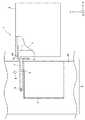
図10は、本発明の第4の実施形態におけるストレージライブラリ装置1cの要部を示す上面図である。 FIG. 10 is a top view showing the main part of the storage library device 1c in the fourth embodiment of the present invention.
尚、以下の説明において、説明の便宜上、本実施形態において説明するプロテクトレバーを第2のプロテクトレバー51と称する(以下、本発明に係る各実施形態においても同様)。 In the following description, for convenience of explanation, the protect lever described in the present embodiment is referred to as a second protect lever 51 (hereinafter, the same applies to each embodiment according to the present invention).
図10において、ストレージライブラリ装置1cは、上述した各実施形態において説明した第1のプロテクトレバー4を第2のプロテクトレバー51に変更した点が異なる。 In FIG. 10, the storage library device 1 c is different in that the first
より具体的に、ストレージライブラリ装置1cは、大別して、マガジン50と、第2の実施形態において説明したアクセッサ20とを有する。 More specifically, the storage library apparatus 1c roughly includes a
尚、説明及び図示の便宜上、図10乃至図12において表現を省略したストレージライブラリ装置1cは、+X軸方向に第2の実施形態において説明したアクセッサ20を有することとする。さらに、マガジン50は、+Y軸方向に延設されたスロット7を有することとする。 For the convenience of explanation and illustration, it is assumed that the storage library device 1c whose expression is omitted in FIGS. 10 to 12 includes the accessor 20 described in the second embodiment in the + X axis direction. Furthermore, the
マガジン50は、第2のプロテクトレバー51と、ロック部5と、ストッパー6、スロット7と、回転軸8とを有する。 The
図11は、本発明の第4の実施形態における第2のプロテクトレバー51の構成を示す斜視図である。 FIG. 11 is a perspective view showing the configuration of the second protect
より具体的に、第2のプロテクトレバー51は、第3の当接部53と、第2のブロック部52と、回転軸孔14とを有する。 More specifically, the second protect
第2のプロテクトレバー51は、略T字状に形成されている。第2のプロテクトレバー51は、長手方向の一方(図11において−X軸方向)に略円柱状に形成された第3の当接部53が立設している。 The second protect
第3の当接部53は、ピッカアーム10が当接すると共に、当該ピッカアーム10が第2のプロテクトレバー51を押動可能な高さ(図11において+Z軸方向)を採用すればよい。 The third abutting
尚、上述した実施形態では、説明の便宜上、一例として、第3の当接部53は、略円柱形状に形成する構成を例に説明した。しかしながら本発明に係る実施形態は、係る構成に限定されず、第3の当接部53は、ピッカアーム10が当接すると共に、当該ピッカアーム10が第2のプロテクトレバー51を押動可能な形状を採用すればよい。 In the above-described embodiment, for the sake of convenience of explanation, as an example, the
さらに、第2のプロテクトレバー51は、短手方向の一方(図11において−Y軸方向)に突出して設けられた凸部に略円柱形状に形成された第2のブロック部52が立設している。 Further, the second protect
また、第2のプロテクトレバー51は、長手方向の上面における稜線(図11において+Z軸方向、上面における両角)を面取り処理が施されている。 Further, the second protect
これにより、突起部15は、第2のプロテクトレバー51における上面を容易に乗り上げることができる。 Thereby, the
第2のプロテクトレバー51は、短手方向の一方(図11において+Y軸方向、第2のブロック部52と対向する)に回転軸8を中心軸として回動可能なように回転軸孔14が略円形状に形成されている。尚、回転軸孔14は、回転軸8を中心軸として、回動可能な大きさに設ければよい。 The second protect
次に、本発明の第4の実施形態に係るより具体的なストレージライブラリ装置1cの動作について説明する。 Next, a more specific operation of the storage library device 1c according to the fourth embodiment of the present invention will be described.
図12は、本発明の第4の実施形態におけるストレージライブラリ装置1cの要部とラッチ54の様態とを例示する斜視図である。 FIG. 12 is a perspective view illustrating the main part of the storage library device 1c and the state of the
ここでは、一例として、ストレージライブラリ装置1cは、第2のプロテクトレバー51が使用可能な状態を示す位置から使用不可能な状態を示す位置(つまり、図12に示す第2の位置R)に移動する際の動作について、詳細に説明する。 Here, as an example, the storage library device 1c moves from the position indicating the usable state of the second protect
説明の便宜上、上述した構成を例に説明するが、本発明は、この構成例に限定されない(以下、本発明に係る各実施形態においても同様)。 For convenience of explanation, the configuration described above will be described as an example, but the present invention is not limited to this configuration example (hereinafter, the same applies to each embodiment according to the present invention).
ここでは、一例として、スロット7は、磁気テープカートリッジをスロット7に固定するラッチ54を有することとする。 Here, as an example, the
より具体的に、一例として、ラッチ54は、スロット7における左側面に横設されており、長手方向の一方(図12において+X軸方向)に磁気テープカートリッジを収容する位置に突出するようラッチレバーが設けられている。 More specifically, as an example, the
そのため、例えば、管理者は、ラッチ54におけるラッチレバーを解除(図12において−Y軸方向)することによって、磁気テープカートリッジを挿脱することができる。即ち、管理者は、ラッチ54におけるラッチレバーを解除しない場合に、磁気テープカートリッジを挿脱することができない。 Therefore, for example, the administrator can insert and remove the magnetic tape cartridge by releasing the latch lever in the latch 54 (in the −Y axis direction in FIG. 12). That is, the administrator cannot insert or remove the magnetic tape cartridge unless the latch lever in the
また、ラッチ54の材質には、ラッチ54におけるラッチレバーを図12において−Y軸方向に力を加えた際に元の位置に戻る弾性力と磁気テープカートリッジを固定することのできる強度とがあれば、金属、樹脂等の様々な材質を採用すればよい。 Further, the material of the
アクセッサ20は、第3の当接部53とピッカアーム10とが当接可能な位置に移動する。 The accessor 20 moves to a position where the
さらに、アクセッサ20は、ピッカアーム10を図12に示す−X方向に移動することによって、第3の当接部53とピッカアーム10とを当接させる。 Further, the
より具体的に、第2のプロテクトレバー51を使用可能な状態から使用不可能な状態を示す位置(つまり、第2の位置R)に移動する場合に、アクセッサ20は、第3の当接部53における一方の側面(図12において−Y軸方向側)とピッカアーム10とが当接可能な位置に移動すると共に、ピッカアーム10を図12において−X軸方向に移動することによって、第3の当接部53における一方の側面(図12において−Y軸方向側)とピッカアーム10とを当接させる。 More specifically, when the second protect
一方で、第2のプロテクトレバー51を使用不可能な状態から使用可能な状態を示す位置(つまり、図12に示す第1の位置P)に移動する場合に、アクセッサ20は、第3の当接部53における他方の側面(図12において+Y軸方向側)とピッカアーム10とが当接可能な位置に移動すると共に、ピッカアーム10を図12において−X軸方向に移動することによって、第3の当接部53における他方の側面(図12において+Y軸方向側)とピッカアーム10とを当接させる。 On the other hand, when the second protect
ここでは、アクセッサ20は、第3の当接部53における一方の側面(図12において−Y軸方向側)とピッカアーム10とが当接する位置に移動する。 Here, the
アクセッサ20は、図12において±Y軸方向(図12において紙面左右方向)に自装置(アクセッサ20)を移動することによって、コントローラに保持されたスロット7の使用可否の状態を示す位置(つまり、第1の位置P、または第2の位置Rの何れかの位置)に第2のプロテクトレバー51を押動する。 The accessor 20 moves its own device (accessor 20) in the ± Y-axis direction (the left-right direction in FIG. 12) in FIG. 12, thereby indicating a position indicating whether or not the
より具体的に、第2のプロテクトレバー51を使用可能な状態から使用不可能な状態を示す位置(つまり、第2の位置R)に移動する場合に、アクセッサ20は、自装置(アクセッサ20)を図12において+Y軸方向に移動することによって、第2のプロテクトレバー51を使用不可能な状態を示す位置に押動する。 More specifically, when the second protect
一方で、第2のプロテクトレバー51を使用不可能な状態から使用可能な状態を示す位置(つまり、第1の位置P)に移動する場合に、アクセッサ20は、自装置(アクセッサ20)を図12において−Y軸方向に移動することによって、第2のプロテクトレバー51を使用可能な状態を示す位置に押動する。 On the other hand, when the second protect
ここでは、アクセッサ20は、自装置(アクセッサ20)を図12において+Y軸方向に移動することによって、第2のプロテクトレバー51を使用可能な状態から使用不可能な状態を示す位置に押動する。 Here, the
これにより、第2のプロテクトレバー51は、回転軸8を中心として図12において+Y軸方向に回動する。 As a result, the second protect
より具体的に、第2のプロテクトレバー51は、第3の当接部53における一方の側面(図12において−Y軸方向側)とピッカアーム10とが当接すると共に、第3の当接部53が図12において+Y軸方向に押動されることによって、回転軸8を中心として図12において+Y軸方向に回動する。 More specifically, the second protect
これにより、ロック部5の端部に設けられた突起部15は、第2のプロテクトレバー51と交差した状態で同第2のプロテクトレバー51の上面に乗り上げる。 As a result, the
さらに、突起部15が上記の如く交差した状態で第2のプロテクトレバー51における短手方向の端縁を通過した際に、第2のプロテクトレバー51は、ストッパー6と当接する。さらに、係るロック部5は、元の形状に戻る。そのため、ロック部5は、突起部15によって第2のプロテクトレバー51を固定することができる。 Furthermore, the second protect
また、第2のブロック部52は、ラッチ54と当接する。 Further, the
これにより、例えば、管理者は、第2のブロック部52とラッチ54とが当接しているために、ラッチ54におけるラッチレバーを解除することができない。 Thereby, for example, since the
即ち、スロット7が使用不可能な場合に、管理者は、第2のブロック部52がラッチ54と当接していることによって、ラッチ54におけるラッチレバーを解除することができない。つまり、ストレージライブラリ装置1cは、磁気テープカートリッジの挿脱を阻止することができる。 That is, when the
尚、第2のブロック部52は、ラッチ54と当接することが可能な高さ(図12において+Z軸方向)を採用すればよい。 Note that the
また、上述した実施形態では、説明の便宜上、一例として、第2のブロック部52は、略円柱形状に形成する構成を例に説明した。しかしながら本発明に係る実施形態は、係る構成に限定されず、第2のブロック部52は、ラッチ54と当接することが可能な形状を採用すればよい。 Further, in the above-described embodiment, for the sake of convenience of explanation, as an example, the
一方で、第2のプロテクトレバー51を使用不可能な状態から使用可能な状態を示す位置(つまり、第1の位置P)まで回動する場合に、第2のプロテクトレバー51は、第3の当接部53における他方の側面(図12において+Y軸方向側)とピッカアーム10とが当接すると共に、第3の当接部53(図12において+Y軸方向側)が図12において−Y軸方向に押動されることによって、回転軸8を中心として図12において−Y軸方向に回動する。 On the other hand, when the second protect
これにより、ロック部5の端部に設けられた突起部15は、第2のプロテクトレバー51と交差した状態で同第2のプロテクトレバー51の上面に乗り上げる。 As a result, the
さらに、突起部15が上記の如く交差した状態で第2のプロテクトレバー51における長手方向の端縁を通過した際に、第2のプロテクトレバー51における短手方向の一端は、スロット7における側面に当接する。さらに、係るロック部5は、元の形状に戻る。そのため、ロック部5は、突起部15によって第2のプロテクトレバー51を固定することができる。 Furthermore, when the
尚、説明の便宜上、一例として、本発明の第2の実施形態に係るストレージライブラリ装置1aを基本とする第4の実施形態について説明した。しかしながら本発明に係る実施形態は、係る構成に限定されず、本発明の第1の実施形態、第3の実施形態を基本とする構成を採用してもよい。 For convenience of explanation, the fourth embodiment based on the storage library device 1a according to the second embodiment of the present invention has been described as an example. However, the embodiment according to the present invention is not limited to such a configuration, and a configuration based on the first embodiment or the third embodiment of the present invention may be adopted.
このように本実施の形態に係るストレージライブラリ装置1cによれば、上述した各実施形態において説明した効果を享受できる。 Thus, according to the storage library device 1c according to the present embodiment, the effects described in the above-described embodiments can be enjoyed.
その理由は、スロット7が使用不可能な場合に、ストレージライブラリ装置1cは、第2のブロック部52がラッチ54と当接していることによって、ラッチ54におけるラッチレバーを解除することができない。そのため、ストレージライブラリ装置1cは、磁気テープカートリッジの挿脱を阻止することができる。 The reason is that when the
本発明は、上述した各実施形態には限定されない。本発明は、磁気テープや光ディスクなどのコンピュータ読み取り可能な記憶媒体が格納されたカートリッジだけでなく、様々なカートリッジを扱う複写機、複合機、ライブラリ装置等に適用可能である。 The present invention is not limited to the embodiments described above. The present invention is applicable not only to cartridges that store computer-readable storage media such as magnetic tapes and optical disks, but also to copiers, multifunction devices, library devices, and the like that handle various cartridges.
1 ストレージライブラリ装置
1a ストレージライブラリ装置
1b 磁気テープライブラリ装置
1c ストレージライブラリ装置
2 マガジン
3 アクセッサ
4 第1のプロテクトレバー
5 ロック部
6 ストッパー
7 スロット
8 回転軸
9 ピッカ
10 ピッカアーム
11 第1のブロック部
12 第1の当接部
13 第2の当接部
14 回転軸孔
15 突起部
20 アクセッサ
21 カメラ
31 コントローラ
32 マガジン
33 アクセッサ
34 磁気テープドライブ
35 ガイドレール
36 オペレーションパネル
37 電源
40 マガジンベース
50 マガジン
51 第2のプロテクトレバー
52 第2のブロック部
53 第3の当接部
54 ラッチDESCRIPTION OF
Claims (10)
Translated fromJapanese前記スロット近傍に設けられた回転軸と、
前記回転軸を中心軸として回動可能なプロテクトレバーと、
前記プロテクトレバーにおける短手方向の一端と当接した際に、さらに回動するのを防ぐ位置に設けられたストッパーとを備え、
前記プロテクトレバーは、前記カートリッジを搬送可能なアクセッサに押動されることにより、
前記スロットの使用可能な状態を示す第1の位置まで回動し、これによって前記ストッパーに当接すると共に前記ロック部によって固定され、
前記スロットの使用不可能な状態を示す第2の位置まで回動することによって、前記ロック部により固定される
ことを特徴とするライブラリ装置。A lock portion protruding from one or more side surfaces of the slot into which the cartridge can be inserted and removed;
A rotating shaft provided in the vicinity of the slot;
A protect lever that can be rotated around the rotation axis;
A stopper provided at a position to prevent further rotation when contacting the one end in the short direction of the protect lever;
The protect lever is pushed by an accessor capable of transporting the cartridge,
The slot is rotated to a first position indicating a usable state, thereby contacting the stopper and being fixed by the lock portion,
The library device is fixed by the lock portion by rotating to a second position indicating an unusable state of the slot.
前記第1の位置に回動する場合に、前記アクセッサが有するピッカアームと当接する第1の当接部と、
前記第2の位置に回動する場合に、前記ピッカアームと当接する第2の当接部と、
前記第2の位置に回動した際に、前記カートリッジの挿脱を阻止する第1のブロック部と、
を含むことを特徴とする請求項1に記載のライブラリ装置。The protect lever is
A first abutting portion that abuts on a picker arm included in the accessor when rotating to the first position;
A second contact portion that contacts the picker arm when rotating to the second position;
A first block for preventing insertion and removal of the cartridge when rotated to the second position;
The library apparatus according to claim 1, comprising:
前記第1の位置または前記第2の位置の何れかの位置に回動する場合に、前記アクセッサが有するピッカアームと当接する第3の当接部と、
前記第2の位置に回動した際に、前記カートリッジの挿脱を阻止する第2のブロック部とを含み、
前記第3の当接部は、
前記第1の位置に回動する場合に、前記ピッカアームと前記第3の当接部における一方の側面と当接し、一方で、前記第2の位置に回動する場合に、前記ピッカアームと前記第3の当接部における他方の側面と当接することを特徴とする請求項1に記載のライブラリ装置。The protect lever is
A third abutting portion that abuts on a picker arm included in the accessor when rotating to either the first position or the second position;
A second block portion that prevents insertion and removal of the cartridge when rotated to the second position;
The third contact portion is
When rotating to the first position, the picker arm contacts one side surface of the third contact portion, while when rotating to the second position, the picker arm and the third position The library apparatus according to claim 1, wherein the library apparatus abuts against the other side surface of the abutting portion.
前記第2のブロック部と前記スロットに設けられた前記カートリッジを固定するラッチと当接することによって、前記カートリッジの挿脱を阻止することを特徴とする請求項3に記載のライブラリ装置。The protect lever is
4. The library apparatus according to claim 3, wherein the cartridge is prevented from being inserted and removed by contacting the second block portion and a latch provided in the slot for fixing the cartridge.
さらに、前記プロテクトレバーの画像データを取得可能なカメラを前記アクセッサに有し、
前記カメラを有する前記アクセッサは、
外部装置から取得した前記画像データに基づく前記プロテクトレバーにおける位置を判定する処理結果に応じて、前記第1の位置または前記第2の位置の何れかの位置に前記プロテクトレバーを押動することを特徴とする請求項1乃至請求項4の何れかに記載のライブラリ装置。The library device
Furthermore, the accessor has a camera capable of acquiring image data of the protect lever,
The accessor having the camera is
The protect lever is pushed to either the first position or the second position in accordance with a processing result for determining the position of the protect lever based on the image data acquired from the external device. 5. The library apparatus according to claim 1, wherein the library apparatus is characterized in that:
前記カメラによって取得した前記画像データに基づいて、前記プロテクトレバーの位置情報を抽出すると共に、該抽出した位置情報と保持していた前記プロテクトレバーの位置を示す情報とを比較し、比較した結果、前記抽出した位置情報と保持していた前記プロテクトレバーの位置を示す情報とが異なる場合には、保持していた前記プロテクトレバーの位置を示す情報に基づいて、前記プロテクトレバーの位置を移動する指示を前記アクセッサに与える処理であることを特徴とする請求項5に記載のライブラリ装置。The process is
Based on the image data obtained by the camera, the position information of the protect lever is extracted, and the extracted position information is compared with the information indicating the position of the protect lever that has been held. If the extracted position information and the information indicating the position of the protect lever held are different from each other, an instruction to move the position of the protect lever based on the information indicating the position of the protect lever held. The library apparatus according to claim 5, wherein the library apparatus is a process for providing the accessor to the accessor.
さらに、前記画像データに基づいて、前記位置を判定する処理を実行し、その判定結果に
応じて、前記外部装置に保持していた前記プロテクトレバーの位置を示す情報を前記抽出
した位置情報に書き換えることを特徴とする請求項6に記載のライブラリ
装置。The library device
Further, a process for determining the position is executed based on the image data, and information indicating the position of the protect lever held in the external device is rewritten to the extracted position information according to the determination result. The library apparatus according toclaim 6 .
自装置の動作を制御するコントローラであることを特徴とする請求項5に記載のライブラリ装置。The external device is
The library apparatus according to claim 5, wherein the library apparatus is a controller that controls the operation of the own apparatus.
前記ロック部の端部に設けられた突起部が前記プロテクトレバーと交差した状態で、そのプロテクトレバーの上面に乗り上げると共に、その交差した状態で前記プロテクトレバーの短手方向の端縁を通過した際に、前記プロテクトレバーを固定することを特徴とする請求項1乃至請求項8の何れかに記載のライブラリ装置。When rotated to either the first position or the second position by being pushed by the accessor,
When the protrusion provided at the end of the lock portion crosses the protect lever and rides on the upper surface of the protect lever, and passes the edge in the short direction of the protect lever in the crossed state 9. The library apparatus according to claim 1, wherein the protect lever is fixed to the library apparatus.
Priority Applications (2)
| Application Number | Priority Date | Filing Date | Title |
|---|---|---|---|
| JP2012244965AJP6060628B2 (en) | 2012-11-07 | 2012-11-07 | Library device |
| US14/070,735US9293167B2 (en) | 2012-11-07 | 2013-11-04 | Library apparatus |
Applications Claiming Priority (1)
| Application Number | Priority Date | Filing Date | Title |
|---|---|---|---|
| JP2012244965AJP6060628B2 (en) | 2012-11-07 | 2012-11-07 | Library device |
Publications (2)
| Publication Number | Publication Date |
|---|---|
| JP2014093115A JP2014093115A (en) | 2014-05-19 |
| JP6060628B2true JP6060628B2 (en) | 2017-01-18 |
Family
ID=50622426
Family Applications (1)
| Application Number | Title | Priority Date | Filing Date |
|---|---|---|---|
| JP2012244965AActiveJP6060628B2 (en) | 2012-11-07 | 2012-11-07 | Library device |
Country Status (2)
| Country | Link |
|---|---|
| US (1) | US9293167B2 (en) |
| JP (1) | JP6060628B2 (en) |
Families Citing this family (3)
| Publication number | Priority date | Publication date | Assignee | Title |
|---|---|---|---|---|
| JP6395228B2 (en)* | 2016-03-24 | 2018-09-26 | Necプラットフォームズ株式会社 | Library apparatus, cartridge pop-out prevention mechanism and method |
| US10616652B2 (en)* | 2016-08-04 | 2020-04-07 | Novatek Microelectronics Corp. | Playback method and electronic device using the same |
| US12254897B1 (en)* | 2022-09-07 | 2025-03-18 | MagNext Ltd. | Data cartridge magazine and library system |
Family Cites Families (13)
| Publication number | Priority date | Publication date | Assignee | Title |
|---|---|---|---|---|
| JPH0626039U (en)* | 1992-08-24 | 1994-04-08 | アイワ株式会社 | Stopper device such as cartridge |
| US5576911A (en) | 1994-10-25 | 1996-11-19 | Sony Corporation | Cartridge locking mechanism and interface |
| JPH09212984A (en) | 1996-02-02 | 1997-08-15 | Canon Inc | Optical disc changer |
| JP3555520B2 (en) | 1999-09-27 | 2004-08-18 | 日本電気株式会社 | Medium control device and control method for medium control device |
| JP2002296654A (en)* | 2001-03-30 | 2002-10-09 | Fuji Photo Optical Co Ltd | Camera |
| JP2005521112A (en) | 2001-07-06 | 2005-07-14 | コンピュータ アソシエイツ シンク,インコーポレイテッド | Information backup system and method |
| JP2003226059A (en) | 2002-02-04 | 2003-08-12 | Sharp Corp | Image forming device |
| JP4818161B2 (en) | 2007-02-27 | 2011-11-16 | 富士通株式会社 | Storage protection mechanism |
| JP4947017B2 (en) | 2008-09-11 | 2012-06-06 | 日本電気株式会社 | Library device, method for detecting position of recording medium, magazine |
| WO2011092826A1 (en)* | 2010-01-28 | 2011-08-04 | 富士通株式会社 | Cartridge magazine for library device, and library device |
| JP5205422B2 (en)* | 2010-07-28 | 2013-06-05 | シャープ株式会社 | Toner cartridge and image forming apparatus using the same |
| JP5596481B2 (en)* | 2010-09-28 | 2014-09-24 | Necエンベデッドプロダクツ株式会社 | Library device |
| JP5516479B2 (en)* | 2011-03-31 | 2014-06-11 | 日本電気株式会社 | Library device |
- 2012
- 2012-11-07JPJP2012244965Apatent/JP6060628B2/enactiveActive
- 2013
- 2013-11-04USUS14/070,735patent/US9293167B2/enactiveActive
Also Published As
| Publication number | Publication date |
|---|---|
| JP2014093115A (en) | 2014-05-19 |
| US9293167B2 (en) | 2016-03-22 |
| US20140126774A1 (en) | 2014-05-08 |
Similar Documents
| Publication | Publication Date | Title |
|---|---|---|
| JP2566725B2 (en) | Stacker / autoloader device with magazine control | |
| JP5782767B2 (en) | Library device | |
| JP2012526338A (en) | Optical disk storage system | |
| JP6060628B2 (en) | Library device | |
| US6895300B2 (en) | Use of cartridge memory for storing logical library association information | |
| US8180987B2 (en) | Encrypt-only data storage cartridge | |
| US7694884B2 (en) | Removable cartridge identification system | |
| JPH0798920A (en) | Library device | |
| JP2010152993A (en) | Library device and its storage medium management method, and program | |
| JP6751007B2 (en) | Information presentation mechanism, storage device, library device, and information presentation method | |
| JP3683552B2 (en) | Medium input device | |
| JP4585571B2 (en) | Cartridge magazine and cartridge library apparatus | |
| JP2008217966A (en) | Tape media drive, media drive controller, and method for sensing if reel of storage device is released | |
| JP3987542B2 (en) | Medium input device | |
| JP3823937B2 (en) | Medium control apparatus, medium control method, and program thereof | |
| JP4277877B2 (en) | Autoloader device, library device, and cartridge loading method for library device | |
| JP4360576B2 (en) | Single reel type tape cartridge | |
| JP4028537B2 (en) | How to manage parts | |
| US12125499B1 (en) | Magnetic media decommission management in a computer system | |
| JP2012243346A (en) | Medium library device, medium information management method and medium information management program | |
| CN101197170B (en) | Storage medium housing device | |
| US8879199B2 (en) | Locking mechanism and library apparatus | |
| JP6989415B2 (en) | Lock mechanism, movable object moving device, control method of movable object moving device, and control program of movable object moving device | |
| JP6485879B2 (en) | Library control apparatus and library control method | |
| JP2005243074A (en) | Library system and its magazine mechanism |
Legal Events
| Date | Code | Title | Description |
|---|---|---|---|
| A621 | Written request for application examination | Free format text:JAPANESE INTERMEDIATE CODE: A621 Effective date:20151015 | |
| A977 | Report on retrieval | Free format text:JAPANESE INTERMEDIATE CODE: A971007 Effective date:20160809 | |
| A131 | Notification of reasons for refusal | Free format text:JAPANESE INTERMEDIATE CODE: A131 Effective date:20160830 | |
| A521 | Written amendment | Free format text:JAPANESE INTERMEDIATE CODE: A523 Effective date:20161024 | |
| TRDD | Decision of grant or rejection written | ||
| A01 | Written decision to grant a patent or to grant a registration (utility model) | Free format text:JAPANESE INTERMEDIATE CODE: A01 Effective date:20161115 | |
| A61 | First payment of annual fees (during grant procedure) | Free format text:JAPANESE INTERMEDIATE CODE: A61 Effective date:20161128 | |
| R150 | Certificate of patent or registration of utility model | Ref document number:6060628 Country of ref document:JP Free format text:JAPANESE INTERMEDIATE CODE: R150 |