JP6057678B2 - Mobile terminal device, program, and control method for mobile terminal device - Google Patents
Mobile terminal device, program, and control method for mobile terminal deviceDownload PDFInfo
- Publication number
- JP6057678B2 JP6057678B2JP2012252379AJP2012252379AJP6057678B2JP 6057678 B2JP6057678 B2JP 6057678B2JP 2012252379 AJP2012252379 AJP 2012252379AJP 2012252379 AJP2012252379 AJP 2012252379AJP 6057678 B2JP6057678 B2JP 6057678B2
- Authority
- JP
- Japan
- Prior art keywords
- incoming call
- message
- unit
- area
- terminal device
- Prior art date
- Legal status (The legal status is an assumption and is not a legal conclusion. Google has not performed a legal analysis and makes no representation as to the accuracy of the status listed.)
- Active
Links
Images


Landscapes
- Telephone Function (AREA)
- Mobile Radio Communication Systems (AREA)
Description
Translated fromJapanese本発明は、携帯電話機、PDA(Personal Digital Assistant)、タブレットPC(Tablet PC)、電子書籍端末等の携帯端末装置に関する。また、本発明は、かかる携帯端末装置に用いて好適なプログラムおよび制御方法に関する。 The present invention relates to a mobile terminal device such as a mobile phone, a PDA (Personal Digital Assistant), a tablet PC (Tablet PC), and an electronic book terminal. The present invention also relates to a program and a control method suitable for use in such a mobile terminal device.
従来、海外等において、携帯電話機を使用するためにあらかじめ契約された回線事業者以外の基地局の電波を用いて通信や通話ができるローミングサービスが提供されている(たとえば、特許文献1参照)。通常、ローミングサービスを用いて通話をする場合は、自身の基地局の電波を用いて通話する場合に比べて、発信者側に高額な通話料金が発生する。 2. Description of the Related Art Conventionally, roaming services that allow communication and telephone calls using radio waves of base stations other than a line operator contracted in advance to use a mobile phone have been provided overseas (see, for example, Patent Document 1). Usually, when a call is made using a roaming service, a higher call charge is generated on the caller side than when a call is made using the radio waves of its own base station.
従来、ローミングサービスが提供可能な携帯電話機では、ローミングサービスが提供されるエリア(ローミングエリア)に携帯電話機があることが電波の受信状態に応じて判別され、ピクト領域の電波アイコンの表示がローミングエリアに対応するアイコンの表示に切り替えられる。 Conventionally, in a mobile phone that can provide a roaming service, it is determined that there is a mobile phone in an area (roaming area) where the roaming service is provided according to the reception state of the radio wave, and the radio wave icon display in the pictogram area is displayed You can switch to the icon display corresponding to.
上記の携帯電話機では、ピクト領域における電波アイコンの表示は小さいため、ユーザは、ローミングサービスによる着信と気付かずに受話してしまうことが生じ得る。
また、発信者は、発信時に相手がローミングエリアにいることが分からない。この場合、発信者に対して、不用意に高額な通話料を発生させてしまうとの問題が生じる。In the mobile phone described above, since the radio wave icon is displayed in the pictogram area, the user may receive the call without noticing the incoming call by the roaming service.
In addition, the caller does not know that the other party is in the roaming area when making a call. In this case, there arises a problem that an expensive call charge is inadvertently generated for the caller.
そこで、本発明は、発信者に対する不用意な課金の発生を抑えることが可能な携帯端末装置、プログラムおよび携帯端末装置の制御方法を提供することを目的とする。 Accordingly, an object of the present invention is to provide a mobile terminal device, a program, and a control method for the mobile terminal device that can suppress the occurrence of inadvertent billing for a caller.
本発明の第1の態様に係る携帯端末装置は、表示面を有する表示部と、電話の着信に関する電波を受け付ける着信受付部と、前記着信受付部が受け付けた電話の着信に関する電波の受信状態を検知する受信状態検知部と、ユーザによる操作を受け付ける操作受付部と、記憶部と、着信制御部と、を備える。ここで、前記記憶部は、前記着信受付部が前記電波を前記ローミングエリアで受信したことを通知する第1のメッセージを記憶する。さらに、前記着信制御部は、前記着信受付部が前記電波をローミングエリアで受信したことを前記受信状態検知部が検知した場合、前記第1のメッセージを通知するための操作の対象となる第1のオブジェクトを含む第1の着信画面を前記表示面に表示させ、前記第1のオブジェクトに対する操作に応じて、前記電話の発信者に前記第1のメッセージを通知し、前記着信受付部が前記電波をホームエリアで受信したことを前記受信状態検知部が検知した場合、第2の着信画面を前記表示面に表示させる。A mobile terminal device according to a first aspect of the present invention includes a display unit having a display surface, an incoming call reception unit that receives radio waves related to incoming calls, and a reception state of radio waves related to incoming calls received by the incoming call reception unit. A reception state detection unit to detect, anoperation reception unit that receivesan operation by auser, a storage unit, and an incoming call control unit. Here, the storage unit stores a first message notifying that the incoming call reception unit has received the radio wave in the roaming area. Further, the incoming call control unit is afirst operation target for notifying the first message when the reception state detection unit detects that the incoming call reception unit has received the radio wave in a roaming area. A first incoming call screenincluding theobject is displayed on the display surface,the first message is notified to the caller of the telephone in response to an operation on the first object, and the incoming call reception unit receives the radio wave. the case where the reception state detection unit that it has received the home area is detected,Ru display the second incoming screen on the displaysurface.
このような構成とした場合、前記着信制御部は、前記第1のオブジェクトに対する操作
に応じて、前記第1のメッセージが入力された電子メールを前記電話の発信者に送信するような構成とされ得る。In such a configuration, the incoming call control unit is configured to send an e-mail in which the first message is input to the caller in response to an operation on the first object. obtain.
あるいは、前記着信制御部は、前記第1のオブジェクトに対する操作に応じて、前記第1のメッセージが入力された、前記電話の発信者宛の電子メールの編集画面を前記表示面に表示するような構成とされ得る。 Alternatively, the incoming call control unit displays, on the display surface, an edit screen for an e-mail addressed to the caller of the telephone, in which the first message is input, in response to an operation on the first object. It can be configured.
本態様に係る携帯端末装置において、前記記憶部は、前記第1のメッセージの通知相手を特定するため判定条件を記憶するような構成とされ得る。この場合、前記着信制御部は、前記判定条件に合致する前記電話の発信者に前記第1のメッセージを通知する。 In the mobile terminal device according to this aspect, the storage unit may be configured to store a determination condition for specifying a notification partner of the first message. In this case, the incoming call control unit notifies the first message to the caller of the telephone that matches the determination condition.
このような構成とした場合、前記着信制御部は、前記電話の発信者の電話番号が前記判定条件に合致する場合、前記第1のオブジェクトを前記第1の着信画面に表示し、前記電話の発信者の電話番号が前記判定条件に合致しない場合、前記第1のオブジェクトを前記第1の着信画面に表示しないような構成とされ得る。 In such a configuration, the incoming call control unit displays the first object on the first incoming call screen when the telephone number of the caller of the telephone matches the determination condition, and If the telephone number of the caller does not match the determination condition, the first object may not be displayed on the first incoming screen.
本態様に係る携帯端末装置において、前記記憶部は、ユーザが前記ローミングエリアから前記ホームエリアに戻ったことを通知する第2のメッセージを記憶するとともに、該第2のメッセージの通知相手を特定するための情報を登録するための登録領域を備えるような構成とされ得る。この場合、前記第1の着信画面は、前記第2のメッセージを通知するための操作の対象となる第2のオブジェクトを含み、前記着信制御部は、前記第2のオブジェクトに対する操作に応じて、前記電話の発信者の情報を前記登録領域に登録するとともに、前記受信状態検知部が、前記着信受付部が前記ローミングエリアで電波を受信したことを検知した後に前記着信受付部が前記ホームエリアで電波を受信したことを検知したときに、前記第2のメッセージを通知する。 In the mobile terminal device according to this aspect, the storage unit stores a second message notifying that the user has returned from the roaming area to the home area, and specifies a notification partner of the second message. For example, it may be configured to include a registration area for registering information for the purpose. In this case, the first incoming call screen includes a second object that is a target of an operation for notifying the second message, and the incoming call control unit responds to an operation on the second object, The caller information is registered in the registration area, and after the reception state detection unit detects that the incoming call reception unit has received radio waves in the roaming area, the incoming call reception unit is in the home area. The second message is notified when it is detected that a radio wave has been received.
このような構成とした場合、前記着信制御部は、前記受信状態検知部が、前記着信受付部が前記ローミングエリアで電波を受信したことを検知した後に前記着信受付部が前記ホームエリアで電波を受信したことを検知したときに、前記電話の発信者に前記第2のメッセージが入力された電子メールを送信するような構成とされ得る。 In such a configuration, the incoming call control unit is configured such that after the reception state detection unit detects that the incoming call reception unit has received radio waves in the roaming area, the incoming call reception unit transmits radio waves in the home area. When the reception is detected, an e-mail in which the second message is input may be transmitted to the caller of the telephone.
本態様に係る携帯端末装置において、前記記憶部は、ユーザが前記ローミングエリアから前記ホームエリアに戻ったことを通知する第3のメッセージを記憶するような構成とされ得る。この場合、前記着信制御部は、前記受信状態検知部が、前記着信受付部が前記ローミングエリアで電波を受信したことを検知した後に前記着信受付部が前記ホームエリアで電波を受信したことを検知したときに、前記第3のメッセージを前記表示面に表示する。 In the mobile terminal device according to this aspect, the storage unit may be configured to store a third message notifying that the user has returned from the roaming area to the home area. In this case, the incoming call control unit detects that the incoming call reception unit has received radio waves in the home area after the reception state detection unit has detected that the incoming call reception unit has received radio waves in the roaming area. When this is done, the third message is displayed on the display surface.
本態様に係る携帯端末装置において、前記記憶部は、前記着信受付部が前記電波を前記ローミングエリアで受信したことを通知する第4のメッセージを記憶するような構成とされ得る。この場合、前記着信制御部は、前記第2のオブジェクトに対する操作に応じて、前記電話の発信者に前記第4のメッセージを通知する。 In the mobile terminal device according to this aspect, the storage unit may be configured to store a fourth message notifying that the incoming call reception unit has received the radio wave in the roaming area. In this case, the incoming call controller notifies the fourth message to the caller in response to an operation on the second object.
このような構成とした場合、前記着信制御部は、前記着信受付部が前記ローミングエリアで電波を受信したことを前記受信状態検知部が検知した後に通話した前記電話の発信者には前記第4のメッセージを通知しないような構成とされ得る。 In such a configuration, the incoming call control unit sends the fourth caller to the caller who made a call after the reception state detection unit detects that the incoming call reception unit has received radio waves in the roaming area. The message may not be notified.
本態様に係る携帯端末装置において、前記第1の着信画面は、前記電話の発信者に電子メールを送信するための操作の対象となる第3のオブジェクトを含み、前記着信制御部は、前記第3のオブジェクトに対する操作に応じて、前記電話の発信者宛の電子メールの編集画面を前記表示面に表示するような構成とされ得る。In the mobile terminal device according to the present embodiment, the first incoming screen includes athird objectthat Do the operation target for sending e-mail to the originator of the telephone, the call control unit, the An editing screen for an e-mail addressed to the caller of the telephone may be displayed on the display surface in response to an operation on the third object.
本発明の第2の態様に係る携帯端末装置は、表示面を有する表示部と、電話の着信に関する電波を受け付ける着信受付部と、前記着信受付部が受け付けた電話の着信に関する電波の受信状態を検知する受信状態検知部と、ユーザによる操作を受け付ける操作受付部と、記憶部と、着信制御部と、を備える。ここで、前記記憶部は、ユーザが前記ローミングエリアから前記ホームエリアに戻ったことを通知するメッセージを記憶するとともに、該メッセージの通知相手を特定するための情報を登録するための登録領域を備える。前記着信制御部は、前記着信受付部が前記電波をローミングエリアで受信したことを前記受信状態検知部が検知した場合、前記メッセージを通知するための操作の対象となるオブジェクトを含む第1の着信画面を前記表示面に表示させ、前記オブジェクトに対する操作に応じて、前記電話の発信者の情報を前記登録領域に登録するとともに、前記受信状態検知部が、前記着信受付部が前記ローミングエリアで電波を受信したことを検知した後に前記着信受付部が前記ホームエリアで電波を受信したことを検知したときに、前記メッセージを通知し、前記着信受付部が前記電波をホームエリアで受信したことを前記受信状態検知部が検知した場合、第2の着信画面を前記表示面に表示させる。A mobile terminal device according to asecond aspect of the present invention includesa display unit having adisplay surface, an incoming call reception unit that receives radio waves related to incoming calls, and a reception state of radio waves related to incoming calls received by the incoming call reception unit. A reception state detection unit to detect, an operation reception unitthat receives an operation bya user, a storage unit, and anincoming call control unit .Here, the storage unit, the user stores the notification toRume message that has returned to the home area of the roaming area, registration for registering information for identifying a notification destination of該Me message Provide an area.The incoming call control unit includes a first incoming call including an object that is an operation target for notifying the message when the reception state detection unit detects that the incoming call reception unit has received the radio wave in a roaming area. to display the screen on the display surface, previous response to an operation toKio object, and registers the information of the originator of the telephone in the registration area, the reception state detection unit, the incoming call receiving unit is the roaming area in when the incoming call receiving unit after detecting the reception of the radio wave detects the reception of the radio wave in the home area, prior to notifying thetexture message,the incoming call receiving unit receives the radio wave in the home area When the reception state detecting unit detects that the second incoming call screen is detected, a second incoming call screen is displayed on the display surface.
本発明の第3の態様に係るプログラムは、表示面を有する表示部と、電話の着信に関する電波を受け付ける着信受付部とを備える携帯端末装置のコンピュータに、前記着信受付部が受け付けた電話の着信に関する電波の受信状態を検知する機能と、前記着信受付部が前記電波をローミングエリアで受信したことを検知した場合、前記着信受付部が前記電波を前記ローミングエリアで受信したことを通知する第1のメッセージを通知するための操作の対象となる第1のオブジェクトを含む第1の着信画面を前記表示面に表示させ、前記第1のオブジェクトに対する操作に応じて、前記電話の発信者に前記第1のメッセージを通知する機能と、
前記着信受付部が前記電波をホームエリアで受信したことを検知した場合、第2の着信画面を前記表示面に表示させる機能と、を実行させる。According to athird aspect of the present invention, there is provided a program for receiving an incoming call received by the incoming call reception unit in a computer of a portable terminal device including a display unit having a display surface and an incoming call reception unit for receiving radio waves related to incoming calls. A function for detecting the reception state of the radio wave, and a first notification that the incoming call reception unit has received the radio wave in the roaming area when theincoming call reception unit detects that theradio wave has been received in the roaming area. A first incoming call screenincluding a first object that is a target of an operation for notifying the message is displayed on the display surface,and in response to an operation on the first object, the caller of the telephone is A function to notify one message,
If the incoming call receiving unit detects the reception of the electric wave in the home area,to execute the function of displaying the second incoming screen on the display surface.
本発明の第4の態様は、表示面を有する表示部と、電話の着信に関する電波を受け付ける着信受付部と、制御部とを備える携帯端末装置の制御方法に関する。本態様に係る制御方法は、前記着信受付部が受け付けた電話の着信に関する電波の受信状態を前記制御部が検知するステップと、前記着信受付部が前記電波をローミングエリアで受信したことを検知した場合、前記制御部が、前記着信受付部が前記電波を前記ローミングエリアで受信したことを通知する第1のメッセージを通知するための操作の対象となる第1のオブジェクトを含む第1の着信画面を前記表示面に表示させ、前記第1のオブジェクトに対する操作に応じて、前記電話の発信者に前記第1のメッセージを通知するステップと、前記着信受付部が前記電波をホームエリアで受信したことを検知した場合、前記制御部が、第2の着信画面を前記表示面に表示させるステップと、を含む。A4th aspect of this invention is related with the control method of a portable terminal device provided with the display part which has a display surface, the incoming call reception part which receives the electromagnetic wave regarding the incoming call of a telephone, anda control part . In the control method according to this aspect, thecontrol unit detects a reception state of a radio wave related to an incoming call received by the incoming call reception unit, and detects that the incoming call reception unit has received the radio wave in a roaming area. In this case, thecontrol unit includes a first incoming screenthat includes a firstobject that is an operation target for notifying the first message notifying that the incoming call reception unit has received the radio wave in the roaming area. And displayingthe first message to the caller in response to an operation on the first object, and the incoming call reception unit receiving the radio wave in the home area. Thecontroller includes a step of displaying a second incoming call screen on the display surface.
本発明によれば、発信者に対する不用意な課金の発生を抑えることが可能な携帯端末装置、プログラムおよび携帯端末装置の制御方法を提供することができる。 ADVANTAGE OF THE INVENTION According to this invention, the control method of the portable terminal device which can suppress generation | occurrence | production of careless charge with respect to a sender | caller, a program, and a portable terminal device can be provided.
本発明の効果ないし意義は、以下に示す実施形態の説明によりさらに明らかとなろう。ただし、以下の実施形態は、あくまでも、本発明を実施化する際の一つの例示であって、本発明は、以下の実施形態に記載されたものに何ら制限されるものではない。 The effects and significance of the present invention will become more apparent from the following description of embodiments. However, the following embodiment is merely an example when the present invention is implemented, and the present invention is not limited to what is described in the following embodiment.
以下、本発明の実施形態について、図面を参照して説明する。 Hereinafter, embodiments of the present invention will be described with reference to the drawings.
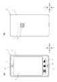
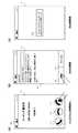
図1は、携帯電話機1の構成を示す図である。図1(a)および(b)は、それぞれ、携帯電話機1の正面図および背面図である。 FIG. 1 is a diagram showing a configuration of the
以下、説明の便宜上、図1に示すように、キャビネット2の長手方向を上下方向と定義し、キャビネット2の短手方向を左右方向と定義する。 Hereinafter, for convenience of explanation, as shown in FIG. 1, the longitudinal direction of the
携帯電話機1は、キャビネット2と、表示面3と、マイクロフォン4と、通話スピーカ5と、キー操作部6と、外部スピーカ7とを備えている。 The
キャビネット2は、正面から見て、ほぼ長方形状を有する。キャビネット2の正面に、後述する表示部13の表示面3が配されている。表示面3には、各種の画像(画面)が表示される。 The
キャビネット2の内部には、下端部にマイクロフォン4が配されており、上端部に通話スピーカ5が配されている。マイクロフォン4には、キャビネット2の正面に形成されたマイク孔4aを通じて音声が入力される。マイクロフォン4は、入力した音に応じた電気信号を生成する。通話スピーカ5からは、音声が出力される。出力された音声は、キャビネット2の正面に形成された出力孔5aを通じて外部に放出される。 Inside the
キャビネット2の正面には、キー操作部6が設けられている。キー操作部6は、複数の操作キーから構成されている。各操作キーには、実行中のプログラムを操作するための各種の機能が割り当てられる。 A
キャビネット2の内部には、外部スピーカ7が配されている。キャビネット2の背面には、外部スピーカ7に対応する出力孔7aが形成されている。外部スピーカ7から出力された音(音声、報知音等)は、出力孔7aを通じて外部に放出される。 An
図2は、携帯電話機1の全体構成を示すブロック図である。携帯電話機1は、制御部11と、記憶部12と、表示部13と、タッチ検出部14と、音声入力部15と、音声出力部16と、音声処理部17と、キー入力部18と、通信部19を備えている。 FIG. 2 is a block diagram showing the overall configuration of the
記憶部12は、ROM、RAM、外部メモリー等から構成される。記憶部12には、各種のプログラムが記憶されている。記憶部12に記憶されるプログラムは、携帯電話機1の各部を制御するための制御プログラムの他、各種アプリケーション(たとえば、電話、電子メール、電話帳、地図、ゲーム、スケジュール管理、等)を含む。プログラムは、メーカによって携帯電話機1の製造時に記憶部12に記憶される他、ユーザによって通信網やメモリカード等の記憶媒体を介して記憶部12に記憶される。 The
記憶部12には、プログラムの実行の際、一時的に利用または生成されるデータを記憶する図示しないワーキング領域も含まれる。 The
記憶部12には、図3(a)に示す電話帳テーブル12aが記憶されている。電話帳テーブル12aには、通信相手の連絡先情報が登録されている。連絡先情報は、名前、電話番号、メールアドレス、住所等の通信相手に係る連絡先の情報、および、通信相手に関連する画像、通信相手の誕生日、通信相手の趣味等の通信相手に係るその他の情報により構成される。各連絡先情報には登録番号が付されている。 The
ユーザは、電話帳のアプリケーションを実行し、所定の登録画面を用いて通信相手毎に連絡先情報を入力する。入力された連絡先情報が電話帳テーブル12aに登録される。 The user executes a phone book application and inputs contact information for each communication partner using a predetermined registration screen. The input contact information is registered in the telephone book table 12a.
また、記憶部12には、図3(b)に示す着信履歴テーブル12bが記憶されている。着信履歴テーブル12bには、着信があった日時と発信者の電話番号が対応付けられて登録されている。着信履歴テーブル12bは、所定の回数分の着信履歴を登録するための容量を有しており、容量の上限に到達した場合、最も古い着信履歴から順に着信履歴が削除される。 Further, the
さらに、記憶部12には、後述するローミングエリア通知機能に利用されるローミングエリア通知メッセージテンプレート12cが記憶されている。ローミングエリア通知メッセージテンプレート12cは、現在、ユーザが、ローミングエリアにいることを通知するための所定の文字列である。 Further, the
制御部11は、CPU等から構成されている。制御部11は、プログラムに従って、携帯電話機1を構成する各部(記憶部12、表示部13、タッチ検出部14、音声入力部15、音声出力部16、音声処理部17、キー入力部18、通信部19等)を制御する。 The
表示部13は、液晶ディスプレイ等から構成される。表示部13は、制御部11からの制御信号と画像信号に基づき、表示面3に画像(画面)を表示する。表示部13は、液晶ディスプレイに限らず、有機ELディスプレイ等、他の表示装置から構成されてもよい。 The
タッチ検出部14は、表示面3への指の接触を検出するタッチパネル等から構成されている。タッチパネルは、透明なシート状に形成され、表示面3上を覆いキャビネット2の正面に配される。タッチパネルは、静電容量式、超音波式、感圧式、抵抗膜式、光検知式等、各種方式のタッチパネルであってよい。 The
タッチ検出部14は、前記表示面3へのユーザによるタッチ操作を受け付ける。具体的には、タッチ検出部14は、ユーザの指が触れた表示面3上の位置、即ち、タッチ位置を検出し、検出したタッチ位置に応じた位置信号を制御部11へ出力する。 The
ユーザは、表示面3に指を触れることにより各種のタッチ操作を行うことができる。タッチ操作の種類として、タップ操作、フリック操作、スライド操作、ロングタップ操作等が挙げられる。タップ操作は、表示面3に指を接触させた後、短時間のうちに表示面3より指を離す操作である。フリック操作は、表示面3を指で任意の方向に弾く操作である。スライド操作は、表示面3に指を接触させたまま任意の方向へ移動させる操作である。フリック操作およびスライド操作は、タッチ位置の移動を伴うタッチ操作である。ロングタップ操作は、表示面3に指を接触させた後、しばらくの間接触を維持し、表示面3から指を離す操作である。 The user can perform various touch operations by touching the
タッチ操作についてより具体的に説明する。たとえば、タッチ検出部14により表示面3に対するタッチ位置が検出された後、予め定めた第1時間以内にタッチ位置が検出されなくなった場合、即ち、表示面3より指を離す操作があった場合、制御部11によりタップ操作がなされたと判定される。タッチ検出部14により表示面3に対するタッチ位置が検出され、予め定めた第2時間以内に予め定めた第1距離以上タッチ位置が移動した後、タッチ位置が検出されなくなった場合、制御部11によりフリック操作がなされたと判定される。タッチ検出部14により表示面3に対するタッチ位置が検出された後、予め定めた第2距離以上タッチ位置が移動すると、制御部11によりスライド操作がなされたと判定される。タッチ検出部14により表示面3に対するタッチ位置が検出された後、予め定めた第3時間以上タッチ位置が検出され続け、さらにその後、タッチ位置が検出されなくなった場合、制御部11によりロングタップ操作がなされたと判定される。 The touch operation will be described more specifically. For example, after the touch position on the
音声入力部15は、マイクロフォン4等から構成される。音声入力部15は、マイクロフォン4からの電気信号を音声処理部17へ出力する。 The
音声出力部16は、通話スピーカ5および外部スピーカ7を含む。音声出力部16には、音声処理部17からの電気信号が入力され、通話スピーカ5または外部スピーカ7から音(音声、報知音等)が出力される。 The
音声処理部17は、音声入力部15からの電気信号にA/D変換等を施し、変換後のデジタルの音声信号を制御部11へ出力する。音声処理部17は、制御部11からのデジタルの音声信号にデコード処理およびD/A変換等を施し、変換後の電気信号を音声出力部16に出力する。 The
キー入力部18は、キー操作部6の各操作キーが押下されたときに、押下された操作キーに応じた信号を制御部11へ出力する。 The
通信部19は、通話や通信を行うための信号を変換するための回路や電波を送受信するアンテナ等を備える。通信部19は、制御部11から入力される通話や通信のための信号を無線信号に変換し、変換された無線信号を、アンテナを介して基地局や他の通信装置等の通信先へ送信する。さらに、通信部19は、アンテナを介して受信した無線信号を制御部11が利用できる形式の信号へ変換し、変換された信号を制御部11へ出力する。 The
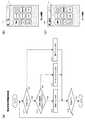
図4(a)は、制御部11が実行する電波の受信状態を検知するための制御処理の手順を示すフローチャートである。図4(b)、図4(c)は、電波受信状態における表示面3の画面表示例を示す図である。 FIG. 4A is a flowchart illustrating a procedure of control processing for detecting the reception state of the radio wave executed by the
携帯電話機1が起動されると、たとえば、図4(b)、図4(c)に示すように、表示面3に、初期画面であるホーム画面が表示される。表示面3に表示される領域のうち、上部のピクト領域には、電池残量や電波受信状態、現在時刻などが表示される。下部の表示領域には、各種アプリケーションを起動するためのアイコン等が表示される。 When the
図4(a)の制御処理は、携帯電話機1の起動により開始され、各アプリケーションの制御処理等、他の制御処理とともに、並列して実行される。 The control process of FIG. 4A is started by the activation of the
携帯電話機1が起動されると、まず、制御部11は、電波を受信できるか否かを判定する(S11)。制御部11は、電波を受信できると判断した場合(S11:YES)、制御部11は、受信した電波に、携帯電話機1を使用するためにあらかじめ契約された回線事業者の基地局の電波が含まれるか否かを判定する(S12)。以下、携帯電話機1を使用するためにあらかじめ契約された回線事業者の基地局の電波を受信できるエリアを、「ホームエリア」と称する。また、携帯電話機1を使用するために契約された回線事業者の基地局の電波を受信できず、且つ、それ以外の基地局の電波を受信できるエリアを、「ローミングエリア」と称する。 When the
携帯電話機1を使用するために契約された回線事業者の基地局の電波が含まれる場合(S12:YES)、制御部11は、図4(b)に示すように、ピクト領域に電波アイコン101を表示する(S13)。電波アイコン101には、ホームエリアを示すマークと、受信した電波の強度に応じた縦の線が含まれる。受信した電波の強度が強いほど、縦の線の本数が多く、弱いほど、縦の線の本数が少ない。 When the radio wave of the base station of the line operator contracted to use the
携帯電話機1を使用するために契約された回線事業者の基地局の電波が含まれない場合(S12:NO)、制御部11は、図4(c)に示すように、ピクト領域にローミングアイコン102を表示する(S14)。ローミングアイコン102には、ローミングエリアを示すマークと、受信した電波の強度に応じた縦の線が含まれる。なお、ローミングエリアを示すマークは、図4(c)に示すマークのほか、たとえば、“Rm”の文字が含まれていても良い。 When the radio wave of the base station of the line operator contracted to use the
制御部11は、電波を受信できないと判断した場合(S11:NO)、表示面3上のピクト領域に圏外アイコンを表示する(S15)。圏外アイコンには、たとえば、“圏外”の文字が含まれる。 When determining that the radio wave cannot be received (S11: NO), the
制御部11は、携帯電話機1の電源がオフされない限り(S16:NO)、処理をS11に戻し、携帯電話機1の電源がオフされるまでS11〜S15の処理を繰り返す。 The
このような処理により、携帯電話機1の電波の受信状況に応じて、制御部11によって、ホームエリアを示す電波アイコン101と、ローミングエリアを示すローミングアイコン102と、圏外を示す圏外アイコンの表示が切り替えられる。したがって、ユーザは、ピクト領域を確認することにより、受信している電波が、ホームエリアで受信された電波であるか、ローミングエリアで受信された電波であるかを把握することができる。 By such processing, the display of the
しかし、図4(b)、図4(c)に示すように、電波アイコン101、ローミングアイコン102のサイズは、表示面3全体のサイズに対して小さい。したがって、電話の着信
時において、ユーザが、ホームエリアかローミングエリアかを瞬時に判断することは困難な場合がある。特に、ローミングエリアで着信した場合、発信者に高額な通信費が発生するため、ローミングエリアで誤って受話した場合、発信者に大きな費用負担が生じることとなる。However, as shown in FIGS. 4B and 4C, the size of the
そこで、本実施の形態の携帯電話機1は、電波の受信状態に応じて、着信画面を切り替える機能を備えている。 Therefore, the
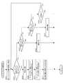
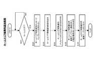
図5は、着信制御処理の手順を示すフローチャートである。 FIG. 5 is a flowchart showing a procedure of incoming call control processing.
図5の着信制御処理は、携帯電話機1の起動により開始され、各アプリケーションの制御処理等、他の制御処理とともに、並列して実行される。 The incoming call control process of FIG. 5 is started by the activation of the
携帯電話機1が起動されると、まず、制御部11は、他の機器から通信部19へ着信があるか否かを判定する(S21)。通信部19に着信がない場合(S21:NO)、制御部11は、携帯電話機1の電源がオフされない限り(S22:NO)、処理を待機させる。 When the
他の機器から通信部19へ着信があると(S21:YES)、制御部11は、受信している電波がローミングエリアの電波であるか否かを判定する(S23)。具体的には、図4(a)に示した処理により、電波アイコン101が表示されている状態であるのか、ローミングアイコン102が表示されている状態であるのかを判定する。 When there is an incoming call from another device to the communication unit 19 (S21: YES), the
受信している電波がローミングエリアの電波でない場合(S23:NO)、すなわち、受信している電波がホームエリアの電波である場合、制御部11は、ホームエリアに応じた着信の制御処理を行う(S24)。受信している電波がローミングエリアの電波の場合(S23:YES)、制御部11は、ローミングエリアに応じた着信の制御処理を行う(S25)。 When the received radio wave is not a roaming area radio wave (S23: NO), that is, when the received radio wave is a home area radio wave, the
図6は、ホームエリアに応じた着信の制御処理の手順を示すフローチャートである。図7は、ローミングエリアに応じた着信の制御処理の手順を示すフローチャートである。 FIG. 6 is a flowchart showing a procedure of incoming call control processing corresponding to the home area. FIG. 7 is a flowchart showing a procedure of incoming call control processing corresponding to a roaming area.
制御部11は、受信した電波がホームエリアの電波であると判断すると(S23:NO)、図8(a)に示すように、ホームエリア着信画面H1を表示面3に表示する(S101)。他方、制御部11は、受信した電波がローミングエリアの電波であると判断すると(S23:YES)、図9(a)に示すように、ローミングエリア着信画面R1を表示面3に表示する(S201)。 When the
図8(a)は、ホームエリア着信画面H1を示す図である。図8(b)ないし図8(d)は、ホームエリア着信画面H1からの画面遷移の例を示す図である。図9(a)は、ローミングエリア着信画面R1を示す図である。図9(b)は、ローミングエリア着信画面R1からの画面遷移例を示す図である。 FIG. 8A shows a home area incoming screen H1. FIG. 8B to FIG. 8D are diagrams showing examples of screen transition from the home area incoming screen H1. FIG. 9A shows the roaming area incoming screen R1. FIG. 9B is a diagram showing an example of screen transition from the roaming area incoming screen R1.
図8(a)を参照して、ホームエリア着信画面H1には、着信中であることを示すメッセージと、発信者の電話番号と、電話帳テーブル12aに登録された電話番号に対応する名前が表示される。ホームエリア着信画面H1には、受話アイコン111と、拒否アイコン112と、メッセージ通知アイコン113が配されている。受話アイコン111には、着信中の電話に応答するための機能が割り当てられている。拒否アイコン112には、着信を切断する機能が割り当てられている。メッセージ通知アイコン113には、着信を切断し、発信者の電話番号宛にSMS(Short Message Service)を送信するための機能が
割り当てられている。Referring to FIG. 8A, on home area incoming screen H1, a message indicating that a call is being received, the telephone number of the caller, and the name corresponding to the telephone number registered in telephone directory table 12a are displayed. Is displayed. On the home area incoming screen H1, an
また、図9(a)を参照して、ローミングエリア着信画面R1では、ローミングエリア着信中であることを示すメッセージと、発信者の電話番号と、電話帳テーブル12aに登録された電話番号に対応する名前が表示される。ローミングエリア着信画面R1には、受話アイコン111と、拒否アイコン112と、ローミングエリア通知アイコン114が配されている。ローミングエリア通知アイコン114には、着信を切断し、発信者の電話番号宛に携帯電話機1がローミングエリアにいることを伝えるためのメッセージが記載されたSMS(Short Message Service)を送信する機能が割り当てられている。 Referring to FIG. 9A, the roaming area incoming screen R1 corresponds to a message indicating that the roaming area is being received, the telephone number of the caller, and the telephone number registered in the telephone book table 12a. The name to be displayed is displayed. On the roaming area incoming screen R1, a
まず、ホームエリア着信画面H1における各機能の制御について説明する。 First, control of each function in the home area incoming screen H1 will be described.
図6を参照して、ホームエリア着信画面H1を表示すると(S101)、制御部11は、メッセージ通知アイコン113に対してタップ操作がなされたか否かを判定する(S102)。メッセージ通知アイコン113に対してタップ操作がなされていない場合(S102:NO)、制御部11は、受話アイコン111に対してタップ操作がなされたか否かを判定する(S103)。受話アイコン111に対してタップ操作がなされていない場合(S103:NO)、制御部11は、拒否アイコン112に対してタップ操作がなされたか否かを判定する(S104)。拒否アイコン112に対してタップ操作がなされていない場合(S104:NO)、制御部11は、着信が終了したか否かを判定する(S105)。そして、着信が終了していない場合(S105:NO)、制御部11は、処理をS102に戻し、各アイコンに対するタップ操作状況の判定処理(S102〜S104)を繰り返す。 Referring to FIG. 6, when home area incoming screen H1 is displayed (S101),
受話アイコン111に対してタップ操作がなされると(S103:YES)、制御部11は、通話処理を行う(S106)。通話処理は、たとえば、表示面3に通話画面を表示する処理、通信先の電話機との通信網の確立、受話音声の入出力処理、通話終了処理等、を含む。拒否アイコン112に対してタップ操作がなされると(S104:YES)、制御部11は、着信を切断する(S107)。 When a tap operation is performed on the reception icon 111 (S103: YES), the
メッセージ通知アイコン113に対してタップ操作がなされると(S102:YES)、制御部11は、着信を切断し(S108)、図8(b)に示すように表示面3にSMS作成画面を表示する(S109)。SMS作成画面には、SMSの内容を編集するための編集領域W1と、送信ボタン121と、キャンセルボタン122が含まれている。 When a tap operation is performed on the message notification icon 113 (S102: YES), the
SMS作成画面を表示すると、制御部11は、編集領域W1に対してタップ操作がなされたか否かを判定する(S110)。編集領域W1に対してタップ操作がなされると(S110:YES)、制御部11は、編集領域W1のメッセージ編集処理を行う(S111)。メッセージ編集処理には、たとえば、ユーザによるソフトウェアキーボード入力に応じた文字の入出力制御が含まれる。ユーザは、表示面3に表示されたソフトウェアキーボードにより、メッセージを入力する。たとえば、図8(c)に示すように、現在、電話に出られないことを伝えるメッセージを入力する。 When the SMS creation screen is displayed, the
メッセージ編集処理が完了すると、または、編集領域W1に対してタップ操作がなされていない場合(S110:NO)、制御部11は、送信ボタン121に対してタップ操作がなされたか否かを判定する(S112)。送信ボタン121に対してタップ操作がなされていない場合(S112:NO)、制御部11は、キャンセルボタン122に対してタップ操作がなされたか否かを判定する(S113)。キャンセルボタン122に対してタップ操作がなされていない場合(S113:NO)、制御部11は、処理をS110に戻し、ユーザによるメッセージ編集待ちの処理と、各ボタンに対するタップ操作状況の判定
処理を繰り返す(S110〜S113)。When the message editing process is completed, or when the tap operation has not been performed on the editing area W1 (S110: NO), the
送信ボタン121に対してタップ操作がなされると(S112:YES)、制御部11は、発信者の電話番号宛にSMSを送信する(S114)。これにより、図8(d)に示すように、表示面3にSMS送信画面が表示される。SMS送信画面には、たとえば、SMSを送信したことを伝えるメッセージが記載されたSMS送信ウィンドウ201が含まれる。キャンセルボタン122に対してタップ操作がなされた場合(S113:YES)、制御部11は、SMSの送信を中止し、表示面3のSMSの作成画面の表示を終了する。 When a tap operation is performed on the send button 121 (S112: YES), the
こうして、各機能の制御処理が完了すると、制御部11は、処理をS21に戻し、次の着信を待つ。 Thus, when the control process for each function is completed, the
図10(a)、図10(b)は、発信者の携帯電話機501の表示面502に表示されるSMS受信画面の表示例を示す図である。なお、携帯電話機501は携帯電話機1と同様の構成を有しているが、実施例の説明のために受信者の携帯電話機と発信者の携帯電話機とを区別して別の構成番号を付与した。 FIG. 10A and FIG. 10B are diagrams showing a display example of the SMS reception screen displayed on the
上述のようにして、携帯電話機1のホームエリア着信画面H1にて、メッセージ通知アイコン113に対してタップ操作がなされ、SMSが送信されると、図10(a)に示すように、携帯電話機1がローミングエリアにあるときに発信した発信者の携帯電話機501の表示面502には、SMS受信画面が表示される。 As described above, when the tap operation is performed on the
このように、ホームエリアでの着信時には、ユーザは、メッセージ通知アイコン113に対してタップ操作を行うことにより、SMSを作成することができ、発信者に任意のメッセージを通知することができる。 Thus, when an incoming call is received in the home area, the user can create an SMS by performing a tap operation on the
次に、ローミングエリア着信画面R1における各機能の制御について説明する。本実施の形態の携帯電話機1のローミングエリア着信画面R1では、携帯電話機1がローミングエリアにいることを発信者に迅速に通知する機能が実行される。 Next, control of each function in the roaming area incoming screen R1 will be described. In the roaming area incoming screen R1 of the
図7を参照して、ローミングエリア着信画面R1を表示すると(S201)、制御部11は、ローミングエリア通知アイコン114に対してタップ操作がなされたか否かを判定する(S202)。ローミングエリア通知アイコン114に対してタップ操作がなされていない場合(S202:NO)、制御部11は、ホームエリア着信時の制御処理と同様に、着信が終了しない限り(S205:NO)、受話アイコン111に対するタップ操作状況(S203)、拒否アイコン112に対するタップ操作状況(S204)の判定処理を繰り返す。 Referring to FIG. 7, when roaming area incoming screen R1 is displayed (S201),
受話アイコン111に対してタップ操作がなされると(S203:YES)、制御部11は、通話処理を行い(S206)、拒否アイコン112に対してタップ操作がなされると(S204:YES)、制御部11は、着信を切断する(S207)。 When a tap operation is performed on the reception icon 111 (S203: YES), the
ローミングエリア通知アイコン114に対してタップ操作がなされると(S202:YES)、制御部11は、着信を切断し(S208)、図2に示す記憶部12にあらかじめ記憶されたローミングエリア通知メッセージテンプレート12cからローミングエリア通知メッセージを読み出す(S209)。そして、制御部11は、ローミングエリア通知メッセージが入力されたSMSを作成し(S210)、発信者の電話番号宛にSMSを送信する(S211)。これにより、図9(b)に示すように、表示面3にSMS送信画面が表示される。SMS送信画面には、たとえば、ローミングエリアを通知するSMSを送信
したことを伝えるメッセージが記載されたSMS送信ウィンドウ202が含まれる。When a tap operation is performed on the roaming area notification icon 114 (S202: YES), the
こうして、各機能の制御処理が完了すると、制御部11は、処理をS21に戻し、次の着信を待つ。 Thus, when the control process for each function is completed, the
上述のようにして、携帯電話機1のローミングエリア着信画面R1にて、ローミングエリア通知アイコン114に対してタップ操作がなされ、自動的にローミングエリア通知メッセージが記載されたSMSが送信されると、図10(b)に示すように、携帯電話機1がローミングエリアにあるときに発信した発信者の携帯電話機501の表示面502には、SMS受信画面が表示される。 As described above, when the tap operation is performed on the roaming
以上、本実施の形態によれば、電波の受信状態に応じて、ホームエリア着信画面H1とローミングエリア着信画面R1が切り替えられて表示されるため、ユーザは、ローミングエリアでの着信を迅速、且つ、適正に判断することができる。これにより、発信者に対する不用意な課金の発生を抑えることができる。 As described above, according to the present embodiment, the home area incoming call screen H1 and the roaming area incoming screen R1 are switched and displayed according to the reception state of radio waves, so that the user can quickly receive incoming calls in the roaming area, and Can be judged properly. Thereby, it is possible to suppress the occurrence of inadvertent billing for the caller.
さらに、本実施の形態によれば、ローミングエリアでの着信時に、ローミングエリア通知アイコン114に対してタップ操作を行うことにより、あらかじめ記憶部12に記憶されたローミングエリア通知メッセージが記載されたSMSが自動的に送信される。これにより、ユーザは、メッセージを入力する手間を省くことができ、携帯電話機1がローミングエリアにいることを、発信者に迅速に通知することができる。なお、緊急の場合は、受話アイコン111に対するタップ操作を行うことにより発信者と通話することができる。 Furthermore, according to the present embodiment, when an incoming call is made in the roaming area, by performing a tap operation on the roaming
<変更例1>
上記実施の形態では、ローミングエリア通知アイコン114に対するタップ操作がなされると、ローミングエリア通知メッセージが記載されたSMSが自動的に送信されたが、変更例1では、ローミングエリア通知メッセージが記載されたSMS作成画面が表示面3に表示される。<
In the above-described embodiment, when a tap operation is performed on the roaming
図11は、変更例1に係る、ローミングエリアに応じた着信の制御処理の手順を示すフローチャートである。図11は、図7のフローチャートを一部変更するものであり、変更された処理を含む一部の処理のみが示されている。図12(a)〜図12(c)は、変更例1に係る、ローミングエリア着信画面R1からの画面遷移例を示す図である。 FIG. 11 is a flowchart illustrating a procedure of incoming call control processing according to a roaming area according to the first modification. FIG. 11 shows a partial modification of the flowchart of FIG. 7 and shows only a part of the processing including the modified processing. FIGS. 12A to 12C are diagrams illustrating screen transition examples from the roaming area incoming screen R1 according to the first modification.
以下、変更例1のローミングエリアに応じた着信制御処理について説明する。上記実施の形態と同じ処理については、同じステップ番号を付し、説明を省略する。 Hereinafter, the incoming call control process according to the roaming area of the first modification will be described. The same processes as those in the above embodiment are denoted by the same step numbers, and description thereof is omitted.
ローミングエリア着信画面R1において、ローミングエリア通知アイコン114に対してタップ操作がなされると(S202:YES)、制御部11は、着信を切断し(S208)、記憶部12に記憶されたローミングエリア通知メッセージテンプレート12cからローミングエリア通知メッセージを読み出す(S209)。そして、制御部11は、図12(b)に示すように、ローミングエリア通知メッセージが入力されたSMS作成画面を表示面3に表示する(S221)。SMS作成画面には、ホーム着信画面H1におけるSMS作成画面と同様に、SMSの内容を編集するための編集領域W1と、送信ボタン121と、キャンセルボタン122が含まれている。編集領域W1には、記憶部12から読み出されたローミングエリア通知メッセージが入力されている。 When a tap operation is performed on the roaming
SMS作成画面を表示すると、制御部11は、編集領域W1に対してタップ操作がなされたか否かを判定する(S222)。編集領域W1に対してタップ操作がなされると(S222:YES)、制御部11は、編集領域W1のメッセージ編集処理を行う(S223
)。メッセージを追加したい場合、ユーザは、ソフトウェアキーボードにより、メッセージを追加する。たとえば、ユーザは、帰国予定日や時間等を追加入力することができる。または、メッセージを変更したい場合、ユーザは、ソフトウェアキーボードにより、発信者に伝えたいメッセージを変更する。When the SMS creation screen is displayed, the
). When adding a message, the user adds a message using a software keyboard. For example, the user can additionally input a scheduled return date, time, and the like. Alternatively, when the user wants to change the message, the user changes the message to be transmitted to the caller using the software keyboard.
メッセージ編集処理が完了すると、または、編集領域W1に対してタップ操作がなされていない場合(S222:NO)、制御部11は、送信ボタン121に対してタップ操作がなされたか否かを判定する(S224)。送信ボタン121に対してタップ操作がなされていない場合(S224:NO)、制御部11は、キャンセルボタン122に対してタップ操作がなされたか否かを判定する(S225)。キャンセルボタン122に対してタップ操作がなされていない場合(S225:NO)、制御部11は、処理をS222に戻し、ユーザによるメッセージ編集待ちの処理と、各ボタンに対するタップ操作状況の判定処理を繰り返す(S222〜S225)。 When the message editing process is completed, or when the tap operation has not been performed on the editing area W1 (S222: NO), the
送信ボタン121に対するタップ操作がなされると(S224:YES)、制御部11は、発信者の電話番号宛にSMSを送信する(S114)。これにより、図12(c)に示すように、表示面3にSMS送信画面が表示される。キャンセルボタン122に対するタップ操作がなされた場合(S225:YES)、制御部11は、SMSの送信を中止し、表示面3のSMSの作成画面の表示を終了する。 When a tap operation is performed on the send button 121 (S224: YES), the
こうして、各機能の制御処理が完了すると、制御部11は、処理をS21に戻し、次の着信を待つ。 Thus, when the control process for each function is completed, the
本変更例の構成とすれば、ローミングエリア通知アイコン114に対してタップ操作を行うことにより、あらかじめ記憶部12に記憶されたローミングエリア通知メッセージが入力されたSMS作成画面が表示される。これにより、ユーザは、メッセージを入力する手間を省くことができ、携帯電話機1がローミングエリアにいることを、発信者に迅速に通知することができる。 According to the configuration of this modification, by performing a tap operation on the roaming
さらに、本変更例の構成とすれば、編集領域W1に対してタップ操作を行うことにより、ユーザは、メッセージを追加、または、変更することができ、状況に応じた適正なメッセージを発信者に通知することができる。 Furthermore, with the configuration of this modification example, by performing a tap operation on the editing area W1, the user can add or change a message, and an appropriate message according to the situation can be sent to the caller. You can be notified.
なお、本変更例では、編集領域W1に対してタップ操作を行うことにより、ユーザはメッセージを追加入力することができる。これに限らず、たとえば、スケジュール管理アプリケーション等により、帰国予定日が自動入力されるボタンがSMS作成画面に配されていても良い。こうすると、ユーザは、より迅速に、帰国予定日等の追加情報を入力することができる。 In this modification, the user can additionally input a message by performing a tap operation on the editing area W1. However, the present invention is not limited to this. For example, a button for automatically inputting a scheduled return date may be provided on the SMS creation screen by a schedule management application or the like. In this way, the user can input additional information such as a scheduled return date more quickly.
<変更例2>
上記実施の形態では、ユーザがローミングエリア着信画面においてローミングエリア通知アイコン114に対するタップ操作を行うと、ローミングエリア通知メッセージが発信者に通知されたが、変更例2では、予め設定された通知先からの着信にのみ、ローミングエリア通知アイコン114が表示される。<
In the above embodiment, when the user performs a tap operation on the roaming
図13は、変更例2に係る、携帯電話機1の全体構成を示すブロック図である。本変更例では、記憶部12に、図14(a)に示すローミング通知先設定テーブル12dが記憶されている。 FIG. 13 is a block diagram illustrating the overall configuration of the
ローミングエリア通知先設定テーブル12dには、あらかじめローミングエリア通知を
行う対象の電話番号が登録されている。ローミングエリア通知先設定テーブル12dに登録される電話番号は、たとえば、電話帳テーブル12aを編集するためのアプリケーションから特定の個人の電話番号を選択することにより設定される。ローミングエリア通知先設定テーブル12dに登録される電話番号は、電話帳テーブル12aのグループごとに設定されても良い。さらには、ローミングエリア通知先設定テーブル12dに登録される電話番号は、着信履歴テーブル12bから、着信の頻度の高い相手のみの電話番号が自動的に設定されても良い。このほか、ローミングエリア通知先設定テーブル12dに登録される電話番号は、種々の方法によって登録され得る。In the roaming area notification destination setting table 12d, telephone numbers to be notified of roaming area notifications are registered in advance. The telephone number registered in the roaming area notification destination setting table 12d is set, for example, by selecting a specific individual telephone number from an application for editing the telephone book table 12a. The telephone number registered in the roaming area notification destination setting table 12d may be set for each group of the telephone book table 12a. Furthermore, the telephone numbers registered in the roaming area notification destination setting table 12d may be automatically set from the incoming call history table 12b only for the other party with a high frequency of incoming calls. In addition, the telephone number registered in the roaming area notification destination setting table 12d can be registered by various methods.
図14(b)は、変更例2に係る、ローミングエリアに応じた着信の制御処理の手順を示すフローチャートである。図14(b)は、図7のフローチャートを一部変更するものであり、変更された処理を含む一部の処理のみが示されている。図15(a)、図15(b)は、変更例2に係る、ローミングエリア着信画面R2からの画面遷移例を示す図である。 FIG. 14B is a flowchart illustrating a procedure of incoming call control processing according to the roaming area according to the second modification. FIG. 14B is a partial modification of the flowchart of FIG. 7 and shows only a part of the processing including the modified processing. FIGS. 15A and 15B are diagrams showing an example of screen transition from the roaming area incoming screen R2 according to the second modification.
以下、変更例2のローミングエリアに応じた着信制御処理について説明する。上記実施形態と同じ処理については、同じステップ番号を付し、説明を省略する。 Hereinafter, the incoming call control process according to the roaming area of the second modification will be described. The same processes as those in the above embodiment are denoted by the same step numbers and description thereof is omitted.
図5の処理において、ローミングエリアでの着信であると判定すると(S23:YES)、制御部11は、ローミングエリア通知先設定テーブル12dに発信者の電話番号が設定されているか否かを判定する(S301)。 In the processing of FIG. 5, when it is determined that the incoming call is in the roaming area (S23: YES), the
ローミングエリア通知先設定テーブル12dに発信者の電話番号が設定されている場合(S301:YES)、制御部11は、上記実施の形態同様、ローミングエリア通知アイコン114が配されたローミングエリア着信画面R1を表示面3に表示する(S201)。 When the telephone number of the caller is set in the roaming area notification destination setting table 12d (S301: YES), the
ローミングエリア通知先設定テーブル12dに発信者の電話番号が設定されていない場合(S301:NO)、制御部11は、図15(a)示すように、ローミングエリア通知アイコン114に代えて、メッセージ通知アイコン115が配されたローミングエリア着信画面R2を表示面3に表示する(S302)。そして、制御部11は、図6に示すホームエリア着信処理のS102以降と同様の処理を実行する。 When the telephone number of the caller is not set in the roaming area notification destination setting table 12d (S301: NO), the
これにより、あらかじめローミングエリア通知先設定テーブル12dに設定されていない電話番号からの着信の場合、メッセージ通知アイコン115に対してタップ操作がなされると、図15(b)に示すように、メッセージが入力されていない、通常のSMS作成画面が表示面3に表示される。 As a result, in the case of an incoming call from a telephone number not previously set in the roaming area notification destination setting table 12d, when a tap operation is performed on the
本変更例の構成とすれば、あらかじめローミングエリア通知先設定テーブル12dに設定されていない相手からの着信の場合に、不用意に発信者にローミングエリア通知先メッセージが送信されることを防ぐことができる。したがって、海外に渡航している等のユーザの個人情報が、不用意に第三者に漏洩することを抑えることができる。 With the configuration of this modification, it is possible to prevent the roaming area notification destination message from being inadvertently transmitted to the caller in the case of an incoming call from a partner not previously set in the roaming area notification destination setting table 12d. it can. Therefore, it is possible to prevent the personal information of a user traveling abroad, etc. from being inadvertently leaked to a third party.
<変更例3>
上記実施の形態、および変更例1、2では、ローミングエリアでの着信直後に、ローミングエリア通知メッセージが発信者に通知されたが、変更例3では、さらに、ユーザがホームエリアに帰着した際に、ユーザがホームエリアに帰着したことを伝えるメッセージが通知される。<
In the above-described embodiment and modification examples 1 and 2, the roaming area notification message is notified to the caller immediately after the incoming call in the roaming area. However, in modification example 3, when the user returns to the home area, A message is notified that the user has returned to the home area.
図16は、変更例3に係る、携帯電話機1の全体構成を示すブロック図である。本変更
例では、記憶部12に、図17(a)に示すホームエリア帰着通知先登録テーブル12fと、ホームエリア帰着通知メッセージテンプレート12eが記憶されている。ホームエリア帰着通知メッセージテンプレート12eは、ユーザが、ホームエリアに帰着したことを通知するための所定の文字列である。FIG. 16 is a block diagram illustrating an overall configuration of the
図17(b)は、変更例3に係る、ローミングエリアに応じた着信の制御処理の手順を示すフローチャートである。図17(b)は、図7のフローチャートを一部変更するものであり、変更された処理を含む一部の処理のみが示されている。図18(a)、図18(b)は、変更例3に係る、ローミングエリア着信画面R3からの画面遷移例を示す図である。 FIG. 17B is a flowchart illustrating a procedure of incoming call control processing according to the roaming area according to the third modification. FIG. 17B is a partial change of the flowchart of FIG. 7, and only a part of the processing including the changed processing is shown. 18A and 18B are diagrams showing an example of screen transition from the roaming area incoming screen R3 according to the third modification.
以下、変更例3のローミングエリアに応じた着信制御処理について説明する。上記実施形態と同じ処理については、同じステップ番号を付し、説明を省略する。 Hereinafter, the incoming call control process according to the roaming area of the third modification will be described. The same processes as those in the above embodiment are denoted by the same step numbers and description thereof is omitted.
図5の処理において、ローミングエリアでの着信であると判定すると(S23:YES)、制御部11は、図18(a)示すように、ローミングエリア通知アイコン114に代えて、ホームエリア帰着通知アイコン116が配されたローミングエリア着信画面R3を表示面3に表示する(S401)。 If it is determined in the process of FIG. 5 that the incoming call is in the roaming area (S23: YES), the
ローミングエリア着信画面R3において、ホームエリア帰着通知アイコン116に対してタップ操作がなされると(S402:YES)、制御部11は、上記実施の形態のローミングエリア通知アイコン114が通知されたときと同様に、着信を切断し(S403)、ローミングエリア通知メッセージが記載されたSMSを発信者に送信する(S404〜S406)。これにより、図18(b)に示すように、表示面3にSMS送信画面が表示される。SMS送信画面には、たとえば、ローミングエリアを通知するSMSを送信したことと、ホームエリア帰着時に再度、通知が行われることを伝えるメッセージが記載されたSMS送信ウィンドウ203が含まれる。 When a tap operation is performed on the home area
制御部11は、発信者の電話番号を、記憶部12のホームエリア帰着通知先登録テーブル12fに登録する(S407)。これにより、図17(a)に示すように、ホームエリア帰着までに着信があり、ホームエリア帰着通知アイコン116に対してタップ操作がなされた発信者の電話番号が蓄積される。 The
図19は、変更例3に係る、ホームエリア帰着時通知制御処理の手順を示すフローチャートである。ホームエリア帰着時通知制御処理は、ホームエリア帰着通知先登録テーブル12fに電話番号が登録されると開始され、各アプリケーションの制御処理等、他の制御処理とともに、並列して実行される。 FIG. 19 is a flowchart illustrating a procedure of home area return notification control processing according to the third modification. The home area return notification control processing is started when a telephone number is registered in the home area return notification destination registration table 12f, and is executed in parallel with other control processing such as control processing of each application.
制御部11は、まず、受信している電波がホームエリアの電波であるか否かを判定する(S31)。受信している電波がホームエリアの電波でない場合(S31:NO)、制御部11は、処理を待機させる。 First, the
受信している電波がホームエリアの電波の場合(S31:YES)、制御部11は、あらかじめ図16に示す記憶部12に記憶されたホームエリア帰着通知メッセージテンプレート12eからホームエリア帰着通知メッセージを読み出す(S32)。そして、制御部11は、図20(a)に示すように、ホームエリア帰着通知画面を表示面3に表示する(S33)。ホームエリア帰着通知画面には、たとえば、ホームエリアに帰着したことを伝えるメッセージが記載された通知ウィンドウ211が含まれる。通知ウィンドウ211は、たとえば、ホームエリア帰着通知先登録テーブル12fへの電話番号の登録時に、記憶部12に記憶されるアラームのアプリケーションに対して、報知スケジュールが登録され
ることよって表示されても良い。この際、ユーザが気付き易いように、音声出力部16から音が再生されるようにされても良い。When the received radio wave is a home area radio wave (S31: YES), the
制御部11は、ホームエリア帰着通知メッセージが入力されたSMSを作成し(S34)、ホームエリア帰着通知先登録テーブル12fに登録された全電話番号宛にSMSを送信する(S35)。これにより、図20(b)に示すように、表示面3にSMS送信画面が表示される。SMS送信画面には、たとえば、ユーザがホームエリアに帰着したことを通知するSMSを送信したことを伝えるメッセージと、送信先の電話番号が記載されたSMS送信ウィンドウ204が含まれる。 The
制御部11は、ホームエリア帰着通知先登録テーブル12fに登録された電話番号をリセットし(S36)、処理を完了させる。 The
図21は、発信者の携帯電話機501の表示面502に表示されるSMS受信画面の表示例を示す図である。 FIG. 21 is a diagram showing a display example of the SMS reception screen displayed on the
上述のようにして、携帯電話機1がホームエリア帰着時に、ホームエリア帰着通知メッセージが入力されたSMSが送信されると、図21に示すように、携帯電話機1がローミングエリアにあるときに携帯電話機1に対して発信した発信者の携帯電話機501の表示面502には、SMS受信画面が表示される。 As described above, when the
本変更例では、ホームエリア帰着時に、図20(a)に示すように、ホームエリア帰着通知画面が表示されるため、ユーザは、迅速にホームエリアに帰着したことを知ることができる。これにより、ユーザは、緊急を有する電話であった場合は、早急に発信者に連絡することができる。 In this modified example, when returning to the home area, as shown in FIG. 20A, the home area return notification screen is displayed, so that the user can quickly know that the user has returned to the home area. As a result, the user can immediately contact the caller if the call has an emergency.
さらに、本変更例では、ホームエリア帰着時に、携帯電話機1がローミングエリアにあるときに携帯電話機1に対して発信した発信者に対して、ホームエリア帰着通知メッセージが記載されたSMSが送信されるため、発信者側も、迅速に、携帯電話機1がホームエリアに帰着したことを知ることができる。これにより、発信者は、早急に携帯電話機1のユーザに連絡することができる。また、ホームエリア帰着通知メッセージは、あらかじめ記憶部12に記憶されているため、ユーザがメッセージを入力する手間を省くことができる。 Furthermore, in this modified example, when returning to the home area, an SMS in which a home area return notification message is described is transmitted to the caller who has made a call to the
なお、本変更例においても、変更例1に示すように、ホームエリア帰着通知メッセージが入力されたSMS作成画面が表示され、ユーザによって、適宜、メッセージの変更、追加ができるようになっていても良い。 Even in this modified example, as shown in modified example 1, the SMS creation screen in which the home area return notification message is input is displayed, and the message can be changed and added as appropriate by the user. good.
また、本変更例においては、上記実施の形態同様、ローミングエリア着信時に、発信者にローミングエリア通知メッセージが通知されたが(S209〜S211)、これらの処理は省略されても良い。なお、この場合、発信者は、携帯電話機1がローミングエリアにいることを知ることができないため、本変更例のように、ローミングエリア着信時に、発信者にローミングエリア通知メッセージが通知されることが望ましい。 In this modified example, as in the above-described embodiment, a roaming area notification message is notified to the caller when a roaming area is received (S209 to S211), but these processes may be omitted. In this case, since the caller cannot know that the
<変更例4>
上記実施の形態、変更例1ないし3では、ローミングエリア着信画面において、ローミングエリア通知アイコン114、メッセージ通知アイコン115または、ホームエリア帰着通知アイコン116のいずれか1つが配されたが、変更例4では、図22(a)に示すように、全てのアイコンがローミングエリア着信画面R4に配される。<
In the above-described embodiment, modification examples 1 to 3, any one of the roaming
図23は、変更例4に係る、ローミングエリアに応じた着信の制御処理の手順を示すフローチャートである。図23は、図6、図7および図17(b)のフローチャートを組み合わせて、一部変更するものであり、変更された処理を含む一部の処理のみが示されている。 FIG. 23 is a flowchart illustrating a procedure of incoming call control processing according to a roaming area according to the fourth modification. FIG. 23 is a partial change by combining the flowcharts of FIGS. 6, 7, and 17 (b), and only a part of the processing including the changed processing is shown.
制御部11は、図22(a)に示すように、受話アイコン111と、拒否アイコン112と、ローミングエリア通知アイコン114と、メッセージ通知アイコン115と、ホームエリア帰着通知アイコン116が配されたローミングエリア着信画面R4を表示面3に表示する(S501)。そして、制御部11は、上記実施の形態および変更例3と同様にして、各アイコンに対するタップ操作状況を確認する(S102、S202〜S205、S402)。各アイコンに対するタップ操作状況に応じて、制御部11は、上記実施の形態、および変更例3と同様にして各機能の制御処理を行う。 As shown in FIG. 22A, the
本変更例では、ユーザは、着信毎に、適宜、適正な対処方法を選択することができる。 In this modification, the user can select an appropriate coping method as appropriate for each incoming call.
なお、本変更例では、各機能のアイコンがローミングエリア着信画面R4に配されたが、図22(b)に示すように、フリック操作に応じて、各機能が実行されるように設定されていても良い。 In this modified example, the icons for each function are arranged on the roaming area incoming screen R4. However, as shown in FIG. 22B, each function is set to be executed in response to a flick operation. May be.
図22(b)に示すローミングエリア着信画面R5では、メッセージ通知オブジェクト131が中央に配されている。ユーザにより、メッセージ通知オブジェクト131に対して上方向にフリック操作がなされると、制御部11は、ローミングエリア通知メッセージが入力されたSMSを送信する機能を実行する。また、ユーザにより、メッセージ通知オブジェクト131に対して下方向にフリック操作がなされると、制御部11は、ホームエリア帰着時にホームエリア帰着時通知メッセージが入力されたSMSを送信する機能を実行する。さらに、ユーザにより、メッセージ通知オブジェクト131に対してタップ操作がなされると、制御部11は、SMS作成画面を表示する機能を実行する。 In the roaming area incoming screen R5 shown in FIG. 22B, the
これにより、上記同様、ユーザは、着信毎に、適宜、適正な対処方法を選択することができる。 As a result, as described above, the user can appropriately select an appropriate handling method for each incoming call.
<変更例5>
変更例3、4では、ローミングエリア着信時に、ホームエリア帰着通知アイコン116に対応する機能が実行された全ての発信者に対して、ホームエリア帰着通知メッセージが通知されたが、変更例5では、ホームエリア帰着通知先登録テーブル12fに登録された電話番号の相手と通話した場合、通話した相手に対しては、ホームエリア帰着通知メッセージが通知されない。<Modification 5>
In the modification examples 3 and 4, the home area return notification message is notified to all callers who have executed the function corresponding to the home area
図24は、変更例5に係る、通話処理の手順を示すフローチャートである。通話処理は、図7に示すように、ローミングエリアでの着信時に受話アイコン111に対してタップ操作がなされた場合(S203:YES)、または、ローミングエリアにおいて携帯電話機1のユーザにより電話の発信操作がなされた場合に実行される。 FIG. 24 is a flowchart illustrating a procedure of call processing according to the fifth modification. As shown in FIG. 7, the call processing is performed when a tap operation is performed on the
制御部11は、表示面3に通話画面を表示する処理、通話先の電話機との通信網の確立等の通話開始に係る処理を実行する(S601)。通話開始処理が完了すると、制御部11は、受話音声の入出力処理を行い(S602)、着信または発信が切断されたか否かを判定する(S603)。 The
制御部11が着信または発信が切断されていないと判断した場合(S603:NO)、制御部11は、受話音声の入出力処理を継続する(S602)。制御部11が着信または
発信が切断されたと判断すると(S603:YES)、制御部11は、通話先の電話機との通信網の切断、通話画面の表示の終了等の通話終了に係る処理を実行する(S604)。When the
通話が終了すると、制御部11は、ホームエリア帰着通知先登録テーブル12fに通話先の電話番号が登録されているか否かを判定する(S605)。制御部11がホームエリア帰着先登録テーブル12fに通話先の電話番号が登録されていると判断した場合(S605:YES)、制御部11は、ホームエリア帰着通知先登録テーブル12fから通知先の電話番号を削除する(S606)。制御部11がホームエリア帰着先登録テーブル12fに通話先の電話番号が登録されていないと判断した場合(S605:NO)、制御部11は、処理を完了する。 When the call ends, the
本変更例では、ローミングエリア滞在時に既に通話した相手に対して、ホームエリア帰着通知メッセージが通知されることが抑制される。これにより、ユーザは、ホームエリアに帰着したことを伝えたい相手にのみ、ホームエリアに帰着したことを伝えることができる。 In this modified example, it is suppressed that the home area return notification message is notified to the other party who has already made a call during the stay in the roaming area. Thereby, the user can tell only that the person who wants to tell having returned to the home area has returned to the home area.
<その他>
以上、本発明の実施の形態および変更例について説明したが、本発明は、上記実施の形態等によって何ら制限されるものではなく、また、本発明の実施の形態も、上記以外に種々の変更が可能である。<Others>
While the embodiments and modifications of the present invention have been described above, the present invention is not limited to the above-described embodiments and the like, and the embodiments of the present invention are variously modified in addition to the above. Is possible.
たとえば、上記実施の形態および変更例では、記憶部12のローミングエリア通知メッセージテンプレート12cには、単一のローミングエリア通知メッセージが記憶されたが、ローミングエリア通知メッセージテンプレート12cに、複数種類のローミングエリア通知メッセージが記憶されていても良い。この場合、たとえば、図12(b)に示すSMS作成画面において、メッセージ切り替えのためのボタンが配されていても良い。こうすると、ユーザは、状況に応じて、適正なメッセージを選択することができ、迅速、且つ、発信者に適正なメッセージを通知することができる。 For example, in the above embodiment and modification, a single roaming area notification message is stored in the roaming area
また、上記変更例2では、ローミングエリア通知先設定テーブル12dに登録されていない電話番号からの着信の場合、ホームエリア着信画面H1と同様に、メッセージが入力されていないSMS作成画面が表示されたが、あらかじめ記憶部12にローミングエリアであることを伝えたくない発信者用のメッセージテンプレートが記憶され、そのメッセージテンプレートが自動入力されても良い。この場合、ローミングエリアにいることを通知したい相手、通知したくない相手の両方に、メッセージを迅速に伝えることができる。 Further, in the above-described modification example 2, in the case of an incoming call from a telephone number that is not registered in the roaming area notification destination setting table 12d, an SMS creation screen in which no message is input is displayed as in the home area incoming screen H1. However, a message template for a caller who does not wish to be notified of the roaming area may be stored in the
また、上記実施の形態および変更例では、発信者にメッセージを通知する手段として、SMSが用いられたが、これに代えて、Emailが用いられても良い。この場合、発信者の電話番号に対応するメールアドレスが電話帳テーブル12aから読み出される。SMSが用いられる場合は、電話番号のみでメッセージのやり取りが可能なため、電話帳テーブル12aに対応するメールアドレスが登録されていなくとも、通信が可能である。他方、Emailが用いられる場合、公衆の無線LAN環境下において、費用を低く抑えられる効果が見込まれる。 Moreover, in the said embodiment and the modification, although SMS was used as a means to notify a caller of a message, it may replace with this and Email may be used. In this case, the mail address corresponding to the telephone number of the caller is read from the telephone book table 12a. When SMS is used, messages can be exchanged using only a telephone number, and therefore communication is possible even if a mail address corresponding to the telephone book table 12a is not registered. On the other hand, when Email is used, it is expected that the cost can be kept low in a public wireless LAN environment.
また、上記実施の形態および変更例では、電波の受信状態に応じて、表示面3に表示される着信画面が変更されたが、これに加えて、着信音が変更されても良い。また、着信時に点灯するLED(Light Emitting Diode)等が携帯電話機1に搭載される場合、電波の受信状態に応じて、点灯色が変更されても良い。さらには、携帯電話機1に振動素子等が搭載される場合、電波の受信状態に応じて、振動パターンが変更されても良い。こうする
と、ユーザは、ローミングエリアでの着信とホームエリアでの着信をより明確に区別することができる。Moreover, in the said embodiment and the example of a change, although the incoming call screen displayed on the
また、上記実施の形態および変更例では、図10(b)に示すように、携帯電話機1がローミングエリアにあることのみを通知したが、回線事業者に関する情報からローミングサービスを利用している回線事業者名や現在滞在している国等を取得し、これらの情報を追加して通知することとしても良い。さらには、携帯電話機1にGPS(Global Positioning System)が搭載される場合、GPS機能を利用して、現在地の国や州、都道府県等の地理的情報を含めた情報を追加して通知することとしても良い。 Further, in the above embodiment and the modified example, as shown in FIG. 10B, the
本発明は、携帯電話機に限られず、PDA(Personal DigitalAssistant)、タブレットPC(Tablet PC)、電子書籍端末等の各種の携帯端末装置に適用可能である。 The present invention is not limited to a mobile phone, and can be applied to various mobile terminal devices such as a PDA (Personal Digital Assistant), a tablet PC (Tablet PC), and an electronic book terminal.
この他、本発明の実施形態は、特許請求の範囲に示された技術的思想の範囲内において、適宜、種々の変更が可能である。 In addition, the embodiment of the present invention can be variously modified as appropriate within the scope of the technical idea shown in the claims.
3 表示面
11 制御部(受信状態検知部、着信制御部)
12 記憶部
12c ローミングエリア通知メッセージテンプレート(第1のメッセージ、第4のメッセージ)
12d ローミングエリア通知先設定テーブル(判定条件)
12e ホームエリア帰着通知メッセージテンプレート(第2のメッセージ、第3のメッセージ)
12f ホームエリア帰着通知先登録テーブル(登録領域)
13 表示部
19 通信部(着信受付部)
R1〜R5 ローミングエリア着信画面(第1の着信画面)
H1 ホームエリア着信画面(第2の着信画面)
114 ローミングエリア通知アイコン(第1のオブジェクト)
115 メッセージ通知アイコン(第3のオブジェクト)
116 ホームエリア帰着通知アイコン(第2のオブジェクト)
131 メッセージ通知オブジェクト(第1のオブジェクト、第2のオブジェクト、第3のオブジェクト)3 Display surface
11 Control unit (reception status detection unit, incoming call control unit)
12 Storage unit
12c Roaming area notification message template (first message, fourth message)
12d Roaming area notification destination setting table (judgment condition)
12e Home area return notification message template (second message, third message)
12f Home area return notification destination registration table (registration area)
13 Display section
19 Communication Department (Incoming Call Reception Department)
R1-R5 Roaming area incoming screen (first incoming screen)
H1 Home area incoming screen (second incoming screen)
114 Roaming area notification icon (first object)
115 Message notification icon (third object)
116 Home area return notification icon (second object)
131 Message notification object (first object, second object, third object)
Claims (14)
Translated fromJapanese電話の着信に関する電波を受け付ける着信受付部と、
前記着信受付部が受け付けた電話の着信に関する電波の受信状態を検知する受信状態検知部と、
ユーザによる操作を受け付ける操作受付部と、
記憶部と、
着信制御部と、を備え、
前記記憶部は、前記着信受付部が前記電波を前記ローミングエリアで受信したことを通知する第1のメッセージを記憶し、
前記着信制御部は、
前記着信受付部が前記電波をローミングエリアで受信したことを前記受信状態検知部が検知した場合、前記第1のメッセージを通知するための操作の対象となる第1のオブジェクトを含む第1の着信画面を前記表示面に表示させ、前記第1のオブジェクトに対する操作に応じて、前記電話の発信者に前記第1のメッセージを通知し、
前記着信受付部が前記電波をホームエリアで受信したことを前記受信状態検知部が検知した場合、第2の着信画面を前記表示面に表示させる、
ことを特徴とする携帯端末装置。A display unit having a display surface;
An incoming call reception unit for receiving radio waves related to incoming calls;
A reception state detection unit that detects a reception state of radio waves related to incoming calls received by the incoming call reception unit;
An operation accepting unit for accepting an operation by a user;
A storage unit;
An incoming call control unit,
The storage unit stores a first message notifying that the incoming call reception unit has received the radio wave in the roaming area;
The incoming call control unit
When the reception state detection unit detects that the incoming call reception unit has received the radio wave in a roaming area, a first incoming callincluding a firstobject that is an operation target for notifying the first message Displaying a screen on the display surface,and in response to an operation on the first object, notifying the caller of the phone of the first message;
If the incoming call receiving unit is the reception state detection unit that it has received is detected by the home area of the radio wave,Ru display the second incoming screen on the displaysurface,
The portable terminal device characterized by the above-mentioned.
前記着信制御部は、前記第1のオブジェクトに対する操作に応じて、前記第1のメッセージが入力された電子メールを前記電話の発信者に送信する、
ことを特徴とする携帯端末装置。The mobile terminal device according to claim 1,
The incoming call control unit transmits an e-mail in which the first message is input to the caller of the phone in response to an operation on the first object.
The portable terminal device characterized by the above-mentioned.
前記着信制御部は、前記第1のオブジェクトに対する操作に応じて、前記第1のメッセージが入力された、前記電話の発信者宛の電子メールの編集画面を前記表示面に表示する、
ことを特徴とする携帯端末装置。The mobile terminal device according to claim1 ,
The incoming call control unitdisplays an edit screen of an e-mail addressed to the caller of the telephone, to which the first message is input, in response to an operation on the first object.
The portable terminal device characterized by the above-mentioned.
前記記憶部は、前記第1のメッセージの通知相手を特定するため判定条件を記憶し、
前記着信制御部は、前記判定条件に合致する前記電話の発信者に前記第1のメッセージを通知する、
ことを特徴とする携帯端末装置。In the portable terminal device according toany one of claims1 to 3 ,
The storage unit stores a determination condition for specifying a notification partner of the first message,
The incoming call control unit notifies the first message to a caller of the phone that matches the determination condition.
The portable terminal device characterized by the above-mentioned.
前記着信制御部は、前記電話の発信者の電話番号が前記判定条件に合致する場合、前記第1のオブジェクトを前記第1の着信画面に表示し、前記電話の発信者の電話番号が前記判定条件に合致しない場合、前記第1のオブジェクトを前記第1の着信画面に表示しない、
ことを特徴とする携帯端末装置。The mobile terminal device according to claim4 ,
The incoming call control unit displays the first object on the first incoming call screen when the telephone number of the caller of the telephone matches the determination condition, and the telephone number of the caller of the telephone is determined by the determination If the condition is not met, the first object is not displayed on the first incoming screen.
The portable terminal device characterized by the above-mentioned.
前記記憶部は、ユーザが前記ローミングエリアから前記ホームエリアに戻ったことを通知する第2のメッセージを記憶するとともに、該第2のメッセージの通知相手を特定するための情報を登録するための登録領域を備え、
前記第1の着信画面は、前記第2のメッセージを通知するための操作の対象となる第2のオブジェクトを含み、
前記着信制御部は、前記第2のオブジェクトに対する操作に応じて、前記電話の発信者の情報を前記登録領域に登録するとともに、前記受信状態検知部が、前記着信受付部が前記ローミングエリアで電波を受信したことを検知した後に前記着信受付部が前記ホームエリアで電波を受信したことを検知したときに、前記第2のメッセージを通知する、
ことを特徴とする携帯端末装置。In the portable terminal device according toany one of claims1 to 5 ,
The storage unit stores a second message notifying that the user has returned from the roaming area to the home area, and registration for registering information for specifying a notification partner of the second message. With areas,
The first incoming call screen includes a second object to be an operation target for notifying the second message,
The incoming call control unit registers information of the caller of the phone in the registration area in response to an operation on the second object, and the reception state detection unit is configured to receive a radio wave in the roaming area. The second message is notified when the incoming call reception unit detects the reception of radio waves in the home area after detecting the reception of
The portable terminal device characterized by the above-mentioned.
前記着信制御部は、前記受信状態検知部が、前記着信受付部が前記ローミングエリアで電波を受信したことを検知した後に前記着信受付部が前記ホームエリアで電波を受信したことを検知したときに、前記電話の発信者に前記第2のメッセージが入力された電子メールを送信する、
ことを特徴とする携帯端末装置。The mobile terminal device according to claim6 ,
The incoming call control unit, when the reception state detection unit detects that the incoming call reception unit has received radio waves in the home area after detecting that the incoming call reception unit has received radio waves in the roaming area. Sending an e-mail with the second message to the caller;
The portable terminal device characterized by the above-mentioned.
前記記憶部は、ユーザが前記ローミングエリアから前記ホームエリアに戻ったことを通知する第3のメッセージを記憶し、
前記着信制御部は、前記受信状態検知部が、前記着信受付部が前記ローミングエリアで電波を受信したことを検知した後に前記着信受付部が前記ホームエリアで電波を受信したことを検知したときに、前記第3のメッセージを前記表示面に表示する、
ことを特徴とする携帯端末装置。The mobile terminal device according to claim6 or 7,
The storage unit stores a third message notifying that the user has returned from the roaming area to the home area,
The incoming call control unit, when the reception state detection unit detects that the incoming call reception unit has received radio waves in the home area after detecting that the incoming call reception unit has received radio waves in the roaming area. , Displaying the third message on the display surface;
The portable terminal device characterized by the above-mentioned.
前記記憶部は、前記着信受付部が前記電波を前記ローミングエリアで受信したことを通知する第4のメッセージを記憶し、
前記着信制御部は、前記第2のオブジェクトに対する操作に応じて、前記電話の発信者に前記第4のメッセージを通知する、
ことを特徴とする携帯端末装置。In the portable terminal device according toany one of claims6 to 8 ,
The storage unit stores a fourth message notifying that the incoming call reception unit has received the radio wave in the roaming area,
The incoming call control unit notifies the caller of the phone of the fourth message in response to an operation on the second object.
The portable terminal device characterized by the above-mentioned.
前記着信制御部は、前記着信受付部が前記ローミングエリアで電波を受信したことを前記受信状態検知部が検知した後に通話した前記電話の発信者には前記第4のメッセージを通知しない、
ことを特徴とする携帯端末装置。The mobile terminal device according to claim9 , wherein
The incoming call control unit does not notify the caller of the phone that has made a call after the reception state detection unit has detected that the incoming call reception unit has received radio waves in the roaming area;
The portable terminal device characterized by the above-mentioned.
前記第1の着信画面は、前記電話の発信者に電子メールを送信するための操作の対象となる第3のオブジェクトを含み、
前記着信制御部は、前記第3のオブジェクトに対する操作に応じて、前記電話の発信者宛の電子メールの編集画面を前記表示面に表示する、
ことを特徴とする携帯端末装置。The portable terminal device according toany one of claims1 to 10 ,
The first incoming call screen includes a third object that is a target of an operation for sending an e-mail to the caller of the telephone;
The incoming call control unit displays an edit screen of an e-mail addressed to a caller of the phone on the display surface in response to an operation on the third object.
The portable terminal device characterized by the above-mentioned.
電話の着信に関する電波を受け付ける着信受付部と、
前記着信受付部が受け付けた電話の着信に関する電波の受信状態を検知する受信状態検知部と、
ユーザによる操作を受け付ける操作受付部と、
記憶部と、
着信制御部と、
を備え、
前記記憶部は、ユーザが前記ローミングエリアから前記ホームエリアに戻ったことを通知するメッセージを記憶するとともに、該メッセージの通知相手を特定するための情報を登録するための登録領域を備え、
前記着信制御部は、
前記着信受付部が前記電波をローミングエリアで受信したことを前記受信状態検知部が検知した場合、前記メッセージを通知するための操作の対象となるオブジェクトを含む第1の着信画面を前記表示面に表示させ、前記オブジェクトに対する操作に応じて、前記電話の発信者の情報を前記登録領域に登録するとともに、前記受信状態検知部が、前記着信受付部が前記ローミングエリアで電波を受信したことを検知した後に前記着信受付部が前記ホームエリアで電波を受信したことを検知したときに、前記メッセージを通知し、
前記着信受付部が前記電波をホームエリアで受信したことを前記受信状態検知部が検知した場合、第2の着信画面を前記表示面に表示させる、
ことを特徴とする携帯端末装置。A display unit having a display surface;
An incoming call reception unit for receiving radio waves related to incoming calls;
A reception state detection unit that detects a reception state of radio waves related to incoming calls received by the incoming call reception unit;
An operation accepting unit for accepting an operation by a user;
A storage unit;
An incoming call control unit;
With
The storage unit stores a message notifying that the user has returned from the roaming area to the home area, and includes a registration area for registering information for specifying a notification partner of the message,
The incoming call control unit
When the reception state detection unit detects that the incoming call reception unit has received the radio wave in a roaming area, a first incoming call screen including an object to be operated for notifying the message is displayed on the display surface. In response to an operation on the object, information on the caller of the telephone is registered in the registration area, and the reception state detection unit detects that the incoming call reception unit has received radio waves in the roaming area. When the incoming call reception unit detects that the home area has received radio waves, the message is notified,
When the reception state detection unit detects that the incoming call reception unit has received the radio wave in a home area, a second incoming call screen is displayed on the display surface.
The portable terminal device characterized by the above-mentioned.
前記着信受付部が受け付けた電話の着信に関する電波の受信状態を検知する機能と、A function of detecting the reception state of radio waves related to incoming calls received by the incoming call reception unit;
前記着信受付部が前記電波をローミングエリアで受信したことを検知した場合、前記着信受付部が前記電波を前記ローミングエリアで受信したことを通知する第1のメッセージを通知するための操作の対象となる第1のオブジェクトを含む第1の着信画面を前記表示面に表示させ、前記第1のオブジェクトに対する操作に応じて、前記電話の発信者に前記第1のメッセージを通知する機能と、When the incoming call reception unit detects that the radio wave has been received in the roaming area, an operation target for notifying the first message notifying that the incoming call reception unit has received the radio wave in the roaming area; A function for displaying a first incoming call screen including the first object on the display surface and notifying the caller of the telephone of the first message in response to an operation on the first object;
前記着信受付部が前記電波をホームエリアで受信したことを検知した場合、第2の着信画面を前記表示面に表示させる機能と、A function of displaying a second incoming call screen on the display surface when the incoming call reception unit detects that the radio wave is received in a home area;
を実行させるプログラム。A program that executes
前記着信受付部が受け付けた電話の着信に関する電波の受信状態を前記制御部が検知するステップと、
前記着信受付部が前記電波をローミングエリアで受信したことを検知した場合、前記制御部が、前記着信受付部が前記電波を前記ローミングエリアで受信したことを通知する第1のメッセージを通知するための操作の対象となる第1のオブジェクトを含む第1の着信画面を前記表示面に表示させ、前記第1のオブジェクトに対する操作に応じて、前記電話の発信者に前記第1のメッセージを通知するステップと、
前記着信受付部が前記電波をホームエリアで受信したことを検知した場合、前記制御部が、第2の着信画面を前記表示面に表示させるステップと、
を含む携帯端末装置の制御方法。Acontrol method for a mobile terminal device comprising a display unit having a display surface, an incoming call reception unit for receiving radio waves related to incoming calls, anda control unit,
Astepof the control unit the reception state of radio waveis detected for a termination of the telephone call acceptance unit accepts,
When the incoming call reception unit detects that the radio wave is received in the roaming area, thecontrol unit notifies the first message notifying that the incoming call reception unit has received the radio wave in the roaming area. A first incoming call screenincluding a first object to be operated is displayed on the display surface,and the first message is notified to a caller of the telephone in response to an operation on the first object. Steps,
If the incoming call receiving unit detects the reception of the electric wave in the home area,the control section, and astep of displaying the second incoming screen on the display surface,
A method for controlling a portable terminal device including:
Priority Applications (1)
| Application Number | Priority Date | Filing Date | Title |
|---|---|---|---|
| JP2012252379AJP6057678B2 (en) | 2012-11-16 | 2012-11-16 | Mobile terminal device, program, and control method for mobile terminal device |
Applications Claiming Priority (1)
| Application Number | Priority Date | Filing Date | Title |
|---|---|---|---|
| JP2012252379AJP6057678B2 (en) | 2012-11-16 | 2012-11-16 | Mobile terminal device, program, and control method for mobile terminal device |
Publications (2)
| Publication Number | Publication Date |
|---|---|
| JP2014103448A JP2014103448A (en) | 2014-06-05 |
| JP6057678B2true JP6057678B2 (en) | 2017-01-11 |
Family
ID=51025624
Family Applications (1)
| Application Number | Title | Priority Date | Filing Date |
|---|---|---|---|
| JP2012252379AActiveJP6057678B2 (en) | 2012-11-16 | 2012-11-16 | Mobile terminal device, program, and control method for mobile terminal device |
Country Status (1)
| Country | Link |
|---|---|
| JP (1) | JP6057678B2 (en) |
Families Citing this family (1)
| Publication number | Priority date | Publication date | Assignee | Title |
|---|---|---|---|---|
| CN108463985B (en)* | 2016-10-31 | 2020-10-27 | 华为技术有限公司 | Call processing method, terminal and system |
Family Cites Families (5)
| Publication number | Priority date | Publication date | Assignee | Title |
|---|---|---|---|---|
| JP3394952B2 (en)* | 2001-03-05 | 2003-04-07 | 株式会社東芝 | Communication device |
| JP2008054021A (en)* | 2006-08-24 | 2008-03-06 | Nec Corp | Mobile communication system and mobile phone |
| JP4496200B2 (en)* | 2006-11-24 | 2010-07-07 | 株式会社東芝 | Mobile device |
| JP2009116683A (en)* | 2007-11-07 | 2009-05-28 | Toshiba Corp | Information processing device |
| JP5493315B2 (en)* | 2008-09-05 | 2014-05-14 | 富士通モバイルコミュニケーションズ株式会社 | Mobile device |
- 2012
- 2012-11-16JPJP2012252379Apatent/JP6057678B2/enactiveActive
Also Published As
| Publication number | Publication date |
|---|---|
| JP2014103448A (en) | 2014-06-05 |
Similar Documents
| Publication | Publication Date | Title |
|---|---|---|
| CN104378498B (en) | Method for displaying contact information, method for processing unconnected calls, and electronic device thereof | |
| WO2014129655A1 (en) | Mobile terminal device and method for controlling mobile terminal device | |
| KR101590340B1 (en) | Apparatus and method for transmitting and receiving message in mobile communication terminal with touch screen | |
| JP6057678B2 (en) | Mobile terminal device, program, and control method for mobile terminal device | |
| JP6302155B2 (en) | COMMUNICATION DEVICE, CONTROL METHOD, PROGRAM, COMMUNICATION MODULE, AND CONTROLLER | |
| CN1319403C (en) | Method and communication terminal apparatus for displaying function in communication | |
| US9924335B2 (en) | Communication device, communication method, and storage medium storing communication program | |
| JP2011205547A (en) | Information display device | |
| JP5003961B2 (en) | Status notification system for mobile phone terminals | |
| JP6239366B2 (en) | Communication device, history display control method, and program | |
| JP5917264B2 (en) | COMMUNICATION DEVICE, COMMUNICATION METHOD, AND COMMUNICATION PROGRAM | |
| JP2011172068A (en) | Remote operation system of portable terminal and method for remotely operating the same | |
| JP2012010098A (en) | Communication system and communication system control method | |
| KR100640425B1 (en) | How to manage the sending and receiving of short messages on a task basis | |
| JP5057092B2 (en) | Communication terminal device and program | |
| JP5951390B2 (en) | Mobile terminal device, program, and control method for mobile terminal device | |
| KR20090017010A (en) | Method of providing two-phone function of mobile communication terminal and mobile communication terminal having two-phone function | |
| JP2007274644A (en) | Communication terminal and mobile communication terminal | |
| KR101695706B1 (en) | Apparatus and method for transmitting and receiving message in mobile communication terminal with touch screen | |
| JP2015050471A (en) | Telephone apparatus and origination method | |
| KR100662102B1 (en) | Portable terminal with message transmission method and message transmission function | |
| JP5562142B2 (en) | Mobile terminal device | |
| KR20060023633A (en) | Incoming text message management method of mobile communication terminal | |
| JP2009159489A (en) | Communication apparatus and communication method | |
| JP2013106106A (en) | Telephone apparatus and telephone set used for the same |
Legal Events
| Date | Code | Title | Description |
|---|---|---|---|
| A621 | Written request for application examination | Free format text:JAPANESE INTERMEDIATE CODE: A621 Effective date:20150810 | |
| A977 | Report on retrieval | Free format text:JAPANESE INTERMEDIATE CODE: A971007 Effective date:20160415 | |
| A131 | Notification of reasons for refusal | Free format text:JAPANESE INTERMEDIATE CODE: A131 Effective date:20160510 | |
| A521 | Request for written amendment filed | Free format text:JAPANESE INTERMEDIATE CODE: A523 Effective date:20160630 | |
| TRDD | Decision of grant or rejection written | ||
| A01 | Written decision to grant a patent or to grant a registration (utility model) | Free format text:JAPANESE INTERMEDIATE CODE: A01 Effective date:20161129 | |
| A61 | First payment of annual fees (during grant procedure) | Free format text:JAPANESE INTERMEDIATE CODE: A61 Effective date:20161206 | |
| R150 | Certificate of patent or registration of utility model | Ref document number:6057678 Country of ref document:JP Free format text:JAPANESE INTERMEDIATE CODE: R150 |