JP6054543B2 - Device and method for obtaining vital sign information of a living body - Google Patents
Device and method for obtaining vital sign information of a living bodyDownload PDFInfo
- Publication number
- JP6054543B2 JP6054543B2JP2015544599AJP2015544599AJP6054543B2JP 6054543 B2JP6054543 B2JP 6054543B2JP 2015544599 AJP2015544599 AJP 2015544599AJP 2015544599 AJP2015544599 AJP 2015544599AJP 6054543 B2JP6054543 B2JP 6054543B2
- Authority
- JP
- Japan
- Prior art keywords
- vital sign
- input signal
- light
- unit
- sign information
- Prior art date
- Legal status (The legal status is an assumption and is not a legal conclusion. Google has not performed a legal analysis and makes no representation as to the accuracy of the status listed.)
- Active
Links
Images


Classifications
- A—HUMAN NECESSITIES
- A61—MEDICAL OR VETERINARY SCIENCE; HYGIENE
- A61B—DIAGNOSIS; SURGERY; IDENTIFICATION
- A61B5/00—Measuring for diagnostic purposes; Identification of persons
- A61B5/02—Detecting, measuring or recording for evaluating the cardiovascular system, e.g. pulse, heart rate, blood pressure or blood flow
- A61B5/024—Measuring pulse rate or heart rate
- A61B5/02416—Measuring pulse rate or heart rate using photoplethysmograph signals, e.g. generated by infrared radiation
- A61B5/02427—Details of sensor
- A—HUMAN NECESSITIES
- A61—MEDICAL OR VETERINARY SCIENCE; HYGIENE
- A61B—DIAGNOSIS; SURGERY; IDENTIFICATION
- A61B5/00—Measuring for diagnostic purposes; Identification of persons
- A—HUMAN NECESSITIES
- A61—MEDICAL OR VETERINARY SCIENCE; HYGIENE
- A61B—DIAGNOSIS; SURGERY; IDENTIFICATION
- A61B5/00—Measuring for diagnostic purposes; Identification of persons
- A61B5/0059—Measuring for diagnostic purposes; Identification of persons using light, e.g. diagnosis by transillumination, diascopy, fluorescence
- A61B5/0077—Devices for viewing the surface of the body, e.g. camera, magnifying lens
- A—HUMAN NECESSITIES
- A61—MEDICAL OR VETERINARY SCIENCE; HYGIENE
- A61B—DIAGNOSIS; SURGERY; IDENTIFICATION
- A61B5/00—Measuring for diagnostic purposes; Identification of persons
- A61B5/02—Detecting, measuring or recording for evaluating the cardiovascular system, e.g. pulse, heart rate, blood pressure or blood flow
- A61B5/024—Measuring pulse rate or heart rate
- A61B5/02416—Measuring pulse rate or heart rate using photoplethysmograph signals, e.g. generated by infrared radiation
- A—HUMAN NECESSITIES
- A61—MEDICAL OR VETERINARY SCIENCE; HYGIENE
- A61B—DIAGNOSIS; SURGERY; IDENTIFICATION
- A61B5/00—Measuring for diagnostic purposes; Identification of persons
- A61B5/02—Detecting, measuring or recording for evaluating the cardiovascular system, e.g. pulse, heart rate, blood pressure or blood flow
- A61B5/026—Measuring blood flow
- A61B5/0295—Measuring blood flow using plethysmography, i.e. measuring the variations in the volume of a body part as modified by the circulation of blood therethrough, e.g. impedance plethysmography
- A—HUMAN NECESSITIES
- A61—MEDICAL OR VETERINARY SCIENCE; HYGIENE
- A61B—DIAGNOSIS; SURGERY; IDENTIFICATION
- A61B5/00—Measuring for diagnostic purposes; Identification of persons
- A61B5/103—Measuring devices for testing the shape, pattern, colour, size or movement of the body or parts thereof, for diagnostic purposes
- A61B5/11—Measuring movement of the entire body or parts thereof, e.g. head or hand tremor or mobility of a limb
- A61B5/1126—Measuring movement of the entire body or parts thereof, e.g. head or hand tremor or mobility of a limb using a particular sensing technique
- A61B5/1128—Measuring movement of the entire body or parts thereof, e.g. head or hand tremor or mobility of a limb using a particular sensing technique using image analysis
- A—HUMAN NECESSITIES
- A61—MEDICAL OR VETERINARY SCIENCE; HYGIENE
- A61B—DIAGNOSIS; SURGERY; IDENTIFICATION
- A61B5/00—Measuring for diagnostic purposes; Identification of persons
- A61B5/145—Measuring characteristics of blood in vivo, e.g. gas concentration or pH-value ; Measuring characteristics of body fluids or tissues, e.g. interstitial fluid or cerebral tissue
- A61B5/1455—Measuring characteristics of blood in vivo, e.g. gas concentration or pH-value ; Measuring characteristics of body fluids or tissues, e.g. interstitial fluid or cerebral tissue using optical sensors, e.g. spectral photometrical oximeters
- A61B5/14551—Measuring characteristics of blood in vivo, e.g. gas concentration or pH-value ; Measuring characteristics of body fluids or tissues, e.g. interstitial fluid or cerebral tissue using optical sensors, e.g. spectral photometrical oximeters for measuring blood gases
- A—HUMAN NECESSITIES
- A61—MEDICAL OR VETERINARY SCIENCE; HYGIENE
- A61B—DIAGNOSIS; SURGERY; IDENTIFICATION
- A61B5/00—Measuring for diagnostic purposes; Identification of persons
- A61B5/72—Signal processing specially adapted for physiological signals or for diagnostic purposes
- A61B5/7271—Specific aspects of physiological measurement analysis
- A61B5/7278—Artificial waveform generation or derivation, e.g. synthesizing signals from measured signals
- A—HUMAN NECESSITIES
- A61—MEDICAL OR VETERINARY SCIENCE; HYGIENE
- A61F—FILTERS IMPLANTABLE INTO BLOOD VESSELS; PROSTHESES; DEVICES PROVIDING PATENCY TO, OR PREVENTING COLLAPSING OF, TUBULAR STRUCTURES OF THE BODY, e.g. STENTS; ORTHOPAEDIC, NURSING OR CONTRACEPTIVE DEVICES; FOMENTATION; TREATMENT OR PROTECTION OF EYES OR EARS; BANDAGES, DRESSINGS OR ABSORBENT PADS; FIRST-AID KITS
- A61F7/00—Heating or cooling appliances for medical or therapeutic treatment of the human body
- A61F7/007—Heating or cooling appliances for medical or therapeutic treatment of the human body characterised by electric heating
- A—HUMAN NECESSITIES
- A61—MEDICAL OR VETERINARY SCIENCE; HYGIENE
- A61G—TRANSPORT, PERSONAL CONVEYANCES, OR ACCOMMODATION SPECIALLY ADAPTED FOR PATIENTS OR DISABLED PERSONS; OPERATING TABLES OR CHAIRS; CHAIRS FOR DENTISTRY; FUNERAL DEVICES
- A61G11/00—Baby-incubators; Couveuses
- A—HUMAN NECESSITIES
- A61—MEDICAL OR VETERINARY SCIENCE; HYGIENE
- A61B—DIAGNOSIS; SURGERY; IDENTIFICATION
- A61B2503/00—Evaluating a particular growth phase or type of persons or animals
- A61B2503/04—Babies, e.g. for SIDS detection
- A61B2503/045—Newborns, e.g. premature baby monitoring
- A—HUMAN NECESSITIES
- A61—MEDICAL OR VETERINARY SCIENCE; HYGIENE
- A61B—DIAGNOSIS; SURGERY; IDENTIFICATION
- A61B2505/00—Evaluating, monitoring or diagnosing in the context of a particular type of medical care
- A61B2505/03—Intensive care
Landscapes
- Health & Medical Sciences (AREA)
- Life Sciences & Earth Sciences (AREA)
- Engineering & Computer Science (AREA)
- Physics & Mathematics (AREA)
- Public Health (AREA)
- General Health & Medical Sciences (AREA)
- Veterinary Medicine (AREA)
- Animal Behavior & Ethology (AREA)
- Heart & Thoracic Surgery (AREA)
- Biomedical Technology (AREA)
- Pathology (AREA)
- Medical Informatics (AREA)
- Molecular Biology (AREA)
- Surgery (AREA)
- Biophysics (AREA)
- Cardiology (AREA)
- Physiology (AREA)
- Computer Vision & Pattern Recognition (AREA)
- Oral & Maxillofacial Surgery (AREA)
- Nuclear Medicine, Radiotherapy & Molecular Imaging (AREA)
- Radiology & Medical Imaging (AREA)
- Dentistry (AREA)
- Psychiatry (AREA)
- Vascular Medicine (AREA)
- Optics & Photonics (AREA)
- Artificial Intelligence (AREA)
- Spectroscopy & Molecular Physics (AREA)
- Signal Processing (AREA)
- Gynecology & Obstetrics (AREA)
- Pediatric Medicine (AREA)
- Pregnancy & Childbirth (AREA)
- Hematology (AREA)
- Measuring And Recording Apparatus For Diagnosis (AREA)
- Measuring Pulse, Heart Rate, Blood Pressure Or Blood Flow (AREA)
- Measurement Of The Respiration, Hearing Ability, Form, And Blood Characteristics Of Living Organisms (AREA)
- Circuit Arrangement For Electric Light Sources In General (AREA)
- Medicines Containing Material From Animals Or Micro-Organisms (AREA)
Description
Translated fromJapanese本発明は、生体のバイタルサイン情報を得るデバイス及び対応する方法に関する。 The present invention relates to a device for obtaining vital sign information of a living body and a corresponding method.
ビデオカメラ又は遠隔PPG(フォトプレチスモグラフィ)を用いる目立たないバイタルサイン監視が、患者の監視に関して重要であることが証明及び発見された。遠隔フォトプレチスモグラフ撮像は、例えば、Wim Verkruysse、Lars O. Svaasand及びJ. Stuart Nelsonによる「Remote plethysmographic imaging using ambient light」、Optics Express、Vol. 16、No. 26、December 2008に記載される。それは、皮膚中の血液量における時間的変動が、皮膚による光吸収における変動をもたらすという原理に基づかれる。斯かる変動は、例えば顔といった皮膚領域を撮像するビデオカメラにより位置合わせされることができる。一方、選択された領域(概してこのシステムでは頬の部分)にわたりピクセル平均の算出が処理される。この平均信号の周期変化に注目することにより、心拍レート及び呼吸レートが抽出されることができる。一方で、遠隔PPGを用いて患者のバイタルサインを得るデバイス及び方法の詳細を表す複数の追加的な公報及び特許出願が存在する。 Inconspicuous vital signs monitoring using a video camera or remote PPG (Photoplethysmography) has proven and discovered important for patient monitoring. Remote photoplethysmographic imaging is described, for example, in "Remote plethysmographic imaging using ambient light" by Wim Verkruysse, Lars O. Svaasand and J. Stuart Nelson, Optics Express, Vol. 16, No. 26, December 2008. It is based on the principle that temporal variations in blood volume in the skin result in variations in light absorption by the skin. Such variation can be aligned by a video camera that images a skin region, such as the face. On the other hand, the pixel average calculation is processed over a selected region (generally the cheek portion in this system). By paying attention to the periodic change of the average signal, the heart rate and the respiration rate can be extracted. On the other hand, there are a number of additional publications and patent applications that describe details of devices and methods for obtaining patient vital signs using remote PPG.
こうして、動脈血の脈動は、光吸収における変化を引き起こす。光検出器(又は光検出器のアレイ)で観察されるそれらの変化は、PPG(フォトプレチスモグラフィ)信号(特にプレス波とも呼ばれる)を形成する。血液の脈動は、鼓動する心臓、即ち心臓の個別の鼓動に対応するPPG信号におけるピークによりもたらされる。従って、PPG信号は、それ自体において鼓動信号である。この信号の正規化された振幅は、異なる波長に対して異なり、いくつかの波長に対しては、それは、血液酸化の関数でもある。 Thus, arterial blood pulsation causes a change in light absorption. Those changes observed at the photodetector (or array of photodetectors) form a PPG (photoplethysmography) signal (also called a press wave). Blood pulsations are caused by peaks in the PPG signal corresponding to the beating heart, ie, the individual beats of the heart. Thus, the PPG signal is a beating signal in itself. The normalized amplitude of this signal is different for different wavelengths, and for some wavelengths it is also a function of blood oxidation.
規則的なビデオデータが、多くの場合において十分なバイタルサイン(時々生物測定信号とも呼ばれ、例えば鼓動、呼吸レート、Sp02レート等である)を産生することを示したが、強い運動、低い光量、白でない照明といった挑戦的なケースに関する画像取得は、更なる改良を必要とする。1つの支配的な光源が存在する限り、既知の方法及びデバイスは、運動及び異なる照明環境に対して一般に堅牢である。斯かる状態において、PPG技術は、ある点まで正確及び堅牢であることが証明されており、それは、フィットネス運動の間、トレッドミルにおいて使用されることができる。 It has been shown that regular video data often produces sufficient vital signs (sometimes also called biometric signals, eg beating, breathing rate, Sp02 rate, etc.), but strong motion, low light intensity Image acquisition for challenging cases, such as non-white lighting, requires further improvement. As long as there is one dominant light source, known methods and devices are generally robust to motion and different lighting environments. In such situations, PPG technology has proven to be accurate and robust to a certain extent, and it can be used on a treadmill during fitness exercises.
画像ベースの(例えばカメラベースの)バイタルサイン監視において遭遇される1つの大きな課題は、支配的な光がその環境に存在しないとき発生する。更に、例えば異なる皮膚タイプ、体の姿勢に関して、又は、体の運動後において、特定の照射が、すべての測定に必ずしも最適であるというわけではない。 One major challenge encountered in image-based (eg camera-based) vital sign surveillance occurs when no dominant light is present in the environment. Furthermore, specific irradiations are not necessarily optimal for all measurements, for example with respect to different skin types, body postures or after body movements.
本発明の目的は、既知のデバイス及び方法と比較して、特に条件が変化する状況において、より高い精度及び信頼性で生体のバイタルサイン情報を得るデバイス及び対応する方法を提供することである。 The object of the present invention is to provide a device and a corresponding method for obtaining vital vital signs information with higher accuracy and reliability compared to known devices and methods, particularly in situations where conditions change.
本発明の第1の側面において、生体のバイタルサイン情報を得るデバイスが与えられ、このデバイスは、
生体の少なくとも関心領域から反射される少なくとも1つの波長間隔における光を受信し、上記受信された光から入力信号を生成する検出ユニットと、
上記入力信号を処理して、遠隔フォトプレチスモグラフィを用いて上記入力信号から上記生体のバイタルサイン情報を得る処理ユニットと、
少なくとも上記関心領域を光で照射する照明ユニットと、
上記入力信号及び/又は上記得られたバイタルサイン情報に基づき、上記照明ユニットを制御する制御ユニットとを有する。In a first aspect of the present invention, a device for obtaining vital sign information of a living body is provided, the device comprising:
A detection unit that receives light in at least one wavelength interval reflected from at least a region of interest of a living body and generates an input signal from the received light;
A processing unit that processes the input signal to obtain vital sign information of the living body from the input signal using remote photoplethysmography;
An illumination unit that illuminates at least the region of interest with light;
And a control unit for controlling the lighting unit based on the input signal and / or the obtained vital sign information.
本発明の更なる側面において、生体のバイタルサイン情報を得る対応する方法が与えられる。 In a further aspect of the present invention, a corresponding method for obtaining vital vital sign information is provided.
本発明の好ましい実施形態は、従属項において規定される。請求項に記載の方法が、請求項に記載のデバイス及び従属項に記載されるデバイスと類似する及び/又は同一の好ましい実施形態を持つ点を理解されたい。 Preferred embodiments of the invention are defined in the dependent claims. It is to be understood that the claimed method has similar and / or identical preferred embodiments to the claimed device and the dependent claim device.
バイタルサイン測定デバイスは、関心領域の皮膚領域における微妙な変化を測定することによりバイタルサイン情報を得る。この変化は照明に依存する。通常、専用の照明が必要である。しかしながら、1つの特定の予め設定された照明が、測定にとって必ずしも最適でないかもしれないことが分かっている。例えば、特にSp02測定に関して、鏡面反射は問題点の1つである。これは、測定に使用される関心領域(ROI)において回避されなければならない。異なる皮膚タイプ(状態)及び体の姿勢が原因で、又は体の運動後において、鏡面反射が、ROIに存在し、又は現れるかもしれない。各測定に関して、又は、環境若しくはバイタルサイン測定デバイスにおける各変化後に、照明セットアップを手動で調整することは、主観的で時間がかかる。 The vital sign measurement device obtains vital sign information by measuring subtle changes in the skin region of the region of interest. This change depends on the lighting. Usually dedicated lighting is required. However, it has been found that one particular preset illumination may not necessarily be optimal for the measurement. For example, specular reflection is one of the problems, especially for Sp02 measurements. This must be avoided in the region of interest (ROI) used for the measurement. Due to different skin types (states) and body postures or after body movement, specular reflections may be present or appear in the ROI. Manually adjusting the lighting setup for each measurement or after each change in the environment or vital sign measurement device is subjective and time consuming.
従って、本発明は、目立たないバイタルサイン測定(例えば鼓動監視、Sp02監視等)に関する適合的デバイス及び方法を提案する。これは、最適な測定のために自動的に構成されることができる。従って、(上記ROIから反射される)検出された光から生成される上記入力信号及び/又は上記得られたバイタルサイン情報に基づき、上記照明ユニット、例えば1つ又は複数の制御可能な光源を制御する制御ユニットが提供される。こうして、状態が変化する場合でさえ、バイタルサイン情報が、最適な精度及び信頼性で得られることができる。 Accordingly, the present invention proposes a suitable device and method for insignificant vital sign measurements (eg, beating monitoring, Sp02 monitoring, etc.). This can be automatically configured for optimal measurement. Therefore, based on the input signal generated from the detected light (reflected from the ROI) and / or the obtained vital sign information, the lighting unit, for example one or more controllable light sources, is controlled. A control unit is provided. In this way, vital sign information can be obtained with optimal accuracy and reliability even when the state changes.
好ましい実施形態によれば、上記制御ユニットが、上記照明ユニットにより放出される上記光の強度、波長、方向及び/又は照明角度を制御するよう構成される。上記照射されたROIの状態に基づき、上記照明ユニットの所望のパラメータが適切に制御されることができる。 According to a preferred embodiment, the control unit is configured to control the intensity, wavelength, direction and / or illumination angle of the light emitted by the illumination unit. Based on the state of the irradiated ROI, desired parameters of the lighting unit can be appropriately controlled.
一般に照明ユニットとして1つの照明要素の使用で充分であるが、別の実施形態によれば、上記照明ユニットは、2つ又はこれ以上の照明要素(光源とも呼ばれる)を有する。これは、上記照明の制御時により柔軟性を提供する。好ましくは、上記2つ又はこれ以上の照明要素が、異なる位置に及び/又は異なる方向で構成される。なお更に、上記2つ又はこれ以上の照明要素は、異なるパラメータ、特に異なる波長、強度及び/又は照明角度を持つ。上記2つ又はこれ以上の照明要素は好ましくは、個別的に制御される。上記照明要素は、例えば制御されることができるLED、レーザダイオード、従来の電球、ネオン等とすることができる。 In general, the use of one lighting element as a lighting unit is sufficient, but according to another embodiment, the lighting unit has two or more lighting elements (also called light sources). This provides more flexibility when controlling the lighting. Preferably, the two or more lighting elements are configured at different positions and / or in different directions. Still further, the two or more illumination elements have different parameters, in particular different wavelengths, intensities and / or illumination angles. The two or more lighting elements are preferably controlled individually. The lighting element can be, for example, an LED, laser diode, conventional bulb, neon, etc. that can be controlled.
有利には、上記制御ユニットが、1つ又は複数の所定のパラメータに基づき、上記照明ユニットを制御するよう構成される。こうして、ユーザは、どのパラメータが、実際の測定に最も重要であり、従って、上記照明ユニットの制御に使用されることができるかを前もって決定することができる。 Advantageously, the control unit is configured to control the lighting unit based on one or more predetermined parameters. Thus, the user can determine in advance which parameters are most important for the actual measurement and can therefore be used to control the lighting unit.
実際的な実現において、上記制御ユニットが、上記関心領域における鏡面反射の量を決定し、上記鏡面反射の量を減らす又は最小化するよう、上記鏡面反射の決定された量に基づき、上記照明ユニットを制御するよう構成される。鏡面反射はしばしば、上記得られたバイタルサイン情報の品質に関する負の効果を持って現れることが示される。これは、上記照明ユニットの制御時に鏡面反射を考慮に入れることにより改良されることができる。 In a practical realization, the control unit determines the amount of specular reflection in the region of interest and based on the determined amount of specular reflection to reduce or minimize the amount of specular reflection, the lighting unit Configured to control. Specular reflection is often shown to have a negative effect on the quality of the vital sign information obtained above. This can be improved by taking into account specular reflection when controlling the lighting unit.
もちろん、他の(追加的又は代替的な)パラメータが、この制御に使用されることができる。例えば、例えば上記ROIにおける照明の均一性、すべての重要なチャネル(波長)における良好な/安定な照明、上記ROIにおいて陰影がないこと等である。 Of course, other (additional or alternative) parameters can be used for this control. For example, uniformity of illumination in the ROI, good / stable illumination in all important channels (wavelengths), no shadows in the ROI, etc.
別の実際的な実現において、上記制御ユニットは、監視された領域及び/又は上記得られたバイタルサイン情報における1つ又は複数のパラメータに基づき、上記照明ユニットを制御するように構成される。このパラメータは特に、上記監視された領域の光強度、心拍、酸素飽和、拍動性振幅、パルス形状及び/又は上記バイタルサイン情報の周期性である。監視された領域は例えば、患者(例えば乳児)がベッド、保育器又は放射暖熱装置において構成される領域とすることができる。上記光強度を制御することは、充分な信頼性及び精度でバイタルサイン情報を得るため、及び他方で上記患者に対していずれの不必要な不快を回避するよう、上記関心領域が十分に照射されることを確実にする態様で実行されることができる。これは例えば、(例えば上記監視された領域とすることができる)上記顔又は上記患者の全体の領域が、例えば乳児の発達に何らかの負の効果を持つ、過度に照射されることを回避するために用いられることができる。 In another practical implementation, the control unit is configured to control the lighting unit based on one or more parameters in the monitored area and / or the obtained vital sign information. This parameter is in particular the light intensity, heart rate, oxygen saturation, pulsatile amplitude, pulse shape and / or periodicity of the vital sign information of the monitored region. The monitored area can be, for example, an area where a patient (eg, an infant) is configured in a bed, incubator or radiant heating device. Controlling the light intensity ensures that the region of interest is sufficiently irradiated to obtain vital sign information with sufficient reliability and accuracy, and on the other hand, to avoid any unnecessary discomfort to the patient. Can be implemented in a manner that ensures that This can be done, for example, to avoid over-irradiating the face or the entire patient area (which can be the monitored area, for example), which has some negative effect on infant development, for example. Can be used.
一般に検出ユニットとして1つの検出要素の使用が充分であるが、上記検出ユニットは好ましくは、2つ又はこれ以上の検出要素を有する。上記検出要素は、例えば、画像センサ、ビデオカメラ、RGBカメラ、赤外線カメラ又は静止画像カメラである。上記検出要素は一般に、同一のパラメータを持つが、異なる位置に及び/又は異なる方向で配置され、一方ある実施形態では、上記検出要素は、異なっており、及び/又は異なるパラメータを持つ。その結果、最高のバイタルサイン情報を生じさせる上記検出要素が、信号評価のために選択されることができる。さらに別の実施形態において、2つ又はこれ以上の検出要素からの上記入力信号が一般に、例えば上記入力信号を平均化した後、評価されることができる。 In general, the use of one detection element as a detection unit is sufficient, but the detection unit preferably has two or more detection elements. The detection element is, for example, an image sensor, a video camera, an RGB camera, an infrared camera, or a still image camera. The detection elements generally have the same parameters, but are located at different locations and / or in different directions, while in certain embodiments, the detection elements are different and / or have different parameters. As a result, the detection element that produces the best vital sign information can be selected for signal evaluation. In yet another embodiment, the input signals from two or more detection elements can generally be evaluated, for example after averaging the input signals.
こうして、ある実施形態において、上記処理ユニットが、上記検出要素により受信される光から生成される上記入力信号を選択するように構成され、上記入力信号から,上記バイタルサイン情報を得るために、最高の品質を持つバイタルサイン情報が使用される。更に、ある実施形態において、上記処理ユニットが、最高の照明を持つ上記関心領域から光を受信した上記検出要素により受信される光から生成される上記入力信号を選択するよう構成される。 Thus, in an embodiment, the processing unit is configured to select the input signal generated from the light received by the detection element, and is best adapted to obtain the vital sign information from the input signal. Vital sign information with the quality of is used. Further, in an embodiment, the processing unit is configured to select the input signal generated from light received by the detection element that has received light from the region of interest having the highest illumination.
また更に、ある実施形態において、上記検出ユニットが、監視された領域、上記環境及び/又は上記生体の変化を検出するように構成され、上記監視された領域、上記環境及び/又は上記生体の変化が検出される場合、上記制御ユニットは、上記照明ユニットの実際の制御設定をチェックし、上記入力信号及び/又は上記得られたバイタルサイン情報に基づき、上記照明ユニットを再び制御するよう構成される。こうして、上記制御は、任意の測定状態の任意の変更に柔軟に反応することができる。 Still further, in an embodiment, the detection unit is configured to detect a monitored region, the environment and / or the biological change, and the monitored region, the environment and / or the biological change. Is detected, the control unit is configured to check the actual control settings of the lighting unit and to control the lighting unit again based on the input signal and / or the obtained vital sign information . Thus, the control can flexibly respond to any change in any measurement state.
最終的に、ある実施形態において、上記制御ユニットは、光の強度、波長、方向及び/又は照明角度の異なる設定で上記関心領域をシーケンシャルに照射するよう上記照明ユニットを制御し、最高の画像品質を持つ入力信号及び/又は最高の品質を持つバイタルサインを生じさせる設定を選択するよう構成される。こうして、一種の較正において、上記デバイスは、実際の測定にその後使用される上記照明ユニットの最高の設定を発見するために、最初に較正されることができる。 Finally, in certain embodiments, the control unit controls the illumination unit to sequentially illuminate the region of interest with different settings of light intensity, wavelength, direction and / or illumination angle for the highest image quality. And / or a setting that produces a vital sign with the highest quality. Thus, in a kind of calibration, the device can first be calibrated to find the best setting of the lighting unit that will subsequently be used for actual measurements.
本発明のこれらの及び他の態様が、以下に説明される実施形態より明らとなり、これらの実施形態を参照して説明されることになる。 These and other aspects of the invention will be apparent from and will be elucidated with reference to the embodiments described hereinafter.
図1は、本発明による生体2のバイタルサイン情報を得るデバイス1aの第1の実施形態を示す。生体は例えば、病院における患者、在宅のベッドにおいて監視される高齢者、NICUの新生児又はフィットネスクラブでスポーツしている人である。デバイス1aは、少なくとも生体2の関心領域から反射される少なくとも1つの波長間隔における光4を受信し、受信された光4から入力信号5を生成する検出ユニット3を有する。検出ユニット3は例えば、受信された光4の時空変動を位置合わせするよう構成され、好ましくは、画像を撮る撮像ユニットであり、例えば生体2又は少なくとも生体2の関心領域(ROI)20の画像を実質的に連続して、又は、定期的に撮るビデオカメラである。 FIG. 1 shows a first embodiment of a
デバイス1aは、入力信号5を処理して、遠隔フォトプレチスモグラフィを用いて上記入力信号5から生体2のバイタルサイン情報7を得る処理ユニット6を更に有する。処理ユニット6は例えば、プロセッサ又はコンピュータ上で実行されるソフトウェアとし、専用ハードウェアとして、又は、ハードウェア及びソフトウェアの混成として実現されることができる。例えば鼓動、呼吸信号、Sp02値、ヘモグロビン値等のバイタルサイン情報の導出は一般に、従来技術において知られており、詳細には遠隔フォトプレチスモグラフィの分野で知られている。例えば上述したWim Verkruysseらによる引用されたレポートに記載されており、この説明は本書において参照により含まれ、本書においてこれ以上の詳細な説明は省略される。 The
得られたバイタルサイン情報7はその後、デバイス1から出力され、例えばモニタでの表示のため中央監視ステーション(例えば病院において看護士がいるモニタルーム)に送られ、生体の隣のモニタに直接表示され、又は追加的な処理及び/若しくは表示のため遠隔コントロールセンターに送信される。 The obtained vital sign information 7 is then output from the device 1 and sent to a central monitoring station (for example, a monitor room where a nurse is present in a hospital) for display on a monitor, for example, and displayed directly on a monitor next to the living body. Or sent to a remote control center for additional processing and / or display.
デバイス1aは、少なくとも関心領域20を光9で照射する照明ユニット8を更に有する。上記照明ユニット8は好ましくは、放出された光の明るさ及び/又は周波数スペクトルに関して制御可能である1つ又は複数の光源を有することができる。実際的な実現は、特定の波長又は波長範囲を持つLEDの1つ又は複数のアレイを有することができる。他の実施形態は、
異なる波長を持つスペクトルフィルタと組み合わされる広いスペクトルを持つLEDアレイであって、LEDが特定のフィルタを用いて切替えられる、LEDアレイと
その波長に(電子的に/機械的に)適合することができるスペクトルフィルタと組み合わされる広いスペクトルを持つLEDアレイと、
幅広いスペクトルを持ち、プロジェクタにおいて適用されるような異なる波長を持つフィルタを含む回転ディスク(カラーホイール)を持つLEDアレイであって、ホイール位置が、使用される波長を決定する、LEDアレイと、
特定の波長を持つ複数のレーザーと、
その波長に(電子的に/機械的に)適合することができるスペクトルフィルタと組み合わされる広いスペクトルを持つLEDアレイと、
出力信号が制御されることができるLCDスクリーン又は他のディスプレイであって、映像信号においてフレームを加算する又は交換することにより、及び検出ユニット(カメラ)を同期化させることにより、光条件が調整/制御されることができる、LCDスクリーン又はディスプレイとを利用する。The
LED array with a broad spectrum combined with spectral filters with different wavelengths, where the LEDs are switched using a specific filter, and can be adapted (electronically / mechanically) to the LED array and its wavelength A broad spectrum LED array combined with a spectral filter;
An LED array having a rotating disk (color wheel) having a broad spectrum and including filters with different wavelengths as applied in a projector, where the wheel position determines the wavelength used;
Multiple lasers with specific wavelengths,
A broad spectrum LED array combined with a spectral filter that can be adapted (electronically / mechanically) to that wavelength;
LCD screen or other display whose output signal can be controlled, by adjusting or changing the light conditions by adding or exchanging frames in the video signal and by synchronizing the detection unit (camera) Utilizes an LCD screen or display that can be controlled.
1つ以上の照明ユニット8が提供されてもよいこと、及び、環境光を提供する、又は例えば病室におけるルームライト又はフィットネスクラブにおける変化するライトといったユーザにより要求される照明条件を提供する他の光源が存在してもよい点に留意されたい。 One or more lighting units 8 may be provided and other light sources that provide ambient light or provide lighting conditions required by the user, such as room lights in hospital rooms or changing lights in fitness clubs, for example. Note that may exist.
最終的に、デバイス1aは、制御信号12を介して上記入力信号5及び/又は上記得られたバイタルサイン情報7に基づき、上記照明ユニット8を制御する制御ユニット10を有する。こうして、最適品質を持つバイタルサイン情報が実現されることができる。 Finally, the
図2は、生体2のバイタルサイン情報を得るデバイス1bの第2の実施形態を示す。デバイス1bは、例えばn個のカメラといった複数の検出部材31、...、3nを含む検出ユニット3を有する。更に、デバイス1bは、複数の可調照明要素81、82、83、特に例えばLEDといった光源を含む照明ユニット8とユーザインタフェース11とを有する。カメラ31、...、3nは、照明の下で測定される対象物を視覚的に検出するために用いられる。映像信号5は、バイタルサイン情報7(例えば、Sp02信号)を得るためにプロセッサ6において処理及び分析される。この信号は、例えばディスプレイといったユーザインタフェース11において視覚化されることができる。複数の照明要素81、82、83は、異なる位置に及び/又は異なる角度で配置され、カメラ信号5及び/又は得られたバイタルサイン情報7に基づき、制御ユニット10により制御される。 FIG. 2 shows a second embodiment of the
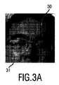
カメラベースのバイタルサイン測定に関して、1つ又は複数の関心領域が、好ましくは測定の前に、皮膚領域において、例えば、額又は頬において、(手動で又は自動的に)選択される。2つのROIが、図3に示される。 For camera-based vital sign measurements, one or more regions of interest are selected (manually or automatically), preferably in the skin region, for example in the forehead or cheek, prior to the measurement. Two ROIs are shown in FIG.
ある実施形態では、測定開始の前に、照明ユニットが自動的に構成される。例えば、個別の照明要素及びそれらの組合せは、シーケンシャルに(異なるレベルで)スイッチオンにされ、オフにされる。異なる照明設定で取得された画像はプロセッサによりその後分析され、最適な照明設定が、撮像データ(受信された光から生成される入力信号)及び/又は得られたバイタルサイン情報の分析に基づき、選択及び調整される。 In an embodiment, the lighting unit is automatically configured before starting the measurement. For example, individual lighting elements and combinations thereof are switched on and off sequentially (at different levels). Images acquired with different lighting settings are then analyzed by the processor and the optimal lighting setting is selected based on analysis of imaging data (input signal generated from received light) and / or vital sign information obtained And adjusted.
ある実施形態において、ROIにおける鏡面反射が、基準の1つとして使用される。即ち、ROIにおける反射を生じさせない又はほとんど生じさせない照明が選択される。反射は、一般に既知のビデオ解析アルゴリズムで検出されることができる。 In some embodiments, specular reflection at the ROI is used as one of the criteria. That is, illumination is selected that causes little or no reflection at the ROI. Reflections can generally be detected with known video analysis algorithms.
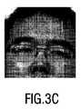
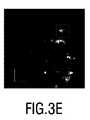
図3A〜図3Cは、3つの異なる照明設定で得られる同じ対象物の顔画像を示し、図3D〜図3Fは、これらの画像において検出される対応する反射を示す。2つの例示的なROIがここで考慮される。明らかに、右上のROI30が使用される場合、図3A及び3Dを得るのに使用する照明設定が選択され、左下のROI31が使用される場合、図3B及び3Eを得るのに使用する照明設定が選択される。 3A-3C show face images of the same object obtained with three different illumination settings, and FIGS. 3D-3F show the corresponding reflections detected in these images. Two exemplary ROIs are considered here. Obviously, if the upper
例えばROIにおける照明の均一性、すべての重要なチャネル(波長)において良好な/安定な照明、及び/又はROIにおいて陰影がないことといった他の要素が、基準において考慮されることもできる。 Other factors can also be considered in the criteria such as illumination uniformity in the ROI, good / stable illumination in all important channels (wavelengths), and / or no shading in the ROI.
撮像品質の他に、ROIから得られたバイタルサイン情報(例えばPPG信号又はSp02信号)の特性又は品質は、照明、例えば合理的な心拍(例えば、30〜250bpm)、酸素飽和(すべてのケースにおいて50〜100%のSp02、ケースの99%において95〜100%)、PPG信号の拍動性振幅、パルス形状及び/又は周期性を選択及び調整する基準として使用されることもできる。 In addition to imaging quality, the characteristics or quality of vital sign information (eg PPG or Sp02 signal) obtained from the ROI can be attributed to illumination, eg reasonable heart rate (eg 30-250 bpm), oxygen saturation (in all cases) 50-100% Sp02, 95-100% in 99% of cases), can also be used as a basis for selecting and adjusting the pulsatile amplitude, pulse shape and / or periodicity of the PPG signal.
照明自己構成プロセスの(ユーザに対する)乱れ及び時間を減らすため、異なる位置に及び/又は異なる角度で配置される複数のカメラが、ある実施形態において使用される。1つの照明に対して、異なるカメラの取得された画像が分析される。これらのカメラのいずれかが最適照明を得る場合、カメラ(及び照明)が測定のために使用される。複数のカメラを用いると、最適照明を見つけることはより容易で高速である。 To reduce perturbations and time (to the user) of the lighting self-configuration process, multiple cameras located at different locations and / or at different angles are used in certain embodiments. For one illumination, acquired images from different cameras are analyzed. If either of these cameras obtains optimal illumination, the camera (and illumination) is used for measurement. With multiple cameras, finding the optimal illumination is easier and faster.
環境、生体及び/又は測定構成における変化後(例えば、ROIを再選択する、対象物が移動する)、照明及びカメラが評価されることができ、必要に応じて、再調整又は再選択される。 After changes in the environment, living body and / or measurement configuration (eg, reselect ROI, object moves), lighting and camera can be evaluated and reconditioned or reselected as needed .
以下に、本発明の用途の別の分野が説明される。 In the following, another field of application of the invention will be described.
未熟児は、産まれてくる準備が整う前に子宮における被保護環境を去る。かれらは、多くの領域において準備ができていない。新生児集中治療室(NICU)は、早産児に対する特別な支援をケアするが、まだ多くの不利な点に苦しむ。集中治療は、乳児に対して邪魔となり、健康に過ごす及び成熟するのに負のインパクトを与える器具を用いて、ある態様で多くのタスクを実行しなければならない。この場合、胎児が母の子宮で経験するものに近いものは、何もない。 Premature babies leave the protected environment in the uterus before they are ready to be born. They are not ready in many areas. The Neonatal Intensive Care Unit (NICU) cares for special support for preterm infants, but still suffers from a number of disadvantages. Intensive care must perform a number of tasks in some manner, using instruments that can interfere with infants and have a negative impact on health and maturity. In this case, nothing is similar to what the fetus experiences in the mother's womb.
例は、バイタルサインを監視する必要があり、虚弱な乳児の皮膚に電極又はセンサを刺す必要があることである。その部分を変更する必要があるとき、皮膚はしばしばはがされる。これらの非常に幼い児童のサイズと比較すると、すべてのこれらの感知部分は通常扱いにくい。この部分は、十分な睡眠を防止又は中断する。成熟した市場でのNICUにおける現在の実行は、例えばCarole Kenner、Jacqueline M McGrathによる「Developmental Care of Newborns and Infants, A Guide for Health Professionals」、National Association of Neonatal Nurses、2010に表されるように、いわゆる発達看護に従うことである。 An example is the need to monitor vital signs and the need to stab electrodes or sensors in the weak infant's skin. When the part needs to be changed, the skin is often peeled off. Compared to the size of these very young children, all these sensitive parts are usually cumbersome. This part prevents or interrupts sufficient sleep. The current implementation of NICU in mature markets is the so-called “Developmental Care of Newborns and Infants, A Guide for Health Professionals” by Carole Kenner, Jacqueline M McGrath, National Association of Neonatal Nurses, 2010, for example. Follow developmental nursing.
本発明は、この努力を支援するために用いられることができる。更に、本発明は、乳児を過剰な光から及び皮膚に適用されるセンサから保護し、未熟児を外界から保護しつつ、カメラを通して親との接触を改善するのを助けることができる。本発明は、カメラの使用を今日実際的に使用不可能にする大きな器材の課題を解決することもできる。 The present invention can be used to support this effort. In addition, the present invention can protect infants from excessive light and from sensors applied to the skin, helping to improve parent contact through the camera while protecting premature infants from the outside world. The present invention also solves the problem of large equipment that makes the use of cameras practically unusable today.
以下、(例えばカメラの形の)検出ユニット及び照明ユニットが、NICU環境にどのように最適に一体化されることができるかについて、本発明のさまざまな実施形態が説明される。一般に、特に斯かる環境において、カメラの使用は、乳児のバイタルサインの監視、親子のボンディング及び遠隔看護を含むさまざまな目的のため機能することができる。 In the following, various embodiments of the present invention will be described how a detection unit (eg in the form of a camera) and a lighting unit can be optimally integrated into the NICU environment. In general, particularly in such an environment, the use of a camera can function for a variety of purposes including infant vital signs monitoring, parent-child bonding and telenursing.
上述したように、未熟児は、あまりに多くの光から保護されることを必要とする。胎児に関する理想的な位置は、外側からの光がごくわずかな存在しない母の子宮である。さらに、未熟児は、その生命及び成長を支援するために、多くの看護、処置及び手順を必要とする。一体化されたライトを持つカメラが、乳児の近くに最適に取り付けられ、これは、できるだけ子宮環境を模倣するのを助けることができる。カメラは、介護者及び両親に対して乳児とインターフェースすることを助けることができる。こうして、
i)乳児の視覚的な確認のため、目を見る、運動を見るために、
ii)カバーされた状態を保ちつつ、両親を乳児に見せるために、及び
iii)乳児のバイタルサインを監視するために、専用及び最小の照明が使用されることができる。As mentioned above, premature babies need to be protected from too much light. The ideal location for the fetus is the mother's uterus, where there is very little light from the outside. In addition, premature babies require a number of nursing care, procedures and procedures to support their life and growth. A camera with integrated light is optimally mounted near the infant, which can help mimic the uterine environment as much as possible. The camera can help interface the infant with caregivers and parents. Thus,
i) For visual confirmation of infants, to see their eyes, see their movements,
Dedicated and minimal lighting can be used to ii) show parents to the infant while remaining covered, and iii) monitor the baby's vital signs.
バイタルサイン監視は、乳児上にいくつかのレベルの光を必要とする。NICUにおいてルームライトの量及び品質は、明確でもなく、一定でもない。乳児が眠る多くの時間がある。減光ライトは、最良の発達看護を提供するためにマストである。これはしばしば、保育器を毛布でカバーし、ルームライトのスイッチを切ることにより実現される。これは、光源レベルが検出ユニット(例えばカメラのビデオセンサ)に関して不適当になり、信号対ノイズレベルが、許容できないほど低くなる状況をもたらす場合がある。受信された光(例えばビデオ画像)の品質は、視聴又は更なる処理にはあまりに適さないものとなる。即ち、それはその意図された目的に関して役に立たなくなる。また、照明の波長分布は、カメラ(監視)目的には適していない場合もある。 Vital sign monitoring requires several levels of light on the infant. In NICU, the amount and quality of room lights is neither clear nor constant. There is a lot of time for infants to sleep. The dimming light is a mast to provide the best developmental nursing. This is often accomplished by covering the incubator with a blanket and switching off the room light. This can lead to situations where the light source level becomes inadequate with respect to the detection unit (eg camera video sensor) and the signal to noise level is unacceptably low. The quality of the received light (eg video image) will be too unsuitable for viewing or further processing. It becomes useless for its intended purpose. Also, the illumination wavelength distribution may not be suitable for camera (monitoring) purposes.
好ましくは検出ユニット(例えばカメラ)においてレベル制御照明ユニット(例えば光源)が提案され、このユニットは、その目的に必要な波長で適切な強度を提供し、同時に、それをできるだけ低く保つことにより、乳児を不必要に不快にしない。 A level-controlled illumination unit (eg a light source) is preferably proposed in the detection unit (eg camera), which provides the appropriate intensity at the wavelength required for that purpose, while at the same time keeping it as low as possible. Do not unnecessarily uncomfortable.
図4は、本発明による生体のバイタルサイン情報を得るデバイス1cの第3の実施形態の概略図を示す。本実施形態において、照明を含む一体化されたカメラフロントエンド40が使用される。これは、入力信号5及び制御信号12を送信する信号回線を含むケーブル13を介して、プロセッサ6及びコントローラ10に接続される。 FIG. 4 shows a schematic view of a third embodiment of a
一体化されたカメラフロントエンド40は、フロントエンドハウジング41、カメラレンズ42(この後に、カメラ(図示省略)が、ハウジング内部に構成される)、複数の照明LED43、及び保育器又は他のデバイスに対して一体化されたカメラフロントエンド40を付ける柔らかい吸着カップリングを有する。 The integrated camera
別の実施形態では、カメラに近い点光源が、画像における陰影を回避するため、及びカメラ及び光源の撮像野の位置を小さく保つために用いられる。さらに別の実施形態において、光源は、影を生み出し、光を遮断する機会を最小化するために、領域において大きくされ、拡散される。 In another embodiment, a point light source close to the camera is used to avoid shading in the image and to keep the position of the camera and light source imaging field small. In yet another embodiment, the light source is enlarged and diffused in the area to create a shadow and minimize the chance of blocking the light.
光源レベルは、1つ又は複数の波長範囲で画像強度を用いてプロセッサ6のフィードバックにより制御されることができる。典型的なスタジオセットアップにおいて最善の画像を得るために光源レベルは最大化されるが、斯かる用途において、発展ニーズに適合するよう、及び子宮における薄暗い環境を模倣するために、未熟児に最小限の光源レベルを使用することが望ましい。最小は、カメラ使用の目的に特有である。こうして、例えば、(未熟児又は少なくとも乳児の顔を有する)監視領域における光源レベルが監視されて、照明ユニットの光源レベルを制御するために用いられる。 The light source level can be controlled by processor 6 feedback using image intensity in one or more wavelength ranges. The light level is maximized to obtain the best image in a typical studio setup, but in such applications it is minimal for premature babies to meet development needs and to mimic the dim environment in the uterus. It is desirable to use different light source levels. The minimum is specific to the purpose of the camera use. Thus, for example, the light level in the monitoring area (having premature babies or at least the infant's face) is monitored and used to control the light level of the lighting unit.
更に、光の色(波長)は目的に対して調整されることができ、それは人間の目に対して最少の視覚的な感度を持つよう選択されることができる。例えば、胸部の運動が主な関心である呼吸監視にカメラが使用される場合、赤又は近赤外線が好ましくは使用される。 Furthermore, the color (wavelength) of the light can be adjusted for the purpose, which can be selected to have minimal visual sensitivity to the human eye. For example, if the camera is used for respiratory monitoring where chest motion is the primary concern, red or near infrared is preferably used.
図4に示されるように、照明ユニットは、監視目的の必要性に基づき選択される波長を備える、一セットのLEDにより実現される。パルス監視に関して、皮膚色における変化が使用される場合、緑の範囲(例えば500nm)におけるLED及び赤い範囲(例えば650nm)における参照が必要とされる。カメラが皮膚を介してビリルビンレベルを測定するのに使用される場合、算出を行うために、複数の波長がカバーされる必要がある(例えば460nm、520nm、650nm)。 As shown in FIG. 4, the lighting unit is realized by a set of LEDs with wavelengths that are selected based on the need for monitoring purposes. For pulse monitoring, if a change in skin color is used, an LED in the green range (eg 500 nm) and a reference in the red range (eg 650 nm) are required. If the camera is used to measure bilirubin levels through the skin, multiple wavelengths need to be covered (eg 460 nm, 520 nm, 650 nm) in order to make the calculation.
この実施形態において、照明要素43(例えばLED又はライト)は、リング照明としてカメラ周りで円形に構成される。好ましくは、照明円錐は、最善のエネルギー使用のためカメラの撮像野にマッチし、近くの類似するシステムとの光干渉だけでなく、介護者及び患者に対する反射及び閃光を回避する。 In this embodiment, the lighting elements 43 (eg LEDs or lights) are configured in a circle around the camera as ring lighting. Preferably, the illumination cone matches the camera field for best energy use and avoids light interference with nearby similar systems as well as reflections and flashes to the caregiver and patient.
広拡散ライトが使用される別のアプローチにおいて、乳児を囲む白熱した表面が使用される。これは、拡散器を含む蛍光バルブといった任意の種類の従来の空間的な拡散光源又はより大きい表面にわたり光を放出する固有の特性を持つより新規なOLED技術により実現されることができる。それらは、保育器キャノピーの透過側面及び上部壁に埋められることができる。 In another approach where a wide diffuse light is used, an incandescent surface surrounding the infant is used. This can be achieved by any kind of conventional spatial diffuse light source, such as a fluorescent bulb containing a diffuser, or newer OLED technology with the unique property of emitting light over a larger surface. They can be buried in the transmission side and top wall of the incubator canopy.
カメラフロントエンド41は好ましくは、NICU看護において起こりそうな任意の状況が原因では、カメラ表示の遮蔽が起こらない態様において取り付けられる。監視対象、例えば顔といった関心ボディパーツが、良く見える位置にあり、意図されるカメラの機能に影響を与えることなく、赤ちゃんの眠りを保護するよう、外部のルームライトが遮蔽されることで、良好な位置が規定される。 The camera
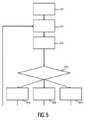
異なる照明要素43(例えばLED)の出力は、信号対ノイズ比及び最少ベビー照明強度の間の最適なトレードオフを実現するよう独立して制御されることができる。対応する方法のフローチャートが、図5に示される。第1のステップS10において、最初のLED出力レベルがセットされる。第2のステップS12において、(入力信号として)生の画像が取られる。第3のステップS14において、この画像は、所望の情報(例えば所望のバイタルサイン)を得るために処理される。第4のステップS16において、SNRが許容可能な範囲にあるかがチェックされる。このチェックの結果に基づき、LED出力レベルは、低下される(S18)か、そのままにされる(S20)、又は増加される(S22)。その後、この方法は、ステップS12に戻る。 The output of different lighting elements 43 (eg LEDs) can be independently controlled to achieve an optimal tradeoff between signal to noise ratio and minimum baby lighting intensity. A flow chart of the corresponding method is shown in FIG. In the first step S10, the first LED output level is set. In a second step S12, a raw image is taken (as an input signal). In a third step S14, this image is processed to obtain the desired information (eg the desired vital sign). In a fourth step S16, it is checked whether the SNR is in an acceptable range. Based on the result of this check, the LED output level is lowered (S18), left as it is (S20), or increased (S22). Thereafter, the method returns to step S12.
図6は、本発明によるデバイスを含む保育器50を示す。非常に小さく虚弱な乳児は典型的に、制御された湿度及び温度環境を可能にする斯かる閉じられた保育器50において保たれる。乳児ベッドは、患者に対するアクセスを可能にする穴54及びドアを持つ透過キャノピー51でカバーされる。斯かる保育器に関して、一体化されたカメラフロントエンド52を置く良好な位置は、キャノピー51の上にある。これは、ほとんどの場合平坦な上端を持つ。 FIG. 6 shows an
一体化されたカメラフロントエンド52は、キャノピー51内部又は外部に取り付けられることができる。それを適所に保持するため、それを内部若しくは外部に固定するため、又はそれを十分に重くするため、及び、キャノピー51に対して滑りにくい表面に重力を用いて、外側の適所にとどまるようにするため、吸着カップ53が好ましくは使用される。外側である場合、吸着カップ53又はノンスリップリング(図4を参照すると参照符号44)が、迷光を外側から離して保つある種類の不透明なゴム封止として形成されることができる。光学カメラ及び光表面のキャノピー51に対する近い接触も、塵及び汚染を遠ざける。 The integrated camera
もし何らかの理由で一体化されたカメラフロントエンド52がキャノピー51内部にあることを必要とする場合、例えば光の過剰な吸収を測定することが意図される場合、乳児の上端のコンパートメントの中央でそれを固定する固定態様が必要とされる。それは、乳児に対する透過的ウィンドウを持つコンパートメントのようなカップとすることができる。ウィンドウは、必要とされる全ての波長に対してキャノピーがなされるより透過的であるのに適した物質及び厚みで作られることができる。 If for some reason the integrated camera
親ボンディング又は音監視といったいくつかの用途に関して、一体化されたカメラフロントエンド52にマイクロホンが含まれることができる。この場合、一体化されたカメラフロントエンド52から汚染及び水を遠ざけつつ、音波が進むことを可能にする開口又は音響膜が好ましくは存在する。 For some applications such as parent bonding or sound monitoring, a microphone may be included in the integrated camera
保育器50上又はこの中への直接的な取付けは、より良い機械的な安定性も与える。即ち、別々のアーム又はスタンド上での取付けと比較して、より不確実でない画像を与える。それでもまだ、乳児を外部光から保護するために、介護者は毛布により保育器をカバーすることができる。 Direct mounting on or in the
図7は、本発明によるデバイスを含む放射暖熱装置60を示す。より大きい乳児の場合及びより出産日に近い乳児の場合、乳児はしばしば、調整された温度を保つのを助けるために、斯かる放射暖熱装置60に保たれる。これは、処置、看護及び手順に関して患者に対するより良好なアクセスを与える。しかし、乳児はうまく規定された場所におり、カメラ3は、所定の位置に取り付けられることができる。 FIG. 7 shows a radiant warmer 60 comprising a device according to the invention. In the case of larger babies and babies closer to the birth date, the infant is often kept in such a radiant warmer 60 to help maintain a regulated temperature. This gives better access to the patient regarding treatment, nursing and procedures. However, the infant is in a well-defined location and the camera 3 can be mounted in place.
放射暖熱装置60は通常、乳児2の上で中心化されるIRウオーミングランプ62を持つ。その熱素子62を保持する手段は、スペースが許す限り同じ場所でこの熱素子62と共に一体化されたカメラフロントエンドを一体化するのにそれを理想的な場所にする。熱素子62を搬送するアーム63は内部にカメラ61を搬送することもできる(基本的に見えない。なぜなら、それは、小さい穴だけを必要とするからである)。それは、カメラ61を支持する照明要素64を含むこともできる。ケーブルルーティングは、もしプロセッサ、制御ユニット、並びにカメラパラメータ、制御及び結果に関するディスプレイも放射暖熱装置60に一体化されるのであれば、暖熱装置、特にアーム63内部で完全に管理されることができる。放射暖熱装置60は、モニタリング及び加温機能の間で、ユーザインタフェース及び任意の計算手段を共有することができる。 The radiant warmer 60 typically has an
別々のアームにおける一体化されたカメラフロントエンドにわたるこの構成の利点は、それが、目立たなくて、ほとんど見えなくて、流体の流出による汚染からうまく保護されて、及び器材が少なくケーブル管理が良好なことから、乳児へのより好適なアクセスを提供する点にある。 The advantages of this configuration over an integrated camera front end in separate arms are that it is inconspicuous, almost invisible, well protected from contamination by fluid spills, and has low equipment and good cable management Therefore, it is in providing a more favorable access to the infant.
まとめると、後者の実施形態は、検出された信号の処理からのフィードバックループにより制御された光源レベルを提供し、カメラの目的を最適化して、同時に乳児への妨害が最も少ない専用の波長を提供し、及びカメラ及び照明の一体化によって保育器及び暖熱装置の改良されたワークフローを提供する。 In summary, the latter embodiment provides a light source level controlled by a feedback loop from the processing of the detected signal, optimizing the purpose of the camera and at the same time providing a dedicated wavelength with the least interference to the infant And providing an improved workflow for incubators and heating devices by integrating camera and lighting.
こうして、本発明のこれらの後者の実施形態によれば、看護デバイスが与えられ、このデバイスは、
新生児を搬送するチャイルドキャリアと、
少なくとも関心領域から反射される少なくとも1つの波長間隔における光を受信し、上記受信された光から入力信号を生成する検出器と、
入力信号を処理し、遠隔フォトプレチスモグラフィを用いて上記入力信号から生体のバイタルサイン情報を得るプロセッサと、
少なくとも上記関心領域を光で照射する照明器と、
上記入力信号及び/又は上記得られたバイタルサイン情報に基づき、上記照明ユニットを制御するコントローラとを有する。Thus, according to these latter embodiments of the present invention, a nursing device is provided, the device comprising:
A child carrier that carries the newborn,
A detector for receiving light in at least one wavelength interval reflected from at least the region of interest and generating an input signal from the received light;
A processor that processes the input signal and obtains vital sign information of the living body from the input signal using remote photoplethysmography;
An illuminator that illuminates at least the region of interest with light;
And a controller for controlling the lighting unit based on the input signal and / or the obtained vital sign information.
ある実施形態において、上記看護デバイスは、子供を収容するキャノピーを更に有する保育器であり、上記検出器及び上記照明器は、上記キャノピーに構成される。別の実施形態では、上記看護デバイスは、子供を暖める放射線を放出するラジエータを更に有する放射暖熱装置であり、上記検出器、上記照明器及び上記ラジエータが、上記放射暖熱装置のキャリアに又はこの中に構成される。好ましくは、上記看護デバイスは、新生児のバイタルサイン情報をケアし、及び得る新生児看護デバイスである。 In one embodiment, the nursing device is an incubator further having a canopy that houses a child, and the detector and the illuminator are configured in the canopy. In another embodiment, the nursing device is a radiant heating device further comprising a radiator that emits radiation that warms the child, wherein the detector, the illuminator and the radiator are on a carrier of the radiant heating device or Configured in this. Preferably, the nursing device is a newborn nursing device that cares for and obtains newborn vital sign information.
本発明は、さまざまな用途において適用されることができる。心拍、呼吸レート及びSp02は、監視患者及びホームヘルスケアにおいて非常に重要な要素である。ここで、遠隔心拍監視がますます重要になる。更に、本発明は、フィットネスデバイスにおいて心拍を登録するのに適用されることができる。提案された本発明は、カメラベースのバイタルサイン監視が、変化する制御可能な照明を用いて、又は可変の光状態を用いて実行される任意の分野に適用されることができる。通常、バイタルサイン抽出は、かなりチャレンジングであり、場合によっては不可能であるが、これが正確で信頼性高く実行されることができる。 The present invention can be applied in various applications. Heart rate, respiration rate and Sp02 are very important factors in monitored patients and home health care. Here, remote heart rate monitoring becomes more and more important. Furthermore, the present invention can be applied to register heartbeats in fitness devices. The proposed invention can be applied to any field where camera-based vital sign monitoring is performed with varying controllable illumination or with variable light conditions. Usually, vital sign extraction is quite challenging and in some cases impossible, but this can be performed accurately and reliably.
本発明が図面及び前述の説明において詳細に図示され及び説明されたが、斯かる図示及び説明は、説明的又は例示的であると考えられ、本発明を限定するものではない。本発明は、開示された実施形態に限定されるものではない。図面、開示及び添付された請求項の研究から、開示された実施形態に対する他の変形が、請求項に記載の本発明を実施する当業者により理解され、実行されることができる。 While the invention has been illustrated and described in detail in the drawings and foregoing description, such illustration and description are to be considered illustrative or exemplary and not restrictive. The invention is not limited to the disclosed embodiments. From studying the drawings, disclosure and appended claims, other variations to the disclosed embodiments can be understood and implemented by those skilled in the art practicing the claimed invention.
請求項において、単語「有する」は他の要素又はステップを除外するものではなく、不定冠詞「a」又は「an」は複数性を除外するものではない。単一の要素又は他のユニットが、請求項に記載される複数のアイテムの機能を満たすことができる。特定の手段が相互に異なる従属項に記載されるという単なる事実は、これらの手段の組み合わせが有利に使用されることができないことを意味するものではない。 In the claims, the word “comprising” does not exclude other elements or steps, and the indefinite article “a” or “an” does not exclude a plurality. A single element or other unit may fulfill the functions of several items recited in the claims. The mere fact that certain measures are recited in mutually different dependent claims does not indicate that a combination of these measured cannot be used to advantage.
請求項における任意の参照符号は、発明の範囲を限定するものとして解釈されるべきではない。 Any reference signs in the claims should not be construed as limiting the scope.
Claims (12)
Translated fromJapanese生体の少なくとも関心領域から反射される少なくとも1つの波長間隔における光を受信し、前記受信された光から入力信号を生成する検出ユニットと、
前記入力信号を処理して、遠隔フォトプレチスモグラフィを用いて前記入力信号から前記生体のバイタルサイン情報を得る処理ユニットと、
少なくとも前記関心領域を光で照射する照明ユニットと、
前記入力信号及び/又は前記得られたバイタルサイン情報に基づき、前記照明ユニットを制御する制御ユニットとを有し、
前記制御ユニットが、前記関心領域における鏡面反射の量を決定し、前記鏡面反射の量を減らす又は最小化するよう、前記鏡面反射の決定された量に基づき、前記照明ユニットを制御するよう構成される、デバイス。A device for obtaining vital sign information of a living body,
A detection unit that receives light in at least one wavelength interval reflected from at least a region of interest of a living body and generates an input signal from the received light;
A processing unit that processes the input signal to obtain vital sign information of the living body from the input signal using remote photoplethysmography;
A lighting unit for illuminating at least the region of interest with light;
A control unit for controlling the lighting unit based on the input signal and / or the obtained vital sign information,
The control unit is configured to determine the amount of specular reflection in the region of interest and to control the illumination unit based on the determined amount of specular reflection to reduce or minimize the amount of specular reflection. Device.
前記監視された領域、前記環境及び/又は前記生体の変化が検出される場合、前記制御ユニットは、前記照明ユニットの実際の制御設定をチェックし、前記入力信号及び/又は前記得られたバイタルサイン情報に基づき、前記照明ユニットを再び制御するよう構成される、請求項1に記載のデバイス。The detection unit is configured to detect a monitored region,environment and / or changes in the organism;
If a change in the monitored area, the environment and / or the living body is detected, the control unit checks the actual control settings of the lighting unit and the input signal and / or the obtained vital sign. The device of claim 1, configured to control the lighting unit again based on information.
生体の少なくとも関心領域を光で照射するステップと、
少なくとも前記関心領域から反射される少なくとも1つの波長間隔における光を受信するステップと、
前記受信された光から入力信号を生成するステップと、
前記入力信号を処理し、遠隔フォトプレチスモグラフィを用いて前記入力信号から前記生体のバイタルサイン情報を得るステップと、
前記入力信号及び/又は前記得られたバイタルサイン情報に基づき、前記照射を制御するステップとを有し、
前記制御するステップが、前記関心領域における鏡面反射の量を決定し、前記鏡面反射の量を減らす又は最小化するよう、前記鏡面反射の決定された量に基づき、前記照射を制御することにより行われる、方法。In a method for obtaining vital sign information of a living body,
Irradiating at least a region of interest of a living body with light;
Receiving light in at least one wavelength interval reflected from at least the region of interest;
Generating an input signal from the received light;
Processing the input signal to obtain vital sign information of the living body from the input signal using remote photoplethysmography;
Controlling the irradiation based on the input signal and / or the obtained vital sign information,
The controlling step is performed by determining the amount of specular reflection in the region of interest and controlling the illumination based on the determined amount of specular reflection to reduce or minimize the amount of specular reflection. The method.
Applications Claiming Priority (9)
| Application Number | Priority Date | Filing Date | Title |
|---|---|---|---|
| US201261732985P | 2012-12-04 | 2012-12-04 | |
| EP12195438 | 2012-12-04 | ||
| US61/732,985 | 2012-12-04 | ||
| EP12195438.2 | 2012-12-04 | ||
| US201361781155P | 2013-03-14 | 2013-03-14 | |
| EP13159140 | 2013-03-14 | ||
| EP13159140.6 | 2013-03-14 | ||
| US61/781,155 | 2013-03-14 | ||
| PCT/IB2013/060512WO2014087310A1 (en) | 2012-12-04 | 2013-11-29 | Device and method for obtaining vital sign information of a living being |
Publications (2)
| Publication Number | Publication Date |
|---|---|
| JP2016503327A JP2016503327A (en) | 2016-02-04 |
| JP6054543B2true JP6054543B2 (en) | 2016-12-27 |
Family
ID=50826097
Family Applications (1)
| Application Number | Title | Priority Date | Filing Date |
|---|---|---|---|
| JP2015544599AActiveJP6054543B2 (en) | 2012-12-04 | 2013-11-29 | Device and method for obtaining vital sign information of a living body |
Country Status (10)
| Country | Link |
|---|---|
| US (1) | US10178958B2 (en) |
| EP (1) | EP2928360B1 (en) |
| JP (1) | JP6054543B2 (en) |
| CN (2) | CN109157223A (en) |
| BR (1) | BR112015012718A2 (en) |
| CA (1) | CA2893324A1 (en) |
| IL (1) | IL239135B (en) |
| MX (1) | MX360210B (en) |
| RU (1) | RU2675083C2 (en) |
| WO (1) | WO2014087310A1 (en) |
Families Citing this family (61)
| Publication number | Priority date | Publication date | Assignee | Title |
|---|---|---|---|---|
| US10238292B2 (en)* | 2013-03-15 | 2019-03-26 | Hill-Rom Services, Inc. | Measuring multiple physiological parameters through blind signal processing of video parameters |
| WO2016011420A1 (en)* | 2014-07-17 | 2016-01-21 | University Of Southern California | Methods, compounds, and compositions for the treatment of musculoskeletal diseases |
| US20140323832A1 (en)* | 2013-04-24 | 2014-10-30 | Selvaraj Thangaraj | System and Method for non-invasive measurement of bilirubin in newborn and infants |
| CN105473060B (en)* | 2013-08-06 | 2019-12-03 | 皇家飞利浦有限公司 | System and method for extracting physiologic information from the electromagnetic radiation remotely detected |
| WO2015061793A1 (en)* | 2013-10-25 | 2015-04-30 | The University Of Akron | Multipurpose imaging and display system |
| JP6481130B2 (en)* | 2014-06-25 | 2019-03-13 | Winフロンティア株式会社 | Excitement degree detection device, excitement degree detection system, excitement degree detection server device, excitement degree detection device program, excitement degree detection server device program |
| GB2528044B (en)* | 2014-07-04 | 2018-08-22 | Arc Devices Ni Ltd | Non-touch optical detection of vital signs |
| FR3023699B1 (en)* | 2014-07-21 | 2016-09-02 | Withings | METHOD AND DEVICE FOR MONITORING A BABY AND INTERACTING |
| US9854973B2 (en) | 2014-10-25 | 2018-01-02 | ARC Devices, Ltd | Hand-held medical-data capture-device interoperation with electronic medical record systems |
| US9770213B2 (en)* | 2014-10-30 | 2017-09-26 | Koninklijke Philips N.V. | Device, system and method for extracting physiological information |
| EP3225975A4 (en)* | 2014-11-27 | 2017-11-29 | Panasonic Intellectual Property Management Co., Ltd. | Image acquisition device, image formation system, and image formation method |
| US10004408B2 (en) | 2014-12-03 | 2018-06-26 | Rethink Medical, Inc. | Methods and systems for detecting physiology for monitoring cardiac health |
| EP3250108A1 (en)* | 2015-01-30 | 2017-12-06 | Koninklijke Philips N.V. | Photoplethysmography apparatus |
| WO2017025775A1 (en)* | 2015-08-11 | 2017-02-16 | Latvijas Universitate | Device for adaptive photoplethysmography imaging |
| CN108024897B (en)* | 2015-09-15 | 2021-03-09 | 皇家飞利浦有限公司 | Method and apparatus for improved neonatal care |
| US10893814B2 (en)* | 2015-10-06 | 2021-01-19 | Koninklijke Philips N.V. | System and method for obtaining vital sign related information of a living being |
| WO2017060342A1 (en) | 2015-10-06 | 2017-04-13 | Koninklijke Philips N.V. | Device, system and method for obtaining vital sign related information of a living being |
| US10413226B2 (en)* | 2015-11-09 | 2019-09-17 | Arizona Board Of Regents On Behalf Of Arizona State University | Noncontact monitoring of blood oxygen saturation using camera |
| US9615427B1 (en)* | 2015-11-30 | 2017-04-04 | Texas Instruments Incorporated | Exploiting constructive interference from ambient conditions |
| EP3393347B8 (en) | 2015-12-23 | 2020-03-25 | Koninklijke Philips N.V. | Apparatus and method for measuring the quality of an extracted signal |
| WO2017136857A1 (en)* | 2016-02-05 | 2017-08-10 | Mcbain Theodore Dean | System, method and device for confirmation of an operator's health condition and alive status |
| WO2017147493A1 (en) | 2016-02-24 | 2017-08-31 | Incept, Llc | Enhanced flexibility neurovascular catheter |
| CN109074755B (en)* | 2016-04-06 | 2024-06-14 | 皇家飞利浦有限公司 | Methods, devices and systems for enabling analysis of performance of vital sign detectors |
| US10335045B2 (en) | 2016-06-24 | 2019-07-02 | Universita Degli Studi Di Trento | Self-adaptive matrix completion for heart rate estimation from face videos under realistic conditions |
| US10447972B2 (en) | 2016-07-28 | 2019-10-15 | Chigru Innovations (OPC) Private Limited | Infant monitoring system |
| GB2569936B (en)* | 2016-10-14 | 2021-12-01 | Facense Ltd | Calculating respiratory parameters from thermal measurements |
| US20180125380A1 (en)* | 2016-11-10 | 2018-05-10 | Htc Corporation | Method for detecting heart rate and heart rate monitoring device using the same |
| JP7264581B2 (en) | 2017-01-06 | 2023-04-25 | インセプト、リミテッド、ライアビリティ、カンパニー | Antithrombotic coating for aneurysm treatment devices |
| US10506926B2 (en) | 2017-02-18 | 2019-12-17 | Arc Devices Limited | Multi-vital sign detector in an electronic medical records system |
| US10492684B2 (en) | 2017-02-21 | 2019-12-03 | Arc Devices Limited | Multi-vital-sign smartphone system in an electronic medical records system |
| EP3375351A1 (en) | 2017-03-13 | 2018-09-19 | Koninklijke Philips N.V. | Device, system and method for measuring and processing physiological signals of a subject |
| WO2018172626A1 (en)* | 2017-03-24 | 2018-09-27 | Rdi | Audiovisual communication system |
| US10602987B2 (en) | 2017-08-10 | 2020-03-31 | Arc Devices Limited | Multi-vital-sign smartphone system in an electronic medical records system |
| EP3501388A1 (en)* | 2017-12-22 | 2019-06-26 | Biospectal SA | Optical blood pressure measurement method and system |
| JP7133771B2 (en)* | 2018-02-13 | 2022-09-09 | パナソニックIpマネジメント株式会社 | Biological information display device, biological information display method, and biological information display program |
| CN110236509A (en)* | 2018-03-07 | 2019-09-17 | 台北科技大学 | Method for real-time analysis of physiological characteristics in video |
| US11395665B2 (en) | 2018-05-01 | 2022-07-26 | Incept, Llc | Devices and methods for removing obstructive material, from an intravascular site |
| AU2019262972B2 (en) | 2018-05-01 | 2025-02-27 | Incept, Llc | Devices and methods for removing obstructive material from an intravascular site |
| US10485431B1 (en) | 2018-05-21 | 2019-11-26 | ARC Devices Ltd. | Glucose multi-vital-sign system in an electronic medical records system |
| IL266849A (en)* | 2018-06-07 | 2019-08-29 | Continuse Biometrics Ltd | System and method for use in photoplethysmography |
| EP3581092A1 (en)* | 2018-06-12 | 2019-12-18 | Koninklijke Philips N.V. | System and method for determining at least one vital sign of a subject |
| US11510584B2 (en)* | 2018-06-15 | 2022-11-29 | Covidien Lp | Systems and methods for video-based patient monitoring during surgery |
| US11471582B2 (en) | 2018-07-06 | 2022-10-18 | Incept, Llc | Vacuum transfer tool for extendable catheter |
| US11517335B2 (en) | 2018-07-06 | 2022-12-06 | Incept, Llc | Sealed neurovascular extendable catheter |
| US11766539B2 (en) | 2019-03-29 | 2023-09-26 | Incept, Llc | Enhanced flexibility neurovascular catheter |
| EP3798620A1 (en)* | 2019-09-25 | 2021-03-31 | ETA SA Manufacture Horlogère Suisse | System and method for managing lighting of an area of interest comprising at least one object capable of being handled by a user |
| US11134859B2 (en) | 2019-10-15 | 2021-10-05 | Imperative Care, Inc. | Systems and methods for multivariate stroke detection |
| US12232869B2 (en)* | 2019-10-18 | 2025-02-25 | Viavi Solutions Inc. | Sensor device |
| EP4076611A4 (en) | 2019-12-18 | 2023-11-15 | Imperative Care, Inc. | Methods and systems for treating venous thromboembolic disease |
| US20210316127A1 (en) | 2019-12-18 | 2021-10-14 | Imperative Care, Inc. | Hemostasis valve |
| US11638637B2 (en) | 2019-12-18 | 2023-05-02 | Imperative Care, Inc. | Method of removing embolic material with thrombus engagement tool |
| JP7325651B2 (en)* | 2020-02-17 | 2023-08-14 | コーニンクレッカ フィリップス エヌ ヴェ | System to ensure health safety when charging wearable health |
| CN113747934B (en) | 2020-03-10 | 2024-07-09 | 因普瑞缇夫护理公司 | Enhanced flexibility neurovascular catheter |
| WO2021247300A1 (en) | 2020-06-01 | 2021-12-09 | Arc Devices Limited | Apparatus and methods for measuring blood pressure and other vital signs via a finger |
| US11207497B1 (en) | 2020-08-11 | 2021-12-28 | Imperative Care, Inc. | Catheter with enhanced tensile strength |
| US12279857B2 (en) | 2021-04-01 | 2025-04-22 | Hill-Rom Services, Inc. | Video used to estimate vital signs |
| US20230052862A1 (en) | 2021-08-12 | 2023-02-16 | Imperative Care, Inc. | Sterile packaging assembly for robotic interventional device |
| USD1077996S1 (en) | 2021-10-18 | 2025-06-03 | Imperative Care, Inc. | Inline fluid filter |
| WO2024178376A1 (en)* | 2023-02-24 | 2024-08-29 | Arthur Wallace | Audio visual detection platform for patient monitoring |
| PL445270A1 (en)* | 2023-06-20 | 2024-12-23 | Akademia Górniczo-Hutnicza Im.Stanisława Staszica W Krakowie | Adaptive selective lighting system for optical detection of vital signs |
| PL445269A1 (en)* | 2023-06-20 | 2024-12-23 | Akademia Górniczo-Hutnicza im. Stanisława Staszica w Krakowie | Adaptive selective lighting method for optical detection of vital signs |
Family Cites Families (19)
| Publication number | Priority date | Publication date | Assignee | Title |
|---|---|---|---|---|
| US5140990A (en)* | 1990-09-06 | 1992-08-25 | Spacelabs, Inc. | Method of measuring blood pressure with a photoplethysmograph |
| NL1012943C2 (en) | 1999-08-31 | 2001-03-01 | Tno | Detector and imaging device for determining concentration ratios. |
| US6409654B1 (en) | 2000-08-15 | 2002-06-25 | Mcclain Anthony | Incubator system with monitoring and communicating capabilities |
| EP1357879B1 (en) | 2001-02-06 | 2008-12-24 | Draeger Medical Systems, Inc. | Infant incubator with non-contact sensing and monitoring |
| CN100349542C (en)* | 2004-05-29 | 2007-11-21 | 倪蔚民 | Real time automatic non-invasion iris optical imaging device |
| GB0607270D0 (en)* | 2006-04-11 | 2006-05-17 | Univ Nottingham | The pulsing blood supply |
| WO2007144880A2 (en)* | 2006-06-13 | 2007-12-21 | Elfi-Tech Ltd. | System and method for measurement of biological parameters of a subject |
| RU2354290C1 (en)* | 2007-07-11 | 2009-05-10 | Закрытое акционерное общество "ОКБ "РИТМ" | Photoplethysmograph |
| WO2009040711A2 (en)* | 2007-09-25 | 2009-04-02 | Koninklijke Philips Electronics N.V. | Method and system for monitoring vital body signs of a seated person |
| WO2009073396A1 (en) | 2007-12-04 | 2009-06-11 | Draeger Medical Systems Inc. | Warming therapy device including camera and phototherapy devices |
| JP5559776B2 (en)* | 2008-06-16 | 2014-07-23 | コーニンクレッカ フィリップス エヌ ヴェ | Monitoring patient vital parameters using "IN-SITU" modulation scheme to avoid interference |
| EP2485636A4 (en) | 2009-10-09 | 2013-07-03 | Univ Maryland | NON-INVASIVE DETECTION SYSTEM OF REMOTE PARAMETER AND ASSOCIATED METHOD |
| RU90325U1 (en) | 2009-10-19 | 2010-01-10 | Федеральное государственное унитарное предприятие "Производственное объединение "Уральский оптико-механический завод" имени Э.С. Яламова" (ФГУП "ПО "УОМЗ") | INCUBATOR FOR NEWBORNS |
| LV14514B (en)* | 2010-10-06 | 2012-08-20 | Latvijas Universitāte | Equipment and method for optical contactless control of heart rate parameters |
| DE102010056615A1 (en) | 2010-12-30 | 2012-07-05 | Vladimir Blazek | Opto-electronic, camera-based device for noninvasive, noncontact and spatially resolved detection of vital signs of child, has video camera that is located outside of incubator and is directed at selected skin area of body |
| WO2012093358A1 (en)* | 2011-01-05 | 2012-07-12 | Koninklijke Philips Electronics N.V. | Device and method for extracting information from characteristic signals |
| BR112013026623A2 (en)* | 2011-04-21 | 2016-12-27 | Koninkl Philips Nv | device and method for measuring an individual's vital signs and computer program |
| CN202437546U (en) | 2012-01-07 | 2012-09-19 | 南阳医学高等专科学校第一附属医院 | Online monitored newborn incubator |
| RU2649529C2 (en)* | 2012-10-23 | 2018-04-03 | Конинклейке Филипс Н.В. | Device and method for obtaining vital sign information of a living being |
- 2013
- 2013-11-29CACA2893324Apatent/CA2893324A1/ennot_activeAbandoned
- 2013-11-29EPEP13820971.3Apatent/EP2928360B1/enactiveActive
- 2013-11-29WOPCT/IB2013/060512patent/WO2014087310A1/enactiveApplication Filing
- 2013-11-29CNCN201810857011.XApatent/CN109157223A/enactivePending
- 2013-11-29MXMX2015006918Apatent/MX360210B/enactiveIP Right Grant
- 2013-11-29BRBR112015012718Apatent/BR112015012718A2/ennot_activeApplication Discontinuation
- 2013-11-29CNCN201380057772.2Apatent/CN104768452A/enactivePending
- 2013-11-29RURU2015126594Apatent/RU2675083C2/ennot_activeIP Right Cessation
- 2013-11-29JPJP2015544599Apatent/JP6054543B2/enactiveActive
- 2013-12-02USUS14/093,566patent/US10178958B2/enactiveActive
- 2015
- 2015-06-02ILIL239135Apatent/IL239135B/ennot_activeIP Right Cessation
Also Published As
| Publication number | Publication date |
|---|---|
| US20140155759A1 (en) | 2014-06-05 |
| CN104768452A (en) | 2015-07-08 |
| MX360210B (en) | 2018-10-24 |
| MX2015006918A (en) | 2015-09-16 |
| EP2928360B1 (en) | 2017-01-11 |
| EP2928360A1 (en) | 2015-10-14 |
| IL239135A0 (en) | 2015-07-30 |
| WO2014087310A1 (en) | 2014-06-12 |
| RU2675083C2 (en) | 2018-12-14 |
| BR112015012718A2 (en) | 2017-07-11 |
| CA2893324A1 (en) | 2014-06-12 |
| JP2016503327A (en) | 2016-02-04 |
| IL239135B (en) | 2018-11-29 |
| CN109157223A (en) | 2019-01-08 |
| US10178958B2 (en) | 2019-01-15 |
| RU2015126594A (en) | 2017-01-13 |
Similar Documents
| Publication | Publication Date | Title |
|---|---|---|
| JP6054543B2 (en) | Device and method for obtaining vital sign information of a living body | |
| US10893814B2 (en) | System and method for obtaining vital sign related information of a living being | |
| US9999355B2 (en) | Device, system and method for determining vital signs of a subject based on reflected and transmitted light | |
| JP6449271B2 (en) | System for screening oxygenation status of subjects | |
| US11272142B2 (en) | System and method for determining vital sign information | |
| US9770213B2 (en) | Device, system and method for extracting physiological information | |
| JP6437563B2 (en) | Device, system and method for determining a vital sign of an object based on reflected and transmitted light | |
| EP3007620B1 (en) | System and method for monitoring light and sound impact on a person | |
| US20170014087A1 (en) | Device, system and method for determining vital signs of a subject | |
| JP6854284B2 (en) | Devices, systems and methods for obtaining vital signs related information of living organisms | |
| JP6682605B2 (en) | Device and method for determining a vital sign of an object based on reflected and transmitted light |
Legal Events
| Date | Code | Title | Description |
|---|---|---|---|
| A621 | Written request for application examination | Free format text:JAPANESE INTERMEDIATE CODE: A621 Effective date:20150602 | |
| A871 | Explanation of circumstances concerning accelerated examination | Free format text:JAPANESE INTERMEDIATE CODE: A871 Effective date:20150602 | |
| A975 | Report on accelerated examination | Free format text:JAPANESE INTERMEDIATE CODE: A971005 Effective date:20151130 | |
| A131 | Notification of reasons for refusal | Free format text:JAPANESE INTERMEDIATE CODE: A131 Effective date:20151203 | |
| A521 | Request for written amendment filed | Free format text:JAPANESE INTERMEDIATE CODE: A523 Effective date:20160225 | |
| A131 | Notification of reasons for refusal | Free format text:JAPANESE INTERMEDIATE CODE: A131 Effective date:20160510 | |
| A521 | Request for written amendment filed | Free format text:JAPANESE INTERMEDIATE CODE: A523 Effective date:20160713 | |
| A131 | Notification of reasons for refusal | Free format text:JAPANESE INTERMEDIATE CODE: A131 Effective date:20160906 | |
| A521 | Request for written amendment filed | Free format text:JAPANESE INTERMEDIATE CODE: A523 Effective date:20160914 | |
| TRDD | Decision of grant or rejection written | ||
| A01 | Written decision to grant a patent or to grant a registration (utility model) | Free format text:JAPANESE INTERMEDIATE CODE: A01 Effective date:20161108 | |
| A61 | First payment of annual fees (during grant procedure) | Free format text:JAPANESE INTERMEDIATE CODE: A61 Effective date:20161130 | |
| R150 | Certificate of patent or registration of utility model | Ref document number:6054543 Country of ref document:JP Free format text:JAPANESE INTERMEDIATE CODE: R150 | |
| R250 | Receipt of annual fees | Free format text:JAPANESE INTERMEDIATE CODE: R250 | |
| R250 | Receipt of annual fees | Free format text:JAPANESE INTERMEDIATE CODE: R250 | |
| R250 | Receipt of annual fees | Free format text:JAPANESE INTERMEDIATE CODE: R250 | |
| R250 | Receipt of annual fees | Free format text:JAPANESE INTERMEDIATE CODE: R250 | |
| R250 | Receipt of annual fees | Free format text:JAPANESE INTERMEDIATE CODE: R250 | |
| R250 | Receipt of annual fees | Free format text:JAPANESE INTERMEDIATE CODE: R250 |