JP6050819B2 - Pressure reduction system and method using leak detection member - Google Patents
Pressure reduction system and method using leak detection memberDownload PDFInfo
- Publication number
- JP6050819B2 JP6050819B2JP2014530668AJP2014530668AJP6050819B2JP 6050819 B2JP6050819 B2JP 6050819B2JP 2014530668 AJP2014530668 AJP 2014530668AJP 2014530668 AJP2014530668 AJP 2014530668AJP 6050819 B2JP6050819 B2JP 6050819B2
- Authority
- JP
- Japan
- Prior art keywords
- distribution manifold
- detection
- exposed
- seal member
- tissue site
- Prior art date
- Legal status (The legal status is an assumption and is not a legal conclusion. Google has not performed a legal analysis and makes no representation as to the accuracy of the status listed.)
- Expired - Fee Related
Links
- 238000001514detection methodMethods0.000titleclaimsdescription115
- 238000000034methodMethods0.000titleclaimsdescription19
- 238000009826distributionMethods0.000claimsdescription92
- 210000001519tissueAnatomy0.000claimsdescription89
- 239000000463materialSubstances0.000claimsdescription72
- 239000007789gasSubstances0.000claimsdescription25
- 210000002615epidermisAnatomy0.000claimsdescription21
- CURLTUGMZLYLDI-UHFFFAOYSA-NCarbon dioxideChemical compoundO=C=OCURLTUGMZLYLDI-UHFFFAOYSA-N0.000claimsdescription18
- QVGXLLKOCUKJST-UHFFFAOYSA-Natomic oxygenChemical compound[O]QVGXLLKOCUKJST-UHFFFAOYSA-N0.000claimsdescription15
- 229910052760oxygenInorganic materials0.000claimsdescription15
- 239000001301oxygenSubstances0.000claimsdescription15
- PEDCQBHIVMGVHV-UHFFFAOYSA-NGlycerineChemical compoundOCC(O)COPEDCQBHIVMGVHV-UHFFFAOYSA-N0.000claimsdescription12
- 239000001569carbon dioxideSubstances0.000claimsdescription9
- 229910002092carbon dioxideInorganic materials0.000claimsdescription9
- GWEVSGVZZGPLCZ-UHFFFAOYSA-NTitan oxideChemical compoundO=[Ti]=OGWEVSGVZZGPLCZ-UHFFFAOYSA-N0.000claimsdescription8
- 229960000907methylthioninium chlorideDrugs0.000claimsdescription5
- FRPHFZCDPYBUAU-UHFFFAOYSA-NBromocresolgreenChemical compoundCC1=C(Br)C(O)=C(Br)C=C1C1(C=2C(=C(Br)C(O)=C(Br)C=2)C)C2=CC=CC=C2S(=O)(=O)O1FRPHFZCDPYBUAU-UHFFFAOYSA-N0.000claimsdescription4
- 239000004408titanium dioxideSubstances0.000claimsdescription4
- 230000008878couplingEffects0.000claimsdescription3
- 238000010168coupling processMethods0.000claimsdescription3
- 238000005859coupling reactionMethods0.000claimsdescription3
- 238000005507sprayingMethods0.000claimsdescription3
- -1azolithamineChemical compound0.000claimsdescription2
- XJRPTMORGOIMMI-UHFFFAOYSA-Nethyl 2-amino-4-(trifluoromethyl)-1,3-thiazole-5-carboxylateChemical compoundCCOC(=O)C=1SC(N)=NC=1C(F)(F)FXJRPTMORGOIMMI-UHFFFAOYSA-N0.000claimsdescription2
- ZWJINEZUASEZBH-UHFFFAOYSA-Nfenamic acidChemical compoundOC(=O)C1=CC=CC=C1NC1=CC=CC=C1ZWJINEZUASEZBH-UHFFFAOYSA-N0.000claimsdescription2
- 238000004519manufacturing processMethods0.000claimsdescription2
- CEQFOVLGLXCDCX-WUKNDPDISA-Nmethyl redChemical compoundC1=CC(N(C)C)=CC=C1\N=N\C1=CC=CC=C1C(O)=OCEQFOVLGLXCDCX-WUKNDPDISA-N0.000claimsdescription2
- 239000011540sensing materialSubstances0.000claimsdescription2
- RBTBFTRPCNLSDE-UHFFFAOYSA-N3,7-bis(dimethylamino)phenothiazin-5-iumChemical compoundC1=CC(N(C)C)=CC2=[S+]C3=CC(N(C)C)=CC=C3N=C21RBTBFTRPCNLSDE-UHFFFAOYSA-N0.000claims1
- 210000003491skinAnatomy0.000description26
- 238000002360preparation methodMethods0.000description22
- 239000003795chemical substances by applicationSubstances0.000description18
- 239000000853adhesiveSubstances0.000description14
- 230000001070adhesive effectEffects0.000description14
- 239000012530fluidSubstances0.000description12
- 239000007788liquidSubstances0.000description12
- 238000007789sealingMethods0.000description11
- 210000000416exudates and transudateAnatomy0.000description8
- 239000006260foamSubstances0.000description8
- 239000013543active substanceSubstances0.000description7
- 230000002745absorbentEffects0.000description5
- 239000002250absorbentSubstances0.000description5
- 230000008901benefitEffects0.000description5
- 230000006837decompressionEffects0.000description5
- 239000000975dyeSubstances0.000description5
- 230000010261cell growthEffects0.000description4
- CXKWCBBOMKCUKX-UHFFFAOYSA-Mmethylene blueChemical compound[Cl-].C1=CC(N(C)C)=CC2=[S+]C3=CC(N(C)C)=CC=C3N=C21CXKWCBBOMKCUKX-UHFFFAOYSA-M0.000description4
- QGZKDVFQNNGYKY-UHFFFAOYSA-NAmmoniaChemical compoundNQGZKDVFQNNGYKY-UHFFFAOYSA-N0.000description3
- 229920000954PolyglycolidePolymers0.000description3
- 206010052428WoundDiseases0.000description3
- 239000011248coating agentSubstances0.000description3
- 238000000576coating methodMethods0.000description3
- 229920001971elastomerPolymers0.000description3
- 230000004048modificationEffects0.000description3
- 238000012986modificationMethods0.000description3
- 230000002093peripheral effectEffects0.000description3
- 239000004633polyglycolic acidSubstances0.000description3
- 239000004814polyurethaneSubstances0.000description3
- 238000002560therapeutic procedureMethods0.000description3
- 230000000007visual effectEffects0.000description3
- 208000027418Wounds and injuryDiseases0.000description2
- 238000010521absorption reactionMethods0.000description2
- 238000005452bendingMethods0.000description2
- 230000007423decreaseEffects0.000description2
- 230000002950deficientEffects0.000description2
- 239000000806elastomerSubstances0.000description2
- PGSADBUBUOPOJS-UHFFFAOYSA-Nneutral redChemical compoundCl.C1=C(C)C(N)=CC2=NC3=CC(N(C)C)=CC=C3N=C21PGSADBUBUOPOJS-UHFFFAOYSA-N0.000description2
- 239000004626polylactic acidSubstances0.000description2
- 229920002959polymer blendPolymers0.000description2
- 229920001296polysiloxanePolymers0.000description2
- 239000011148porous materialSubstances0.000description2
- 238000010791quenchingMethods0.000description2
- 230000000171quenching effectEffects0.000description2
- 150000003839saltsChemical class0.000description2
- 238000006467substitution reactionMethods0.000description2
- XLYOFNOQVPJJNP-UHFFFAOYSA-NwaterSubstancesOXLYOFNOQVPJJNP-UHFFFAOYSA-N0.000description2
- 206010003445AscitesDiseases0.000description1
- BVKZGUZCCUSVTD-UHFFFAOYSA-LCarbonateChemical compound[O-]C([O-])=OBVKZGUZCCUSVTD-UHFFFAOYSA-L0.000description1
- 235000014653Carica parvifloraNutrition0.000description1
- 241000243321CnidariaSpecies0.000description1
- 102000008186CollagenHuman genes0.000description1
- 108010035532CollagenProteins0.000description1
- 229920002943EPDM rubberPolymers0.000description1
- 229920000181Ethylene propylene rubberPolymers0.000description1
- 206010063560Excessive granulation tissueDiseases0.000description1
- 244000043261Hevea brasiliensisSpecies0.000description1
- 241001465754MetazoaSpecies0.000description1
- 229920000459Nitrile rubberPolymers0.000description1
- 239000005062PolybutadieneSubstances0.000description1
- 239000004820Pressure-sensitive adhesiveSubstances0.000description1
- 229920001247Reticulated foamPolymers0.000description1
- 230000001133accelerationEffects0.000description1
- 239000002253acidSubstances0.000description1
- 230000003213activating effectEffects0.000description1
- 230000004913activationEffects0.000description1
- 210000000577adipose tissueAnatomy0.000description1
- 229910021529ammoniaInorganic materials0.000description1
- 239000004599antimicrobialSubstances0.000description1
- 239000000560biocompatible materialSubstances0.000description1
- 230000015572biosynthetic processEffects0.000description1
- 210000000988bone and boneAnatomy0.000description1
- 229920005549butyl rubberPolymers0.000description1
- 239000001506calcium phosphateSubstances0.000description1
- 229910000389calcium phosphateInorganic materials0.000description1
- 235000011010calcium phosphatesNutrition0.000description1
- 210000000845cartilageAnatomy0.000description1
- 230000001413cellular effectEffects0.000description1
- 230000008859changeEffects0.000description1
- 229920001436collagenPolymers0.000description1
- 239000003283colorimetric indicatorSubstances0.000description1
- 210000002808connective tissueAnatomy0.000description1
- 210000004207dermisAnatomy0.000description1
- 229940079593drugDrugs0.000description1
- 239000003814drugSubstances0.000description1
- 230000005489elastic deformationEffects0.000description1
- 239000013536elastomeric materialSubstances0.000description1
- 230000002708enhancing effectEffects0.000description1
- 239000005038ethylene vinyl acetateSubstances0.000description1
- 239000000835fiberSubstances0.000description1
- 239000000499gelSubstances0.000description1
- 239000003292glueSubstances0.000description1
- 210000001126granulation tissueAnatomy0.000description1
- 230000012010growthEffects0.000description1
- 239000003102growth factorSubstances0.000description1
- 230000035876healingEffects0.000description1
- 239000000416hydrocolloidSubstances0.000description1
- 239000000017hydrogelSubstances0.000description1
- 230000002209hydrophobic effectEffects0.000description1
- 229910052588hydroxylapatiteInorganic materials0.000description1
- 229920002681hypalonPolymers0.000description1
- 150000002596lactonesChemical class0.000description1
- QTWZICCBKBYHDM-UHFFFAOYSA-Nleucomethylene blueChemical compoundC1=C(N(C)C)C=C2SC3=CC(N(C)C)=CC=C3NC2=C1QTWZICCBKBYHDM-UHFFFAOYSA-N0.000description1
- 210000003041ligamentAnatomy0.000description1
- 239000000203mixtureSubstances0.000description1
- 210000003205muscleAnatomy0.000description1
- 229920003052natural elastomerPolymers0.000description1
- 229920001194natural rubberPolymers0.000description1
- 206010033675panniculitisDiseases0.000description1
- 230000037361pathwayEffects0.000description1
- XYJRXVWERLGGKC-UHFFFAOYSA-Dpentacalcium;hydroxide;triphosphateChemical compound[OH-].[Ca+2].[Ca+2].[Ca+2].[Ca+2].[Ca+2].[O-]P([O-])([O-])=O.[O-]P([O-])([O-])=O.[O-]P([O-])([O-])=OXYJRXVWERLGGKC-UHFFFAOYSA-D0.000description1
- 229920001084poly(chloroprene)Polymers0.000description1
- 229920000747poly(lactic acid)Polymers0.000description1
- 229920002857polybutadienePolymers0.000description1
- 229920000515polycarbonatePolymers0.000description1
- 239000004417polycarbonateSubstances0.000description1
- 229920000728polyesterPolymers0.000description1
- 229920001195polyisoprenePolymers0.000description1
- 229920001021polysulfidePolymers0.000description1
- 239000005077polysulfideSubstances0.000description1
- 150000008117polysulfidesPolymers0.000description1
- 229920002635polyurethanePolymers0.000description1
- 230000025600response to UVEffects0.000description1
- 239000005060rubberSubstances0.000description1
- 239000007921spraySubstances0.000description1
- 229920003048styrene butadiene rubberPolymers0.000description1
- 210000004304subcutaneous tissueAnatomy0.000description1
- 239000000126substanceSubstances0.000description1
- 210000002435tendonAnatomy0.000description1
- 230000009772tissue formationEffects0.000description1
- QORWJWZARLRLPR-UHFFFAOYSA-Htricalcium bis(phosphate)Chemical compound[Ca+2].[Ca+2].[Ca+2].[O-]P([O-])([O-])=O.[O-]P([O-])([O-])=OQORWJWZARLRLPR-UHFFFAOYSA-H0.000description1
- 230000002792vascularEffects0.000description1
Images


Classifications
- A—HUMAN NECESSITIES
- A61—MEDICAL OR VETERINARY SCIENCE; HYGIENE
- A61F—FILTERS IMPLANTABLE INTO BLOOD VESSELS; PROSTHESES; DEVICES PROVIDING PATENCY TO, OR PREVENTING COLLAPSING OF, TUBULAR STRUCTURES OF THE BODY, e.g. STENTS; ORTHOPAEDIC, NURSING OR CONTRACEPTIVE DEVICES; FOMENTATION; TREATMENT OR PROTECTION OF EYES OR EARS; BANDAGES, DRESSINGS OR ABSORBENT PADS; FIRST-AID KITS
- A61F13/00—Bandages or dressings; Absorbent pads
- A61F13/05—Bandages or dressings; Absorbent pads specially adapted for use with sub-pressure or over-pressure therapy, wound drainage or wound irrigation, e.g. for use with negative-pressure wound therapy [NPWT]
- A—HUMAN NECESSITIES
- A61—MEDICAL OR VETERINARY SCIENCE; HYGIENE
- A61F—FILTERS IMPLANTABLE INTO BLOOD VESSELS; PROSTHESES; DEVICES PROVIDING PATENCY TO, OR PREVENTING COLLAPSING OF, TUBULAR STRUCTURES OF THE BODY, e.g. STENTS; ORTHOPAEDIC, NURSING OR CONTRACEPTIVE DEVICES; FOMENTATION; TREATMENT OR PROTECTION OF EYES OR EARS; BANDAGES, DRESSINGS OR ABSORBENT PADS; FIRST-AID KITS
- A61F13/00—Bandages or dressings; Absorbent pads
- A61F13/02—Adhesive bandages or dressings
- A61F13/0203—Adhesive bandages or dressings with fluid retention members
- A61F13/0206—Adhesive bandages or dressings with fluid retention members with absorbent fibrous layers, e.g. woven or non-woven absorbent pads or island dressings
- A—HUMAN NECESSITIES
- A61—MEDICAL OR VETERINARY SCIENCE; HYGIENE
- A61H—PHYSICAL THERAPY APPARATUS, e.g. DEVICES FOR LOCATING OR STIMULATING REFLEX POINTS IN THE BODY; ARTIFICIAL RESPIRATION; MASSAGE; BATHING DEVICES FOR SPECIAL THERAPEUTIC OR HYGIENIC PURPOSES OR SPECIFIC PARTS OF THE BODY
- A61H7/00—Devices for suction-kneading massage; Devices for massaging the skin by rubbing or brushing not otherwise provided for
- A61H7/001—Devices for suction-kneading massage; Devices for massaging the skin by rubbing or brushing not otherwise provided for without substantial movement between the skin and the device
- A—HUMAN NECESSITIES
- A61—MEDICAL OR VETERINARY SCIENCE; HYGIENE
- A61F—FILTERS IMPLANTABLE INTO BLOOD VESSELS; PROSTHESES; DEVICES PROVIDING PATENCY TO, OR PREVENTING COLLAPSING OF, TUBULAR STRUCTURES OF THE BODY, e.g. STENTS; ORTHOPAEDIC, NURSING OR CONTRACEPTIVE DEVICES; FOMENTATION; TREATMENT OR PROTECTION OF EYES OR EARS; BANDAGES, DRESSINGS OR ABSORBENT PADS; FIRST-AID KITS
- A61F13/00—Bandages or dressings; Absorbent pads
- A61F2013/00089—Wound bandages
- A61F2013/0017—Wound bandages possibility of applying fluid
- A61F2013/00174—Wound bandages possibility of applying fluid possibility of applying pressure
- A—HUMAN NECESSITIES
- A61—MEDICAL OR VETERINARY SCIENCE; HYGIENE
- A61F—FILTERS IMPLANTABLE INTO BLOOD VESSELS; PROSTHESES; DEVICES PROVIDING PATENCY TO, OR PREVENTING COLLAPSING OF, TUBULAR STRUCTURES OF THE BODY, e.g. STENTS; ORTHOPAEDIC, NURSING OR CONTRACEPTIVE DEVICES; FOMENTATION; TREATMENT OR PROTECTION OF EYES OR EARS; BANDAGES, DRESSINGS OR ABSORBENT PADS; FIRST-AID KITS
- A61F13/00—Bandages or dressings; Absorbent pads
- A61F2013/00361—Plasters
- A61F2013/00365—Plasters use
- A61F2013/00536—Plasters use for draining or irrigating wounds
- A—HUMAN NECESSITIES
- A61—MEDICAL OR VETERINARY SCIENCE; HYGIENE
- A61F—FILTERS IMPLANTABLE INTO BLOOD VESSELS; PROSTHESES; DEVICES PROVIDING PATENCY TO, OR PREVENTING COLLAPSING OF, TUBULAR STRUCTURES OF THE BODY, e.g. STENTS; ORTHOPAEDIC, NURSING OR CONTRACEPTIVE DEVICES; FOMENTATION; TREATMENT OR PROTECTION OF EYES OR EARS; BANDAGES, DRESSINGS OR ABSORBENT PADS; FIRST-AID KITS
- A61F13/00—Bandages or dressings; Absorbent pads
- A61F2013/00361—Plasters
- A61F2013/00795—Plasters special helping devices
- A—HUMAN NECESSITIES
- A61—MEDICAL OR VETERINARY SCIENCE; HYGIENE
- A61F—FILTERS IMPLANTABLE INTO BLOOD VESSELS; PROSTHESES; DEVICES PROVIDING PATENCY TO, OR PREVENTING COLLAPSING OF, TUBULAR STRUCTURES OF THE BODY, e.g. STENTS; ORTHOPAEDIC, NURSING OR CONTRACEPTIVE DEVICES; FOMENTATION; TREATMENT OR PROTECTION OF EYES OR EARS; BANDAGES, DRESSINGS OR ABSORBENT PADS; FIRST-AID KITS
- A61F13/00—Bandages or dressings; Absorbent pads
- A61F2013/00361—Plasters
- A61F2013/00846—Plasters with transparent or translucent part
- A—HUMAN NECESSITIES
- A61—MEDICAL OR VETERINARY SCIENCE; HYGIENE
- A61F—FILTERS IMPLANTABLE INTO BLOOD VESSELS; PROSTHESES; DEVICES PROVIDING PATENCY TO, OR PREVENTING COLLAPSING OF, TUBULAR STRUCTURES OF THE BODY, e.g. STENTS; ORTHOPAEDIC, NURSING OR CONTRACEPTIVE DEVICES; FOMENTATION; TREATMENT OR PROTECTION OF EYES OR EARS; BANDAGES, DRESSINGS OR ABSORBENT PADS; FIRST-AID KITS
- A61F13/00—Bandages or dressings; Absorbent pads
- A61F2013/00361—Plasters
- A61F2013/00855—Plasters pervious to air or vapours
- A61F2013/00885—Plasters pervious to air or vapours impervious, i.e. occlusive bandage
- A—HUMAN NECESSITIES
- A61—MEDICAL OR VETERINARY SCIENCE; HYGIENE
- A61F—FILTERS IMPLANTABLE INTO BLOOD VESSELS; PROSTHESES; DEVICES PROVIDING PATENCY TO, OR PREVENTING COLLAPSING OF, TUBULAR STRUCTURES OF THE BODY, e.g. STENTS; ORTHOPAEDIC, NURSING OR CONTRACEPTIVE DEVICES; FOMENTATION; TREATMENT OR PROTECTION OF EYES OR EARS; BANDAGES, DRESSINGS OR ABSORBENT PADS; FIRST-AID KITS
- A61F13/00—Bandages or dressings; Absorbent pads
- A61F2013/00361—Plasters
- A61F2013/00902—Plasters containing means
- A61F2013/0094—Plasters containing means for sensing physical parameters
- A61F2013/00948—Ph, e.g. acid
- A—HUMAN NECESSITIES
- A61—MEDICAL OR VETERINARY SCIENCE; HYGIENE
- A61F—FILTERS IMPLANTABLE INTO BLOOD VESSELS; PROSTHESES; DEVICES PROVIDING PATENCY TO, OR PREVENTING COLLAPSING OF, TUBULAR STRUCTURES OF THE BODY, e.g. STENTS; ORTHOPAEDIC, NURSING OR CONTRACEPTIVE DEVICES; FOMENTATION; TREATMENT OR PROTECTION OF EYES OR EARS; BANDAGES, DRESSINGS OR ABSORBENT PADS; FIRST-AID KITS
- A61F13/00—Bandages or dressings; Absorbent pads
- A61F2013/00361—Plasters
- A61F2013/00902—Plasters containing means
- A61F2013/0094—Plasters containing means for sensing physical parameters
- A61F2013/0097—Plasters containing means for sensing physical parameters oxygen content
- A—HUMAN NECESSITIES
- A61—MEDICAL OR VETERINARY SCIENCE; HYGIENE
- A61M—DEVICES FOR INTRODUCING MEDIA INTO, OR ONTO, THE BODY; DEVICES FOR TRANSDUCING BODY MEDIA OR FOR TAKING MEDIA FROM THE BODY; DEVICES FOR PRODUCING OR ENDING SLEEP OR STUPOR
- A61M1/00—Suction or pumping devices for medical purposes; Devices for carrying-off, for treatment of, or for carrying-over, body-liquids; Drainage systems
- A61M1/90—Negative pressure wound therapy devices, i.e. devices for applying suction to a wound to promote healing, e.g. including a vacuum dressing
- A61M1/96—Suction control thereof
- A61M1/962—Suction control thereof having pumping means on the suction site, e.g. miniature pump on dressing or dressing capable of exerting suction
- A—HUMAN NECESSITIES
- A61—MEDICAL OR VETERINARY SCIENCE; HYGIENE
- A61M—DEVICES FOR INTRODUCING MEDIA INTO, OR ONTO, THE BODY; DEVICES FOR TRANSDUCING BODY MEDIA OR FOR TAKING MEDIA FROM THE BODY; DEVICES FOR PRODUCING OR ENDING SLEEP OR STUPOR
- A61M2205/00—General characteristics of the apparatus
- A61M2205/02—General characteristics of the apparatus characterised by a particular materials
- A61M2205/0216—Materials providing elastic properties, e.g. for facilitating deformation and avoid breaking
- A—HUMAN NECESSITIES
- A61—MEDICAL OR VETERINARY SCIENCE; HYGIENE
- A61M—DEVICES FOR INTRODUCING MEDIA INTO, OR ONTO, THE BODY; DEVICES FOR TRANSDUCING BODY MEDIA OR FOR TAKING MEDIA FROM THE BODY; DEVICES FOR PRODUCING OR ENDING SLEEP OR STUPOR
- A61M2205/00—General characteristics of the apparatus
- A61M2205/15—Detection of leaks
- A—HUMAN NECESSITIES
- A61—MEDICAL OR VETERINARY SCIENCE; HYGIENE
- A61M—DEVICES FOR INTRODUCING MEDIA INTO, OR ONTO, THE BODY; DEVICES FOR TRANSDUCING BODY MEDIA OR FOR TAKING MEDIA FROM THE BODY; DEVICES FOR PRODUCING OR ENDING SLEEP OR STUPOR
- A61M2205/00—General characteristics of the apparatus
- A61M2205/33—Controlling, regulating or measuring
- A61M2205/3306—Optical measuring means
- A—HUMAN NECESSITIES
- A61—MEDICAL OR VETERINARY SCIENCE; HYGIENE
- A61M—DEVICES FOR INTRODUCING MEDIA INTO, OR ONTO, THE BODY; DEVICES FOR TRANSDUCING BODY MEDIA OR FOR TAKING MEDIA FROM THE BODY; DEVICES FOR PRODUCING OR ENDING SLEEP OR STUPOR
- A61M2205/00—General characteristics of the apparatus
- A61M2205/33—Controlling, regulating or measuring
- A61M2205/3324—PH measuring means
- A—HUMAN NECESSITIES
- A61—MEDICAL OR VETERINARY SCIENCE; HYGIENE
- A61M—DEVICES FOR INTRODUCING MEDIA INTO, OR ONTO, THE BODY; DEVICES FOR TRANSDUCING BODY MEDIA OR FOR TAKING MEDIA FROM THE BODY; DEVICES FOR PRODUCING OR ENDING SLEEP OR STUPOR
- A61M2205/00—General characteristics of the apparatus
- A61M2205/60—General characteristics of the apparatus with identification means
- A61M2205/6063—Optical identification systems
- A61M2205/6081—Colour codes
- A—HUMAN NECESSITIES
- A61—MEDICAL OR VETERINARY SCIENCE; HYGIENE
- A61M—DEVICES FOR INTRODUCING MEDIA INTO, OR ONTO, THE BODY; DEVICES FOR TRANSDUCING BODY MEDIA OR FOR TAKING MEDIA FROM THE BODY; DEVICES FOR PRODUCING OR ENDING SLEEP OR STUPOR
- A61M2207/00—Methods of manufacture, assembly or production
Landscapes
- Health & Medical Sciences (AREA)
- Animal Behavior & Ethology (AREA)
- Veterinary Medicine (AREA)
- Public Health (AREA)
- General Health & Medical Sciences (AREA)
- Life Sciences & Earth Sciences (AREA)
- Vascular Medicine (AREA)
- Heart & Thoracic Surgery (AREA)
- Biomedical Technology (AREA)
- Engineering & Computer Science (AREA)
- Dermatology (AREA)
- Epidemiology (AREA)
- Pain & Pain Management (AREA)
- Physical Education & Sports Medicine (AREA)
- Rehabilitation Therapy (AREA)
- Media Introduction/Drainage Providing Device (AREA)
- External Artificial Organs (AREA)
- Surgical Instruments (AREA)
Description
Translated fromJapanese関連出願の相互参照
本発明は、35 USC § 119(e)下において、2011年9月14日出願の、Lockeらによる米国仮特許出願第61/534,566号明細書(「Reduced−Pressure Systems and Methods Employing a Leak−Detection Member」の利益を主張し、この文献をあらゆる点において本願明細書に援用する。CROSS REFERENCE TO RELATED APPLICATIONS The present invention relates to US Provisional Patent Application No. 61 / 534,566 ("Reduced-Pressure Systems" by Locke et al., Filed Sep. 14, 2011, under 35 USC §119 (e). and Methods Employing a Leak-Detection Member, which is incorporated herein by reference in all respects.
本開示は、概して治療システムに関し、より詳細には、限定するものではないが、漏れ検出部材を用いる減圧システムおよび方法に関する。 The present disclosure relates generally to treatment systems, and more particularly, but not exclusively, to reduced pressure systems and methods that employ leak detection members.
臨床試験および実習から、組織部位に近接して減圧をもたらすことによって、組織部位における新しい組織の成長を増強および加速することが示されている。この現象の適用は多数あるが、減圧を行うことは、創傷の治療においてかなり成功している。この治療(医学界では「陰圧閉鎖療法」、「減圧療法」、または「真空療法」と呼ばれることが多い)はいくつもの利点を提供し、それら利点には、迅速な治癒や肉芽組織の形成加速化が含まれ得る。一般に、減圧は、多孔質パッドまたは他のマニホールド装置を通して組織に行われる。多孔質パッドは、減圧を組織に分配しかつ組織から引き出された流体を運ぶことができる気泡、細孔、または経路を含む。多孔質パッドは、一般に、シールを形成するドレープによって被覆される。 Clinical trials and practices have shown that enhancing and accelerating the growth of new tissue at a tissue site by providing a reduced pressure in proximity to the tissue site. Although there are many applications of this phenomenon, performing decompression has been quite successful in treating wounds. This treatment (often referred to in the medical community as “negative pressure closure therapy”, “decompression therapy”, or “vacuum therapy”) offers a number of benefits, including rapid healing and formation of granulation tissue Acceleration can be included. In general, the vacuum is applied to the tissue through a porous pad or other manifold device. The porous pad includes bubbles, pores, or pathways that can distribute vacuum to the tissue and carry fluid drawn from the tissue. The porous pad is generally covered by a drape that forms a seal.
説明に役立つ実施形態によれば、減圧を用いて患者の組織部位を治療するシステムは、組織部位に近接して配置する分配マニホールドと、分配マニホールド、および患者の無傷の表皮の少なくとも一部分を覆って配置するシール部材とを含む。シール部材の少なくとも一部分は実質的に透明である。システムは、さらに、分配マニホールドに関連付けられて分配マニホールドに減圧をもたらす減圧源と、分配マニホールドを実質的に囲むようなサイズにされかつそのように構成された漏れ検出部材とを含む。漏れ検出部材は、検出材の一部分が空気にさらされかつ検出材の一部分が空気にさらされないときに、色対比を生じる検出材を含む。 According to an illustrative embodiment, a system for treating a patient tissue site using reduced pressure covers a distribution manifold positioned proximate to the tissue site, a distribution manifold, and at least a portion of the patient's intact epidermis. And a sealing member to be disposed. At least a portion of the seal member is substantially transparent. The system further includes a reduced pressure source associated with the distribution manifold to provide reduced pressure to the distribution manifold, and a leak detection member sized and configured to substantially surround the distribution manifold. The leak detection member includes a detection material that produces a color contrast when a portion of the detection material is exposed to air and a portion of the detection material is not exposed to air.
別の説明に役立つ実施形態によれば、患者の組織部位に減圧治療を行う方法が、組織部位に近接して分配マニホールドを配置するステップと、分配マニホールドの周りに漏れ検出部材を配置するステップとを含む。漏れ検出部材は、検出材の一部分が空気にさらされかつ一部分が空気にさらされないときに、色対比を生じる検出材を含む。この方法は、さらに、シール部材によって分配マニホールドおよび漏れ検出部材を被覆するステップを含む。シール部材の少なくとも一部分は実質的に透明である。この方法はまた、分配マニホールドに減圧をもたらすステップと、第1の漏れを示す漏れ検出部材上の第1の色対比を特定するステップと、第1の漏れを封止するステップとを含む。 According to another illustrative embodiment, a method for performing reduced pressure treatment on a patient tissue site includes: placing a distribution manifold proximate the tissue site; and placing a leak detection member around the distribution manifold. including. The leak detection member includes a detection material that produces a color contrast when a portion of the detection material is exposed to air and a portion is not exposed to air. The method further includes coating the distribution manifold and the leak detection member with a seal member. At least a portion of the seal member is substantially transparent. The method also includes providing a decompression to the distribution manifold, identifying a first color contrast on the leak detection member indicative of the first leak, and sealing the first leak.
別の説明に役立つ実施形態によれば、減圧を用いて患者の組織部位を治療するシステムは、組織部位に近接して配置する分配マニホールドと、分配マニホールド、および患者の無傷の表皮の少なくとも一部分を覆って配置するシール部材とを含む。シール部材の少なくとも一部分は実質的に透明である。システムは、さらに、分配マニホールドに関連付けられて分配マニホールドに減圧をもたらす減圧源と、分配マニホールドを実質的に囲むようなサイズにされかつそのように構成された漏れ検出部材とを含む。漏れ検出部材は、検出材の一部分が抗体ガス(challenge gas)にさらされかつ一部分が抗体ガスにさらされないときに、色対比を生じる検出材を含む。システムはまた、シール部材に抗体ガスを噴霧するための抗体ガス分配器を含む。 According to another illustrative embodiment, a system for treating a patient tissue site using reduced pressure includes a distribution manifold disposed proximate to the tissue site, a distribution manifold, and at least a portion of the patient's intact epidermis. And a sealing member disposed to cover. At least a portion of the seal member is substantially transparent. The system further includes a reduced pressure source associated with the distribution manifold to provide reduced pressure to the distribution manifold, and a leak detection member sized and configured to substantially surround the distribution manifold. The leak detection member includes a detection material that produces a color contrast when a portion of the detection material is exposed to the antibody gas and a portion is not exposed to the antibody gas. The system also includes an antibody gas distributor for spraying antibody gas onto the seal member.
別の説明に役立つ実施形態によれば、患者の組織部位に減圧治療を行う方法は、組織部位に近接して分配マニホールドを配置するステップと、分配マニホールドの周りに漏れ検出部材を配置するステップとを含む。漏れ検出は、一部分が抗体ガスにさらされかつ一部分が抗体ガスにさらされないときに、色対比を生じる検出材を含む。この方法は、さらに、シール部材によって分配マニホールドおよび漏れ検出部材を被覆するステップを含む。シール部材の少なくとも一部分は実質的に透明である。この方法はまた、分配マニホールドに減圧をもたらすステップと、シール部材に抗体ガスを噴霧するステップと、第1の漏れを示す漏れ検出部材上の第1の色対比を特定するステップと、第1の漏れを封止するステップとを含む。 According to another illustrative embodiment, a method of performing reduced pressure treatment on a patient tissue site includes disposing a distribution manifold proximate the tissue site, and disposing a leak detection member around the distribution manifold. including. Leak detection includes a detection material that produces a color contrast when a portion is exposed to antibody gas and a portion is not exposed to antibody gas. The method further includes coating the distribution manifold and the leak detection member with a seal member. At least a portion of the seal member is substantially transparent. The method also includes providing a vacuum to the distribution manifold, spraying antibody gas to the seal member, identifying a first color contrast on the leak detection member indicative of the first leak, Sealing the leak.
別の説明に役立つ実施形態によれば、減圧を用いて患者の組織部位を治療するシステムは、組織部位に近接して配置する分配マニホールドと、分配マニホールド、および患者の無傷の表皮の少なくとも一部分を覆って配置するシール部材とを含む。シール部材の少なくとも一部分は実質的に透明である。システムは、さらに、分配マニホールドに関連付けられて分配マニホールドに減圧をもたらす減圧源と、検出材の一部分が空気にさらされかつ一部分が空気にさらされないときに、色対比を生じる検出材を含む皮膚用調製液(skin−preparation fluid)とを含む。 According to another illustrative embodiment, a system for treating a patient tissue site using reduced pressure includes a distribution manifold disposed proximate to the tissue site, a distribution manifold, and at least a portion of the patient's intact epidermis. And a sealing member disposed to cover. At least a portion of the seal member is substantially transparent. The system further includes a reduced pressure source associated with the distribution manifold that provides reduced pressure to the distribution manifold and a detection material that produces a color contrast when a portion of the detection material is exposed to air and a portion is not exposed to air. Preparation liquid (skin-preparation fluid).
別の説明に役立つ実施形態によれば、減圧を用いて患者の組織部位を治療するシステムは、組織部位に近接して配置する分配マニホールドと、分配マニホールド、および患者の無傷の表皮の少なくとも一部分を覆って配置するシール部材とを含む。シール部材の組織対面側面は、少なくとも部分的に第1の作用物質で被覆されている。シール部材の少なくとも一部分は実質的に透明である。システムは、さらに、分配マニホールドに関連付けられて分配マニホールドに減圧をもたらす減圧源と、第2の作用物質を含む皮膚用調製液とを含む。シール部材の第1の作用物質と皮膚用調製液の第2の作用物質が結合すると、2つの作用物質が、第1の作用物質と第2の作用物質との接触を示す接触色(contact color)を形成する。 According to another illustrative embodiment, a system for treating a patient tissue site using reduced pressure includes a distribution manifold disposed proximate to the tissue site, a distribution manifold, and at least a portion of the patient's intact epidermis. And a sealing member disposed to cover. The tissue facing side of the seal member is at least partially coated with a first agent. At least a portion of the seal member is substantially transparent. The system further includes a reduced pressure source associated with the distribution manifold for providing a reduced pressure to the distribution manifold, and a dermatological preparation containing a second agent. When the first active substance of the sealing member and the second active substance of the skin preparation liquid are combined, the two active substances are in contact color indicating contact between the first active substance and the second active substance (contact color). ).
別の説明に役立つ実施形態によれば、減圧を用いて患者の組織部位を治療する方法は、組織部位に隣接して分配マニホールドを配置するステップと、シール部材で分配マニホールドを被覆するステップとを含む。シール部材は第1の作用物質を有する。シール部材の少なくとも一部分は実質的に透明である。この方法は、さらに、組織部位に近接しかつその周囲の表皮に皮膚用調製液を配置するステップを含む。皮膚用調製液は第2の作用物質を有する。シール部材の第1の作用物質と皮膚用調製液の第2の作用物質は結合して、第1の作用物質と第2の作用物質との接触を示す接触色を形成する。この方法はまた、シール部材の外周部分において、接触色のないいずれかの箇所を特定するステップと、シール部材の外周部分において、接触色のなかった箇所に力を加えるステップとを含む。 According to another illustrative embodiment, a method of treating a patient tissue site using reduced pressure comprises the steps of positioning a distribution manifold adjacent to the tissue site and coating the distribution manifold with a seal member. Including. The seal member has a first agent. At least a portion of the seal member is substantially transparent. The method further includes placing a skin preparation on the epidermis adjacent to and surrounding the tissue site. The skin preparation has a second agent. The first agent of the seal member and the second agent of the skin preparation liquid combine to form a contact color indicative of contact between the first agent and the second agent. The method also includes the steps of identifying any location that does not have a contact color in the outer peripheral portion of the seal member, and applying a force to a location that does not have a contact color in the outer peripheral portion of the seal member.
別の説明に役立つ実施形態によれば、減圧を用いて患者の組織部位を治療するシステムの製造方法は、組織部位に近接して配置する分配マニホールドを形成するステップと、分配マニホールド、および患者の無傷の表皮の少なくとも一部分を覆って配置するシール部材を形成するステップとを含む。シール部材の少なくとも一部分は実質的に透明である。この方法は、さらに、分配マニホールドに流体的に結合するための減圧源を提供するステップと、分配マニホールドを実質的に囲むようなサイズにされかつそのように構成された漏れ検出部材を形成するステップとを含む。漏れ検出部材は、検出材の一部分が空気にさらされかつ一部分が空気にさらされないときに、色対比を生じる検出材を含む。 According to another illustrative embodiment, a method of manufacturing a system for treating a patient's tissue site using reduced pressure includes forming a distribution manifold for placement adjacent to the tissue site, a distribution manifold, and a patient's Forming a seal member for placement over at least a portion of the intact epidermis. At least a portion of the seal member is substantially transparent. The method further includes providing a reduced pressure source for fluidly coupling to the distribution manifold and forming a leak detection member sized and configured to substantially surround the distribution manifold. Including. The leak detection member includes a detection material that produces a color contrast when a portion of the detection material is exposed to air and a portion is not exposed to air.
別の説明に役立つ実施形態によれば、減圧を用いて患者の組織部位を治療するシステムは、組織部位に近接して配置する分配マニホールドと、分配マニホールド、および患者の無傷の表皮の少なくとも一部分を覆って配置するシール部材とを含む。シール部材の少なくとも一部分は実質的に透明である。シール部材は、少なくとも部分的に、組織対面側面において親水性接着剤で被覆されているフィルムを含む。システムは、さらに、分配マニホールドに関連付けられて分配マニホールドに減圧をもたらす減圧源を含む。減圧下では、組織部位からの流体滲出液は、減圧が作用している箇所で親水性接着剤に接触し、かつ減圧が作用していない個所では親水性接着剤と接触しない。それにより、色対比が生じる。 According to another illustrative embodiment, a system for treating a patient tissue site using reduced pressure includes a distribution manifold disposed proximate to the tissue site, a distribution manifold, and at least a portion of the patient's intact epidermis. And a sealing member disposed to cover. At least a portion of the seal member is substantially transparent. The seal member includes a film that is at least partially coated with a hydrophilic adhesive on the tissue facing side. The system further includes a reduced pressure source associated with the distribution manifold that provides a reduced pressure to the distribution manifold. Under reduced pressure, the fluid exudate from the tissue site is in contact with the hydrophilic adhesive at a location where the reduced pressure is applied, and is not in contact with the hydrophilic adhesive at a location where the reduced pressure is not applied. Thereby, a color contrast occurs.
別の説明に役立つ実施形態によれば、減圧を用いて患者の組織部位を治療する方法は、組織部位に近接して分配マニホールドを配置するステップと、分配マニホールド、および患者の無傷の表皮の一部分をシール部材で被覆するステップとを含む。シール部材の少なくとも一部分は実質的に透明である。シール部材は、少なくとも部分的に、組織対面側面において親水性接着剤で被覆されているフィルムを含む。この方法は、さらに、減圧源を分配マニホールドに流体的に結合して分配マニホールドに減圧をもたらし、それにより、減圧が、滲出液を、減圧が作用している箇所において親水性接着剤と接触するように移動させ、かつ減圧が作用していない個所には滲出液を移動させないステップを含む。この方法はまた、滲出液が親水性接着剤と接触しない個所を、漏れがありそうな位置として特定するステップと、漏れがありそうな位置を封止するステップとを含む。 According to another illustrative embodiment, a method of treating a patient tissue site using reduced pressure includes placing a distribution manifold proximate to the tissue site, a distribution manifold, and a portion of the patient's intact epidermis. Covering with a sealing member. At least a portion of the seal member is substantially transparent. The seal member includes a film that is at least partially coated with a hydrophilic adhesive on the tissue facing side. This method further provides a vacuum to the distribution manifold by fluidly coupling a vacuum source to the distribution manifold so that the vacuum contacts exudate with the hydrophilic adhesive where the vacuum is acting. And the step of not moving the exudate to the place where the reduced pressure is not applied. The method also includes identifying where the exudate does not come into contact with the hydrophilic adhesive as a likely leak location and sealing the likely leak location.
説明に役立つ実施形態の他の特徴および利点は、以下の図面および詳細な説明を参照することにより、明らかとなる。 Other features and advantages of the illustrative embodiments will become apparent upon reference to the following drawings and detailed description.
以下の説明に役立つ非限定的な実施形態の詳細な説明において、本明細書の一部をなす添付図面を参照する。これらの実施形態は、当業者が本発明を実施できるようにするのに十分な程度、詳細に説明し、および本発明の趣旨または範囲から逸脱せずに、他の実施形態を使用し得ること、および論理的な構造上の、機械的な、電気的な、および化学的な変更がなされ得ることが理解される。当業者が、本明細書で説明する実施形態を実施できるようにするのに必要ではない詳細に関する説明を避けるために、当業者に公知の特定の情報に関する説明を省略し得る。それゆえ、以下の詳細な説明は、限定的ととられるべきではなく、説明に役立つ実施形態の範囲は、添付の特許請求の範囲によってのみ定義される。 DETAILED DESCRIPTION In the following detailed description of non-limiting embodiments that serves for reference, reference is made to the accompanying drawings that form a part hereof. These embodiments are described in sufficient detail to enable those skilled in the art to practice the invention, and other embodiments may be used without departing from the spirit or scope of the invention. It is understood that mechanical, electrical, and chemical changes can be made, and logical structures. To avoid descriptions of details not necessary to enable one of ordinary skill in the art to practice the embodiments described herein, descriptions of specific information known to those skilled in the art may be omitted. The following detailed description is, therefore, not to be taken in a limiting sense, and the scope of the illustrative embodiments is defined only by the appended claims.
ここで図面、初めにおよび主に図1を参照すると、漏れ検出部材106を含む、減圧を用いて患者104の組織部位102を治療するシステム100が示されている。組織部位102は、非限定的な例として、患者の表皮110、真皮112、および場合により皮下組織114を含む開放創108とし得る。他の例では、組織部位102は、患者の表皮110のまたは別の組織部位にある表面の傷とし得る。組織部位102は、骨組織、脂肪組織、筋組織、皮膚組織、脈管組織、結合組織、軟骨、腱、靭帯、または任意の他の組織を含む、任意のヒト、動物、または他の生物の体の組織とし得る。組織部位102の治療は、流体、例えば滲出液や腹水の除去を含み得る。 Referring now to the drawings, initially and primarily to FIG. 1, a
システム100は、組織部位102に近接させて配置する分配マニホールド116を含む。分配マニホールド116は、第1の側面118および第2の組織対面側面120を含む。分配マニホールド116は、組織部位102に対して減圧を行ったり、流体を供給したり、または組織部位102から流体を除去したりするのを支援するために設けられる物体または構造を指す。分配マニホールド116は、一般に、流体を、分配マニホールド116の周りの組織部位102にもたらしかつそこから除去されるように分配させる複数の流路または流れ経路を含む。説明に役立つ一実施形態では、流路または流れ経路は相互に接続されて、組織部位102に提供されるまたはそこから除去される流体の分配を改善する。分配マニホールド116は、組織部位102と接触して配置されかつ組織部位102に減圧を分配することができる生体適合性材料とし得る。分配マニホールド116の例は、限定されるものではないが、流路を形成するように配置された構造要素を有する装置、例えば、気泡質の発泡体、連続気泡発泡体、多孔性組織集合体、液体、ゲル、および流路を含むまたは硬化して流路を含む発泡体などを含み得る。分配マニホールド116は、多孔質としてもよく、かつ発泡体、ガーゼ、フェルトのマット、または特定の生物学的適用に好適な任意の他の材料から作製されてもよい。一実施形態では、分配マニホールド116は多孔質発泡体であり、かつ流路の機能を果たす複数の連続気泡または細孔を含む。多孔質発泡体は、ポリウレタンの連続気泡の網状発泡体、例えばKinetic Concepts,Incorporated (San Antonio、Texas)製のGranuFoam(登録商標)材とし得る。場合によっては、分配マニホールド116はまた、薬剤、抗菌薬、成長因子、および様々な溶液などの流体を組織部位102に分配するためにも使用し得る。分配マニホールド116にまたは分配マニホールド116上に、吸収材料、ウィッキング材料、疎水性材料、および親水性材料などの他の層も含まれ得る。
説明に役立つ一実施形態では、分配マニホールド116は、システム100の使用後に患者の体から取り出す必要のない生体再吸収性材料から構成し得る。好適な生体再吸収性材料は、限定されるものではないが、ポリ乳酸(PLA)とポリグリコール酸(PGA)のポリマーブレンドを含み得る。ポリマーブレンドはまた、限定されるものではないが、ポリカーボネート、ポリフマレート、およびカプララクトン(capralactone)を含み得る。分配マニホールド116は、新しい細胞増殖のための足場としての機能をさらに果たしてもよいし、または細胞増殖を促進するために分配マニホールド116と足場材料が一緒に使用されてもよい。足場は、細胞増殖または組織形成を増進させるまたは促進するのに使用される物体または構造であり、例えば、細胞増殖のテンプレートを提供する三次元の多孔質構造である。足場材料の説明に役立つ例は、リン酸カルシウム、コラーゲン、PLA/PGA、コーラルヒドロキシアパタイト(coral hydroxy apatite)、カーボネート、または加工された同種移植片材料を含む。 In one illustrative embodiment, the
システム100はまた、分配マニホールド116と患者104の無傷の表皮110の少なくとも一部分とを覆うように配置する第1のすなわち下部シール部材122を含む。下部シール部材122は、分配マニホールド116を収容する密閉空間123を形成する。下部シール部材122は、第1の側面124および第2の組織対面側面126を含む。下部シール部材122の少なくとも一部分は実質的に透明であるため、漏れ検出部材106上での色および色対比を、下部シール部材122を通して見ることが可能である。下部シール部材122は一般にドレープであるが、下部シール部材122は、正常動作条件下で流体シールをもたらす任意の材料とし得る。下部シール部材122は、例えば、不透過性または半透過性のエラストマー性の材料とし得る。本明細書では、エラストマー性は、エラストマーの特性を有することを意味する。エラストマー性は、一般的に、ゴムのような特性を有するポリマー材料を指す。より具体的には、ほとんどのエラストマーは、100%超の極限伸び、および相当の弾力性を有する。材料の弾力性は、弾性変形から回復する材料の能力を指す。エラストマーの例は、限定されるものではないが、天然ゴム、ポリイソプレン、スチレンブタジエンゴム、クロロプレンゴム、ポリブタジエン、ニトリルゴム、ブチルゴム、エチレンプロピレンゴム、エチレンプロピレンジエンモノマー、クロロスルホン化ポリエチレン、多硫化ゴム、ポリウレタン(PU)、EVAフィルム、コ−ポリエステル、およびシリコーンを含み得る。さらに、シール部材材料の具体例は、シリコーンドレープ、3M Tegaderm(登録商標)ドレープ、またはAvery Dennison Corporation(Pasadena、California)から入手可能なものなどのポリウレタン(PU)ドレープを含む。 The
第1の取付装置128を使用して、下部シール部材122を患者の表皮110またはガスケットもしくは追加的なシール部材などの別の層に当ててもよい。第1の取付装置128は多数の形態をとり得る。例えば、第1の取付装置128は、下部シール部材122の周囲に、下部シール部材の一部分に、または下部シール部材全体に延在する、医学的に容認できる感圧接着剤とし得る。追加的な例として、取付装置128は、両面ドレープテープ、糊、親水コロイド、ヒドロゲルまたは他のシール装置もしくは要素とし得る。第1の取付装置128はまた、シールリングまたは他の装置とし得る。第1の取付装置128を、下部シール部材122の第2の組織対面側面126に配置する。使用前、第1の取付装置128は剥離ライナー(図示せず)によって被覆されていてもよい。 The
組織部位102には液受け部130が流体的に結合され、液体を受け取りかつ少なくとも部分的に保持する。図1の説明に役立つ実施形態では、液受け部130は、吸収層132によって形成され、かつまた、第1のウィッキング層134および第2のウィッキング層136を含み得る。ウィッキング層134、136は吸収層132を挟む。ウィッキング層134、136は液透過性であり、かつ液体を引き寄せる。吸収層132は、非限定的な例として、超吸収繊維の層とし得る。吸収層132は、アパーチャ138を通して下部シール部材122、第1の取付装置128、およびその結果、組織部位102に流体的に結合される。 A
下部シール部材122の一部分に、第2の取付装置143によって上部シール部材139が結合され得る。それゆえ、下部シール部材122および上部シール部材139は、吸収層132およびウィッキング層134、136を挟む。上部シール部材139はまた、少なくとも複数の部分において実質的に透明とし得るため、上部シール部材139を通して漏れ検出部材106での対比を見ることが可能である。 The
システム100はまた、密閉空間123、特に分配マニホールド116に減圧をもたらすための、分配マニホールド116に関連付けられた減圧源140を含む。減圧源140は、減圧を供給する任意の装置、例えば真空ポンプ、壁面吸い込み、マイクロポンプ、または他の減圧源としてもよく、図1の説明に役立つ実施形態では、減圧源140は、液受け部130に隣接するマイクロポンプ142である。組織部位に行われる減圧の量および性質は、一般に適用に応じて変動するが、減圧は、典型的には−5mm Hg〜−500mm Hg、より典型的には−75mm Hg〜−300mm Hgである。 The
マイクロポンプ142は、2つの発泡緩衝層144と146との間に挟まれ得る圧電ポンプとし得る。2つの発泡緩衝層144、146は、それら自体が、下部プライ148と上部プライ150との間に挟まれ得る。下部プライ148および上部プライ150は、それらの外縁で結合され得る。第1のパワーユニット152および制御装置154が、下部プライ148と上部プライ150との間に位置決めされ、かつマイクロポンプ142に結合されて、マイクロポンプ142に給電しかつマイクロポンプを制御し得る。マイクロポンプ142は、上部プライ150にある複数のアパーチャ156を通して排気し得る。中心アパーチャ158は、マイクロポンプ142の低圧力側すなわち吸引側を第2のウィッキング層136に流体的に結合し得る。それにより、減圧は、第2のウィッキング層136、吸収層132、およびアパーチャ138を通って密閉空間123まで、最終的には組織部位102まで送られ得る。 The
システム100はまた、漏れ検出部材106を含む。漏れ検出部材106は、使用者が、下部シール部材122と患者の表皮110との間の実質的に気密シールが形成されていなかった箇所を通って、空気またはある種のガスが外部から漏れていることを、特定できるようにする。漏れ検出部材106は、分配マニホールド116を実質的に囲むようなサイズにされおよびそのように構成され得る。漏れ検出部材106は、少なくとも減圧が密閉空間123に入る個所を囲む。漏れ検出部材106は、二酸化炭素および酸素を含め、空気によく反応する検出材を含み、一部分が空気にさらされかつ一部分が空気にさらされないときに、色対比を生じさせ得る。
漏れ検出部材106は、治療される組織部位102の周り(実質的に360度周囲)または分配マニホールド116の周りに配置される曲がり部材とし得る。表皮110と下部シール部材122との間で空気が漏れると、漏れ検出部材106に接する漏れ経路の一部分に色対比が生じる。その結果、漏れ位置が色対比と一致するため、使用者は漏れ位置を視覚的に特定し得る。その後、使用者は漏れを封止し得る。漏れは、下部シール部材122をこすりつけてシールを改善することによって、または追加的なシール部材を、空気が最初に入る下部シール部材122の縁部または外縁に沿って追加することによって、封止され得る。 The
漏れ検出部材106は検出材から形成される。検出材は、作用物質単独としても、または接着剤と組み合わされた作用物質としてもよい。作用物質は、酸素(O2)、二酸化炭素(CO2)、または存在する他のガスの量に視覚的に反応し得る。それゆえ、例えば、空気が入る場所の漏れの場合など、漏れ検出部材106上の1箇所に別の箇所よりも多量の酸素または多量の二酸化炭素が存在する場合、色対比の形態の可視指示が確立される。漏れ検出部材106は、低流量、例えば、0.2ml/時程度またはそれ未満の漏れを特定できるようにし得る。The
漏れ検出部材106は、組織部位102を実質的に囲み得る。それゆえ、どの方向で漏れが発生するときでも、漏れを特定し得る。漏れ検出部材106は、図1に示すような単一のリングとしても、または図2、図3、および図4に示すような複数のリングまたは部材または他の形状としてもよい。漏れ検出部材106はまた、離間した曲がりセグメントから形成してもよい。曲がりセグメントは、好ましくは、組織部位102の360度周囲を網羅するため、あらゆる方向の漏れ経路を特定し得る。別の説明に役立つ実施形態では、漏れ検出部材106は、下部シール部材122の組織対面側面126上の領域としてもよいし、または下部シール部材122の組織対面側面126に付随してもよい。 The
説明に役立つ一実施形態では、検出材は、pHが変化すると色を変化させるかまたは反応する材料とし得る。通常の大気条件下では、例えば、通常レベルの二酸化炭素では、水のpHは約5.7である(二酸化炭素は、弱酸を形成してpHを低下させるために、水が存在することを必要とする;同様に、アンモニアは、弱塩基を形成するために水分を必要とする)。二酸化炭素を抗体ガスとして使用する場合(下記でさらに説明する)、pHはより低くなる(3〜4)。いずれにしても、pHは、アンモニアガスが検出されるときには上昇し、かつ二酸化炭素が検出されるときには低下する。pHが変化することによって、色が変化する。それゆえ、ある個所でpHが変化するが他の箇所では変化しないとき、色が変化して色対比を生じる。そのようにpHの変化に反応する検出材は、以下のものを含む:リトマス、ブロモクレゾールパープル、ブロモクレゾールブルー、アゾリトミン、メチルレッド、ブロモクレゾールグリーン。検出材はまた、酸素に敏感なREDOXベースの染料とし得る。酸素に敏感なREDOXベースの染料の説明に役立つ例は、以下のものを含む:メチレンブルー(methylene Blue)(Sigmaから入手可能)、N−フェニルアントラニル酸(Acros Organicsから入手可能)、またはニュートラルレッド(Neutral Red)(Fisher Scientificから入手可能)。 In one illustrative embodiment, the detection material may be a material that changes color or reacts as pH changes. Under normal atmospheric conditions, for example, at normal levels of carbon dioxide, the pH of water is about 5.7 (carbon dioxide requires the presence of water to form a weak acid and lower the pH. Similarly, ammonia requires moisture to form a weak base). When carbon dioxide is used as the antibody gas (further described below), the pH will be lower (3-4). In any case, the pH increases when ammonia gas is detected and decreases when carbon dioxide is detected. As the pH changes, the color changes. Therefore, when the pH changes at one location but not elsewhere, the color changes and causes a color contrast. Detection materials that react to changes in pH include the following: litmus, bromocresol purple, bromocresol blue, azolithamine, methyl red, bromocresol green. The detection material can also be a redox-based dye that is sensitive to oxygen. Examples that serve to illustrate REDOX-based dyes that are sensitive to oxygen include the following: methylene blue (available from Sigma), N-phenylanthranilic acid (available from Acros Organics), or neutral red ( Neutral Red) (available from Fisher Scientific).
別の例示的な検出材として、二酸化チタンおよびグリセロールを使用してもよい。二酸化チタン、メチレンブルーおよびグリセロールの混合物は、UVによる活性化後、酸素の比色指示薬となる。二酸化チタンは、グリセロール(犠牲的電子供与体)を酸化させ、酸素にさらすことにより、還元されたメチレンブルーが酸化されてその青色に戻されるまで、REDOX染料メチレンブルーを無色の形態に還元させる。 As another exemplary detection material, titanium dioxide and glycerol may be used. A mixture of titanium dioxide, methylene blue and glycerol becomes a colorimetric indicator of oxygen after activation by UV. Titanium dioxide oxidizes glycerol (sacrificial electron donor) and exposes it to oxygen to reduce the REDOX dye methylene blue to a colorless form until the reduced methylene blue is oxidized back to its blue color.
説明に役立つ一実施形態では、検出材は、紫外線(UV)光に反応するインクとし得る。UVにさらされると、インクは無色になり、かつ酸素に敏感となるため、酸素の影響下で青色を形成する。それゆえ、漏れ経路は、漏れのない部分の色と対照的に、ある部分に青色を示す。漏れのない部分は、インクに酸素が欠乏しており、無色となる。それゆえ、漏れ検出部材106はそのようなインクを含み、および検出ツール、例えば、UV光器具が、UV光を発しかついずれの漏れ経路の特定も支援するように、作動され得る。 In one illustrative embodiment, the detection material may be ink that is responsive to ultraviolet (UV) light. When exposed to UV, the ink becomes colorless and sensitive to oxygen, thus forming a blue color under the influence of oxygen. Therefore, the leakage path shows blue in some parts, as opposed to the color of the non-leaking part. In the leak-free part, the ink is deficient in oxygen and becomes colorless. Therefore, the
別の説明に役立つ例では、検出材は、空気にさらされると蛍光性が強まるかまたは蛍光性が弱まるりん光材料である。それゆえ、使用者は、漏れ検出部材106を検出ツール、例えば、UV光または赤外線光器具にさらすことによって、漏れ検出部材106の複数の部分を蛍光性にし得る。漏れが存在する場合、空気中のガスが、使用される特定の材料に依存して、検出材の蛍光性を強めるかまたは蛍光性を弱める。 In another illustrative example, the detection material is a phosphorescent material that becomes more fluorescent or less fluorescent when exposed to air. Thus, a user may make multiple portions of the
説明に役立つ一実施形態では、検出材は、UV光またはIRに反応して蛍光を発しかつ下部シール部材122の組織対面側面126に配置される蛍光剤を含む。検出材は、一般的に表皮110上にある水分および塩と蛍光剤が接触するまで、蛍光を発する。水分および塩と接触すると、検出材は蛍光を発するのを中止する、または同じ強さでは蛍光を発しない(蛍光消光)。検出材と表皮110との間にそのような接触がない領域では、検出材は、蛍光を発し続ける。それゆえ、使用者は、おそらく漏れがあり得る、すなわち、下部シール部材122が表皮110に接触していない箇所において色対比を観察し得る。 In one illustrative embodiment, the detection material includes a fluorescent agent that fluoresces in response to UV light or IR and is disposed on the
別の説明に役立つ実施形態では、漏れ検出部材106は、表皮110と接触している場合でも、UVまたはIR下で蛍光を発する検出材を含む。しかしながら、検出材は、酸素さらされると蛍光消光を生じる。それゆえ、漏れ経路は、蛍光が弱まり、かつ色対比を有する。 In another illustrative embodiment, the
別の説明に役立つ実施形態では、検出材は、抗体ガスに反応する材料である。抗体ガスは、シール部材の外側に存在するガスである。漏れが存在する場合、抗体ガスは、漏れ経路に引き入れられ、かつ検出材と反応する。例えば、システム100を適用後、使用者は、抗体ガス分配器を使用して抗体ガスを噴霧し得る。抗体ガスは、一般に、空気よりも重い。抗体ガスはシール部材に噴霧され、および漏れが存在する場合、抗体ガスは漏れ経路に入って、検出材に色対比を帯びさせる。 In another illustrative embodiment, the detection material is a material that is responsive to antibody gas. The antibody gas is a gas existing outside the seal member. If there is a leak, the antibody gas is drawn into the leak path and reacts with the detection material. For example, after applying the
引き続き主に図1を参照すると、処置時、使用者は、治療すべき組織部位102に近接させて分配マニホールド116を配置する。その後、使用者は、組織部位102または分配マニホールド116の周りに漏れ検出部材106を配置する。使用者は、分配マニホールド116および漏れ検出部材106を覆って下部シール部材122を配置する。漏れ検出部材106は、下部シール部材122の第2の組織対面側面126にすでに取り付けられていてもよいし、かつ下部シール部材122を配置する一態様として適用されてもよいし、または患者の表皮110に別個に配置されてもよい。説明に役立つ一実施形態では、漏れ検出部材106の配置は、検出材から形成された曲がり部材を、組織部位102の外側(outboard)の患者104の表皮110に配置することを含み得る。別の説明に役立つ実施形態では、分配マニホールド116の周りへの漏れ検出部材106の配置は、検出材を含む液体を、組織部位102の外側の患者104の無傷の表皮110に適用することを含み得る。 Still referring primarily to FIG. 1, during the procedure, the user places the
次いで、例えばマイクロポンプ142を起動することによって、減圧が分配マニホールド116にもたらされる。システム100がある期間作動した後、何らかの漏れが存在する場合、漏れ経路に空気が引き入れられ、および漏れ検出部材106は、上述の通り色対比を生じる。色対比は、漏れ経路の一部分に一致し、および使用者は、視覚的合図を使用して、漏れの位置を突き止め得る。その後、使用者は、力を加えるかまたは漏れ経路をこすりつけることによって、または特定された漏れ経路に近接する下部シール部材122の縁に追加的なシール部材を適用することによって、漏れを封止する。 A reduced pressure is then introduced into the
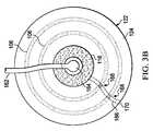
ここで主に図2を参照すると、患者104の組織部位102に減圧をもたらすシステム100の別の説明に役立つ実施形態が示されている。システムは、多くの点で図1のシステム100に類似している。しかしながら、この実施形態では、減圧源140は外部減圧源141であり、および液受け部130はキャニスターまたは他の外部液溜め131である。 Referring now primarily to FIG. 2, an illustrative embodiment is shown that provides another explanation of the
外部減圧源141は、減圧供給導管162によって減圧インターフェース164に流体的に結合されている。説明に役立つ一実施形態では、減圧インターフェース164は、KCI(San Antonio、Texas)から入手可能なT.R.A.C.(登録商標)PadまたはSensa T.R.A.C.(登録商標)Padである。減圧インターフェース164は、分配マニホールド116に減圧を送ることができるようにする。 The external reduced
この説明に役立つ実施形態では、下部または第1のシール部材122のみを使用し、および漏れ検出部材106は、2つの同心部材を含む。漏れ検出部材106を形成する同心部材を図3A〜3Bに最も良く示す。この説明に役立つ実施形態では、下部シール部材122は透明であるため、下部シール部材122の真下の(組織対面側面の)部分は、隠線のない状態で示す。図2のシステム100の他の構造的な特徴は、図1と類似しており、さらに説明はしない。 In this illustrative embodiment, only the lower or
ここで主に図3Aを参照すると、図2のシステムの一部分を平面図で示す。図3Aでは、システム100は起動されていないか、または起動されているが漏れが検出されていないかのいずれかである。漏れ検出部材106に色対比が全くないことによって示すように、漏れは検出されていない。他方で、図3Bでは、漏れ検出部材106の色対比168によって漏れ経路166が示されている。全体的には見えないが(色対比168以外)、漏れ経路166は、縁または外周170で始まって分配マニホールド116まで延びる破線で示し、その分配マニホールドから、漏れが減圧インターフェース164に流れ込む。 Referring now primarily to FIG. 3A, a portion of the system of FIG. 2 is shown in plan view. In FIG. 3A, the
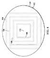
図2〜3Bのシステム100の適用は、図1のシステム100で説明したものと類似している。様々な実施形態において、漏れ検出部材106は多くの形態をとり得ることを留意されたい。漏れ検出部材は、単一のリング、任意の形状の単一の部材、図3A〜3Bに示す同心円などの複数の同心部材、または図4に示す同心の正方形、複数の離間した曲がりセグメント、またはどの方向の漏れ経路も検出できるようにする任意の他の配置とし得る。 The application of the
ここで主に図4を参照すると、下部シール部材122および漏れ検出部材106の説明に役立つ実施形態が示されている。この実施形態では、減圧源140はまだ適用されていない。下部シール部材122には視覚的な印172が含まれて、使用者が、下部シール部材122を組織部位において中心に配置することを支援する。 Referring now primarily to FIG. 4, an illustrative embodiment is shown that illustrates the
ここで主に図5を参照すると、減圧を用いて、患者の組織部位、例えば、図1の組織部位102を治療するシステム200の説明に役立つ実施形態の一部分が示されている。システム200は、多くの点で図1のシステムに類似しており、および類似する部分は、参照符号を100だけ大きくした番号で示した。システム200は、組織部位に近接して配置する分配マニホールド216を含む。システム200はまた、分配マニホールド216と、患者の無傷の表皮の少なくとも一部分とを覆って配置するシール部材222を含む。シール部材222の少なくとも一部分は実質的に透明であり、色対比を見ることができるようにする。シール部材222は、組織対面側面において少なくとも部分的に親水性接着剤276で被覆されるフィルムを含む。親水性接着剤276は、好ましくは、入口点278を囲むパターンにある。入口点278は、シール部材222によって形成された密閉空間に減圧が入る個所である。入口点278は、例えば、減圧インターフェース264が密閉空間に流体的に結合される箇所とし得る。密閉空間は、図1および図2の密閉空間123に類似している。図5の説明に役立つ実施形態では、親水性接着剤276のパターンは、入口点278に比較的近くかつ分配マニホールド216の周辺縁部の中央寄り(inboard)の第1のリング280と、分配マニホールド216の外側の第2のリング282とを含む。 Referring now primarily to FIG. 5, a portion of an embodiment useful for describing a
システム200は、明示しないが図2の外部減圧源141に類似している減圧源を含む。減圧源141は、分配マニホールド216に関連付けられ、減圧を分配マニホールド216にもたらす。減圧の影響下では、組織部位からの流体滲出液は、減圧が作用する箇所で親水性接着剤276と接触され、かつ減圧が作用していない個所では親水性接着剤276に接触されない。それゆえ、漏れ経路266が出現する箇所では、減圧は消失し、かつ滲出液は親水性接着剤276に接触しない。滲出液は色または淡い色(tint)を有するため、漏れが存在するパターン状の親水性接着剤276の位置は、色対比268を示す。先の実施形態と同様に、色対比268は、漏れ経路の位置を示すため、漏れは封止され得る。 The
再度図1〜4を参照して説明すると、説明に役立つ非限定的な実施形態によれば、漏れ検出部材106は、皮膚用調製液としてもよいし、または皮膚用調製液の一態様として含まれてもよい。皮膚用調製液は、一部分が空気にさらされかつ一部分が空気にさらされないときに、色対比を生じる検出材を含む。皮膚用調製液は、少なくとも組織部位の周りに適用される。組織部位は皮膚用調製液によって囲まれる。皮膚用調製液に加えて、皮膚用調製液の非限定的な例として、REDOX色染料または他の染料が含まれてもよい。その後、先に説明したように、下部シール部材122が適用される。漏れが存在する場合、皮膚用調製液にある検出材と接触する空気は、皮膚用調製液に色対比を発生させ、それにより、漏れの位置を示す。別の説明に役立つ実施形態では、皮膚用調製液にはメチレンブルーが適用されている。システム100の他の態様を適用後、減圧が適用され、および下部シール部材122下の、実質的に気密シールされている皮膚用調製液の部分は、酸素が欠乏し、かつ色を、透明(clear)になるように変化させる。漏れのあるどの部分も、空気の流れがあるため青いままとなり、それにより、漏れ位置を示す。 1-4 again, according to a non-limiting embodiment useful for explanation, the
別の説明に役立つ実施形態によれば、減圧を用いて患者104の組織部位102を治療するシステム100は、組織部位102に近接して配置する分配マニホールド116と、分配マニホールド116、および患者104の無傷の表皮110の少なくとも一部分を覆って配置する下部シール部材122とを含む。下部シール部材122の組織対面側面126は、少なくとも部分的に第1の作用物質で被覆される。下部シール部材122の少なくとも一部分は実質的に透明であり、色対比を見ることができるようにする。システム100はまた、分配マニホールド116に関連付けられ分配マニホールド116に減圧をもたらすための減圧源140と、皮膚用調製液とを含む。 According to another illustrative embodiment, a
皮膚用調製液は第2の作用物質を含む。シール部材の第1の作用物質と皮膚用調製液の第2の作用物質が結合すると、それらは、第1の作用物質と第2の作用物質との接触を示す接触色を形成する。それら作用物質が接触しない場所では、色は変化しない。それゆえ、使用時、使用者は、下部シール部材122と患者の表皮110の皮膚用調製液が触れていない場所における色対比を見ることができる。そのような個所は、漏れがありそうな位置であり、および力を加える、例えば、漏れがありそうな位置をこすりつけることによって、または漏れがありそうな位置付近の縁に追加的なシール部材を適用することによって、漏れを封止し得る。 The skin preparation contains a second agent. When the first agent of the seal member and the second agent of the skin preparation are combined, they form a contact color that indicates contact between the first agent and the second agent. Where the agents are not in contact, the color does not change. Therefore, in use, the user can see the color contrast in the area where the
本発明およびその利点を、特定の説明に役立つ非限定的な実施形態に照らして開示したが、添付の特許請求の範囲で定義した本発明の範囲から逸脱せずに、様々な変更、代替、置換、および修正をなし得ることを理解されたい。いずれか一つの実施形態に関連して説明された任意の特徴はまた、任意の他の実施形態にも適用可能であり得ることを理解されたい。 Although the invention and its advantages have been disclosed in the context of non-limiting embodiments that serve a specific description, various changes, substitutions, alternatives have been made without departing from the scope of the invention as defined in the appended claims. It should be understood that substitutions and modifications can be made. It should be understood that any feature described in connection with any one embodiment may also be applicable to any other embodiment.
上述の利益および利点は、一実施形態に関連し得ること、またはいくつかの実施形態に関連し得ることを理解されたい。「1つの(an)」品目への言及は、1つ以上のそれら品目を指すことをさらに理解されたい。 It should be understood that the benefits and advantages described above may relate to one embodiment or may relate to several embodiments. It should be further understood that reference to “an” item refers to one or more of those items.
本明細書で説明した方法のステップは、任意の好適な順序で、または適切な場合には同時に実施し得る。 The method steps described herein may be performed in any suitable order or simultaneously, where appropriate.
適切な場合には、上述の実施形態のいずれかの態様を、説明の任意の他の実施形態の態様と組み合わせて、類似のまたは異なる特性を有しかつ同じまたは異なる問題に対処する別の例を形成する。 Where appropriate, another example of combining any aspect of the above-described embodiments with aspects of any other described embodiment, having similar or different characteristics and addressing the same or different issues Form.
好ましい実施形態の上述の説明は例示にすぎず、当業者は様々な修正をなし得ることを理解されたい。上述の明細書、例、およびデータは、本発明の例示的な実施形態の構造および使用の完全な説明を提供する。本発明の様々な実施形態を、ある程度詳細に、または1つ以上の個々の実施形態を参照して上記で説明したが、当業者は、特許請求の範囲から逸脱せずに、開示の実施形態に多数の修正をなすことができる。 It should be understood that the above description of the preferred embodiments is exemplary only and that various modifications may be made by those skilled in the art. The above specification, examples and data provide a complete description of the structure and use of exemplary embodiments of the invention. Although various embodiments of the invention have been described above in some detail or with reference to one or more individual embodiments, those skilled in the art will recognize that the disclosed embodiments can be used without departing from the scope of the claims. Many modifications can be made.
Claims (11)
Translated fromJapanese前記組織部位に近接して配置する分配マニホールドと;
前記分配マニホールド、および前記患者の無傷の表皮の少なくとも一部分を覆って配置するシール部材であって、少なくとも一部分が実質的に透明であるシール部材と;
前記分配マニホールドに関連付けられて、前記分配マニホールドに減圧をもたらす減圧源と;
前記分配マニホールドを実質的に囲むようなサイズにされかつそのように構成された漏れ検出部材であって、検出材の第一部分が空気にさらされかつ検出材の第二部分が空気にさらされないときに、色対比を生じる検出材を含む漏れ検出部材と
を含むことを特徴とする、システム。In a system for treating a tissue site of a patient using reduced pressure,
A distribution manifold positioned proximate to the tissue site;
A seal member disposed over the distribution manifold and at least a portion of the patient's intact epidermis, wherein at least a portion is substantially transparent;
A vacuum source associated with the distribution manifold to provide a vacuum to the distribution manifold;
A leak detection member sized and configured to substantially surround the distribution manifold, whereinthe first portion ofthe detection material is exposed to air andthe second portionof the detection material is not exposed to air. And a leak detection member including a detection material that produces a color contrast.
前記組織部位に近接して配置する分配マニホールドと;
前記分配マニホールド、および前記患者の無傷の表皮の少なくとも一部分を覆って配置するシール部材であって、少なくとも一部分が実質的に透明であるシール部材と;
前記分配マニホールドに関連付けられて、前記分配マニホールドに減圧をもたらす減圧源と;
前記分配マニホールドを実質的に囲むようなサイズにされかつそのように構成された漏れ検出部材であって、検出材の第一部分が抗体ガスにさらされかつ検出材の第二部分が前記抗体ガスにさらされないときに、色対比を生じる検出材を含む漏れ検出部材と;
前記シール部材に抗体ガスを噴霧するための抗体ガス分配器と
を含むことを特徴とする、システム。In a system for treating a tissue site of a patient using reduced pressure,
A distribution manifold positioned proximate to the tissue site;
A seal member disposed over the distribution manifold and at least a portion of the patient's intact epidermis, wherein at least a portion is substantially transparent;
A vacuum source associated with the distribution manifold to provide a vacuum to the distribution manifold;
Wherein the distribution manifold sized to substantially surround and a leak detection member soarranged,a first portion of thetest design is exposed to the antibody gas and the thesecond partof the detection material antibody A leak detection member including a detection material that produces a color contrast when not exposed to gas;
And an antibody gas distributor for spraying antibody gas onto the seal member.
前記組織部位に近接して配置する分配マニホールドを形成するステップと;
前記分配マニホールド、および前記患者の無傷の表皮の少なくとも一部分を覆って配置するシール部材を形成するステップであって、前記シール部材の少なくとも一部分が実質的に透明であるステップと;
前記分配マニホールドに流体的に結合するための減圧源を提供するステップと;
前記分配マニホールドを実質的に囲むようなサイズにされかつそのように構成された漏れ検出部材を形成するステップであって、前記漏れ検出部材が、検出材の第一部分が空気にさらされかつ検出材の第二部分が空気にさらされないときに、色対比を生じる検出材を含むステップと
を含むことを特徴とする、方法。In a method for manufacturing a system for treating a tissue site of a patient using reduced pressure,
Forming a distribution manifold for placement adjacent to the tissue site;
Forming a seal member for placement over the distribution manifold and at least a portion of the patient's intact epidermis, wherein at least a portion of the seal member is substantially transparent;
Providing a reduced pressure source for fluidly coupling to the distribution manifold;
Forming a leak detection member sized and substantially configured to surround the distribution manifold, wherein the leak detection member exposes anddetects afirst portion ofthe detection material to air. Including a sensing material that produces a color contrast whenthe second portionof the material is not exposed to air.
Applications Claiming Priority (3)
| Application Number | Priority Date | Filing Date | Title |
|---|---|---|---|
| US201161534566P | 2011-09-14 | 2011-09-14 | |
| US61/534,566 | 2011-09-14 | ||
| PCT/US2012/050314WO2013039622A2 (en) | 2011-09-14 | 2012-08-10 | Reduced-pressure systems and methods employing a leak-detection member |
Publications (3)
| Publication Number | Publication Date |
|---|---|
| JP2014526338A JP2014526338A (en) | 2014-10-06 |
| JP2014526338A5 JP2014526338A5 (en) | 2015-09-24 |
| JP6050819B2true JP6050819B2 (en) | 2016-12-21 |
Family
ID=46759044
Family Applications (1)
| Application Number | Title | Priority Date | Filing Date |
|---|---|---|---|
| JP2014530668AExpired - Fee RelatedJP6050819B2 (en) | 2011-09-14 | 2012-08-10 | Pressure reduction system and method using leak detection member |
Country Status (7)
| Country | Link |
|---|---|
| US (2) | US9622914B2 (en) |
| EP (2) | EP3466380A1 (en) |
| JP (1) | JP6050819B2 (en) |
| CN (1) | CN104053419B (en) |
| AU (1) | AU2012309114B2 (en) |
| CA (1) | CA2844663C (en) |
| WO (1) | WO2013039622A2 (en) |
Families Citing this family (117)
| Publication number | Priority date | Publication date | Assignee | Title |
|---|---|---|---|---|
| GB0224986D0 (en) | 2002-10-28 | 2002-12-04 | Smith & Nephew | Apparatus |
| GB0325129D0 (en) | 2003-10-28 | 2003-12-03 | Smith & Nephew | Apparatus in situ |
| US10058642B2 (en) | 2004-04-05 | 2018-08-28 | Bluesky Medical Group Incorporated | Reduced pressure treatment system |
| CA2949821C (en) | 2005-09-06 | 2021-05-18 | Smith & Nephew, Inc. | Self contained wound dressing with micropump |
| US7779625B2 (en) | 2006-05-11 | 2010-08-24 | Kalypto Medical, Inc. | Device and method for wound therapy |
| EP2214612B1 (en) | 2007-11-21 | 2019-05-01 | Smith & Nephew PLC | Wound dressing |
| GB0722820D0 (en) | 2007-11-21 | 2008-01-02 | Smith & Nephew | Vacuum assisted wound dressing |
| GB0723872D0 (en)* | 2007-12-06 | 2008-01-16 | Smith & Nephew | Apparatus for topical negative pressure therapy |
| GB2455962A (en) | 2007-12-24 | 2009-07-01 | Ethicon Inc | Reinforced adhesive backing sheet, for plaster |
| AU2009221772B2 (en) | 2008-03-05 | 2015-01-22 | Solventum Intellectual Properties Company | Dressing and method for applying reduced pressure to and collecting and storing fluid from a tissue site |
| US8152785B2 (en) | 2008-03-13 | 2012-04-10 | Tyco Healthcare Group Lp | Vacuum port for vacuum wound therapy |
| US8814842B2 (en) | 2010-03-16 | 2014-08-26 | Kci Licensing, Inc. | Delivery-and-fluid-storage bridges for use with reduced-pressure systems |
| GB201015656D0 (en) | 2010-09-20 | 2010-10-27 | Smith & Nephew | Pressure control apparatus |
| US9526920B2 (en) | 2010-10-12 | 2016-12-27 | Smith & Nephew, Inc. | Medical device |
| GB201020005D0 (en) | 2010-11-25 | 2011-01-12 | Smith & Nephew | Composition 1-1 |
| CA2819032C (en) | 2010-11-25 | 2020-06-23 | Smith & Nephew Plc | Composition i-ii and products and uses thereof |
| GB2488749A (en) | 2011-01-31 | 2012-09-12 | Systagenix Wound Man Ip Co Bv | Laminated silicone coated wound dressing |
| GB201106491D0 (en) | 2011-04-15 | 2011-06-01 | Systagenix Wound Man Ip Co Bv | Patterened silicone coating |
| GB201108229D0 (en) | 2011-05-17 | 2011-06-29 | Smith & Nephew | Tissue healing |
| WO2013066426A2 (en) | 2011-06-24 | 2013-05-10 | Kci Licensing, Inc. | Reduced-pressure dressings employing tissue-fixation elements |
| JP6050819B2 (en)* | 2011-09-14 | 2016-12-21 | ケーシーアイ ライセンシング インコーポレイテッド | Pressure reduction system and method using leak detection member |
| US9610388B2 (en) | 2011-10-31 | 2017-04-04 | Smith & Nephew, Inc. | Apparatuses and methods for detecting leaks in a negative pressure wound therapy system |
| US9084845B2 (en) | 2011-11-02 | 2015-07-21 | Smith & Nephew Plc | Reduced pressure therapy apparatuses and methods of using same |
| US20150159066A1 (en) | 2011-11-25 | 2015-06-11 | Smith & Nephew Plc | Composition, apparatus, kit and method and uses thereof |
| US10940047B2 (en) | 2011-12-16 | 2021-03-09 | Kci Licensing, Inc. | Sealing systems and methods employing a hybrid switchable drape |
| CN103987348B (en) | 2011-12-16 | 2016-05-11 | 凯希特许有限公司 | Releasable Medical Drapes |
| AU2013237095B2 (en) | 2012-03-20 | 2017-10-05 | Smith & Nephew Plc | Controlling operation of a reduced pressure therapy system based on dynamic duty cycle threshold determination |
| JP6400570B2 (en) | 2012-05-23 | 2018-10-10 | スミス アンド ネフュー ピーエルシーSmith & Nephew Public Limited Company | Apparatus and method for local negative pressure closure therapy |
| WO2014020440A1 (en) | 2012-08-01 | 2014-02-06 | Smith & Nephew Plc | Wound dressing |
| CN108186200B (en) | 2012-08-01 | 2021-08-10 | 史密夫及内修公开有限公司 | Wound dressing |
| AU2013344686B2 (en) | 2012-11-16 | 2018-06-21 | Solventum Intellectual Properties Company | Medical drape with pattern adhesive layers and method of manufacturing same |
| GB201222770D0 (en) | 2012-12-18 | 2013-01-30 | Systagenix Wound Man Ip Co Bv | Wound dressing with adhesive margin |
| GB201317746D0 (en) | 2013-10-08 | 2013-11-20 | Smith & Nephew | PH indicator |
| GB201317742D0 (en)* | 2013-10-08 | 2013-11-20 | Smith & Nephew | Ph indicator dressing |
| GB201401112D0 (en)* | 2014-01-23 | 2014-03-12 | Smith & Nephew | Systems and methods for wound monitoring |
| US9737649B2 (en) | 2013-03-14 | 2017-08-22 | Smith & Nephew, Inc. | Systems and methods for applying reduced pressure therapy |
| JP2016517318A (en) | 2013-03-14 | 2016-06-16 | スミス アンド ネフュー インコーポレーテッド | System and method for administering decompression therapy |
| CN105407932A (en) | 2013-03-15 | 2016-03-16 | 史密夫及内修公开有限公司 | Wound dressing and method of treatment |
| US10695226B2 (en) | 2013-03-15 | 2020-06-30 | Smith & Nephew Plc | Wound dressing and method of treatment |
| EP2968647B1 (en) | 2013-03-15 | 2022-06-29 | Smith & Nephew plc | Wound dressing sealant and use thereof |
| US20160120706A1 (en) | 2013-03-15 | 2016-05-05 | Smith & Nephew Plc | Wound dressing sealant and use thereof |
| WO2015023515A1 (en) | 2013-08-13 | 2015-02-19 | Smith & Nephew, Inc. | Systems and methods for applying reduced pressure therapy |
| EP3038667B1 (en) | 2013-08-26 | 2019-10-09 | KCI Licensing, Inc. | Dressing interface with moisture controlling feature and sealing function |
| US10946124B2 (en) | 2013-10-28 | 2021-03-16 | Kci Licensing, Inc. | Hybrid sealing tape |
| US9956120B2 (en) | 2013-10-30 | 2018-05-01 | Kci Licensing, Inc. | Dressing with sealing and retention interface |
| EP3527237B1 (en) | 2013-10-30 | 2020-09-09 | KCI Licensing, Inc. | Absorbent conduit and system |
| EP3062751B1 (en) | 2013-10-30 | 2017-08-09 | KCI Licensing, Inc. | Condensate absorbing and dissipating system |
| AU2014342903B2 (en)* | 2013-10-30 | 2018-09-20 | Solventum Intellectual Properties Company | Dressing with differentially sized perforations |
| EP3110379B1 (en) | 2014-02-28 | 2019-04-03 | KCI Licensing, Inc. | Hybrid drape having a gel-coated perforated mesh |
| US11026844B2 (en) | 2014-03-03 | 2021-06-08 | Kci Licensing, Inc. | Low profile flexible pressure transmission conduit |
| EP2926781A1 (en) | 2014-04-01 | 2015-10-07 | Paul Hartmann AG | Dressing set for negative pressure therapy |
| US10531977B2 (en) | 2014-04-17 | 2020-01-14 | Coloplast A/S | Thermoresponsive skin barrier appliances |
| WO2015168681A1 (en)* | 2014-05-02 | 2015-11-05 | Kci Licensing, Inc. | Fluid storage devices, systems, and methods |
| JP6640748B2 (en) | 2014-06-05 | 2020-02-05 | ケーシーアイ ライセンシング インコーポレイテッド | Dressing with fluid acquisition and dispensing features |
| US10610414B2 (en) | 2014-06-18 | 2020-04-07 | Smith & Nephew Plc | Wound dressing and method of treatment |
| WO2016005288A1 (en) | 2014-07-10 | 2016-01-14 | Smith & Nephew Plc | Improvements in and relating to polymer materials |
| CA3179001A1 (en) | 2014-07-31 | 2016-02-04 | Smith & Nephew, Inc. | Systems and methods for applying reduced pressure therapy |
| US12133789B2 (en) | 2014-07-31 | 2024-11-05 | Smith & Nephew, Inc. | Reduced pressure therapy apparatus construction and control |
| WO2016100098A1 (en) | 2014-12-17 | 2016-06-23 | Kci Licensing, Inc. | Dressing with offloading capability |
| EP3237032B1 (en) | 2014-12-22 | 2024-08-07 | Smith & Nephew plc | Negative pressure wound therapy apparatus |
| EP3574877B1 (en) | 2015-05-08 | 2022-08-17 | 3M Innovative Properties Company | Low-acuity dressing with integral pump |
| US10076594B2 (en) | 2015-05-18 | 2018-09-18 | Smith & Nephew Plc | Fluidic connector for negative pressure wound therapy |
| EP3741335B1 (en) | 2015-09-01 | 2023-05-24 | KCI Licensing, Inc. | Dressing with increased apposition force |
| EP3349807B1 (en) | 2015-09-17 | 2021-02-24 | 3M Innovative Properties Company | Hybrid silicone and acrylic adhesive cover for use with wound treatment |
| US11364150B2 (en) | 2015-12-30 | 2022-06-21 | Smith & Nephew Plc | Negative pressure wound therapy apparatus |
| US11090196B2 (en) | 2015-12-30 | 2021-08-17 | Smith & Nephew Plc | Absorbent negative pressure wound therapy dressing |
| GB201600747D0 (en) | 2016-01-14 | 2016-03-02 | Smith & Nephew | Improvements in and relating to devices |
| GB201600746D0 (en) | 2016-01-14 | 2016-03-02 | Smith & Nephew | Improvements in and relating to polymer materials |
| USD796735S1 (en) | 2016-02-29 | 2017-09-05 | Smith & Nephew Plc | Mount apparatus for portable negative pressure apparatus |
| JP1586116S (en) | 2016-02-29 | 2017-09-19 | ||
| WO2017148824A1 (en) | 2016-03-04 | 2017-09-08 | Smith & Nephew Plc | Negative pressure wound therapy apparatus for post breast surgery wounds |
| CN109069713A (en) | 2016-05-13 | 2018-12-21 | 史密夫和内修有限公司 | Automatic wound in negative pressure wound treating system couples detection |
| EP3551147B1 (en) | 2016-12-12 | 2023-08-09 | Smith & Nephew PLC | Wound dressing |
| JP7155162B2 (en) | 2017-06-14 | 2022-10-18 | ティージェイ スミス アンド ネフュー リミテッド | Negative pressure wound therapy unit |
| EP3687602A4 (en)* | 2017-09-27 | 2021-06-23 | Becton, Dickinson and Company | LEAK DETECTION LIQUID ADMINISTRATION DEVICE |
| JP2021508269A (en) | 2017-12-22 | 2021-03-04 | コロプラスト アクティーゼルスカブ | A method for manufacturing a base plate for an ostomy orthosis and a sensor assembly part for the base plate, and a base plate and a sensor assembly part. |
| EP3727222B1 (en) | 2017-12-22 | 2024-05-08 | Coloplast A/S | Sensor assembly part for an ostomy appliance and a method for manufacturing a sensor assembly part |
| EP3727245B1 (en) | 2017-12-22 | 2025-04-30 | Coloplast A/S | Data transmission schemes for an ostomy system, monitoring device for an ostomy device, and associated methods |
| US11707377B2 (en) | 2017-12-22 | 2023-07-25 | Coloplast A/S | Coupling part with a hinge for a medical base plate and sensor assembly part |
| LT3727228T (en) | 2017-12-22 | 2022-08-10 | Coloplast A/S | MAIN BOARD AND SENSOR STRUCTURE PART FOR OSTOMY DEVICE AND METHOD OF MANUFACTURING THE MAIN BOARD AND SENSOR STRUCTURE PART |
| EP4032511A1 (en) | 2017-12-22 | 2022-07-27 | Coloplast A/S | Ostomy appliance with sensing zones |
| WO2019120441A1 (en) | 2017-12-22 | 2019-06-27 | Coloplast A/S | Sensor assembly part and a base plate for an ostomy appliance and a method for manufacturing a sensor assembly part and a base plate |
| EP4245273A3 (en) | 2017-12-22 | 2023-11-08 | Coloplast A/S | Base plate and sensor assembly of an ostomy system having a leakage sensor |
| US10500084B2 (en) | 2017-12-22 | 2019-12-10 | Coloplast A/S | Accessory devices of an ostomy system, and related methods for communicating leakage state |
| EP4042987B1 (en) | 2017-12-22 | 2025-02-12 | Coloplast A/S | Monitor device of an ostomy system having a connector for coupling to both a base plate and an accessory device |
| EP3727219B1 (en) | 2017-12-22 | 2023-08-09 | Coloplast A/S | Moisture detecting base plate for an ostomy appliance and a system for determining moisture propagation in a base plate and/or a sensor assembly part |
| US10799385B2 (en) | 2017-12-22 | 2020-10-13 | Coloplast A/S | Ostomy appliance with layered base plate |
| US10849781B2 (en) | 2017-12-22 | 2020-12-01 | Coloplast A/S | Base plate for an ostomy appliance |
| EP3727231B2 (en) | 2017-12-22 | 2025-03-12 | Coloplast A/S | Processing schemes for an ostomy system, monitor device for an ostomy appliance and related methods |
| US11607334B2 (en) | 2017-12-22 | 2023-03-21 | Coloplast A/S | Base plate for a medical appliance, a monitor device and a system for a medical appliance |
| WO2019120431A1 (en) | 2017-12-22 | 2019-06-27 | Coloplast A/S | Tools and methods for cutting holes in an ostomy appliance |
| EP4248920A3 (en) | 2017-12-22 | 2023-12-27 | Coloplast A/S | Ostomy appliance system, monitor device, and method of monitoring an ostomy appliance |
| US11627891B2 (en) | 2017-12-22 | 2023-04-18 | Coloplast A/S | Calibration methods for medical appliance tools |
| WO2019120442A1 (en) | 2017-12-22 | 2019-06-27 | Coloplast A/S | Sensor assembly part and a base plate for an ostomy appliance and a device for connecting to a base plate or a sensor assembly part |
| US11654043B2 (en) | 2017-12-22 | 2023-05-23 | Coloplast A/S | Sensor assembly part and a base plate for a medical appliance and a method for manufacturing a base plate or a sensor assembly part |
| US11471318B2 (en) | 2017-12-22 | 2022-10-18 | Coloplast A/S | Data collection schemes for a medical appliance and related methods |
| DK3729456T3 (en) | 2017-12-22 | 2022-03-07 | Coloplast As | MONITORING DEVICE FOR AN OSTOMY SYSTEM AND ASSOCIATED METHOD FOR OPERATING A MONITORING DEVICE |
| LT4032510T (en) | 2017-12-22 | 2025-08-25 | Coloplast A/S | BASE BOARD WITH SELECTIVE SENSOR POINTS AND METHOD FOR MANUFACTURING THEREOF |
| AU2018391313B2 (en) | 2017-12-22 | 2024-05-02 | Coloplast A/S | Accessory devices of an ostomy system, and related methods for communicating operating state |
| JP7462558B2 (en) | 2017-12-22 | 2024-04-05 | コロプラスト アクティーゼルスカブ | Ostomy system and monitor device with angular leak detection - Patents.com |
| WO2019120438A1 (en) | 2017-12-22 | 2019-06-27 | Coloplast A/S | Tools and methods for placing an ostomy appliance on a user |
| US12208029B2 (en) | 2018-02-20 | 2025-01-28 | Coloplast A/S | Base plate having a mechanical and electrical connector |
| EP4631480A2 (en) | 2018-02-20 | 2025-10-15 | Coloplast A/S | Accessory devices of an ostomy system, and related methods for changing an ostomy appliance based on future operating state |
| WO2019161861A1 (en) | 2018-02-20 | 2019-08-29 | Coloplast A/S | Sensor assembly part and a base plate for an ostomy appliance and a device for connecting to a base plate and/or a sensor assembly part |
| US11903728B2 (en)* | 2018-03-15 | 2024-02-20 | Coloplast A/S | Methods of configuring medical notifications and related accessory devices |
| US11998474B2 (en) | 2018-03-15 | 2024-06-04 | Coloplast A/S | Apparatus and methods for navigating ostomy appliance user to changing room |
| EP3837520B1 (en) | 2018-08-15 | 2025-10-08 | Coloplast A/S | Accessory device of an ostomy system and related methods for issue identification |
| EP3897482B1 (en) | 2018-12-20 | 2025-07-16 | Coloplast A/S | Ostomy condition classification with image data transformation, devices and related methods |
| EP3897481B1 (en) | 2018-12-20 | 2023-08-09 | Coloplast A/S | Ostomy condition classification with masking, devices and related methods |
| CN113365582B (en) | 2019-01-31 | 2024-12-31 | 科洛普拉斯特公司 | Stoma Sensor Patch |
| WO2020156624A1 (en) | 2019-01-31 | 2020-08-06 | Coloplast A/S | Application of a stomal sensor patch |
| KR102825171B1 (en) | 2019-01-31 | 2025-06-25 | 컬러플라스트 에이/에스 | Sensor patch for ostomy/urinary device |
| US11612512B2 (en) | 2019-01-31 | 2023-03-28 | Coloplast A/S | Moisture detecting base plate for an ostomy appliance and a system for determining moisture propagation in a base plate and/or a sensor assembly part |
| US12257172B2 (en) | 2019-02-28 | 2025-03-25 | Coloplast A/S | Sensor patch for attachment to a base plate |
| DE202019101382U1 (en)* | 2019-03-12 | 2020-06-15 | Lohmann & Rauscher Gmbh | Vacuum treatment arrangement |
| GB202001212D0 (en) | 2020-01-29 | 2020-03-11 | Smith & Nephew | Systems and methods for measuring and tracking wound volume |
| EP4512377A3 (en) | 2020-04-14 | 2025-04-30 | Coloplast A/S | METHOD FOR A MONITORING DEVICE FOR A PERSONAL CARE SYSTEM |
Family Cites Families (191)
| Publication number | Priority date | Publication date | Assignee | Title |
|---|---|---|---|---|
| US1355846A (en) | 1920-02-06 | 1920-10-19 | David A Rannells | Medical appliance |
| US2547758A (en) | 1949-01-05 | 1951-04-03 | Wilmer B Keeling | Instrument for treating the male urethra |
| US2632443A (en) | 1949-04-18 | 1953-03-24 | Eleanor P Lesher | Surgical dressing |
| GB692578A (en) | 1949-09-13 | 1953-06-10 | Minnesota Mining & Mfg | Improvements in or relating to drape sheets for surgical use |
| US2682873A (en) | 1952-07-30 | 1954-07-06 | Johnson & Johnson | General purpose protective dressing |
| NL189176B (en) | 1956-07-13 | 1900-01-01 | Hisamitsu Pharmaceutical Co | PLASTER BASED ON A SYNTHETIC RUBBER. |
| US2969057A (en) | 1957-11-04 | 1961-01-24 | Brady Co W H | Nematodic swab |
| US3066672A (en) | 1960-09-27 | 1962-12-04 | Jr William H Crosby | Method and apparatus for serial sampling of intestinal juice |
| US3367332A (en) | 1965-08-27 | 1968-02-06 | Gen Electric | Product and process for establishing a sterile area of skin |
| US3520300A (en) | 1967-03-15 | 1970-07-14 | Amp Inc | Surgical sponge and suction device |
| US3568675A (en) | 1968-08-30 | 1971-03-09 | Clyde B Harvey | Fistula and penetrating wound dressing |
| US3682180A (en) | 1970-06-08 | 1972-08-08 | Coilform Co Inc | Drain clip for surgical drain |
| BE789293Q (en) | 1970-12-07 | 1973-01-15 | Parke Davis & Co | MEDICO-SURGICAL DRESSING FOR BURNS AND SIMILAR LESIONS |
| US3902484A (en)* | 1972-02-07 | 1975-09-02 | Kimberly Clark Co | Disposable surgical drape |
| US3826254A (en) | 1973-02-26 | 1974-07-30 | Verco Ind | Needle or catheter retaining appliance |
| DE2527706A1 (en) | 1975-06-21 | 1976-12-30 | Hanfried Dr Med Weigand | DEVICE FOR THE INTRODUCTION OF CONTRAST AGENTS INTO AN ARTIFICIAL INTESTINAL OUTLET |
| CA1056340A (en)* | 1976-05-27 | 1979-06-12 | Marion Laboratories | Anaerobic liquid transport apparatus |
| DE2640413C3 (en) | 1976-09-08 | 1980-03-27 | Richard Wolf Gmbh, 7134 Knittlingen | Catheter monitor |
| NL7710909A (en) | 1976-10-08 | 1978-04-11 | Smith & Nephew | COMPOSITE STRAPS. |
| GB1562244A (en) | 1976-11-11 | 1980-03-05 | Lock P M | Wound dressing materials |
| US4080970A (en) | 1976-11-17 | 1978-03-28 | Miller Thomas J | Post-operative combination dressing and internal drain tube with external shield and tube connector |
| US4139004A (en) | 1977-02-17 | 1979-02-13 | Gonzalez Jr Harry | Bandage apparatus for treating burns |
| US4184510A (en) | 1977-03-15 | 1980-01-22 | Fibra-Sonics, Inc. | Valued device for controlling vacuum in surgery |
| US4165748A (en) | 1977-11-07 | 1979-08-28 | Johnson Melissa C | Catheter tube holder |
| US4245637A (en) | 1978-07-10 | 1981-01-20 | Nichols Robert L | Shutoff valve sleeve |
| SE414994B (en) | 1978-11-28 | 1980-09-01 | Landstingens Inkopscentral | VENKATETERFORBAND |
| GB2047543B (en) | 1978-12-06 | 1983-04-20 | Svedman Paul | Device for treating tissues for example skin |
| US4266545A (en) | 1979-04-06 | 1981-05-12 | Moss James P | Portable suction device for collecting fluids from a closed wound |
| US4284079A (en) | 1979-06-28 | 1981-08-18 | Adair Edwin Lloyd | Method for applying a male incontinence device |
| US4261363A (en) | 1979-11-09 | 1981-04-14 | C. R. Bard, Inc. | Retention clips for body fluid drains |
| US4569348A (en) | 1980-02-22 | 1986-02-11 | Velcro Usa Inc. | Catheter tube holder strap |
| WO1981002516A1 (en) | 1980-03-11 | 1981-09-17 | E Schmid | Cushion for holding an element of grafted skin |
| US4297995A (en) | 1980-06-03 | 1981-11-03 | Key Pharmaceuticals, Inc. | Bandage containing attachment post |
| US4333468A (en) | 1980-08-18 | 1982-06-08 | Geist Robert W | Mesentery tube holder apparatus |
| US4465485A (en) | 1981-03-06 | 1984-08-14 | Becton, Dickinson And Company | Suction canister with unitary shut-off valve and filter features |
| US4392853A (en) | 1981-03-16 | 1983-07-12 | Rudolph Muto | Sterile assembly for protecting and fastening an indwelling device |
| US4373519A (en) | 1981-06-26 | 1983-02-15 | Minnesota Mining And Manufacturing Company | Composite wound dressing |
| US4392858A (en) | 1981-07-16 | 1983-07-12 | Sherwood Medical Company | Wound drainage device |
| US4419097A (en) | 1981-07-31 | 1983-12-06 | Rexar Industries, Inc. | Attachment for catheter tube |
| AU550575B2 (en) | 1981-08-07 | 1986-03-27 | Richard Christian Wright | Wound drainage device |
| SE429197B (en) | 1981-10-14 | 1983-08-22 | Frese Nielsen | SAR TREATMENT DEVICE |
| DE3146266A1 (en) | 1981-11-21 | 1983-06-01 | B. Braun Melsungen Ag, 3508 Melsungen | COMBINED DEVICE FOR A MEDICAL SUCTION DRAINAGE |
| US4551139A (en) | 1982-02-08 | 1985-11-05 | Marion Laboratories, Inc. | Method and apparatus for burn wound treatment |
| US4475909A (en) | 1982-05-06 | 1984-10-09 | Eisenberg Melvin I | Male urinary device and method for applying the device |
| EP0100148B1 (en) | 1982-07-06 | 1986-01-08 | Dow Corning Limited | Medical-surgical dressing and a process for the production thereof |
| NZ206837A (en) | 1983-01-27 | 1986-08-08 | Johnson & Johnson Prod Inc | Thin film adhesive dressing:backing material in three sections |
| US4548202A (en) | 1983-06-20 | 1985-10-22 | Ethicon, Inc. | Mesh tissue fasteners |
| US4540412A (en) | 1983-07-14 | 1985-09-10 | The Kendall Company | Device for moist heat therapy |
| US4543100A (en) | 1983-11-01 | 1985-09-24 | Brodsky Stuart A | Catheter and drain tube retainer |
| US4525374A (en) | 1984-02-27 | 1985-06-25 | Manresa, Inc. | Treating hydrophobic filters to render them hydrophilic |
| CA1286177C (en) | 1984-05-03 | 1991-07-16 | Smith And Nephew Associated Companies Plc | Adhesive wound dressing |
| US4897081A (en) | 1984-05-25 | 1990-01-30 | Thermedics Inc. | Percutaneous access device |
| US5215522A (en) | 1984-07-23 | 1993-06-01 | Ballard Medical Products | Single use medical aspirating device and method |
| GB8419745D0 (en) | 1984-08-02 | 1984-09-05 | Smith & Nephew Ass | Wound dressing |
| US4872450A (en) | 1984-08-17 | 1989-10-10 | Austad Eric D | Wound dressing and method of forming same |
| US4826494A (en) | 1984-11-09 | 1989-05-02 | Stryker Corporation | Vacuum wound drainage system |
| US4655754A (en) | 1984-11-09 | 1987-04-07 | Stryker Corporation | Vacuum wound drainage system and lipids baffle therefor |
| US4605399A (en) | 1984-12-04 | 1986-08-12 | Complex, Inc. | Transdermal infusion device |
| US4822743A (en)* | 1984-12-13 | 1989-04-18 | Lockheed Corporation | Method and cloth for detecting leaks in closed bodies |
| US5037397A (en) | 1985-05-03 | 1991-08-06 | Medical Distributors, Inc. | Universal clamp |
| US4640688A (en) | 1985-08-23 | 1987-02-03 | Mentor Corporation | Urine collection catheter |
| US4710165A (en) | 1985-09-16 | 1987-12-01 | Mcneil Charles B | Wearable, variable rate suction/collection device |
| US4758220A (en) | 1985-09-26 | 1988-07-19 | Alcon Laboratories, Inc. | Surgical cassette proximity sensing and latching apparatus |
| US4733659A (en) | 1986-01-17 | 1988-03-29 | Seton Company | Foam bandage |
| EP0256060A1 (en) | 1986-01-31 | 1988-02-24 | OSMOND, Roger L. W. | Suction system for wound and gastro-intestinal drainage |
| US4838883A (en) | 1986-03-07 | 1989-06-13 | Nissho Corporation | Urine-collecting device |
| JPS62281965A (en) | 1986-05-29 | 1987-12-07 | テルモ株式会社 | Catheter and catheter fixing member |
| ES8800028A1 (en)* | 1986-06-25 | 1987-11-01 | Fuchelman Sa | Contour type electrosurgical dispersive electrode. |
| GB8621884D0 (en) | 1986-09-11 | 1986-10-15 | Bard Ltd | Catheter applicator |
| GB2195255B (en) | 1986-09-30 | 1991-05-01 | Vacutec Uk Limited | Apparatus for vacuum treatment of an epidermal surface |
| US4743232A (en) | 1986-10-06 | 1988-05-10 | The Clinipad Corporation | Package assembly for plastic film bandage |
| DE3634569A1 (en) | 1986-10-10 | 1988-04-21 | Sachse Hans E | CONDOM CATHETER, A URINE TUBE CATHETER FOR PREVENTING RISING INFECTIONS |
| JPS63135179A (en) | 1986-11-26 | 1988-06-07 | 立花 俊郎 | Subcataneous drug administration set |
| GB8628564D0 (en) | 1986-11-28 | 1987-01-07 | Smiths Industries Plc | Anti-foaming agent suction apparatus |
| GB2199498B (en)* | 1987-01-06 | 1990-07-04 | John Garth Jessamine | Surgical isolation drapes |
| US4988342A (en)* | 1987-03-02 | 1991-01-29 | Atrium Medical Corporation | Improved fluid recovery system |
| GB8706116D0 (en) | 1987-03-14 | 1987-04-15 | Smith & Nephew Ass | Adhesive dressings |
| US4787888A (en) | 1987-06-01 | 1988-11-29 | University Of Connecticut | Disposable piezoelectric polymer bandage for percutaneous delivery of drugs and method for such percutaneous delivery (a) |
| US4863449A (en) | 1987-07-06 | 1989-09-05 | Hollister Incorporated | Adhesive-lined elastic condom cathether |
| US5176663A (en) | 1987-12-02 | 1993-01-05 | Pal Svedman | Dressing having pad with compressibility limiting elements |
| US4906240A (en) | 1988-02-01 | 1990-03-06 | Matrix Medica, Inc. | Adhesive-faced porous absorbent sheet and method of making same |
| US4985019A (en) | 1988-03-11 | 1991-01-15 | Michelson Gary K | X-ray marker |
| GB8812803D0 (en) | 1988-05-28 | 1988-06-29 | Smiths Industries Plc | Medico-surgical containers |
| US4919654A (en) | 1988-08-03 | 1990-04-24 | Kalt Medical Corporation | IV clamp with membrane |
| US5000741A (en) | 1988-08-22 | 1991-03-19 | Kalt Medical Corporation | Transparent tracheostomy tube dressing |
| US4869271A (en)* | 1988-12-16 | 1989-09-26 | Kimberly-Clark Corporation | Bi-lateral surgical drape |
| US5059596A (en) | 1989-01-16 | 1991-10-22 | Roussel Uclaf | Azabicyclo compounds |
| GB8906100D0 (en) | 1989-03-16 | 1989-04-26 | Smith & Nephew | Laminates |
| US4969880A (en) | 1989-04-03 | 1990-11-13 | Zamierowski David S | Wound dressing and treatment method |
| US5100396A (en) | 1989-04-03 | 1992-03-31 | Zamierowski David S | Fluidic connection system and method |
| US5527293A (en) | 1989-04-03 | 1996-06-18 | Kinetic Concepts, Inc. | Fastening system and method |
| US5261893A (en) | 1989-04-03 | 1993-11-16 | Zamierowski David S | Fastening system and method |
| JP2719671B2 (en) | 1989-07-11 | 1998-02-25 | 日本ゼオン株式会社 | Wound dressing |
| US5358494A (en) | 1989-07-11 | 1994-10-25 | Svedman Paul | Irrigation dressing |
| US5232453A (en) | 1989-07-14 | 1993-08-03 | E. R. Squibb & Sons, Inc. | Catheter holder |
| GB2235877A (en) | 1989-09-18 | 1991-03-20 | Antonio Talluri | Closed wound suction apparatus |
| US5218212A (en)* | 1989-11-24 | 1993-06-08 | Mitsubishi Denki Kabushiki Kaisha | Device for optically detecting a chemical change in fluid |
| US5134994A (en) | 1990-02-12 | 1992-08-04 | Say Sam L | Field aspirator in a soft pack with externally mounted container |
| US5092858A (en) | 1990-03-20 | 1992-03-03 | Becton, Dickinson And Company | Liquid gelling agent distributor device |
| US5386835A (en)* | 1990-03-30 | 1995-02-07 | Elphick; Kevin J. | Barrier means |
| US5183763A (en)* | 1990-06-06 | 1993-02-02 | Southwest Research Institute | Composition and method for detecting vapor and liquid reactants |
| JP2941918B2 (en) | 1990-09-19 | 1999-08-30 | テルモ株式会社 | Weighing device |
| US5149331A (en) | 1991-05-03 | 1992-09-22 | Ariel Ferdman | Method and device for wound closure |
| US5278100A (en) | 1991-11-08 | 1994-01-11 | Micron Technology, Inc. | Chemical vapor deposition technique for depositing titanium silicide on semiconductor wafers |
| US5645081A (en) | 1991-11-14 | 1997-07-08 | Wake Forest University | Method of treating tissue damage and apparatus for same |
| US5636643A (en) | 1991-11-14 | 1997-06-10 | Wake Forest University | Wound treatment employing reduced pressure |
| US5279550A (en) | 1991-12-19 | 1994-01-18 | Gish Biomedical, Inc. | Orthopedic autotransfusion system |
| US5167613A (en) | 1992-03-23 | 1992-12-01 | The Kendall Company | Composite vented wound dressing |
| FR2690617B1 (en) | 1992-04-29 | 1994-06-24 | Cbh Textile | TRANSPARENT ADHESIVE DRESSING. |
| FI94802C (en) | 1992-06-03 | 1995-10-25 | Valtion Teknillinen | Protective gas packaging and leakage indicator |
| DE4306478A1 (en) | 1993-03-02 | 1994-09-08 | Wolfgang Dr Wagner | Drainage device, in particular pleural drainage device, and drainage method |
| US6241747B1 (en) | 1993-05-03 | 2001-06-05 | Quill Medical, Inc. | Barbed Bodily tissue connector |
| US5342376A (en) | 1993-05-03 | 1994-08-30 | Dermagraphics, Inc. | Inserting device for a barbed tissue connector |
| US5344415A (en) | 1993-06-15 | 1994-09-06 | Deroyal Industries, Inc. | Sterile system for dressing vascular access site |
| US5437651A (en) | 1993-09-01 | 1995-08-01 | Research Medical, Inc. | Medical suction apparatus |
| US5549584A (en) | 1994-02-14 | 1996-08-27 | The Kendall Company | Apparatus for removing fluid from a wound |
| US5383476A (en)* | 1994-05-24 | 1995-01-24 | Peimer; Clayton | Surgical drape for surgery on an extremity |
| US5556375A (en) | 1994-06-16 | 1996-09-17 | Hercules Incorporated | Wound dressing having a fenestrated base layer |
| US5607388A (en) | 1994-06-16 | 1997-03-04 | Hercules Incorporated | Multi-purpose wound dressing |
| US5664270A (en) | 1994-07-19 | 1997-09-09 | Kinetic Concepts, Inc. | Patient interface system |
| DE69505545T2 (en) | 1994-08-22 | 1999-03-11 | Kinetic Concepts Inc | WOUND DRAINAGE DEVICE |
| US5753285A (en)* | 1995-02-16 | 1998-05-19 | Horan; Thomas J. | Method for determining bacteria contamination in food package |
| DE29504378U1 (en) | 1995-03-15 | 1995-09-14 | MTG Medizinisch, technische Gerätebau GmbH, 66299 Friedrichsthal | Electronically controlled low-vacuum pump for chest and wound drainage |
| US6070454A (en)* | 1995-07-21 | 2000-06-06 | Bright Solutions, Inc. | Leak detection additives for use in heating, ventilating, refrigeration, and air conditioning systems |
| US6070455A (en)* | 1995-07-21 | 2000-06-06 | Bright Solutions, Inc. | Leak detection additives |
| US5704905A (en)* | 1995-10-10 | 1998-01-06 | Jensen; Ole R. | Wound dressing having film-backed hydrocolloid-containing adhesive layer with linear depressions |
| GB9523253D0 (en) | 1995-11-14 | 1996-01-17 | Mediscus Prod Ltd | Portable wound treatment apparatus |
| US5816252A (en)* | 1997-04-29 | 1998-10-06 | O.R. Solutions, Inc. | Surgical drape leak detection method and apparatus |
| EP0993610A1 (en)* | 1997-07-16 | 2000-04-19 | THE GOVERNMENT OF THE UNITED STATES OF AMERICA, as represented by THE SECRETARY, DEPARTMENT OF HEALTH AND HUMAN SERVICES | Food quality indicator device |
| US6135116A (en) | 1997-07-28 | 2000-10-24 | Kci Licensing, Inc. | Therapeutic method for treating ulcers |
| GB9719520D0 (en) | 1997-09-12 | 1997-11-19 | Kci Medical Ltd | Surgical drape and suction heads for wound treatment |
| AU755496B2 (en) | 1997-09-12 | 2002-12-12 | Kci Licensing, Inc. | Surgical drape and suction head for wound treatment |
| US5979226A (en)* | 1998-02-05 | 1999-11-09 | Bright Solutions, Inc. | Leak detection additives for oil or fuel systems |
| US6071267A (en) | 1998-02-06 | 2000-06-06 | Kinetic Concepts, Inc. | Medical patient fluid management interface system and method |
| US6488643B1 (en) | 1998-10-08 | 2002-12-03 | Kci Licensing, Inc. | Wound healing foot wrap |
| US7709694B2 (en)* | 1998-12-08 | 2010-05-04 | Quick-Med Technologies, Inc. | Materials with covalently-bonded, nonleachable, polymeric antimicrobial surfaces |
| US6287316B1 (en) | 1999-03-26 | 2001-09-11 | Ethicon, Inc. | Knitted surgical mesh |
| US6856821B2 (en) | 2000-05-26 | 2005-02-15 | Kci Licensing, Inc. | System for combined transcutaneous blood gas monitoring and vacuum assisted wound closure |
| US7799004B2 (en) | 2001-03-05 | 2010-09-21 | Kci Licensing, Inc. | Negative pressure wound treatment apparatus and infection identification system and method |
| US6991643B2 (en) | 2000-12-20 | 2006-01-31 | Usgi Medical Inc. | Multi-barbed device for retaining tissue in apposition and methods of use |
| ES2220734T3 (en) | 2000-02-24 | 2004-12-16 | Venetec International, Inc. | UNIVERSAL FIXING SYSTEM FOR CATETER. |
| GB0011202D0 (en)* | 2000-05-09 | 2000-06-28 | Kci Licensing Inc | Abdominal wound dressing |
| US6540705B2 (en) | 2001-02-22 | 2003-04-01 | Core Products International, Inc. | Ankle brace providing upper and lower ankle adjustment |
| US7858679B2 (en)* | 2001-07-20 | 2010-12-28 | Northwestern University | Polymeric compositions and related methods of use |
| GB0121444D0 (en)* | 2001-09-05 | 2001-10-24 | Univ Strathclyde | Sensor |
| US7854230B2 (en)* | 2001-10-22 | 2010-12-21 | O.R. Solutions, Inc. | Heated medical instrument stand with surgical drape and method of detecting fluid and leaks in the stand tray |
| US7347210B2 (en)* | 2001-10-22 | 2008-03-25 | O.R. Solutions, Inc. | Surgical drape with conductor and method of detecting fluid and leaks in thermal treatment system Basins |
| US7959860B2 (en)* | 2001-10-22 | 2011-06-14 | Faries Jr Durward I | System and method of detecting fluid and leaks in thermal treatment system basins |
| US7418966B2 (en)* | 2001-10-22 | 2008-09-02 | O. R. Solutions, Inc. | Surgical drape and method of detecting fluid and leaks in thermal treatment system basins |
| US7846141B2 (en) | 2002-09-03 | 2010-12-07 | Bluesky Medical Group Incorporated | Reduced pressure treatment system |
| US20090238811A1 (en)* | 2002-09-09 | 2009-09-24 | Mcdaniel C Steven | Enzymatic Antimicrobial and Antifouling Coatings and Polymeric Materials |
| US20100233146A1 (en)* | 2002-09-09 | 2010-09-16 | Reactive Surfaces, Ltd. | Coatings and Surface Treatments Having Active Enzymes and Peptides |
| US20110250626A1 (en)* | 2002-09-09 | 2011-10-13 | Reactive Surfaces, Ltd. | Visual Assays for Coatings Incorporating Bioactive Enzymes for Catalytic Functions |
| GB0224986D0 (en) | 2002-10-28 | 2002-12-04 | Smith & Nephew | Apparatus |
| GB0325120D0 (en) | 2003-10-28 | 2003-12-03 | Smith & Nephew | Apparatus with actives |
| GB0325126D0 (en) | 2003-10-28 | 2003-12-03 | Smith & Nephew | Apparatus with heat |
| US20050112772A1 (en)* | 2003-11-20 | 2005-05-26 | Farone William A. | Measurement of oxidation-reduction potential of a solution |
| US8157775B2 (en)* | 2004-03-10 | 2012-04-17 | Haemonetics Corporation | Postoperative fluid monitoring and alert system |
| US7909805B2 (en) | 2004-04-05 | 2011-03-22 | Bluesky Medical Group Incorporated | Flexible reduced pressure treatment appliance |
| US8529548B2 (en) | 2004-04-27 | 2013-09-10 | Smith & Nephew Plc | Wound treatment apparatus and method |
| US7943380B2 (en)* | 2004-06-02 | 2011-05-17 | Bright Solutions, Inc. | Leak detection materials and methods |
| US7931630B2 (en)* | 2005-07-05 | 2011-04-26 | C. R. Bard, Inc. | Multi-functional and modular urine collection system |
| US8148666B2 (en)* | 2005-09-01 | 2012-04-03 | Patented Medical Solutions, Llc | Method and apparatus for protecting sterile drapes in surgical thermal treatment systems |
| CA2949821C (en)* | 2005-09-06 | 2021-05-18 | Smith & Nephew, Inc. | Self contained wound dressing with micropump |
| US7863495B2 (en)* | 2006-01-12 | 2011-01-04 | Aalnex, Inc. | Dressing substrate |
| US7605299B2 (en)* | 2005-12-23 | 2009-10-20 | Biosara Corporation | Wound guard bandage |
| BRPI0707961A2 (en)* | 2006-02-28 | 2011-05-10 | Coloplast As | Method for detecting detachment of a dressing, appropriate dressing for applying the method, sensor assembly, and shield to reduce capacitive coupling from the environmental vicinity to the dressing electrodes |
| US7779625B2 (en)* | 2006-05-11 | 2010-08-24 | Kalypto Medical, Inc. | Device and method for wound therapy |
| US8000777B2 (en)* | 2006-09-19 | 2011-08-16 | Kci Licensing, Inc. | System and method for tracking healing progress of tissue |
| US8061360B2 (en) | 2006-09-19 | 2011-11-22 | Kci Licensing, Inc. | System and method for locating fluid leaks at a drape of a reduced pressure delivery system |
| US7849729B2 (en)* | 2006-12-22 | 2010-12-14 | The Boeing Company | Leak detection in vacuum bags |
| RU2428208C2 (en)* | 2007-02-09 | 2011-09-10 | КейСиАй Лайсензинг Инк. | System and method of low pressure control in tissue area |
| US8707766B2 (en)* | 2010-04-21 | 2014-04-29 | The Boeing Company | Leak detection in vacuum bags |
| AU2009221772B2 (en)* | 2008-03-05 | 2015-01-22 | Solventum Intellectual Properties Company | Dressing and method for applying reduced pressure to and collecting and storing fluid from a tissue site |
| US9033942B2 (en)* | 2008-03-07 | 2015-05-19 | Smith & Nephew, Inc. | Wound dressing port and associated wound dressing |
| US8021347B2 (en) | 2008-07-21 | 2011-09-20 | Tyco Healthcare Group Lp | Thin film wound dressing |
| JP5469824B2 (en)* | 2008-05-09 | 2014-04-16 | 凸版印刷株式会社 | Carbon dioxide indicator and package |
| US8007481B2 (en) | 2008-07-17 | 2011-08-30 | Tyco Healthcare Group Lp | Subatmospheric pressure mechanism for wound therapy system |
| BRPI0912824B8 (en)* | 2008-05-21 | 2021-06-22 | Topaz Morris | wound healing device |
| US20140154808A1 (en)* | 2012-12-03 | 2014-06-05 | Gordhanbhai N. Patel | Monitoring system based on etching of metals |
| US8343437B2 (en)* | 2008-06-04 | 2013-01-01 | Jp Laboratories, Inc. | Monitoring system based on etching of metals |
| CA2765419C (en)* | 2008-06-13 | 2017-10-24 | Premco Medical Systems, Inc. | Wound treatment apparatus and method |
| US8251979B2 (en) | 2009-05-11 | 2012-08-28 | Tyco Healthcare Group Lp | Orientation independent canister for a negative pressure wound therapy device |
| US8216198B2 (en) | 2009-01-09 | 2012-07-10 | Tyco Healthcare Group Lp | Canister for receiving wound exudate in a negative pressure therapy system |
| WO2010078422A2 (en)* | 2008-12-31 | 2010-07-08 | 3M Innovative Properties Company | Chemical indicator composition, indicators and methods |
| US8211073B2 (en)* | 2009-06-17 | 2012-07-03 | Hollister Incorporated | Ostomy faceplate having moldable adhesive wafer with diminishing surface undulations |
| US20110015619A1 (en)* | 2009-07-16 | 2011-01-20 | Pal Svedman | Wound dressings for negative pressure therapy in deep wounds and method of using |
| US8529526B2 (en)* | 2009-10-20 | 2013-09-10 | Kci Licensing, Inc. | Dressing reduced-pressure indicators, systems, and methods |
| US9427506B2 (en)* | 2010-03-31 | 2016-08-30 | Kci Licensing, Inc. | System and method for locating fluid leaks at a drape using sensing techniques |
| JP6050819B2 (en)* | 2011-09-14 | 2016-12-21 | ケーシーアイ ライセンシング インコーポレイテッド | Pressure reduction system and method using leak detection member |
| CN104684590B (en)* | 2012-09-26 | 2017-04-05 | 宝洁公司 | Liquid activates color shifting ink and its using method |
- 2012
- 2012-08-10JPJP2014530668Apatent/JP6050819B2/ennot_activeExpired - Fee Related
- 2012-08-10EPEP18206091.3Apatent/EP3466380A1/ennot_activeWithdrawn
- 2012-08-10AUAU2012309114Apatent/AU2012309114B2/ennot_activeCeased
- 2012-08-10EPEP12753284.4Apatent/EP2755618B1/enactiveActive
- 2012-08-10CACA2844663Apatent/CA2844663C/ennot_activeExpired - Fee Related
- 2012-08-10WOPCT/US2012/050314patent/WO2013039622A2/enunknown
- 2012-08-10CNCN201280043077.6Apatent/CN104053419B/ennot_activeExpired - Fee Related
- 2012-08-10USUS13/571,860patent/US9622914B2/enactiveActive
- 2017
- 2017-03-03USUS15/449,551patent/US11045593B2/enactiveActive
Also Published As
| Publication number | Publication date |
|---|---|
| CA2844663C (en) | 2019-09-24 |
| CN104053419B (en) | 2015-11-25 |
| EP2755618B1 (en) | 2018-11-28 |
| CA2844663A1 (en) | 2013-03-21 |
| WO2013039622A3 (en) | 2013-06-27 |
| EP2755618A2 (en) | 2014-07-23 |
| WO2013039622A2 (en) | 2013-03-21 |
| CN104053419A (en) | 2014-09-17 |
| AU2012309114B2 (en) | 2017-06-01 |
| US20130066285A1 (en) | 2013-03-14 |
| EP3466380A1 (en) | 2019-04-10 |
| US11045593B2 (en) | 2021-06-29 |
| US20170224890A1 (en) | 2017-08-10 |
| JP2014526338A (en) | 2014-10-06 |
| AU2012309114A1 (en) | 2014-02-20 |
| US9622914B2 (en) | 2017-04-18 |
Similar Documents
| Publication | Publication Date | Title |
|---|---|---|
| JP6050819B2 (en) | Pressure reduction system and method using leak detection member | |
| US10695228B2 (en) | Flexible means for determining the extent of debridement required to remove non-viable tissue | |
| US20220062060A1 (en) | Pressure Indicator | |
| US10792192B2 (en) | Medical dressings, systems, and methods employing sealants | |
| US12102511B2 (en) | Dressing with variable contraction zones | |
| US9440010B2 (en) | Drape having microstrain inducing projections for treating a wound site | |
| US10632020B2 (en) | Hybrid drape having a gel-coated perforated mesh | |
| JP5561802B2 (en) | Vacuum dressing, system and method using non-solidization of barrier layer | |
| CN102715984B (en) | Self contained wound dressing with micropump | |
| US20190083322A1 (en) | Negative pressure wound dressing | |
| US20170080133A1 (en) | Dressings and methods for treating a tissue site on a patient | |
| JP2021534849A (en) | Treatment supplies | |
| JP2018020147A (en) | Sealing system and method using switchable drapes | |
| JP2014516294A (en) | Evaporative fluid pouch and body fluid system | |
| US20240156643A1 (en) | Drapes with regions with higher adhesive properties |
Legal Events
| Date | Code | Title | Description |
|---|---|---|---|
| A521 | Request for written amendment filed | Free format text:JAPANESE INTERMEDIATE CODE: A523 Effective date:20150806 | |
| A621 | Written request for application examination | Free format text:JAPANESE INTERMEDIATE CODE: A621 Effective date:20150806 | |
| A131 | Notification of reasons for refusal | Free format text:JAPANESE INTERMEDIATE CODE: A131 Effective date:20160531 | |
| A977 | Report on retrieval | Free format text:JAPANESE INTERMEDIATE CODE: A971007 Effective date:20160531 | |
| A521 | Request for written amendment filed | Free format text:JAPANESE INTERMEDIATE CODE: A523 Effective date:20160825 | |
| TRDD | Decision of grant or rejection written | ||
| A01 | Written decision to grant a patent or to grant a registration (utility model) | Free format text:JAPANESE INTERMEDIATE CODE: A01 Effective date:20161101 | |
| A61 | First payment of annual fees (during grant procedure) | Free format text:JAPANESE INTERMEDIATE CODE: A61 Effective date:20161125 | |
| R150 | Certificate of patent or registration of utility model | Ref document number:6050819 Country of ref document:JP Free format text:JAPANESE INTERMEDIATE CODE: R150 | |
| R250 | Receipt of annual fees | Free format text:JAPANESE INTERMEDIATE CODE: R250 | |
| R250 | Receipt of annual fees | Free format text:JAPANESE INTERMEDIATE CODE: R250 | |
| S111 | Request for change of ownership or part of ownership | Free format text:JAPANESE INTERMEDIATE CODE: R313113 | |
| R360 | Written notification for declining of transfer of rights | Free format text:JAPANESE INTERMEDIATE CODE: R360 | |
| R360 | Written notification for declining of transfer of rights | Free format text:JAPANESE INTERMEDIATE CODE: R360 | |
| R371 | Transfer withdrawn | Free format text:JAPANESE INTERMEDIATE CODE: R371 | |
| S111 | Request for change of ownership or part of ownership | Free format text:JAPANESE INTERMEDIATE CODE: R313113 | |
| R350 | Written notification of registration of transfer | Free format text:JAPANESE INTERMEDIATE CODE: R350 | |
| LAPS | Cancellation because of no payment of annual fees |