JP6050338B2 - Medical air mattress, method for inflating / deflating medical air mattress, and method for inclining support surface of medical air mattress - Google Patents
Medical air mattress, method for inflating / deflating medical air mattress, and method for inclining support surface of medical air mattressDownload PDFInfo
- Publication number
- JP6050338B2 JP6050338B2JP2014515303AJP2014515303AJP6050338B2JP 6050338 B2JP6050338 B2JP 6050338B2JP 2014515303 AJP2014515303 AJP 2014515303AJP 2014515303 AJP2014515303 AJP 2014515303AJP 6050338 B2JP6050338 B2JP 6050338B2
- Authority
- JP
- Japan
- Prior art keywords
- air
- air cell
- mattress
- medical
- independent
- Prior art date
- Legal status (The legal status is an assumption and is not a legal conclusion. Google has not performed a legal analysis and makes no representation as to the accuracy of the status listed.)
- Active
Links
- 238000000034methodMethods0.000titledescription10
- 238000005086pumpingMethods0.000claimsdescription17
- 230000008602contractionEffects0.000claimsdescription14
- 230000007423decreaseEffects0.000claimsdescription7
- 230000009471actionEffects0.000claimsdescription5
- 238000000605extractionMethods0.000claimsdescription4
- 238000005485electric heatingMethods0.000claimsdescription3
- OKTJSMMVPCPJKN-UHFFFAOYSA-NCarbonChemical compound[C]OKTJSMMVPCPJKN-UHFFFAOYSA-N0.000claims1
- 229910052799carbonInorganic materials0.000claims1
- 230000003247decreasing effectEffects0.000claims1
- 239000000835fiberSubstances0.000claims1
- 238000007664blowingMethods0.000description8
- 238000010586diagramMethods0.000description6
- 238000010438heat treatmentMethods0.000description6
- 208000004210Pressure UlcerDiseases0.000description5
- 229920000049Carbon (fiber)Polymers0.000description2
- 206010011985Decubitus ulcerDiseases0.000description2
- 208000027418Wounds and injuryDiseases0.000description2
- 239000004917carbon fiberSubstances0.000description2
- 230000008859changeEffects0.000description2
- 230000006378damageEffects0.000description2
- 230000001419dependent effectEffects0.000description2
- 208000014674injuryDiseases0.000description2
- 239000000463materialSubstances0.000description2
- VNWKTOKETHGBQD-UHFFFAOYSA-NmethaneChemical compoundCVNWKTOKETHGBQD-UHFFFAOYSA-N0.000description2
- 208000003322CoinfectionDiseases0.000description1
- 210000001217buttockAnatomy0.000description1
- 239000003575carbonaceous materialSubstances0.000description1
- 238000004140cleaningMethods0.000description1
- 230000007812deficiencyEffects0.000description1
- 230000000994depressogenic effectEffects0.000description1
- 238000005516engineering processMethods0.000description1
- 230000006872improvementEffects0.000description1
- 230000000116mitigating effectEffects0.000description1
- 230000002265preventionEffects0.000description1
- 230000001681protective effectEffects0.000description1
- 238000009958sewingMethods0.000description1
- 210000000689upper legAnatomy0.000description1
Images


Classifications
- A—HUMAN NECESSITIES
- A61—MEDICAL OR VETERINARY SCIENCE; HYGIENE
- A61G—TRANSPORT, PERSONAL CONVEYANCES, OR ACCOMMODATION SPECIALLY ADAPTED FOR PATIENTS OR DISABLED PERSONS; OPERATING TABLES OR CHAIRS; CHAIRS FOR DENTISTRY; FUNERAL DEVICES
- A61G7/00—Beds specially adapted for nursing; Devices for lifting patients or disabled persons
- A61G7/05—Parts, details or accessories of beds
- A61G7/057—Arrangements for preventing bed-sores or for supporting patients with burns, e.g. mattresses specially adapted therefor
- A61G7/05769—Arrangements for preventing bed-sores or for supporting patients with burns, e.g. mattresses specially adapted therefor with inflatable chambers
- A61G7/05776—Arrangements for preventing bed-sores or for supporting patients with burns, e.g. mattresses specially adapted therefor with inflatable chambers with at least two groups of alternately inflated chambers
- A—HUMAN NECESSITIES
- A61—MEDICAL OR VETERINARY SCIENCE; HYGIENE
- A61G—TRANSPORT, PERSONAL CONVEYANCES, OR ACCOMMODATION SPECIALLY ADAPTED FOR PATIENTS OR DISABLED PERSONS; OPERATING TABLES OR CHAIRS; CHAIRS FOR DENTISTRY; FUNERAL DEVICES
- A61G7/00—Beds specially adapted for nursing; Devices for lifting patients or disabled persons
- A61G7/05—Parts, details or accessories of beds
- A61G7/057—Arrangements for preventing bed-sores or for supporting patients with burns, e.g. mattresses specially adapted therefor
- A61G7/05769—Arrangements for preventing bed-sores or for supporting patients with burns, e.g. mattresses specially adapted therefor with inflatable chambers
- A—HUMAN NECESSITIES
- A61—MEDICAL OR VETERINARY SCIENCE; HYGIENE
- A61G—TRANSPORT, PERSONAL CONVEYANCES, OR ACCOMMODATION SPECIALLY ADAPTED FOR PATIENTS OR DISABLED PERSONS; OPERATING TABLES OR CHAIRS; CHAIRS FOR DENTISTRY; FUNERAL DEVICES
- A61G7/00—Beds specially adapted for nursing; Devices for lifting patients or disabled persons
- A61G7/05—Parts, details or accessories of beds
- A61G7/057—Arrangements for preventing bed-sores or for supporting patients with burns, e.g. mattresses specially adapted therefor
- A—HUMAN NECESSITIES
- A47—FURNITURE; DOMESTIC ARTICLES OR APPLIANCES; COFFEE MILLS; SPICE MILLS; SUCTION CLEANERS IN GENERAL
- A47C—CHAIRS; SOFAS; BEDS
- A47C21/00—Attachments for beds, e.g. sheet holders or bed-cover holders; Ventilating, cooling or heating means in connection with bedsteads or mattresses
- A47C21/04—Devices for ventilating, cooling or heating
- A47C21/048—Devices for ventilating, cooling or heating for heating
- A—HUMAN NECESSITIES
- A47—FURNITURE; DOMESTIC ARTICLES OR APPLIANCES; COFFEE MILLS; SPICE MILLS; SUCTION CLEANERS IN GENERAL
- A47C—CHAIRS; SOFAS; BEDS
- A47C27/00—Spring, stuffed or fluid mattresses or cushions specially adapted for chairs, beds or sofas
- A47C27/08—Fluid mattresses
- A47C27/081—Fluid mattresses of pneumatic type
- A—HUMAN NECESSITIES
- A47—FURNITURE; DOMESTIC ARTICLES OR APPLIANCES; COFFEE MILLS; SPICE MILLS; SUCTION CLEANERS IN GENERAL
- A47C—CHAIRS; SOFAS; BEDS
- A47C27/00—Spring, stuffed or fluid mattresses or cushions specially adapted for chairs, beds or sofas
- A47C27/08—Fluid mattresses
- A47C27/10—Fluid mattresses with two or more independently-fillable chambers
- A—HUMAN NECESSITIES
- A61—MEDICAL OR VETERINARY SCIENCE; HYGIENE
- A61G—TRANSPORT, PERSONAL CONVEYANCES, OR ACCOMMODATION SPECIALLY ADAPTED FOR PATIENTS OR DISABLED PERSONS; OPERATING TABLES OR CHAIRS; CHAIRS FOR DENTISTRY; FUNERAL DEVICES
- A61G7/00—Beds specially adapted for nursing; Devices for lifting patients or disabled persons
- A61G7/02—Beds specially adapted for nursing; Devices for lifting patients or disabled persons with toilet conveniences, or specially adapted for use with toilets
- A—HUMAN NECESSITIES
- A61—MEDICAL OR VETERINARY SCIENCE; HYGIENE
- A61G—TRANSPORT, PERSONAL CONVEYANCES, OR ACCOMMODATION SPECIALLY ADAPTED FOR PATIENTS OR DISABLED PERSONS; OPERATING TABLES OR CHAIRS; CHAIRS FOR DENTISTRY; FUNERAL DEVICES
- A61G7/00—Beds specially adapted for nursing; Devices for lifting patients or disabled persons
- A61G7/05—Parts, details or accessories of beds
- A61G7/0507—Side-rails
- A61G7/052—Side-rails characterised by safety means, e.g. to avoid injuries to patient or caregiver
- A—HUMAN NECESSITIES
- A61—MEDICAL OR VETERINARY SCIENCE; HYGIENE
- A61G—TRANSPORT, PERSONAL CONVEYANCES, OR ACCOMMODATION SPECIALLY ADAPTED FOR PATIENTS OR DISABLED PERSONS; OPERATING TABLES OR CHAIRS; CHAIRS FOR DENTISTRY; FUNERAL DEVICES
- A61G7/00—Beds specially adapted for nursing; Devices for lifting patients or disabled persons
- A61G7/05—Parts, details or accessories of beds
- A61G7/0525—Side-bolsters
- A—HUMAN NECESSITIES
- A61—MEDICAL OR VETERINARY SCIENCE; HYGIENE
- A61G—TRANSPORT, PERSONAL CONVEYANCES, OR ACCOMMODATION SPECIALLY ADAPTED FOR PATIENTS OR DISABLED PERSONS; OPERATING TABLES OR CHAIRS; CHAIRS FOR DENTISTRY; FUNERAL DEVICES
- A61G2210/00—Devices for specific treatment or diagnosis
- A61G2210/90—Devices for specific treatment or diagnosis for heating
Landscapes
- Health & Medical Sciences (AREA)
- Nursing (AREA)
- Life Sciences & Earth Sciences (AREA)
- Animal Behavior & Ethology (AREA)
- General Health & Medical Sciences (AREA)
- Public Health (AREA)
- Veterinary Medicine (AREA)
- Invalid Beds And Related Equipment (AREA)
- Mattresses And Other Support Structures For Chairs And Beds (AREA)
Description
Translated fromJapanese 本発明は、請求項1、5、6、11、12、および20の前段部分に係る医療用エアマットレスに関し、特に褥瘡防止用の医療用エアマットレスに関する。したがって、該医療用エアマットレスは、下部ベッドスプレッドと、下部ベッドスプレッド上に取り付けられたマットレス体を備える。マットレス体は、一列に配設されてエアセル列を形成する互いに略平行な複数の身体エアセルを含む。マットレスはさらに頭部エアセルを含むことができ、ここで頭部エアセルはエアセル列の頭端部に配設される。マットレスはさらに、マットレス体を被覆しかつ下部ベッドスプレッドにしっかりと接続された上部ベッドスプレッドを備える。マットレスはさらに、ポンプ付きポンピング組立体と、ポンプをエアセルと接続する少なくとも1つの管路とを備える。 The present invention relates to a medical air mattress according to the first part of
本発明はさらに、請求項32の前段部分に係る、一般的医療用エアマットレスを膨張および/または収縮させるための方法、請求項33の前段部分に係る、医療用エアマットレスの表面を傾斜させる方法、および請求項36の前段部分に係る、医療用エアマットレスに容器を受容するための位置を生成する方法に関する。 The invention further relates to a method for inflating and / or deflating a general medical air mattress according to the front part of
移動性または寝たきりの身体的問題を抱える患者はほとんどが、長期にわたってマットレスに横たわり、したがって、連続的圧力のため、身体の複数の領域に褥瘡性潰瘍を発症しやすい。褥瘡性潰瘍の発症を最小限に止めるか解消するために、介護者は患者の身体に寝返りを打たせて、身体の圧力の領域を交代させなければならない。従来の医療用エアマットレスは、患者の手動による移動を支援し、かつ患者の身体の接触領域を変えるために波動を生成するように患者に対する圧力領域を交互動作することを支援するために開発された。従来の医療用エアマットレスは以下の不備を有する。 Most patients with mobility or bedridden physical problems lie on the mattress for long periods of time and are therefore prone to develop decubitus ulcers in multiple areas of the body due to continuous pressure. In order to minimize or eliminate the development of decubitus ulcers, the caregiver must turn the patient's body over and change the area of body pressure. Conventional medical air mattresses have been developed to assist in the manual movement of the patient and to assist in alternating the pressure area on the patient to generate a wave to change the contact area of the patient's body. It was. Conventional medical air mattresses have the following deficiencies.
患者の寝返りを支援するため、2つの傾斜提供セルが身体エアセルの下に取り付けられる。患者が寝返りを打つ必要があるときに、傾斜提供セルの1つが膨張して従来のエアマットレスを傾ける。この設計は1つの傾斜角度しか提供しない。様々な障害を持つ患者は異なる傾斜位置を必要とし、それは医師または患者の不快感によって決定される。患者が従来のエアマットレスによって提供されるのとは異なる角度を必要とする場合、介護者は非推奨装備品を使用することがあり、あるいは治療を提供することができない。これらの選択肢はいずれも、患者を傷害の危険にさらす。 Two tilt-providing cells are mounted under the body air cell to help the patient roll over. When the patient needs to roll over, one of the tilt-providing cells inflates and tilts the conventional air mattress. This design provides only one tilt angle. Patients with various disabilities require different tilt positions, which are determined by physician or patient discomfort. If the patient requires a different angle than that provided by a conventional air mattress, the caregiver may use non-recommended equipment or cannot provide treatment. Both of these options put the patient at risk of injury.
従来のエアマットレスに横たわる患者は、移動性または寝たきりの問題を抱えているので、患者がマットレスから落ちるのを防止するために、従来のエアマットレスの周囲の防護装置が重要である。その上に医療用マットレスが使用される病院のベッドにはガードレールが装備され、それは時折、医療スタッフが病院のベッドに横たわる患者の介護を行うのを妨げることがあり得、かつ常に患者の保護のために最適な位置にあるとは限らない。多くの患者は、家庭における医療用エアマットレスの継続治療を要求する。医療用エアマットレスはまた、介護者が最小限の肉体労働で患者を移動させるのを支援するように要求される。多くの場合、家庭では、医療用エアマットレスを使用するベッドにガードレールが装備されていない。従来の医療用エアマットレスは、患者を保護しかつ介護者を支援するために、介護者が容易に押し下げることのできるエア充填ガードレールを持つことがあり得る。患者が偶発的にどちらかのエアガードレールを圧搾した場合、そのようなエアガードレールは外側に傾き、もはや患者を保護することができず、患者がマットレスから落下する機会をもたらす。そのようなエアガードレールは上部ベッドスプレッドに接続されておらず、下部ベッドスプレッドに接続されているだけであるので、上部ベッドスプレッドの両側から互いに引き合う力を持つ能力が制限される。 Because patients lying on conventional air mattresses have mobility or bedridden problems, protective devices around conventional air mattresses are important to prevent the patient from falling off the mattress. Hospital beds, on which medical mattresses are used, are equipped with guardrails, which can sometimes prevent medical staff from caring for patients lying on hospital beds and always provide patient protection. Therefore, the position is not necessarily optimal. Many patients require continued treatment of medical air mattresses at home. Medical air mattresses are also required to help caregivers move patients with minimal physical labor. In many cases, guard rails are not provided in beds that use medical air mattresses at home. Conventional medical air mattresses can have an air-filled guardrail that can be easily depressed by the caregiver to protect the patient and assist the caregiver. If a patient accidentally squeezes either air guard rail, such air guard rail tilts outward and can no longer protect the patient, giving the patient the opportunity to fall off the mattress. Such an air guard rail is not connected to the upper bed spread, but is only connected to the lower bed spread, thus limiting the ability to have a pulling force from both sides of the upper bed spread.
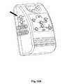
従来のエアマットレスの取扱いに関するさらなる問題は、マットレスに横たわる患者が便器を使用する必要があるときに発生する。従来のエアマットレスは、患者の臀部の位置に対応する幾つかの着脱自在なエアセルを有する。後でさらに詳しく述べる現状技術に係るマットレスを図11Aに提示する。着脱自在のエアセルを取り外して凹部を形成すると、便器を使用するために凹部に差し込むことが可能になる。しかし、二次感染を防止し、かつ簡単に清掃するために、従来のエアマットレスは、エアセルを被覆する上部ベッドスプレッドを有する。したがって、着脱自在のエアセルを取り外す前に、上部ベッドスプレッドを取り外す必要がある。上部ベッドスプレッドを取り外すには、従来のエアマットレスに横たわる患者を移動させることが依然として必要である。着脱自在のエアセルの設計は、患者が依然として従来のエアマットレスを離れる必要があるので、介護者にとって不便である。さらに、患者を移動させ、上部ベッドスプレッドを取り外すには、2人以上の個人が必要である。これは時間および人的資源の非効率的な使用であり、着脱自在のエアセルは、当初の設計で期待された通りには機能しない。 A further problem with the handling of conventional air mattresses occurs when a patient lying on the mattress needs to use a toilet. Conventional air mattresses have several removable air cells that correspond to the position of the patient's buttocks. A mattress according to the state of the art, described in more detail later, is presented in FIG. 11A. When the detachable air cell is removed to form the recess, the toilet can be inserted into the recess for use. However, in order to prevent secondary infections and easy cleaning, conventional air mattresses have an upper bed spread that covers the air cells. Therefore, it is necessary to remove the upper bed spread before removing the removable air cell. To remove the upper bed spread, it is still necessary to move the patient lying on a conventional air mattress. The removable air cell design is inconvenient for the caregiver because the patient still needs to leave the traditional air mattress. In addition, two or more individuals are required to move the patient and remove the upper bed spread. This is an inefficient use of time and human resources, and the removable air cell does not function as expected in the original design.
本発明の目的は、取扱いが改善され、患者の移動を支援する可能性および上述の不適切さを緩和または解消する可能性が改善された、医療用エアマットレスを提供することである。 It is an object of the present invention to provide a medical air mattress with improved handling and improved possibilities for assisting patient movement and mitigating or eliminating the aforementioned inadequacies.
この問題は、請求項1、5、6、11、12、および20に係る医療用エアマットレスによって解決される。したがって、ポンプおよび/またはエアセルに接続された管路は、エアセルの膨張および/または収縮を選択的に制御するように適応される。これに関して、「選択的に」とは、選択されたエアセルまたは一群の選択されたエアセルが、残りのエアセルを膨張および/または収縮することなく、すなわち1つ以上の選択されなかったエアセルを膨張および/または収縮することなく、独立して膨張および/または収縮することができることを意味する。 This problem is solved by the medical air mattress according to
本発明に係る問題はさらに、請求項32に係る医療用エアマットレスを膨張および/または収縮させるための方法、請求項33に係る医療用エアマットレスの表面を傾斜させる方法、および請求項36に係る容器を受容するための位置を医療用エアマットレスに生成する方法によって解決される。本発明の好適な実施形態を従属請求項に提示する。 The problem according to the invention further relates to a method for inflating and / or deflating a medical air mattress according to
医療用エアマットレスの支持面に動きを生じるために、かつマットレスの表面を傾斜させるために、エアセル列の奇数位置のエアセルにポンプを接続する奇数身体管路、およびエアセル列の偶数位置のエアセルにポンプを接続する偶数身体管路を、医療用エアマットレスに設けることを提案する。 In order to cause movement on the support surface of the medical air mattress and to tilt the surface of the mattress, an odd body line connecting the pump to the air cell in the odd position of the air cell row and an air cell in the even position of the air cell row It is proposed to provide an even body line connecting the pump to the medical air mattress.
医療用エアマットレスの取扱いを改善するために、本発明に係る医療用エアマットレスの一部または全部の構成部品を非常に迅速に、例えば医療的緊急事態の場合、急速放出弁によって、収縮することを提案する。急速放出弁は管路に、好ましくは奇数身体管路および偶数身体管路に接続することができる。 In order to improve the handling of medical air mattresses, some or all of the components of the medical air mattress according to the invention can be deflated very quickly, for example in the case of a medical emergency, by a quick release valve. Propose. The quick release valve can be connected to a line, preferably an odd body line and an even body line.
本発明に係る医療用エアマットレスの複数の傾斜モードをもたらすために、追加の傾斜提供エアセルが設けられる。傾斜提供エアセルは、下部ベッドスプレッドの2つの長手方向側部付近に、かつ互いに略平行に、好ましくはマットレス体が傾斜提供エアセルを跨いで取り付けられるように、下部ベッドスプレッドに長手方向に取り付けられる。したがって、患者を動かすために、マットレスの表面の傾斜は、独立して、すなわちマットレスの他のエアセルを膨張および/または収縮させることなく、傾斜提供エアセルを膨張/収縮させることによって(追加的に)修正することができる。 To provide a plurality of tilt modes of the medical air mattress according to the present invention, an additional tilt providing air cell is provided. The inclined providing air cell is attached to the lower bed spread longitudinally near the two longitudinal sides of the lower bed spread and substantially parallel to each other, preferably so that the mattress body is mounted across the inclined providing air cell. Thus, in order to move the patient, the slope of the surface of the mattress is (additionally) inflated / deflated independently, ie without inflating and / or deflating other air cells of the mattress. It can be corrected.
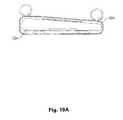
本発明のさらなる態様では、各エアセルは直径が幅広端から幅狭端まで徐々に漸減する。エアセルは幅広端を幅狭端に隣接して配設される。これは一方では、医療用エアマットレスの褥瘡防止性能を改善するので、より簡単に取り扱うことができる。他方では、徐々に漸減する身体エアセルを選択的に膨張および/または収縮させることにより、マットレスの表面を傾斜させることができる。 In a further aspect of the invention, each air cell gradually decreases in diameter from the wide end to the narrow end. The air cell is disposed with the wide end adjacent to the narrow end. This, on the other hand, improves the pressure ulcer prevention performance of the medical air mattress and is therefore easier to handle. On the other hand, the mattress surface can be tilted by selectively inflating and / or deflating the gradually declining body air cell.
本発明のさらなる態様では、ガードレールエアセルおよびガードレール管路を備えたガードレールを設ける。ガードレール管路はポンプをガードレールエアセルと接続する。医療用エアマットレスに膨張可能/収縮可能なガードレール組立体を設けることにより、患者の傷害を回避することができる。さらに、ガードレールの取扱いは、ガードレールエアセルを独立して収縮することによって除去することができるので、本発明に係る医療用エアマットレスによって簡素化される。ガードレールのそのガード位置への導入は、ガードレールエアセルを膨張させることによって行うことができる。 In a further aspect of the invention, a guardrail comprising a guardrail air cell and a guardrail conduit is provided. A guardrail line connects the pump with a guardrail air cell. By providing an inflatable / definable guardrail assembly on a medical air mattress, patient injury can be avoided. Furthermore, the handling of the guardrail is simplified by the medical air mattress according to the present invention since it can be removed by independently contracting the guardrail air cell. The introduction of the guardrail to its guard position can be performed by inflating the guardrail air cell.
医療用エアマットレスの取扱いをさらに改善するために、ガードレールスリーブが押されたときに傾かないようにするために、互いに引き合うガードレールスリーブを設けることを提案する。医療用エアマットレスはさらに、ガードレールユニットを有することができる。マットレス体を被覆する上部ベッドスプレッドは、上部ベッドスプレッドの少なくとも片側に固定された少なくとも1つのガードレールスリーブを有する。ガードレールユニットは、ガードレールスリーブにそれぞれ取り付けられた複数のガードレールエアセルを有することができる。ガードレールスリーブは上部ベッドスプレッド上に形成され、上部ベッドスプレッドおよびガードレールスリーブは、ガードレールスリーブが押されたときに所定位置に確実に留まるように、両側に互いに引き合う。したがって、ガードレールスリーブは押されたときに落下せず、その意図された目的通りに患者の最適な保護を提供し続ける。 In order to further improve the handling of medical air mattresses, it is proposed to provide guardrail sleeves that attract each other so that they do not tilt when pressed. The medical air mattress can further include a guardrail unit. The upper bed spread covering the mattress body has at least one guardrail sleeve secured to at least one side of the upper bed spread. The guardrail unit can have a plurality of guardrail air cells each attached to a guardrail sleeve. The guard rail sleeve is formed on the upper bed spread and the upper bed spread and the guard rail sleeve attract each other on both sides to ensure that they remain in place when the guard rail sleeve is pressed. Thus, the guardrail sleeve does not fall when pressed and continues to provide optimal protection for the patient according to its intended purpose.
マットレスの褥瘡防止性能のさらなる改善は、好ましくは複数の微小振動体を有する、マットレス体に取り付けられたマッサージユニットを設けることによって達成される。代替的に、または追加的に、本発明に係る医療用エアマットレスは電熱シートの形のヒートユニットを装備することができる。 Further improvement of the mattress anti- pressure ulcer performance is achieved by providing a massage unit attached to the mattress body, preferably having a plurality of microvibrators. Alternatively or additionally, the medical air mattress according to the invention can be equipped with a heat unit in the form of an electrothermal sheet.
マットレスの取扱いをさらに簡素化するため、かつ特に、患者を著しく移動させることなく、便器またはいずれかの他の種類の容器を受容するための位置を生成するために、エアセル列の中央部に独立エアセルを配設することができる。独立エアセルはポンピング組立体に接続することができる。本発明のこの態様では、マットレス体は、エアセル列と平行に配設された独立エアセルを含む複数のエアセルによって形成される。独立エアセルは、独立して収縮させるために、独立収縮ユニットに接続することができる。患者が便器を使用する必要があるときに、独立エアセルは、便器を受容するための凹部を形成するように収縮されるので、ベッドスプレッドおよび患者を移動させる必要が無い。 In order to further simplify the handling of the mattress and in particular to create a position for receiving a toilet bowl or any other kind of container without significantly moving the patient, independent of the central part of the air cell row An air cell can be provided. An independent air cell can be connected to the pumping assembly. In this aspect of the invention, the mattress body is formed by a plurality of air cells including independent air cells disposed in parallel with the air cell rows. The independent air cell can be connected to an independent contraction unit for independent contraction. When the patient needs to use the toilet bowl, the independent air cell is deflated to form a recess for receiving the toilet bowl, so there is no need to move the bed spread and the patient.
本発明の他の目的、利点、および新規の特徴は、添付の図面と併せて検討したときに以下の詳細な説明からさらに明らかになるであろう。 Other objects, advantages and novel features of the invention will become more apparent from the following detailed description when considered in conjunction with the accompanying drawings.
本発明に従って使用される上述の構成部品は、請求の範囲および実施形態の実施例に記載するものと同様、大きさ、形状、材料の選択、および技術的概念に関していかなる特別な例外的条件にもさらされず、したがって本願の技術分野で公知の選択基準を無制限に適用することができる。 The above-described components used in accordance with the present invention are subject to any special exceptional conditions with respect to size, shape, material selection, and technical concept, as described in the claims and examples of embodiments. The selection criteria known in the technical field of the present application can therefore be applied without limitation.
本発明のさらなる詳細、特徴、および利点は、従属請求項のみならず、実施例として本発明に係る幾つかの実施形態を示す関連図面の以下の説明からも得られる。 Further details, features and advantages of the invention can be derived not only from the dependent claims, but also from the following description of the relevant drawings showing several embodiments according to the invention as examples.
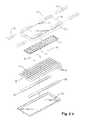
図1Aに関連して、本発明に係る医療用エアマットレスの第1実施形態は、下部ベッドスプレッド10、マットレス体30、上部ベッドスプレッド50、およびガードレールユニット(60)を備え、上部ベッドスプレッド50の各長手方向側部に2つのガードレールスリーブ52が取り付けられる。図1Bおよび図1Cによると、各ガードレールスリーブ52は、上部ベッドスプレッド50に二列または二重に縫合固定された2つのスリーブ体521を含む。図1Bは医療用エアマットレスを斜視図で示し、図1Cは、医療用エアマットレスの支持面803に横たわる患者801の右側に傾斜した医療用エアマットレスの略図を示す。 1A, a first embodiment of a medical air mattress according to the present invention includes a lower bed spread 10, a
図1Bおよび図1Cに係るガードレールの各スリーブ体521は、スリーブを上部ベッドスプレッド上にしっかりと保持するために、エアマットレス―――好ましくは交互動作エアマットレス―――のトップカバーに固定された平坦な基部800を有する。特にベッドスプレッド50に縫合することによるスリーブ52またはスリーブ体521の取付けは、例えば患者801がガードレールユニット(60)を機械的に押しあるいは変形させた場合にも、ガードレールエアセル61および/または身体エアセル31、32の空気漏れを引き起こすことが回避されるように行われる。患者801の安全性およびマットレスの取扱いはそのようにして最適化される。 Each
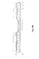
図2Aによると、複数の身体エアセル31および複数の頭部エアセル32から成るマットレス体30は、下部ベッドスプレッド10に取り付けられる。好適な実施形態では、マットレス体30は3つの頭部エアセル32を含む。各身体エアセル31および各頭部エアセル32は管状であり、かつそれぞれ直径が均一である。頭部エアセル32は身体エアセル31と同一直径を有する。身体エアセル31および頭部エアセル32は互いに平行であり、一列に配設されてエアセル列を形成する。頭部エアセル32はエアセル列の頭端部に配設される。すなわち、頭部エアセル32はエアセル列の1番目ないし3番目に配設される。身体エアセル31は、エアセル列の4番目ないし17番目に配設される。 According to FIG. 2A, a
上部ベッドスプレッド50はマットレス体30を被覆し、下部ベッドスプレッド10にしっかりと接続される。ヒートユニット51は、加熱のために上部ベッドスプレッド50の下でマットレス体30の上に設置することが好ましい。ヒートユニット51は炭素繊維電熱シートとすることができる。上部ベッドスプレッド50はガードレールスリーブ52を有する。ガードレールスリーブ52は上部ベッドスプレッド50の両方の長手方向の辺に平行に形成され、上部ベッドスプレッド50の両方の(長手方向の)辺の縁に隣接してそれぞれ形成される。好適な実施形態では、ガードレールスリーブ52は上部ベッドスプレッド50に縫合される。各ガードレールスリーブ52は少なくとも1つのスリーブ体521を有する。好適な実施形態では、各ガードレールスリーブ52は、別々に形成されかつ互いに同軸に整列した2つのスリーブ体521を有する。 The upper bed spread 50 covers the
さらに図2Aを参照すると、ガードレールエアユニット60がガードレールスリーブ52に取り付けられ、複数のガードレールエアセル61を含む。ガードレールエアセル61は、ガードレールスリーブ52のスリーブ体521内にそれぞれ取り付けられる。 Still referring to FIG. 2A, a
図2Bによると、医療用エアマットレスはさらに、マットレス体30上または内に取り付けられたマッサージユニット40を含む(図2Aも参照)。図2Bに係るマッサージユニット40は、記載の通り医療用エアマットレスの支持面803に横たわる患者801をそれぞれマッサージするために、複数の振動ユニット806または微小振動体41を含む。これらの微小振動体806、41は、マッサージを患者の頸、背中、腰、大腿などに別々にかつそれぞれ分散する。マッサージユニット40はさらに第1層804および第2層805を含むことができる。各層804、805は防水性または略防水性の材料から作成することができる。第1層804および/または第2層805の下に、複数の振動ユニット806が配置される。各振動ユニット806は振動ユニット保持バッグ807内に配置することができる。好適な実施形態では、マッサージユニット内またはその上で、加熱素子51を両方の層804、805の間に配置することができる。加熱素子51は炭素材を含むことができる。代替的に、ヒートユニット51はマットレス体30上または内に別々に、すなわち例えばマッサージユニット40無しに配置することができる。 According to FIG. 2B, the medical air mattress further includes a
図3Aに関連して、記載する医療用エアマットレスはポンピング組立体70を備える。ポンピング組立体70は身体エアセル31、頭部エアセル32、および独立エアセル23に接続され、それらを選択的に膨張させる。好適な実施形態では、図9Aに関連して、独立エアセルは、各独立エアセルの直径が一端から他端に向けて徐々に漸減し、各身体エアセルおよび各独立エアセルが幅広端および幅狭端を有するように、円錐状に形成することができる。 With reference to FIG. 3A, the medical air mattress described includes a pumping
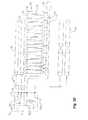
好ましくは、ポンピング組立体70は、図3Aに示す通り、ポンプ71、奇数身体管路73、偶数身体管路74、奇数独立管路54、偶数独立管路55、および急速放出弁78を含む。奇数身体管路73は、奇数身体エアセル31およびエアセル列の奇数列の頭部エアセル32にポンプ71を接続する。偶数(奇数)列とはエアセル列の偶数(奇数)位置の列を意味する。偶数身体管路74は、偶数身体エアセル31およびエアセル列の偶数列の頭部エアセル32にポンプ71を接続する。奇数独立管路54はエアセル列の奇数列の独立エアセル23にポンプ71を接続する。偶数独立管路55はエアセル列の偶数列の独立エアセル23にポンプ71を接続する。急速放出弁78は、緊急用にマットレス体30の空気を急速に放出するために、奇数身体管路73および偶数身体管路74に接続される。例えば患者が心配蘇生術(C.P.R.)を必要とする場合に、患者を即時に救助するためにマットレス体30が急速に収縮するので、記載した医療用エアマットレスを取り外す必要が無く、あるいは患者を移動させる必要が無い。これは、医療用エアマットレスの取扱いの改善に貢献する。 Preferably, the pumping
図3Aによると、ポンプ71は身体交互動作弁702に接続される。身体交互動作弁702は、ポンプ71と身体管路73、74および独立管路54、55との間に接続される。独立エアセル23は、独立して収縮される独立収縮ユニットに接続される。独立収縮ユニットは奇数電磁弁541および偶数電磁弁551を含む。奇数および偶数電磁弁541、551は三方弁であり、独立エアセル23が奇数および偶数電磁弁541、551を介して独立して選択的に収縮されるように、外部への空気抜き開口をそれぞれ有する。奇数独立管路54は奇数身体管路73を介してポンプ71に接続される。偶数独立管路55は偶数身体管路74を介してポンプ71に接続される。好適な実施形態では、奇数独立管路54は奇数独立電磁弁541を介して奇数身体管路73に接続され、偶数独立管路55は独立電磁弁551を介して偶数身体管路74に接続される。奇数身体管路73は第1逆止弁731を介して頭部エアセル32に接続される。偶数身体管路74は第2逆止弁741を介して頭部エアセル32に接続される。 According to FIG. 3A, the
図3Bに関連して、独立エアセル23のための独立収縮ユニットは、手動交互動作装置80とすることができる。使用者は手動交互動作装置80を制御して独立エアセル23の膨張を停止させる。手動交互動作装置80は空気入口、空気吹き込み開口、空気抜き出し開口、連結ロッド、2つの空気流ワッシャ、空気制限ワッシャ、および弾性要素を有する。空気入口は身体交互動作弁702に接続される。空気吹き込み開口は、独立管路54、55を介して独立エアセル23に接続される。空気抜き出し開口は外部と連通する。膨張するときは、空気抜き出し開口を閉鎖し、空気吹き込み開口を開いて独立エアセル23を膨張させる。収縮するときは、空気吹き込み開口を閉鎖し、かつ空気抜き出し開口を開くように、弾性要素、連結ロッド、および空気制限ワッシャを手動で移動させる。次いで独立エアセル23は独立して収縮される。 With reference to FIG. 3B, the independent contraction unit for the
こうして、本発明では、医療用エアマットレスの衛生面が改善されるので、エアマットレスの取扱いが向上する。例えば図11Aに係る現状技術に見られるようなマットレスの着脱自在部を使用するために、マットレスのトップカバーを取り外す必要がもはや無くなる。 Thus, according to the present invention, the hygiene aspect of the medical air mattress is improved, so that the handling of the air mattress is improved. For example, it is no longer necessary to remove the top cover of the mattress in order to use the removable portion of the mattress as found in the state of the art according to FIG. 11A.
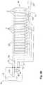
図3Cに関連して、記載する医療用エアマットレスはポンピング組立体70を備える。ポンピング組立体70は傾斜提供エアセル20、身体エアセル31、頭部エアセル32、およびガードレールエアセル61に接続され、それらを選択的に膨張させる。好適な実施形態では、ポンピング組立体70はポンプ71、傾斜提供管路72、奇数身体管路73、偶数身体管路74、ガードレール管路77、および急速放出弁78を含む。傾斜提供管路72はポンプ71を傾斜提供エアセル20に接続する。奇数身体管路73は、ポンプ71をエアセル列の奇数位置の身体エアセル31および頭部エアセル32に接続する。偶数身体管路74は、ポンプ71をエアセル列の偶数位置の身体エアセル31および頭部エアセル32に接続する。ガードレール管路77はポンプ71をガードレールエアセル61に接続する。急速放出弁78は、緊急用にマットレス体30の空気を急速に放出するために、奇数身体管路73および偶数身体管路74に接続される。例えば患者がC.P.R.を必要とする場合に、患者を即時に救助するためにマットレス体30およびガードレール組立体が急速に収縮するので、記載した医療用エアマットレスおよびガードレール組立体を取り外す必要が無く、あるいは患者を移動させる必要が無い。 With reference to FIG. 3C, the medical air mattress described includes a pumping
図3Cによると、ポンプ71は傾斜提供交互動作弁701および身体交互動作弁702に接続される。傾斜提供電磁弁703も傾斜提供交互動作弁701とポンプ71との間に接続される。傾斜提供交互動作弁701は傾斜提供電磁弁703と傾斜提供管路72との間に接続される。身体交互動作弁702は、ポンプ71と身体管路73、74およびガードレール管路77との間に接続される。ガードレール管路77はガードレール電磁弁772を介して身体交互動作弁702に接続される。奇数身体管路73は逆止弁731を介して頭部エアセル32に接続される。偶数身体管路74は逆止弁741を介して頭部エアセル32に接続される。身体交互動作弁702は逆止弁771を介してガードレール電磁弁772に接続される。 According to FIG. 3C, the
図3Dに関連して、ガードレールエアセル61のための収縮ユニットは手動交互動作装置772Aとすることができる。使用者は手動交互動作装置772Aを制御してガードレールエアセル61の膨張を停止させる。手動交互動作装置772Aは空気入口、空気吹き込み開口、空気抜き出し開口、連結ロッド、1つ以上の空気流ワッシャ、空気制限ワッシャ、および弾性要素を有する。空気入口は身体交互動作弁702に接続される。空気吹き込み開口はガードレール管路77を介してガードレールエアセル61に接続される。空気抜き出し開口は外部に連通する。膨張するときは、空気抜き出し開口を閉鎖し、空気吹き込み開口を開いてガードレールエアセル61を膨張させる。収縮するときは、空気吹き込み開口を閉鎖し、かつ空気抜き出し開口を開くように、弾性要素、連結ロッド、および空気制限ワッシャを手動で移動させる。次いでガードレールエアセル61は独立して収縮される。 With reference to FIG. 3D, the retracting unit for the
図3Aおよび図3Bに記載した医療用エアマットレスが作動すると、ポンプ71、交互動作弁702、および電磁弁541、551が起動してエアセルを膨張させ、かつ膨張を交互に調整する。膨張および収縮動作については以下で詳述する。 When the medical air mattress described in FIGS. 3A and 3B is activated, the
図3Aおよび図3Bに係るマットレス体の場合、ポンプ71が作動しているときに、使用者は様々なモードを選択することができる。 In the case of the mattress body according to FIGS. 3A and 3B, when the
完全膨張モード:図3Aおよび図3Bに関連して、ポンプ71は、身体エアセル31、頭部エアセル32、および独立エアセル23を膨張させるように作動する。 Full inflation mode: With reference to FIGS. 3A and 3B, pump 71 operates to inflate
交互動作膨張モード:図3Aおよび図3Bに関連して、ポンプ71は作動して、エアセル列の奇数または偶数列の身体エアセル31および独立エアセル23を交互に膨張させる。好適な実施形態では、身体交互動作弁702が交互動作膨張を達成する。ポンプ71は身体交互動作弁702内に空気を供給する。身体交互動作弁702は、奇数または偶数身体管路73、74に空気を交互に供給する。奇数身体管路73が膨張すると、図5に示すように、エアセル列の奇数列の身体エアセル31および独立エアセル23は膨張し、エアセル列の偶数列の身体エアセル31および独立エアセル23は収縮する。偶数身体管路74が膨張すると、図6に示すように、エアセル列の偶数位置の身体エアセル31および独立エアセル23は膨張し、エアセル列の奇数位置の身体エアセル31および独立エアセル23は収縮する。さらに、頭部エアセル32と奇数および偶数身体管路73、74との間に逆止弁731、741が接続されるので、頭部エアセル32は、身体交互動作弁702によって収縮されることなく、膨張した状態を維持して患者の頭部を安定的に支持する。 Alternating Inflation Mode: With reference to FIGS. 3A and 3B, pump 71 operates to alternately inflate
図3Aおよび図3Bに示す独立エアセル23の場合、使用者は、独立エアセル23の膨張を独立して停止させることができる。好適な実施形態では、奇数電磁弁541および偶数電磁弁551は、独立エアセル23の膨張を停止するために使用される。各電磁弁541、551は空気入口、空気吹き込み開口、および空気抜き出し開口を有する。空気入口は身体交互動作弁702に接続される。空気吹き込み開口は独立管路54、55を介して独立エアセル23に接続される。空気抜き出し開口は外部に接続される。独立エアセル23を膨張させるときに、空気抜き出し開口は閉鎖され、空気吹き込み開口は開く。独立エアセル23を独立して収縮させるときに、空気吹き込み開口は閉鎖され、空気抜き出し開口は開く。独立エアセル23が収縮したときに、独立エアセル23に対応する上部ベッドスプレッド50の中央部は支持されない。必要な場合、上部ベッドスプレッド50の中央部を陥凹させて、便器を受容するための空間または場所を形成することができる。したがって、記載する医療用エアマットレスの支持面803に横たわる患者801は移動する必要が無く、かつ記載する医療用エアマットレスに横たわったままで便器を使用することができる。 In the case of the
図3Cおよび図3Dに記載した医療用エアマットレスが作動すると、ポンプ71、交互動作弁、および電磁弁が起動してエアセルを膨張させ、かつ膨張を調整する。膨張および収縮動作については以下で詳述する。 When the medical air mattress described in FIGS. 3C and 3D is activated, the
ガードレールエアセル61の場合、ポンプ71が作動すると、ガードレールエアセル61が膨張して、上部ベッドスプレッド50に側部保護をもたらすように、ガードレールスリーブ52を展開させる。ガードレールスリーブ52は上部ベッドスプレッド50の両側に形成されるので、上部ベッドスプレッド50に横たわる患者801が偶発的にガードレールスリーブ52を押圧したときに、両側のガードレールスリーブ52は相互に引き合う。引く力は、ガードレールスリーブ52の形状を、たとえ押圧されても維持し続ける。したがって、ガードレールスリーブ52は、記載する医療用エアマットレスに横たわる患者を保護するように、所定の位置に維持される。さらに、逆止弁771は、身体交互動作弁702が動作するときに、空気が逆流することを防止する。 In the case of the
図3Cおよび図3Dに示す実施形態に係るマットレス体の場合、ポンプ71が作動しているときに、使用者は様々なモードを選択することができる。 In the case of the mattress body according to the embodiment shown in FIGS. 3C and 3D, when the
完全膨張モード:図3Cおよび図3Dに関連して、ポンプ71は、身体エアセル31および頭部エアセル32を膨張させるように動作する。マットレス体の全てのエアセルが膨張している状態を図4に示す。 Full inflation mode: With reference to FIGS. 3C and 3D, pump 71 operates to inflate
交互動作膨張モード:図3Cおよび図3Dに関連して、ポンプ71は作動して、エアセル列の奇数または偶数列の身体エアセル31を交互に膨張させる。好適な実施形態では、身体交互動作弁702が交互動作膨張を達成する。ポンプ71は身体交互動作弁702内に空気を供給する。身体交互動作弁702は奇数または偶数身体管路73、74に空気を交互に供給する。奇数身体管路73が膨張すると、図5に示すように、エアセル列の奇数位置の身体エアセル31は膨張し、エアセル列の偶数位置の身体エアセル31は収縮する。偶数身体管路74が膨張すると、図6に示すように、エアセル列の偶数列の身体エアセル31は膨張し、エアセル列の奇数列の身体エアセル31は収縮する。さらに、頭部エアセル32と奇数および偶数身体管路73、74との間に逆止弁731、741が接続されるので、頭部エアセル32は、身体交互動作弁702によって収縮されることなく、膨張した状態を維持して患者の頭部を安定的に支持する。 Alternate motion inflation mode: With reference to FIGS. 3C and 3D, the
図3Cおよび図7Cに示す傾斜提供エアセル20の場合、ポンプ71は作動して傾斜提供エアセル20の1つを膨張させ、患者が容易に寝返りを打てるように、記載する医療用エアマットレスの片側を傾斜させる。好適な実施形態では、傾斜提供交互動作弁701は傾斜提供エアセル20を交互に膨張させるように作動する。 In the case of the tilt providing
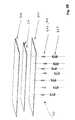
図8、図9A、および図9Bに関連して、本発明に係る医療用エアマットレスの第2実施形態を記載する。図8に係る身体マットレス30Aの身体エアセル31Aは円錐形である。円錐形のマットレス体を持つエアマットレスの端面図を図7Aおよび図7Bに示す。各身体エアセル31Aは直径が、各身体エアセル31Aが幅広端および幅狭端を有するように、一端から他端に向けて徐々に漸減する。身体エアセル31Aは幅広端を幅狭端に隣接して配設される。例えば、エアセル列の奇数位置の身体エアセル31Aの幅広端は、エアセル列の偶数位置の身体エアセル31Aの幅狭端と整列する。記載する医療用エアマットレスはさらに、医療用エアマットレスの面積を拡大し、かつ上部ベッドスプレッド50Aを支持するために、長手方向に取り付けられかつマットレス体30Aの両側にそれぞれ取り付けられた2つのオフセットエアセル34Aを備える。オフセットエアセル34Aは頭部エアセル32Aにつながる管路に接続され、また膨張を維持するように逆止弁731、741によって保護される。 A second embodiment of a medical air mattress according to the present invention will be described with reference to FIGS. 8, 9A, and 9B. The
図8に記載した医療用エアマットレスが作動すると、ポンプ71A、交互動作弁、および電磁弁も起動して、エアセルを膨張させ、かつ膨張を交互に調整する。ほとんどの動作は上述したので、図8に係る医療用エアマットレスの実施形態については、異なる動作だけを以下に記載する。マットレス体30Aの場合、ポンプ71Aが作動しているときに、使用者は様々なモードを選択することができる。 When the medical air mattress described in FIG. 8 is activated, the
完全膨張モード:ポンプ71Aは、全ての身体エアセル31Aおよび頭部エアセル32Aを膨張させるように作動する。 Full expansion mode:
交互動作膨張モード:図9A、図9B、および図10Aないし図10Fに関連して、ポンプ71Aは作動し、エアセル列の奇数または偶数列の身体エアセル31Aを交互に膨張させる。エアセル列の奇数列の身体エアセル31Aが膨張するときに、図10Aに示すようにエアセル列の偶数列の身体エアセル31Aは収縮する。エアセル列の奇数位置の身体エアセル31Aは幅広の左端および幅狭の右端を有するので、マットレス体30Aは左側が高く、右側が低くなり、患者が右側に傾斜する。エアセル列の偶数列の身体エアセル31Aが膨張するときに、図10Bに示すようにエアセル列の奇数列の身体エアセル31Aは収縮する。エアセル列の偶数位置の身体エアセル31Aは幅広の右端および幅狭の左端を有するので、マットレス体30Aは右側が高く、左側が低くなり、患者が左側に傾斜する。したがって、身体エアセル31Aの交互動作膨張は、マットレス体30Aの交互動作波動をもたらすだけでなく、患者をも特定の傾斜角度に傾斜させる。この実施形態では、身体エアセル31Aは例えば10度または略10度の傾斜角度をもたらす。これに関連して「略」とは、傾斜角度が所与の角度より数度小さくまたは大きくてもよいことを意味する。 Alternate motion inflation mode: With reference to FIGS. 9A, 9B, and 10A-10F, pump 71A operates to alternately inflate
図9A、図9B、および図10Cないし図10Eに関連して、傾斜提供エアセル20Aに関連付けられる身体エアセル31Aの交互動作膨張は、さらに異なる傾斜角度を提供する。 With reference to FIGS. 9A, 9B, and 10C-10E, the alternating inflation of the
図12に示すように、身体エアセル31Aが全部膨張し、傾斜提供エアセル20Aの1つが膨張しているときに、上部ベッドスプレッド50Aの頂面は、例えば20度または略20度の傾斜角度をもたらすように片側に傾斜する。 As shown in FIG. 12, when the
エアセル列の偶数位置の身体エアセル31Aが膨張し、エアセル列の奇数位置の身体エアセル31Aが収縮しているときに、右側の傾斜提供エアセル20Aも同時に膨張すると、全部加算して例えば30度または略30度の傾斜角度がもたらされる。 When the
エアセル列の奇数列の身体エアセル31Aが膨張し、エアセル列の偶数位置の身体エアセル31Aが収縮しているときに、左側の傾斜提供エアセル20Aも膨張すると、例えば30度または略30度の傾斜角度がもたらされる。 When the
上述した医療用エアマットレスの傾斜状態の概要、および複数の角度による患者の傾斜または回転の可能性を図10Fに示す。図10Fの図形部分は、上述した医療用エアマットレスを膨張/収縮する方法に関連する。エアセルは選択的に膨張および/または収縮される。全ての偶数エアセルまたは全ての奇数エアセルが膨張または収縮するように、あるいは全ての偶数および奇数エアセルが膨張するように、偶数および/または奇数エアセルは別々に膨張および/または収縮される。傾斜提供エアセルならびに/または偶数身体セルならびに/または奇数身体セルならびに/または偶数および奇数身体セルを選択的に膨張および/または収縮させることにより、少なくとも3つの傾斜角度が達成される。 FIG. 10F shows an overview of the tilt state of the medical air mattress described above and the possibility of patient tilt or rotation by multiple angles. The graphical portion of FIG. 10F relates to the method for inflating / deflating the medical air mattress described above. The air cell is selectively expanded and / or deflated. Even and / or odd air cells are expanded and / or deflated separately such that all even air cells or all odd air cells expand or contract, or all even and odd air cells expand. By selectively inflating and / or deflating the tilt providing air cell and / or the even body cell and / or the odd body cell and / or the even and odd body cell, at least three tilt angles are achieved.
図10Fの図形部分(a)および(b)では、偶数または奇数身体エアセル32のいずれかが膨張する。傾斜提供エアセル20は両方とも収縮する。この状態で、表面は第1小角度に、例えば10度または略10度に傾斜する。In graphic portions (a) and (b) ofFIG. 10F, either even or odd
図10Fの図形部分(c)および(d)では、マットレス体(30、30A)の右側または左側いずれかの傾斜提供エアセル(20、20A)が膨張する。偶数および奇数身体エアセル(31、31A、32、32A、23、23A)も両方とも膨張するので、図形部分(c)および(d)に係る傾斜角度は図形部分(a)および(b)の場合より大きく、例えば略20度になる。In the graphic portions (c) and (d) ofFIG. 10F, either the right or left side of the mattress body (30, 30A) is provided with an inclined air cell (20, 20A). Since both the even and odd body air cells (31, 31A, 32, 32A, 23, 23A) are also inflated, the inclination angles according to the graphic parts (c) and (d) are for the graphic parts (a) and (b). It is larger, for example, approximately 20 degrees.
図10Fの図形部分(e)および(f)では、偶数または奇数身体エアセル(31、31A、32、32A、23、23A)が膨張し、傾斜提供エアセル(20、20A)の1つも同時に膨張する。したがって、総傾斜角度はさらに大きく、例えば略30度になる。In graphic portions (e) and (f) ofFIG. 10F , even or odd body air cells (31, 31A, 32, 32A, 23, 23A) are inflated, and one of the tilt providing air cells (20, 20A) is inflated simultaneously. . Therefore, the total inclination angle is even larger, for example, approximately 30 degrees.
医療用エアマットレスの全ての状態は、図12および図12Bに示す制御装置によって制御することができる。制御装置は、例えば図3Aないし図3D、図9Aおよび図9Bに示す、ポンピング組立体および医療用エアマットレスの全ての弁に接続される。ほとんどの状態は、制御装置のワンタッチ操作により処理することができる。特に、便器のような容器を受容する空間のあるマットレスの中央部分を設けるためのガードレール、マットレスを傾斜させるときに係合されるセル、または独立エアセルの膨張/収縮は、片手で、または制御装置のワンタッチ操作で制御することができる。これらの機能および状態は全て、制御装置の1つのボタンを押すだけで操作することができる。 All states of the medical air mattress can be controlled by the control device shown in FIGS. 12 and 12B. The control device is connected to all valves of the pumping assembly and medical air mattress, for example shown in FIGS. 3A-3D, 9A and 9B. Most states can be handled by one-touch operation of the control device. In particular, a guardrail for providing a central portion of a mattress with a space for receiving a container such as a toilet bowl, a cell engaged when the mattress is tilted, or an independent air cell can be inflated / deflated with one hand or a control device It can be controlled by one-touch operation. All of these functions and states can be operated with the push of a single button on the control device.
本発明に係る医療用エアマットレスは多くの利点を有する。上部ベッドスプレッド50の上に形成されるガードレールスリーブ52により、上部ベッドスプレッド50の2つの対向する側部からガードレールスリーブ52間で相互に引き合う力は、ガードレールスリーブ52を、医療用エアマットレスに横たわる患者801を保護する所定の位置に維持させる。さらに、傾斜提供エアセル20Aに関連付けられる円錐形の身体エアセル31Aは、複数の傾斜角度をもたらす。したがって、様々な患者が、患者に必要なまたは医師に指示された適切な傾斜角度を選択することができる。 The medical air mattress according to the present invention has many advantages. Due to the
図2A、図2B、および図8を参照すると、ヒートユニット51がマットレス体に取り付けられる。それは、上部ベッドスプレッドを加熱するために上部ベッドスプレッド50の下に配置することが好ましい。ヒートユニット51は炭素繊維電熱シートとすることができる。ヒートユニット51は、図2Bに示す加熱およびマッサージユニットの構成部品または一体的部品とすることができる。 2A, 2B, and 8, the
独立エアセル23を持つ医療用エアマットレスを図11Bに示す。図11Bでは、エアマットレスの側面図が示される。身体エアセル31および頭部エアセル32が膨張している。独立エアセル23は収縮しているので、マットレス体30の中央領域に、トイレットまたは便器のような容器を受容する位置が生成される。容器を受容するための位置は略円錐形を有することができる。独立エアセル23の膨張または収縮は、図12A/Bに係る制御装置により制御することができる。便器を受容するための凹状位置を生成することによって、現状技術(図11A参照)に係るマットレス体の一部を例えば取り外す必要がもはや無くなる。 A medical air mattress having an
図12A/Bでは、医療用エアマットレスの制御装置は、1つのボタンに触れるだけでエアマットレスの幾つかの機能を制御することができるように構成される。ガードレールユニットの膨張/収縮は、ガードレール機能のためのワンタッチボタンにより制御することができる(図12Aの矢印を参照)。ワンタッチボタンとは、ボタンを1回触れることにより、マットレスの関連機能を可能または無効にすることを意味する。独立エアセル23の膨張/収縮は、トイレット機能のワンタッチボタンにより制御することができる。マットレス表面の様々な角度の傾斜は、傾斜機能のためのワンタッチボタン(ピッチ、図12Bの矢印を参照)により制御することができる。「ピッチ」ボタンに触れると、上述した方法に従ってマットレス表面の角度が増加または減少する。(身体および/または頭部)エアセルの膨張の交互動作は、静止/交互動作機能のためのワンタッチボタンにより制御することができる。マットレスの加熱は、加熱機能のためのワンタッチボタンにより制御することができる。マットレスのマッサージユニットは、マッサージ機能のワンタッチボタンにより制御することができる。図12A/Bに係る制御装置は、医療スタッフまたは患者自身が操作することができるように、マットレス体の近くに配置することができる。 In FIGS. 12A / B, the medical air mattress controller is configured to control several functions of the air mattress with the touch of a single button. The expansion / contraction of the guardrail unit can be controlled by a one-touch button for the guardrail function (see arrow in FIG. 12A). A one-touch button means enabling or disabling related functions of the mattress by touching the button once. Expansion / contraction of the
本発明の構造および特徴の詳細と共に、本発明の多くの特徴および利点を上記の説明に記載したが、上記の開示は単なる例証にすぎない。細部について、特に部品の形状、大きさ、および配列に関して、本発明の原則内で、添付する請求項に表明される用語の広い一般的な意味によって示される最大限の範囲まで、変更を加えることができる。 Although many features and advantages of the present invention, as well as details of the structure and features of the invention, have been described in the foregoing description, the above disclosure is merely illustrative. Make changes within the principles of the invention to the fullest extent indicated by the broad general meaning of the terms expressed in the appended claims, with regard to details, in particular with regard to the shape, size and arrangement of the parts. Can do.
10 下部ベッドスプレッド
20 傾斜提供エアセル
23 独立エアセル
30、30A マットレス体
31、31A 身体エアセル
32、32A 頭部エアセル
34A オフセットエアセル
40 マッサージユニット
41 微小振動体
50、50A 上部ベッドスプレッド
51 ヒートユニット
52 ガードレールスリーブ
54 奇数独立管路
55 偶数独立管路
60 ガードレールユニット
61 ガードレールエアセル
70 ポンピング組立体
71、71A ポンプ
72 傾斜提供管路
73 奇数身体管路
74 偶数身体管路
77 ガードレール管路
78 急速放出弁
80 手動交互動作装置
521 スリーブ体
541 奇数電磁弁
551 偶数電磁弁
701 傾斜提供交互動作弁
702 身体交互動作弁
703 傾斜提供電磁弁
731 第1逆止弁
741 第2逆止弁
771 第3逆止弁
772 ガードレール電磁弁
772A 手動交互動作装置
800 基部
801 患者
803 支持面
804 第1層
805 第2層
806 振動ユニット
807 保持バッグ10 Lower bed spread 20
Claims (21)
Translated fromJapanese前記下部ベッドスプレッド(10)に取り付けられたマットレス体(30)であって、互いに略平行でありかつ一列に配設されてエアセル列を形成する複数の身体エアセル(31)および複数の頭部エアセル(32)を含むマットレス体(30)と、
前記下部ベッドスプレッド(10)に接続され、前記マットレス体(30)を被覆する上部ベッドスプレッド(50)と、
前記上部ベッドスプレッド(50)の両側においてその長手方向縁部に隣接してそれぞれ形成された、ガードレールエアセル(61)を有するガードレールと、
ポンプ(71)、および前記ポンプ(71)を前記エアセル(31,32,61)に接続する管路(73,74,77)を含むポンピング組立体(70)と、
を備え、
前記管路は、前記ポンプ(71)に接続されたガードレール管路(77)を含むとともに、前記ポンプ(71)を前記身体エアセル(31)、前記頭部エアセル(32)および前記ガードレールエアセル(61)に接続して、これらエアセルの膨張および/または収縮を選択的に制御するするように構成されており、
前記上部ベッドスプレッド(50)の両側における前記各ガードレールは、別々に形成され互いに同軸に整列するとともに、個別の前記ガードレールエアセル(61)を収容する2つのスリーブ体(521)を有しており、
前記各スリーブ体(521)は、二重縫合線によりかつ前記上部ベッドスプレッドの表面に直接固定された平坦な基部(800)を有する、ことを特徴とする、医療用エアマットレス。Lower bed spread (10),
The lower bedspreads (10) attached mattress body (30) comprising a plurality of bodily air cells (31)and the numbermultiple of forming the air cells columns are arranged is and in a row substantially parallel to each other A mattress body (30) including a head air cell (32);
Wherein it isconnected to the lower bedspreads (10), an upper bed spread (50) for covering the mattress body (30),
Guardrails having guardrail air cells (61) formed on both sides of the upper bed spread (50), respectively, adjacent to the longitudinal edges thereof;
A pump(71), and the pumping assembly (70) comprisinga pump (71)Rukanro be connected to the air cells(31,32,61) and(73,74,77),
With
The conduitincludes a guardrail conduit (77) connected to the pump (71), and the pump (71) is connected to thebody air cell(31), the head air cell (32), and the guardrail air cell (61). ) And is configured to selectively control the expansion and / or contraction ofthese air cells,
Each of the guardrails on both sides of the upper bed spread (50) has two sleeve bodies (521) that are separately formed and aligned coaxially with each other and that house the individual guardrail air cells (61),
Medical air mattress,wherein each sleeve body (521) has a flat base (800) secured to the surface of the upper bed spread by a double suture .
前記ポンプ(71)と身体管路(73、74)およびガードレール管路(77)との間に接続された身体交互動作弁(702)と、
前記奇数身体管路(73)と前記エアセル列の奇数位置の頭部エアセル(32)との間に接続された第1逆止弁(731)と、
前記偶数身体管路74と前記エアセル列の偶数位置の頭部エアセル(32)との間に接続された第2逆止弁(741)と、
を含むことを特徴とする、請求項2に記載の医療用エアマットレス。The pumping assembly (70) further includes:
An alternating body valve (702) connected between the pump (71) and body lines (73, 74) and guardrail lines (77);
A first check valve (731) connected between the odd body conduit (73) and a head air cell (32) at an odd position in the air cell row;
A second check valve (741) connected between the even body line 74 and a head air cell (32) at an even position in the air cell row;
The medical air mattress accordingto claim2, comprising:
前記身体交互動作弁(702)と前記ガードレール管路(77)との間に接続されたガードレール電磁弁(772)、および
前記身体交互動作弁(702)と前記ガードレール電磁弁(772)との間に取り付けられた第3逆止弁(771)、
を含むことを特徴とする、請求項9に記載の医療用エアマットレス。The pumping assembly (70) further includes:
A guardrail solenoid valve (772) connected between the body alternating action valve (702) and the guardrail conduit (77); and between the body alternating action valve (702) and the guardrail solenoid valve (772). the third check valve attached to the(771),
Characterized in that it comprisesa medical air mattress of claim9.
前記身体交互動作弁(702)と前記ガードレール管路(77)との間に接続された手動交互動作装置と、
前記身体交互動作弁(702)と前記手動交互動作装置との間に取り付けられた第3逆止弁(771)と、
を含むことを特徴とする、請求項1ないし9のいずれかに記載の医療用エアマットレス。The pumping assembly (70) further includes:
A manual alternating device connected between the body alternating valve (702) and the guardrail line (77);
A third check valve (771) mounted between the body alternating valve (702) and the manual alternating device;
Characterized in that it comprises a medical air mattress according to any one of claims 1 to9.
前記ポンプ(71)を前記エアセル列の奇数位置の独立エアセル(23)に接続する奇数独立管路(54)と、
前記ポンプ(71)を前記エアセル列の偶数位置の独立エアセル(23)に接続する偶数独立管路(55)と、
を含むことを特徴とする、請求項13ないし17のいずれかに記載の医療用エアマットレス。The pumping assembly (70) further includes:
Odd-number independent pipes (54) connecting the pump (71) to the independent air cells (23) in odd-numbered positions of the air cell row;
An even independent line (55) connecting the pump (71) to an independent air cell (23) at an even position in the air cell row;
The medical air mattress according to any one of claims13 to17 , characterized by comprising:
Applications Claiming Priority (5)
| Application Number | Priority Date | Filing Date | Title |
|---|---|---|---|
| EP11170166.0AEP2535029B8 (en) | 2011-06-16 | 2011-06-16 | Medical air mattress |
| EP11170191.8 | 2011-06-16 | ||
| EP11170166.0 | 2011-06-16 | ||
| EP11170191.8AEP2535030B1 (en) | 2011-06-14 | 2011-06-16 | Medical air mattress |
| PCT/IB2012/001202WO2012172421A1 (en) | 2011-06-16 | 2012-06-18 | Medical air mattress, method to inflate/deflate a medical air mattress and method to incline the bearing surface of a medical air mattress |
Publications (3)
| Publication Number | Publication Date |
|---|---|
| JP2014516737A JP2014516737A (en) | 2014-07-17 |
| JP2014516737A5 JP2014516737A5 (en) | 2015-06-25 |
| JP6050338B2true JP6050338B2 (en) | 2016-12-21 |
Family
ID=47356601
Family Applications (1)
| Application Number | Title | Priority Date | Filing Date |
|---|---|---|---|
| JP2014515303AActiveJP6050338B2 (en) | 2011-06-16 | 2012-06-18 | Medical air mattress, method for inflating / deflating medical air mattress, and method for inclining support surface of medical air mattress |
Country Status (7)
| Country | Link |
|---|---|
| US (1) | US9566202B2 (en) |
| EP (2) | EP2726047B1 (en) |
| JP (1) | JP6050338B2 (en) |
| CN (4) | CN107456339B (en) |
| ES (2) | ES2955084T3 (en) |
| RU (1) | RU2612920C2 (en) |
| WO (1) | WO2012172421A1 (en) |
Cited By (2)
| Publication number | Priority date | Publication date | Assignee | Title |
|---|---|---|---|---|
| US10143609B2 (en) | 2011-06-14 | 2018-12-04 | Picard Healthcare Technology (Dongguan) Co. Ltd. | Medical air mattress |
| USRE47680E1 (en) | 2011-06-10 | 2019-11-05 | Picard Healthcare Technology (Dongguan) Co. Ltd. | Medical air mattress |
Families Citing this family (25)
| Publication number | Priority date | Publication date | Assignee | Title |
|---|---|---|---|---|
| US9015885B2 (en)* | 2013-02-13 | 2015-04-28 | William Lawrence Chapin | Traveling wave air mattresses and method and apparatus for generating traveling waves thereon |
| CA2939545C (en)* | 2014-02-13 | 2018-11-27 | William Lawrence Chapin | Soliton traveling wave air mattresses |
| GB201402974D0 (en)* | 2014-02-20 | 2014-04-09 | Huntleigh Technology Ltd | Improvements in and relating to cell inflation of a mattress |
| GB2535342B (en)* | 2014-02-27 | 2017-02-01 | Rober Ltd | Alternating pressure mattress, system and connector |
| CN204218422U (en)* | 2014-09-26 | 2015-03-25 | 石狮市天域光电技术有限公司 | Health care air-flow cold and warm mattress |
| US9308393B1 (en) | 2015-01-15 | 2016-04-12 | Dri-Em, Inc. | Bed drying device, UV lights for bedsores |
| US10413464B2 (en) | 2015-05-05 | 2019-09-17 | Hill-Rom Services, Inc. | Multi-mode sacral unloading pressure relief in a patient support surface |
| CN104887431B (en)* | 2015-06-12 | 2017-03-22 | 上海旭旦实业有限公司 | Anti-bedsore mattress |
| US11284725B2 (en) | 2016-10-25 | 2022-03-29 | Daniel Moss | Inflatable mattress bumper system |
| US10828216B2 (en)* | 2017-03-03 | 2020-11-10 | Medline Industries, Inc. | Inflatable patient repositioning sheet |
| NL1042622B1 (en)* | 2017-11-02 | 2019-05-13 | Smart Mattress Company B V | Smart mattress with adjustable patient support. |
| CN108577350B (en)* | 2018-04-26 | 2021-11-09 | 长春财经学院 | Artificial intelligence bed based on thing networking |
| US12150905B2 (en) | 2018-11-27 | 2024-11-26 | Stryker Corporation | Patient support apparatus with notification system |
| CN109998840A (en)* | 2019-04-19 | 2019-07-12 | 安阳市第六人民医院(安阳市口腔医院) | A kind of neck of femur operation C-arm x-ray fluoroscopy and take the photograph piece operating table |
| RU2696102C1 (en)* | 2019-05-10 | 2019-07-31 | Общество с ограниченной ответственностью "Реабилитик" | Anti-decubitus mattress |
| RU2696104C1 (en)* | 2019-05-10 | 2019-07-31 | Общество с ограниченной ответственностью "Реабилитик" | Anti-decubitus mattress |
| CN211433830U (en)* | 2019-06-26 | 2020-09-08 | 博瑟姆·尼采·乌泰 | Bedsore-resistant mattress |
| CA3085438A1 (en) | 2019-08-13 | 2021-02-13 | Stryker Corporation | Support apparatus for bariatric person |
| CN111329692A (en)* | 2020-04-03 | 2020-06-26 | 四川省西部放射治疗协会 | A prone position rehabilitation mattress |
| CN112690973A (en)* | 2020-12-28 | 2021-04-23 | 西南医科大学 | Wearing formula prevents bedsore and aerifys clothes |
| CN112618208A (en)* | 2021-01-05 | 2021-04-09 | 上海应用技术大学 | Novel functional air cushion nursing bed |
| CN112869983B (en)* | 2021-03-01 | 2022-02-15 | 金华市人民医院 | Automatic turning air cushion bed and inflating method thereof |
| US11376179B1 (en)* | 2021-07-08 | 2022-07-05 | Foshan Hongfeng Medical Technology Co., Ltd | Multifunctional nursing mattress |
| CN113966933A (en)* | 2021-09-17 | 2022-01-25 | 珠海格力电器股份有限公司 | Control method and device, electronic equipment, intelligent bed and storage medium |
| TWI891574B (en) | 2024-11-22 | 2025-07-21 | 聖州企業股份有限公司 | Inflatable mattress structure with separable air column |
Family Cites Families (82)
| Publication number | Priority date | Publication date | Assignee | Title |
|---|---|---|---|---|
| US2998817A (en)* | 1959-08-07 | 1961-09-05 | Gary Armstrong Stebbins | Inflatable massaging and cooling mattress |
| GB1286197A (en)* | 1970-03-13 | 1972-08-23 | Ronald James Peter Evans | Improvements in or relating to alternating pressure pads for bed patients |
| US3653083A (en)* | 1970-05-11 | 1972-04-04 | Roy Lapidus | Bed pad |
| GB1595417A (en)* | 1977-03-29 | 1981-08-12 | Welch H G | Beds and mattresses |
| US4215446A (en)* | 1978-08-28 | 1980-08-05 | Patsie Mahoney | Padded hospital bed siderail cover |
| US4617690A (en)* | 1985-01-07 | 1986-10-21 | Whittaker Corporation | Inflatable bed patient mattress |
| US5005240A (en)* | 1987-11-20 | 1991-04-09 | Kinetics Concepts, Inc. | Patient support apparatus |
| US4953247A (en)* | 1988-05-09 | 1990-09-04 | Hasty Charles E | Air-operated body support device |
| JPH057239U (en)* | 1991-05-03 | 1993-02-02 | カツトラー スタンレイ | Pine surge device |
| US5269030A (en)* | 1991-11-13 | 1993-12-14 | Ssi Medical Services, Inc. | Apparatus and method for managing waste from patient care, maintenance, and treatment |
| JPH05228180A (en)* | 1992-05-11 | 1993-09-07 | Ebara Shinwa:Kk | Air cell used for mat for preventing bedsore |
| JPH0627139Y2 (en)* | 1992-06-30 | 1994-07-27 | ファミリー株式会社 | Air mattress equipment |
| US5267364A (en)* | 1992-08-11 | 1993-12-07 | Kinetic Concepts, Inc. | Therapeutic wave mattress |
| US5394577A (en)* | 1993-03-29 | 1995-03-07 | James; Ingrid B. | Therapeutic anti-decubitus, lateral rotation mattress |
| JPH07116199A (en)* | 1993-10-26 | 1995-05-09 | Molten Corp | Air mattress |
| US6892405B1 (en)* | 1994-05-09 | 2005-05-17 | Kci Licensing, Inc. | Therapeutic bed and related apparatus and methods |
| US5611096A (en)* | 1994-05-09 | 1997-03-18 | Kinetic Concepts, Inc. | Positional feedback system for medical mattress systems |
| US5564142A (en)* | 1995-05-11 | 1996-10-15 | Liu; Tsung-Hsi | Air mattress collaboratively cushioned with pulsative and static symbiotic sacs |
| CN2249023Y (en)* | 1995-07-18 | 1997-03-12 | 陈志强 | Multi-function health-care bed mattress |
| US5701622A (en)* | 1996-01-16 | 1997-12-30 | Sentech Medical Systems, Inc. | Pulsating operating table cushion |
| US5685036A (en)* | 1996-02-15 | 1997-11-11 | Geomarine Systems, Inc. | Alternating pressure mattress system and method |
| US5647079A (en)* | 1996-03-20 | 1997-07-15 | Hill-Rom, Inc. | Inflatable patient support surface system |
| FR2760967B1 (en)* | 1997-03-19 | 1999-08-06 | Support Systems International | METHOD AND APPARATUS FOR RAPID DEFLECTION AND SUBSTANTIALLY TOTAL EMPTYING OF AN INFLATABLE CHAMBER, IN PARTICULAR A CHAMBER OF A SUPPORT DEVICE SUCH AS A MATTRESS |
| JP3168324B2 (en)* | 1997-04-14 | 2001-05-21 | 澄宏 長谷川 | Chain lock to attach to cone |
| US5774917A (en)* | 1997-06-20 | 1998-07-07 | Liu; Antony Ching-Fong | Turn mattress inherently formed with side guards |
| US6085372A (en)* | 1997-10-31 | 2000-07-11 | James; Ingrid B. | Anti-decubitus pneumatic mattress |
| US5956787A (en)* | 1997-10-31 | 1999-09-28 | James; Ingrid B. | Anti-decubitus pneumatic mattress |
| JP3634170B2 (en)* | 1998-10-19 | 2005-03-30 | フランスベッド株式会社 | Air mattress device |
| US6370716B1 (en)* | 1999-04-20 | 2002-04-16 | John W. Wilkinson | Inflatable cushioning device with tilting apparatus |
| US6269505B1 (en)* | 1999-04-20 | 2001-08-07 | M.P.L. Ltd. | Inflatable cushioning device with manifold system |
| CN2381305Y (en)* | 1999-06-17 | 2000-06-07 | 毛相国 | Aerated mattress for hospital bed |
| GB0008399D0 (en)* | 2000-04-05 | 2000-05-24 | Huntleigh Technology Plc | Inflatable support |
| GB0020832D0 (en)* | 2000-08-24 | 2000-10-11 | Park House Ltd | Inflatable mattress system |
| JP2002136560A (en)* | 2000-10-31 | 2002-05-14 | Fuji Iryoki:Kk | Air mat apparatus |
| DK2140847T3 (en)* | 2000-11-07 | 2012-08-27 | Tempur World Llc | Therapeutic mattress device |
| US6725485B2 (en)* | 2001-01-08 | 2004-04-27 | John H. Hayes | Mattress and bedpan cushion system |
| AU2002244012A1 (en)* | 2001-02-15 | 2002-09-04 | Hill-Rom Services, Inc. | Self-inflating mattress |
| TW574918U (en)* | 2001-03-07 | 2004-02-01 | Shan Lin Heat Treat Co Ltd | Air bed with massage device |
| US6564411B2 (en)* | 2001-03-19 | 2003-05-20 | Shahzad Pirzada | Active fluid channeling system for a bed |
| US6739001B2 (en)* | 2001-04-27 | 2004-05-25 | Gaymar Industries, Inc. | Cushioning device including a restraint structure |
| US6855158B2 (en)* | 2001-09-11 | 2005-02-15 | Hill-Rom Services, Inc. | Thermo-regulating patient support structure |
| US6523198B1 (en)* | 2001-11-23 | 2003-02-25 | Barbara E. Temple | Modular medical-bed mattress with underlying bed pan |
| US6695789B2 (en)* | 2002-02-21 | 2004-02-24 | Medwave, Inc. | Disposable non-invasive blood pressure sensor |
| ATE415840T1 (en)* | 2002-02-28 | 2008-12-15 | Gaymar Ind Inc | SELF-ADJUSTING UPHOLSTERY DEVICE |
| CN1442613A (en)* | 2002-03-06 | 2003-09-17 | 桂在兴 | Adjustable and Induction Air Mattress Inflator |
| CN2552522Y (en)* | 2002-03-21 | 2003-05-28 | 郑建都 | Multifunctional medical bed-sore-preventing temp.-regulating inflatable mattress |
| US6604252B1 (en)* | 2002-05-22 | 2003-08-12 | Terry Tu | Air mattress with alternate lifting function and sideguards |
| US20040107503A1 (en)* | 2002-12-09 | 2004-06-10 | Eezcare Medical Corp. | Inflation body structure for an air mattress |
| US7322947B2 (en)* | 2003-03-26 | 2008-01-29 | Gaymar Industries, Inc. | Vibrational and pulsating cushioning device |
| US20060117488A1 (en)* | 2004-12-03 | 2006-06-08 | Hsuen-Haw Hung | Automatic massage air cushion |
| DK1850703T3 (en)* | 2005-02-14 | 2009-07-20 | Pegasus Ltd | Alternating pressure mattresses |
| US7444704B2 (en)* | 2005-02-16 | 2008-11-04 | Kci Licensing, Inc. | System and method for maintaining air inflatable mattress configuration |
| JP5166238B2 (en)* | 2005-03-28 | 2013-03-21 | ビー.ジー.インダストリーズ,インク. | Improved mattress |
| US7681269B2 (en)* | 2005-06-01 | 2010-03-23 | Anodyne Medical Device, Inc. | Support surface with integral patient turning mechanism |
| US7266852B2 (en)* | 2005-10-31 | 2007-09-11 | Woodlark Circle, Inc. | Inflatable transfer mattress |
| JP2007159981A (en)* | 2005-12-16 | 2007-06-28 | Yuko Shimada | Mat device |
| US8261387B2 (en)* | 2006-02-10 | 2012-09-11 | Joerns Llc | Self inflating air mattress |
| JP4849991B2 (en)* | 2006-08-03 | 2012-01-11 | 有限会社 健康百二十才 | Bed for bedsore prevention |
| CN200942162Y (en)* | 2006-08-18 | 2007-09-05 | 吴昌永 | Automatic urethral catheterization anti-bedsore mattress |
| CN201026282Y (en)* | 2006-10-20 | 2008-02-27 | 张继道 | Bedsore-proof air chamber bed cushion |
| CN201032957Y (en)* | 2006-11-13 | 2008-03-12 | 张荣楠 | Combined inflated mattress |
| US20080178392A1 (en)* | 2007-01-29 | 2008-07-31 | Guo Feng Chu | Air Cushion with Alternatively Inflated Chambers |
| FR2912884B1 (en)* | 2007-02-27 | 2012-09-28 | Hill Rom Ind Sa | "MATTRESS-TYPE SUPPORT DEVICE COMPRISING AT LEAST ONE SOLENOID VALVE FOR CONTROLLING THE SUPPLY / EXHAUST OF FLUID IN SUBSTRATES OF THE MATTRESS" |
| CN201019949Y (en)* | 2007-04-27 | 2008-02-13 | 贾广田 | Sideways air cushion |
| US7954186B2 (en)* | 2007-05-04 | 2011-06-07 | Gaymar Industries, Inc. | Inflatable mattress with uniform restraint |
| FR2917278A1 (en)* | 2007-06-18 | 2008-12-19 | Hill Rom Ind S A Sa | MATTRESS-TYPE SUPPORT DEVICE HAVING A HETEROGENEUS INFLATABLE STRUCTURE |
| FR2922439B1 (en)* | 2007-10-18 | 2010-12-10 | Hill Rom Ind Sa | METHOD FOR ALTERNATE INFLATION OF AN INFLATABLE CELL SUPPORT DEVICE AND DEVICE FOR IMPLEMENTING IT |
| CN101564576A (en)* | 2008-04-22 | 2009-10-28 | 韩颖 | Far-infrared medicament physical therapy mattress |
| CN101803983B (en)* | 2009-02-13 | 2012-04-11 | 上海电机学院 | Intelligent turn-over bedsore-proof air cushion |
| GB0906672D0 (en)* | 2009-04-17 | 2009-06-03 | Outram Francis W | A sleeping aid |
| US20110041246A1 (en)* | 2009-08-20 | 2011-02-24 | Hong Kong Applied Science And Technology Research Institute Co., Ltd. | Systems and methods providing temperature regulated cushion structure |
| CN201519252U (en)* | 2009-10-26 | 2010-07-07 | 祁洪霞 | Multifunctional massage pad capable of preventing local bedsore |
| CN101716113B (en)* | 2009-12-14 | 2011-08-17 | 浙江大学 | Intelligent nursing air cushion system |
| JP5558130B2 (en)* | 2010-02-05 | 2014-07-23 | パラマウントベッド株式会社 | Air mattress with built-in pump |
| JP5562060B2 (en)* | 2010-02-05 | 2014-07-30 | パラマウントベッド株式会社 | Air mattress |
| KR20110132025A (en)* | 2010-05-31 | 2011-12-07 | 주식회사 시몬스침대 | Mattress with cooling and heating function |
| CN201768107U (en)* | 2010-07-13 | 2011-03-23 | 重庆英凯美医疗器械有限公司 | Medical multifunctional anti-bedsore air cushion |
| US9101224B2 (en)* | 2011-06-10 | 2015-08-11 | Picard Healthcare Technolgy (Dongguan) Co. Ltd. | Medical air mattress |
| CN103340724B (en)* | 2011-06-16 | 2015-08-26 | 东莞沛佳医疗保健科技有限公司 | A kind of Medical air-inflated mattress |
| CN102525768B (en)* | 2011-06-16 | 2016-07-06 | 东莞沛佳医疗保健科技有限公司 | A kind of medicinal inflatable mattress |
| CN202446403U (en)* | 2011-06-16 | 2012-09-26 | 东莞沛佳医疗保健科技有限公司 | A kind of medical inflatable mattress |
| CN202478036U (en)* | 2011-06-16 | 2012-10-10 | 东莞沛佳医疗保健科技有限公司 | Air mattress for medical use |
- 2012
- 2012-06-18WOPCT/IB2012/001202patent/WO2012172421A1/enactiveApplication Filing
- 2012-06-18USUS14/125,336patent/US9566202B2/enactiveActive
- 2012-06-18RURU2014101149Apatent/RU2612920C2/enactive
- 2012-06-18CNCN201710644571.2Apatent/CN107456339B/enactiveActive
- 2012-06-18CNCN201810317895.XApatent/CN108714081B/enactiveActive
- 2012-06-18EPEP12799891.2Apatent/EP2726047B1/enactiveActive
- 2012-06-18CNCN201280029594.8Apatent/CN103717190B/enactiveActive
- 2012-06-18JPJP2014515303Apatent/JP6050338B2/enactiveActive
- 2012-06-18EPEP17205768.9Apatent/EP3329892B1/enactiveActive
- 2012-06-18ESES12799891Tpatent/ES2955084T3/enactiveActive
- 2012-06-18CNCN201810218352.2Apatent/CN108309629A/enactivePending
- 2012-06-18ESES17205768Tpatent/ES2992033T3/enactiveActive
Cited By (3)
| Publication number | Priority date | Publication date | Assignee | Title |
|---|---|---|---|---|
| USRE47680E1 (en) | 2011-06-10 | 2019-11-05 | Picard Healthcare Technology (Dongguan) Co. Ltd. | Medical air mattress |
| US10143609B2 (en) | 2011-06-14 | 2018-12-04 | Picard Healthcare Technology (Dongguan) Co. Ltd. | Medical air mattress |
| US10172754B2 (en) | 2011-06-14 | 2019-01-08 | Picard Healthcare Technology (Dongguan) Co. Ltd. | Medical air mattress |
Also Published As
| Publication number | Publication date |
|---|---|
| JP2014516737A (en) | 2014-07-17 |
| EP2726047B1 (en) | 2023-06-07 |
| CN108309629A (en) | 2018-07-24 |
| CN107456339B (en) | 2018-09-28 |
| CN103717190B (en) | 2018-04-27 |
| RU2014101149A (en) | 2015-07-27 |
| US9566202B2 (en) | 2017-02-14 |
| ES2992033T3 (en) | 2024-12-05 |
| WO2012172421A1 (en) | 2012-12-20 |
| EP3329892B1 (en) | 2024-07-17 |
| CN108714081A (en) | 2018-10-30 |
| EP2726047A1 (en) | 2014-05-07 |
| CN103717190A (en) | 2014-04-09 |
| CN108714081B (en) | 2020-07-03 |
| WO2012172421A8 (en) | 2017-04-20 |
| RU2612920C2 (en) | 2017-03-13 |
| US20140173825A1 (en) | 2014-06-26 |
| ES2955084T3 (en) | 2023-11-28 |
| EP3329892A1 (en) | 2018-06-06 |
| EP2726047A4 (en) | 2015-08-12 |
| CN107456339A (en) | 2017-12-12 |
Similar Documents
| Publication | Publication Date | Title |
|---|---|---|
| JP6050338B2 (en) | Medical air mattress, method for inflating / deflating medical air mattress, and method for inclining support surface of medical air mattress | |
| US10172754B2 (en) | Medical air mattress | |
| USRE47680E1 (en) | Medical air mattress | |
| US10064770B2 (en) | Patient turning and positioning system device | |
| US7464422B2 (en) | Inflatable device for turning people on their side and back again | |
| EP2535029B1 (en) | Medical air mattress | |
| US11389352B2 (en) | Devices and methods to help prevent decubitus ulcers | |
| JP6055580B2 (en) | Mattress for changing position | |
| TW201231035A (en) | Inflatable mattress for medical use | |
| WO1997017930A1 (en) | Anti-decubitus medical bed | |
| CN202446403U (en) | A kind of medical inflatable mattress | |
| CN105796268A (en) | Inflatable mattress capable of facilitating defecation and preventing bedsores | |
| WO2015171078A1 (en) | Apparatus and method for assisting body movement | |
| CN215132067U (en) | a medical nursing pad | |
| JPH0866435A (en) | Care device unit | |
| CN107928925A (en) | The pneumatic pillow bridge of counteracting bedsores |
Legal Events
| Date | Code | Title | Description |
|---|---|---|---|
| A521 | Request for written amendment filed | Free format text:JAPANESE INTERMEDIATE CODE: A523 Effective date:20150508 | |
| A621 | Written request for application examination | Free format text:JAPANESE INTERMEDIATE CODE: A621 Effective date:20150508 | |
| A977 | Report on retrieval | Free format text:JAPANESE INTERMEDIATE CODE: A971007 Effective date:20160314 | |
| A131 | Notification of reasons for refusal | Free format text:JAPANESE INTERMEDIATE CODE: A131 Effective date:20160322 | |
| A601 | Written request for extension of time | Free format text:JAPANESE INTERMEDIATE CODE: A601 Effective date:20160615 | |
| A601 | Written request for extension of time | Free format text:JAPANESE INTERMEDIATE CODE: A601 Effective date:20160818 | |
| A521 | Request for written amendment filed | Free format text:JAPANESE INTERMEDIATE CODE: A523 Effective date:20160923 | |
| TRDD | Decision of grant or rejection written | ||
| A01 | Written decision to grant a patent or to grant a registration (utility model) | Free format text:JAPANESE INTERMEDIATE CODE: A01 Effective date:20161025 | |
| A61 | First payment of annual fees (during grant procedure) | Free format text:JAPANESE INTERMEDIATE CODE: A61 Effective date:20161124 | |
| R150 | Certificate of patent or registration of utility model | Ref document number:6050338 Country of ref document:JP Free format text:JAPANESE INTERMEDIATE CODE: R150 | |
| R250 | Receipt of annual fees | Free format text:JAPANESE INTERMEDIATE CODE: R250 | |
| R250 | Receipt of annual fees | Free format text:JAPANESE INTERMEDIATE CODE: R250 | |
| R250 | Receipt of annual fees | Free format text:JAPANESE INTERMEDIATE CODE: R250 | |
| R250 | Receipt of annual fees | Free format text:JAPANESE INTERMEDIATE CODE: R250 | |
| R250 | Receipt of annual fees | Free format text:JAPANESE INTERMEDIATE CODE: R250 | |
| R250 | Receipt of annual fees | Free format text:JAPANESE INTERMEDIATE CODE: R250 |