JP6049585B2 - Surgical tool - Google Patents
Surgical toolDownload PDFInfo
- Publication number
- JP6049585B2 JP6049585B2JP2013226454AJP2013226454AJP6049585B2JP 6049585 B2JP6049585 B2JP 6049585B2JP 2013226454 AJP2013226454 AJP 2013226454AJP 2013226454 AJP2013226454 AJP 2013226454AJP 6049585 B2JP6049585 B2JP 6049585B2
- Authority
- JP
- Japan
- Prior art keywords
- rack
- pinion
- traction
- pulling
- unit
- Prior art date
- Legal status (The legal status is an assumption and is not a legal conclusion. Google has not performed a legal analysis and makes no representation as to the accuracy of the status listed.)
- Expired - Fee Related
Links
- 230000005540biological transmissionEffects0.000claimsdescription52
- 230000002093peripheral effectEffects0.000claimsdescription21
- 230000004048modificationEffects0.000description28
- 238000012986modificationMethods0.000description28
- 238000010586diagramMethods0.000description21
- 238000005452bendingMethods0.000description16
- 238000003780insertionMethods0.000description14
- 230000037431insertionEffects0.000description14
- 238000012545processingMethods0.000description11
- 230000007246mechanismEffects0.000description9
- 238000000034methodMethods0.000description6
- 230000006835compressionEffects0.000description5
- 238000007906compressionMethods0.000description5
- 230000000694effectsEffects0.000description5
- 239000000463materialSubstances0.000description5
- 230000001954sterilising effectEffects0.000description5
- 238000004659sterilization and disinfectionMethods0.000description5
- 230000009471actionEffects0.000description4
- 230000008569processEffects0.000description3
- 238000001356surgical procedureMethods0.000description3
- 230000006870functionEffects0.000description2
- 238000012423maintenanceMethods0.000description2
- IAYPIBMASNFSPL-UHFFFAOYSA-NEthylene oxideChemical compoundC1CO1IAYPIBMASNFSPL-UHFFFAOYSA-N0.000description1
- 238000007792additionMethods0.000description1
- 230000008859changeEffects0.000description1
- 239000003638chemical reducing agentSubstances0.000description1
- 239000000470constituentSubstances0.000description1
- 230000008878couplingEffects0.000description1
- 238000010168coupling processMethods0.000description1
- 238000005859coupling reactionMethods0.000description1
- 238000013461designMethods0.000description1
- 238000001514detection methodMethods0.000description1
- 210000001035gastrointestinal tractAnatomy0.000description1
- 238000005286illuminationMethods0.000description1
- 239000004973liquid crystal related substanceSubstances0.000description1
- 238000000926separation methodMethods0.000description1
- 229910001220stainless steelInorganic materials0.000description1
- 239000010935stainless steelSubstances0.000description1
- 238000006467substitution reactionMethods0.000description1
Images


Classifications
- A—HUMAN NECESSITIES
- A61—MEDICAL OR VETERINARY SCIENCE; HYGIENE
- A61B—DIAGNOSIS; SURGERY; IDENTIFICATION
- A61B34/00—Computer-aided surgery; Manipulators or robots specially adapted for use in surgery
- A61B34/70—Manipulators specially adapted for use in surgery
- A61B34/71—Manipulators operated by drive cable mechanisms
- A—HUMAN NECESSITIES
- A61—MEDICAL OR VETERINARY SCIENCE; HYGIENE
- A61B—DIAGNOSIS; SURGERY; IDENTIFICATION
- A61B1/00—Instruments for performing medical examinations of the interior of cavities or tubes of the body by visual or photographical inspection, e.g. endoscopes; Illuminating arrangements therefor
- A61B1/00147—Holding or positioning arrangements
- A61B1/0016—Holding or positioning arrangements using motor drive units
- A—HUMAN NECESSITIES
- A61—MEDICAL OR VETERINARY SCIENCE; HYGIENE
- A61B—DIAGNOSIS; SURGERY; IDENTIFICATION
- A61B1/00—Instruments for performing medical examinations of the interior of cavities or tubes of the body by visual or photographical inspection, e.g. endoscopes; Illuminating arrangements therefor
- A61B1/005—Flexible endoscopes
- A61B1/0051—Flexible endoscopes with controlled bending of insertion part
- A61B1/0057—Constructional details of force transmission elements, e.g. control wires
- A—HUMAN NECESSITIES
- A61—MEDICAL OR VETERINARY SCIENCE; HYGIENE
- A61B—DIAGNOSIS; SURGERY; IDENTIFICATION
- A61B34/00—Computer-aided surgery; Manipulators or robots specially adapted for use in surgery
- A61B34/30—Surgical robots
- A—HUMAN NECESSITIES
- A61—MEDICAL OR VETERINARY SCIENCE; HYGIENE
- A61B—DIAGNOSIS; SURGERY; IDENTIFICATION
- A61B34/00—Computer-aided surgery; Manipulators or robots specially adapted for use in surgery
- A61B34/30—Surgical robots
- A61B34/37—Leader-follower robots
- F—MECHANICAL ENGINEERING; LIGHTING; HEATING; WEAPONS; BLASTING
- F16—ENGINEERING ELEMENTS AND UNITS; GENERAL MEASURES FOR PRODUCING AND MAINTAINING EFFECTIVE FUNCTIONING OF MACHINES OR INSTALLATIONS; THERMAL INSULATION IN GENERAL
- F16H—GEARING
- F16H19/00—Gearings comprising essentially only toothed gears or friction members and not capable of conveying indefinitely-continuing rotary motion
- F16H19/02—Gearings comprising essentially only toothed gears or friction members and not capable of conveying indefinitely-continuing rotary motion for interconverting rotary or oscillating motion and reciprocating motion
- F16H19/04—Gearings comprising essentially only toothed gears or friction members and not capable of conveying indefinitely-continuing rotary motion for interconverting rotary or oscillating motion and reciprocating motion comprising a rack
- G—PHYSICS
- G02—OPTICS
- G02B—OPTICAL ELEMENTS, SYSTEMS OR APPARATUS
- G02B23/00—Telescopes, e.g. binoculars; Periscopes; Instruments for viewing the inside of hollow bodies; Viewfinders; Optical aiming or sighting devices
- G02B23/24—Instruments or systems for viewing the inside of hollow bodies, e.g. fibrescopes
- A—HUMAN NECESSITIES
- A61—MEDICAL OR VETERINARY SCIENCE; HYGIENE
- A61B—DIAGNOSIS; SURGERY; IDENTIFICATION
- A61B17/00—Surgical instruments, devices or methods
- A61B17/28—Surgical forceps
- A61B17/29—Forceps for use in minimally invasive surgery
- A—HUMAN NECESSITIES
- A61—MEDICAL OR VETERINARY SCIENCE; HYGIENE
- A61B—DIAGNOSIS; SURGERY; IDENTIFICATION
- A61B34/00—Computer-aided surgery; Manipulators or robots specially adapted for use in surgery
- A61B34/30—Surgical robots
- A61B2034/305—Details of wrist mechanisms at distal ends of robotic arms
- A—HUMAN NECESSITIES
- A61—MEDICAL OR VETERINARY SCIENCE; HYGIENE
- A61B—DIAGNOSIS; SURGERY; IDENTIFICATION
- A61B34/00—Computer-aided surgery; Manipulators or robots specially adapted for use in surgery
- A61B34/70—Manipulators specially adapted for use in surgery
- A61B34/71—Manipulators operated by drive cable mechanisms
- A61B2034/715—Cable tensioning mechanisms for removing slack
Landscapes
- Health & Medical Sciences (AREA)
- Life Sciences & Earth Sciences (AREA)
- Surgery (AREA)
- Engineering & Computer Science (AREA)
- Public Health (AREA)
- Biomedical Technology (AREA)
- Heart & Thoracic Surgery (AREA)
- Medical Informatics (AREA)
- Molecular Biology (AREA)
- Animal Behavior & Ethology (AREA)
- General Health & Medical Sciences (AREA)
- Nuclear Medicine, Radiotherapy & Molecular Imaging (AREA)
- Veterinary Medicine (AREA)
- Physics & Mathematics (AREA)
- Robotics (AREA)
- Optics & Photonics (AREA)
- Radiology & Medical Imaging (AREA)
- Biophysics (AREA)
- Pathology (AREA)
- General Engineering & Computer Science (AREA)
- Mechanical Engineering (AREA)
- Astronomy & Astrophysics (AREA)
- General Physics & Mathematics (AREA)
- Surgical Instruments (AREA)
- Instruments For Viewing The Inside Of Hollow Bodies (AREA)
- Endoscopes (AREA)
- Manipulator (AREA)
Description
Translated fromJapanese本発明は、医療用の内視鏡を含む術具に関する。 The present invention relates to a surgical instrument including a medical endoscope.
従来、手術を支援するための医療用マニピュレータが知られている。
たとえば特許文献1には、駆動力発生手段から発生される駆動力が伝達される駆動軸体と、駆動軸体によって動作される作動軸体と、作動軸体に固定された湾曲操作ワイヤとを有し、湾曲操作ワイヤが固定された湾曲部が駆動力発生手段による駆動力を受けて湾曲動作する内視鏡が開示されている。Conventionally, medical manipulators for assisting surgery are known.
For example,
特許文献1に記載の内視鏡では、作動軸体は、ピニオンにより互いに連結された二本一組のラックであり、一つのラックに一つの湾曲操作ワイヤが固定されている。一方のラックが一方の湾曲操作ワイヤを牽引するときには、他方のラックは一方のラックの牽引量と同じ量だけ他方の湾曲操作ワイヤを押圧することで、一組のラックに固定された2つの湾曲操作ワイヤは互いに逆方向に進退する。 In the endoscope described in
特許文献1に記載の内視鏡において、駆動力発生手段から発生される駆動力によって、柔軟な湾曲操作ワイヤがその長さ方向に伸びる場合があり、この場合、ラックの牽引移動量に対して湾曲部近傍における湾曲操作ワイヤの牽引移動量が少なくなる。このとき、牽引された湾曲操作ワイヤと対をなし押圧される湾曲操作ワイヤは、牽引方向とは逆方向で同じ長さだけ押圧されることとなり、弛みを生じて撓むことがある。 In the endoscope described in
本発明は、上述した事情に鑑みてなされたものであって、その目的は、ワイヤ(牽引部材)の弛みが発生しにくい術具を提供することである。 The present invention has been made in view of the above-described circumstances, and an object of the present invention is to provide a surgical instrument in which loosening of a wire (traction member) is unlikely to occur.
本発明の一態様は、処置対象に対して処置をするための処置部と、前記処置部を動作させるために前記処置部に対して牽引力を伝達する第一牽引部と、前記処置部を動作させるために前記処置部に対して牽引力を伝達する第二牽引部と、前記処置部を動作させるための力量を発生させる動力源と、前記動力源から前記第一牽引部へ前記力量を伝達する第一経路と前記動力源から前記第二牽引部へ前記力量を伝達する第二経路とを有し前記第一経路と前記第二経路とを排他的に切り替える切替部と、を有する術具である。 One aspect of the present invention includes a treatment unit for performing treatment on a treatment target, a first traction unit that transmits traction force to the treatment unit to operate the treatment unit, and operating the treatment unit. A second traction portion that transmits traction force to the treatment portion, a power source that generates a force amount for operating the treatment portion, and the force amount transmitted from the power source to the first traction portion. A surgical instrument having a first path and a second path that transmits the force from the power source to the second traction unit, and a switching unit that exclusively switches the first path and the second path. is there.
また、前記第一牽引部は、前記処置部に接続された柔軟な第一牽引部材を有し、前記第二牽引部は、前記処置部に接続された柔軟な第二牽引部材を有し、前記切替部は、前記第一牽引部材が接続された第一移動体と、前記第二牽引部材が接続された第二移動体と、を有してもよい。 Further, the first traction part has a flexible first traction member connected to the treatment part, and the second traction part has a flexible second traction member connected to the treatment part, The switching unit may include a first moving body to which the first pulling member is connected and a second moving body to which the second pulling member is connected.
また、前記第一牽引部と前記第二牽引部とは基端において互いにつながった一続きの柔軟な線状部材であってもよい。 The first traction portion and the second traction portion may be a continuous flexible linear member connected to each other at the proximal end.
また、前記切替部は、前記第一牽引部材のうち前記第一牽引部材と前記第一移動体との接触位置から前記処置部に至るまでの第一領域と、前記第二牽引部材のうち前記第二牽引部材と前記第二移動体との接触位置から前記処置部に至るまでの第二領域とに互いに共通の張力を付与する張力付与部を有してもよい。 In addition, the switching unit includes a first region from the contact position between the first traction member and the first moving body to the treatment unit in the first traction member, and the second traction member in the first region. You may have a tension | tensile_strength provision part which provides mutually common tension | tensile_strength to the 2nd area | region from the contact position of a 2nd pulling member and a said 2nd moving body to the said treatment part.
また、前記第一移動体は前記第一牽引部材が固定された第一ラック部であり、前記第二移動体は前記第二牽引部材が固定された第二ラック部であり、前記切替部は、前記第一ラック部と前記第二ラック部とに噛合可能なピニオンと、前記第一ラック部に前記ピニオンが噛み合い前記第二ラック部から前記ピニオンが離れた第一伝達状態と前記第二ラック部に前記ピニオンが噛み合い前記第一ラック部から前記ピニオンが離れた第二伝達状態とが互いに切り替わるように前記ピニオンを移動させる移動部と、前記動力源から前記ピニオンへ前記力量を伝達する伝達部と、を有してもよい。 The first moving body is a first rack portion to which the first pulling member is fixed, the second moving body is a second rack portion to which the second pulling member is fixed, and the switching portion is A pinion that can mesh with the first rack portion and the second rack portion, a first transmission state in which the pinion meshes with the first rack portion and the pinion is separated from the second rack portion, and the second rack. A moving portion that moves the pinion so that the second transmission state in which the pinion is engaged with the first rack portion and the pinion is separated from the first rack portion, and a transmission portion that transmits the amount of force from the power source to the pinion You may have.
また、前記第一ラック部は、前記第一牽引部材が固定された第一牽引ラックと、前記第一牽引ラックの歯と向い合わせられた歯を有し前記第一牽引ラックと並行に配された第一対向ラックと、前記第一牽引ラックと前記第一対向ラックとをつなぐように前記第一牽引ラックと前記第一対向ラックとの両方に噛み合わされた第一ギアと、前記ピニオンに噛合可能で前記第一対向ラックの長手方向に前記ピニオンによって進退動作可能であり前記第一対向ラックが前記第一対向ラックの長手方向に沿って移動するように前記第一対向ラックを押圧可能な第一押圧ラックと、を有し、前記第二ラック部は、前記第二牽引部材が固定された第二牽引ラックと、前記第二牽引ラックの歯と向い合わせられた歯を有し前記第二牽引ラックと並行に配された第二対向ラックと、前記第二牽引ラックと前記第二対向ラックとをつなぐように前記第二牽引ラックと前記第二対向ラックとの両方に噛み合わされた第二ギアと、前記ピニオンに噛合可能で前記第二対向ラックの長手方向に前記ピニオンによって進退動作可能であり前記第二対向ラックが前記第二対向ラックの長手方向に沿って移動するように前記第二対向ラックを押圧可能な第二押圧ラックと、を有してもよい。 The first rack portion has a first pulling rack to which the first pulling member is fixed, and teeth facing the teeth of the first pulling rack, and is arranged in parallel with the first pulling rack. The first counter rack, the first gear engaged with both the first pull rack and the first counter rack so as to connect the first pull rack and the first counter rack, and the pinion. The first counter rack is capable of being moved forward and backward by the pinion in the longitudinal direction of the first counter rack and capable of pressing the first counter rack so that the first counter rack moves along the longitudinal direction of the first counter rack. The second rack portion has a second pulling rack to which the second pulling member is fixed, and teeth facing the teeth of the second pulling rack. Arranged in parallel with the tow rack A second gear, meshed with both the second pull rack and the second counter rack so as to connect the second counter rack, the second pull rack and the second counter rack; A second press capable of moving forward and backward by the pinion in the longitudinal direction of the second opposing rack and capable of pressing the second opposing rack so that the second opposing rack moves along the longitudinal direction of the second opposing rack. And a rack.
また、前記第一移動体は前記第一牽引部材が固定された第一ラック部であり、前記第二移動体は前記第二牽引部材が固定された第二ラック部であり、前記切替部は、前記第一ラック部と前記第二ラック部とに噛合可能なピニオンと、前記第一ラック部に前記ピニオンが噛み合い前記第二ラック部から前記ピニオンが離れた第一伝達状態と前記第二ラック部に前記ピニオンが噛み合い前記第一ラック部から前記ピニオンが離れた第二伝達状態とが互いに切り替わるように前記ピニオンを移動させる移動部と、前記動力源から前記ピニオンへ前記力量を伝達する伝達部と、を有し、前記第一ラック部は、前記第一牽引部材が固定された第一牽引ラックと、前記第一牽引ラックの歯と向い合わせられた歯を有し前記第一牽引ラックと並行に配された第一対向ラックと、前記第一牽引ラックと前記第一対向ラックとをつなぐように前記第一牽引ラックと前記第一対向ラックとの両方に噛み合わされた第一ギアと、前記ピニオンに噛合可能で前記第一対向ラックの長手方向に前記ピニオンによって進退動作可能であり前記第一対向ラックが前記第一対向ラックの長手方向に沿って移動するように前記第一対向ラックを押圧可能な第一押圧ラックと、を有し、前記第二ラック部は、前記第二牽引部材が固定された第二牽引ラックと、前記第二牽引ラックの歯と向い合わせられた歯を有し前記第二牽引ラックと並行に配された第二対向ラックと、前記第二牽引ラックと前記第二対向ラックとをつなぐように前記第二牽引ラックと前記第二対向ラックとの両方に噛み合わされた第二ギアと、前記ピニオンに噛合可能で前記第二対向ラックの長手方向に前記ピニオンによって進退動作可能であり前記第二対向ラックが前記第二対向ラックの長手方向に沿って移動するように前記第二対向ラックを押圧可能な第二押圧ラックと、を有し、前記張力付与部は前記第一対向ラックと前記第二対向ラックとを連結してもよい。 The first moving body is a first rack portion to which the first pulling member is fixed, the second moving body is a second rack portion to which the second pulling member is fixed, and the switching portion is A pinion that can mesh with the first rack portion and the second rack portion, a first transmission state in which the pinion meshes with the first rack portion and the pinion is separated from the second rack portion, and the second rack. A moving portion that moves the pinion so that the second transmission state in which the pinion is engaged with the first rack portion and the pinion is separated from the first rack portion, and a transmission portion that transmits the amount of force from the power source to the pinion And the first rack portion has a first traction rack to which the first traction member is fixed, and teeth facing the teeth of the first traction rack. Arranged in parallel One counter rack, a first gear meshed with both the first pull rack and the first counter rack so as to connect the first pull rack and the first counter rack, and the pinion are meshable. A first pressing that can be advanced and retracted by the pinion in the longitudinal direction of the first opposing rack and that can press the first opposing rack so that the first opposing rack moves along the longitudinal direction of the first opposing rack. And the second rack portion has a second traction rack to which the second traction member is fixed, and teeth facing the teeth of the second traction rack. And a second gear meshed with both the second pulling rack and the second counter rack so as to connect the second pulling rack and the second counter rack. , Said Pini And can be moved forward and backward by the pinion in the longitudinal direction of the second opposing rack, and presses the second opposing rack so that the second opposing rack moves along the longitudinal direction of the second opposing rack. A second pressing rack that is possible, and the tension applying section may connect the first opposing rack and the second opposing rack.
また、前記第一移動体は前記第一牽引部材が摩擦係合する外周面を有する第一内歯車であり、前記第二移動体は前記第二牽引部材が摩擦係合する外周面を有する第二内歯車であり、前記切替部は、前記第一内歯車と前記第二内歯車とが同一の回転中心を中心として互いに独立して回転可能となるように前記第一内歯車と前記第二内歯車とを保持する保持部と、前記第一内歯車と前記第二内歯車とに噛合可能なピニオンと、前記第一内歯車に前記ピニオンが噛み合い前記第二内歯車から前記ピニオンが離れた第一伝達状態と前記第二内歯車に前記ピニオンが噛み合い前記第一内歯車から前記ピニオンが離れた第二伝達状態とが互いに切り替わるように前記ピニオンを移動させる移動部と、前記動力源から前記ピニオンへ前記力量を伝達する伝達部と、を有してもよい。 The first moving body is a first internal gear having an outer peripheral surface with which the first traction member is frictionally engaged, and the second moving body is a first inner gear having an outer peripheral surface with which the second traction member is frictionally engaged. The first internal gear and the second internal gear so that the first internal gear and the second internal gear can rotate independently of each other around the same rotation center. A holding portion for holding an internal gear; a pinion that can mesh with the first internal gear and the second internal gear; and the pinion meshes with the first internal gear, and the pinion is separated from the second internal gear. A moving unit that moves the pinion so that the first transmission state and the second transmission state in which the pinion is engaged with the second internal gear and the pinion is separated from the first internal gear; and from the power source, Transmission that transmits the power to the pinion When, it may have.
また、前記移動部は、前記ピニオンが前記第一移動体と前記第二移動体との両方に同時に噛み合う第三伝達状態を有し、前記第一伝達状態と前記第二伝達状態とは、前記第三伝達状態を介して互いに切り替わってもよい。 The moving unit has a third transmission state in which the pinion meshes with both the first moving body and the second moving body at the same time, and the first transmission state and the second transmission state are You may switch mutually via a 3rd transmission state.
本発明の術具は、ワイヤの弛みが発生しにくい。 The surgical instrument of the present invention is less likely to cause wire slack.
(第1実施形態)
本発明の術具1の第1実施形態について説明する。
本実施形態の術具1は、医療処置を行うための医療用マニピュレータシステムに組み込まれる。(First embodiment)
A first embodiment of the
The
まず、本実施形態の術具1が組み込まれる医療用マニピュレータシステムの構成について説明する。
図1は、本発明の術具が適用される医療用マニピュレータシステムの構成の一例を示す模式図である。First, the configuration of a medical manipulator system in which the
FIG. 1 is a schematic diagram showing an example of the configuration of a medical manipulator system to which the surgical instrument of the present invention is applied.
図1には、マスタースレーブ方式の医療用マニピュレータシステムの一例を示している。マスタースレーブ方式の医療用マニピュレータシステムとは、マスターアームとスレーブアームとからなる2種のアームを有し、マスターアームの動作に追従させるようにしてスレーブアームを遠隔制御するシステムである。本実施形態では、このスレーブアームに術具1が装着可能である。 FIG. 1 shows an example of a master-slave type medical manipulator system. A master-slave medical manipulator system is a system that has two types of arms, a master arm and a slave arm, and remotely controls the slave arm so as to follow the operation of the master arm. In the present embodiment, the
図1に示す医療用マニピュレータシステムは、手術台100と、スレーブアーム200a、200b、200c、200dと、スレーブ制御回路400と、マスターアーム500a、500bと、操作部600と、入力処理回路700と、画像処理回路800と、操作者用ディスプレイ900aと、助手用ディスプレイ900bと、を有している。 The medical manipulator system shown in FIG. 1 includes an operating table 100,
以下、記載を簡潔にするため、アルファベット順の符号「Xa、Xb、…、Xz」を、「Xa〜Xz」のように表す場合がある。例えば、「スレーブアーム200a、200b、200c、200d」を「スレーブアーム200a〜200d」と表す場合がある。 Hereinafter, in order to simplify the description, symbols in the alphabetical order “Xa, Xb,..., Xz” may be expressed as “Xa to Xz”. For example, “
手術台100は、観察・処置の対象となる患者Pが載置される台である。手術台100の近傍には、複数のスレーブアーム200a〜200dが設置されている。なお、スレーブアーム200a〜200dを手術台100に設置するようにしてもよい。 The operating table 100 is a table on which a patient P to be observed and treated is placed. In the vicinity of the operating table 100, a plurality of
各スレーブアーム200a〜200dは、それぞれ複数の多自由度関節を有して構成されており、各多自由度関節を湾曲させることによって、手術台100に載置された患者Pに対してスレーブアーム200a〜200dの遠位端側(患者Pの体腔に向かう側とする)に装着される術具1,術具240a〜240d等を位置決めする。各多自由度関節は、図示しない動力部によって個別に駆動される。動力部としては、例えばインクリメンタルエンコーダや減速器等を備えたサーボ機構を有するモータが用いることができ、その動作制御は、スレーブ制御回路400によって行われる。 Each of the
術具1や他の術具240a〜240dは、硬性であってもよいし、軟性であってもよい。すなわち、術具1や他の術具240a〜240dは、生体に対して処置を行うための作動体を硬質なロッドの押し引きによって動作させるものや、生体に対して処置を行うための作動体を軟性ワイヤの牽引によって動作させるものを適宜選択して採用することができる。なお、術具1や他の術具240a〜240dが硬性である場合においても、その作動体を軟性ワイヤの牽引によって動作させる構成を有していてよい。本実施形態では、術具1は、作動体を動作させるための駆動力が軟性ワイヤを通じて作動体に伝達される構成を有する。 The
図1においては、術具1や他の術具240a〜240cは硬性であり、術具240dは軟性である例を示している。軟性の術具240dは、例えば口などの患者の自然開口から消化管等を経由して体内へと導入される。 FIG. 1 shows an example in which the
スレーブ制御回路400は、例えばCPUやメモリ等を有して構成されている。スレーブ制御回路400は、スレーブアーム200a〜200dの制御を行うための所定のプログラムを記憶しており、入力処理回路700からの制御信号に従って、スレーブアーム200a〜200d又は術具1や他の術具240a〜240dの動作を制御する。すなわち、スレーブ制御回路400は、入力処理回路700からの制御信号に基づいて、操作者Opによって操作されたマスターアームの操作対象のスレーブアーム(または術具1)を特定し、特定したスレーブアーム等に操作者Opのマスターアームの操作量に対応した動きをさせるために必要な駆動量を演算する。 The
そして、スレーブ制御回路400は、算出した駆動量に応じてマスターアームの操作対象のスレーブアーム等の動作を制御する。この際、スレーブ制御回路400は、対応したスレーブアームに駆動信号を入力するとともに、対応したスレーブアームの動作に応じて動力部の位置検出器から入力されてくる検出信号に応じて、操作対象のスレーブアームの駆動量が目標の駆動量となるように駆動信号の大きさや極性を制御する。 Then, the
マスターアーム500a、500bは複数のリンク機構で構成されている。リンク機構を構成する各リンクには例えばインクリメンタルエンコーダ等の位置検出器が設けられている。この位置検出器によって各リンクの動作を検知することで、マスターアーム500a、500bの操作量が入力処理回路700において検出される。 The
図1の医療用マニピュレータシステムは、2本のマスターアーム500a、500bを用いて4本のスレーブアームを操作するものであり、マスターアームの操作対象のスレーブアームを適宜切り替える必要が生じる。このような切り替えは、例えば操作者Opの操作部600の操作によって行われる。勿論、マスターアームの本数とスレーブアームの本数とを同数とすることで操作対象を1対1の対応とすれば、このような切り替えは不要である。 The medical manipulator system shown in FIG. 1 operates four slave arms using two
操作部600は、マスターアーム500a、500bの操作対象のスレーブアームを切り替えるための切替ボタンや、マスターとスレーブの動作比率を変更するスケーリング変更スイッチ、システムを緊急停止させたりするためのフットスイッチ等の各種の操作部材を有している。操作者Opによって操作部600を構成する何れかの操作部材が操作された場合には、対応する操作部材の操作に応じた操作信号が操作部600から入力処理回路700に入力される。 The
入力処理回路700は、マスターアーム500a、500bからの操作信号及び操作部600からの操作信号を解析し、操作信号の解析結果に従って本医療用マニピュレータシステムを制御するための制御信号を生成してスレーブ制御回路400に入力する。 The input processing circuit 700 analyzes the operation signal from the
画像処理回路800は、スレーブ制御回路400から入力された画像信号を表示させるための各種の画像処理を施して、操作者用ディスプレイ900a、助手用ディスプレイ900bにおける表示用の画像データを生成する。操作者用ディスプレイ900a及び助手用ディスプレイ900bは、例えば液晶ディスプレイで構成され、観察器具を介して取得された画像信号に従って画像処理回路800において生成された画像データに基づく画像を表示する。 The
以上のように構成された医療用マニピュレータシステムでは、操作者Opがマスターアーム500a、500bを操作すると、対応するスレーブアームおよび当該スレーブアームに取り付けられた術具1や他の術具240a〜240dがマスターアーム500a、500bの動きに対応して動作する。これにより、患者Pに対して所望の手技を行うことができる。 In the medical manipulator system configured as described above, when the operator Op operates the
なお、図1中、符号220a、220b、220c、220dは、手術用動力伝達アダプタであって、スレーブアーム200a、200b、200c、200dと術具240a、240b、240c、240dとの間に介在されてスレーブアーム200a、200b、200c、200dと術具240a、240b、240c、240dとをそれぞれ接続するものである。 In FIG. 1,
また、符号300は、本実施形態に係る医療用マニピュレータシステムにおいて滅菌処理を行う部位(清潔域)と滅菌処理を行わない部位(不潔域)とを分けるためのドレープである。 In addition,
次に、本実施形態の医療用マニピュレータシステムに組み込まれる術具1について説明する。なお、本実施形態の術具1の説明においては、術具1が医療用マニピュレータシステムに組み込まれた状態において患者Pの体腔に向けられる側が術具1の遠位側であり、術具1において患者Pから離れた側で医療用マニピュレータシステムに対する接続部分側が術具1の近位側であるものとして説明がなされている。
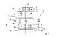
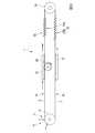
図2は、術具1の全体を示す模式図である。図3及び図4は、術具1の駆動部の構成を示す模式図である。Next, the
FIG. 2 is a schematic diagram showing the entire
本実施形態の術具1は、図1に示すスレーブアーム200a〜200dに取り付けられるものであり、マスターアーム500a、500bに入力された操作に対応して動作する。 The
図2に示すように、術具1は、体内に挿入される遠位端部2aを有する挿入部2と、挿入部2の近位端に取り付けられた駆動部10とを有する。 As shown in FIG. 2, the
挿入部2は、処置対象に対して処置をするための処置部3と、処置部3が遠位端に連結された管部8とを有する。
また、術具1は、内視鏡としての機能を有していてもよい。すなわち、術具1は内視鏡であってもよい。術具1が内視鏡である場合には、術具1は、処置部として体内を観察(処置)するための観察手段を備える。また、内視鏡として構成された場合の術具1は、観察対象あるいは処置対象に対して照明光を照射する照明手段をさらに備えていてもよい。また、術具1は、体内を観察するための手段を備えるが外科処置をするための手段を備えていなくてもよい。The insertion portion 2 includes a treatment portion 3 for performing treatment on a treatment target, and a tube portion 8 in which the treatment portion 3 is connected to a distal end.
Further, the
処置部3は、挿入部2の遠位端部に設けられている。処置部3は、処置対象に対する処置内容に対応した公知の構成を含んでよい。たとえば、処置部3の例としては、鉗子、ナイフ、マーキングデバイス、縫合器などを挙げることができる。本実施形態では、処置部3は、処置対象を把持する把持鉗子4である。 The treatment portion 3 is provided at the distal end portion of the insertion portion 2. The treatment unit 3 may include a known configuration corresponding to the treatment content for the treatment target. For example, examples of the treatment unit 3 include forceps, a knife, a marking device, and a suture instrument. In the present embodiment, the treatment unit 3 is a grasping
把持鉗子4は、公知の開閉機構により開閉動作可能であり、また、所定の回動軸5を回動の中心とした回動動作により首振りが可能である。なお、把持鉗子4に対して首振り動作させるための別の機構としては、屈曲可能に連結された複数の湾曲コマが挿入部2の遠位端に設けられ、各湾曲コマが屈曲動作することとして全体として湾曲形状に変形可能となる機構が知られている。
回動軸5の外周面には、柔軟な第一牽引部材6(第一牽引部)及び柔軟な第二牽引部材7(第二牽引部)の各々の遠位部分が巻かれている。第一牽引部材6及び第二牽引部材7の遠位端は、回動軸5に接続されている。The grasping
A distal portion of each of the flexible first traction member 6 (first traction portion) and the flexible second traction member 7 (second traction portion) is wound around the outer peripheral surface of the
なお、上記の湾曲コマが用いられた首振り機構が採用される場合には、第一牽引部材6及び第二牽引部材7の遠位端は、複数の湾曲コマのうち最も遠位端に位置する湾曲コマや、最も遠位端に位置する湾曲コマよりもさらに遠位端に近い位置にある構造物(たとえば処置部3の近位端等)に固定される。 When the swing mechanism using the curved piece is employed, the distal ends of the first pulling
第一牽引部材6及び第二牽引部材7は、回動軸5の外周面に倣って湾曲可能な柔軟性を有している。たとえば、第一牽引部材6及び第二牽引部材7は、ステンレス鋼(たとえばSUS304)を材料としてワイヤ状に形成されている。 The first pulling
本実施形態では、第一牽引部材6及び第二牽引部材7は、回動軸5の外周面に巻きつけられ且つ首振りのために牽引される。このため、第一牽引部材6及び第二牽引部材7の材質は、曲げやすく且つ伸縮しにくいことが好ましい。しかしながら、一般的に、曲げやすい材質は伸縮しやすい傾向があり、伸縮しにくい材質は曲げにくい傾向がある。本実施形態では、第一牽引部材6及び第二牽引部材7の曲げやすさと伸縮性とのバランスに着目して第一牽引部材6及び第二牽引部材7の材質が選択される。 In the present embodiment, the first pulling
管部8は、回動軸5を回動自在に保持する保持部9を遠位端に有する中空部材である。管部8の内部には、第一牽引部材6及び第二牽引部材7が進退自在に挿通されている。本実施形態では、管部8は、硬質で円筒状をなしている。なお、管部8は可撓性を有していてもよい。 The tube portion 8 is a hollow member having a holding portion 9 at the distal end for holding the
図3に示すように、駆動部10は、図1に示す処置部3を首振り動作させるための力量を発生させる動力源11と、動力源11に接続された伝達部12と、伝達部12に接続された切替部15とを有する。
動力源11は、図1に示すマスターアーム500a、500bを用いた操作入力に基づいて生成される駆動信号を受けて、マスターアーム500a、500bに対する操作入力に対応した力量を発生させる。動力源11の構成は特に限定されない。本実施形態では、たとえば、動力源11はサーボモータである。As illustrated in FIG. 3, the
The
仮に動力源11が二つあれば本実施形態のような構成にしなくとも前記課題は解決できる方法はあるが、二つ各々の動力源にクラッチ機能とそのクラッチ機構を動かすための動力源を入れなければならず、動力源が一軸につき4つの動力源が必要となり、装置の大型化に繋がる。このため、動力源11及びその補機としての別の動力源を備えることは現実的でなく、実現性が低い。また、内視鏡において体内に挿入される挿入部の遠位端部分を湾曲動作させるために内視鏡の操作部に設けられた駆動手段は手動操作によるものがよく知られているが、手動操作により動作する動力源を複数備える場合、操作入力を行うためのノブなどの構成が動力源ごとに操作部に設けられることが必要となり、また、動力源にさらに補機が必要な場合には操作入力を行うための構成がさらに増加する。すなわち、一軸に対して最低二つの操作部が必要となり、非常に操作しにくくなるので、こちらも実現性が低いと考えられる。 If there are two
伝達部12は、動力源11となるサーボモータの出力軸に固定されたウォームギア13と、ウォームギア13に噛み合うウォームホイール14とを有している。 The
ウォームギア13とウォームホイール14とは常に噛み合っており、ウォームホイール14は、ウォームホイール14の回転中心O1が後述する第一牽引ラック20と第二牽引ラック21との間の隙間を通るように、図示しない保持手段によって保持されている。また、ウォームホイール14には、後述する2本の連結軸17a,17bが進退自在に挿通される2つの貫通孔14a,14bが、各々ウォームホイール14の回転中心方向へ延ばして形成されている。 The
ウォームホイール14に形成された上記2つの貫通孔14a,14bの各々の中心は、ウォームホイール14の回転中心を間に挟んで互いに等しい距離だけ離れた位置であって、ウォームホイール14の回転中心が伸びる方向から見た時にウォームホイール14の回転中心を通る直線と平行に配置されている。なお、上記2つの貫通孔14a,14bの各々の中心は、連結軸17a,17bの位置に対応していれば、ウォームホイール14の回転中心を間に挟んで互いに等しい距離になくてもよい。 The center of each of the two through
切替部15は、ウォームホイール14の回転中心が延びる方向に進退移動可能であってウォームホイール14と一体に回転可能である移動部16と、移動部16に固定されウォームホイール14の回転中心と同軸をなすピニオン19と、第一牽引部材6に固定された第一移動体と、第二牽引部材7に固定された第二移動体とを有する。 The switching
移動部16は、ウォームホイール14の各貫通孔14a,14bに挿通されウォームホイール14の回転中心と平行に伸びる2本の連結軸17a,17bと、各連結軸17a,17bをつなぐように各連結軸17a,17bの両端に設けられた端部部材18(第一端部部材18a及び第二端部部材18b)とを有する。 The moving
2本の連結軸17a,17bは、ウォームホイール14の回転中心を間に挟んで互いに等しい距離だけ離れた位置であって、ウォームホイール14の回転中心が伸びる方向から見た時にウォームホイール14の回転中心を通る直線と平行に配置されている。
ウォームホイール14の回転中心を間に挟んで互いに等しい距離だけ離れた位置にある各貫通孔14a,14bに各連結軸17a,17bが挿入されることは、設計上及び組立上好ましい。The two connecting
It is preferable in terms of design and assembly that the connecting
なお、連結軸17a,17bが設けられていることに代えて、第一端部部材18aと第二端部部材18bとを連結する他の構造が採用されてもよい。たとえば、連結軸17a,17bに代えて、1つの連結軸により第一端部部材18aと第二端部部材18bとが連結されていてもよい。また、ウォームホイール14の回転中心に直交する断面における連結軸17a,17bの断面形状は特に限定されない。 Instead of the
第一端部部材18aと第二端部部材18bとのいずれか一方(本実施形態では第一端部部材18a)には、ピニオン19が固定されている。第一端部部材18aと第二端部部材18bの他方(本実施形態では第二端部部材18b)には、ウォームホイール14の回転中心方向に移動部16を移動させるためのアクチュエータが連結されている。 The
第二端部部材18b及びこれに連結されるアクチュエータの構成は、第二端部部材18bがウォームホイール14の回転中心を中心として回転可能であってかつ第二端部部材18bがウォームホイール14の回転中心方向に進退移動可能であれば、特に限定されることはない。 The configuration of the
図5は、第二端部部材18bがウォームホイール14の回転中心を中心として回転可能であってかつ第二端部部材18bがウォームホイール14の回転中心方向に進退移動可能となる構成の一例を示した模式的な側面図である。また、図6は、図5の下面図である。 FIG. 5 shows an example of a configuration in which the
図5に示すように、第二端部部材18bとアクチュエータ25との構成の一例としては、図5に示すように、第二端部部材18bが、ウォームホイール14の回転中心を中心とする円形の溝部18cを外周面に有する円板状であり、アクチュエータ25が、第二端部部材18bの溝部18cに一部が挿入されるU字状部材26と、U字状部材26をウォームホイール14の回転中心方向に進退移動させるモータ27とを有する。 As shown in FIG. 5, as an example of the configuration of the
図5及び図6に示すように、U字状部材26は、溝部18cにおける溝の底部分(溝部18cの内部においてウォームホイール14の回転中心を中心とする円柱面をなす部分)の外面に倣った形状を有しており、U字状部材26がモータ27によってウォームホイール14の回転中心方向に進退移動されると、U字状部材26が溝部18cに引っかかって第二端部部材18bをウォームホイール14の回転中心方向へと直線移動させる。また、このとき、U字状部材26は、ウォームホイール14の回転中心を中心とした第二端部部材18bの回転移動を規制しない。 As shown in FIGS. 5 and 6, the
また、アクチュエータ25は、U字状部材26がウォームホイール14の回転中心方向に移動することを許容しウォームホイール14の回転中心方向に対して交差する方向にずれるのを規制するガイドをさらに備えていてもよい。 The
なお、第一端部部材18aに上記溝部18cと同様の溝部が形成され、U字状部材26に代えて、またはU字状部材26に加えて、第一端部部材18aの溝部に挿入されるU字状部材が設けられていてもよい。この場合、第一端部部材18aの溝部に挿入されるU字状部材は、モータ27によって動作されてよい。 In addition, the groove part similar to the said
また、第二端部部材18bとアクチュエータとの構成の他の一例は、第二端部部材18bの外周面に、ウォームホイール14の回転中心を中心とした螺旋形状をなす複数の傾斜凸部が形成され、駆動部10の筐体(不図示)に、傾斜凸部が係合するように凹凸形状を有する孔が形成された支持孔部を有する構成である(たとえば図16参照)。
また、第二端部部材18bとアクチュエータとの構成のさらに一例としては、第二端部部材18bが、ウォームホイール14の回転中心方向に厚さを有する円板状をなし、アクチュエータが、第二端部部材18bの厚さ方向の両端面に対して摺動可能に係合する連結部と、ウォームホイール14の回転中心方向に連結部を進退移動させるモータを有している。Another example of the configuration of the
Further, as a further example of the configuration of the
ピニオン19は、移動部16の第一端部部材18aに固定されている。また、本実施形態は、ピニオン19は、平歯車である。なお、ピニオン19に形成された歯には、後述する第一移動体(第一牽引ラック20)及び第二移動体(第二牽引ラック21)に対する連結をスムーズにするためのテーパが形成されていてもよい。また、ピニオン19とウォームホイール14とは同一の回転中心O1を中心に回転するようになっている。 The
本実施形態における第一移動体は、第一牽引部材6が固定された第一牽引ラック20(第一ラック部)である。第一牽引ラック20は、ピニオン19の歯と噛み合う歯がその長手方向に並べられた棒状部材であり、第一牽引ラック20の遠位端に第一牽引部材6の近位端が固定されている。 The first moving body in the present embodiment is a first traction rack 20 (first rack portion) to which the
本実施形態における第二移動体は、第二牽引部材7が固定された第二牽引ラック21(第二ラック部)である。第二牽引ラック21は、ピニオン19の歯と噛み合う歯がその長手方向に並べられた棒状部材であり、第二牽引ラック21の遠位端には第二牽引部材7の近位端が固定されている。 The 2nd mobile body in this embodiment is the 2nd pulling rack 21 (2nd rack part) to which the 2nd pulling
第一牽引ラック20と第二牽引ラック21とは、互いに平行に延びている。第一牽引ラック20と第二牽引ラック21との各々の歯は、互いに向き合った状態とされている。第一牽引ラック20の歯と第二牽引ラック21の歯とには、いずれも、ピニオン19の歯が好適に噛み合う。本実施形態では、ピニオン19の回転中心O1方向において第一牽引ラック20と第二牽引ラック21とは互いにずれた位置にあり、かつ、ピニオン19の回転中心O1方向及び第一牽引ラック20の長手方向に対して直交する方向O2において、第二牽引ラック21は第一牽引ラック20から離間している。ピニオン19の回転中心O1方向及び第一牽引ラック20の長手方向に対して直交する方向O2における第一牽引ラック20と第二牽引ラック21との距離は、ピニオン19の直径とほぼ等しい。 The
ピニオン19は、第一牽引ラック20と第二牽引ラック21との各々に対して、排他的に連結される。すなわち、ピニオン19は、その回転中心O1方向において、ピニオン19と第一牽引ラック20とが噛み合う位置と、ピニオン19と第二牽引ラック21とが噛み合う位置との間で、移動部16により直線方向に進退移動されることが可能である。 The
図3に示すようにピニオン19と第一牽引ラック20とが噛み合った状態は、ピニオン19から第一牽引ラック20へと動力の伝達が可能な状態(第一伝達状態)であり、図4に示すようにピニオン19と第二牽引ラック21とが噛み合った状態は、ピニオン19から第二牽引ラック21へと動力の伝達が可能な状態(第二伝達状態)である。 As shown in FIG. 3, the state where the
なお、第一牽引ラック20と第二牽引ラック21にピニオン19がともに噛み合った状態(第三伝達状態)があってもよい。第一牽引ラック20と第二牽引ラック21にピニオン19がともに噛み合った状態では、たとえばピニオン19がラック20から第二牽引ラック21へと移動する際に、第一牽引ラック20に対する噛み合いを残しながら第二牽引ラック21にも噛み合うこととなり、また、ピニオン19が第二牽引ラック21から第一牽引ラック20へと移動する際に、第二牽引ラック21に対する噛み合いを残しながら第一牽引ラック20にも噛み合うこととなる。このため、上記第三伝達状態を介して第一伝達状態と第二伝達状態との切り替えが行われると、第一伝達状態と第二伝達状態とが急激に切り替わって意図しない力量が処置部3に伝わることが予防される。 Note that there may be a state (third transmission state) in which the
このため、本実施形態の切替部15は、動力源11から第一牽引部材6へ力量を伝達する第一経路と、動力源11から第二牽引部材7へ力量を伝達する第二経路とを有し、ピニオン19をその回転中心O1方向へと移動させることによって、第一経路と第二経路とを排他的に切り替える。すなわち、切替部15は、上記第一伝達状態と上記第二伝達状態とが互いに切り替わるようにピニオン19を移動部16が移動させることにより、動力源11が発生させる力量を第一牽引部材6または第二牽引部材7に排他的に切り替えて伝達する。 For this reason, the switching
次に、本実施形態の術具1の作用について説明する。図7及び図8は術具1の作用を説明するための図である。
本実施形態の術具1は、スレーブアームに固定され、駆動部10の動力源11が、マスターアームに対する操作入力に従って動作する。術具1において第一牽引部材6を牽引する場合には、移動部16のウォームホイール14を回転させる動力源11が動作する前に、移動部16の第二端部部材18bを移動させるアクチュエータ(たとえば図5に示すアクチュエータ25等)が動作する。すなわち、まず、第二端部部材18bを移動させる図示しないアクチュエータが、第一牽引ラック20の歯にピニオン19の歯が噛み合う位置まで、ピニオン19をその回転中心方向に沿って移動させる(図3参照)。その後、移動部16のウォームホイール14を回転させる動力源11が動作することにより、ピニオン19から第一牽引ラック20へは動力が伝達されるがピニオン19から第二牽引ラック21へは動力が伝達されない状態(上記第一伝達状態)となる。
また、上記第三伝達状態を介する場合には、ウォームホイール14の回転中心方向へのピニオン19の移動は、ピニオン19の回転動作中に生じる。Next, the operation of the
The
Further, in the case of passing through the third transmission state, the movement of the
なお、本実施形態において、第一牽引部材6は柔軟なワイヤ状であるので、第一牽引部材6を用いた処置部3への力量の伝達のためには、第一牽引部材6を牽引する力が利用される。これは、第一牽引部材6をその長手方向に押圧する力は、第一牽引部材6が撓むように第一牽引部材6を変形させたり第一牽引部材6を意図しない位置に移動させてしまう可能性が考えられるからである。本実施形態においては、第一牽引部材6を処置部3側へ向けて押圧する力は、処置部3を動作させるための力量の伝達としては積極的には利用されていない。 In the present embodiment, since the
図7及び図8は、第一牽引ラック20と第二牽引ラック21とのどちらにピニオン19が噛み合っているかがわかりやすくなるように表現された模式図であり、ピニオン19の回転中心O1方向から実際に第一牽引ラック20及び第二牽引ラック21を見た場合の見え方とは異なる。すなわち、第一牽引ラック20と第二牽引ラック21との一方のみにピニオン19が噛み合っている場合、実際は、ピニオン19の回転中心O1方向から見た場合にピニオン19が第一牽引ラック20及び第二牽引ラック21の両方に接しているように見えるが、図7及び図8においては、第一牽引ラック20と第二牽引ラック21とのうちピニオン19と噛み合っていない方はピニオン19が離間したように図示されている。 7 and 8 are schematic views that are expressed so that it is easy to understand which of the
ここで、図7に示すように、ピニオン19と第一牽引ラック20とが噛み合った状態において、ピニオン19と第二牽引ラック21とが噛み合っていたとすると、第一牽引ラック20が第一牽引部材6を牽引する動作と同時に、第二牽引ラック21が第二牽引部材7を押圧する動作が生じる。本実施形態では、ピニオン19と第一牽引ラック20とが噛み合った状態では、第二牽引ラック21はピニオン19から離れており、第二牽引ラック21は第二牽引部材7を押圧しない。このため、第一牽引部材6の牽引時に第二牽引部材7が撓んだり意図せず移動したりすることが予防されている。 Here, as shown in FIG. 7, assuming that the
また、処置部3に第一牽引部材6から力量が伝達された場合に、第一牽引部材6の牽引力が処置部3を介して第二牽引部材7へと伝わる可能性もある。本実施形態では、第一牽引部材6の牽引時には第二牽引ラック21とピニオン19とが離間しているので、第一牽引部材6の牽引力が処置部3を介して第二牽引部材7に伝わった場合には、第二牽引部材7は、ピニオン19による規制を受けることなく第二牽引ラック21の長手方向に沿って第二牽引ラック21を移動させることにより弛みにくくなっている。 In addition, when a force is transmitted from the
逆に、術具1において第二牽引部材7を牽引する場合には、移動部16のウォームホイール14を回転させる動力源11が動作する前に、移動部16の第二端部部材18bを移動させるためのアクチュエータ(図5に示すアクチュエータ25等)が動作する。すなわち、まず、第二端部部材18bを移動させる上記アクチュエータが、第二牽引ラック21の歯にピニオン19の歯が噛み合う位置まで、ピニオン19をその回転中心O1方向に沿って移動させる(図4参照)。その後、移動部16のウォームホイール14を回転させる動力源11が動作することにより、ピニオン19から第二牽引ラック21へは動力が伝達されるがピニオン19から第一牽引ラック20へは動力が伝達されない状態(上記第二伝達状態)となる。 Conversely, when the
また、動力源11の動作と上記アクチュエータの動作とが同時であってもよい、この場合、ピニオン19が第一牽引ラック20と第二牽引ラック21との両方に噛み合い、ピニオン19の回転は第一牽引ラック20及び第二牽引ラック21の両方に一時的に伝達される状態(上記第三伝達状態)となる。 Further, the operation of the
なお、本実施形態において、第二牽引部材7は第一牽引部材6と同様に柔軟なワイヤ状であるので、第二牽引部材7を用いた処置部3への力量の伝達は、第二牽引部材7を牽引する力を利用する。本実施形態においては、第二牽引部材7を処置部3側へ向けて押圧する力は、第一牽引部材6と同様に、処置部3を動作させるための力量の伝達としては積極的には利用されていない。 In the present embodiment, since the
ここで、ピニオン19と第二牽引ラック21とが噛み合った状態において、ピニオン19と第一牽引ラック20とが噛み合っていたとすると、第二牽引ラック21が第二牽引部材7を牽引する動作と同時に、第一牽引ラック20が第一牽引部材6を押圧する動作が生じる。本実施形態では、ピニオン19と第二牽引ラック21とが噛み合った状態では、第一牽引ラック20はピニオン19から離れており、第一牽引ラック20は第一牽引部材6を押圧しない。このため、第二牽引部材7の牽引時に第一牽引部材6が撓んだり意図せず移動したりすることが予防されている。 Here, if the
また、処置部3に第二牽引部材7から力量が伝達された場合に、第二牽引部材7の牽引力が処置部3を介して第一牽引部材6へと伝わる可能性もある。本実施形態では、第二牽引部材7の牽引時には第一牽引ラック20とピニオン19とが離間しているので、第二牽引部材7の牽引力が処置部3を介して第一牽引部材6に伝わった場合には、第一牽引部材6は、ピニオン19による規制を受けることなく第一牽引ラック20の長手方向に沿って第一牽引ラック20を移動させることにより弛みにくくなっている。 In addition, when a force is transmitted from the
このように、本実施形態では、第一牽引部材6と第二牽引部材7とは、牽引されている側は駆動部10からの駆動力が確実に伝わり、牽引を必要としない側は、駆動部10からの駆動力の影響を直接は受けない。また、たとえば第一牽引部材6が牽引される場合、駆動部10から処置部3までの間に駆動力を吸収するばねなどが存在しないので、動力源11が発生させる力量のロスが少ない。また、第二牽引部材7が牽引される場合も同様に力量のロスが少ない。 Thus, in the present embodiment, the
また、切替部15において動力の伝達経路を排他的に切り替えるので、第一牽引ラック20を牽引するための動力と第二牽引ラック21を牽引するための動力とを別に備える必要がなく、装置構成をコンパクトにすることができる。 In addition, since the power transmission path is exclusively switched in the
(変形例1)
次に、上記実施形態の変形例について説明する。図9は、本実施形態の術具の変形例の構成を示す模式図である。
図9に示すように、本変形例では、上記実施形態で説明した切替部15は、第一牽引部材6のうち第一牽引部材6と第一牽引ラック20との接触位置から処置部3に至るまでの第一領域A1と、第二牽引部材7のうち第二牽引部材7と第二牽引ラック21との接触位置から処置部3に至るまでの第二領域A2との各々に張力を付与する張力付与部22をさらに備えている。(Modification 1)
Next, a modification of the above embodiment will be described. FIG. 9 is a schematic diagram showing a configuration of a modified example of the surgical instrument of the present embodiment.
As shown in FIG. 9, in the present modification, the switching
張力付与部22は、第一牽引部材6及び第二牽引部材7の各々を独立して近位端側へ移動させる付勢力を付与する付勢部材23(第一付勢部材23a及び第二付勢部材23b)を有している。 The
第一付勢部材23aは、第一牽引ラック20の近位端に固定され、第一牽引ラック20を近位側へ牽引する引張ばねである。 The
第二付勢部材23bは、第二牽引ラック21の近位端に固定され、第二牽引ラック21を近位側へ牽引する引張ばねである。 The
第一付勢部材23a及び第二付勢部材23bの各々の付勢力は、ピニオン19によって第一牽引ラック20及び第二牽引ラック21を移動させることができる程度であり、且つ第一牽引ラック20あるいは第二牽引ラック21からピニオン19が離れることにより動力伝達経路が切断された状態では第一牽引部材6及び第二牽引部材7を弛みのない状態まで牽引することが出来る程度の大きさに設定される。 The urging force of each of the first urging
本変形例では、第一牽引部材6或いは第二牽引部材7を処置部3側へ押圧しないことに加えて、第一牽引部材6と第二牽引部材7とのうち処置部3を動作させるための力量を伝達するために使用されている側と反対側は第一付勢部材23aまたは第二付勢部材23bによって弛みが除去される。 In this modification, in addition to not pressing the
また、第一付勢部材23aと第二付勢部材23bとは、プーリ24を介して互いに連結されている。これにより、第一付勢部材23aにかかる力量は第二付勢部材23bへと伝わり、第二付勢部材23bにかかる力量は第一付勢部材23aに伝わる。
たとえば、第一付勢部材23aと第二付勢部材23bとの各々の基端が固定端であると、処置部3を大きく動作させると処置部3の動作量に伴って第一付勢部材23aあるいは第二付勢部材23bにかかる荷重が増加する。このときに第一付勢部材23aあるいは第二付勢部材23bにかかる荷重が抵抗となって、処置部3に対して大きな力をかけにくくなることが考えられる。つまり、第一牽引部材6あるいは第二牽引部材7に対する張力が一定でなくなる。The first urging
For example, if the base ends of the first urging
これに対して、本変形例では、第一付勢部材23aと第二付勢部材23bとがプーリ24を介して連結されているので、処置部3を大きく動作させたときに、プーリ24が回転することにより、第一付勢部材23aあるいは第二付勢部材23bに過大な荷重がかかるのを防ぐことができる。このため、処置部3を大きく動作させた場合でも、第一付勢部材23aや第二付勢部材23bにかかる荷重を適正化し、処置部3を動作させるための力量を発生させやすくなる。つまり、第一付勢部材23aと第二付勢部材23bとの各々の基端が固定端である場合と異なり、本変形例では、第一牽引部材6あるいは第二牽引部材7に対する張力が一定となるので、処置部3の動作性が向上する。また、本変形例によれば、処置部3の角度がどのようになっても、上記したように一定の張力になるので、この点においても、処置部3の動作性が向上する。 On the other hand, in this modification, since the first urging
(変形例2)
次に、本実施形態の他の変形例について、図10を参照して説明する。
図10は、本変形例の構成を示す模式図である。
図10に示すように、本変形例では、第一付勢部材23a及び第二付勢部材23bを備えることに代えて、プーリ24を近位側へと押圧するための付勢部材23Aが設けられている。本変形例では、付勢部材23Aは、プーリ24を近位側へ押圧可能な圧縮バネである。(Modification 2)
Next, another modification of the present embodiment will be described with reference to FIG.
FIG. 10 is a schematic diagram showing the configuration of this modification.
As shown in FIG. 10, in this modification, instead of providing the
このような構成であっても、第一牽引ラック20側と第二牽引ラック21側との間で荷重の移動がプーリ24を介して生じ、また、第一牽引部材6あるいは第二牽引部材7の弛みを除去するための牽引力が付勢部材23Aによってかけられる。
また、上記変形例1と比較してバネ要素が少ないので、簡易な構成とすることができる。Even in such a configuration, the movement of the load occurs between the
Moreover, since there are few spring elements compared with the said
(第2実施形態)
次に、本発明の第2実施形態について説明する。図11は、本実施形態の術具を示す模式図である。図12は、本実施形態の術具の作用を説明するための図である。
図11及び図12に示すように、本実施形態の術具1Aは、挿入部2と駆動部10とを切り離すことができる。挿入部2は、体内に挿入される遠位端部2aを有しているので、頻繁に滅菌される。また、例えば高圧蒸気滅菌やエチレンオキサイドガスなどを用いた滅菌など様々な滅菌に対応させる必要があり、電子機器や回路などは挿入部2に配されていないほうが好ましい。これに対して、駆動部10は、体内に挿入される部分を有しておらず、滅菌済みのドレープによって覆うことで十分である。(Second Embodiment)
Next, a second embodiment of the present invention will be described. FIG. 11 is a schematic diagram showing the surgical instrument of the present embodiment. FIG. 12 is a diagram for explaining the operation of the surgical instrument of the present embodiment.
As shown in FIGS. 11 and 12, the
本実施形態の術具1Aは、第1実施形態で説明した切替部15に代えて、構成が異なる切替部15Aを有する。 The
切替部15Aは、第1実施形態で説明した第一ラック部及び第二ラック部と構成が異なる第一ラック部30A及び第二ラック部35Aを有する。 The
第一ラック部30Aは、第一牽引部材6が固定された第一牽引ラック20と、第一牽引ラック20の歯と向い合わせられた歯を有し第一牽引ラック20と平行に配された第一対向ラック31と、第一牽引ラック20と第一対向ラック31とをつなぐように第一牽引ラック20と第一対向ラック31との両方に噛み合わされた第一ギア32と、第1実施形態で説明したピニオン19に噛合可能で第一対向ラック31の長手方向にピニオン19によって進退動作可能な第一押圧ラック33とを有する。 The first rack portion 30 </ b> A has a
第一押圧ラック33は、第一対向ラック31の近位端に第一押圧ラック33の遠位端が第一付勢部材23cの付勢力により当接するようになっている。第一押圧ラック33は、第一対向ラック31に固定される必要はない。すなわち、本実施形態では、挿入部2と駆動部10との切り離しは、第一押圧ラック33と第一対向ラック31とが分離可能であることにより達成される。 The first
第一ギア32は、第一牽引ラック20と第一対向ラック31とを常に繋いており、第一牽引ラック20の移動方向は、第一ギア32によって、第一対向ラック31の移動方向とは反対方向となっている。 The
第二ラック部35Aは、第二牽引部材7が固定された第二牽引ラック21と、第二牽引ラック21の歯と向い合わせられた歯を有し第二牽引ラック21と平行に配された第二対向ラック36と、第二牽引ラック21と第二対向ラック36とをつなぐように第二牽引ラック21と第二対向ラック36との両方に噛み合わされた第二ギア37と、第1実施形態で説明したピニオン19に噛合可能で第二対向ラック36の長手方向にピニオン19によって進退動作可能な第二押圧ラック38とを有する。 The second rack portion 35 </ b> A has a second pulling
第二押圧ラック38は、第二対向ラック36の近位端に第二押圧ラック38の遠位端が第二付勢部材23dの付勢力により当接するようになっている。第二押圧ラック38は、第二対向ラック36に固定される必要はない。すなわち、本実施形態では、挿入部2と駆動部10との切り離しは、第二押圧ラック38と第二対向ラック36とが分離可能であることにより達成される。 The second
第二ギア37は、第二牽引ラック21と第二対向ラック36とを常に繋いており、第二牽引ラック21の移動方向は、第二ギア37によって、第二対向ラック36の移動方向とは反対方向となっている。 The
また、本実施形態の術具1Aには、第1実施形態で説明した張力付与部22に代えて、第一対向ラック31及び第二対向ラック36に接続された張力付与部22Aが設けられている。張力付与部22Aは、第一対向ラック31の遠位端に接続された第一付勢部材23aと、第二対向ラック36の遠位端に接続された第二付勢部材23bとを有する。第一付勢部材23aと第二付勢部材23bとの各々の遠位端は、プーリ41によって折り返されて配された連結ワイヤ39によって連結されている。 Further, the
本実施形態における張力付与部22Aは、第一付勢部材23aが第一対向ラック31を近位側へ牽引することによって第一牽引ラック20を遠位側へと移動させ、第二付勢部材23bが第二対向ラック36を近位側へ牽引することによって第二牽引ラック21を遠位側へ移動させることにより、第1実施形態と同様の作用を有する。 In the
次に、本実施形態の術具1Aの作用について説明する。
図11に示すように、本実施形態の術具1Aは、第一押圧ラック33が第一対向ラック31の近位端を押圧すると、第一押圧ラック33が第一対向ラック31を遠位側へと移動させる。さらに、第一対向ラック31は第一ギア32を回転させ、第一牽引部材6に固定された第一牽引ラック20を第一ギア32が近位側へと移動させる。これにより、本実施形態の術具1Aにおいて第一押圧ラック33が遠位側へ移動されると、第一牽引部材6は近位側へと牽引される。Next, the operation of the
As shown in FIG. 11, in the
なお、第一押圧ラック33が遠位側へと移動する過程において、第二押圧ラック38からはピニオン19が離間しているので、第二押圧ラック38を移動させる力はピニオン19からは伝わらない。このため、第二牽引部材7を遠位側へと移動させる力はかからない。さらに、張力付与部22Aの第二付勢部材23bが第二牽引部材7に対して張力を付与し続けているので、第二牽引部材7の弛みが除去される。 In the process of moving the first
また、図12に示すように、第二押圧ラック38が第二対向ラック36の近位端を押圧すると、第二押圧ラック38が第二対向ラック36を遠位側へと移動させる。さらに、第二対向ラック36は第二ギア37を回転させ、第二牽引部材7に固定された第二牽引ラック21を第二ギア37が近位側へと移動させる。これにより、本実施形態の術具1Aにおいて第二押圧ラック38が遠位側へ移動されると、第二牽引部材7は近位側へと牽引される。 Also, as shown in FIG. 12, when the second
なお、第二押圧ラック38が遠位側へと移動する過程において、第一押圧ラック33からはピニオン19が離間しているので、第一押圧ラック33を移動させる力はピニオン19からは伝わらない。このため、第一牽引部材6を遠位側へと移動させる力はかからない。さらに、張力付与部22Aの第一付勢部材23aが第一牽引部材6に対して張力を付与し続けているので、第一牽引部材6の弛みが除去される。 In the process of moving the second
(変形例)
次に、本実施形態の変形例について説明する。図13は本実施形態の術具の変形例の構成を示す模式図である。
本変形例では、図11に示す張力付与部22Aが第一付勢部材23a及び第二付勢部材23bを備えることに代えて、図13に示すように、第一対向ラック31と第二対向ラック36とを連結する連結ワイヤ39aと、連結ワイヤ39aに対して張力を付与するばね部40とを有する。(Modification)
Next, a modification of this embodiment will be described. FIG. 13 is a schematic diagram showing a configuration of a modified example of the surgical instrument of the present embodiment.
In this modification, instead of the
ばね部40は、連結ワイヤ39が外周面にかけられたプーリ41aと、プーリ41aを遠位端側へ押圧する圧縮ばね42とを有する。 The
本変形例では、上記第2実施形態で説明した構成では第一付勢部材23aと第二付勢部材23bとの2つの付勢要素を備えていたことに変えて、ばね部40という1つの付勢要素によって上記第2実施形態に記載されたように第一付勢部材23aと第二付勢部材23bを用いた場合と同様の効果が得られる。 In this modification, in the configuration described in the second embodiment, the two urging elements of the first urging
(変形例)
次に、本実施形態の他の変形例について説明する。
図13に示すように、本変形例では、第一押圧ラック33及び第二押圧ラック38を連結する連結ワイヤ39bと、連結ワイヤ39bを遠位側へ押圧するばね部40bを備える。すなわち、本変形例では、ばね部40bは、第一押圧ラック33及び第二押圧ラック38を遠位側へ移動させるように作用する。ばね部40bは、上記第2実施形態のばね部40と同様に、プーリ41bと圧縮ばね42bとを有する。(Modification)
Next, another modification of the present embodiment will be described.
As shown in FIG. 13, the present modification includes a connecting
術具1Aの挿入部2と駆動部10とが切り離されているときには、第一押圧ラック33は第一対向ラック31から離間しており、第二押圧ラック38は第二対向ラック36から離間しているので、ばね部40bが第一押圧ラック33及び第二押圧ラック38に伝える付勢力によって、第一押圧ラック33及び第二押圧ラック38はいずれも遠位側に移動された位置にある。 When the insertion part 2 and the
術具1Aの挿入部2と駆動部10とが取り付けられているときには、ばね部40bは、第一押圧ラック33を第一対向ラック31の近位端に押し付け、第二押圧ラック38を第二対向ラック36の近位端に押し付ける。 When the insertion part 2 and the
さらに、術具1Aにおいてピニオン19が回転される動作においては、第一対向ラック31と第二対向ラック36とのうちピニオン19が噛み合っていない側をばね部40の圧縮ばね42によって遠位端側へと移動させる力が伝わり、上記第2実施形態で説明した張力付与部22Aと同様に第一牽引部材6と第二牽引部材7とのうち処置部3の牽引動作に寄与していない側に対して弛みを除去する。 Further, in the operation in which the
(第3実施形態)
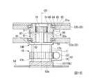
次に、本発明の第3実施形態について説明する。図14は、本実施形態の術具を示す模式図である。図15及び図16は、同術具における駆動部を示す模式図である。
図14、図15及び図16に示すように、本実施形態の術具1Bは、第1実施形態で説明した切替部15に代えて、第1実施形態の切替部15とは構成が異なる切替部15Bを有する。また、本実施形態においては、第一牽引部材6と第二牽引部材7とは、一続きの線状部材によって構成されている。(Third embodiment)
Next, a third embodiment of the present invention will be described. FIG. 14 is a schematic diagram showing the surgical instrument of the present embodiment. FIG.15 and FIG.16 is a schematic diagram which shows the drive part in the same surgical instrument.
As shown in FIGS. 14, 15, and 16, the
切替部15Bは、第1実施形態で説明した第一牽引ラック20に代えて、第一牽引部材6が摩擦係合する外周面50aを有する第一内歯車50が第一移動体として設けられており、第1実施形態で説明した第二牽引ラック21に代えて、第二牽引部材7が摩擦係合する外周面51aを有する第二内歯車51が第二移動体として設けられている。 Instead of the
また、第一牽引部材6と第二牽引部材7とは、第1実施形態の変形例にて説明された張力付与部22と同様の効果を得るための張力付与部22Bを介して連結されている。
張力付与部22Bは、第一牽引部材6及び第二牽引部材7となる線状部材が外周面に巻かれたプーリ55と、プーリ55を回転自在に保持するプーリ保持部56と、駆動部10における遠位端と近位端とを結ぶ方向にプーリ保持部56をスライド可能に保持するガイド57と、プーリ保持部56の遠位側に配されプーリ保持部56を近位側へ向かって押圧するためのバネ58と、バネ58の遠位端を支持する支持部59とを備える。Moreover, the
The
バネ58は、第一牽引部材6及び第二牽引部材7を構成する線状部材に対して一定の張力がかかるように、プーリ保持部56をガイド57に沿って移動させ、第一牽引部材6及び第二牽引部材7を構成する線状部材に対して一定の張力がかかっている位置でプーリ保持部56を保持する。 The
なお、本実施形態の張力付与部22Bは、第一牽引部材6が第一内歯車50の外周面50aにかけられていることにより、第一牽引部材6において処置部3に対する連結端と反対側の端を、術具1Bにおける近位端側ではなく、術具1Bにおける遠位端側に牽引している点が上記第1実施形態と異なっている。同様に、本実施形態の張力付与部22Bは、第二牽引部材7が第二内歯車51の外周面51aにかけられていることにより、第二牽引部材7において処置部3に対する連結端と反対側の端を、術具1Bにおける近位端側ではなく、術具1における遠位端側に牽引している点が上記第1実施形態と異なっている。 In addition, the tension |
図15及び図16に示すように、第一内歯車50と第二内歯車51は、同一の回転中心O3を中心として互いに独立して回転自在であり、各々、ピニオン19と噛み合い可能である。具体的には、切替部15Bは、第一内歯車50と第二内歯車51とが共に内部に収容されるギアケース52を有している。
ギアケース52は、軸受け62を介して第一内歯車50に連結された第一支持部61と、軸受け64を介して第二内歯車51に連結された第二支持部63と、軸受け64を保持するための第一保持部材65及び第二保持部材66とを有する。
第一支持部61と第二支持部63とは、第一内歯車50及び第二内歯車51がともに第一支持部61と第二支持部63との間に収容されるように、ワッシャ67により隙間が空いた状態で互いの位置関係が固定状態にある。ギアケース52は、第一内歯車50と第二内歯車51とが同一の回転中心を中心として互いに独立して回転可能となるように第一内歯車50と第二内歯車51とを保持する保持部を成している。
本実施形態では、軸受け62及び軸受け64はボールベアリングからなる。
軸受け62における外周側の環は第一支持部61に嵌合されている。軸受け62における内周側の環は第一内歯車50にねじの噛み合いにより嵌合されている。
軸受け64における外周側の環は第二支持部63に嵌合されるとともに第一保持部材65によって覆われる。第一保持部材65は、第二支持部63にたとえば接着等によって固定される。軸受け64における内周側の環は第二内歯車51に嵌合されるとともに、第二保持部材66によって覆われる。
第二保持部材66は、第二内歯車51にねじの噛み合いにより嵌合される。
第一内歯車50及び第二内歯車51は、ボールベアリング(軸受け62,64)を介してギアケース52に保持されている。このため、第一内歯車50及び第二内歯車51が回転操作する際の摺動抵抗は小さい。また、本実施形態では、軸受け62,64が嵌合されワッシャ67が介装された状態の第一内歯車50及び第二内歯車51をギアケース52内に収容した後に第一保持部材65によって蓋をすることで、第一内歯車50及び第二内歯車51を容易にギアケース52内に組み込むことができる。As shown in FIGS. 15 and 16, the first
The
The
In this embodiment, the
The ring on the outer peripheral side of the
The ring on the outer peripheral side of the
The second holding
The first
本実施形態では、第一内歯車50がピニオン19と噛み合っている状態では、第二内歯車51はピニオン19から離間した状態となっており、第二内歯車51がピニオン19と噛み合っている状態では、第一内歯車50はピニオン19から離間した状態となっている。これにより、本実施形態においても、ピニオン19の移動によって、図15に示すように動力源11から第一牽引部材6へと動力が伝達される状態(第一伝達状態)と、図16に示すように動力源11から第二牽引部材7へと動力が伝達される状態(第二伝達状態)とが、排他的に選択される。 In the present embodiment, when the first
また、切替部15Bは、移動部16の第二端部部材18bを移動させる機構として、第1実施形態で説明した円板(第二端部部材18b)、連結部及びアクチュエータ(いずれも不図示)に代えて、カム板53と支持孔部54とを有する。 In addition, the
カム板53は、ウォームホイール14の回転中心O3を中心として回転可能な円板状をなしており、カム板53の外周面には、カム板53の回転中心を中心とした螺旋形状をなす複数の傾斜凸部53aが形成されている。 The
支持孔部54は、カム板53の傾斜凸部53aが係合するように凹凸形状を有する孔であり、本実施形態では、駆動部10の筐体(不図示)に固定されている。
本実施形態では、カム板53の傾斜凸部53aは多条ねじであり、支持孔部54は傾斜凸部53aに噛み合う多条ナットである。The
In the present embodiment, the inclined
カム板53が支持孔部54に係合した状態でカム板53がその回転中心(カム板53の回転中心は第一内歯車50及び第二内歯車51の回転中心O3と同軸である。)を中心として回転すると、支持孔部54とカム板53とが係合していることにより、カム板53の回転力によって、カム板53がその回転中心O3方向に回転しながらその回転中心O3方向に沿って進退移動する。 With the
カム板53の回転方向とカム板53の進退移動方向との関係は、第一内歯車50が第一牽引部材6を牽引する方向に回転するようにピニオン19が回転するピニオン19の回転時に、カム板53がピニオン19を第一内歯車50へ向かって押すようになっており、第二内歯車51が第二牽引部材7を牽引する方向に回転するようにピニオン19が回転するピニオン19の回転時に、カム板53がピニオン19を第二内歯車51へ向かって押すようになっている。
なお、本実施形態においても、上記第1実施形態と同様に、アクチュエータ(たとえば図5に示すアクチュエータ25)を用いてウォームホイール14を移動させる構成が採用されていてもよい。The relationship between the rotation direction of the
In the present embodiment, as in the first embodiment, a configuration in which the
本実施形態の術具1Bの作用について説明する。
本実施形態では、ピニオン19と第一内歯車50との噛み合いと、ピニオン19と第二内歯車51との噛み合いとが、カム板53及び支持孔部54によるピニオン19の進退動作によって、ウォームホイール14を回転させるサーボモータの動力の一部を用いて切り替えられる。このため、第一牽引部材6を牽引するためにウォームホイール14を回転させるときには第一牽引部材6のみに動力が伝達され、第二牽引部材7を牽引するためにウォームホイール14を回転させるときには第二牽引部材7のみに動力が伝達される。The operation of the
In the present embodiment, the meshing of the
また、本実施形態においても上記第1実施形態の変形例と同様に、第一牽引部材6と第二牽引部材7とのうち処置部3の牽引のための力量がかかるのと反対側は、張力付与部22Bによって弛みが除去される。 Also in the present embodiment, as in the modification of the first embodiment, the opposite side of the
以上、本発明の好ましい実施例を説明したが、本発明はこれら実施例に限定されることはない。本発明の趣旨を逸脱しない範囲で、構成の付加、省略、置換、およびその他の変更が可能である。
例えば、上記実施形態では、切替部としてピニオン19の移動をその回転中心軸線上に移動する構成としているが、図7,8,11,12に示す様なピニオン19の回転中心軸が水平移動する構成としても良い。
また、上記第2実施形態において、第一牽引ラック20と第一対向ラック31とは必ずしも平行である必要はなく、第二牽引ラック21と第二対向ラック36とは必ずしも平行である必要はない。
また、上記第3実施形態において、第一牽引部材6と第二牽引部材7とが別体であってもよい。この場合には、第一牽引部材6の遠位端部が第一内歯車50の外周面に巻かれ、第二牽引部材7の遠位端部が第二内歯車51の外周面に巻かれて接続される構成であってもよい。
また、上述の各実施形態及び各変形例において示した構成要素は適宜に組み合わせて構成することが可能である。The preferred embodiments of the present invention have been described above, but the present invention is not limited to these embodiments. Additions, omissions, substitutions, and other modifications can be made without departing from the spirit of the present invention.
For example, in the embodiment described above, the movement of the
Moreover, in the said 2nd Embodiment, the
In the third embodiment, the
In addition, the constituent elements shown in the above-described embodiments and modifications can be combined as appropriate.
1,1A,1B 術具
2 挿入部
2a 遠位端部
3 処置部
4 把持鉗子
5 回動軸
6 第一牽引部材(第一牽引部)
7 第二牽引部材(第二牽引部)
8 管部
9 保持部
10 駆動部
11 動力源
12 伝達部
13 ウォームギア
14 ウォームホイール
15,15A,15B 切替部
16 移動部
17a,17b 連結軸
18 端部部材
19 ピニオン
20 第一牽引ラック(第一移動体、第一ラック部)
21 第二牽引ラック(第二移動体、第二ラック部)
22,22A,22B 張力付与部
23 付勢部材
23a 第一付勢部材
23b 第二付勢部材
30A 第一ラック部
31 第一対向ラック
32 第一ギア
33 第一押圧ラック
35A 第二ラック部
36 第二対向ラック
37 第二ギア
38 第二押圧ラック
39,39a、39b 連結ワイヤ
40,40b ばね部
41,41a,41b プーリ
42 圧縮ばね
50 第一内歯車(第一移動体)
50a 第一内歯車の外周面
51 第二内歯車(第二移動体)
51a 第二内歯車の外周面
52 ギアケース(保持部)
53 カム板
53a 傾斜凸部
54 支持孔部
55 プーリ
56 プーリ保持部
57 ガイド
58 バネ
59 支持部
100 手術台
200a、200b、200c、200d スレーブアーム
240a〜240d 術具
400 スレーブ制御回路
500a、500b マスターアーム
600 操作部
700 入力処理回路
800 画像処理回路
900a 操作者用ディスプレイ
900b 助手用ディスプレイDESCRIPTION OF
7 Second traction member (second traction part)
DESCRIPTION OF SYMBOLS 8 Pipe part 9 Holding |
21 Second tow rack (second movable body, second rack part)
22, 22A, 22B
50a Outer peripheral surface of first
51a Outer peripheral surface of second
53
Claims (9)
Translated fromJapanese前記処置部を動作させるために前記処置部に対して牽引力を伝達する第一牽引部と、
前記処置部を動作させるために前記処置部に対して牽引力を伝達する第二牽引部と、
前記処置部を動作させるための力量を発生させる動力源と、
前記動力源から前記第一牽引部へ前記力量を伝達する第一経路と前記動力源から前記第二牽引部へ前記力量を伝達する第二経路とを有し前記第一経路と前記第二経路とを排他的に切り替える切替部と、
を有する術具。A treatment unit for treating a treatment target;
A first traction unit for transmitting a traction force to the treatment unit to operate the treatment unit;
A second traction unit for transmitting a traction force to the treatment unit to operate the treatment unit;
A power source that generates a force for operating the treatment section;
The first path and the second path having a first path for transmitting the amount of force from the power source to the first traction section and a second path for transmitting the amount of force from the power source to the second traction section. A switching unit that exclusively switches between and
A surgical tool with
前記第一牽引部は、前記処置部に接続された柔軟な第一牽引部材を有し、
前記第二牽引部は、前記処置部に接続された柔軟な第二牽引部材を有し、
前記切替部は、
前記第一牽引部材が接続された第一移動体と、
前記第二牽引部材が接続された第二移動体と、
を有する術具。The surgical instrument according to claim 1,
The first traction part has a flexible first traction member connected to the treatment part,
The second traction part has a flexible second traction member connected to the treatment part,
The switching unit is
A first moving body to which the first pulling member is connected;
A second moving body to which the second pulling member is connected;
A surgical tool with
前記第一牽引部と前記第二牽引部とは基端において互いにつながった一続きの柔軟な線状部材である術具。The surgical instrument according to claim 1,
The surgical instrument is a continuous flexible linear member in which the first traction part and the second traction part are connected to each other at a proximal end.
前記切替部は、
前記第一牽引部材のうち前記第一牽引部材と前記第一移動体との接触位置から前記処置部に至るまでの第一領域と、前記第二牽引部材のうち前記第二牽引部材と前記第二移動体との接触位置から前記処置部に至るまでの第二領域とに互いに共通の張力を付与する張力付与部を有する術具。The surgical instrument according to claim 2,
The switching unit is
Of the first traction member, the first region from the contact position of the first traction member and the first moving body to the treatment section, and among the second traction member, the second traction member and the first A surgical instrument having a tension applying unit that applies a common tension to the second region from the contact position with the two moving bodies to the treatment unit.
前記第一移動体は前記第一牽引部材が固定された第一ラック部であり、
前記第二移動体は前記第二牽引部材が固定された第二ラック部であり、
前記切替部は、
前記第一ラック部と前記第二ラック部とに噛合可能なピニオンと、
前記第一ラック部に前記ピニオンが噛み合い前記第二ラック部から前記ピニオンが離れた第一伝達状態と前記第二ラック部に前記ピニオンが噛み合い前記第一ラック部から前記ピニオンが離れた第二伝達状態とが互いに切り替わるように前記ピニオンを移動させる移動部と、
前記動力源から前記ピニオンへ前記力量を伝達する伝達部と、
を有する術具。The surgical instrument according to claim 2,
The first moving body is a first rack portion to which the first pulling member is fixed;
The second moving body is a second rack portion to which the second pulling member is fixed;
The switching unit is
A pinion that can mesh with the first rack portion and the second rack portion;
The first transmission state in which the pinion is engaged with the first rack part and the pinion is separated from the second rack part, and the second transmission in which the pinion is engaged with the second rack part and the pinion is separated from the first rack part. A moving unit that moves the pinion so that the state is switched to each other;
A transmission unit for transmitting the amount of power from the power source to the pinion;
A surgical tool with
前記第一ラック部は、
前記第一牽引部材が固定された第一牽引ラックと、
前記第一牽引ラックの歯と向い合わせられた歯を有し前記第一牽引ラックと並行に配された第一対向ラックと、
前記第一牽引ラックと前記第一対向ラックとをつなぐように前記第一牽引ラックと前記第一対向ラックとの両方に噛み合わされた第一ギアと、
前記ピニオンに噛合可能で前記第一対向ラックの長手方向に前記ピニオンによって進退動作可能であり前記第一対向ラックが前記第一対向ラックの長手方向に沿って移動するように前記第一対向ラックを押圧可能な第一押圧ラックと、
を有し、
前記第二ラック部は、
前記第二牽引部材が固定された第二牽引ラックと、
前記第二牽引ラックの歯と向い合わせられた歯を有し前記第二牽引ラックと並行に配された第二対向ラックと、
前記第二牽引ラックと前記第二対向ラックとをつなぐように前記第二牽引ラックと前記第二対向ラックとの両方に噛み合わされた第二ギアと、
前記ピニオンに噛合可能で前記第二対向ラックの長手方向に前記ピニオンによって進退動作可能であり前記第二対向ラックが前記第二対向ラックの長手方向に沿って移動するように前記第二対向ラックを押圧可能な第二押圧ラックと、
を有する術具。The surgical instrument according to claim 5,
The first rack part is
A first traction rack to which the first traction member is fixed;
A first opposing rack having teeth facing the teeth of the first pulling rack and arranged in parallel with the first pulling rack;
A first gear meshed with both the first pull rack and the first counter rack so as to connect the first pull rack and the first counter rack;
The first counter rack can be meshed with the pinion, can be moved forward and backward by the pinion in the longitudinal direction of the first counter rack, and the first counter rack moves along the longitudinal direction of the first counter rack. A first pressing rack capable of pressing;
Have
The second rack part is
A second traction rack to which the second traction member is fixed;
A second opposing rack having teeth facing the teeth of the second pulling rack and arranged in parallel with the second pulling rack;
A second gear meshed with both the second pulling rack and the second counter rack so as to connect the second pull rack and the second counter rack;
The second opposing rack can be meshed with the pinion and can be moved forward and backward by the pinion in the longitudinal direction of the second opposing rack, and the second opposing rack moves along the longitudinal direction of the second opposing rack. A second pressing rack capable of pressing;
A surgical tool with
前記第一移動体は前記第一牽引部材が固定された第一ラック部であり、
前記第二移動体は前記第二牽引部材が固定された第二ラック部であり、
前記切替部は、
前記第一ラック部と前記第二ラック部とに噛合可能なピニオンと、
前記第一ラック部に前記ピニオンが噛み合い前記第二ラック部から前記ピニオンが離れた第一伝達状態と前記第二ラック部に前記ピニオンが噛み合い前記第一ラック部から前記ピニオンが離れた第二伝達状態とが互いに切り替わるように前記ピニオンを移動させる移動部と、
前記動力源から前記ピニオンへ前記力量を伝達する伝達部と、
を有し、
前記第一ラック部は、
前記第一牽引部材が固定された第一牽引ラックと、
前記第一牽引ラックの歯と向い合わせられた歯を有し前記第一牽引ラックと並行に配された第一対向ラックと、
前記第一牽引ラックと前記第一対向ラックとをつなぐように前記第一牽引ラックと前記第一対向ラックとの両方に噛み合わされた第一ギアと、
前記ピニオンに噛合可能で前記第一対向ラックの長手方向に前記ピニオンによって進退動作可能であり前記第一対向ラックが前記第一対向ラックの長手方向に沿って移動するように前記第一対向ラックを押圧可能な第一押圧ラックと、
を有し、
前記第二ラック部は、
前記第二牽引部材が固定された第二牽引ラックと、
前記第二牽引ラックの歯と向い合わせられた歯を有し前記第二牽引ラックと並行に配された第二対向ラックと、
前記第二牽引ラックと前記第二対向ラックとをつなぐように前記第二牽引ラックと前記第二対向ラックとの両方に噛み合わされた第二ギアと、
前記ピニオンに噛合可能で前記第二対向ラックの長手方向に前記ピニオンによって進退動作可能であり前記第二対向ラックが前記第二対向ラックの長手方向に沿って移動するように前記第二対向ラックを押圧可能な第二押圧ラックと、
を有し、
前記張力付与部は前記第一対向ラックと前記第二対向ラックとを連結する術具。The surgical instrument according to claim 4,
The first moving body is a first rack portion to which the first pulling member is fixed;
The second moving body is a second rack portion to which the second pulling member is fixed;
The switching unit is
A pinion that can mesh with the first rack portion and the second rack portion;
The first transmission state in which the pinion is engaged with the first rack part and the pinion is separated from the second rack part, and the second transmission in which the pinion is engaged with the second rack part and the pinion is separated from the first rack part. A moving unit that moves the pinion so that the state is switched to each other;
A transmission unit for transmitting the amount of power from the power source to the pinion;
Have
The first rack part is
A first traction rack to which the first traction member is fixed;
A first opposing rack having teeth facing the teeth of the first pulling rack and arranged in parallel with the first pulling rack;
A first gear meshed with both the first pull rack and the first counter rack so as to connect the first pull rack and the first counter rack;
The first counter rack can be meshed with the pinion, can be moved forward and backward by the pinion in the longitudinal direction of the first counter rack, and the first counter rack moves along the longitudinal direction of the first counter rack. A first pressing rack capable of pressing;
Have
The second rack part is
A second traction rack to which the second traction member is fixed;
A second opposing rack having teeth facing the teeth of the second pulling rack and arranged in parallel with the second pulling rack;
A second gear meshed with both the second pulling rack and the second counter rack so as to connect the second pull rack and the second counter rack;
The second opposing rack can be meshed with the pinion and can be moved forward and backward by the pinion in the longitudinal direction of the second opposing rack, and the second opposing rack moves along the longitudinal direction of the second opposing rack. A second pressing rack capable of pressing;
Have
The tension applying unit is a surgical instrument that connects the first opposed rack and the second opposed rack.
前記第一移動体は前記第一牽引部材が摩擦係合する外周面を有する第一内歯車であり、
前記第二移動体は前記第二牽引部材が摩擦係合する外周面を有する第二内歯車であり、
前記切替部は、
前記第一内歯車と前記第二内歯車とが同一の回転中心を中心として互いに独立して回転可能となるように前記第一内歯車と前記第二内歯車とを保持する保持部と、
前記第一内歯車と前記第二内歯車とに噛合可能なピニオンと、
前記第一内歯車に前記ピニオンが噛み合い前記第二内歯車から前記ピニオンが離れた第一伝達状態と前記第二内歯車に前記ピニオンが噛み合い前記第一内歯車から前記ピニオンが離れた第二伝達状態とが互いに切り替わるように前記ピニオンを移動させる移動部と、
前記動力源から前記ピニオンへ前記力量を伝達する伝達部と、
を有する術具。The surgical instrument according to claim 2 or 4,
The first moving body is a first internal gear having an outer peripheral surface with which the first pulling member is frictionally engaged,
The second moving body is a second internal gear having an outer peripheral surface with which the second pulling member is frictionally engaged;
The switching unit is
A holding portion that holds the first internal gear and the second internal gear so that the first internal gear and the second internal gear can rotate independently of each other around the same rotation center;
A pinion meshable with the first internal gear and the second internal gear;
The first transmission state in which the pinion is engaged with the first internal gear and the pinion is separated from the second internal gear, and the second transmission in which the pinion is engaged with the second internal gear and the pinion is separated from the first internal gear. A moving unit that moves the pinion so that the state is switched to each other;
A transmission unit for transmitting the amount of power from the power source to the pinion;
A surgical tool with
前記移動部は、前記ピニオンが前記第一移動体と前記第二移動体との両方に同時に噛み合う第三伝達状態を有し、前記第一伝達状態と前記第二伝達状態とは、前記第三伝達状態を介して互いに切り替わる術具。The surgical instrument according to claim 5 or 8,
The moving unit has a third transmission state in which the pinion meshes with both the first moving body and the second moving body at the same time, and the first transmission state and the second transmission state are the third transmission state. A surgical tool that switches between each other via the transmission state.
Priority Applications (5)
| Application Number | Priority Date | Filing Date | Title |
|---|---|---|---|
| JP2013226454AJP6049585B2 (en) | 2013-10-31 | 2013-10-31 | Surgical tool |
| CN201480056355.0ACN105636545B (en) | 2013-10-31 | 2014-10-30 | Surgical instrument |
| PCT/JP2014/078901WO2015064692A1 (en) | 2013-10-31 | 2014-10-30 | Surgical tool |
| EP14858559.9AEP3067006B1 (en) | 2013-10-31 | 2014-10-30 | Surgical tool |
| US15/086,515US10265131B2 (en) | 2013-10-31 | 2016-03-31 | Surgical instrument |
Applications Claiming Priority (1)
| Application Number | Priority Date | Filing Date | Title |
|---|---|---|---|
| JP2013226454AJP6049585B2 (en) | 2013-10-31 | 2013-10-31 | Surgical tool |
Publications (2)
| Publication Number | Publication Date |
|---|---|
| JP2015084973A JP2015084973A (en) | 2015-05-07 |
| JP6049585B2true JP6049585B2 (en) | 2016-12-21 |
Family
ID=53004289
Family Applications (1)
| Application Number | Title | Priority Date | Filing Date |
|---|---|---|---|
| JP2013226454AExpired - Fee RelatedJP6049585B2 (en) | 2013-10-31 | 2013-10-31 | Surgical tool |
Country Status (5)
| Country | Link |
|---|---|
| US (1) | US10265131B2 (en) |
| EP (1) | EP3067006B1 (en) |
| JP (1) | JP6049585B2 (en) |
| CN (1) | CN105636545B (en) |
| WO (1) | WO2015064692A1 (en) |
Families Citing this family (17)
| Publication number | Priority date | Publication date | Assignee | Title |
|---|---|---|---|---|
| WO2013108776A1 (en)* | 2012-01-16 | 2013-07-25 | オリンパスメディカルシステムズ株式会社 | Insertion device |
| JP6049585B2 (en)* | 2013-10-31 | 2016-12-21 | オリンパス株式会社 | Surgical tool |
| JP5980764B2 (en)* | 2013-11-29 | 2016-08-31 | オリンパス株式会社 | Surgical tool |
| JP7145845B2 (en) | 2016-08-24 | 2022-10-03 | インテュイティブ サージカル オペレーションズ, インコーポレイテッド | Computer-assisted teleoperated surgery system and method |
| US10987177B2 (en) | 2016-12-20 | 2021-04-27 | Ethicon Llc | Robotic endocutter drivetrain with bailout and manual opening |
| US10398460B2 (en) | 2016-12-20 | 2019-09-03 | Ethicon Llc | Robotic endocutter drivetrain with bailout and manual opening |
| WO2018148030A1 (en)* | 2017-02-08 | 2018-08-16 | Intuitive Surgical Operations, Inc. | Control of computer-assisted tele-operated systems |
| CN108166908B (en)* | 2017-12-27 | 2024-01-09 | 江苏丰源船舶工程有限公司 | Non-door weather-tight shutter with double-power switching function |
| CN111374728B (en)* | 2018-12-29 | 2021-12-07 | 江苏风和医疗器材股份有限公司 | Control method of transmission mechanism |
| KR102190216B1 (en)* | 2019-09-11 | 2020-12-11 | (주) 태웅메디칼 | Detachable Endoscope |
| WO2021145051A1 (en) | 2020-01-16 | 2021-07-22 | オリンパス株式会社 | Endoscope system |
| JP7498611B2 (en)* | 2020-07-16 | 2024-06-12 | 日本発條株式会社 | Joint function area |
| CN116407078B (en)* | 2021-12-31 | 2025-07-15 | 上海澳华内镜股份有限公司 | Endoscopic forceps device |
| EP4622525A1 (en)* | 2022-12-01 | 2025-10-01 | Boston Scientific Scimed Inc. | Handles for medical devices |
| KR102765099B1 (en)* | 2023-03-08 | 2025-02-11 | 부산대학교 산학협력단 | Surgical Instrument capable of selectively converting of plurality of tools |
| US20250025169A1 (en)* | 2023-07-21 | 2025-01-23 | Cilag Gmbh International | Robotic stapling and cutting systems and methods |
| CN120078339B (en)* | 2025-05-08 | 2025-07-29 | 湖南省华芯医疗器械有限公司 | Instrument switching mechanism and medical device |
Family Cites Families (31)
| Publication number | Priority date | Publication date | Assignee | Title |
|---|---|---|---|---|
| US4500780A (en)* | 1983-01-03 | 1985-02-19 | Pitney Bowes Inc. | Apparatus and method for aligning postage meter components with an optical sensor |
| JPS61122619A (en)* | 1984-11-20 | 1986-06-10 | Olympus Optical Co Ltd | Endoscope |
| JPH0411687Y2 (en)* | 1986-12-08 | 1992-03-24 | ||
| JPH06130307A (en)* | 1990-12-17 | 1994-05-13 | Fujikura Ltd | Swing-type fiberscope |
| JP3273676B2 (en)* | 1993-10-22 | 2002-04-08 | オリンパス光学工業株式会社 | Double curved endoscope |
| JPH10174686A (en) | 1996-12-17 | 1998-06-30 | Toshiba Corp | Wire drive mechanism and ultrasonic probe |
| JP4418171B2 (en)* | 2003-05-28 | 2010-02-17 | オリンパス株式会社 | Endoscope device |
| US7285088B2 (en)* | 2003-05-13 | 2007-10-23 | Olympus Corporation | Endoscope apparatus |
| ATE543455T1 (en)* | 2005-03-29 | 2012-02-15 | Toshiba Kk | MANIPULATOR |
| JP4794934B2 (en)* | 2005-07-22 | 2011-10-19 | オリンパスメディカルシステムズ株式会社 | Endoscope |
| JP5042738B2 (en)* | 2007-07-30 | 2012-10-03 | テルモ株式会社 | Working mechanism and cleaning method of medical manipulator |
| JP5128904B2 (en)* | 2007-10-31 | 2013-01-23 | 株式会社東芝 | manipulator |
| JP5096202B2 (en)* | 2008-03-21 | 2012-12-12 | オリンパスメディカルシステムズ株式会社 | Endoscope system |
| US9259274B2 (en)* | 2008-09-30 | 2016-02-16 | Intuitive Surgical Operations, Inc. | Passive preload and capstan drive for surgical instruments |
| JP5325621B2 (en)* | 2009-03-19 | 2013-10-23 | オリンパス株式会社 | Detection mechanism of joint displacement of manipulator |
| US8333780B1 (en)* | 2009-06-05 | 2012-12-18 | Okay Industries, Inc. | Surgical tool and method of operation |
| JP5559996B2 (en)* | 2009-07-13 | 2014-07-23 | 富士フイルム株式会社 | Endoscope device, endoscope system, and operation method of endoscope device |
| US8644988B2 (en)* | 2010-05-14 | 2014-02-04 | Intuitive Surgical Operations, Inc. | Drive force control in medical instrument providing position measurements |
| US9101379B2 (en)* | 2010-11-12 | 2015-08-11 | Intuitive Surgical Operations, Inc. | Tension control in actuation of multi-joint medical instruments |
| US9198729B2 (en)* | 2010-11-15 | 2015-12-01 | Intuitive Surgical Operations, Inc. | Actuation cable having multiple friction characteristics |
| EP2599431A4 (en)* | 2011-05-12 | 2015-04-08 | Olympus Medical Systems Corp | MEDICAL CONTROL DEVICE |
| JP6027770B2 (en)* | 2011-06-30 | 2016-11-16 | オリンパス株式会社 | Treatment instrument, manipulator, and surgery support system |
| JP5856817B2 (en)* | 2011-11-16 | 2016-02-10 | オリンパス株式会社 | Medical treatment tool and manipulator having the same |
| CN104955620B (en)* | 2013-02-08 | 2016-10-05 | 奥林巴斯株式会社 | Executor |
| CN105263434B (en)* | 2013-02-20 | 2018-01-19 | 奥林巴斯株式会社 | Medical manipulator |
| JP6049585B2 (en)* | 2013-10-31 | 2016-12-21 | オリンパス株式会社 | Surgical tool |
| JP5980764B2 (en)* | 2013-11-29 | 2016-08-31 | オリンパス株式会社 | Surgical tool |
| WO2016088205A1 (en)* | 2014-12-02 | 2016-06-09 | オリンパス株式会社 | Medical manipulator |
| EP3254637A4 (en)* | 2015-02-06 | 2018-10-24 | Olympus Corporation | Medical manipulator system |
| EP3263060A4 (en)* | 2015-02-26 | 2018-08-29 | Olympus Corporation | Medical master-slave maniupulator system |
| CN107530135A (en)* | 2015-04-17 | 2018-01-02 | 奥林巴斯株式会社 | Medical manipulator |
- 2013
- 2013-10-31JPJP2013226454Apatent/JP6049585B2/ennot_activeExpired - Fee Related
- 2014
- 2014-10-30EPEP14858559.9Apatent/EP3067006B1/enactiveActive
- 2014-10-30WOPCT/JP2014/078901patent/WO2015064692A1/enactiveApplication Filing
- 2014-10-30CNCN201480056355.0Apatent/CN105636545B/enactiveActive
- 2016
- 2016-03-31USUS15/086,515patent/US10265131B2/enactiveActive
Also Published As
| Publication number | Publication date |
|---|---|
| CN105636545A (en) | 2016-06-01 |
| EP3067006A1 (en) | 2016-09-14 |
| US10265131B2 (en) | 2019-04-23 |
| EP3067006B1 (en) | 2019-03-20 |
| EP3067006A4 (en) | 2017-05-24 |
| JP2015084973A (en) | 2015-05-07 |
| US20160213438A1 (en) | 2016-07-28 |
| CN105636545B (en) | 2018-03-27 |
| WO2015064692A1 (en) | 2015-05-07 |
Similar Documents
| Publication | Publication Date | Title |
|---|---|---|
| JP6049585B2 (en) | Surgical tool | |
| JP5980764B2 (en) | Surgical tool | |
| JP6230430B2 (en) | Surgical instrument and medical manipulator system | |
| JP6033516B1 (en) | Medical treatment tool | |
| JP6777694B2 (en) | Endoscope adapter | |
| EP3025669B1 (en) | Medical manipulator | |
| CN107530134B (en) | Electromechanical Surgical System | |
| JP6150672B2 (en) | Medical manipulator | |
| JP5608486B2 (en) | Surgical power transmission adapter and medical manipulator system | |
| WO2012124635A1 (en) | Medical treatment tool and manipulator | |
| CN109843207B (en) | Computer-assisted teleoperated surgical system and method | |
| CN104470449B (en) | Medical operation device | |
| JP2013517898A (en) | Powered signal control manual joint device and method of use | |
| JP5959722B2 (en) | Treatment instrument exchange device and medical system | |
| JP6125121B2 (en) | Medical manipulator system | |
| WO2012073738A1 (en) | Treatment tool for medical use, and manipulator | |
| WO2018070042A1 (en) | Medical instrument and surgical system | |
| JP2007152028A (en) | Medical manipulator |
Legal Events
| Date | Code | Title | Description |
|---|---|---|---|
| A621 | Written request for application examination | Free format text:JAPANESE INTERMEDIATE CODE: A621 Effective date:20151014 | |
| TRDD | Decision of grant or rejection written | ||
| A01 | Written decision to grant a patent or to grant a registration (utility model) | Free format text:JAPANESE INTERMEDIATE CODE: A01 Effective date:20161101 | |
| A61 | First payment of annual fees (during grant procedure) | Free format text:JAPANESE INTERMEDIATE CODE: A61 Effective date:20161122 | |
| R151 | Written notification of patent or utility model registration | Ref document number:6049585 Country of ref document:JP Free format text:JAPANESE INTERMEDIATE CODE: R151 | |
| LAPS | Cancellation because of no payment of annual fees |