JP6048882B2 - Imaging lens - Google Patents
Imaging lensDownload PDFInfo
- Publication number
- JP6048882B2 JP6048882B2JP2013038345AJP2013038345AJP6048882B2JP 6048882 B2JP6048882 B2JP 6048882B2JP 2013038345 AJP2013038345 AJP 2013038345AJP 2013038345 AJP2013038345 AJP 2013038345AJP 6048882 B2JP6048882 B2JP 6048882B2
- Authority
- JP
- Japan
- Prior art keywords
- lens
- imaging
- refractive power
- imaging lens
- focal length
- Prior art date
- Legal status (The legal status is an assumption and is not a legal conclusion. Google has not performed a legal analysis and makes no representation as to the accuracy of the status listed.)
- Expired - Fee Related
Links
Images


Classifications
- G—PHYSICS
- G02—OPTICS
- G02B—OPTICAL ELEMENTS, SYSTEMS OR APPARATUS
- G02B13/00—Optical objectives specially designed for the purposes specified below
- G02B13/18—Optical objectives specially designed for the purposes specified below with lenses having one or more non-spherical faces, e.g. for reducing geometrical aberration
Landscapes
- Physics & Mathematics (AREA)
- General Physics & Mathematics (AREA)
- Optics & Photonics (AREA)
- Lenses (AREA)
- Nonlinear Science (AREA)
Description
Translated fromJapanese本発明は、CCDセンサやCMOSセンサ等の撮像素子上に被写体像を形成する撮像レンズに係り、携帯電話機、デジタルスティルカメラ、携帯情報端末、セキュリティカメラ、車載カメラ、ネットワークカメラ等の比較的小型のカメラへの組み込みが好適な撮像レンズに関するものである。 The present invention relates to an imaging lens that forms a subject image on an imaging element such as a CCD sensor or a CMOS sensor, and is relatively small such as a mobile phone, a digital still camera, a portable information terminal, a security camera, an in-vehicle camera, and a network camera. The present invention relates to an imaging lens suitable for incorporation into a camera.
近年、車両には、利便性やセキュリティ性の向上を目的として複数のカメラが搭載されている。例えば、車両後方を撮影するためのバックカメラが搭載された車両では、運転者が車両を後退させる際に車両後方の状況がモニタに映し出されるため、運転者は車両の影で見えない障害物等であっても接触することなく安全に車両を後退させることができる。こうした車両に搭載されるカメラ、いわゆる車載カメラは今後も増加が見込まれている。 In recent years, vehicles have been equipped with a plurality of cameras for the purpose of improving convenience and security. For example, in a vehicle equipped with a back camera for photographing the rear of the vehicle, when the driver moves the vehicle backward, the situation behind the vehicle is displayed on the monitor. Even so, the vehicle can be moved backward safely without contact. Cameras mounted on such vehicles, so-called in-vehicle cameras, are expected to increase in the future.
車載カメラは通常、車両のバックドア、フロントグリル、サイドミラー、車両室内等の比較的狭いスペースに搭載されることが多い。このため、車載カメラに搭載される撮像レンズには、小型化とともに、撮像素子の高画素化に伴う高解像度への対応、および広い撮影範囲に対応するための広角化が要求される。しかしながら、諸収差を良好に補正しつつ小型化や高解像度へ対応し、併せて撮影画角の広角化を図ることは困難である。例えば、撮像レンズの小型化を図ると、一枚一枚のレンズの屈折力が強くなるため、収差を良好に補正することが困難になる。そこで、撮像レンズの実際の設計にあたっては、これら要求をバランスよく満たすことが重要になる。 In-vehicle cameras are usually mounted in a relatively narrow space such as a vehicle back door, front grille, side mirror, vehicle interior, and the like. For this reason, an imaging lens mounted on a vehicle-mounted camera is required to be downsized, to cope with a high resolution accompanying an increase in the number of pixels of an imaging element, and to widen the angle to cope with a wide imaging range. However, it is difficult to cope with downsizing and high resolution while correcting various aberrations well, and at the same time, widening the shooting angle of view. For example, if the image pickup lens is downsized, the refractive power of each lens increases, making it difficult to correct aberrations satisfactorily. Thus, in actual design of the imaging lens, it is important to satisfy these requirements in a balanced manner.
撮影画角の広い撮像レンズとしては、例えば特許文献1に記載の撮像レンズが知られている。この撮像レンズは、物体側から順に、物体側に凸面を向けたメニスカス形状の負の第1レンズと、両凹形状の第2レンズと、両凸形状の第3レンズと、開口絞りと、両凸形状の第4レンズと、物体側に凹面を向けたメニスカス形状の負の第5レンズとを配置して構成される。特許文献1に記載の撮像レンズでは、当該構成において第3レンズおよび第5レンズを高分散の材料で形成することにより像面湾曲および倍率色収差を補正するとともに、第2レンズの形状を近軸で両凹レンズとなる形状に形成して負の屈折力を強くすることによって広角化を実現している。 As an imaging lens having a wide shooting angle of view, for example, an imaging lens described in
上記特許文献1に記載の撮像レンズによれば、撮像レンズを構成するレンズ枚数が5枚と少ないながらも撮影画角が広く、加えて比較的良好に収差を補正することができる。しかしながら、焦点距離に対してレンズ系の全長が長いため、近年の小型化への要求を満足するものではなく、撮像レンズの小型化と良好な収差補正との両立を図る上で自ずと限界が生じていた。なお、こうした問題は車載カメラに搭載される撮像レンズに固有の問題ではなく、携帯電話機、デジタルスティルカメラ、携帯情報端末、セキュリティカメラ、ネットワークカメラ等の比較的小型のカメラに搭載される撮像レンズに共通するものである。 According to the imaging lens described in
本発明は上記のような従来技術の問題点に鑑みてなされたものであり、その目的は、小型でありながらも撮影画角が広く、収差を良好に補正することのできる撮像レンズを提供することにある。 The present invention has been made in view of the above-described problems of the prior art, and an object of the present invention is to provide an imaging lens that is small but has a wide shooting angle of view and can correct aberrations satisfactorily. There is.
本発明の撮像レンズは、物体側から像面側に向かって順に、正の屈折力を有する物体側レンズ群と、絞りと、正の屈折力を有する像面側レンズ群とを配置して構成される。物体側レンズ群は、正の屈折力を有する第1レンズと、負の屈折力を有する第2レンズと、正の屈折力を有する第3レンズとから構成される。像面側レンズ群は、正の屈折力を有する第4レンズと、負の屈折力を有する第5レンズとから構成される。このうち第1レンズは、光軸からレンズ周辺部に向かうにつれて負の屈折力が強くなる非球面形状に形成されるとともに、曲率半径が正となる物体側の面を有する。当該構成において本発明の撮像レンズは、第1レンズの焦点距離をf1、第2レンズの焦点距離をf2、第3レンズの焦点距離をf3、第1レンズのアッベ数をνd1、第2レンズのアッベ数をνd2、第3レンズのアッベ数をνd3、第4レンズのアッベ数をνd4、第5レンズのアッベ数をνd5としたとき、次の条件式(1)〜(6)を満足する。
|f2|<f1 且つ |f2|<f3 (1)
40<νd1<70 (2)
40<νd2<70 (3)
40<νd3<70 (4)
40<νd4<70 (5)
20<νd5<35 (6)The imaging lens of the present invention is configured by arranging, in order from the object side to the image plane side, an object side lens group having a positive refractive power, a stop, and an image plane side lens group having a positive refractive power. Is done. The object side lens group includes a first lens having a positive refractive power, a second lens having a negative refractive power, and a third lens having a positive refractive power. The image side lens group includes a fourth lens having a positive refractive power and a fifth lens having a negative refractive power. Among these, the first lens is formed in an aspherical shape in which negative refractive power increases as it goes from the optical axis toward the lens periphery, and has a surface on the object side having a positive curvature radius. In this configuration, the imaging lens of the present invention has the first lens focal length f1, the second lens focal length f2, the third lens focal length f3, the first lens Abbe number νd1, and the second lens focal length f2. When the Abbe number is νd2, the third lens Abbe number is νd3, the fourth lens Abbe number is νd4, and the fifth lens Abbe number is νd5, the following conditional expressions (1) to (6) are satisfied.
| F2 | <f1 and | f2 | <f3 (1)
40 <νd1 <70 (2)
40 <νd2 <70 (3)
40 <νd3 <70 (4)
40 <νd4 <70 (5)
20 <νd5 <35 (6)
一般的に、広角の撮像レンズにおいて最も物体側に配置される第1レンズには、屈折力が負であって、物体側に凸面を向けたメニスカスレンズが用いられることが多い。第1レンズのこのような屈折力およびレンズ形状は、撮像レンズの広角化を実現する上で都合がよく、車載カメラに組み込まれる撮像レンズをはじめ、広角の撮像レンズにおいて多用されている。しかしながら一方で、第1レンズをこのような屈折力およびレンズ形状にした場合には、第1レンズの屈折力が比較的強くなるため、像面側の凹面の形状が半球状に近づき、製造歩留りの低下や当該凹面周辺部における反射防止コート等のコーティング不良が発生し易くなる。この問題は、広角の撮像レンズにおいて製造コストの上昇要因の一つとなっている。 In general, a meniscus lens having a negative refractive power and having a convex surface facing the object side is often used as the first lens arranged closest to the object side in a wide-angle imaging lens. Such refractive power and lens shape of the first lens are convenient for realizing a wide angle of the imaging lens, and are frequently used in wide-angle imaging lenses including imaging lenses incorporated in in-vehicle cameras. On the other hand, when the first lens has such a refractive power and a lens shape, the refractive power of the first lens becomes relatively strong, so that the concave shape on the image plane side approaches a hemispherical shape, resulting in a manufacturing yield. And a coating defect such as an antireflection coating around the concave surface tends to occur. This problem is one of the factors that increase the manufacturing cost of wide-angle imaging lenses.
この点、本発明の撮像レンズでは、絞りより物体側に配置される物体側レンズ群が、正の屈折力を有する第1レンズと、負の屈折力を有する第2レンズと、正の屈折力を有する第3レンズとから構成されており、正負正の屈折力の配列になっている。このような屈折力配列のため、物体側レンズ群における正の屈折力は第1レンズおよび第3レンズの2枚のレンズで分担される。また、条件式(1)に示されるように、第1レンズおよび第3レンズの屈折力が共に第2レンズよりも弱いため、第1レンズの像面側の面形状は、半球状の形状から乖離することになる。このため、本発明の撮像レンズによれば、反射防止コート等を均一にコートすることも容易となり、撮像レンズの製造コストの低減を好適に図ることができる。 In this regard, in the imaging lens of the present invention, the object side lens group disposed on the object side from the stop includes a first lens having a positive refractive power, a second lens having a negative refractive power, and a positive refractive power. The third lens has a positive and negative refractive power array. Due to such a refractive power arrangement, the positive refractive power in the object side lens group is shared by the two lenses of the first lens and the third lens. Further, as shown in the conditional expression (1), since the refractive powers of the first lens and the third lens are both weaker than those of the second lens, the surface shape on the image plane side of the first lens is a hemispherical shape. There will be a gap. For this reason, according to the imaging lens of the present invention, it becomes easy to uniformly coat the antireflection coating or the like, and it is possible to suitably reduce the manufacturing cost of the imaging lens.
また、本発明の撮像レンズの第1レンズは、物体側の面の曲率半径が正であり、しかも光軸からレンズ周辺部に向かうにつれて負の屈折力が強くなる非球面形状に形成される。このような形状の第1レンズによれば、より広い範囲の光を取り込むことが可能であり、撮像レンズの広角化が好適に図られる。 In addition, the first lens of the imaging lens of the present invention is formed in an aspherical shape in which the radius of curvature of the object side surface is positive and the negative refractive power increases from the optical axis toward the lens periphery. According to the first lens having such a shape, it is possible to capture light in a wider range, and it is possible to appropriately widen the angle of the imaging lens.
ところで、この種の広角の撮像レンズにおいては、画角を広げれば広げるほど、すなわち広角化すればするほど収差の補正が困難になることが知られている。これは、広い画角の中心部から周辺部まで歪曲収差、像面湾曲、非点収差、倍率色収差等の諸収差を良好に補正することが困難になるからである。本発明の撮像レンズでは、上述のように物体側レンズ群の屈折力の配列が正負正となっており、第2レンズを中心とした対称な配列であるため、色収差をはじめとする諸収差が良好に補正されることになる。 By the way, in this type of wide-angle imaging lens, it is known that the more the field angle is widened, that is, the more the angle is widened, the more difficult it is to correct aberrations. This is because it is difficult to satisfactorily correct various aberrations such as distortion, curvature of field, astigmatism, and lateral chromatic aberration from the center to the periphery of a wide angle of view. In the imaging lens of the present invention, as described above, the refractive power array of the object side lens group is positive and negative, and is a symmetrical array around the second lens. It will be corrected well.
また、この種の従来の撮像レンズでは、絞りよりも物体側に配置されたレンズ群において正の屈折力を有するレンズのアッベ数を小さくするとともに、負の屈折力を有するレンズのアッベ数を大きくし、一方の絞りよりも像面側に配置されたレンズ群において、正の屈折力を有するレンズのアッベ数を大きくするとともに、負の屈折力を有するレンズのアッベ数を小さくするのが一般的であった。このような屈折力とアッベ数の組合わせにより、従来の撮像レンズでは軸上色収差および倍率色収差の良好な補正が行われていた。しかしながら、このようなレンズ構成では倍率色収差(特に基準波長に対する短波長の色収差)が直線的な変化にはならないことが多く、良好な色収差補正の妨げとなっている。 In addition, in this type of conventional imaging lens, the Abbe number of a lens having positive refractive power is reduced and the Abbe number of a lens having negative refractive power is increased in the lens group disposed on the object side of the stop. In a lens group disposed on the image plane side of one stop, it is common to increase the Abbe number of a lens having a positive refractive power and to reduce the Abbe number of a lens having a negative refractive power. Met. With such a combination of refractive power and Abbe number, a conventional imaging lens has been successfully corrected for longitudinal chromatic aberration and lateral chromatic aberration. However, in such a lens configuration, chromatic aberration of magnification (especially chromatic aberration with a short wavelength with respect to the reference wavelength) often does not change linearly, which hinders good chromatic aberration correction.
この点、本発明に係る撮像レンズにおいては、条件式(2)〜(5)に示されるように、第1レンズから第4レンズまでの各レンズはアッベ数が40から70の間の値となる材料で形成され、第5レンズは、条件式(6)に示されるようにアッベ数が20から35の間の値となる材料で形成される。このように第1レンズから第4レンズまでのアッベ数が同一の範囲内に抑制されるため、本発明の撮像レンズによれば倍率色収差の補正が容易になり、良好な結像性能を得ることが可能となる。また、撮像レンズを構成する5枚のレンズのうち4枚のレンズが低分散の材料で形成されるため、これら4枚のレンズにて発生する色収差そのものが良好に抑制されることになり、レンズ系全体の色収差が良好な範囲内に好適に抑制されるようになる。 In this regard, in the imaging lens according to the present invention, as indicated by the conditional expressions (2) to (5), each lens from the first lens to the fourth lens has an Abbe number between 40 and 70. The fifth lens is formed of a material having an Abbe number between 20 and 35 as shown in conditional expression (6). As described above, since the Abbe number from the first lens to the fourth lens is suppressed within the same range, according to the imaging lens of the present invention, it is easy to correct the lateral chromatic aberration and obtain good imaging performance. Is possible. Moreover, since four lenses among the five lenses constituting the imaging lens are formed of a low dispersion material, the chromatic aberration itself that occurs in these four lenses is satisfactorily suppressed. The chromatic aberration of the entire system is suitably suppressed within a favorable range.
条件式(2)〜(5)において上限値「70」を超えると、軸上色収差の補正には有利となるものの、倍率色収差が補正過剰となり、良好な色収差の補正が困難となる。また、レンズ材料のコストが上昇し、撮像レンズの製造コストの抑制が困難になる。一方、下限値「40」を下回ると、軸上色収差が補正不足となり、この場合も良好な色収差の補正が困難となる。 If the upper limit “70” in conditional expressions (2) to (5) is exceeded, it will be advantageous for correcting axial chromatic aberration, but lateral chromatic aberration will be overcorrected, making it difficult to correct chromatic aberration. In addition, the cost of the lens material increases, and it becomes difficult to suppress the manufacturing cost of the imaging lens. On the other hand, if the value is below the lower limit “40”, the axial chromatic aberration is insufficiently corrected, and in this case, it is difficult to correct chromatic aberration.
さらに、上記条件式(5)および(6)によれば、像面側レンズ群を構成する第4レンズおよび第5レンズは低分散の材料と高分散の材料との組み合わせになる。物体側レンズ群で補正しきれなかった諸収差は、これら2枚のレンズによってより良好に補正される。特に、撮像レンズの解像度を向上させる際に問題となる色収差は、第4レンズおよび第5レンズによって良好に補正されることになる。なお、これら第4レンズおよび第5レンズは接合して1枚の接合レンズとしてもよい。 Further, according to the conditional expressions (5) and (6), the fourth lens and the fifth lens constituting the image side lens group are a combination of a low dispersion material and a high dispersion material. Various aberrations that could not be corrected by the object side lens group are corrected more favorably by these two lenses. In particular, the chromatic aberration that becomes a problem when the resolution of the imaging lens is improved is corrected well by the fourth lens and the fifth lens. The fourth lens and the fifth lens may be cemented to form a single cemented lens.
ここで条件式(6)は、色収差を良好に行うための条件である。上限値「35」を超えると、軸上色収差および倍率色収差が共に補正不足となり、良好な色収差の補正が困難となる。一方、下限値「20」を下回ると、軸上色収差および倍率色収差が共に補正過剰となり、良好な色収差の補正が困難となる。 Here, the conditional expression (6) is a condition for satisfactorily performing chromatic aberration. When the upper limit “35” is exceeded, both the axial chromatic aberration and the lateral chromatic aberration are insufficiently corrected, and it is difficult to correct chromatic aberration. On the other hand, below the lower limit “20”, both axial chromatic aberration and lateral chromatic aberration are overcorrected, making it difficult to correct chromatic aberration.
上記構成の撮像レンズにおいて、第2レンズは、光軸からレンズ周辺部に向かうにつれて屈折力が強くなる非球面形状に形成されるとともに、曲率半径が正となる像面側の面を有し、第3レンズは、曲率半径が共に負となる物体側の面および像面側の面を有することが望ましい。 In the imaging lens having the above-described configuration, the second lens is formed in an aspheric shape having a refractive power that increases from the optical axis toward the lens periphery, and has a surface on the image plane side having a positive curvature radius, It is desirable for the third lens to have an object side surface and an image surface side surface, both of which have a negative radius of curvature.
第2レンズの形状としてこのようにレンズ周辺部において負の屈折力が強くなる形状とすることにより、撮像レンズの広角化をより有効に図ることができる。また、正の屈折力を有する第3レンズの形状を、曲率半径が共に負となる物体側の面および像面側の面を有する形状、すなわち光軸近傍において物体側に凹面を向けたメニスカスレンズとなる形状にすることにより、撮像レンズの広角化に伴って発生する歪曲収差、像面湾曲、非点収差、倍率色収差等の諸収差を画像中心部から周辺部にわたって良好に補正することができるようになる。 As the shape of the second lens is such that the negative refracting power is increased at the periphery of the lens, it is possible to more effectively widen the imaging lens. Further, the shape of the third lens having a positive refractive power is a shape having an object-side surface and an image-side surface whose curvature radii are both negative, that is, a meniscus lens having a concave surface facing the object side in the vicinity of the optical axis. With this shape, various aberrations such as distortion, curvature of field, astigmatism, and lateral chromatic aberration that occur as the imaging lens widens can be corrected well from the center to the periphery. It becomes like this.
これら第2レンズと第3レンズとは互いに凹面を向けた状態で配置されるため、像面湾曲も良好に補正される。また、このうち第3レンズは像面側に凸面を向けた形状であるため、歪曲収差や倍率色収差についても良好に補正されることになる。 Since the second lens and the third lens are arranged with their concave surfaces facing each other, field curvature is also corrected well. Of these, the third lens has a shape with a convex surface facing the image surface side, so that distortion and lateral chromatic aberration are also well corrected.
上記構成の撮像レンズにおいて、像面側レンズ群の構成としては、例えば、第4レンズが、曲率半径が正となる物体側の面および曲率半径が負となる像面側の面を有するレンズ、第5レンズが、曲率半径が共に負となる物体側の面および像面側の面を有するレンズが考えられる。 In the imaging lens having the above configuration, as the configuration of the image plane side lens group, for example, the fourth lens includes a lens having an object side surface having a positive curvature radius and an image plane side surface having a negative curvature radius, As the fifth lens, a lens having an object-side surface and an image-side surface whose curvature radii are both negative is conceivable.
上記構成の撮像レンズにおいては、レンズ系全体の焦点距離をfとしたとき、次の条件式(7)を満足することが望ましい。
1.5<f1/f<7 (7)In the imaging lens having the above configuration, it is desirable that the following conditional expression (7) is satisfied, where f is the focal length of the entire lens system.
1.5 <f1 / f <7 (7)
条件式(7)は、撮像レンズの小型化を図りつつ、像面湾曲および歪曲収差を良好な範囲内に抑制するための条件である。また、条件式(7)は色収差を良好に補正するための条件でもある。上限値「7」を超えると、レンズ系全体に対して第1レンズの屈折力が相対的に弱くなるため、バックフォーカスが長くなり、撮像レンズの小型化が困難となる。また、負の歪曲収差が増大するため、良好な結像性能を得ることが困難となる。一方、下限値「1.5」を下回ると、撮像レンズの小型化および歪曲収差の良好な補正には有利となるものの、結像面が物体側に湾曲することになる。また、軸上の色収差が補正不足(短波長の焦点位置が基準波長の焦点位置に対して物体側に移動)になるとともに倍率色収差が補正過剰(短波長の結像点が基準波長の結像点に対して光軸から遠ざかる方向に移動)になるため、良好な結像性能を得ることが困難となる。 Conditional expression (7) is a condition for suppressing the curvature of field and distortion within a favorable range while reducing the size of the imaging lens. Conditional expression (7) is also a condition for satisfactorily correcting chromatic aberration. When the upper limit “7” is exceeded, the refractive power of the first lens becomes relatively weak with respect to the entire lens system, so that the back focus becomes long and it is difficult to downsize the imaging lens. In addition, since negative distortion increases, it is difficult to obtain good imaging performance. On the other hand, when the value is below the lower limit “1.5”, it is advantageous for downsizing the imaging lens and favorably correcting distortion, but the imaging surface is curved toward the object side. In addition, the axial chromatic aberration is undercorrected (the focal position of the short wavelength is moved to the object side with respect to the focal position of the reference wavelength), and the lateral chromatic aberration is overcorrected (the imaging point of the short wavelength is the reference wavelength) It is difficult to obtain good imaging performance because the point moves in a direction away from the optical axis).
上記構成の撮像レンズは、次の条件式(8)をさらに満足することが望ましい。
2<f1/|f2|<8 (8)It is desirable that the imaging lens having the above configuration further satisfies the following conditional expression (8).
2 <f1 / | f2 | <8 (8)
条件式(8)は、撮像レンズの小型化を図りつつ、非点収差および色収差を良好に補正するとともに、撮像レンズから出射した光線の撮像素子への入射角度を抑制するための条件である。周知のように、CCDセンサやCMOSセンサ等の撮像素子には、センサーに取り込むことのできる光線の入射角度の範囲、いわゆる主光線角度(CRA:Chief Ray Angle)が予め定められている。撮像レンズから出射した光線の像面への入射角度をCRAの範囲内に抑制することによって、画像の周辺部が暗くなる現象であるシェーディングの発生を好適に抑制することが可能となる。 Conditional expression (8) is a condition for satisfactorily correcting astigmatism and chromatic aberration while reducing the size of the imaging lens and suppressing the incident angle of the light beam emitted from the imaging lens to the imaging device. As is well known, an imaging element such as a CCD sensor or a CMOS sensor has a predetermined range of incident angles of light that can be taken into the sensor, that is, a so-called chief ray angle (CRA). By suppressing the incident angle of the light beam emitted from the imaging lens to the image plane within the range of CRA, it is possible to suitably suppress the occurrence of shading, which is a phenomenon in which the peripheral portion of the image becomes dark.
条件式(8)において上限値「8」を超えると、入射瞳が物体側に移動するため、撮像レンズから出射した光線の撮像素子への入射角度を抑制し易くなるものの、バックフォーカスが長くなるため撮像レンズの小型化が困難となる。また、倍率色収差が補正不足(短波長の結像点が基準波長の結像点に対して光軸に近づく方向に移動)になるとともに、非点収差のうちサジタル像面が正方向(像面側)に湾曲して非点較差が増大する。よって、良好な結像性能を得ることが困難となる。 When the upper limit “8” in conditional expression (8) is exceeded, the entrance pupil moves to the object side, so that it is easy to suppress the incident angle of the light beam emitted from the imaging lens to the imaging device, but the back focus becomes long. Therefore, it is difficult to reduce the size of the imaging lens. In addition, lateral chromatic aberration is undercorrected (short-wavelength imaging point moves closer to the optical axis with respect to the reference wavelength imaging point), and sagittal image plane out of astigmatism is positive (image plane) Side) and the astigmatism increases. Therefore, it is difficult to obtain good imaging performance.
一方、下限値「2」を下回ると、入射瞳が像面側に移動するためバックフォーカスが短くなり、撮像レンズの小型化には有利となるものの、赤外線カットフィルタ等の挿入物を配置するための空間の確保が困難になるとともに、撮像レンズから出射した光線の撮像素子への入射角度を抑制することが困難となる。また、非点収差のうちサジタル像面が負方向(物体側)に湾曲するとともに、軸上色収差および倍率色収差が共に補正不足となり、良好な結像性能を得ることが困難となる。 On the other hand, if the value is below the lower limit “2”, the back pupil is shortened because the entrance pupil moves to the image plane side, which is advantageous for downsizing the imaging lens, but an insert such as an infrared cut filter is disposed. It is difficult to secure the space, and it is difficult to suppress the incident angle of the light beam emitted from the imaging lens to the imaging element. In addition, the sagittal image surface of the astigmatism is curved in the negative direction (object side), and the axial chromatic aberration and the lateral chromatic aberration are both undercorrected, making it difficult to obtain good imaging performance.
上記構成の撮像レンズにおいては、レンズ系全体の焦点距離をf、物体側レンズ群の焦点距離をFfとしたとき、次の条件式(9)を満足することが望ましい。
5<Ff/f<12 (9)In the imaging lens having the above configuration, it is desirable that the following conditional expression (9) is satisfied, where f is the focal length of the entire lens system and Ff is the focal length of the object side lens unit.
5 <Ff / f <12 (9)
条件式(9)は、撮像レンズの小型化を図りつつ、歪曲収差、色収差、および非点収差を良好な範囲内に抑制するための条件である。上限値「12」を超えると、歪曲収差や軸上色収差の補正には有利となるものの、非点較差が増大するとともに倍率色収差が補正不足となり、良好な結像性能を得ることが困難となる。一方、下限値「5」を下回ると、レンズ系全体に対して物体側レンズ群における正レンズの屈折力が相対的に強くなるため、撮像レンズの小型化には有利となるものの、軸上色収差が補正不足になるとともに倍率色収差が補正過剰となり、良好な結像性能を得ることが困難になる。なお、物体側レンズ群の屈折力が強くなった分、像面側レンズ群の屈折力を強くしてレンズ系全体の焦点距離を保とうとすると、負の歪曲収差が増大することとなり、この場合も良好な結像性能を得ることが困難となる。 Conditional expression (9) is a condition for suppressing distortion, chromatic aberration, and astigmatism within a favorable range while reducing the size of the imaging lens. Exceeding the upper limit “12” is advantageous for correcting distortion and axial chromatic aberration, but increases the astigmatism and undercorrects lateral chromatic aberration, making it difficult to obtain good imaging performance. . On the other hand, if the value is below the lower limit “5”, the refractive power of the positive lens in the object-side lens group becomes relatively strong with respect to the entire lens system. Becomes undercorrected and lateral chromatic aberration becomes overcorrected, making it difficult to obtain good imaging performance. In addition, if the refractive power of the object side lens unit is increased and the focal length of the entire lens system is maintained by increasing the refractive power of the image side lens unit, negative distortion will increase. However, it is difficult to obtain good imaging performance.
上記構成の撮像レンズにおいては、レンズ系全体の焦点距離をf、像面側レンズ群の焦点距離をFrとしたとき、次の条件式(10)を満足することが望ましい。
0.5<Fr/f<2.5 (10)In the imaging lens having the above-described configuration, it is desirable that the following conditional expression (10) is satisfied, where f is the focal length of the entire lens system and Fr is the focal length of the image plane side lens unit.
0.5 <Fr / f <2.5 (10)
条件式(10)は、撮像レンズから出射した光線の撮像素子への入射角度を抑制しつつ、色収差および像面湾曲を良好に補正するための条件である。上限値「2.5」を超えると、結像面の湾曲を抑制し易くなるものの、撮像レンズから出射した光線の撮像素子への入射角度を抑制することが困難となる。また、軸上色収差が補正不足となり、良好な結像性能を得ることが困難となる。一方、下限値「0.5」を下回ると、軸上色収差および倍率色収差の補正には有利となるものの、結像面が画像中心部から周辺部に向かって物体側に湾曲する、いわゆる補正不足の状態になり、良好な結像性能を得ることが困難になる。 Conditional expression (10) is a condition for satisfactorily correcting chromatic aberration and curvature of field while suppressing the incident angle of the light beam emitted from the imaging lens to the imaging element. When the upper limit value “2.5” is exceeded, it becomes easy to suppress the curvature of the imaging surface, but it becomes difficult to suppress the incident angle of the light beam emitted from the imaging lens to the imaging element. In addition, the axial chromatic aberration is insufficiently corrected, making it difficult to obtain good imaging performance. On the other hand, if the value is below the lower limit “0.5”, it is advantageous for correction of longitudinal chromatic aberration and lateral chromatic aberration, but the imaging surface is curved toward the object side from the center of the image toward the periphery, so-called insufficient correction. Thus, it becomes difficult to obtain good imaging performance.
なお、本発明の撮像レンズは、130°以上の画角(130°≦2ω)が要求される撮像レンズに対して特に有効である。 The imaging lens of the present invention is particularly effective for an imaging lens that requires an angle of view of 130 ° or more (130 ° ≦ 2ω).
本発明の撮像レンズによれば、撮像レンズの広角化と良好な収差補正との両立が図られ、諸収差が良好に補正された小型の撮像レンズを提供することができる。 According to the imaging lens of the present invention, it is possible to provide both a wide angle of the imaging lens and good aberration correction, and provide a small imaging lens in which various aberrations are favorably corrected.
以下、本発明を具体化した一実施の形態について、図面を参照しながら詳細に説明する。 Hereinafter, an embodiment of the present invention will be described in detail with reference to the drawings.
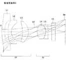
図1、図4、図7、図10、および図13は、本実施の形態の数値実施例1〜5に係る撮像レンズの概略構成を示す断面図である。いずれの数値実施例も基本的なレンズ構成は同様であるため、ここでは主に数値実施例1の概略断面図を参照しながら、本実施の形態に係る撮像レンズのレンズ構成について説明する。 1, 4, 7, 10, and 13 are cross-sectional views illustrating a schematic configuration of an imaging lens according to Numerical Examples 1 to 5 of the present embodiment. Since any of the numerical examples has the same basic lens configuration, the lens configuration of the imaging lens according to the present embodiment will be described mainly with reference to a schematic cross-sectional view of the numerical example 1.
図1に示すように、本実施の形態の撮像レンズは、物体側から像面側に向かって順に、正の屈折力を有する物体側レンズ群Gfと、開口絞りSTと、正の屈折力を有する像面側レンズ群Grとを配置して構成される。すなわち、本実施の形態の撮像レンズでは、開口絞りSTを挟んで、開口絞りSTよりも物体側に配置された物体側レンズ群Gf、および開口絞りSTよりも像面側に配置された像面側レンズ群Grが共に正の屈折力を有するレンズ群として構成される。 As shown in FIG. 1, the imaging lens of the present embodiment has an object side lens group Gf having a positive refractive power, an aperture stop ST, and a positive refractive power in order from the object side to the image plane side. And an image plane side lens group Gr. That is, in the imaging lens of the present embodiment, the object side lens group Gf disposed on the object side with respect to the aperture stop ST and the image plane disposed on the image plane side with respect to the aperture stop ST with the aperture stop ST interposed therebetween. Both side lens groups Gr are configured as lens groups having positive refractive power.
これら物体側レンズ群Gfおよび像面側レンズ群Grは次の各条件式を満足するように構成される。
5<Ff/f<12
0.5<Fr/f<2.5
但し、
f:レンズ系全体の焦点距離、
Ff:物体側レンズ群Gfの焦点距離、
Fr:像面側レンズ群Grの焦点距離、
である。The object side lens group Gf and the image plane side lens group Gr are configured to satisfy the following conditional expressions.
5 <Ff / f <12
0.5 <Fr / f <2.5
However,
f: focal length of the entire lens system,
Ff: focal length of the object side lens group Gf,
Fr: focal length of the image side lens group Gr,
It is.
このうち物体側レンズ群Gfは、物体側から像面側に向かって順に、正の屈折力を有する第1レンズL1と、負の屈折力を有する第2レンズL2と、正の屈折力を有する第3レンズL3とが配置されて構成される。 Among these, the object side lens group Gf has a first lens L1 having a positive refractive power, a second lens L2 having a negative refractive power, and a positive refractive power in order from the object side to the image plane side. A third lens L3 is arranged.
第1レンズL1は、光軸Xからレンズ周辺部に向かうにつれて負の屈折力が強くなる非球面形状に形成される。本実施の形態に係る撮像レンズにおいて第1レンズL1の屈折力は、光軸Xの近傍では正であり、レンズ周辺部では負となっている。この第1レンズL1は、物体側の面の曲率半径r1が正となり、像面側の面の曲率半径r2が負となる形状であって、光軸Xの近傍において両凸レンズとなる形状に形成される。なお、第1レンズL1の形状は当該形状に限定されるものではない。第1レンズL1の形状は、曲率半径r1および曲率半径r2が共に正となる形状であって、光軸Xの近傍において物体側に凸面を向けたメニスカスレンズとなる形状でもよい。数値実施例1および2は、第1レンズL1が、光軸Xの近傍において両凸レンズとなる形状の例であり、数値実施例3〜5は、第1レンズL1の形状が、光軸Xの近傍において物体側に凸面を向けたメニスカスレンズとなる形状の例である。 The first lens L1 is formed in an aspherical shape with a negative refractive power that increases from the optical axis X toward the lens periphery. In the imaging lens according to the present embodiment, the refractive power of the first lens L1 is positive in the vicinity of the optical axis X and negative in the lens periphery. The first lens L1 has a shape in which the curvature radius r1 of the object-side surface is positive and the curvature radius r2 of the image-side surface is negative, and is formed into a shape that becomes a biconvex lens in the vicinity of the optical axis X. Is done. The shape of the first lens L1 is not limited to this shape. The shape of the first lens L1 may be a shape in which the curvature radius r1 and the curvature radius r2 are both positive, and may be a meniscus lens having a convex surface facing the object side in the vicinity of the optical axis X. Numerical Examples 1 and 2 are examples in which the first lens L1 is a biconvex lens in the vicinity of the optical axis X. In Numerical Examples 3 to 5, the first lens L1 has the shape of the optical axis X. This is an example of a shape that becomes a meniscus lens having a convex surface facing the object side in the vicinity.
第2レンズL2は、光軸Xからレンズ周辺部に向かうにつれて負の屈折力が強くなる非球面形状に形成される。また、第2レンズL2は、物体側の面の曲率半径r3および像面側の面の曲率半径r4が共に正となる形状であって、光軸Xの近傍において物体側に凸面を向けたメニスカスレンズとなる形状に形成される。当該第2レンズL2において像面側の面は強い凹面となっている。なお、第2レンズL2の形状は当該形状に限定されるものではない。第2レンズL2の形状は、曲率半径r3が負となり、曲率半径r4が正となる形状、すなわち光軸Xの近傍において両凹レンズとなる形状でもよい。数値実施例1〜3および5は、第2レンズL2が、光軸Xの近傍において物体側に凸面を向けたメニスカスレンズとなる形状の例であり、数値実施例4は、第2レンズL2の形状が、光軸Xの近傍において両凹レンズとなる形状の例である。 The second lens L2 is formed in an aspherical shape in which the negative refractive power increases from the optical axis X toward the lens periphery. The second lens L2 has a meniscus shape in which the curvature radius r3 of the object-side surface and the curvature radius r4 of the image-side surface are both positive and have a convex surface facing the object side in the vicinity of the optical axis X. It is formed in a shape that becomes a lens. In the second lens L2, the image side surface is a strong concave surface. The shape of the second lens L2 is not limited to this shape. The shape of the second lens L2 may be a shape in which the radius of curvature r3 is negative and the radius of curvature r4 is positive, that is, a shape that is a biconcave lens in the vicinity of the optical axis X. Numerical Examples 1 to 3 and 5 are examples in which the second lens L2 is a meniscus lens having a convex surface facing the object side in the vicinity of the optical axis X. Numerical Example 4 is an example of the second lens L2. In this example, the shape is a biconcave lens in the vicinity of the optical axis X.
第1レンズL1および第2レンズL2は次の各条件式を満足する。
1.5<f1/f<7
2<f1/|f2|<8
但し、
f1:第1レンズL1の焦点距離、
f2:第2レンズL2の焦点距離、
である。The first lens L1 and the second lens L2 satisfy the following conditional expressions.
1.5 <f1 / f <7
2 <f1 / | f2 | <8
However,
f1: the focal length of the first lens L1,
f2: focal length of the second lens L2,
It is.
第3レンズL3は、物体側の面の曲率半径r5および像面側の面の曲率半径r6が共に負となる形状であって、光軸Xの近傍において物体側に凹面を向けたメニスカスレンズとなる形状に形成される。したがって、上記第2レンズL2と第3レンズL3とは、互いに凹面を向けた状態で配置されることになる。 The third lens L3 is a meniscus lens having a negative curvature radius r5 on the object side surface and a curvature radius r6 on the image side surface, the concave surface facing the object side in the vicinity of the optical axis X. Is formed into a shape. Therefore, the second lens L2 and the third lens L3 are arranged with their concave surfaces facing each other.
以上のように、物体側レンズ群Gfは第1レンズL1〜第3レンズL3の3枚のレンズから構成されている。これら第1レンズL1〜第3レンズL3は、さらに次の条件式を満足する。
|f2|<f1 且つ |f2|<f3As described above, the object-side lens group Gf includes three lenses, the first lens L1 to the third lens L3. The first lens L1 to the third lens L3 further satisfy the following conditional expression.
| F2 | <f1 and | f2 | <f3
撮像レンズの広角化を図りつつ諸収差を良好に補正するためには第1レンズL1と第2レンズL2との屈折力のバランスが重要になる。光学シミュレーションの結果、当該条件式として示されるように、第2レンズL2の屈折力を第1レンズL1の屈折力の2倍以上の大きさにすることで、撮像レンズの広角化と諸収差の良好な補正を好適に実現できることが判明した。このように第1レンズL1の屈折力を弱くすることは、撮像レンズの製造に際して生じるディセンタ(偏芯)やチルト等に対する結像性能の劣化に対する敏感度(製造誤差感度)を下げる観点からも有効である。 In order to satisfactorily correct various aberrations while widening the angle of the imaging lens, the balance of the refractive powers of the first lens L1 and the second lens L2 is important. As a result of the optical simulation, as shown as the conditional expression, by making the refractive power of the second lens L2 more than twice the refractive power of the first lens L1, the widening angle of the imaging lens and various aberrations are improved. It has been found that good correction can be suitably realized. Reducing the refractive power of the first lens L1 in this way is also effective from the viewpoint of lowering sensitivity (manufacturing error sensitivity) to deterioration of imaging performance with respect to decenter (decentering) and tilt generated during the manufacturing of the imaging lens. It is.
一方、像面側レンズ群Grを構成する第4レンズL4は、物体側の面の曲率半径r8が正となり、像面側の面の曲率半径r9が負となる形状であって、光軸Xの近傍において両凸レンズとなる形状に形成される。また、第5レンズL5は、物体側の面の曲率半径r10および像面側の面の曲率半径r11が共に負となる形状、すなわち光軸Xの近傍において物体側に凹面を向けたメニスカスレンズとなる形状に形成される。なお、第5レンズL5と像面IMとの間には、フィルタ10が配置される。フィルタ10は割愛することも可能である。 On the other hand, the fourth lens L4 constituting the image side lens group Gr has a shape in which the curvature radius r8 of the object side surface is positive and the curvature radius r9 of the image side surface is negative, and the optical axis X Is formed in a shape that becomes a biconvex lens in the vicinity of. The fifth lens L5 is a meniscus lens having a shape in which both the curvature radius r10 of the object side surface and the curvature radius r11 of the image side surface are negative, that is, a concave surface facing the object side in the vicinity of the optical axis X. Is formed into a shape. A
以上詳細に説明した第1レンズL1〜第5レンズL5は、次の各条件式を満足する材料で形成される。
40<νd1<70
40<νd2<70
40<νd3<70
40<νd4<70
20<νd5<35
但し、
νd1:第1レンズL1のアッベ数、
νd2:第2レンズL2のアッベ数、
νd3:第3レンズL3のアッベ数、
νd4:第4レンズL4のアッベ数、
νd5:第5レンズL5のアッベ数、
である。The first lens L1 to the fifth lens L5 described in detail above are formed of a material that satisfies the following conditional expressions.
40 <νd1 <70
40 <νd2 <70
40 <νd3 <70
40 <νd4 <70
20 <νd5 <35
However,
νd1: Abbe number of the first lens L1,
νd2: Abbe number of the second lens L2,
νd3: Abbe number of the third lens L3,
νd4: Abbe number of the fourth lens L4,
νd5: Abbe number of the fifth lens L5,
It is.
ところで、レンズの材料としては大きく分けて硝子系の材料とプラスチック系(樹脂系)の材料とがある。環境温度による焦点距離の変動を抑制したい場合や過酷な環境下での使用を想定した場合には、各レンズを硝子系の材料で形成することが望ましい。特に、車載カメラは高温下で使用されることが多く、また水や洗車傷に対する耐性も必須となることから硝子系の材料が好まれて使用されている。しかしながら、硝子系の材料はプラスチック系の材料に比較して一般的に高価である。携帯電話機やセキュリティカメラにおいては、製造コストと光学性能のバランスからプラスチック系の材料が多く使用されている。 By the way, the material of the lens is roughly classified into a glass-based material and a plastic-based (resin-based) material. When it is desired to suppress the variation of the focal length due to the environmental temperature or when it is assumed to be used in a harsh environment, it is desirable to form each lens with a glass-based material. In particular, in-vehicle cameras are often used at high temperatures, and since resistance to water and car wash scratches is essential, glass-based materials are preferred and used. However, glass-based materials are generally more expensive than plastic-based materials. In mobile phones and security cameras, plastic materials are often used because of the balance between manufacturing cost and optical performance.
そこで、撮像レンズの製造コストの一層の低減を図るためには、第1レンズL1〜第4レンズL4を、次の各条件式を満足する材料から形成することが望ましい。
50<νd1<60
50<νd2<60
50<νd3<60
50<νd4<60Therefore, in order to further reduce the manufacturing cost of the imaging lens, it is desirable to form the first lens L1 to the fourth lens L4 from materials that satisfy the following conditional expressions.
50 <νd1 <60
50 <νd2 <60
50 <νd3 <60
50 <νd4 <60
なお、上記各条件式の全てを満足する必要はなく、それぞれを単独に満足することにより、各条件式に対応する作用効果をそれぞれ得ることができる。 Note that it is not necessary to satisfy all of the above conditional expressions, and by satisfying each of the conditional expressions individually, it is possible to obtain the operational effects corresponding to the conditional expressions.
本実施の形態では各レンズのレンズ面を非球面で形成している。これらレンズ面に採用する非球面形状は、光軸方向の軸をZ、光軸に直交する方向の高さをH、円錐係数をk、非球面係数をA4、A6としたとき、次式により表される。
次に、本実施の形態に係る撮像レンズの数値実施例を示す。各数値実施例において、fはレンズ系全体の焦点距離を、FnoはFナンバーを、ωは半画角をそれぞれ示す。また、iは物体側より数えた面番号を示し、rは曲率半径を示し、dは光軸上のレンズ面間の距離(面間隔)を示し、ndはd線に対する屈折率を、νdはd線に対するアッベ数をそれぞれ示す。また、非球面の面には、面番号iの後に*(アスタリスク)の符号を付加して示すこととする。なお、第1レンズL1の物体側の面から像面IMまでの光軸上の面間隔の和(フィルタ10は空気換算長)をLaとして示す。 Next, numerical examples of the imaging lens according to the present embodiment will be shown. In each numerical example, f represents the focal length of the entire lens system, Fno represents the F number, and ω represents the half angle of view. In addition, i represents a surface number counted from the object side, r represents a radius of curvature, d represents a distance (surface interval) between lens surfaces on the optical axis, nd represents a refractive index with respect to the d-line, and νd represents The Abbe numbers with respect to the d line are shown respectively. An aspherical surface is indicated by adding a symbol of * (asterisk) after the surface number i. Note that the sum of the surface intervals on the optical axis from the object-side surface of the first lens L1 to the image plane IM (the
数値実施例1
基本的なレンズデータを以下に示す。
f=2.87mm、Fno=2.4、ω=85°
単位 mm
面データ
面番号i r d nd νd
(物面) ∞ ∞
1* 5.927 0.600 1.535 56.1(=νd1)
2* -372.607 0.496
3* 96.016 0.600 1.535 56.1(=νd2)
4* 1.854 1.979
5* -6.174 1.293 1.535 56.1(=νd3)
6* -2.498 0.840
7 (絞り) ∞ 0.346
8* 2.512 1.442 1.535 56.1(=νd4)
9* -1.879 0.100
10* -1.553 0.348 1.614 26.0(=νd5)
11* -5.309 0.700
12 ∞ 0.700 1.517 64.1
13 ∞ 1.523
(像面) ∞
Ff=23.96mm
Fr=4.43mm
f1=10.91mm
f2=-3.54mm
f3=6.98mm
f4=2.27mm
f5=-3.70mm
La=10.73mmNumerical example 1
Basic lens data is shown below.
f = 2.87mm, Fno = 2.4, ω = 85 °
Unit mm
Surface data Surface number ir d nd νd
(Surface) ∞ ∞
1 * 5.927 0.600 1.535 56.1 (= νd1)
2 * -372.607 0.496
3 * 96.016 0.600 1.535 56.1 (= νd2)
4 * 1.854 1.979
5 * -6.174 1.293 1.535 56.1 (= νd3)
6 * -2.498 0.840
7 (Aperture) ∞ 0.346
8 * 2.512 1.442 1.535 56.1 (= νd4)
9 * -1.879 0.100
10 * -1.553 0.348 1.614 26.0 (= νd5)
11 * -5.309 0.700
12 ∞ 0.700 1.517 64.1
13 ∞ 1.523
(Image plane) ∞
Ff = 23.96mm
Fr = 4.43mm
f1 = 10.91mm
f2 = -3.54mm
f3 = 6.98mm
f4 = 2.27mm
f5 = -3.70mm
La = 10.73mm
非球面データ
第1面
k=0.000,A4=-6.713E-03,A6=1.510E-04
第2面
k=0.000,A4=1.667E-02,A6=4.431E-04
第3面
k=0.000,A4=3.703E-02,A6=-3.694E-03
第4面
k=0.000,A4=1.016E-02,A6=-8.772E-03
第5面
k=0.000,A4=-6.026E-03,A6=5.570E-04
第6面
k=0.000,A4=8.672E-03,A6=-8.222E-04
第8面
k=0.000,A4=1.542E-02,A6=-3.746E-03
第9面
k=0.000,A4=3.297E-02,A6=-4.211E-03
第10面
k=0.000,A4=6.873E-02,A6=7.125E-03
第11面
k=0.000,A4=3.874E-02,A6=1.252E-02Aspheric data 1st surface k = 0.000, A4 = -6.713E-03, A6 = 1.510E-04
2nd surface k = 0.000, A4 = 1.667E-02, A6 = 4.431E-04
3rd surface k = 0.000, A4 = 3.703E-02, A6 = -3.694E-03
4th surface k = 0.000, A4 = 1.016E-02, A6 = -8.772E-03
5th surface k = 0.000, A4 = -6.026E-03, A6 = 5.570E-04
6th surface k = 0.000, A4 = 8.672E-03, A6 = -8.222E-04
8th surface k = 0.000, A4 = 1.542E-02, A6 = -3.746E-03
9th surface k = 0.000, A4 = 3.297E-02, A6 = -4.211E-03
10th surface k = 0.000, A4 = 6.873E-02, A6 = 7.125E-03
11th surface k = 0.000, A4 = 3.874E-02, A6 = 1.252E-02
各条件式の値を以下に示す。
f1/f=3.80
f1/|f2|=3.08
Ff/f=8.35
Fr/f=1.54
このように、本数値実施例1に係る撮像レンズは上記各条件式を満足する。また、第1レンズL1の物体側の面から像面IMまでの光軸上の面間隔の和Laは10.73mmであり、撮像レンズの小型化が好適に図られている。The value of each conditional expression is shown below.
f1 / f = 3.80
f1 / | f2 | = 3.08
Ff / f = 8.35
Fr / f = 1.54
Thus, the imaging lens according to Numerical Example 1 satisfies the above conditional expressions. Further, the sum La of the surface intervals on the optical axis from the object-side surface of the first lens L1 to the image plane IM is 10.73 mm, and the downsizing of the imaging lens is suitably achieved.
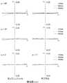
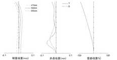
図2は、数値実施例1の撮像レンズについて、半画角ωに対応する横収差をタンジェンシャル方向とサジタル方向とに分けて示したものである(図5、図8、図11、および図14においても同じ)。また、図3は、数値実施例1の撮像レンズについて、球面収差(mm)、非点収差(mm)、および歪曲収差(%)を示したものである。非点収差図においてSはサジタル像面を、Tはタンジェンシャル像面をそれぞれ表す(図6、図9、図12、および図15においても同じ)。図2および図3に示されるように、本数値実施例1に係る撮像レンズによれば諸収差が良好に補正される。 FIG. 2 shows the lateral aberration corresponding to the half angle of view ω in the tangential direction and the sagittal direction for the imaging lens of Numerical Example 1 (FIGS. 5, 8, 11, and FIG. 2). 14 also). FIG. 3 shows spherical aberration (mm), astigmatism (mm), and distortion (%) for the imaging lens of Numerical Example 1. In the astigmatism diagrams, S represents a sagittal image plane, and T represents a tangential image plane (the same applies to FIGS. 6, 9, 12, and 15). As shown in FIGS. 2 and 3, the imaging lens according to Numerical Example 1 corrects various aberrations satisfactorily.
数値実施例2
基本的なレンズデータを以下に示す。
f=3.37mm、Fno=2.5、ω=69°
単位 mm
面データ
面番号i r d nd νd
(物面) ∞ ∞
1* 4.888 0.648 1.535 56.1(=νd1)
2* -1042.209 1.877
3* 15.994 0.600 1.535 56.1(=νd2)
4* 1.995 1.682
5* -5.093 0.690 1.535 56.1(=νd3)
6* -2.844 1.544
7 (絞り) ∞ 0.544
8* 2.200 1.434 1.535 56.1(=νd4)
9* -1.585 0.100
10* -1.454 0.346 1.614 26.0(=νd5)
11* -2.775 0.700
12 ∞ 0.700 1.517 64.1
13 ∞ 0.556
(像面) ∞
Ff=40.27mm
Fr=2.86mm
f1=9.10mm
f2=-4.32mm
f3=10.87mm
f4=1.98mm
f5=-5.53mm
La=11.18mmNumerical example 2
Basic lens data is shown below.
f = 3.37mm, Fno = 2.5, ω = 69 °
Unit mm
Surface data Surface number ir d nd νd
(Surface) ∞ ∞
1 * 4.888 0.648 1.535 56.1 (= νd1)
2 * -1042.209 1.877
3 * 15.994 0.600 1.535 56.1 (= νd2)
4 * 1.995 1.682
5 * -5.093 0.690 1.535 56.1 (= νd3)
6 * -2.844 1.544
7 (Aperture) ∞ 0.544
8 * 2.200 1.434 1.535 56.1 (= νd4)
9 * -1.585 0.100
10 * -1.454 0.346 1.614 26.0 (= νd5)
11 * -2.775 0.700
12 ∞ 0.700 1.517 64.1
13 ∞ 0.556
(Image plane) ∞
Ff = 40.27mm
Fr = 2.86mm
f1 = 9.10mm
f2 = -4.32mm
f3 = 10.87mm
f4 = 1.98mm
f5 = -5.53mm
La = 11.18mm
非球面データ
第1面
k=0.000,A4=-3.257E-03,A6=-1.093E-04
第2面
k=0.000,A4=3.640E-03,A6=3.788E-04
第3面
k=0.000,A4=3.108E-02,A6=-2.436E-03
第4面
k=0.000,A4=-1.158E-03,A6=-4.964E-03
第5面
k=0.000,A4=2.471E-02,A6=1.187E-04
第6面
k=0.000,A4=3.732E-02,A6=-4.911E-03
第8面
k=0.000,A4=-2.744E-02,A6=1.062E-02
第9面
k=0.000,A4=-9.543E-02,A6=5.957E-02
第10面
k=0.000,A4=-1.093E-02,A6=1.315E-02
第11面
k=0.000,A4=6.936E-02,A6=-2.130E-02Aspheric data 1st surface k = 0.000, A4 = -3.257E-03, A6 = -1.093E-04
2nd surface k = 0.000, A4 = 3.640E-03, A6 = 3.788E-04
3rd surface k = 0.000, A4 = 3.108E-02, A6 = -2.436E-03
4th surface k = 0.000, A4 = -1.158E-03, A6 = -4.964E-03
5th surface k = 0.000, A4 = 2.471E-02, A6 = 1.187E-04
6th surface k = 0.000, A4 = 3.732E-02, A6 = -4.911E-03
8th surface k = 0.000, A4 = -2.744E-02, A6 = 1.062E-02
9th surface k = 0.000, A4 = -9.543E-02, A6 = 5.957E-02
10th surface k = 0.000, A4 = -1.093E-02, A6 = 1.315E-02
11th surface k = 0.000, A4 = 6.936E-02, A6 = -2.130E-02
各条件式の値を以下に示す。
f1/f=2.70
f1/|f2|=2.11
Ff/f=11.95
Fr/f=0.85
このように、本数値実施例2に係る撮像レンズは上記各条件式を満足する。また、第1レンズL1の物体側の面から像面IMまでの光軸上の面間隔の和Laは11.18mmであり、撮像レンズの小型化が好適に図られている。The value of each conditional expression is shown below.
f1 / f = 2.70
f1 / | f2 | = 2.11
Ff / f = 11.95
Fr / f = 0.85
Thus, the imaging lens according to Numerical Example 2 satisfies the above conditional expressions. Further, the sum La of the surface intervals on the optical axis from the object-side surface of the first lens L1 to the image plane IM is 11.18 mm, and the downsizing of the imaging lens is suitably achieved.
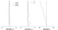
図5は、数値実施例2の撮像レンズについて、半画角ωに対応する横収差を示したものであり、図6は、球面収差(mm)、非点収差(mm)、および歪曲収差(%)をそれぞれ示したものである。図5および図6に示されるように、本数値実施例2に係る撮像レンズによっても諸収差が良好に補正される。 FIG. 5 shows lateral aberration corresponding to the half angle of view ω for the imaging lens of Numerical Example 2, and FIG. 6 shows spherical aberration (mm), astigmatism (mm), and distortion ( %). As shown in FIGS. 5 and 6, various aberrations are favorably corrected by the imaging lens according to Numerical Example 2 as well.
数値実施例3
基本的なレンズデータを以下に示す。
f=2.84mm、Fno=2.4、ω=85°
単位 mm
面データ
面番号i r d nd νd
(物面) ∞ ∞
1* 5.498 0.600 1.535 56.1(=νd1)
2* 22.066 0.606
3* 100.433 0.600 1.535 56.1(=νd2)
4* 1.948 2.326
5* -7.794 1.205 1.535 56.1(=νd3)
6* -2.488 1.051
7 (絞り) ∞ 0.381
8* 2.571 1.308 1.535 56.1(=νd4)
9* -1.929 0.100
10* -1.596 0.346 1.614 26.0(=νd5)
11* -6.276 0.700
12 ∞ 0.700 1.517 64.1
13 ∞ 1.552
(像面) ∞
Ff=15.69mm
Fr=4.77mm
f1=13.52mm
f2=-3.72mm
f3=6.33mm
f4=2.29mm
f5=-3.58mm
La=11.24mmNumerical Example 3
Basic lens data is shown below.
f = 2.84mm, Fno = 2.4, ω = 85 °
Unit mm
Surface data Surface number ir d nd νd
(Surface) ∞ ∞
1 * 5.498 0.600 1.535 56.1 (= νd1)
2 * 22.066 0.606
3 * 100.433 0.600 1.535 56.1 (= νd2)
4 * 1.948 2.326
5 * -7.794 1.205 1.535 56.1 (= νd3)
6 * -2.488 1.051
7 (Aperture) ∞ 0.381
8 * 2.571 1.308 1.535 56.1 (= νd4)
9 * -1.929 0.100
10 * -1.596 0.346 1.614 26.0 (= νd5)
11 * -6.276 0.700
12 ∞ 0.700 1.517 64.1
13 ∞ 1.552
(Image plane) ∞
Ff = 15.69mm
Fr = 4.77mm
f1 = 13.52mm
f2 = -3.72mm
f3 = 6.33mm
f4 = 2.29mm
f5 = -3.58mm
La = 11.24mm
非球面データ
第1面
k=0.000,A4=-6.442E-03,A6=1.142E-04
第2面
k=0.000,A4=1.344E-02,A6=6.217E-04
第3面
k=0.000,A4=3.626E-02,A6=-3.623E-03
第4面
k=0.000,A4=1.823E-02,A6=-8.231E-03
第5面
k=0.000,A4=-7.997E-03,A6=4.921E-04
第6面
k=0.000,A4=6.233E-03,A6=-1.225E-04
第8面
k=0.000,A4=1.622E-02,A6=-3.214E-03
第9面
k=0.000,A4=3.151E-02,A6=-3.623E-03
第10面
k=0.000,A4=6.891E-02,A6=4.085E-03
第11面
k=0.000,A4=4.243E-02,A6=1.005E-02Aspheric data 1st surface k = 0.000, A4 = -6.442E-03, A6 = 1.142E-04
2nd surface k = 0.000, A4 = 1.344E-02, A6 = 6.217E-04
3rd surface k = 0.000, A4 = 3.626E-02, A6 = -3.623E-03
4th surface k = 0.000, A4 = 1.823E-02, A6 = -8.231E-03
5th surface k = 0.000, A4 = -7.997E-03, A6 = 4.921E-04
6th surface k = 0.000, A4 = 6.233E-03, A6 = -1.225E-04
8th surface k = 0.000, A4 = 1.622E-02, A6 = -3.214E-03
9th surface k = 0.000, A4 = 3.151E-02, A6 = -3.623E-03
10th surface k = 0.000, A4 = 6.891E-02, A6 = 4.085E-03
11th surface k = 0.000, A4 = 4.243E-02, A6 = 1.005E-02
各条件式の値を以下に示す。
f1/f=4.76
f1/|f2|=3.63
Ff/f=5.52
Fr/f=1.68
このように、本数値実施例3に係る撮像レンズは上記各条件式を満足する。また、第1レンズL1の物体側の面から像面IMまでの光軸上の面間隔の和Laは11.24mmであり、撮像レンズの小型化が好適に図られている。The value of each conditional expression is shown below.
f1 / f = 4.76
f1 / | f2 | = 3.63
Ff / f = 5.52
Fr / f = 1.68
Thus, the imaging lens according to Numerical Example 3 satisfies the above conditional expressions. Further, the sum La of the surface intervals on the optical axis from the object-side surface of the first lens L1 to the image plane IM is 11.24 mm, and the image pickup lens is preferably downsized.
図8は、数値実施例3の撮像レンズについて、半画角ωに対応する横収差を示したものであり、図9は、球面収差(mm)、非点収差(mm)、および歪曲収差(%)をそれぞれ示したものである。図8および図9に示されるように、本数値実施例3に係る撮像レンズによっても諸収差が良好に補正される。 FIG. 8 shows lateral aberration corresponding to the half angle of view ω for the imaging lens of Numerical Example 3, and FIG. 9 shows spherical aberration (mm), astigmatism (mm), and distortion ( %). As shown in FIGS. 8 and 9, various aberrations are also satisfactorily corrected by the imaging lens according to Numerical Example 3 as well.
数値実施例4
基本的なレンズデータを以下に示す。
f=2.79mm、Fno=2.6、ω=85°
単位 mm
面データ
面番号i r d nd νd
(物面) ∞ ∞
1* 6.607 0.600 1.535 56.1(=νd1)
2* 17.743 0.640
3* -181.316 0.600 1.535 56.1(=νd2)
4* 1.759 2.152
5* -6.764 1.174 1.535 56.1(=νd3)
6* -2.383 1.259
7 (絞り) ∞ 0.466
8* 2.631 1.556 1.535 56.1(=νd4)
9* -1.886 0.100
10* -1.632 0.413 1.614 26.0(=νd5)
11* -7.979 0.700
12 ∞ 0.700 1.517 64.1
13 ∞ 1.921
(像面) ∞
Ff=29.38mm
Fr=4.98mm
f1=19.31mm
f2=-3.25mm
f3=6.29mm
f4=2.33mm
f5=-3.43mm
La=12.04mmNumerical Example 4
Basic lens data is shown below.
f = 2.79mm, Fno = 2.6, ω = 85 °
Unit mm
Surface data Surface number ir d nd νd
(Surface) ∞ ∞
1 * 6.607 0.600 1.535 56.1 (= νd1)
2 * 17.743 0.640
3 * -181.316 0.600 1.535 56.1 (= νd2)
4 * 1.759 2.152
5 * -6.764 1.174 1.535 56.1 (= νd3)
6 * -2.383 1.259
7 (Aperture) ∞ 0.466
8 * 2.631 1.556 1.535 56.1 (= νd4)
9 * -1.886 0.100
10 * -1.632 0.413 1.614 26.0 (= νd5)
11 * -7.979 0.700
12 ∞ 0.700 1.517 64.1
13 ∞ 1.921
(Image plane) ∞
Ff = 29.38mm
Fr = 4.98mm
f1 = 19.31mm
f2 = -3.25mm
f3 = 6.29mm
f4 = 2.33mm
f5 = -3.43mm
La = 12.04mm
非球面データ
第1面
k=0.000,A4=-5.650E-03,A6=1.290E-04
第2面
k=0.000,A4=1.315E-02,A6=2.930E-03
第3面
k=0.000,A4=3.840E-02,A6=-3.755E-03
第4面
k=0.000,A4=2.571E-03,A6=-7.844E-03
第5面
k=0.000,A4=-5.090E-03,A6=1.302E-03
第6面
k=0.000,A4=6.984E-03,A6=-3.398E-04
第8面
k=0.000,A4=7.993E-03,A6=-2.742E-04
第9面
k=0.000,A4=4.508E-02,A6=-4.936E-03
第10面
k=0.000,A4=7.993E-02,A6=-4.497E-03
第11面
k=0.000,A4=4.021E-02,A6=4.511E-03Aspheric data 1st surface k = 0.000, A4 = -5.650E-03, A6 = 1.290E-04
2nd surface k = 0.000, A4 = 1.315E-02, A6 = 2.930E-03
3rd surface k = 0.000, A4 = 3.840E-02, A6 = -3.755E-03
4th surface k = 0.000, A4 = 2.571E-03, A6 = -7.844E-03
5th surface k = 0.000, A4 = -5.090E-03, A6 = 1.302E-03
6th surface k = 0.000, A4 = 6.984E-03, A6 = -3.398E-04
8th surface k = 0.000, A4 = 7.993E-03, A6 = -2.742E-04
9th surface k = 0.000, A4 = 4.508E-02, A6 = -4.936E-03
10th surface k = 0.000, A4 = 7.993E-02, A6 = -4.497E-03
11th surface k = 0.000, A4 = 4.021E-02, A6 = 4.511E-03
各条件式の値を以下に示す。
f1/f=6.92
f1/|f2|=5.94
Ff/f=10.53
Fr/f=1.78
このように、本数値実施例4に係る撮像レンズは上記各条件式を満足する。また、第1レンズL1の物体側の面から像面IMまでの光軸上の面間隔の和Laは12.04mmであり、撮像レンズの小型化が好適に図られている。The value of each conditional expression is shown below.
f1 / f = 6.92
f1 / | f2 | = 5.94
Ff / f = 10.53
Fr / f = 1.78
Thus, the imaging lens according to Numerical Example 4 satisfies the above conditional expressions. Further, the sum La of the surface intervals on the optical axis from the object-side surface of the first lens L1 to the image plane IM is 12.04 mm, and the image pickup lens is suitably reduced in size.
図11は、数値実施例4の撮像レンズについて、半画角ωに対応する横収差を示したものであり、図12は、球面収差(mm)、非点収差(mm)、および歪曲収差(%)をそれぞれ示したものである。図11および図12に示されるように、本数値実施例4に係る撮像レンズによっても諸収差が良好に補正される。 FIG. 11 shows lateral aberration corresponding to the half angle of view ω for the imaging lens of Numerical Example 4. FIG. 12 shows spherical aberration (mm), astigmatism (mm), and distortion ( %). As shown in FIGS. 11 and 12, various aberrations are also satisfactorily corrected by the imaging lens according to Numerical Example 4 as well.
数値実施例5
基本的なレンズデータを以下に示す。
f=2.81mm、Fno=2.4、ω=85°
単位 mm
面データ
面番号i r d nd νd
(物面) ∞ ∞
1* 6.246 0.600 1.531 56.0(=νd1)
2* 19.624 0.694
3* 92.599 0.600 1.531 56.0(=νd2)
4* 1.957 2.227
5* -7.330 1.212 1.531 56.0(=νd3)
6* -2.483 1.117
7 (絞り) ∞ 0.328
8* 2.502 1.561 1.531 56.0(=νd4)
9* -1.902 0.100
10* -1.585 0.370 1.634 23.9(=νd5)
11* -5.886 0.700
12 ∞ 0.700 1.517 64.1
13 ∞ 1.529
(像面) ∞
Ff=19.85mm
Fr=4.73mm
f1=16.99mm
f2=-3.77mm
f3=6.51mm
f4=2.32mm
f5=-3.54mm
La=11.50mmNumerical Example 5
Basic lens data is shown below.
f = 2.81mm, Fno = 2.4, ω = 85 °
Unit mm
Surface data Surface number ir d nd νd
(Surface) ∞ ∞
1 * 6.246 0.600 1.531 56.0 (= νd1)
2 * 19.624 0.694
3 * 92.599 0.600 1.531 56.0 (= νd2)
4 * 1.957 2.227
5 * -7.330 1.212 1.531 56.0 (= νd3)
6 * -2.483 1.117
7 (Aperture) ∞ 0.328
8 * 2.502 1.561 1.531 56.0 (= νd4)
9 * -1.902 0.100
10 * -1.585 0.370 1.634 23.9 (= νd5)
11 * -5.886 0.700
12 ∞ 0.700 1.517 64.1
13 ∞ 1.529
(Image plane) ∞
Ff = 19.85mm
Fr = 4.73mm
f1 = 16.99mm
f2 = -3.77mm
f3 = 6.51mm
f4 = 2.32mm
f5 = -3.54mm
La = 11.50mm
非球面データ
第1面
k=0.000,A4=-6.122E-03,A6=1.325E-04
第2面
k=0.000,A4=1.089E-02,A6=1.092E-03
第3面
k=0.000,A4=3.432E-02,A6=-3.574E-03
第4面
k=0.000,A4=1.645E-02,A6=-8.742E-03
第5面
k=0.000,A4=-6.754E-03,A6=5.487E-04
第6面
k=0.000,A4=6.659E-03,A6=-1.220E-04
第8面
k=0.000,A4=1.369E-02,A6=-3.183E-03
第9面
k=0.000,A4=3.005E-02,A6=-3.680E-03
第10面
k=0.000,A4=6.832E-02,A6=2.619E-03
第11面
k=0.000,A4=4.299E-02,A6=8.764E-03Aspheric data 1st surface k = 0.000, A4 = -6.122E-03, A6 = 1.325E-04
2nd surface k = 0.000, A4 = 1.089E-02, A6 = 1.092E-03
3rd surface k = 0.000, A4 = 3.432E-02, A6 = -3.574E-03
4th surface k = 0.000, A4 = 1.645E-02, A6 = -8.742E-03
5th surface k = 0.000, A4 = -6.754E-03, A6 = 5.487E-04
6th surface k = 0.000, A4 = 6.659E-03, A6 = -1.220E-04
8th surface k = 0.000, A4 = 1.369E-02, A6 = -3.183E-03
9th surface k = 0.000, A4 = 3.005E-02, A6 = -3.680E-03
10th surface k = 0.000, A4 = 6.832E-02, A6 = 2.619E-03
11th surface k = 0.000, A4 = 4.299E-02, A6 = 8.764E-03
各条件式の値を以下に示す。
f1/f=6.05
f1/|f2|=4.51
Ff/f=7.06
Fr/f=1.68
このように、本数値実施例5に係る撮像レンズは上記各条件式を満足する。また、第1レンズL1の物体側の面から像面IMまでの光軸上の面間隔の和Laは11.50mmであり、撮像レンズの小型化が好適に図られている。The value of each conditional expression is shown below.
f1 / f = 6.05
f1 / | f2 | = 4.51
Ff / f = 7.06
Fr / f = 1.68
Thus, the imaging lens according to Numerical Example 5 satisfies the above conditional expressions. Further, the sum La of the surface intervals on the optical axis from the object-side surface of the first lens L1 to the image plane IM is 11.50 mm, and the downsizing of the imaging lens is suitably achieved.
図14は、数値実施例5の撮像レンズについて、半画角ωに対応する横収差を示したものであり、図15は、球面収差(mm)、非点収差(mm)、および歪曲収差(%)をそれぞれ示したものである。図14および図15に示されるように、本数値実施例5に係る撮像レンズによっても諸収差が良好に補正される。 FIG. 14 shows lateral aberration corresponding to the half angle of view ω for the imaging lens of Numerical Example 5, and FIG. 15 shows spherical aberration (mm), astigmatism (mm), and distortion ( %). As shown in FIGS. 14 and 15, various aberrations are also favorably corrected by the imaging lens according to Numerical Example 5.
以上説明した本実施の形態に係る撮像レンズによれば、130°以上の画角(2ω)を実現することができる。ちなみに数値実施例1〜5の撮像レンズの画角は138°〜170°の広い画角を実現している。 With the imaging lens according to the present embodiment described above, an angle of view (2ω) of 130 ° or more can be realized. Incidentally, the angle of view of the imaging lenses of Numerical Examples 1 to 5 realizes a wide angle of view of 138 ° to 170 °.
なお、上記各数値実施例では各レンズの面を非球面で形成したが、撮像レンズの全長や要求される光学性能に余裕があるのであれば、撮像レンズを構成するレンズ面の一部を球面で形成するようにしてもよい。 In each numerical example, the surface of each lens is formed as an aspherical surface. However, if there is a margin in the overall length of the imaging lens and the required optical performance, a part of the lens surface constituting the imaging lens is a spherical surface. You may make it form in.
したがって、本実施の形態に係る撮像レンズを、携帯電話機、デジタルスティルカメラ、携帯情報端末、セキュリティカメラ、車載カメラ、ネットワークカメラ等の撮像光学系に適用した場合、広角でありながらも収差が良好に補正された小型のカメラを提供することができる。 Therefore, when the imaging lens according to the present embodiment is applied to an imaging optical system such as a mobile phone, a digital still camera, a portable information terminal, a security camera, an in-vehicle camera, and a network camera, the aberration is excellent even though the angle is wide. A corrected small camera can be provided.
本発明は、撮像レンズとして広い撮影画角とともに良好な収差補正能力が要求される機器、例えば携帯電話機やセキュリティカメラ、車載カメラ等の機器に搭載される撮像レンズに適用することができる。 The present invention can be applied to an imaging lens mounted on a device such as a mobile phone, a security camera, or an on-vehicle camera that requires a wide aberration and a wide aberration for viewing as an imaging lens.
Gf 物体側レンズ群
Gr 像面側レンズ群
ST 開口絞り
L1 第1レンズ
L2 第2レンズ
L3 第3レンズ
L4 第4レンズ
L5 第5レンズ
10 フィルタGf Object side lens group Gr Image surface side lens group ST Aperture stop L1 First lens L2 Second lens L3 Third lens L4 Fourth lens
Claims (7)
Translated fromJapanese前記物体側レンズ群は、正の屈折力を有する第1レンズと、負の屈折力を有する第2レンズと、正の屈折力を有する第3レンズとから構成され、
前記像面側レンズ群は、正の屈折力を有する第4レンズと、負の屈折力を有する第5レンズとから構成され、
前記第1レンズは、光軸からレンズ周辺部に向かうにつれて負の屈折力が強くなる非球面形状に形成されるとともに、曲率半径が正となる物体側の面を有し、
前記第1レンズの焦点距離をf1、前記第2レンズの焦点距離をf2、前記第3レンズの焦点距離をf3、前記第1レンズのアッベ数をνd1、前記第2レンズのアッベ数をνd2、前記第3レンズのアッベ数をνd3、前記第4レンズのアッベ数をνd4、前記第5レンズのアッベ数をνd5としたとき、
|f2|<f1 且つ |f2|<f3
40<νd1<70
40<νd2<70
40<νd3<70
40<νd4<70
20<νd5<35
を満足する撮像レンズ。In order from the object side to the image plane side, an object side lens group having a positive refractive power, an aperture, and an image plane side lens group having a positive refractive power are arranged,
The object side lens group includes a first lens having a positive refractive power, a second lens having a negative refractive power, and a third lens having a positive refractive power,
The image surface side lens group includes a fourth lens having a positive refractive power and a fifth lens having a negative refractive power,
The first lens is formed in an aspherical shape in which negative refractive power increases as it goes from the optical axis toward the lens periphery, and has an object-side surface with a positive curvature radius.
The focal length of the first lens is f1, the focal length of the second lens is f2, the focal length of the third lens is f3, the Abbe number of the first lens is νd1, and the Abbe number of the second lens is νd2. When the Abbe number of the third lens is νd3, the Abbe number of the fourth lens is νd4, and the Abbe number of the fifth lens is νd5,
| F2 | <f1 and | f2 | <f3
40 <νd1 <70
40 <νd2 <70
40 <νd3 <70
40 <νd4 <70
20 <νd5 <35
An imaging lens that satisfies the requirements.
前記第3レンズは、曲率半径が共に負となる物体側の面および像面側の面を有する、請求項1に記載の撮像レンズ。The second lens is formed in an aspheric shape having a refractive power that increases from the optical axis toward the lens periphery, and has a surface on the image plane side having a positive curvature radius,
2. The imaging lens according to claim 1, wherein the third lens has an object-side surface and an image-side surface both of which have a negative curvature radius.
前記第5レンズは、曲率半径が共に負となる物体側の面および像面側の面を有する、請求項1または2に記載の撮像レンズ。The fourth lens has an object side surface having a positive curvature radius and an image surface side surface having a negative curvature radius,
The imaging lens according to claim 1, wherein the fifth lens has an object-side surface and an image-side surface both having a negative curvature radius.
1.5<f1/f<7
を満足する請求項1〜3のいずれか一項に記載の撮像レンズ。When the focal length of the entire lens system is f,
1.5 <f1 / f <7
The imaging lens according to any one of claims 1 to 3, which satisfies:
を満足する請求項1〜4のいずれか一項に記載の撮像レンズ。2 <f1 / | f2 | <8
The imaging lens according to any one of claims 1 to 4, which satisfies:
5<Ff/f<12
を満足する請求項1〜5のいずれか一項に記載の撮像レンズ。When the focal length of the entire lens system is f and the focal length of the object side lens group is Ff,
5 <Ff / f <12
The imaging lens according to any one of claims 1 to 5, which satisfies:
0.5<Fr/f<2.5
を満足する請求項1〜6のいずれか一項に記載の撮像レンズ。When the focal length of the entire lens system is f and the focal length of the image plane side lens unit is Fr,
0.5 <Fr / f <2.5
The imaging lens according to any one of claims 1 to 6, which satisfies:
Priority Applications (3)
| Application Number | Priority Date | Filing Date | Title |
|---|---|---|---|
| JP2013038345AJP6048882B2 (en) | 2013-02-28 | 2013-02-28 | Imaging lens |
| CN2013203766545UCN203324564U (en) | 2013-02-28 | 2013-06-27 | Shooting lens |
| US14/183,676US9291801B2 (en) | 2013-02-28 | 2014-02-19 | Imaging lens |
Applications Claiming Priority (1)
| Application Number | Priority Date | Filing Date | Title |
|---|---|---|---|
| JP2013038345AJP6048882B2 (en) | 2013-02-28 | 2013-02-28 | Imaging lens |
Publications (2)
| Publication Number | Publication Date |
|---|---|
| JP2014164287A JP2014164287A (en) | 2014-09-08 |
| JP6048882B2true JP6048882B2 (en) | 2016-12-21 |
Family
ID=49663901
Family Applications (1)
| Application Number | Title | Priority Date | Filing Date |
|---|---|---|---|
| JP2013038345AExpired - Fee RelatedJP6048882B2 (en) | 2013-02-28 | 2013-02-28 | Imaging lens |
Country Status (3)
| Country | Link |
|---|---|
| US (1) | US9291801B2 (en) |
| JP (1) | JP6048882B2 (en) |
| CN (1) | CN203324564U (en) |
Families Citing this family (51)
| Publication number | Priority date | Publication date | Assignee | Title |
|---|---|---|---|---|
| KR101634516B1 (en) | 2013-06-13 | 2016-06-28 | 코어포토닉스 리미티드 | Dual aperture zoom digital camera |
| JP2016523389A (en) | 2013-07-04 | 2016-08-08 | コアフォトニクス リミテッド | Compact telephoto lens assembly |
| US9857568B2 (en) | 2013-07-04 | 2018-01-02 | Corephotonics Ltd. | Miniature telephoto lens assembly |
| US9392188B2 (en) | 2014-08-10 | 2016-07-12 | Corephotonics Ltd. | Zoom dual-aperture camera with folded lens |
| CN112433331B (en) | 2015-01-03 | 2022-07-08 | 核心光电有限公司 | Miniature telephoto lens module and camera using the same |
| KR20160089743A (en)* | 2015-01-20 | 2016-07-28 | 삼성전자주식회사 | Imaging lens and imaging apparatus including the same |
| TWI545365B (en) | 2015-02-17 | 2016-08-11 | 大立光電股份有限公司 | Image lens group, image capturing device and electronic device |
| CN106772927B (en)* | 2015-11-20 | 2019-10-01 | 大立光电股份有限公司 | Imaging optical lens assembly, image capturing device and electronic device |
| CN108351495B (en) | 2015-11-20 | 2020-12-11 | 索尼公司 | Imaging lens |
| CN108292025B (en)* | 2015-11-20 | 2021-03-09 | 索尼公司 | Imaging lens |
| US10558023B2 (en) | 2016-09-14 | 2020-02-11 | Shenzhen Royole Technologies Co., Ltd. | Optical system and head-mounted display apparatus using same |
| TWI616678B (en) | 2016-12-20 | 2018-03-01 | 大立光電股份有限公司 | Image capturing lens system, image capturing apparatus and electronic device |
| CN106597641B (en)* | 2017-01-22 | 2022-10-18 | 东莞市宇瞳光学科技股份有限公司 | Small-sized low-cost 4MP athermal prime lens |
| TWI613480B (en)* | 2017-02-08 | 2018-02-01 | 大立光電股份有限公司 | Optical imaging system, imaging apparatus and electronic device |
| KR102212611B1 (en) | 2017-02-23 | 2021-02-05 | 코어포토닉스 리미티드 | Folded camera lens designs |
| TWI629501B (en)* | 2017-04-28 | 2018-07-11 | 聲遠精密光學股份有限公司 | Wide angle imaging lens assembly |
| CN107329235B (en)* | 2017-07-31 | 2022-11-22 | 浙江舜宇光学有限公司 | Imaging lens |
| WO2019093377A1 (en) | 2017-11-10 | 2019-05-16 | マクセル株式会社 | Imaging lens system and imaging device |
| TWI633361B (en) | 2017-11-15 | 2018-08-21 | 大立光電股份有限公司 | Optical imaging lens assembly, image capturing unit and electronic device |
| CN113189746B (en)* | 2017-12-08 | 2022-09-02 | 大立光电股份有限公司 | Electronic device |
| TWI652520B (en) | 2018-03-02 | 2019-03-01 | 大立光電股份有限公司 | Electronic device |
| JP7149095B2 (en)* | 2018-04-05 | 2022-10-06 | 東京晨美光学電子株式会社 | imaging lens |
| KR20250048118A (en)* | 2018-05-14 | 2025-04-07 | 코어포토닉스 리미티드 | Folded camera lens designs |
| CN110927939A (en)* | 2018-09-20 | 2020-03-27 | 南昌欧菲精密光学制品有限公司 | Optical imaging system, image capturing module and electronic device |
| CN111323890B (en)* | 2018-12-13 | 2021-10-26 | 宁波舜宇车载光学技术有限公司 | Optical lens and imaging apparatus including the same |
| CN111323889B (en)* | 2018-12-13 | 2021-08-03 | 宁波舜宇车载光学技术有限公司 | Optical lens and imaging apparatus |
| US11336830B2 (en) | 2019-01-03 | 2022-05-17 | Corephotonics Ltd. | Multi-aperture cameras with at least one two state zoom camera |
| WO2021033047A1 (en) | 2019-08-21 | 2021-02-25 | Corephotonics Ltd. | Low total track length for large sensor format |
| US12072609B2 (en) | 2019-09-24 | 2024-08-27 | Corephotonics Ltd. | Slim pop-out cameras and lenses for such cameras |
| CN110609379B (en)* | 2019-10-29 | 2021-06-25 | 长春理工大学 | Dual-channel common lens optical system |
| US11656538B2 (en) | 2019-11-25 | 2023-05-23 | Corephotonics Ltd. | Folded zoom camera module with adaptive aperture |
| US11689708B2 (en) | 2020-01-08 | 2023-06-27 | Corephotonics Ltd. | Multi-aperture zoom digital cameras and methods of using same |
| JP7483451B2 (en) | 2020-03-25 | 2024-05-15 | キヤノン株式会社 | Optical system and imaging device |
| US11770609B2 (en) | 2020-05-30 | 2023-09-26 | Corephotonics Ltd. | Systems and methods for obtaining a super macro image |
| KR102765964B1 (en) | 2020-07-22 | 2025-02-07 | 코어포토닉스 리미티드 | Folded camera lens design |
| CN119414645A (en) | 2020-07-31 | 2025-02-11 | 核心光电有限公司 | camera |
| EP4127788A4 (en) | 2020-09-18 | 2024-06-19 | Corephotonics Ltd. | Pop-out zoom camera |
| JP7553093B2 (en)* | 2020-10-30 | 2024-09-18 | 創太 清水 | Imaging optical system and imaging device |
| US12271105B2 (en) | 2020-11-05 | 2025-04-08 | Corephotonics Ltd. | Scanning Tele camera based on two prism field of view scanning |
| KR20250008791A (en) | 2020-12-01 | 2025-01-15 | 코어포토닉스 리미티드 | Folded camera with continuously adaptive zoom factor |
| CN112379509B (en)* | 2020-12-14 | 2022-06-10 | 天津欧菲光电有限公司 | Optical system, camera module, electronic equipment and automobile |
| CN117425062A (en) | 2021-01-25 | 2024-01-19 | 核心光电有限公司 | Lens system for compact digital camera |
| JP2022114767A (en)* | 2021-01-27 | 2022-08-08 | キヤノン株式会社 | Optical systems, imaging devices, in-vehicle systems and mobile devices |
| JP2022114764A (en)* | 2021-01-27 | 2022-08-08 | キヤノン株式会社 | Optical systems, imaging devices, in-vehicle systems and mobile devices |
| WO2022200965A1 (en) | 2021-03-22 | 2022-09-29 | Corephotonics Ltd. | Folded cameras with continuously adaptive zoom factor |
| KR20240012438A (en) | 2021-06-23 | 2024-01-29 | 코어포토닉스 리미티드 | Compact folded tele camera |
| KR102685591B1 (en) | 2021-09-23 | 2024-07-15 | 코어포토닉스 리미티드 | Large aperture continuous zoom folded telecamera |
| CN119414565A (en) | 2021-11-02 | 2025-02-11 | 核心光电有限公司 | Camera module and mobile device |
| CN120315167A (en) | 2021-12-14 | 2025-07-15 | 核心光电有限公司 | Large aperture compact scan telephoto camera |
| US12348870B2 (en) | 2022-04-09 | 2025-07-01 | Corephotonics Ltd. | Spin-out 360-degree camera for smartphone |
| US12368960B2 (en) | 2022-08-05 | 2025-07-22 | Corephotonics Ltd. | Systems and methods for zoom digital camera with automatic adjustable zoom field of view |
Family Cites Families (11)
| Publication number | Priority date | Publication date | Assignee | Title |
|---|---|---|---|---|
| JP2004354572A (en)* | 2003-05-28 | 2004-12-16 | Minolta Co Ltd | Imaging apparatus |
| JP4197994B2 (en)* | 2003-06-19 | 2008-12-17 | コニカミノルタオプト株式会社 | Imaging device |
| WO2007063891A1 (en)* | 2005-12-02 | 2007-06-07 | Nikon Corporation | Fish-eye lens and imaging device |
| JP5064154B2 (en)* | 2007-09-07 | 2012-10-31 | 日本電産ニッシン株式会社 | Super wide angle lens |
| KR101431548B1 (en)* | 2008-07-22 | 2014-08-19 | 삼성전자주식회사 | Lens optical system |
| JP2010243711A (en)* | 2009-04-03 | 2010-10-28 | Ricoh Co Ltd | Wide angle lens and imaging device |
| JP5330202B2 (en) | 2009-11-20 | 2013-10-30 | 富士フイルム株式会社 | Imaging lens and imaging apparatus |
| JP2011141396A (en)* | 2010-01-06 | 2011-07-21 | Tamron Co Ltd | Imaging lens, camera module, and imaging apparatus |
| US8508649B2 (en)* | 2011-02-14 | 2013-08-13 | DigitalOptics Corporation Europe Limited | Compact distorted zoom lens for small angle of view |
| TWI437311B (en)* | 2011-04-08 | 2014-05-11 | Largan Precision Co | Optical lens assembly for image taking |
| JP2013025202A (en)* | 2011-07-22 | 2013-02-04 | Konica Minolta Advanced Layers Inc | Image pickup lens and image pickup apparatus |
- 2013
- 2013-02-28JPJP2013038345Apatent/JP6048882B2/ennot_activeExpired - Fee Related
- 2013-06-27CNCN2013203766545Upatent/CN203324564U/ennot_activeExpired - Lifetime
- 2014
- 2014-02-19USUS14/183,676patent/US9291801B2/enactiveActive
Also Published As
| Publication number | Publication date |
|---|---|
| US9291801B2 (en) | 2016-03-22 |
| CN203324564U (en) | 2013-12-04 |
| JP2014164287A (en) | 2014-09-08 |
| US20140240853A1 (en) | 2014-08-28 |
Similar Documents
| Publication | Publication Date | Title |
|---|---|---|
| JP6048882B2 (en) | Imaging lens | |
| JP6128673B2 (en) | Imaging lens | |
| JP6684033B2 (en) | Imaging lens | |
| CN108508573B (en) | Camera lens | |
| JP6047701B2 (en) | Imaging lens | |
| JP6680445B2 (en) | Imaging lens | |
| JP5754670B2 (en) | Imaging lens | |
| JP5143595B2 (en) | Imaging lens and imaging apparatus | |
| JP5651861B2 (en) | Imaging lens | |
| JP6029111B2 (en) | Imaging lens | |
| JP5761602B2 (en) | Imaging lens | |
| JP6145887B2 (en) | Imaging lens and imaging apparatus | |
| JP6066424B2 (en) | Imaging lens and imaging apparatus | |
| JP2009092798A (en) | Imaging lens and imaging device | |
| JP6646128B2 (en) | Imaging lens | |
| CN104583833A (en) | Imaging lens, and imaging device equipped with same | |
| JP2019045665A (en) | Image capturing lens | |
| JP6664853B2 (en) | Imaging lens | |
| JP2009145809A (en) | Image pickup lens and image pickup apparatus | |
| JP5568732B2 (en) | Imaging lens | |
| JP5688562B2 (en) | Imaging lens | |
| JP6145888B2 (en) | Imaging lens and imaging apparatus | |
| WO2013018748A1 (en) | Imaging lens | |
| JP5839357B2 (en) | Imaging lens | |
| JP5308915B2 (en) | Imaging lens |
Legal Events
| Date | Code | Title | Description |
|---|---|---|---|
| A621 | Written request for application examination | Free format text:JAPANESE INTERMEDIATE CODE: A621 Effective date:20160222 | |
| A521 | Request for written amendment filed | Free format text:JAPANESE INTERMEDIATE CODE: A821 Effective date:20160222 | |
| TRDD | Decision of grant or rejection written | ||
| A01 | Written decision to grant a patent or to grant a registration (utility model) | Free format text:JAPANESE INTERMEDIATE CODE: A01 Effective date:20161109 | |
| A61 | First payment of annual fees (during grant procedure) | Free format text:JAPANESE INTERMEDIATE CODE: A61 Effective date:20161111 | |
| R150 | Certificate of patent or registration of utility model | Ref document number:6048882 Country of ref document:JP Free format text:JAPANESE INTERMEDIATE CODE: R150 | |
| S111 | Request for change of ownership or part of ownership | Free format text:JAPANESE INTERMEDIATE CODE: R313115 | |
| R371 | Transfer withdrawn | Free format text:JAPANESE INTERMEDIATE CODE: R371 | |
| S111 | Request for change of ownership or part of ownership | Free format text:JAPANESE INTERMEDIATE CODE: R313117 | |
| R350 | Written notification of registration of transfer | Free format text:JAPANESE INTERMEDIATE CODE: R350 | |
| S531 | Written request for registration of change of domicile | Free format text:JAPANESE INTERMEDIATE CODE: R313531 | |
| R350 | Written notification of registration of transfer | Free format text:JAPANESE INTERMEDIATE CODE: R350 | |
| R250 | Receipt of annual fees | Free format text:JAPANESE INTERMEDIATE CODE: R250 | |
| R250 | Receipt of annual fees | Free format text:JAPANESE INTERMEDIATE CODE: R250 | |
| S111 | Request for change of ownership or part of ownership | Free format text:JAPANESE INTERMEDIATE CODE: R313113 | |
| R371 | Transfer withdrawn | Free format text:JAPANESE INTERMEDIATE CODE: R371 | |
| S111 | Request for change of ownership or part of ownership | Free format text:JAPANESE INTERMEDIATE CODE: R313113 | |
| R350 | Written notification of registration of transfer | Free format text:JAPANESE INTERMEDIATE CODE: R350 | |
| R250 | Receipt of annual fees | Free format text:JAPANESE INTERMEDIATE CODE: R250 | |
| R250 | Receipt of annual fees | Free format text:JAPANESE INTERMEDIATE CODE: R250 | |
| R250 | Receipt of annual fees | Free format text:JAPANESE INTERMEDIATE CODE: R250 | |
| LAPS | Cancellation because of no payment of annual fees |