JP6048199B2 - Vehicle lighting device - Google Patents
Vehicle lighting deviceDownload PDFInfo
- Publication number
- JP6048199B2 JP6048199B2JP2013029269AJP2013029269AJP6048199B2JP 6048199 B2JP6048199 B2JP 6048199B2JP 2013029269 AJP2013029269 AJP 2013029269AJP 2013029269 AJP2013029269 AJP 2013029269AJP 6048199 B2JP6048199 B2JP 6048199B2
- Authority
- JP
- Japan
- Prior art keywords
- vehicle
- irradiation
- headlamp
- state
- inter
- Prior art date
- Legal status (The legal status is an assumption and is not a legal conclusion. Google has not performed a legal analysis and makes no representation as to the accuracy of the status listed.)
- Expired - Fee Related
Links
- 238000001514detection methodMethods0.000claimsdescription21
- 238000005286illuminationMethods0.000claimsdescription21
- 230000003287optical effectEffects0.000claimsdescription14
- 230000001133accelerationEffects0.000claimsdescription6
- 230000004313glareEffects0.000claimsdescription4
- 230000007423decreaseEffects0.000claims1
- 238000000034methodMethods0.000description28
- 230000004048modificationEffects0.000description13
- 238000012986modificationMethods0.000description13
- 238000010586diagramMethods0.000description12
- 230000001678irradiating effectEffects0.000description6
- 230000000903blocking effectEffects0.000description2
- 230000000694effectsEffects0.000description2
- 239000011521glassSubstances0.000description2
- 238000012538light obscurationMethods0.000description1
- 230000000116mitigating effectEffects0.000description1
Images


Classifications
- B—PERFORMING OPERATIONS; TRANSPORTING
- B60—VEHICLES IN GENERAL
- B60Q—ARRANGEMENT OF SIGNALLING OR LIGHTING DEVICES, THE MOUNTING OR SUPPORTING THEREOF OR CIRCUITS THEREFOR, FOR VEHICLES IN GENERAL
- B60Q1/00—Arrangement of optical signalling or lighting devices, the mounting or supporting thereof or circuits therefor
- B60Q1/02—Arrangement of optical signalling or lighting devices, the mounting or supporting thereof or circuits therefor the devices being primarily intended to illuminate the way ahead or to illuminate other areas of way or environments
- B60Q1/04—Arrangement of optical signalling or lighting devices, the mounting or supporting thereof or circuits therefor the devices being primarily intended to illuminate the way ahead or to illuminate other areas of way or environments the devices being headlights
- B60Q1/14—Arrangement of optical signalling or lighting devices, the mounting or supporting thereof or circuits therefor the devices being primarily intended to illuminate the way ahead or to illuminate other areas of way or environments the devices being headlights having dimming means
- B60Q1/1415—Dimming circuits
- B60Q1/1423—Automatic dimming circuits, i.e. switching between high beam and low beam due to change of ambient light or light level in road traffic
- B60Q1/143—Automatic dimming circuits, i.e. switching between high beam and low beam due to change of ambient light or light level in road traffic combined with another condition, e.g. using vehicle recognition from camera images or activation of wipers
- B—PERFORMING OPERATIONS; TRANSPORTING
- B60—VEHICLES IN GENERAL
- B60Q—ARRANGEMENT OF SIGNALLING OR LIGHTING DEVICES, THE MOUNTING OR SUPPORTING THEREOF OR CIRCUITS THEREFOR, FOR VEHICLES IN GENERAL
- B60Q1/00—Arrangement of optical signalling or lighting devices, the mounting or supporting thereof or circuits therefor
- B60Q1/02—Arrangement of optical signalling or lighting devices, the mounting or supporting thereof or circuits therefor the devices being primarily intended to illuminate the way ahead or to illuminate other areas of way or environments
- B60Q1/04—Arrangement of optical signalling or lighting devices, the mounting or supporting thereof or circuits therefor the devices being primarily intended to illuminate the way ahead or to illuminate other areas of way or environments the devices being headlights
- B60Q1/06—Arrangement of optical signalling or lighting devices, the mounting or supporting thereof or circuits therefor the devices being primarily intended to illuminate the way ahead or to illuminate other areas of way or environments the devices being headlights adjustable, e.g. remotely-controlled from inside vehicle
- B60Q1/08—Arrangement of optical signalling or lighting devices, the mounting or supporting thereof or circuits therefor the devices being primarily intended to illuminate the way ahead or to illuminate other areas of way or environments the devices being headlights adjustable, e.g. remotely-controlled from inside vehicle automatically
- B60Q1/085—Arrangement of optical signalling or lighting devices, the mounting or supporting thereof or circuits therefor the devices being primarily intended to illuminate the way ahead or to illuminate other areas of way or environments the devices being headlights adjustable, e.g. remotely-controlled from inside vehicle automatically due to special conditions, e.g. adverse weather, type of road, badly illuminated road signs or potential dangers
- B—PERFORMING OPERATIONS; TRANSPORTING
- B60—VEHICLES IN GENERAL
- B60Q—ARRANGEMENT OF SIGNALLING OR LIGHTING DEVICES, THE MOUNTING OR SUPPORTING THEREOF OR CIRCUITS THEREFOR, FOR VEHICLES IN GENERAL
- B60Q2300/00—Indexing codes for automatically adjustable headlamps or automatically dimmable headlamps
- B60Q2300/05—Special features for controlling or switching of the light beam
- B60Q2300/056—Special anti-blinding beams, e.g. a standard beam is chopped or moved in order not to blind
- B—PERFORMING OPERATIONS; TRANSPORTING
- B60—VEHICLES IN GENERAL
- B60Q—ARRANGEMENT OF SIGNALLING OR LIGHTING DEVICES, THE MOUNTING OR SUPPORTING THEREOF OR CIRCUITS THEREFOR, FOR VEHICLES IN GENERAL
- B60Q2300/00—Indexing codes for automatically adjustable headlamps or automatically dimmable headlamps
- B60Q2300/40—Indexing codes relating to other road users or special conditions
- B60Q2300/41—Indexing codes relating to other road users or special conditions preceding vehicle
- B—PERFORMING OPERATIONS; TRANSPORTING
- B60—VEHICLES IN GENERAL
- B60Q—ARRANGEMENT OF SIGNALLING OR LIGHTING DEVICES, THE MOUNTING OR SUPPORTING THEREOF OR CIRCUITS THEREFOR, FOR VEHICLES IN GENERAL
- B60Q2400/00—Special features or arrangements of exterior signal lamps for vehicles
- B60Q2400/30—Daytime running lights [DRL], e.g. circuits or arrangements therefor
Landscapes
- Engineering & Computer Science (AREA)
- Mechanical Engineering (AREA)
- Lighting Device Outwards From Vehicle And Optical Signal (AREA)
Description
Translated fromJapanese本発明は、車両の前照灯の配光制御を行う車両用照明装置に関するものである。 The present invention relates to a vehicular illumination device that performs light distribution control of a vehicle headlamp.
従来、車両用照明装置として、車両の周囲の状況に応じて自動的に前照灯のビーム状態を切り替える技術が知られている。 2. Description of the Related Art Conventionally, as a vehicular illumination device, a technique for automatically switching a beam state of a headlamp according to a situation around the vehicle is known.
例えば特許文献1には、通常走行時の前照灯のビーム状態をロービーム状態とし、自車両と自車両の前方を走行する先行車との車間距離が所定距離以上、且つ自車両の車速が所定車速以上である場合に、前照灯をロービーム状態からハイビーム状態に切り替える車両用照明装置が開示されている。 For example, in
また、近年では、前方車両に合わせて車速を調節することにより、予め設定された車間距離を維持して走行する技術も提案されている。 In recent years, a technique has also been proposed in which the vehicle travels while maintaining a preset inter-vehicle distance by adjusting the vehicle speed according to the vehicle ahead.
例えば特許文献2には、車両の運転者による入力手段の所定の操作に従って、前方車両と自車両の車間距離を予め設定された設定車間距離になるよう、予め設定された設定車速を上限として車速を制御して、自動で追従走行を行うオートクルーズ装置が開示されている。 For example,
また、周囲からの車両の被視認性を向上させるために、昼間時にも車両の前照灯を点灯状態とする昼間点灯(DRL:Daytime Running Lamps)を行って走行する技術が提供されている。 In order to improve the visibility of the vehicle from the surroundings, there is provided a technique of running by performing daytime lighting (DRL: Daytime Running Lamps) in which the headlamp of the vehicle is turned on even in the daytime.
例えば、特許文献3参照には、車両の進行方向を照射可能な前照灯の点灯状態と、車両のイグニッションスイッチの操作位置とに基づいて、第2の灯体を昼間点灯状態とする車両用照明装置が開示されている。
しかしながら、上述した特許文献1及び2に記載の技術においては、通常走行時の前照灯のビーム状態をロービーム状態としているが、車両が先行車を追従中の場合や先行車との車間距離が近い場合には、前照灯がロービーム状態であったとしても、対向車や先行車を含む前方車両に搭乗している乗員に眩惑を与える可能性がある。 However, in the techniques described in
また、上述した特許文献2及び3に記載の技術においては、昼間時に周囲からの車両の被視認性を向上させるために昼間点灯をするが、車両が先行車を追従中の場合や先行車との車間距離が近い場合は、先行車が存在することにより周囲からの車両の被視認性が上がり易くなるため、昼間点灯が不要になると考えられる。 Further, in the techniques described in
しかし、このような昼間点灯が可能な車両においては、エンジンの始動と同時に昼間点灯がされ、運転中に昼間点灯を消灯させることが出来ないものが多い。そのため、昼間点灯不要時にもバッテリから電力供給がされ続け、バッテリ電力を過剰消費してしまうという問題点がある。 However, such vehicles that can be turned on during the day are often turned on at the same time as the engine is started and cannot be turned off during operation. For this reason, there is a problem in that power is continuously supplied from the battery even when it is not necessary to light in the daytime, and the battery power is excessively consumed.
本発明は、上記問題点を鑑みてなされたものであり、前方車両の乗員への眩惑を軽減したり、車両のバッテリ負荷を低減することが可能な車両用照明装置を提供することを目的とする。 The present invention has been made in view of the above problems, and an object of the present invention is to provide a vehicular illumination device that can reduce dazzling of the occupant of the vehicle ahead and reduce the battery load of the vehicle. To do.
上記問題点を解決するためになされた請求項1又は2に記載の発明は、車両の外部を照射する前照灯と、車両と該車両前方に存在する前方車両との車間距離を検出する車間情報検出手段と、車両が前方車両に対して自動追従走行を行う加減速装置が追従状態にあるか否かを判定する追従判定手段と、車間情報検出手段の検出車間距離が所定車間距離未満であるか否かを判定する車間距離判定手段と、前照灯の照射状態を制御する照射制御手段と、を備えた車両用照明装置において、照射制御手段は、追従判定手段が加減速装置は追従状態にあると判定した場合、又は車間距離判定手段が検出車間距離は所定車間距離未満の近距離を示す値であると判定した場合に、前照灯の照射状態を変更することを特徴とする。
具体的には、請求項1に記載の発明では、前照灯の光軸角度をロービーム状態の所定角度より下向きに傾けることにより前照灯の照射状態を変更する。また、請求項1に記載の発明では、昼間点灯状態である前照灯を消灯することにより前照灯の照射状態を変更する。The invention according to
Specifically, in the first aspect of the invention, the illumination state of the headlamp is changed by tilting the optical axis angle of the headlamp downward from a predetermined angle in the low beam state. In the invention according to
この構成によれば、車両が前方車両を追従している場合、又は車両と前方車両の車間距離が所定車間距離未満の近距離を示す値である場合に、照射制御手段が前照灯の照射状態を変更するため、運転者が前照灯の切り替え操作を行うことなく、自動的に前方車両乗員への前照灯による眩惑を軽減したり、昼間時の車両のバッテリ負荷を低減することができる。 According to this configuration, when the vehicle follows the preceding vehicle, or when the distance between the vehicle and the preceding vehicle is a value indicating a short distance that is less than the predetermined inter-vehicle distance, the irradiation control unit emits the headlamp. To change the state, the driver can automatically reduce the glare caused by the headlight to the front vehicle occupant without switching the headlight, or reduce the vehicle battery load during the daytime. it can.
以下、本発明の車両用照明装置を具体化した実施例について図面を参照しつつ説明する。また、以下実施例における前方車両とは、自車両の先行車両のみではなく、対向車両も含めることとする。 DESCRIPTION OF THE PREFERRED EMBODIMENTS Embodiments embodying a vehicle lighting device according to the present invention will be described below with reference to the drawings. In the following examples, the forward vehicle includes not only the preceding vehicle of the host vehicle but also the oncoming vehicle.
(実施例1)
まず、図1を参照して実施例1における車両用照明装置1の構成について説明する。ここで、図1は本実施例における車両用照明装置1のブロック図である。Example 1
First, with reference to FIG. 1, the structure of the
図1に示すように、車両用照明装置1は、前方検知センサ10(前方車両検知手段、車間情報検出手段)と、走行支援ECU11と、前照灯ECU12と、レベリングモータ13と、前照灯14(前照灯)とから構成されている。 As shown in FIG. 1, the
前方検知センサ10は、車両の前方に設置され、自車両前方の周囲を監視している。自車両前方の周囲に存在する前方車両を検知し、自車両と前方車両との車間距離を取得する。前方検知センサ10は、走行支援ECU11と前照灯ECU12に接続されており、前方検知センサ10における前方車両との車間距離の値に応じた車間距離信号を走行支援ECU11と前照灯ECU12に出力する。前方検知センサ10としては、ミリ波レーダセンサ、レーザレーダセンサ、超音波センサ、画像センサなどが該当し、これらを併用して車間距離を検出するようにしてもよい。 The
走行支援ECU11は、図示しないブレーキ、スロットル等の加減速装置を制御する電子制御装置であり、前方検知センサ10から出力される車間距離信号が入力されるように構成されている。走行支援ECU11は、自動追従機能を備えていて、図示しないユーザが操作する追従要求スイッチから追従要求信号を受けて自動追従機能を起動し、前方検知センサ10における検出車間距離に基づいて先行車への自動追従を制御する処理を実行する。走行支援ECU11は、前照灯ECU12に接続されており、走行支援ECU11による追従信号を前照灯ECU12に出力する。 The driving assistance ECU 11 is an electronic control device that controls an acceleration / deceleration device such as a brake and a throttle (not shown), and is configured to receive an inter-vehicle distance signal output from the
前照灯ECU12は、図示しないハイトセンサやステアリングセンサが検出するピッチ量やハンドルの操舵角に基づいて照射制御を行うための電子制御装置であり、本実施例では前照灯14の照射状態を制御する処理を実行する。前照灯ECU12は、機能的にはソフトウェア及びマイクロプロセッサ(図示省略)によって構成される追従判定部120(追従判定手段)と、車間距離判定部121(車間距離判定手段)と、照射状態判定部122と、照射制御部123(照射制御手段)とから構成されている。 The
追従判定部120は、走行支援ECU11から出力される追従信号が入力され、走行支援ECU11における追従信号に基づいて追従オン信号であるか否かを判定する。追従判定部120は、照射状態判定部122に接続されており、追従判定部120による追従判定結果を照射状態判定部122に出力する。 The follow-
車間距離判定部121は、前方検知センサ10から出力される車間距離信号が入力され、前方検知センサ10における車間距離信号に基づいて検出車間距離が所定車間距離未満であるか否かを判定する。車間距離判定部121は、照射状態判定部122に接続されており、車間距離判定部121による車間距離判定結果を照射状態判定部122に出力する。 The inter-vehicle
照射状態判定部122は、追従判定部120から出力される追従判定結果、車間距離判定部121から出力される車間距離判定結果が入力され、追従判定部120における追従判定結果と車間距離判定部121における車間距離判定結果を受けて前照灯14の照射状態を判定する。照射状態判定部122は、照射制御部123に接続されており、照射状態判定部122による照射状態判定結果を照射制御部123に出力する。 The irradiation
照射制御部123は、照射状態判定部122から出力される照射状態判定結果が入力され、照射状態判定部122における照射状態判定結果に基づいて、レベリングモータ13と前照灯14の制御を行う。照射制御部123は、レベリングモータ13と前照灯14に接続されており、照射制御部123による角度補正信号をレベリングモータ13に出力し、照射制御信号を前照灯14に出力する。尚、ここにおける前照灯14の照射制御とは、前照灯14の点灯、消灯、照射範囲などの変更等を指す。 The
レベリングモータ13は、前照灯14の車両上下方向における光軸角度を補正するモータであり、照射制御部123から出力される角度補正信号が入力されるように構成されている。レベリングモータ13は、照射制御部123における角度補正信号に基づいて前照灯14を前向き、又は、下向きに角度補正する。 The leveling
前照灯14は、自車両の外部を照射する装置であり、照射制御部123から出力される照射制御信号が入力されるように構成されている。前照灯14は、照射制御部123における照射制御信号に基づいて照射状態を変更する。前照灯14は、ハイビームランプ140と、ロービームランプ141と、昼間点灯ランプ142とから構成されている。ハイビームランプ140は上向きに自車両前方を遠くまで照射するランプ、ロービームランプ141は所定角度下向きに自車両の手前側の近い範囲を照射するランプ、昼間点灯ランプ142は昼間時に照射するランプである。 The
次に、図1を参照して車両用照明装置1の動作について説明する。 Next, the operation of the
まず、前方検知センサ10が前方車両との車間距離を検出し、検出した車間距離を走行支援ECU11と前照灯14に出力する。走行支援ECU11は入力された車間距離に基づいて、図示しない加減速装置を制御して追従走行を行うと共に、追従信号を前照灯ECU12に出力する。前照灯ECU12は入力された追従信号又は車間距離から、レベリングモータ13と前照灯14の制御を行う。それに基づいて前照灯14は照射状態を変更する。 First, the
このような構成の車両用照明装置1における、本実施例について図2、図3を用いて説明する。ここで、図2は車両用照明装置1による照射変更処理の概要を示すフローチャートである。図2中において、ハイビームランプ140はHBL140、ロービームランプ141はLBL141、昼間点灯ランプ142はDRL(Daytime Running Lamps)142と記載する。また図3は、図2の照射変更処理に示す通常照射処理の内容を示すフローチャートである。 A present Example in the
図2に基づいて照射変更処理について説明する。 The irradiation change process will be described with reference to FIG.
まず、S100においてフラグをクリアし(Flag=0)、S101で、前照灯ECU12の追従判定部120が、走行支援ECU11から入力された追従信号が追従オン信号であるか否かを判定する。 First, the flag is cleared in S100 (Flag = 0), and in S101, the follow-up
ここで、追従信号が追従オン信号であるということは、自車両が前方車両に対して自動追従走行中であることを示す。また、追従信号が追従オフ信号であるということは、自車両が前方車両に対して自動追従走行をしていないことを示す。 Here, the fact that the follow-up signal is a follow-on signal indicates that the host vehicle is automatically following the preceding vehicle. In addition, the fact that the follow signal is a follow off signal indicates that the host vehicle is not automatically following the preceding vehicle.
S101において、追従信号が追従オフ信号であると判定された場合(S101:No)、車間距離判定部121が、前方検知センサ10が検知した前方車両と自車両との検出車間距離dが所定車間距離d_th未満であるか否かを判定する(S102)。ここにおける所定車間距離d_thは、近距離を示す値(例えば7〜8m相当)が予め設定される。 In S101, when it is determined that the follow-up signal is a follow-off signal (S101: No), the inter-vehicle
S102において、検出車間距離dが所定車間距離d_th以上であると判定された場合(S102:No)、S114の通常照射処理へ進む。 In S102, when it is determined that the detected inter-vehicle distance d is equal to or greater than the predetermined inter-vehicle distance d_th (S102: No), the process proceeds to the normal irradiation process of S114.
一方、S101において、追従信号が追従オン信号であると判定された場合(S101:Yes)、又はS102において、検出車間距離dが所定車間距離d_th未満であると判定された場合(S102:Yes)、追従判定結果又は車間距離判定結果を受けた照射状態判定部122が、ロービームランプ141が照射中であるか否かを判定する(S103)。 On the other hand, when it is determined in S101 that the tracking signal is a tracking on signal (S101: Yes), or when it is determined in S102 that the detected inter-vehicle distance d is less than the predetermined inter-vehicle distance d_th (S102: Yes). The irradiation
S103において、ロービームランプ141が照射中であると判定された場合(S103:Yes)、フラグに1を立てて(Flag=1)(S104)、照射状態判定部122が、ロービームランプ141が通常より下向きであるか否かを判定する(S105)。 In S103, when it is determined that the
本実施例において、ロービームランプ141が通常より下向きであるとは、ロービームランプ141の車両上下方向における光軸角度が所定光軸角度未満であることを指す。ここにおける所定光軸角度は、通常の下向きに照射するロービームランプ141の車両上下方向の光軸角度が予め設定される。よって、ロービームランプ141の車両上下方向における光軸角度が所定光軸角度未満である場合に、ロービームランプ141が通常より下向きであると判定される。 In the present embodiment, the fact that the
S105において、ロービームランプ141が通常より下向きであると判定された場合(S105:Yes)、フラグをクリアし(Flag=0)(S106)、S101の処理へ戻る。 In S105, when it is determined that the
一方、S105において、ロービームランプ141が通常より下向きでないと判定された場合(S105:No)、照射状態判定結果を受けた照射制御部123が、レベリングモータ13に角度補正信号を出力する。レベリングモータ13は、角度補正信号に基づきロービームランプ141の車両上下方向における光軸角度を所定光軸角度未満になるよう補正し、ロービームランプ141を通常より下向きにする(S107)。そして、S101の処理へ戻る。 On the other hand, when it is determined in S105 that the
また、S103において、ロービームランプ141が照射していないと判定された場合(S103:No)、照射状態判定部122が、ハイビームランプ140が照射中であるか否かを判定する(S108)。 If it is determined in S103 that the
S108において、ハイビームランプ140が照射中であると判定された場合(S108:Yes)、フラグに2を立てて(Flag=2)(S109)、照射状態判定結果を受けた照射制御部123が、前照灯14に照射制御信号を出力する。前照灯14は、照射制御信号に基づきハイビームランプ140を消灯、ロービームランプ141を照射し、ハイビームランプ140からロービームランプ141に照射状態を切り替える(S110)。 If it is determined in S108 that the
そして、照射制御部123から角度補正信号を受けたレベリングモータ13が、ロービームランプ141の車両上下方向における光軸角度を所定光軸角度未満になるよう補正し、ロービームランプ141を通常より下向きにする(S111)。そして、S101の処理へ戻る。 Then, the leveling
一方、S108において、ハイビームランプ140が照射していないと判定された場合(S108:No)、照射状態判定部122は昼間点灯ランプ142が照射中であると判定する。そして、フラグに3を立てて(Flag=3)(S112)、照射状態判定結果を受けた照射制御部123が、前照灯14に照射制御信号を出力する。前照灯14は、照射制御信号に基づき昼間点灯ランプ142を消灯する(S113)。そして、S101の処理へ戻る。 On the other hand, when it is determined in S108 that the
次に、図3に基づいてS114の通常照射処理について説明する。通常照射処理では、追従信号が追従オフ信号であると判定された場合、且つ検出車間距離dが所定車間距離d_th以上であると判定された場合、即ち通常の照射が必要である場合の前照灯14による照射処理が行われる。 Next, the normal irradiation process of S114 will be described based on FIG. In the normal irradiation process, when it is determined that the follow-up signal is a follow-off signal, and when it is determined that the detected inter-vehicle distance d is greater than or equal to the predetermined inter-vehicle distance d_th, that is, when the normal irradiation is necessary Irradiation processing by the
これに進むと、フラグに1が立っているか否か(Flag=1か否か)を判定する(S200)。ここで、フラグに1が立っているということは、照射状態変更前はロービームランプ141を照射していたことを示す。S200において、フラグに1が立っていると判定された場合(S200:Yes)、ロービームランプ141を照射し(S201)、S206に進む。 When proceeding to this, it is determined whether or not the flag is set to 1 (whether or not Flag = 1) (S200). Here, that the flag is set to 1 indicates that the
一方、S200において、フラグに1が立っていないと判定された場合(S200:No)、フラグに2が立っているか否か(Flag=2か否か)を判定する(S202)。ここで、フラグに2が立っているということは、照射状態変更前はハイビームランプ140を照射していたことを示す。S202において、フラグに2が立っていると判定された場合(S202:Yes)、ハイビームランプ140を照射し(S203)、S206に進む。 On the other hand, if it is determined in S200 that the flag is not set to 1 (S200: No), it is determined whether or not the flag is set to 2 (Flag = 2) (S202). Here, that the flag is set to 2 indicates that the
一方、S202において、フラグに2が立っていないと判定された場合(S202:No)、フラグに3が立っているか否か(Flag=3か否か)を判定する(S204)。ここで、フラグに3が立っているということは、照射状態変更前は昼間点灯ランプ142を照射していたことを示す。また、フラグに3が立っていないということは、フラグが0であり、前照灯14の照射状態が変更されていないことを示す。S204において、フラグに3が立っていると判定された場合(S204:Yes)、昼間点灯ランプ142を照射し(S205)、S206に進む。 On the other hand, when it is determined in S202 that 2 is not set in the flag (S202: No), it is determined whether or not 3 is set in the flag (Flag = 3) (S204). Here, that the flag is 3 indicates that the
S206では、フラグをクリアし(Flag=0)、照射変更処理へ戻り、S101の処理へ戻る。また、S204において、フラグに3が立っていないと判定された場合(S204:No)、そのまま照射変更処理へ戻り、S101の処理へ戻る。 In S206, the flag is cleared (Flag = 0), the process returns to the irradiation change process, and the process returns to S101. If it is determined in S204 that 3 is not set in the flag (S204: No), the process directly returns to the irradiation change process and returns to the process of S101.
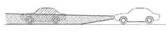
最後に、効果について説明する。本実施例によれば、車両用照明装置1は、自車両が前方車両に対して自動追従走行を行っている場合、又は自車両と前方車両との車間距離が近距離の場合に、ハイビームランプ140又はロービームランプ141が照射中であれば、照射状態をロービームランプ141が通常より下向きである照射状態に変更する。これにより、図4及び図5に示す照射状態変更前のハイビームランプ140又はロービームランプ141の照射対象位置から、図6及び図7に示す照射状態変更後のロービームランプ141の照射対象位置が自車両手前側に移動するため、通常のロービームランプ141の照射状態よりも、前方車両乗員への眩惑を軽減可能な照射状態にすることが可能となる。 Finally, the effect will be described. According to the present embodiment, the
また、自車両が前方車両に対して自動追従走行を行っている場合、又は自車両と前方車両との車間距離が近距離の場合に、図8に示すように昼間点灯ランプ142が照射中であれば、図9に示すように昼間点灯ランプ142を消灯する。これは、自車両の近距離に前方車両が存在することで、周囲からの自車両の被視認性が上がり易くなり昼間点灯の必要性が低くなるため、昼間点灯ランプ142を消灯し、自車両のバッテリ負荷を低減可能な照射状態にすることができる。 In addition, when the host vehicle is automatically following the preceding vehicle, or when the distance between the host vehicle and the preceding vehicle is a short distance, the
更に、自車両が前方車両に対して自動追従走行を行っていない場合、且つ自車両と前方車両との車間距離が近距離より大きい場合、即ち通常の照射が必要であると判断される場合には、自動で照射状態変更前の照射状態に戻ることができる。例えば、昼間時の昼間点灯ランプ142の照射中に、自車両と前方車両との車間距離が近距離になり昼間点灯ランプ142照射を消灯し、その後に車間距離が近距離より大きくなると、前方車両がいなくなり自車両による被視認性の向上が必要であると判断され、昼間点灯ランプ142の照射が再開される。 Furthermore, when the host vehicle does not automatically follow the preceding vehicle and when the distance between the host vehicle and the preceding vehicle is greater than a short distance, that is, when it is determined that normal irradiation is necessary. Can automatically return to the irradiation state before the irradiation state change. For example, during irradiation of the
尚、本発明は上述した本実施例に限定されるものではなく、本発明の主旨を逸脱しない範囲で変更を施すことが可能である。 Note that the present invention is not limited to the above-described embodiment, and modifications can be made without departing from the gist of the present invention.
(変形例1)
本実施例では、前照灯14のロービームランプ141が通常より下向きである照射状態に変更し、ロービームランプ141による照射対象位置を自車両手前側に移動させることで、前方車両乗員への眩惑を軽減する例を示したが、これに限られるものではない。前照灯14による前方車両への照射面積を減少させることで、前方車両乗員への眩惑を軽減してもよい。(Modification 1)
In the present embodiment, the
前方車両への照射面積を減少させる例として、一部分を遮光する照射が可能な前照灯14を用いて、前方車両乗員が存在する範囲を遮光した照射を行ってもよい。 As an example of reducing the irradiation area to the front vehicle, the
具体的には、一部分を遮光する照射が可能な前照灯14として、DMD(Digital Micromirror Device)装置を用いる。DMD装置とは、光源と当該光源の光を反射することで投光を行う多数の微小な鏡を有しており、当該多数の鏡の角度を静電引力によって個々に変化させることで、所望の配光を可能とするMEMS(Micro Electro Mechanical System)の一種である。 Specifically, a DMD (Digital Micromirror Device) device is used as the
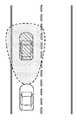
具体的には、自車両が前方車両に対して自動追従走行を行っている場合、又は自車両と前方車両との車間距離が近距離の場合に、ハイビームランプ140又はロービームランプ141が照射中であれば、前方検知センサ10による前方車両の検知に基づいて、前方車両乗員が存在する範囲を決定する。そして前照灯14は、照射制御信号に基づいて、ロービームランプ141の照射状態で、当該範囲を遮光した照射に変更する。これにより、図10に示すように、前照灯14は前方車両後端下部を照射し、前方車両後端上部、即ち前方車両乗員が存在する範囲は照射しないため、前方車両乗員への眩惑を軽減しつつ、自車両前方の視界をよくすることができる。 Specifically, the
(変形例2)
また、前照灯14の照射範囲と未照射範囲との境界であるカットラインを鮮明にすることで、前方車両乗員への眩惑を軽減してもよい。(Modification 2)
Moreover, you may reduce the glare to a front vehicle passenger | crew by clarifying the cut line which is a boundary of the irradiation range of the
具体的には、自車両が前方車両に対して自動追従走行を行っている場合、又は自車両と前方車両との車間距離が近距離の場合に、ハイビームランプ140、又はロービームランプ141が照射中であれば、前照灯14は、照射制御信号に基づいて、ロービームランプ141の照射状態で、前照灯14の光源と遮光体との距離を調整し、遮光体を光源の焦点の位置に置く。これにより、図11に示す照射状態変更前の前照灯14の照射によるぼやけたカットラインを、図12に示すように照射状態変更後は鮮明にすることができる。カットラインが鮮明になると、例えば、前方車両後端下部や路面を照射した際に、前方車両後端上部のリヤガラスが照らされにくくなるため、照射の影響を受けやすいガラスの反射などを防止し、前方車両乗員への眩惑を軽減することができる。 Specifically, the
(変形例3)
また、本実施例では、昼間点灯の必要性が低い場合に昼間点灯ランプ142を消灯することで、自車両のバッテリ負荷を低減可能な照射状態にする例を示したが、これに限られるものではない。前照灯14を減光させることによって消費電力を低くし、自車両のバッテリ負荷を低減してもよい。(Modification 3)
Further, in the present embodiment, an example has been shown in which the
前照灯14を減光させる例として、照射色の変更が可能な前照灯14を用いて、昼間点灯ランプ142の照射色を変更してもよい。具体的には、照射色の変更が可能な前照灯14としてLEDを用い、自車両が前方車両に対して自動追従走行を行っている場合、又は自車両と前方車両との車間距離が近距離の場合に、昼間点灯ランプ142が照射中であれば、前照灯14は、照射制御信号に基づき昼間点灯ランプ142の照射色を消費電力の小さい色、又は眩惑を防止する色(例えば、赤色)に変更する。 As an example of dimming the
また、照射光度が変更可能な前照灯14を用いて、前照灯14の照射光度を低下させたり、前照灯14の照射電球の数を減少させてもよい。いずれにおいても、図13に示すように、前照灯14を減光させることができ、消費電力が低くなり自車両のバッテリ負荷を低減することができる。また、消費電力の小さいLEDを、照射色又は照射光度の変更が可能な前照灯14として利用することで、自車両のバッテリ負荷の低減を更に図ることができる。 Moreover, you may reduce the irradiation light intensity of the
更に、ハイビームランプ140、又はロービームランプ141が照射中に、照射色の変更、照射光度の低下、又は照射電球の減少のうち少なくとも一つを行っても、図13に示すように、前照灯14を減光させることができ、自車両のバッテリ負荷の低減、且つ前方車両乗員への眩惑を軽減することができる。 Furthermore, as shown in FIG. 13, even if at least one of changing the irradiation color, lowering the irradiation light intensity, or reducing the irradiation bulb is performed while the
尚、以上の何れの変形例においても、本実施例と同様の効果を得ることができる。 In any of the above modifications, the same effects as in the present embodiment can be obtained.
また、本発明における前照灯14の昼間点灯ランプ142は、昼間時に照射するものであれば、専用の別付けランプ、ハイビームランプの減光、又はロービームランプのいずれかであってもよい。 Further, the
1 :車両用照明装置
10 :前方検知センサ
11 :走行支援ECU
12 :前照灯ECU
120:追従判定部
121:車間距離判定部
122:照射状態判定部
123:照射制御部
13 :レベリングモータ
14 :前照灯
140:ハイビームランプ
141:ロービームランプ
142:昼間点灯ランプ1: Vehicle lighting device 10: Front detection sensor 11: Driving assistance ECU
12: headlamp ECU
120: Tracking determination unit 121: Inter-vehicle distance determination unit 122: Irradiation state determination unit 123: Irradiation control unit 13: Leveling motor 14: Headlamp 140: High beam lamp 141: Low beam lamp 142: Daytime lighting lamp
Claims (12)
Translated fromJapanese前記自車両と該自車両前方に存在する前方車両との車間距離を検出する車間情報検出手段と、
前記自車両が前記前方車両に対して自動追従走行を行う加減速装置が追従状態にあるか否かを判定する追従判定手段と、
前記車間情報検出手段の検出車間距離が所定車間距離未満であるか否かを判定する車間距離判定手段と、
前記前照灯の照射状態を制御する照射制御手段と、
を備えた車両用照明装置において、
前記照射制御手段は、前記追従判定手段が前記加減速装置は追従状態にあると判定した場合、又は前記車間距離判定手段が検出車間距離は所定車間距離未満の近距離を示す値であると判定した場合に、前記前照灯の照射状態を変更し、
前記照射制御手段は、前記前照灯が上向きに照射するハイビーム状態、通常の下向きに照射するロービーム状態、又は昼間時に照射する昼間点灯状態のうち少なくとも一つの照射状態を変更し、
前記照射制御手段は、前記前照灯を前記ロービーム状態又は前記昼間点灯状態よりも、前記前方車両乗員への眩惑を軽減可能な照射状態、若しくは自車両のバッテリ負荷を低減可能な照射状態に変更し、
前記ロービーム状態は、車両上下方向における光軸角度が所定角度下向きの状態であり、
前記照射制御手段は、前記前照灯の光軸角度を該ロービーム状態の所定角度より下向きに傾けることを特徴とする車両用照明装置。A headlamp that illuminates the exterior of the vehicle,
A vehicle information detecting means for detecting an inter-vehicle distance to the preceding vehicle existing in the vehicle and thevehicle both forward,
And determining tracking determining means for determining whether or not the deceleration device for automatic follow-up running is in follow-up state with respect to thehost vehicle is the preceding vehicle,
An inter-vehicle distance determining means for determining whether the detected inter-vehicle distance of the inter-vehicle information detecting means is less than a predetermined inter-vehicle distance;
Irradiation control means for controlling the irradiation state of the headlamp;
In a vehicle lighting device comprising:
The irradiation control unit determines that the follow-up determining unit determines that the acceleration / deceleration device is in a following state, or the inter-vehicle distance determining unit determines that the detected inter-vehicle distance is a value indicating a short distance less than a predetermined inter-vehicle distance. If so, change the irradiation state of the headlamp,
The irradiation control means changes at least one irradiation state among a high beam state in which the headlamp irradiates upward, a normal low beam state in which the headlamp irradiates downward, or a daytime lighting state in which irradiation is performed at daytime,
The irradiation control means changes the headlamp to an irradiation state that can reduce dazzling to the vehicle occupant ahead of the low beam state or the daytime lighting state, or an irradiation state that can reduce the battery load of the host vehicle. And
The low beam state is a state in which the optical axis angle in the vehicle vertical direction is a predetermined downward angle,
The illumination device for a vehicle, wherein the irradiation control means tilts the optical axis angle of the headlamp downward from a predetermined angle in the low beam state.
前記自車両と該自車両前方に存在する前方車両との車間距離を検出する車間情報検出手段と、
前記自車両が前記前方車両に対して自動追従走行を行う加減速装置が追従状態にあるか否かを判定する追従判定手段と、
前記車間情報検出手段の検出車間距離が所定車間距離未満であるか否かを判定する車間距離判定手段と、
前記前照灯の照射状態を制御する照射制御手段と、
を備えた車両用照明装置において、
前記照射制御手段は、前記追従判定手段が前記加減速装置は追従状態にあると判定した場合、又は前記車間距離判定手段が検出車間距離は所定車間距離未満の近距離を示す値であると判定した場合に、前記前照灯の照射状態を変更し、
前記照射制御手段は、前記前照灯が上向きに照射するハイビーム状態、通常の下向きに照射するロービーム状態、又は昼間時に照射する昼間点灯状態のうち少なくとも一つの照射状態を変更し、
前記照射制御手段は、前記前照灯を前記ロービーム状態又は前記昼間点灯状態よりも、前記前方車両乗員への眩惑を軽減可能な照射状態、若しくは自車両のバッテリ負荷を低減可能な照射状態に変更し、
前記照射制御手段は、前記前照灯の照射状態が昼間点灯状態である場合に該前照灯を消灯することを特徴とする車両用照明装置。A headlamp that illuminates the exterior of the vehicle,
A vehicle information detecting means for detecting an inter-vehicle distance to the preceding vehicle existing in the vehicle and thevehicle both forward,
And determining tracking determining means for determining whether or not the deceleration device for automatic follow-up running is in follow-up state with respect to thehost vehicle is the preceding vehicle,
An inter-vehicle distance determining means for determining whether the detected inter-vehicle distance of the inter-vehicle information detecting means is less than a predetermined inter-vehicle distance;
Irradiation control means for controlling the irradiation state of the headlamp;
In a vehicle lighting device comprising:
The irradiation control unit determines that the follow-up determining unit determines that the acceleration / deceleration device is in a following state, or the inter-vehicle distance determining unit determines that the detected inter-vehicle distance is a value indicating a short distance less than a predetermined inter-vehicle distance. If so, change the irradiation state of the headlamp,
The irradiation control means changes at least one irradiation state among a high beam state in which the headlamp irradiates upward, a normal low beam state in which the headlamp irradiates downward, or a daytime lighting state in which irradiation is performed at daytime,
The irradiation control means changes the headlamp to an irradiation state that can reduce dazzling to the vehicle occupant ahead of the low beam state or the daytime lighting state, or an irradiation state that can reduce the battery load of the host vehicle. And
The illumination device for a vehicle, wherein the illumination control means turns off the headlamp when the illumination state of the headlamp is a daytime lighting state.
前記照射制御手段は、前記前方車両検知手段が前方車両を検知、且つ前記車間距離判定手段が検出車間距離は所定車間距離未満の近距離を示す値であると判定した場合に、前記前照灯の照射状態を変更することを特徴とする請求項1又は2に記載の車両用照明装置。A forward vehicle detection means for detecting the forward vehicle,
The irradiation control means, the detection of the forward vehicle preceding vehicle detectionknown means, and when the inter-vehicle distance determining means that determines that the detected inter-vehicle distance is a value indicating a short distance of less than a predetermined following distance, the headlamps The illumination device for a vehicle according to claim 1, wherein the illumination state of the lamp is changed.
Priority Applications (5)
| Application Number | Priority Date | Filing Date | Title |
|---|---|---|---|
| JP2013029269AJP6048199B2 (en) | 2012-03-22 | 2013-02-18 | Vehicle lighting device |
| PCT/JP2013/058269WO2013141353A1 (en) | 2012-03-22 | 2013-03-22 | Illumination device for vehicle |
| DE112013001700.8TDE112013001700T5 (en) | 2012-03-22 | 2013-03-22 | The vehicle lighting device |
| US14/386,251US9358920B2 (en) | 2012-03-22 | 2013-03-22 | Vehicular lighting apparatus |
| CN201380015787.2ACN104203648B (en) | 2012-03-22 | 2013-03-22 | Lighting equipment for vehicle |
Applications Claiming Priority (3)
| Application Number | Priority Date | Filing Date | Title |
|---|---|---|---|
| JP2012065711 | 2012-03-22 | ||
| JP2012065711 | 2012-03-22 | ||
| JP2013029269AJP6048199B2 (en) | 2012-03-22 | 2013-02-18 | Vehicle lighting device |
Publications (3)
| Publication Number | Publication Date |
|---|---|
| JP2013224135A JP2013224135A (en) | 2013-10-31 |
| JP2013224135A5 JP2013224135A5 (en) | 2015-09-17 |
| JP6048199B2true JP6048199B2 (en) | 2016-12-21 |
Family
ID=49222802
Family Applications (1)
| Application Number | Title | Priority Date | Filing Date |
|---|---|---|---|
| JP2013029269AExpired - Fee RelatedJP6048199B2 (en) | 2012-03-22 | 2013-02-18 | Vehicle lighting device |
Country Status (5)
| Country | Link |
|---|---|
| US (1) | US9358920B2 (en) |
| JP (1) | JP6048199B2 (en) |
| CN (1) | CN104203648B (en) |
| DE (1) | DE112013001700T5 (en) |
| WO (1) | WO2013141353A1 (en) |
Cited By (1)
| Publication number | Priority date | Publication date | Assignee | Title |
|---|---|---|---|---|
| JP2915144B2 (en) | 1993-11-18 | 1999-07-05 | リーバイ ストラウス アンド カンパニー | Automated garment finishing system |
Families Citing this family (23)
| Publication number | Priority date | Publication date | Assignee | Title |
|---|---|---|---|---|
| US9649972B2 (en)* | 2011-04-07 | 2017-05-16 | Pioneer Corporation | System for detecting surrounding conditions of moving body |
| JP6348387B2 (en)* | 2014-09-22 | 2018-06-27 | スタンレー電気株式会社 | Control method for vehicle headlamp system |
| FR3029144B1 (en)* | 2014-11-27 | 2016-12-09 | Valeo Vision | VEHICLE DRIVER ASSISTANCE SYSTEM FOR REDUCING LIGHT CONTRAST |
| CN104527509A (en)* | 2015-01-16 | 2015-04-22 | 北京北科天绘科技有限公司 | Active lighting device for vehicle |
| DE102015102178B4 (en)* | 2015-02-16 | 2023-01-26 | Dr. Ing. H.C. F. Porsche Aktiengesellschaft | lighting device |
| CN104709158A (en)* | 2015-03-30 | 2015-06-17 | 无锡市崇安区科技创业服务中心 | Self-adaptive automobile headlamp |
| JP6688008B2 (en)* | 2015-04-07 | 2020-04-28 | 株式会社小糸製作所 | Vehicle lighting |
| AT517415B1 (en)* | 2015-06-29 | 2017-04-15 | Zkw Group Gmbh | Control device for a lighting device of a motor vehicle and method for controlling such a lighting device |
| JP6368958B2 (en)* | 2016-05-12 | 2018-08-08 | 本田技研工業株式会社 | Vehicle control system, vehicle control method, and vehicle control program |
| JPWO2018051909A1 (en)* | 2016-09-15 | 2019-06-24 | 株式会社小糸製作所 | Sensor system |
| DE102016220054B4 (en) | 2016-10-14 | 2019-11-14 | Audi Ag | Method for operating display devices of motor vehicles of a motor vehicle column and system with a motor vehicle column |
| US10882449B2 (en)* | 2017-10-03 | 2021-01-05 | Ford Global Technologies, Llc | Vehicle light platoon |
| US10864854B2 (en)* | 2018-01-02 | 2020-12-15 | Getac Technology Corporation | Vehicle camera device and method for setting the same |
| US10841495B2 (en)* | 2018-01-03 | 2020-11-17 | Getac Technology Corporation | Vehicle camera device and exposure parameter setting method thereof |
| WO2019159765A1 (en)* | 2018-02-15 | 2019-08-22 | 株式会社小糸製作所 | Vehicle detection device and vehicle light system |
| CN110611772B (en)* | 2018-06-15 | 2021-06-15 | 神讯电脑(昆山)有限公司 | Image capturing device for vehicle and exposure parameter setting method thereof |
| JP7240856B2 (en)* | 2018-11-13 | 2023-03-16 | 株式会社小糸製作所 | Lamp controller and lamp assembly |
| US11198386B2 (en) | 2019-07-08 | 2021-12-14 | Lear Corporation | System and method for controlling operation of headlights in a host vehicle |
| US11485197B2 (en) | 2020-03-13 | 2022-11-01 | Lear Corporation | System and method for providing an air quality alert to an occupant of a host vehicle |
| JP7060637B2 (en) | 2020-03-16 | 2022-04-26 | 本田技研工業株式会社 | Vehicle light system |
| WO2021200803A1 (en)* | 2020-03-31 | 2021-10-07 | 株式会社小糸製作所 | Vehicle headlight and vehicle headlight system |
| US11315429B1 (en) | 2020-10-27 | 2022-04-26 | Lear Corporation | System and method for providing an alert to a driver of a host vehicle |
| CN114872613A (en)* | 2022-05-06 | 2022-08-09 | 上海海拉电子有限公司 | Car lamp control system and method and vehicle |
Family Cites Families (30)
| Publication number | Priority date | Publication date | Assignee | Title |
|---|---|---|---|---|
| US1983882A (en)* | 1934-01-10 | 1934-12-11 | Rosenfeld Myer | Automatic stopping means for vehicles |
| US2380486A (en)* | 1942-03-11 | 1945-07-31 | Jr Floyd Willis | Lighting control system |
| US2699834A (en)* | 1949-07-05 | 1955-01-18 | John C O'brien | Speed and distance responsive safety device for vehicles |
| US3749197A (en)* | 1971-05-12 | 1973-07-31 | B Deutsch | Obstacle detection system |
| JPS57167845A (en)* | 1981-04-07 | 1982-10-15 | Honda Motor Co Ltd | Vehicle throttle reaction force control system |
| FR2574725B1 (en)* | 1984-12-14 | 1987-03-20 | Cibie Projecteurs | AUTOMATIC HEADLIGHT CORRECTOR FOR VEHICLE PLATE VARIATIONS |
| JPH0667704B2 (en) | 1986-04-25 | 1994-08-31 | マツダ株式会社 | Automatic light control device for vehicle |
| JP3635166B2 (en)* | 1995-12-27 | 2005-04-06 | 株式会社デンソー | Distance measuring method and distance measuring device |
| CN1049392C (en)* | 1996-07-01 | 2000-02-16 | 张荣辉 | Automatic selection device for far light and near light for vehicles |
| JPH10175478A (en)* | 1996-12-18 | 1998-06-30 | Koito Mfg Co Ltd | Lighting fixture device for vehicle |
| DE19704427A1 (en)* | 1997-02-06 | 1998-08-13 | Bosch Gmbh Robert | Device for adjusting beam spread of automobiles headlamps |
| US6049171A (en)* | 1998-09-18 | 2000-04-11 | Gentex Corporation | Continuously variable headlamp control |
| JP2000085407A (en)* | 1998-07-17 | 2000-03-28 | Denso Corp | Vehicle-to-vehicle control device and recording medium |
| DE19942665B4 (en)* | 1998-09-07 | 2014-02-13 | Denso Corporation | FM CW radar apparatus for measuring the distance to a target and the relative velocity of the target |
| JP4076670B2 (en)* | 1999-04-09 | 2008-04-16 | 本田技研工業株式会社 | Lighting control device for automatic tracking system |
| DE10017139B4 (en) | 1999-04-07 | 2007-01-04 | Honda Giken Kogyo K.K. | Illumination control device for an automatic follow-up driving system |
| EP1130416A3 (en)* | 2000-03-02 | 2002-01-30 | Denso Corporation | Forward condition detecting apparatus for vehicles |
| JP3909647B2 (en) | 2000-12-13 | 2007-04-25 | 本田技研工業株式会社 | Auto cruise equipment |
| JP4302355B2 (en)* | 2002-03-20 | 2009-07-22 | 株式会社デンソー | Dazzle reduction device |
| US20040210369A1 (en)* | 2003-04-21 | 2004-10-21 | Denso Corporation | Automatic optical axis direction adjusting device for vehicle headlight |
| JP4286674B2 (en) | 2004-01-14 | 2009-07-01 | 本田技研工業株式会社 | Vehicle lamp control device |
| EP1593936B1 (en)* | 2004-04-30 | 2013-02-27 | Koito Manufacturing Co., Ltd | Lighting system for vehicle |
| CN2744561Y (en)* | 2004-07-16 | 2005-12-07 | 叶绍东 | Vehicle-mounted intelligent lamp gathering control device |
| JP4648816B2 (en)* | 2005-10-13 | 2011-03-09 | 川崎重工業株式会社 | Vehicle lamp device |
| JP4853160B2 (en)* | 2006-08-02 | 2012-01-11 | 株式会社デンソー | Vehicle detection device and headlamp control device |
| JP4548405B2 (en)* | 2006-10-31 | 2010-09-22 | 株式会社デンソー | Headlight swivel control device |
| JP5271571B2 (en) | 2008-03-13 | 2013-08-21 | 株式会社小糸製作所 | Vehicle headlamp device and control method thereof |
| CN201561363U (en)* | 2009-10-26 | 2010-08-25 | 上海小糸车灯有限公司 | Assembly structure of LED illumination vehicle lamp high-low lamp switching device |
| DE102009060792A1 (en)* | 2009-12-22 | 2011-06-30 | Automotive Lighting Reutlingen GmbH, 72762 | Light module for a lighting device of a motor vehicle with such a light module |
| JP2011249183A (en)* | 2010-05-28 | 2011-12-08 | Koito Mfg Co Ltd | Vehicle headlamp system, control device, and vehicle headlamp device |
- 2013
- 2013-02-18JPJP2013029269Apatent/JP6048199B2/ennot_activeExpired - Fee Related
- 2013-03-22WOPCT/JP2013/058269patent/WO2013141353A1/enactiveApplication Filing
- 2013-03-22CNCN201380015787.2Apatent/CN104203648B/ennot_activeExpired - Fee Related
- 2013-03-22USUS14/386,251patent/US9358920B2/ennot_activeExpired - Fee Related
- 2013-03-22DEDE112013001700.8Tpatent/DE112013001700T5/ennot_activeWithdrawn
Cited By (1)
| Publication number | Priority date | Publication date | Assignee | Title |
|---|---|---|---|---|
| JP2915144B2 (en) | 1993-11-18 | 1999-07-05 | リーバイ ストラウス アンド カンパニー | Automated garment finishing system |
Also Published As
| Publication number | Publication date |
|---|---|
| US20150042226A1 (en) | 2015-02-12 |
| CN104203648A (en) | 2014-12-10 |
| CN104203648B (en) | 2017-03-29 |
| JP2013224135A (en) | 2013-10-31 |
| DE112013001700T5 (en) | 2014-12-11 |
| WO2013141353A1 (en) | 2013-09-26 |
| US9358920B2 (en) | 2016-06-07 |
Similar Documents
| Publication | Publication Date | Title |
|---|---|---|
| JP6048199B2 (en) | Vehicle lighting device | |
| EP2266838B1 (en) | Vehicle headlamp apparatus | |
| JP5438410B2 (en) | Vehicle headlamp device | |
| US20080192496A1 (en) | Lamp System For Vehicle | |
| EP2269869B1 (en) | Vehicle headlamp apparatus | |
| JP5947682B2 (en) | Vehicle headlamp device | |
| JP2009214812A (en) | Vehicular headlight device and its control method | |
| JP2013224135A5 (en) | ||
| JP2011037342A (en) | Vehicular headlight system | |
| JP5222743B2 (en) | Vehicle headlamp device | |
| JP2011255826A (en) | Vehicular lighting fixture system, control device and vehicular lighting fixture thereof | |
| JP2019043260A (en) | Headlight control device | |
| EP2388163A2 (en) | Vehicle headlamp system, control device, and vehicle headlamp | |
| JP2011207349A (en) | Vehicle lamp system | |
| JP2015033954A (en) | Lighting control device for vehicle headlamp, vehicle headlamp system | |
| JP5192838B2 (en) | Auto leveling system for vehicle lamps | |
| JP7684849B2 (en) | Vehicle headlamp system | |
| CN111051132A (en) | Method for controlling at least one main headlight of a lighting unit of a vehicle, lighting unit, computer program product and computer-readable medium | |
| JP5317714B2 (en) | Vehicle headlamp device and control method thereof | |
| JP2006273092A (en) | Vehicle headlight system | |
| CN109987021B (en) | Method for adjusting motor vehicle headlights to road topography | |
| JP2010143483A (en) | Vehicle headlight device and method for controlling the same | |
| JP2018069800A (en) | Vehicular lighting fixture system | |
| JP2011162153A (en) | Auto-leveling system for vehicle lamp | |
| JP2013163417A (en) | Lighting control apparatus for vehicle headlight, and vehicle headlight system |
Legal Events
| Date | Code | Title | Description |
|---|---|---|---|
| RD01 | Notification of change of attorney | Free format text:JAPANESE INTERMEDIATE CODE: A7421 Effective date:20140829 | |
| A521 | Request for written amendment filed | Free format text:JAPANESE INTERMEDIATE CODE: A523 Effective date:20150729 | |
| A621 | Written request for application examination | Free format text:JAPANESE INTERMEDIATE CODE: A621 Effective date:20150729 | |
| A131 | Notification of reasons for refusal | Free format text:JAPANESE INTERMEDIATE CODE: A131 Effective date:20160524 | |
| A521 | Request for written amendment filed | Free format text:JAPANESE INTERMEDIATE CODE: A523 Effective date:20160719 | |
| TRDD | Decision of grant or rejection written | ||
| A01 | Written decision to grant a patent or to grant a registration (utility model) | Free format text:JAPANESE INTERMEDIATE CODE: A01 Effective date:20161025 | |
| A61 | First payment of annual fees (during grant procedure) | Free format text:JAPANESE INTERMEDIATE CODE: A61 Effective date:20161107 | |
| R151 | Written notification of patent or utility model registration | Ref document number:6048199 Country of ref document:JP Free format text:JAPANESE INTERMEDIATE CODE: R151 | |
| R250 | Receipt of annual fees | Free format text:JAPANESE INTERMEDIATE CODE: R250 | |
| R250 | Receipt of annual fees | Free format text:JAPANESE INTERMEDIATE CODE: R250 | |
| R250 | Receipt of annual fees | Free format text:JAPANESE INTERMEDIATE CODE: R250 | |
| R250 | Receipt of annual fees | Free format text:JAPANESE INTERMEDIATE CODE: R250 | |
| LAPS | Cancellation because of no payment of annual fees |