JP6046715B2 - Drip-proof direct flow connector with secure lock - Google Patents
Drip-proof direct flow connector with secure lockDownload PDFInfo
- Publication number
- JP6046715B2 JP6046715B2JP2014522097AJP2014522097AJP6046715B2JP 6046715 B2JP6046715 B2JP 6046715B2JP 2014522097 AJP2014522097 AJP 2014522097AJP 2014522097 AJP2014522097 AJP 2014522097AJP 6046715 B2JP6046715 B2JP 6046715B2
- Authority
- JP
- Japan
- Prior art keywords
- valve
- male connector
- distal end
- tubular body
- distal
- Prior art date
- Legal status (The legal status is an assumption and is not a legal conclusion. Google has not performed a legal analysis and makes no representation as to the accuracy of the status listed.)
- Active
Links
- 239000012528membraneSubstances0.000claimsdescription62
- 230000008878couplingEffects0.000claimsdescription14
- 238000010168coupling processMethods0.000claimsdescription14
- 238000005859coupling reactionMethods0.000claimsdescription14
- 239000007788liquidSubstances0.000claimsdescription7
- 230000000295complement effectEffects0.000claimsdescription6
- 238000004519manufacturing processMethods0.000claimsdescription6
- 238000007789sealingMethods0.000claimsdescription6
- 230000000149penetrating effectEffects0.000claimsdescription5
- 238000000034methodMethods0.000claimsdescription4
- 239000012530fluidSubstances0.000description15
- 238000004140cleaningMethods0.000description6
- 230000015572biosynthetic processEffects0.000description5
- 239000003814drugSubstances0.000description4
- 229940079593drugDrugs0.000description4
- 239000000463materialSubstances0.000description4
- 238000000926separation methodMethods0.000description4
- 238000013519translationMethods0.000description4
- 239000004944Liquid Silicone RubberSubstances0.000description3
- 229920001707polybutylene terephthalatePolymers0.000description3
- 229920002379silicone rubberPolymers0.000description3
- 230000006835compressionEffects0.000description2
- 238000007906compressionMethods0.000description2
- 238000009472formulationMethods0.000description2
- 239000000203mixtureSubstances0.000description2
- 230000035515penetrationEffects0.000description2
- 241000894006BacteriaSpecies0.000description1
- 230000000844anti-bacterial effectEffects0.000description1
- 230000000845anti-microbial effectEffects0.000description1
- 239000003899bactericide agentSubstances0.000description1
- 230000004888barrier functionEffects0.000description1
- 230000037237body shapeEffects0.000description1
- 230000015556catabolic processEffects0.000description1
- 238000004891communicationMethods0.000description1
- 238000012864cross contaminationMethods0.000description1
- 238000005520cutting processMethods0.000description1
- 230000006378damageEffects0.000description1
- 238000006731degradation reactionMethods0.000description1
- 230000006866deteriorationEffects0.000description1
- 230000000694effectsEffects0.000description1
- 230000005489elastic deformationEffects0.000description1
- 229920001971elastomerPolymers0.000description1
- 239000000806elastomerSubstances0.000description1
- 239000013536elastomeric materialSubstances0.000description1
- 210000003743erythrocyteAnatomy0.000description1
- 238000002347injectionMethods0.000description1
- 239000007924injectionSubstances0.000description1
- 238000003780insertionMethods0.000description1
- 230000037431insertionEffects0.000description1
- 238000005304joiningMethods0.000description1
- 238000012986modificationMethods0.000description1
- 230000004048modificationEffects0.000description1
- 244000052769pathogenSpecies0.000description1
- 239000000088plastic resinSubstances0.000description1
- -1polybutylene terephthalatePolymers0.000description1
- 229920001296polysiloxanePolymers0.000description1
- 238000002360preparation methodMethods0.000description1
- 238000004381surface treatmentMethods0.000description1
- 239000011800void materialSubstances0.000description1
Images


Classifications
- F—MECHANICAL ENGINEERING; LIGHTING; HEATING; WEAPONS; BLASTING
- F16—ENGINEERING ELEMENTS AND UNITS; GENERAL MEASURES FOR PRODUCING AND MAINTAINING EFFECTIVE FUNCTIONING OF MACHINES OR INSTALLATIONS; THERMAL INSULATION IN GENERAL
- F16L—PIPES; JOINTS OR FITTINGS FOR PIPES; SUPPORTS FOR PIPES, CABLES OR PROTECTIVE TUBING; MEANS FOR THERMAL INSULATION IN GENERAL
- F16L37/00—Couplings of the quick-acting type
- F16L37/02—Couplings of the quick-acting type in which the connection is maintained only by friction of the parts being joined
- A—HUMAN NECESSITIES
- A61—MEDICAL OR VETERINARY SCIENCE; HYGIENE
- A61M—DEVICES FOR INTRODUCING MEDIA INTO, OR ONTO, THE BODY; DEVICES FOR TRANSDUCING BODY MEDIA OR FOR TAKING MEDIA FROM THE BODY; DEVICES FOR PRODUCING OR ENDING SLEEP OR STUPOR
- A61M39/00—Tubes, tube connectors, tube couplings, valves, access sites or the like, specially adapted for medical use
- A61M39/10—Tube connectors; Tube couplings
- F—MECHANICAL ENGINEERING; LIGHTING; HEATING; WEAPONS; BLASTING
- F16—ENGINEERING ELEMENTS AND UNITS; GENERAL MEASURES FOR PRODUCING AND MAINTAINING EFFECTIVE FUNCTIONING OF MACHINES OR INSTALLATIONS; THERMAL INSULATION IN GENERAL
- F16L—PIPES; JOINTS OR FITTINGS FOR PIPES; SUPPORTS FOR PIPES, CABLES OR PROTECTIVE TUBING; MEANS FOR THERMAL INSULATION IN GENERAL
- F16L29/00—Joints with fluid cut-off means
- F16L29/005—Joints with fluid cut-off means joints with cut-off devices which can be perforated
- F—MECHANICAL ENGINEERING; LIGHTING; HEATING; WEAPONS; BLASTING
- F16—ENGINEERING ELEMENTS AND UNITS; GENERAL MEASURES FOR PRODUCING AND MAINTAINING EFFECTIVE FUNCTIONING OF MACHINES OR INSTALLATIONS; THERMAL INSULATION IN GENERAL
- F16L—PIPES; JOINTS OR FITTINGS FOR PIPES; SUPPORTS FOR PIPES, CABLES OR PROTECTIVE TUBING; MEANS FOR THERMAL INSULATION IN GENERAL
- F16L37/00—Couplings of the quick-acting type
- F16L37/28—Couplings of the quick-acting type with fluid cut-off means
- F16L37/38—Couplings of the quick-acting type with fluid cut-off means with fluid cut-off means in only one of two pipe-end fittings
- A—HUMAN NECESSITIES
- A61—MEDICAL OR VETERINARY SCIENCE; HYGIENE
- A61M—DEVICES FOR INTRODUCING MEDIA INTO, OR ONTO, THE BODY; DEVICES FOR TRANSDUCING BODY MEDIA OR FOR TAKING MEDIA FROM THE BODY; DEVICES FOR PRODUCING OR ENDING SLEEP OR STUPOR
- A61M39/00—Tubes, tube connectors, tube couplings, valves, access sites or the like, specially adapted for medical use
- A61M39/10—Tube connectors; Tube couplings
- A61M2039/1033—Swivel nut connectors, e.g. threaded connectors, bayonet-connectors
- A—HUMAN NECESSITIES
- A61—MEDICAL OR VETERINARY SCIENCE; HYGIENE
- A61M—DEVICES FOR INTRODUCING MEDIA INTO, OR ONTO, THE BODY; DEVICES FOR TRANSDUCING BODY MEDIA OR FOR TAKING MEDIA FROM THE BODY; DEVICES FOR PRODUCING OR ENDING SLEEP OR STUPOR
- A61M39/00—Tubes, tube connectors, tube couplings, valves, access sites or the like, specially adapted for medical use
- A61M39/22—Valves or arrangement of valves
- A61M39/26—Valves closing automatically on disconnecting the line and opening on reconnection thereof
- A61M2039/267—Valves closing automatically on disconnecting the line and opening on reconnection thereof having a sealing sleeve around a tubular or solid stem portion of the connector
- Y—GENERAL TAGGING OF NEW TECHNOLOGICAL DEVELOPMENTS; GENERAL TAGGING OF CROSS-SECTIONAL TECHNOLOGIES SPANNING OVER SEVERAL SECTIONS OF THE IPC; TECHNICAL SUBJECTS COVERED BY FORMER USPC CROSS-REFERENCE ART COLLECTIONS [XRACs] AND DIGESTS
- Y10—TECHNICAL SUBJECTS COVERED BY FORMER USPC
- Y10T—TECHNICAL SUBJECTS COVERED BY FORMER US CLASSIFICATION
- Y10T137/00—Fluid handling
- Y10T137/9029—With coupling
Landscapes
- Engineering & Computer Science (AREA)
- General Engineering & Computer Science (AREA)
- Health & Medical Sciences (AREA)
- Heart & Thoracic Surgery (AREA)
- Mechanical Engineering (AREA)
- Anesthesiology (AREA)
- Hematology (AREA)
- Life Sciences & Earth Sciences (AREA)
- Animal Behavior & Ethology (AREA)
- General Health & Medical Sciences (AREA)
- Public Health (AREA)
- Veterinary Medicine (AREA)
- Biomedical Technology (AREA)
- Pulmonology (AREA)
- Infusion, Injection, And Reservoir Apparatuses (AREA)
- Quick-Acting Or Multi-Walled Pipe Joints (AREA)
Description
Translated fromJapanese本発明は、特に医療用の、流体回路のためのコネクタに関する。 The present invention relates to a connector for a fluid circuit, particularly for medical use.
かかる確実なコネクタが特許文献1により知られている。このコネクタは雌型「ルアー」タイプの遠位入口コーンを備え、遠位入口コーンはそれに適合する相補形の雄型「ルアー」タイプのコネクタを有するデバイスと連結されるように設計されている。遠位入口コーンは、連結する前に病原菌または細菌を除去するために簡単にクリーニング可能な面一の表面を有する隔膜またはメンブレンによって塞がれる。この隔膜は、接続されると、接続される雄型「ルアー」タイプのコネクタにある穴の中に部分的に延びる管を保護する。連結されると、特許文献1のコネクタは、直線状の管状通路と低減されたデッドボリュームを有する。特許文献1に記載のコネクタは確実な雌型コネクタである。 Such a secure connector is known from US Pat. The connector includes a female “Lure” type distal inlet cone, which is designed to be coupled to a device having a matching complementary male “Lure” type connector. The distal entrance cone is blocked by a septum or membrane having a flush surface that can be easily cleaned to remove pathogens or bacteria prior to joining. This diaphragm, when connected, protects the tube that extends partially into the hole in the connected male “luer” type connector. When connected, the connector of Patent Document 1 has a straight tubular passage and reduced dead volume. The connector described in Patent Document 1 is a reliable female connector.
次いで、液体回路のための確実なコネクタ・セットが特許文献2で提案された。このコネクタ・セットは雄型コネクタおよび雌型コネクタを含み、それぞれが近位カプラ、遠位カプラを含む。上記コネクタの各遠位カプラは通路を画成し、近位カプラに固定的に取り付けられた連結部材が同軸に延びる管状部品と、膜体によって遠位端が閉じられた、弾性的に変形可能なほぼ管状のメンブレンとを含む。各コネクタのメンブレンは、メンブレンが連結部材の自由端を密閉して覆う施栓位置(plugging position)と、連結部材がメンブレンを貫通する連結位置(connecting position)との間で移動可能である。さらに、雄型コネクタの遠位カプラの管状部品は、連結時、雌型コネクタの遠位カプラの管状部品内に挿入されるように設計され、その挿入は、施栓位置で雄型コネクタ、雌型コネクタのそれぞれごとにメンブレンが遠位カプラの通路を密閉してブロックするようになっている。 A reliable connector set for liquid circuits was then proposed in US Pat. The connector set includes a male connector and a female connector, each including a proximal coupler and a distal coupler. Each distal coupler of the connector defines a passageway, a tubular part extending coaxially with a coupling member fixedly attached to the proximal coupler, and an elastically deformable, closed distal end by a membrane body A substantially tubular membrane. The membrane of each connector is movable between a plugging position where the membrane seals the free end of the connecting member and a connecting position where the connecting member penetrates the membrane. Furthermore, the tubular part of the distal coupler of the male connector is designed to be inserted into the tubular part of the distal coupler of the female connector when connected, and the insertion is performed at the plugging position with the male connector and female part. For each connector, a membrane seals and blocks the passage of the distal coupler.
この連結セットは、操作者によるその組み立てに必要なステップの数を低減するという利点を有する。さらに、そのセットは、特にコネクタの遠位部品のところに、メンブレンがコネクタの遠位端と面一であることから簡単にクリーニング可能な連結手段を含む。 This linked set has the advantage of reducing the number of steps required for its assembly by the operator. In addition, the set includes connecting means that can be easily cleaned, especially at the distal part of the connector, since the membrane is flush with the distal end of the connector.
さらに、特許文献3には、密封式の雄型ルアー・コネクタが記載されている。このコネクタは、コネクタと弁の間に流路を開通するために、標準的な雌型ルアー弁に固定することができる。このために、雄型コネクタは、剛性をもった雄型ルアー・コネクタを備える遠位端と近位シールが形成された近位端とを有する剛性ハウジングを含む。このハウジングの遠位端は弁座を含む。弾性付勢部材が隔室の内部に配置され、この弾性付勢部材は、雄型コネクタを通る流体流を防止するために、アクチュエータを付勢して弁座と接触させる。アクチュエータは、雌型コネクタと係合すると遠位弁を開き、次いで近位シールを開くために近位方向に動く。雄型コネクタの遠位端の外部表面上の液体を雄型の先端に吸引するために、雌型コネクタと切り離されると雄型コネクタの内部に部分的な真空が形成される。 Further, Patent Document 3 describes a sealed male luer connector. This connector can be secured to a standard female luer valve to open a flow path between the connector and the valve. To this end, the male connector includes a rigid housing having a distal end with a rigid male luer connector and a proximal end formed with a proximal seal. The distal end of the housing includes a valve seat. An elastic biasing member is disposed within the compartment, and the elastic biasing member biases the actuator to contact the valve seat to prevent fluid flow through the male connector. When the actuator engages the female connector, it opens the distal valve and then moves proximally to open the proximal seal. In order to draw liquid on the external surface of the distal end of the male connector to the male tip, a partial vacuum is created inside the male connector when disconnected from the female connector.
特許文献4については、無針貫通点コネクタが記載されている。このコネクタは、中空スパイクと、雌型ルアーと、先端とスパイクの上に延びるばね部分とを含んだ可撓性を有する弾性スパイクブーツと、スパイクブーツの一部分を覆う芯出し部材と、芯出し部材と雌型ルアーの一方の端との間に配置された拭き取り可能な弾性隔膜を有する。中空スパイクと雌型ルアーは互いに固定され、組立体を終端する。ルアーの長さおよび/またはスパイクの長さは、雄型ルアーが雌型ルアーへと押されたときに、ブーツの先端部分がスパイクの先端によって穿孔されるように、雄型ルアーが隔膜に圧力をかけ、その隔膜をスパイクに向かって押すようなものになっている。隔膜がさらに圧縮されると、その隔膜はスパイク上に広がり、その結果先端の空洞が雄型ルアー・ハブと流体連通する。この注入ポートにより生じる逆流は最小限であり、隔膜はスパイク上に拭き取り可能な二重の抗菌バリアを構成する。 About
最後に、特許文献5に、医療用コネクタが記載されている。このコネクタは、剛性ハウジングと、このハウジングの内部に配置されて少なくとも1つの側方開口を備えた剛性内部部材と、上記ハウジングの内部に配置されてその突出部が上記側方開口内に貫通するように設計された中空の可撓性部材とを含む。 Finally, Patent Document 5 describes a medical connector. The connector includes a rigid housing, a rigid internal member disposed within the housing and having at least one side opening, and a protrusion disposed within the housing and penetrating into the side opening. A hollow flexible member designed in such a manner.
これらの医療用の液体回路コネクタは、その分離時のコネクタ出口における液滴形成の恐れを制限する、またはなくすことが重要である。実際に、こういったコネクタを介して移送されるものは一般に、多少とも薬を薄めてしまう。したがってその薬は、そういった薬の調合にはあり得ることだが、むき出しの使用者または患者にとって危険である可能性がある。コネクタ出口における液滴の形成はまた、薬自体の調合時に相互汚染源になる可能性がある。 It is important that these medical liquid circuit connectors limit or eliminate the risk of droplet formation at the connector outlet upon separation. In fact, what is transported through these connectors generally dilutes the drug somewhat. Therefore, the drug can be dangerous to the exposed user or patient, as is possible with the formulation of such drugs. The formation of droplets at the connector outlet can also be a source of cross-contamination during the preparation of the drug itself.
したがって、本発明の1つの目的は、流体回路のための確実な連結を有する雄型および雌型コネクタの新規な組立体を提案することであり、そのメンブレンおよび本体は完全にクリーニング可能であると同時に、コネクタの分離時の液滴の形成を制限し、さらにはなくす。 Accordingly, one object of the present invention is to propose a novel assembly of male and female connectors with a secure connection for fluid circuits, the membrane and body of which can be completely cleaned. At the same time, it limits and even eliminates droplet formation during connector separation.
第二に、本願の他の目的は、濃厚赤血球の破壊の恐れなど、通過する流体の劣化の恐れを制限する、流体回路のためのコネクタ組立体を提案することである。 Second, another object of the present application is to propose a connector assembly for a fluid circuit that limits the risk of deterioration of the fluid passing therethrough, such as the risk of destruction of concentrated red blood cells.
この目的のために、本発明は、液体回路のための雄型コネクタを提案し、上記雄型コネクタは、
通路を画成する管状部分を含んだ遠位ハブと、
近位ハブと、
上記遠位ハブの管状部分の内部に固定的かつ同軸に延びる連結部材と、を含み、
前記連結部材は、自由端に、スリットが貫く弁厚によって遠位端が閉じられた円筒形の弾性変形可能な弁が固定された、管状体からなり、
上記管状体に取り付けられる摺動リングとを含み、
上記摺動リングが、上記弁の上記遠位端を自由にした状態で上記弁の壁を封止する非動作位置と、上記弁の上記遠位端から離れて位置し、上記弁の上記側壁の全てまたは一部分を露出する連結位置の間で移動可能である。For this purpose, the present invention proposes a male connector for a liquid circuit, the male connector comprising:
A distal hub including a tubular portion defining a passage;
A proximal hub;
A coupling member that extends fixedly and coaxially within the tubular portion of the distal hub;
The connecting member is formed of a tubular body having a free end and a cylindrical elastically deformable valve having a distal end closed by a valve thickness through which a slit penetrates.
A sliding ring attached to the tubular body,
A non-operating position in which the sliding ring seals the valve wall with the distal end of the valve free; and a position remote from the distal end of the valve; Between the connecting positions exposing all or a portion of the.
本発明の雄型コネクタの特定の好ましい非限定的な態様は以下の通りである。
上記雄型コネクタが、上記摺動リングと上記管状体の間に支持され、上記摺動リングをその静止位置に復帰させる付勢手段をさらに含む。
上記弁が、上記管状体の上記自由端を密閉して閉じる。
上記弁がさらに、上記管状体に通じる少なくとも1つの非貫通溝を呈し、上記溝が、上記スリットとほぼ平行、または上記管状体と同軸、または上記スリットの周りに延びている。
上記弁が上記管状体にオーバーモールドされている。
上記弁の上記遠位端が凹面である。
上記静止位置で、上記弁の上記遠位端の遠位表面が、上記摺動リングの上記遠位端の遠位表面と面一である。
上記弁がさらに、上記スリットのところに、上記管状体と同軸に延びる追加の径方向の肉厚部分を含む。
上記追加の肉厚部分が楕円の形状を有し、その短径が上記摺動リングの内径とほぼ等しく、その長径が上記短径より10分の数ミリメートル大きい。
上記遠位ハブが上記管状体および上記摺動リングを、その各遠位端のみを自由にした状態で覆う。
上記摺動リングがさらに、上記摺動リングと上記遠位ハブの間に延びるガスケットを含む。
上記ガスケットが、上記摺動リングの径方向の空洞に配置、または上記摺動リングにオーバーモールドされる。
上記管状体の上記遠位端が、上記弁を収容する肩を含み、その結果、上記弁および上記管状体の上記側壁の外側表面が連続的になっている。
上記管状体が、ほぼ一定の断面の内側流路を画成する。
上記遠位ハブがさらにロック手段を含む。
上記ロック手段がバヨネット・タイプである。
上記遠位ハブの上記遠位端が、上記遠位ハブと位置合わせされた芯出し壁を有する。
上記管状体が、その遠位端からその近位端に向かって上記弁の上記スリットと平行に延びるスリットを有し、2つの側方脚を画成している。
上記弁の上記スリットが、上記管状体に向かって傾斜している。Certain preferred non-limiting aspects of the male connector of the present invention are as follows.
The male connector is supported between the sliding ring and the tubular body, and further includes a biasing means for returning the sliding ring to its stationary position.
The valve seals and closes the free end of the tubular body.
The valve further exhibits at least one non-through groove leading to the tubular body, the groove extending substantially parallel to the slit, coaxial with the tubular body, or around the slit.
The valve is overmolded on the tubular body.
The distal end of the valve is concave.
In the rest position, the distal surface of the distal end of the valve is flush with the distal surface of the distal end of the sliding ring.
The valve further includes an additional radially thickened portion extending coaxially with the tubular body at the slit.
The additional thick part has an elliptical shape, the minor axis is substantially equal to the inner diameter of the sliding ring, and the major axis is a few tenths of a millimeter larger than the minor axis.
The distal hub covers the tubular body and the sliding ring, leaving only their distal ends free.
The sliding ring further includes a gasket extending between the sliding ring and the distal hub.
The gasket is disposed in a radial cavity of the sliding ring or overmolded on the sliding ring.
The distal end of the tubular body includes a shoulder that houses the valve, so that the outer surface of the valve and the side wall of the tubular body are continuous.
The tubular body defines an inner channel with a substantially constant cross section.
The distal hub further includes locking means.
The locking means is a bayonet type.
The distal end of the distal hub has a centering wall aligned with the distal hub.
The tubular body has a slit extending parallel to the slit of the valve from its distal end toward its proximal end and defines two lateral legs.
The slit of the valve is inclined toward the tubular body.
第2の態様によると、本発明は、本発明による雄型コネクタのための製造方法を提案し、上記製造方法は、
管状体を提供するステップと、
上記管状体の遠位端に上記弁を固定するステップと、
上記近位ハブに上記管状体を固定するステップと、
上記管状体の上記遠位端に上記摺動リングを搭載するステップと、
上記管状体に上記遠位ハブを固定するステップとを含む。According to a second aspect, the present invention proposes a manufacturing method for a male connector according to the present invention, the manufacturing method comprising:
Providing a tubular body;
Securing the valve to the distal end of the tubular body;
Securing the tubular body to the proximal hub;
Mounting the sliding ring on the distal end of the tubular body;
Securing the distal hub to the tubular body.
本発明による管状体の特定の好ましい非限定的な態様は以下の通りである。
上記方法が、上記管状体の上記遠位端に上記弁を固定した後に、上記弁に上記スリットが形成されるステップをさらに含む。
上記弁が、上記管状体にオーバーモールドすることによって取り付けられる。Certain preferred non-limiting embodiments of the tubular body according to the present invention are as follows.
The method further includes the step of forming the slit in the valve after securing the valve to the distal end of the tubular body.
The valve is attached by overmolding the tubular body.
第3の態様によると、本発明は、本発明による雄型コネクタと雌型コネクタとを含んだ液体回路のための連結組立体を提案し、上記雌型コネクタは、
遠位ハブと、
近位ハブを含み、
上記遠位ハブが、上記近位ハブに固定的に搭載された連結部材が同軸に延びる管状部分と、上記メンブレンが上記連結部材の自由端を密閉して覆う施栓位置と、上記連結部材が上記メンブレンおよび上記弁を貫通する連結位置との間で移動可能であり、スリットが貫通する隔膜によって遠位端が弾性的に閉じられ、変形可能な円筒形のメンブレンを含む。According to a third aspect, the present invention proposes a coupling assembly for a liquid circuit including a male connector and a female connector according to the present invention, the female connector comprising:
A distal hub;
Including a proximal hub,
The distal hub has a tubular portion in which a connecting member fixedly mounted on the proximal hub extends coaxially, a plugging position where the membrane seals and covers a free end of the connecting member, and the connecting member includes the connecting member It includes a cylindrical membrane that is movable between a membrane and a connecting position that penetrates the valve, is elastically closed at its distal end by a diaphragm through which a slit passes, and is deformable.
上記組立体の特定の好ましい非限定的な態様は以下の通りである。
上記雄型コネクタを上記雌型コネクタと連結しているときは、上記弁が上記雌型コネクタの上記遠位ハブの上記遠位端を貫通できるように、上記雄型コネクタの上記弁の形状および寸法が上記メンブレンの形状および寸法とほぼ等しい。
上記メンブレンの上記遠位端が凸形の表面を有し、上記弁の上記遠位端が凹形の表面を有し、上記弁の上記遠位端の表面の凹面が、上記メンブレンの上記遠位端の表面の凸形に対応する。
上記雌型コネクタおよび上記雄型コネクタがそれぞれ、相補形のバヨネット・ロック手段を含む。
上記雄型コネクタを上記雌型コネクタと連結しているときは、上記雌型コネクタの上記遠位端が上記雄型コネクタの上記遠位ハブの上記遠位端を貫通できるように、上記雌型コネクタの上記遠位ハブの寸法および形状が上記摺動リングの寸法および形状とほぼ同一になっている。
上記雄型コネクタの上記管状体が、その遠位端からその近位端に向かって上記弁の上記スリットと平行に延びるスリットを有して2つの側方脚を画成し、上記雌型コネクタの上記連結部材が上記雄型コネクタの上記弁の上記スリットへ貫通している間に、上記雄型コネクタの上記側方脚が弾性変形する。Certain preferred non-limiting aspects of the assembly are as follows.
When the male connector is coupled to the female connector, the valve shape of the male connector and the valve so that the valve can penetrate the distal end of the distal hub of the female connector; The dimensions are approximately equal to the shape and dimensions of the membrane.
The distal end of the membrane has a convex surface, the distal end of the valve has a concave surface, and the concave surface of the surface of the distal end of the valve is the far surface of the membrane. Corresponds to the convex shape of the top end surface.
The female connector and the male connector each include complementary bayonet locking means.
When the male connector is coupled to the female connector, the female end is configured so that the distal end of the female connector can penetrate the distal end of the distal hub of the male connector. The size and shape of the distal hub of the connector is approximately the same as the size and shape of the sliding ring.
The tubular body of the male connector defines two lateral legs having a slit extending parallel to the slit of the valve from its distal end toward its proximal end; While the connecting member of the male connector passes through the slit of the valve of the male connector, the side leg of the male connector is elastically deformed.
第4の態様によると、本発明は、本発明によるコネクタ組立体の使用法を提案し、この組立体の使用法は、
上記弁(40)が上記メンブレン(130)と接触するように、上記雌型コネクタ(100)の上記遠位端(120)を上記雄型コネクタ(1)の上記遠位端(10)に対して配置するステップと、
前記弁(40)が前記雌型コネクタ(100)の前記遠位ハブ(140)の前記遠位端に貫通し、前記雌型コネクタ(100)の前記連結部材(124)が前記メンブレン(130)と前記弁(40)の両方を通過するまで、前記雄型コネクタ(1)の前記遠位ハブ(10)が前記摺動リング(50)を前記雄型コネクタ(1)の前記近位ハブに向かって前記雌型コネクタ(100)を前記雄型コネクタ(1)に向かって押すことによって、前記雌型コネクタ(100)の前記遠位ハブ(140)を前記雄型コネクタ(1)の前記遠位ハブ(10)の中に挿入するステップと、
上記組立体をロックするステップとを含む。According to a fourth aspect, the present invention proposes the use of a connector assembly according to the invention, the use of this assembly comprising:
The distal end (120) of the female connector (100) is moved relative to the distal end (10) of the male connector (1) such that the valve (40) contacts the membrane (130). And placing step,
The valve (40) penetrates the distal end of the distal hub (140) of the female connector (100), and the connecting member (124) of the female connector (100) is connected to the membrane (130). And the distal hub (10) of the male connector (1) moves the sliding ring (50) to the proximal hub of the male connector (1) until it passes through both the valve and the valve (40). By pushing the female connector (100) toward the male connector (1), the distal hub (140) of the female connector (100) is moved toward the far end of the male connector (1). Inserting into the position hub (10);
Locking the assembly.
本発明のその他の特徴、目的および利点は、非限定的な例として示されている添付の図面を参照して、以下の詳細な説明を読むとより明らかになるであろう。 Other features, objects and advantages of the present invention will become more apparent when the following detailed description is read with reference to the accompanying drawings, which are shown by way of non-limiting examples.
図1および2を参照して、まず、本発明による雌型コネクタ100について説明する。 First, a
雌型コネクタ100は、近位ハブ120と、弾性的に変形可能なほぼ管状のメンブレン130と、近位ハブ120に取り付けられる遠位ハブ140を備える。
近位ハブ120は全体的に管状の形状を有し、近位端を備える。この近位端はこの場合、雌型「ルアー・ロック」タイプの連結可能な入口121を含む。一変形形態として、連結可能な入口121は雄型「ルアー・ロック」タイプのものである。この入口は遠位方向に中空体122へと延びる。
近位ハブ120の中空体122は遠位方向で円形のフランジ123によって終端され、フランジ123には同軸方向の先端に中空連結管124が形成され、中空連結管124は近位ハブ120から遠位方向に突出して延びる。中空管124は自由遠位端125で終端し、連結部材を構成する。 The
次に、コネクタ100のメンブレン130について詳細に説明する。 Next, the
このメンブレン130は遠位端132を有し、弾性手段131を備える。 The
この場合、弾性手段131は、遠位端132まで延びる例えば螺旋状の圧縮ばねタイプなどのばね131である。弾性手段131は、近位ハブ120に支持され、メンブレン130がその静止(非動作)位置に入るようにメンブレン130の遠位端132を押すよう設計される。メンブレン130はその静止位置で通路141の遠位端を塞ぐ。 In this case, the
メンブレン130の遠位端132は全体的に凸形の遠位表面を有する隔膜であり、その遠位表面を連結管124と同軸のスリットが貫く。 The
こうして雌型コネクション100は遠位ハブ140の管状部分に覆われた(encapsulated)メンブレン130を備え、その結果操作者がアクセス可能なのはスリットが貫通する遠位表面のみとなる。これにより、静止位置において、遠位ハブ140の管状部分の壁によって実現するメンブレン130(特にその遠位端132)の径方向のクランプ固定も可能になり、これでより優れた封止および逆圧に対する耐性が得られる。 Thus, the
遠位ハブ140は、その外周に(好ましくは近位部分に)ロック手段150を備える。この場合、ロック手段は雌型で、バヨネット・タイプのものであり、これと相補形のバヨネット・ロック手段の雄型の突起と協働するように設計された溝を備えるスカート151を含む。図1および2に示されている実施形態では、遠位ハブ140の遠位端152が、スカート151によって取り囲まれ、雌型「ルアー・ロック」タイプの連結可能な入口を構成するようにねじ切りされている。この目的のために、遠位端面151が径方向からアクセス可能になるように、スカート151の遠位部分は縮めてずらされている。こうして、雄型バヨネット・ロック手段の突起または相補形の雄型「ルアー・ロック」ロック手段に連結できる雌型ロック手段が得られる。 The
こういったロック手段150について、後で詳細に説明する。 Such locking means 150 will be described in detail later.
コネクタ100と類似したコネクタの詳細な説明が前述の特許文献2に提供されている。この文献をその目的のために参照することができる。 A detailed description of a connector similar to
次に、図3〜8Bを参照して、本発明による雄型コネクタ1について説明する。 Next, the male connector 1 according to the present invention will be described with reference to FIGS.
雄型コネクタ1は、通路を画成する管状部分を備える遠位ハブ10と、近位ハブ20と、連結部材30を含む。 The male connector 1 includes a
連結部材30は、遠位ハブ10の通路11内へその管状部分と同軸に延びる。この連結部材30は、全体的に円筒形の形状をした内部流路31を形成する全体的に管状の本体形状を有し、遠位端32に弁40を有する。 The connecting
管状体30は、弁40が遠位ハブ10の遠位端11と隣接するように、遠位ハブ10の中に挿入される。
管状体30はさらに、遠位ハブの近位端12と係合するように設計された径方向の突出部分33を含む。例えば、突出部分33は、管状体の軸に対して横向きに広がるディスク形状を有し、その外径は遠位ハブ10の内径ほぼと等しい。このディスクはさらに、遠位ハブ10の内面に作られた相補形の形状の溝13と協働するように設計された、例えば環状であってもよい径方向の突出部などのスナップイン手段33aを有する。上記ディスクはまた、より大きな直径をもつ鍔部33bによって広がり、鍔部33bは遠位ハブ10のためのストッパとして働く。したがって、管状体30が遠位ハブ10の中に挿入されると、遠位ハブ10の近位端12が、ストッパとして働く鍔部33bに当てて載置され、環状の突出部分33aと係合し、その結果、遠位ハブ10の管状体30に対する平行移動がブロックされる。
最後に、管状体30は、その近位部分が、径方向の突出部分33を超えて、近位ハブ20を保持するためのゾーン34へと延びる。保持ゾーン34は、内面に少なくとも1つの連結部材34aを有する円筒形の本体を含む。保持ゾーン34は円筒形であると好ましく、このとき連結部材34aは環状に突出する形になる。このようにして、雄型コネクタ1の近位ハブ20の偶発的な解放を回避するために、近位ハブ20は管状体30に対する平行移動が固定されるが、その管状体30の周りの回転は自由となる。 Finally, the
管状体30の弁40は、全体的に円筒形状の弾性的に変形可能なメンブレンであり、遠位端41が膜で閉じられる。弁40の外径はメンブレン130の外径以下であり、メンブレン130の外径とほぼ等しいと好ましい。 The
スリット42が上記の膜厚を貫いて延び、管状体30に通じる。管状体の遠位端32とスリット42は、内部流路31に延びる内部スペース43によって分離することができる。 A
スリット42は、特にその製造方法に応じて、直線状であっても、管状体30の方向に傾斜していてもよい。 The
例えば、弁40はエラストマー材料でできており、これにより、スリット42の存在にかかわらず管状体30を密閉して閉じることが可能になる。典型的には、弁40はLSR(Liquid Silicone Rubber、液状シリコーンゴム)で製造できる一方、管状体30はPBT(ポリブチレンテレフタレート)プラスチック樹脂などのプラスチック材料でできている。この場合、それを管状体30にオーバーモールドすることができる。この事例では、弁40と管状体30の間の連結を改善するために、管状体30の遠位端は特に、その遠位端を貫通する1つまたは複数の径方向の開口36を有することができる。さらに、管状体30に対して正確に位置出しするため、スリット42は、弁40を管状体30に固定した後に例えばメスなどによって膜厚を切り開くことによって作られると好ましい。 For example, the
連結部材の外側表面に不連続部を作ることなく弁30を収容するために、弁40が固定される管状体30の遠位端32は、管状体30の壁を収縮させることによって形成された環状の肩32aを有することが好ましい。その場合、弁40は、弁40の外側壁46と管状体30が全体的に滑らかな連続表面を形成するような厚さで、この肩32aにオーバーモールド(または固定)される。 In order to accommodate the
一実施形態によると、弁40はさらに、管状体30に通じる、管状体30と同軸の、少なくとも1つの非貫通の溝44を含む。 According to one embodiment, the
溝44は、スリット42に対して二重の効果を有する。 The
以下の説明で分かるように、スリット42は、その遠位端41から物体を導入することによって開く間、溝44があることでより簡単に開くことができるようになり、溝44によって作り出される空きスペースのおかげでスリット42の縁部は拘束されることがない。 As will be seen in the following description, the
さらに、スリット42が閉じると(したがってスリット42を貫通する連結管124などの物体がないとき)、管状体30からの流体の移動があった場合に、その流体は溝44に入り、スリット42の縁部に互いに押し付けようとする圧力を加える。したがってスリット42は閉じたままであり、流体の漏れを防止し、こうしてコネクタ1の封止性が向上する。 Further, when the
溝44は、例えば環状の形状のものなどにすることができ、スリットの周囲かつスリットから一定の距離のところで、管状体30の軸に対して横向きに延びる。一変形形態として、弁40は、スリット42の両側に、スリット42と平行に延びる2本のほぼ直線状の溝44を含む。この実施形態は、より効果的な圧力をスリット42に加えるという利点を有し、したがって逆圧に対するその耐性を改善するという利点を有する。別の変形形態によると、溝44は湾曲し、スリットの両側にある。 The
最後に、一実施形態によると、弁40の遠位端41は凹形の表面である。雌型コネクタ100のメンブレン130の遠位端の表面が凸形の形状であり、これにより、弁40の遠位端がメンブレン130の表面に完全に適合することが可能になり、こうして、コネクタ1と100が互いに連結されると流体の漏れを制限することが可能になる。弁40の遠位端41の凹面は、メンブレン130の遠位端の凸形と合致していると好ましい。 Finally, according to one embodiment, the
一変形形態として、雌型コネクタ100のメンブレン130の遠位端の表面は凹形の形状のものであり、このとき、弁40の遠位端41は、それと整合する凸形を有する凸形の表面である。 As a variant, the surface of the distal end of the
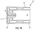
雄型コネクタ1はさらに、非動作状態のいわゆる静止位置と連結位置の間で移動可能な、管状体30に取り付けられた摺動リング50を含む。 The male connector 1 further includes a sliding
静止位置では、リング50は、弁40の側壁46を封止し、その遠位端41のみを自由状態にしておく。弁40の遠位端41は、縁を最小限にし、コネクタ1のクリーニングを容易にするために、リング50の遠位端51の表面と面一になっていると好ましい。この位置は特に図3、4、8A、8Bおよび10に示されている。 In the rest position, the
連結位置では(特に図11〜13に示されている)、リング50は、弁40の遠位端41から一定の距離に配置され、弁40の全てまたは一部分を露出する。 In the coupled position (particularly shown in FIGS. 11-13), the
リング50の内径は、管状体30および弁40の外径とほぼ等しいことが好ましい。 The inner diameter of the
弁40はさらに、その遠位端41に、スリット42に隣接して径方向に延びるわずかな肉厚部分45(弁40の全厚の5%程度)を有してもよい。これにより、静止位置では、リング50は、その内径が肉厚部分45における弁40の外径よりもわずかに小さく、中心に向かう径方向の力を弁40およびスリット42にかける。その結果、静止状態でリング50はさらに、弁40の逆圧に対する耐性を高める。 The
さらに、肉厚部分45により、リング50と弁40の間の流体の通過を防止することが可能になる。 Furthermore, the
図に示されている実施形態では、肉厚部分45は、圧力がスリット42の片側のみにかけられるようにそのスリット42の片側のみに存在しており、これによって逆圧に対するその耐性が改善される。例えば、肉厚部分は、楕円の形状を有することができ、その短径(スリット42の両端)はリング50の内径とほぼ等しく、長径(スリット42の縁部)は短径より10分の数ミリメートル大きい。 In the embodiment shown in the figure, the thickened
摺動リング50と遠位ハブ10の間の流体の通過を制限するために、摺動リング50の外径は遠位ハブ10の内径とほぼ等しいと好ましい。必要なら、コネクタ1の封止をさらに改善し、殺菌剤などの製剤の導入を回避するために、リング50の外側表面はさらに、Oリング・ガスケット53を受けるように設計された環状の溝52を含むことができる。 In order to limit the passage of fluid between the sliding
Oリング53は、例えばLSRシリコーンなどのエラストマー材料で製造することができる。 The O-
一変形形態として、Oリング53は、環状溝52の有無にかかわらず、リング50に直接オーバーモールドされる。 As a variant, the O-
弁40と接触するリング50の内側表面は滑らかであると好ましく、このために、管状体30に沿ったリング50の動きを容易にするために表面処理を施してもよい。例えば、リング50の内側の面をシリコーン処理してもよい。 The inner surface of the
リング50の摺動はさらに、弁40および管状体30の外側表面が連続的で一定の直径のものであることによって改善される。 The sliding of the
リング50は、例えばPBTタイプのプラスチック材料で製造することができる。 The
雄型コネクタ1はさらに、摺動リング50をその静止位置に復帰させるように設計された付勢手段60を含む。 The male connector 1 further includes biasing means 60 designed to return the sliding
図に示されている実施形態では、付勢手段60は、摺動リング50の近位面54と管状体30の径方向の空洞33の遠位面の間に延びる、管状体30と同軸の弾性ばねである。これにより、摺動リング50がその連結位置に向かって動かされると、ばね60は、その反対の方向のコネクタ1の遠位端の方へと押そうとする付勢力を、そのリング50に対してかける。 In the illustrated embodiment, the biasing means 60 is coaxial with the
ただし、この付勢手段60の実施形態は限定的なものではない。これはまた、圧縮時に動作するベローズなどからなっていてもよい。 However, the embodiment of the biasing means 60 is not limited. It may also consist of a bellows that operates during compression.
復帰手段60が静止状態にあるときに、摺動リング50もまたその静止位置にあると好ましい。 When the return means 60 is stationary, the sliding
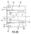
特に図6に示されている実施形態によると、管状体30にさらに、その遠位端からその近位端の方へスリットを入れることができる。管状体30におけるスリット35aは、例えば弁40と接触している遠位部分において、管状体30の一部分のみを覆って延び、その管状体の遠位部分に径方向の一定の弾性をもたらすと好ましい。 In particular, according to the embodiment shown in FIG. 6, the
管状体30のスリット35aは、弁40のスリット42とほぼ平行であることが好ましい。 The slit 35 a of the
さらに、好ましい一実施形態によると、スリット35aは、そのスリット35aを形成する縁部が互いに隔てられるように、管状体30に形成されている。したがって管状体30の遠位部分は、図6に示されているように、スリット35aによって分離された2つの側方脚35bからなる。こうして、弁40がオーバーモールドによって管状体30の遠位部分に固定される場合には、そのオーバーモールドは、弁40の側壁46がスリット35aを埋めて、管状体30の脚35bを覆うように行われる。 Further, according to a preferred embodiment, the slit 35a is formed in the
摺動リング50の静止位置において、弁40のスリット42の封止をさらに改善するために、管状体30の側方脚35bがリング50によって管状体30の内部流路31の方へ径方向に拘束されると有利である。これにより、弁40の逆圧に対する耐性が改善される。 In order to further improve the sealing of the
さらに、スリット35aによって作り出されるスペースにより、管状体30の遠位部分によって制限されずに、任意の幅のスリット42の生成が可能になる。 Furthermore, the space created by the slit 35a allows the creation of
雄型コネクタ1におけるこのスリット35aの機能についてはこの後の説明で分かる。 The function of the slit 35a in the male connector 1 will be understood from the following description.
遠位ハブ10は管状体30と摺動リング50に固定され、その固定は、遠位ハブ10の遠位端12が径方向の肉厚部分33に接して静止し、その肉厚部分33と係合し、遠位ハブ10が摺動リング50および弁40を覆っている。したがって、遠位ハブ10は、管状体30に対する平行移動(translation)が固定される。ただし、このスナップイン手段33aの実施形態によると、例えば突出部分33および溝13が環状であり、管状体30と同軸に延びる場合、遠位ハブは、管状体30の周りの回転は許容されている。 The
図10、12および13に示されている実施形態では、遠位ハブ10はさらに、その遠位端11に、少なくとも1つの湾曲した芯出し壁14を含み、芯出し壁14は、ハブ10の遠位端の外側表面から延びる。かかる芯出し壁14により、雄型コネクタ1とそれに対応する雌型コネクタを連結しながら、それらのコネクタの同一軸に対する位置合わせが容易になる。これにより、それらのコネクタの正確な動作が保証され、その劣化が回避される。 In the embodiment shown in FIGS. 10, 12 and 13, the
遠位ハブ10は、面一の弁40の遠位表面41と摺動リング50の遠位表面51のクリーニングを容易にするために、2つのノッチ15によって径方向に分離された少なくとも2つの向かい合う芯出し壁14を含むことが好ましい。 The
芯出し壁14の内部面はさらに、雌型コネクタ100の案内をさらに改善するために、径方向内向きに延びる傾斜した突出部14aを含むことができる。 The inner surface of the centering
遠位ハブ10の遠位端11はさらに、好ましくはバヨネット・タイプのロック手段16を含む。この場合、ロック手段はバヨネット・システムの2つの雄型突起16であり、各突起は芯出し壁14の外側表面から延びる。 The
一変形形態として(図示せず)、遠位ハブ10の遠位端11は、雌型バヨネット・ロック手段を有する遠位スカートを含む。 As a variant (not shown), the
このタイプのロック手段16は、従来のねじタイプのロック手段と比較して、そのロック手段へのアクセスが容易になるように全体的に滑らかな表面を有するという利点を有し、したがってそれらをクリーニングし易い。さらに、そういったロック手段により、雄型コネクタ1と対応する雌型コネクタ100との簡易で確実なロックが実現される。 This type of locking means 16 has the advantage of having a generally smooth surface compared to conventional screw-type locking means so as to facilitate access to the locking means, thus cleaning them. Easy to do. Furthermore, such a locking means realizes simple and reliable locking between the male connector 1 and the corresponding
さらに、遠位ハブ10は、雄型コネクタ1を把持する手段15をさらに含む。この場合その手段は数が2つであり、遠位ハブ10の両側に径方向に延びる2つの空洞の形をとる。これらの把持手段15により、雄型コネクタ1を雌型コネクタ100と連結するときに、雄型コネクタ1をしっかりと把持することが可能になる。 Furthermore, the
近位ハブ20に関しては、その近位端22に、雌型「ルアー・ロック」タイプの従来の連結可能な入口23を備え、入口23は、図に示されていない態様で、雄型の「ルアー」、「スリップ」(平滑状)または「ロック」(ロック付)タイプの連結端を有するシリンジ(または他の任意の適当な医療機器)に組み付けることができる。この連結可能な入口23は、最大3barまでの圧力に対して封止されることが好ましい。このために、例えば、管状体30の近位部分34の外径は、近位ハブ20の連結可能な入口23における内径よりもわずかに大きい。 With respect to the
さらに、近位ハブ20は、管状体30と同軸の円筒形の保持部材24を含み、保持部材24は、それに対応する、管状体30の保持ゾーンに該当する保持部材34aと協働するように設計される。これにより、近位ハブ20は、管状体30に対する平行移動が固定される一方、その軸の周りの回転は許容される。したがって、雄型コネクタ1の任意の意図的でない回転運動は(例えば、雄型コネクタ1と雌型コネクタ100を、そのバヨネット・ロック手段16を切り離すために回転させることによって切り離している最中など)、管状体30に対する遠位ハブ20の自在な回転によって相殺され、こうして、雄型コネクタ1とシリンジの偶発的な切り離しが回避される。 Further, the
次に、本発明による雄型コネクタ1およびそれに対応する雌型コネクタを含んだコネクタ組立体の使用方法について説明する。 Next, a method for using the male connector 1 according to the present invention and the connector assembly including the corresponding female connector will be described.
この場合、雌型コネクタは、添付の図1および2を参照して上記で説明した、欧州特許第2011/05231号に詳述されているコネクタ100に該当する。ただしこれは限定的なものではない。 In this case, the female connector corresponds to the
第1のステップでは、2つのコネクタ1および100の遠位端がクリーニングされる。各コネクタ1、100の遠位表面が滑らかになるように、雄型コネクタ1の弁40と雌型コネクタ100のメンブレン130がそれぞれ遠位ハブの遠位端と面一になっているので、このクリーニングはそれだけ簡単である。必要なら、従来のねじをバヨネット・ロック手段16、150と置き換えることによってもやはり、雌型コネクタ100のスカート151のオフセットのおかげでこのクリーニングが容易になる。これより、雄型コネクタのロック手段上の従来のねじ山がなくなるだけでなく、コネクタ100の遠位端152のねじ山への簡単なアクセスも可能になる。 In the first step, the distal ends of the two
上記のクリーニングが行われると、操作者は、雄型コネクタおよび雌型コネクタ100のそれぞれの遠位端を接触させる。このために、操作者は、メンブレン130の凸形の表面に弁40の凹形の表面を当てる。このとき、図9および10に示されているように、摺動リング50の遠位端51に接した遠位ハブ140の遠位端により組立体が連結される。 When the above cleaning is performed, the operator brings the distal ends of the
2つのコネクタ、雌型100および雄型1の遠位ハブ140および10は、構造的に類似していることが分かるであろう(当然ながらそれら各ロック手段は別である)。つまり、雄型コネクタ1と雌型コネクタ100の結合/結合解除が1つの軸方向の動きだけで行われるように、メンブレン130および弁40は実際に、それらの遠位ハブ140、10の遠位端と面一になっている。実際に、雌型コネクタ100と雄型コネクタ1を互いに押し付け始める前に、雌型コネクタ100および雄型コネクタ1の遠位ハブ140、10を取り付ける必要はなく、遠位ハブ140、240の構造のおかげでその2つの操作が同時に行われる。 It will be appreciated that the two connectors, female 100 and male 1,
この場合、操作者は、雄型コネクタと雌型コネクタの各ロック手段を互いに向かい合わせて配置し、次いでそれらをロックする。示されている例示的な実施形態では、操作者は、例えば雌型コネクタ100の対応する溝150に向けて雄型コネクタ1の突起16を配置し、雄型コネクタ1の遠位ハブ10の芯出し手段14によって支持されたその雄型コネクタ1を雌型コネクタ100の方へ押すことによって、コネクタ100、1を互いに摺動させる。 In this case, the operator arranges the locking means of the male connector and the female connector so as to face each other, and then locks them. In the exemplary embodiment shown, the operator places the
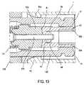
この操作中、雄型コネクタ1の弁40が雌型コネクタ100のメンブレン130の遠位端を押すと同時に、雌型コネクタ100の遠位ハブ140が雄型コネクタの摺動リング50を押す。その結果、雄型コネクタ1の弁40および管状体30の一部分が雌型コネクタ100の遠位ハブ140の中に貫通すると同時に、雄型コネクタ100の遠位ハブ140の遠位端が雄型コネクタ1の遠位ハブ10の遠位端11の中に貫通する。 During this operation, the
この目的のために、メンブレン30がその連結位置の方へ下がるように、弁40が弾性手段131を圧縮させ、それによって中空管124の遠位端125がスリット133を貫いて通過させられ、上記隔膜はメンブレン130の遠位端に位置する。それと同時に、雌型コネクタ100の遠位ハブ140の遠位端が摺動リング50に接して静止し、復帰手段60を圧縮させ、こうして摺動リング50をその連結位置の方へ動かす。一方で、弁40および管状体30は、雄型コネクタ1の遠位ハブ10および近位ハブ20に対して動かない。 For this purpose, the
さらに、弁40の開放は、特にその弁40が固定された管状体30の遠位部分によって軸方向の剛性がもたらされることから、雌型コネクタ100の中空管124の遠位端125が膜を貫通しない限り行われない。 In addition, the opening of the
好ましい一実施形態によると、弁40の材料および厚さは、弁40がメンブレン130を押すときに、弁40が開いたり、管状体30に向かって撓んだりしないように十分に丈夫であるように選択される。この目的は、実際には、弁40が、雌型コネクタ100のメンブレン130をその連結位置に向かって下がらせるために、操作者によって把持手段14にかけられた推力を、雌型コネクタ100のメンブレン130に伝達することであり、その際連結管124の遠位端125がメンブレン130を通過する。 According to one preferred embodiment, the material and thickness of the
弁40の撓みに対するこの耐性はまた、弁40が管状体30の遠位部分に固定されることによって、軸方向に強化される。さらに、必要であれば、側方脚35bの存在がさらに、弁40の軸方向の剛性を強化する。 This resistance to deflection of the
管124の遠位端125がメンブレン130の遠位端の膜厚を通過すると、この管124の遠位端125は、雄型コネクタ1の弁40と支持接触する。操作者が雄型コネクタ1と雌コネクタ100を互いに押し続けると、管124の遠位端125が弁40の遠位端41を押し、最後に弁40のスリット42内に貫通する。実際に、この段階で、上記弾性手段はすでに強く圧縮され、スリット42の縁部の力のよりも大きい復帰力をかけ、その結果そのスリット42の縁部は降伏し、広がって連結管124の通過を可能にする。 As the
上記圧力は、雌型コネクタ100の管124の遠位端125が雄型コネクタ1の管状体30と流体接続するまで継続する。この時点で、雄型コネクタ1と雌型コネクタ100の間で連結および流体通過が実現する。 The pressure continues until the
ここで、雌型コネクタ100の連結管124の遠位端125は、必ずしも管状体30の遠位端の中に貫通しなくてもよい。実際に、図12および13に示されているように、遠位端125が管状体30の遠位端と隣接すればよい。 Here, the
次いで、操作者は、雄型コネクタの突起16を雌型コネクタ100の対応する溝150の限界に位置させて、コネクタ100、1の組立体をロックするために、コネクタを互いに回転させる。 The operator then positions the
弁40のスリット42への雌型コネクタ100の連結管124の遠位端125の貫通を容易にするために、管状体30はそのスリット35aに沿って開く。側方脚35bが存在することによって、この開きが容易になる。側方脚35bは、管状体30の遠位端に可撓性を(スリット35aの平面に対して垂直な方向に)もたらし、その管状体30の遠位端の、弁40に対する連結管124の影響下での弾性変形を可能にする。これにより、連結管124の遠位端125の通過を可能にするためにスリット42の縁部が最終的に開くと、弁40は部分的に撓み、管状体30の側方脚35bは互いに遠ざかるように弾性的に変形し、こうして、遠位端125の通過を容易にするために、側方脚35bにより弁40にかかる軸方向の抗力が低減される。 To facilitate the penetration of the
この連結段階で、摺動リング50はその連結位置の近くにあり、その結果、摺動リング50がこの開口を妨げないことが分かるであろう。一方、静止位置では、摺動リング50は管状体30のスリット35aを閉じようとする。 It will be appreciated that at this coupling stage, the sliding
溝44があれば、それによってスリット42の縁部を広げることが容易になる。 The presence of the
切り離し時は、操作者は、例えばバヨネット・ロック手段の場合、コネクタを互いに回転させることによって、コネクタ1および100のロック手段をロック解除し、次いで、弾性手段131および復帰手段60の推力の補助によりコネクタ1、100を分離する。徐々に、連結管124の自由端125が弁40から現れ、これにより、スリット42が再び閉じることが可能になる。このスリット42の閉鎖はさらに、側方脚35bを最初の静止位置に運ぼうとする側方脚35bの弾性復帰のおかげで改善される。この際、側方脚35bは、内側流路31の方へ向かう径方向の力をスリット42にかける。 At the time of disconnection, for example, in the case of bayonet locking means, the operator unlocks the locking means of the
次いで、メンブレン130は、管124の自由端125を密閉して塞ぐまで、再び徐々に自由端125を覆う。このときメンブレン130はその静止位置となる。 The
それと同時に、弁40および管状体30が雌型コネクタ100の遠位ハブ140から現れ、雌型コネクタ100の方は雄型コネクタ1の遠位ハブ10から徐々に現れ、こうして摺動リング50をその静止位置に復帰させることが可能になる。 At the same time, the
連結または切り離しを行っている間、操作全体にわたって封止が確保される。実際に、メンブレン130と弁40の間では常に接触によって封止が実現されている。 During the connection or disconnection, a seal is ensured throughout the operation. Actually, sealing is always realized by contact between the
さらに、切り離し時の液滴の形成の恐れが大きく制限され、さらにはなくなる。実際に、今回は、メンブレン130および弁40を単一部材のみが、すなわちしかも非常に細い連結管124が通過するのに対して、従来技術では雄型コネクタはさらに、両メンブレンを通過する連結管を含む。従来技術の雄型コネクタの連結管はさらに、連結管124と比較して大きく、その結果、その通過を可能にするために、メンブレン130のスリットと弁40のスリット42をより広く開かなければならない。 In addition, the risk of droplet formation during separation is greatly limited and even eliminated. In fact, this time, only a single member passes through the
したがって、雌型コネクタ100に対して細い連結管124を使用することによって、メンブレン130のスリット133および弁40のスリットは、従来技術よりもはるかに小さく開き、その結果流体がそこに入ることがはるかに困難になり、こうして切り離し時の液滴の形成が低減される。 Thus, by using a thin connecting
当然ながら、本発明には、その範囲から逸脱することなしに多数の変更を適用することが可能である。 Of course, numerous modifications may be applied to the invention without departing from its scope.
Claims (29)
Translated fromJapanese通路を画成する管状部分を含む遠位ハブ(10)と、
近位ハブ(20)と、
前記遠位ハブ(10)の管状部分の内部に固定的かつ同軸に延びる連結部材(30)と、を含み、
前記連結部材は、自由端(32)に、スリット(42)が貫く弁厚によって遠位端(41)が閉じられた円筒形の弾性変形可能な弁(40)が固定された、管状体(30)からなり、
前記管状体(30)に搭載された摺動リング(50)をさらに含み、
前記摺動リング(50)が、前記弁(40)の前記遠位端(41)を自由にした状態で前記弁(40)の側壁(46)を覆う非動作位置と、前記弁(40)の前記遠位端(41)から離れて位置して前記弁(40)の前記側壁(46)の全てまたは一部分を露出する連結位置の間で移動可能であることを特徴とする雄型コネクタ(1)。A male connector (1) for a liquid circuit,
A distal hub (10) including a tubular portion defining a passage;
A proximal hub (20);
A coupling member (30) extending fixedly and coaxially within the tubular portion of the distal hub (10);
The connecting member has a tubular body (free-end (32)) having a cylindrical elastically deformable valve (40) having a distal end (41) closed by a valve thickness penetrating the slit (42). 30)
A sliding ring (50) mounted on the tubular body (30);
The sliding ring (50) is, the valve (40) of the inoperative position covering theside wall (46) of the valve (40) in a state where the the distal end (41) free, said valve (40 A male connector which is movable away from the distal end (41) of the valve (40) between connecting positions exposing all or part of the side wall (46) of the valve (40). (1).
管状体(30)を提供するステップと、
前記管状体(30)の遠位端(32)に、遠位端(41)と側壁(46)を有する前記弁(40)を固定するステップと、
前記近位ハブ(20)に前記管状体(30)を固定するステップとを含み、
前記摺動リング(50)が、前記弁(40)の前記遠位端(41)を自由にした状態で前記弁(40)を覆う非動作位置と、前記弁(40)の前記遠位端(41)から離れて位置して前記弁(40)の前記側壁(46)の全てまたは一部分を覆う連結位置と、の間で移動可能にされるように、前記管状体(30)の前記遠位端(32)に前記摺動リング(50)を搭載するステップと、
前記管状体(30)に前記遠位ハブ(10)を固定するステップとを含むことを特徴とする製造方法。A method for manufacturing a male connector (1) according to any one of the preceding claims,
Providing a tubular body (30);
Securing the valve (40)having a distal end (41) and a side wall (46) to a distal end (32) of the tubular body (30);
Securing the tubular body (30) to the proximal hub (20);
A non-operating position in which the sliding ring (50) covers the valve (40) with the distal end (41) of the valve (40) free; and the distal end of the valve (40) The far end of the tubular body (30)so as to be movable between a connected position located away from (41) and covering all or part of the side wall (46) of the valve (40). Mounting the sliding ring (50) on the distal end (32);
Fixing the distal hub (10) to the tubular body (30).
近位ハブ(120)を含み、
前記遠位ハブ(140)が、前記近位ハブ(120)に固定的に搭載された連結部材(124)が同軸に延びる管状部分と、前記メンブレン(130)が前記連結部材(124)の自由端(125)を密閉して覆う施栓位置と、前記連結部材(124)が前記メンブレン(130)および前記弁(40)を貫通する連結位置との間で移動可能であり、スリット(133)が貫通する隔膜によって遠位端(132)が閉じられ、弾性的に変形可能な円筒形のメンブレン(130)を含む、連結組立体。A coupling assembly for a liquid circuit comprising the male connector (1) according to any one of claims 1 to 19 and a female connector (100), the female connector (100) A distal hub (140);
Including a proximal hub (120);
The distal hub (140) has a tubular portion extending coaxially with a connecting member (124) fixedly mounted on the proximal hub (120), and the membrane (130) is free of the connecting member (124). A plugging position covering and sealing the end (125) and a connecting position where the connecting member (124) penetrates the membrane (130) and the valve (40) are movable, and a slit (133) is provided. A linkage assembly comprising a cylindrical membrane (130) that is elastically deformable, with the distal end (132) closed by a penetrating diaphragm.
前記雌型コネクタ(100)の前記連結部材(124)が前記雄型コネクタ(1)の前記弁(40)の前記スリット(42)へ貫通している間に、前記雄型コネクタ(1)の前記側方脚(35b)が弾性変形する、請求項23〜27のいずれか一項に記載の連結組立体。A slit in which the tubular body (30) of the male connector (1) extends parallel to the slit (42) of the valve (40) from its distal end (32) toward its proximal end (34) (35a) to define two side legs (35b)
While the connecting member (124) of the female connector (100) passes through the slit (42) of the valve (40) of the male connector (1), the male connector (1) 28. A coupling assembly according to any one of claims 23 to 27, wherein the side legs (35b) are elastically deformed.
前記弁(40)が前記雌型コネクタ(100)の前記遠位ハブ(140)の前記遠位端に貫通し、前記雌型コネクタ(100)の前記連結部材(124)が前記メンブレン(130)と前記弁(40)の両方を通過し、前記弁(40)の前記側壁(46)の全てまたは一部分が前記摺動リング(50)から露出するまで、前記雄型コネクタ(1)の前記遠位ハブ(10)が前記摺動リング(50)を前記雄型コネクタ(1)の前記近位ハブに向かって前記雌型コネクタ(100)を前記雄型コネクタ(1)に向かって押すことによって、前記雌型コネクタ(100)の前記遠位ハブ(140)を前記雄型コネクタ(1)の前記遠位ハブ(10)の中に挿入するステップと、
前記組立体をロックするステップとを含む、請求項23〜28のいずれか一項に記載の組立体の使用法。The distal end (120) of the female connector (100) is moved relative to the distal end (10) of the male connector (1) such that the valve (40) contacts the membrane (130). And placing step,
The valve (40) penetrates the distal end of the distal hub (140) of the female connector (100), and the connecting member (124) of the female connector (100) is connected to the membrane (130). The male connector (1) untilthe entire or part of the side wall (46) of the valve (40) is exposed from the sliding ring (50). A pivot hub (10) pushes the sliding ring (50) toward the proximal hub of the male connector (1) and the female connector (100) toward the male connector (1). Inserting the distal hub (140) of the female connector (100) into the distal hub (10) of the male connector (1);
29. Use of an assembly according to any one of claims 23 to 28, comprising locking the assembly.
Applications Claiming Priority (3)
| Application Number | Priority Date | Filing Date | Title |
|---|---|---|---|
| FR1156955AFR2978353B1 (en) | 2011-07-29 | 2011-07-29 | ANTI-DROP DIRECT FLOW CONNECTORS WITH SECURE LATCHING |
| FR1156955 | 2011-07-29 | ||
| PCT/EP2012/064669WO2013017518A1 (en) | 2011-07-29 | 2012-07-26 | Non-drip, direct-flow connectors with secure locking |
Publications (2)
| Publication Number | Publication Date |
|---|---|
| JP2014528741A JP2014528741A (en) | 2014-10-30 |
| JP6046715B2true JP6046715B2 (en) | 2016-12-21 |
Family
ID=46598507
Family Applications (1)
| Application Number | Title | Priority Date | Filing Date |
|---|---|---|---|
| JP2014522097AActiveJP6046715B2 (en) | 2011-07-29 | 2012-07-26 | Drip-proof direct flow connector with secure lock |
Country Status (10)
| Country | Link |
|---|---|
| US (1) | US9234616B2 (en) |
| EP (1) | EP2736582B1 (en) |
| JP (1) | JP6046715B2 (en) |
| KR (1) | KR101934452B1 (en) |
| BR (1) | BR112014002192B1 (en) |
| CA (1) | CA2843149C (en) |
| ES (1) | ES2544547T3 (en) |
| FR (1) | FR2978353B1 (en) |
| PT (1) | PT2736582E (en) |
| WO (1) | WO2013017518A1 (en) |
Families Citing this family (41)
| Publication number | Priority date | Publication date | Assignee | Title |
|---|---|---|---|---|
| US20060161115A1 (en) | 2004-11-05 | 2006-07-20 | Fangrow Thomas F | Soft-grip medical connector |
| US9168366B2 (en) | 2008-12-19 | 2015-10-27 | Icu Medical, Inc. | Medical connector with closeable luer connector |
| US8454579B2 (en) | 2009-03-25 | 2013-06-04 | Icu Medical, Inc. | Medical connector with automatic valves and volume regulator |
| US8323249B2 (en) | 2009-08-14 | 2012-12-04 | The Regents Of The University Of Michigan | Integrated vascular delivery system |
| USD644731S1 (en) | 2010-03-23 | 2011-09-06 | Icu Medical, Inc. | Medical connector |
| US8758306B2 (en) | 2010-05-17 | 2014-06-24 | Icu Medical, Inc. | Medical connectors and methods of use |
| US8814833B2 (en) | 2010-05-19 | 2014-08-26 | Tangent Medical Technologies Llc | Safety needle system operable with a medical device |
| WO2011146769A2 (en) | 2010-05-19 | 2011-11-24 | Tangent Medical Technologies Llc | Integrated vascular delivery system |
| ES2664517T3 (en) | 2011-09-09 | 2018-04-19 | Icu Medical, Inc. | Medical connectors with fluid resistant coupling interfaces |
| EP2916905A4 (en) | 2012-11-12 | 2016-11-09 | Icu Medical Inc | MEDICAL CONNECTION |
| JP6370364B2 (en) | 2013-03-15 | 2018-08-08 | アイシーユー・メディカル・インコーポレーテッド | Medical connector |
| ES2780857T3 (en) | 2013-11-06 | 2020-08-27 | Becton Dickinson & Co Ltd | Connection device for a medical device |
| AU2014364218B2 (en) | 2013-12-11 | 2019-06-06 | Icu Medical, Inc. | Check valve |
| CA2937744C (en) | 2014-02-04 | 2022-08-09 | Icu Medical, Inc. | Self-priming systems and methods |
| JP6654140B2 (en)* | 2014-09-24 | 2020-02-26 | テルモ株式会社 | Medical connector |
| USD786427S1 (en) | 2014-12-03 | 2017-05-09 | Icu Medical, Inc. | Fluid manifold |
| USD793551S1 (en) | 2014-12-03 | 2017-08-01 | Icu Medical, Inc. | Fluid manifold |
| US20160166821A1 (en)* | 2014-12-15 | 2016-06-16 | Intermountain Invention Management, Llc | Devices for restraining movement of elongated medical implements and related systems and methods |
| US10953215B2 (en) | 2015-04-08 | 2021-03-23 | Dale Medical Products, Inc. | Non-luer compatible administration port |
| CN107847707B (en)* | 2015-06-24 | 2021-01-01 | 线性健康科学有限责任公司 | Catheter system |
| US10569073B2 (en)* | 2015-08-07 | 2020-02-25 | Merit Medical Systems, Inc. | Medical break-away connectors |
| US10731768B2 (en) | 2016-10-12 | 2020-08-04 | Ecolab Usa Inc. | Systems and methods for manifold valves |
| SE1651467A1 (en)* | 2016-11-09 | 2018-05-10 | Tada Medical Ab | Coupling device |
| USD905235S1 (en) | 2018-03-30 | 2020-12-15 | Merit Medical Systems, Inc. | Kit of breakaway connectors |
| USD865954S1 (en) | 2018-03-30 | 2019-11-05 | Merit Medical Systems, Inc. | Breakaway connector |
| US11602589B2 (en)* | 2019-05-21 | 2023-03-14 | Covidien Lp | Peristaltic pumps with selective activation of multiple fluid lines and fluid management systems including the same |
| CN110701338A (en)* | 2019-10-31 | 2020-01-17 | 清谱(上海)分析仪器有限公司 | Vacuum holding device and vacuum device |
| EP3831426B1 (en)* | 2019-12-05 | 2025-07-09 | Heraeus Medical GmbH | Device for local application of pharmaceutical fluids |
| EP3868437A1 (en)* | 2020-02-18 | 2021-08-25 | Becton Dickinson France | An adaptor for mounting onto a medical container, a medical container comprising said adaptor, and a method for manufacturing said adaptor |
| SE545166C2 (en)* | 2020-06-24 | 2023-04-25 | Cyto365 Ab | A closed-system type female connector, a method for manufacture, and a stopcock having such female connectors |
| US11708924B2 (en) | 2020-06-26 | 2023-07-25 | Carefusion 303, Inc. | Connector coupling assembly |
| US12208231B2 (en) | 2021-06-30 | 2025-01-28 | Carefusion 303, Inc. | Fluid connector system |
| WO2023278470A1 (en)* | 2021-06-30 | 2023-01-05 | Carefusion 303, Inc. | Fluid connector system |
| EP4469119A1 (en)* | 2022-01-25 | 2024-12-04 | Becton, Dickinson and Company | Catheter system having a locking cap |
| US20230321425A1 (en)* | 2022-04-07 | 2023-10-12 | Carefusion 303, Inc. | Fluid connector system |
| US12403295B2 (en) | 2022-08-11 | 2025-09-02 | Carefusion 303, Inc. | Fluid connector system |
| US20240151339A1 (en)* | 2022-11-08 | 2024-05-09 | Carefusion 303, Inc. | Fluid connector assembly with neutral fluid displacement that limits connector damage |
| US12208230B2 (en) | 2022-11-09 | 2025-01-28 | Carefusion 303, Inc. | Fluid connector assembly that seals flow paths when the connectors are disconnected |
| US12109387B2 (en) | 2022-11-11 | 2024-10-08 | Carefusion 303, Inc. | Connector coupling assembly |
| US12186518B2 (en) | 2023-04-25 | 2025-01-07 | Carefusion 303, Inc. | Fluid connector system |
| US12420074B2 (en) | 2023-07-13 | 2025-09-23 | Carefusion 303, Inc. | Fluid connector assembly |
Family Cites Families (17)
| Publication number | Priority date | Publication date | Assignee | Title |
|---|---|---|---|---|
| NL8300386A (en)* | 1983-02-02 | 1984-09-03 | Steritech Bv | STERILE DEVICE CONNECTING TWO ROOMS. |
| FR2684007B1 (en) | 1991-11-25 | 1997-04-18 | Vygon | MONOBLOCK CONNECTOR WITH INTERNAL INJECTION NEEDLE FOR CONNECTING A LIQUID CIRCUIT, ESPECIALLY FOR MEDICAL APPLICATIONS. |
| US5492147A (en) | 1995-01-17 | 1996-02-20 | Aeroquip Corporation | Dry break coupling |
| US6168137B1 (en)* | 1996-12-30 | 2001-01-02 | Joseph R. Paradis | Swabbable check valve |
| US5957898A (en)* | 1997-05-20 | 1999-09-28 | Baxter International Inc. | Needleless connector |
| DE19828651C2 (en)* | 1998-06-26 | 2000-07-13 | Fresenius Medical Care De Gmbh | Connector element with closure part for medical technology |
| US6113068A (en)* | 1998-10-05 | 2000-09-05 | Rymed Technologies | Swabbable needleless injection port system having low reflux |
| US6964406B2 (en)* | 2001-08-10 | 2005-11-15 | Alaris Medical Systems, Inc. | Valved male luer |
| US7244249B2 (en)* | 2002-05-08 | 2007-07-17 | Cardinal Health 303, Inc. | Needle-free medical connector with expandable valve mechanism and method of fluid flow control |
| US7645274B2 (en)* | 2004-12-10 | 2010-01-12 | Cardinal Health 303, Inc. | Self-sealing male luer connector with multiple seats |
| US7651481B2 (en)* | 2004-12-30 | 2010-01-26 | CareFusion 303 Inc. | Self-sealing male connector device with collapsible body |
| US7648491B2 (en)* | 2005-05-13 | 2010-01-19 | Bob Rogers | Medical substance transfer system |
| US8015990B2 (en)* | 2006-11-17 | 2011-09-13 | B. Braun Medical Inc. | Needleless access port valves |
| EP2066369A4 (en)* | 2006-09-29 | 2013-04-03 | Covidien Lp | Surgical fluid transfer apparatus |
| BRPI0717401A2 (en)* | 2006-10-25 | 2013-11-12 | Icu Medical Inc | CONNECTOR FOR MEDICAL USE |
| JP4959350B2 (en)* | 2007-01-19 | 2012-06-20 | 日本コヴィディエン株式会社 | Male luer connector |
| FR2956326A1 (en) | 2010-02-17 | 2011-08-19 | Vygon | CONNECTOR ASSEMBLY FOR A LIQUID CIRCUIT |
- 2011
- 2011-07-29FRFR1156955Apatent/FR2978353B1/ennot_activeExpired - Fee Related
- 2012
- 2012-07-26KRKR1020147005391Apatent/KR101934452B1/enactiveActive
- 2012-07-26USUS14/235,966patent/US9234616B2/enactiveActive
- 2012-07-26CACA2843149Apatent/CA2843149C/enactiveActive
- 2012-07-26ESES12740952.2Tpatent/ES2544547T3/enactiveActive
- 2012-07-26JPJP2014522097Apatent/JP6046715B2/enactiveActive
- 2012-07-26EPEP20120740952patent/EP2736582B1/enactiveActive
- 2012-07-26PTPT127409522Tpatent/PT2736582E/enunknown
- 2012-07-26WOPCT/EP2012/064669patent/WO2013017518A1/enactiveApplication Filing
- 2012-07-26BRBR112014002192-9Apatent/BR112014002192B1/enactiveIP Right Grant
Also Published As
| Publication number | Publication date |
|---|---|
| US20140209197A1 (en) | 2014-07-31 |
| CA2843149C (en) | 2019-07-16 |
| JP2014528741A (en) | 2014-10-30 |
| EP2736582B1 (en) | 2015-05-06 |
| CA2843149A1 (en) | 2013-02-07 |
| US9234616B2 (en) | 2016-01-12 |
| EP2736582A1 (en) | 2014-06-04 |
| KR20140057572A (en) | 2014-05-13 |
| FR2978353B1 (en) | 2013-08-02 |
| PT2736582E (en) | 2015-09-17 |
| WO2013017518A8 (en) | 2014-02-27 |
| BR112014002192B1 (en) | 2020-12-01 |
| KR101934452B1 (en) | 2019-01-03 |
| WO2013017518A1 (en) | 2013-02-07 |
| BR112014002192A2 (en) | 2017-02-21 |
| ES2544547T3 (en) | 2015-09-01 |
| FR2978353A1 (en) | 2013-02-01 |
Similar Documents
| Publication | Publication Date | Title |
|---|---|---|
| JP6046715B2 (en) | Drip-proof direct flow connector with secure lock | |
| US20230140530A1 (en) | Multi-use blood control safety catheter assembly | |
| JP6968129B2 (en) | Medical connector with fluid resistant mating interface | |
| AU2016201947B2 (en) | New needleless access connector and method of use | |
| US8100885B2 (en) | Cap assembly for use with a prefilled lock solution syringe | |
| EP2453958B1 (en) | Apparatus for selectively establishing a needleless injection port on iv tubing, and associated methods | |
| US10173002B2 (en) | Catheter devices with needle guards and related methods | |
| RU2513938C2 (en) | Selectively sealed male needle-free connectors and related methods | |
| US20070083162A1 (en) | Valve for intravenous catheter | |
| NZ533341A (en) | Medical valve with positive flow characteristics | |
| EP3268076A1 (en) | Catheter assemblies with flow control valve mechanisms and related methods | |
| JP6735024B2 (en) | Indwelling needle | |
| JP4526549B2 (en) | Medical line valve connector | |
| WO2022163311A1 (en) | Medical connector | |
| US20190046783A1 (en) | Systems and methods for sterile catheter connection | |
| JP2019198510A (en) | Catheter connector |
Legal Events
| Date | Code | Title | Description |
|---|---|---|---|
| A621 | Written request for application examination | Free format text:JAPANESE INTERMEDIATE CODE: A621 Effective date:20150218 | |
| A131 | Notification of reasons for refusal | Free format text:JAPANESE INTERMEDIATE CODE: A131 Effective date:20151222 | |
| A601 | Written request for extension of time | Free format text:JAPANESE INTERMEDIATE CODE: A601 Effective date:20160316 | |
| A601 | Written request for extension of time | Free format text:JAPANESE INTERMEDIATE CODE: A601 Effective date:20160421 | |
| A521 | Request for written amendment filed | Free format text:JAPANESE INTERMEDIATE CODE: A523 Effective date:20160510 | |
| TRDD | Decision of grant or rejection written | ||
| A01 | Written decision to grant a patent or to grant a registration (utility model) | Free format text:JAPANESE INTERMEDIATE CODE: A01 Effective date:20161101 | |
| A61 | First payment of annual fees (during grant procedure) | Free format text:JAPANESE INTERMEDIATE CODE: A61 Effective date:20161117 | |
| R150 | Certificate of patent or registration of utility model | Ref document number:6046715 Country of ref document:JP Free format text:JAPANESE INTERMEDIATE CODE: R150 | |
| R250 | Receipt of annual fees | Free format text:JAPANESE INTERMEDIATE CODE: R250 | |
| R250 | Receipt of annual fees | Free format text:JAPANESE INTERMEDIATE CODE: R250 | |
| R250 | Receipt of annual fees | Free format text:JAPANESE INTERMEDIATE CODE: R250 | |
| R250 | Receipt of annual fees | Free format text:JAPANESE INTERMEDIATE CODE: R250 | |
| R250 | Receipt of annual fees | Free format text:JAPANESE INTERMEDIATE CODE: R250 | |
| R250 | Receipt of annual fees | Free format text:JAPANESE INTERMEDIATE CODE: R250 |