JP6046613B2 - Protective helmet - Google Patents
Protective helmetDownload PDFInfo
- Publication number
- JP6046613B2 JP6046613B2JP2013519075AJP2013519075AJP6046613B2JP 6046613 B2JP6046613 B2JP 6046613B2JP 2013519075 AJP2013519075 AJP 2013519075AJP 2013519075 AJP2013519075 AJP 2013519075AJP 6046613 B2JP6046613 B2JP 6046613B2
- Authority
- JP
- Japan
- Prior art keywords
- support
- helmet
- protective helmet
- shell
- protective
- Prior art date
- Legal status (The legal status is an assumption and is not a legal conclusion. Google has not performed a legal analysis and makes no representation as to the accuracy of the status listed.)
- Active
Links
- 230000001681protective effectEffects0.000titleclaimsdescription130
- 230000001012protectorEffects0.000claimsdescription107
- 230000008878couplingEffects0.000claimsdescription29
- 238000010168coupling processMethods0.000claimsdescription29
- 238000005859coupling reactionMethods0.000claimsdescription29
- 239000000463materialSubstances0.000claimsdescription12
- 125000006850spacer groupChemical group0.000claimsdescription5
- 238000009423ventilationMethods0.000description19
- 230000005540biological transmissionEffects0.000description11
- 230000035939shockEffects0.000description11
- 230000003014reinforcing effectEffects0.000description6
- 210000005069earsAnatomy0.000description5
- 230000002093peripheral effectEffects0.000description4
- 238000010521absorption reactionMethods0.000description3
- 239000004033plasticSubstances0.000description3
- 238000005452bendingMethods0.000description2
- 238000010586diagramMethods0.000description2
- 230000002787reinforcementEffects0.000description2
- 239000004952PolyamideSubstances0.000description1
- 230000000694effectsEffects0.000description1
- 230000005489elastic deformationEffects0.000description1
- 238000000034methodMethods0.000description1
- 238000010137moulding (plastic)Methods0.000description1
- 229920002647polyamidePolymers0.000description1
Images


Classifications
- A—HUMAN NECESSITIES
- A42—HEADWEAR
- A42B—HATS; HEAD COVERINGS
- A42B3/00—Helmets; Helmet covers ; Other protective head coverings
- A42B3/04—Parts, details or accessories of helmets
- A42B3/10—Linings
- A42B3/14—Suspension devices
- A—HUMAN NECESSITIES
- A42—HEADWEAR
- A42B—HATS; HEAD COVERINGS
- A42B3/00—Helmets; Helmet covers ; Other protective head coverings
- A42B3/003—Helmet covers
- A—HUMAN NECESSITIES
- A42—HEADWEAR
- A42B—HATS; HEAD COVERINGS
- A42B3/00—Helmets; Helmet covers ; Other protective head coverings
- A42B3/04—Parts, details or accessories of helmets
- A42B3/06—Impact-absorbing shells, e.g. of crash helmets
- A—HUMAN NECESSITIES
- A42—HEADWEAR
- A42B—HATS; HEAD COVERINGS
- A42B3/00—Helmets; Helmet covers ; Other protective head coverings
- A42B3/04—Parts, details or accessories of helmets
- A42B3/10—Linings
- A42B3/14—Suspension devices
- A42B3/142—Suspension devices with restraining or stabilizing means, e.g. nape straps
- A—HUMAN NECESSITIES
- A42—HEADWEAR
- A42B—HATS; HEAD COVERINGS
- A42B3/00—Helmets; Helmet covers ; Other protective head coverings
- A42B3/04—Parts, details or accessories of helmets
- A42B3/10—Linings
- A42B3/14—Suspension devices
- A42B3/145—Size adjustment devices
- A—HUMAN NECESSITIES
- A42—HEADWEAR
- A42B—HATS; HEAD COVERINGS
- A42B3/00—Helmets; Helmet covers ; Other protective head coverings
- A42B3/04—Parts, details or accessories of helmets
- A42B3/16—Ear protection devices
- A—HUMAN NECESSITIES
- A42—HEADWEAR
- A42B—HATS; HEAD COVERINGS
- A42B3/00—Helmets; Helmet covers ; Other protective head coverings
- A42B3/04—Parts, details or accessories of helmets
- A42B3/16—Ear protection devices
- A42B3/166—Integral hearing protection
- A—HUMAN NECESSITIES
- A42—HEADWEAR
- A42B—HATS; HEAD COVERINGS
- A42B3/00—Helmets; Helmet covers ; Other protective head coverings
- A42B3/04—Parts, details or accessories of helmets
- A42B3/18—Face protection devices
Landscapes
- Physics & Mathematics (AREA)
- Acoustics & Sound (AREA)
- Health & Medical Sciences (AREA)
- General Health & Medical Sciences (AREA)
- Otolaryngology (AREA)
- Helmets And Other Head Coverings (AREA)
Description
Translated fromJapanese本発明は、ヘルメットシェルと、ヘルメット装着者の頭部に装着されるサブアセンブリを含む内装構造体とを備えた保護ヘルメット、特に森林作業者用の保護ヘルメットに関する。前記内装構造体サブアセンブリは、少なくとも1つの支持ケージ、1つのヘッドバンド、1つのネックバンド及び該サブアセンブリを前記ヘルメットシェルに取り付けるための取付手段を含む。 The present invention relates to a protective helmet including a helmet shell and an interior structure including a subassembly attached to the head of the helmet wearer, and more particularly to a protective helmet for forest workers. The interior structure subassembly includes at least one support cage, a headband, a neckband and attachment means for attaching the subassembly to the helmet shell.
このタイプの保護ヘルメットは、特許文献1から公知である。この公知の保護ヘルメットは基本的なヘルメットであり、付属品を交換することにより、様々な作業条件下で様々な目的に適用可能である。この保護ヘルメットは、ヘルメットシェルと最低限の内装構造とから構成されている。内装構造体は、ヘルメットを着用者の頭部に装着させ、かつ頭部とヘルメットシェルとの間に衝撃吸収空間を確保するための交差ストラップから構成されている。このヘルメットは、その外周部に、ヘルメットの側部及び後部に延在する突出部と、ヘルメットの下側縁部に設けられた、前記交差ストラップを取り付けるための4つの凹部と、追加の付属品を取り付けるためのさらなる凹部とを有している。このヘルメットの基本的形態は、付属品を使用しない単純な一般的なヘルメットとして使用される。付属品は、必要に応じて取り付けたり取り外したりすることができる。ヘルメットの最も幅が広い部分において、その部分に延在する前記突出部の外側に凹部が設けられる。これが、顔面及び耳保護具の取付位置である。前記保護具は、バイザーと、ワイヤブラケット及び耳覆い部材を各々有する2つの耳保護具とから構成される。前記顔面及び耳保護具は、前記突出部に設けられた前記凹部に挿入される一般的な結合手段によって、ヘルメットの外面に取り付けられる。このような保護具を備えたヘルメットの欠点は、現場作業時に、ヘルメットに衝突した障害物が前記耳保護具及び/またはバイザーのブラケットに引っ掛かり、それにより、ヘルメットの着用者の作業を妨げたり、ヘルメットを剥ぎ取ってヘルメットの着用者を危険にさらしたりすることである。 This type of protective helmet is known from US Pat. This known protective helmet is a basic helmet and can be applied for various purposes under various working conditions by changing accessories. This protective helmet is composed of a helmet shell and a minimum interior structure. The interior structure includes a cross strap for attaching a helmet to a wearer's head and securing a shock absorbing space between the head and the helmet shell. This helmet has, on its outer periphery, protrusions extending to the side and rear of the helmet, four recesses for attaching the cross straps provided on the lower edge of the helmet, and additional accessories And a further recess for mounting. The basic form of this helmet is used as a simple general helmet without the use of accessories. Accessories can be attached and removed as needed. At the widest part of the helmet, a recess is provided on the outer side of the projecting part extending to the part. This is the mounting position of the face and ear protector. The protector includes a visor and two ear protectors each having a wire bracket and an ear cover member. The face and ear protector are attached to the outer surface of the helmet by a general coupling means that is inserted into the recess provided in the protrusion. The disadvantage of helmets equipped with such protective equipment is that obstacles that collide with the helmet are caught on the ear protective equipment and / or the visor bracket during field work, thereby hindering the work of the helmet wearer, For example, peeling off the helmet and putting the helmet wearer in danger.
顔面及び/または耳保護具などのヘルメット付属品を保護ヘルメットの外面に取り付けることが、特許文献2〜7に開示されている。これらの特許文献から公知の保護ヘルメットもまた、障害物が耳及び/または顔面保護具のブラケットに引っ掛かった場合は、ヘルメットの着用者の作業が妨げられたり、ヘルメットの着用者が危険にさらされたりする。
ヘルメットシェルの外側に取り付けられるヘルメット付属品を有していない保護ヘルメットについての、内装構造体サブアセンブリとヘルメットシェルとの相互結合が、下記の特許文献に記載されている。 The interconnection of the interior structure subassembly and the helmet shell for a protective helmet that does not have a helmet accessory attached to the outside of the helmet shell is described in the following patent document.
特許文献8には、支持ケージ、ヘッドバンド及びネックバンドから構成されヘルメットの着用者の頭部に装着されるサブアセンブリを含む内装構造体を備えた保護ヘルメットが開示されている。この保護ヘルメットは、ヘルメットシェルと、ヘルメットシェルの下側縁部に取り付けられるシールドとをさらに備えており、前記内装構造体サブアセンブリは、該アセンブリを前記シールドに取り付けるための結合要素を有している。
特許文献9には、支持ケージ、ヘッドバンド及びネックバンドを有し、かつヘルメットの着用者の頭部に装着されるサブアセンブリを含む内装構造体を備えた保護ヘルメットが開示されている。前記内装構造体は、二重壁構造ヘルメットシェルの下側縁部の4カ所に形成された形成された溝部に挿入される結合用突起部によって、ヘルメットシェルに取り付けられる。前記ヘッドバンドは、ヘルメットの着用者の頭部のサイズ及び形状に容易に適合可能なフレキシブルな材料から形成されている。 Patent Document 9 discloses a protective helmet having an interior structure including a support cage, a headband, and a neckband, and including a subassembly that is attached to the head of the helmet wearer. The interior structure is attached to the helmet shell by coupling protrusions that are inserted into grooves formed at four locations on the lower edge of the double-walled helmet shell. The headband is formed from a flexible material that can be easily adapted to the size and shape of the head of the helmet wearer.
特許文献10には、支持ケージ、ヘッドバンド及びネックバンドを含みヘルメットの着用者の頭部に装着される内装構造体サブアセンブリと、前記内装構造体サブアセンブリを取り囲む衝撃吸収ユニットとが、ヘルメットシェル内に配置された安全ヘルメットが開示されている。ヘルメットシェルの内面には、衝撃吸収ユニット及び内装構造体アブアセンブリをねじで取り付けるための突出部が設けられている。この公知の安全ヘルメットでは、ヘルメットシェルの内面に面する衝撃吸収ユニットの外面に、外部に引き出される接続線を有する送受信器を収容可能な凹部を設けることができるように、衝撃吸収ユニットは十分な厚さを有して形成されている。 In Patent Document 10, an interior structure subassembly that includes a support cage, a headband, and a neckband and is attached to the head of a helmet wearer, and an impact absorbing unit that surrounds the interior structure subassembly include a helmet shell. A safety helmet disposed within is disclosed. On the inner surface of the helmet shell, a protrusion for attaching the shock absorbing unit and the interior structure ab assembly with screws is provided. In this known safety helmet, the shock absorbing unit is sufficient so that a recess capable of accommodating a transmitter / receiver having a connection line drawn to the outside can be provided on the outer surface of the shock absorbing unit facing the inner surface of the helmet shell. It is formed with a thickness.
上述した全ての公知の保護ヘルメットは、ヘルメットに作用する外力が、内装構造体(特に交差ストラップで形成された支持ケージ)を介して、ヘルメットの着用者の頭部に実質的に完全に伝達される点で共通している。すなわち、交差ストラップは、着用者の頭部にヘルメットを密着させて保持するための別の機能を有しているので、衝撃吸収機能はある程度までしか果たすことができない。そのため、向上した衝撃吸収能力を有する保護ヘルメット用の内装構造体が求められている。 In all known protective helmets mentioned above, the external forces acting on the helmet are transmitted substantially completely to the helmet wearer's head via the interior structure (especially a support cage formed of crossed straps). In common. That is, since the cross strap has another function for holding the helmet in close contact with the wearer's head, the shock absorbing function can be performed only to a certain extent. Therefore, there is a need for an interior structure for a protective helmet that has improved shock absorption capability.
本発明の目的は冒頭に説明した及び最初に述べた文献(特許文献1)から公知のタイプの保護ヘルメットであって、衝撃吸収能力を向上させ、かつ、ヘルメットに取り付けられる顔面及び/または耳保護具などのヘルメット付属品に起因して使用時にヘルメットが障害物に引っ掛かる危険性を排除することができる、特に森林作業用に好適な保護ヘルメットを提供することにある。 The object of the invention is a protective helmet of the type known from the document described at the beginning and first mentioned (Patent Document 1), which improves the shock absorption capacity and protects the face and / or ears attached to the helmet. An object of the present invention is to provide a protective helmet particularly suitable for forest work, which can eliminate the risk of the helmet being caught on an obstacle during use due to a helmet accessory such as a tool.
本発明によれば、上記課題は、スペーサとして形成された少なくとも3つの支持アームを含む結合手段を設けることによって、及び、ヘルメットシェル及び前記支持アームを、内装構造体サブアセンブリとヘルメットシェルとの間に、耳保護具、他のヘルメット付属品、並びに顔面保護具及び/または耳保護具の取付具を収容するための間隙が形成されるような寸法に形成し配置することによって解決される。 According to the present invention, the object is to provide a coupling means comprising at least three support arms formed as spacers, and to connect the helmet shell and the support arm between the interior structure subassembly and the helmet shell. And is dimensioned and arranged to form a gap for receiving an ear protector, other helmet accessories, and a face protector and / or ear protector attachment.
本発明の保護ヘルメットでは、顔面保護具及び耳保護具の支持アームまたは支持ブラケットが木の枝などの障害物に引っ掛からないようにするために前記支持アームまたは支持ブラケットを保護ヘルメットの周縁部の内側に配置するために、顔面保護具及び/または耳保護具の取付具はヘルメットシェルの内面に配置される。耳保護具が不要な場合は、保護ヘルメットの周縁部の内側で耳保護具を後方へ回動変位させる。このことにより、耳保護具が障害物に引っ掛かる可能性がさらに低くなる。顔面保護具の取付具も前記間隙内に配置されるので、バイザーを上げた状態でも下げた状態でも、バイザーが木の枝などの障害物に引っ掛からないようにすることができる。支持アームは、内装構造体サブアセンブリとヘルメットシェルとの間のスペーサとして構成されており、ヘルメットシェルを変形させることだけにより、ヘルメットに作用する外力を吸収する。そのため、本発明による内装構造体サブアセンブリを含む保護ヘルメットは、全体として、着用者の頭部に伝達される力がより少なくなるので、より良好な衝撃吸収能力を有する。 In the protective helmet of the present invention, the support arm or the support bracket of the face protector and the ear protector is placed inside the periphery of the protective helmet so that the support arm or the support bracket is not caught by an obstacle such as a tree branch. The face protector and / or ear protector fitting is placed on the inner surface of the helmet shell. When the ear protector is unnecessary, the ear protector is rotationally displaced rearward inside the periphery of the protective helmet. This further reduces the possibility that the ear protection device will be caught by an obstacle. Since the attachment for the face protector is also disposed in the gap, it is possible to prevent the visor from being caught by an obstacle such as a tree branch even when the visor is raised or lowered. The support arm is configured as a spacer between the interior structure subassembly and the helmet shell, and absorbs an external force acting on the helmet only by deforming the helmet shell. Therefore, the protective helmet including the interior structure subassembly according to the present invention has a better shock absorbing capacity because less force is transmitted to the wearer's head as a whole.
特許請求の範囲のサブクレームに記載されている内容は、本発明の好適な実施形態である。 What is described in the subclaims of the claims is a preferred embodiment of the present invention.
本発明の保護ヘルメットの一実施形態では、前記支持ケージが、硬くて、弾性的にフレキシブルな材料から形成されており、前記支持アームが、剛性体であり、左右のこめかみ領域及び後頭部領域において前記支持ケージから斜め下向きまたは斜め後向きに延出して形成されており、かつ該支持アームの遊端がヘルメットシェルにそれぞれ結合されるように構成されている。本発明による保護ヘルメットは、硬くて、弾性的にフレキシブルな材料から形成された支持ケージにおいて、支持機能と衝撃吸収機能とが組み合わされている。斜め下向きまたは斜め後向きに延出して形成された前記支持アームは衝撃吸収機能を果たすために該支持アームの遊端で前記ヘルメットシェルに支持されている。そのため、上側から前記ヘルメットシェルに外圧が作用した場合、前記ヘルメットシェルにより前記支持アームに引張荷重が加えられ、それにより、前記支持アームは前記ヘルメットシェルを内向きに変形させようとする。 In one embodiment of the protective helmet of the present invention, the support cage is formed of a hard and elastically flexible material, the support arm is a rigid body, and the left and right temple regions and the occipital region are The support cage is formed to extend obliquely downward or obliquely rearward, and is configured such that the free ends of the support arms are respectively coupled to the helmet shell. The protective helmet according to the present invention combines a support function and a shock absorbing function in a support cage made of a hard, elastic and flexible material. The support arm formed to extend obliquely downward or obliquely rearward is supported by the helmet shell at the free end of the support arm in order to perform an impact absorbing function. Therefore, when an external pressure is applied to the helmet shell from above, a tensile load is applied to the support arm by the helmet shell, whereby the support arm attempts to deform the helmet shell inward.
本発明による保護ヘルメットのさらなる実施形態では、前記耳保護具の前記取付具が、前記ヘルメットシェルの内面に配置され、かつ前記耳覆い部材を保持する左右2つの前記各支持ブラケットをそれぞれ回動可能に支持する左右2つの耳保護具支持部を含む。この実施形態では、支持ブラケット及び耳覆い部材に加えて、耳保護具支持部も、保護ヘルメットが障害物と衝突したときに生じる外力の影響から保護される。 In a further embodiment of the protective helmet according to the present invention, the attachment of the ear protector is arranged on the inner surface of the helmet shell, and each of the two left and right support brackets holding the ear covering member can be rotated. The left and right ear protector support parts are supported. In this embodiment, in addition to the support bracket and the ear covering member, the ear protector support portion is also protected from the influence of external force generated when the protective helmet collides with an obstacle.
本発明による保護ヘルメットのさらなる実施形態では、前記耳保護具支持部及び前記支持ブラケットは、前記支持ブラケットを前記間隙内で、前記耳覆い部材が着用者の耳を覆うかつ前記ヘルメットシェルの周縁部の内側に依然として位置する使用位置と、前記耳覆い部材が前記間隙に収容される待機位置との間で回動変位することができるように構成され配置される。この実施形態では、前記支持ブラケット及び前記耳覆い部材は、使用位置及び待機位置の両方の位置において、障害物と引っ掛かったり絡まったりする部分を提供しない。 In a further embodiment of the protective helmet according to the present invention, the ear protector support and the support bracket include the support bracket in the gap, the ear covering member covering a wearer's ear, and a peripheral portion of the helmet shell. The ear cover member is configured and arranged so as to be able to be rotationally displaced between a use position that is still located on the inside and a standby position in which the ear covering member is accommodated in the gap. In this embodiment, the support bracket and the ear covering member do not provide a portion that is caught or entangled with an obstacle in both the use position and the standby position.
本発明による保護ヘルメットのさらなる実施形態では、顔面保護具の取付具は、ヘルメットシェルの内面に配置され、かつバイザーの2つのバイザー支持アームをそれぞれ回動可能に支持する左右2つの顔面保護具支持部を含む。この実施形態では、バイザー支持アーム及び、該アームとバイザーとの結合部分は、木の枝などの障害物に引っ掛かる部分を提供しないように、単純な形態で形成される。 In a further embodiment of the protective helmet according to the invention, the face protector fixture is arranged on the inner surface of the helmet shell and supports two left and right face protector supports that respectively pivotally support the two visor support arms of the visor. Part. In this embodiment, the visor support arm and the coupling portion between the arm and the visor are formed in a simple form so as not to provide a portion to be caught by an obstacle such as a tree branch.
本発明による保護ヘルメットのさらなる実施形態では、前記顔面保護具支持部及び前記バイザー支持アームは、前記バイザー支持アームを前記間隙内で、前記バイザーが顔面を覆って保護する使用位置と、前記バイザーが前記ヘルメットシェルの外面に密接に隣接して配置される待機位置との間で回動変位させることができるように構成され配置される。この実施形態では、前記支持アームは、木の枝などの障害物に引っ掛かることがないように、前記ヘルメットシェルの周縁部の内側に最初から位置するようにバイザーに設けられる。 In a further embodiment of the protective helmet according to the present invention, the face protection device support part and the visor support arm include a use position in which the visor covers and protects the visor support arm in the gap, and the visor It is constructed and arranged so as to be able to be rotated and displaced between a standby position arranged closely adjacent to the outer surface of the helmet shell. In this embodiment, the support arm is provided on the visor so as to be located from the beginning inside the periphery of the helmet shell so as not to be caught by an obstacle such as a tree branch.
本発明による保護ヘルメットのさらなる実施形態では、支持ケージは、その下側縁部に、周縁が閉じた形状の環状支持ストリップを含み、この環状支持ストリップに前記支持アームが一体的に形成されている。この実施形態では、前記支持アーム及び前記環状支持ストリップは、要求される剛性を有する1つの一体部品として構成されており、前記支持ケージの他の部分と協働して十分な衝撃吸収能力を提供する。 In a further embodiment of the protective helmet according to the invention, the support cage comprises an annular support strip with a closed periphery at its lower edge, said support arm being integrally formed on this annular support strip. . In this embodiment, the support arm and the annular support strip are configured as one integral part with the required rigidity and cooperate with the other parts of the support cage to provide sufficient shock absorption capability. To do.
本発明による保護ヘルメットのさらなる実施形態では、前記ネックバンドは、前記支持ケージに結合されており、かつ該ネックバンドの2つの端部をネック領域において互いに締結するための締結ユニットを備えている。前記締結ユニットは、前記間隙内に収容される。このことにより、前記ネックバンドは、障害物との衝突の影響から保護され、かつヘルメットの着用者が操作することができる。 In a further embodiment of the protective helmet according to the invention, the neckband is connected to the support cage and comprises a fastening unit for fastening the two ends of the neckband to each other in the neck region. The fastening unit is accommodated in the gap. Thereby, the neckband is protected from the influence of the collision with the obstacle and can be operated by the wearer of the helmet.
本発明による保護ヘルメットのさらなる実施形態では、前記締結ユニットは、前記ネックバンドをロック用フラップによって締結したときに、ヘルメット着用者の後頭部を当接支持する支持シェルを含む。この実施形態は、着用者が片手で確実に操作することを可能にし、その上、内装構造体サブアセンブリを着用者の頭部に簡単な方法で装着することを可能にする。一般的な顎ストラップを使用することにより、さらなる安全性を提供することができる。 In a further embodiment of the protective helmet according to the invention, the fastening unit comprises a support shell for abutting and supporting the back of the head of the helmet wearer when the neckband is fastened by a locking flap. This embodiment allows the wearer to operate reliably with one hand, and also allows the interior structure subassembly to be attached to the wearer's head in a simple manner. Additional safety can be provided by using a common chin strap.
本発明による保護ヘルメットのさらなる実施形態では、左右のこめかみ領域において下向きに延出して形成された前記支持アームは、該支持アームをヘルメットシェルの内側に着脱自在に結合させるための結合手段を有している。したがって、前記内装構造体サブアセンブリを前記ヘルメットシェルに着脱自在に取り付けることができる。 In a further embodiment of the protective helmet according to the present invention, the support arm formed extending downward in the left and right temple regions has a coupling means for detachably coupling the support arm to the inside of the helmet shell. ing. Therefore, the interior structure subassembly can be detachably attached to the helmet shell.
本発明による保護ヘルメットのさらなる実施形態では、下向きに延出して形成された前記各支持アームの前記結合手段は、前記支持アームを前記ヘルメットシェルに確実に結合させることができるように構成されている。このことにより、前記内装構造体サブアセンブリを前記ヘルメットシェルの内面に結合させた位置を介して、前記ヘルメットシェルに加えられた外力を前記内装構造体サブアセンブリに単純な方法で伝達することができる。 In a further embodiment of the protective helmet according to the invention, the coupling means of each of the support arms formed extending downwards is configured so that the support arm can be securely coupled to the helmet shell. . Accordingly, an external force applied to the helmet shell can be transmitted to the interior structure subassembly in a simple manner through a position where the interior structure subassembly is coupled to the inner surface of the helmet shell. .
本発明による保護ヘルメットのさらなる実施形態では、後頭部領域において後向きに延出して形成された前記支持アームは、該支持アームを前記ヘルメットシェルに結合させるための結合手段を有している。この実施形態では、前記ヘルメットシェルは、単純に、前記支持アームの遊端を挿入して係合させることができる係合孔を有しており、この係合位置を介して、前記ヘルメットシェルに加えられた外力を前記内装構造体サブアセンブリに伝達することができる。 In a further embodiment of the protective helmet according to the invention, the support arm formed extending rearward in the occipital region has a coupling means for coupling the support arm to the helmet shell. In this embodiment, the helmet shell has an engagement hole through which the free end of the support arm can be simply inserted and engaged, and the helmet shell is inserted into the helmet shell via the engagement position. The applied external force can be transmitted to the interior structure subassembly.
本発明による保護ヘルメットのさらなる実施形態では、前記顔面保護具支持部は、前記支持アームと係合した前記棒状突出体上に嵌め込むことができるコネクタとして形成される。このことにより、前記顔面保護具をヘルメットに容易に取り付けることができ、それと同時に、前記支持アームの遊端を前記ヘルメットシェルの前記棒状突出体に固定することができる。 In a further embodiment of the protective helmet according to the invention, the face protector support is formed as a connector that can be fitted onto the rod-like protrusion engaged with the support arm. Accordingly, the face protection device can be easily attached to the helmet, and at the same time, the free end of the support arm can be fixed to the rod-shaped protrusion of the helmet shell.
本発明による保護ヘルメットのさらなる実施形態では、前記各貫通孔が、前記棒状突出体における前記貫通孔の内側幅以上の幅を有する部分と係合するように構成されている。このことにより、上側から前記ヘルメットに作用した負荷に起因して前記支持アームに加えられた力により、前記支持アームにおいて、前記ヘルメットシェルをその下側縁部まで内向きに変形させるモーメントを生成することができる。この実施形態では、前記内装構造体サブアセンブリの衝撃吸収機能は、前記ヘルメットシェルの弾性変形によって、単純な方法でサポートすることができる。前記支持アームの遊端に設けられた貫通孔は、ヘルメットシェルに力が作用したときに、てこの作用が棒状突出体に作用することができるように、棒状突出体に応じて調節される。 In a further embodiment of the protective helmet according to the present invention, each through hole is configured to engage with a portion of the rod-like protrusion having a width equal to or greater than the inner width of the through hole. This generates a moment in the support arm that deforms the helmet shell inward to its lower edge by the force applied to the support arm due to the load acting on the helmet from above. be able to. In this embodiment, the shock absorbing function of the interior structure subassembly can be supported in a simple manner by elastic deformation of the helmet shell. The through hole provided at the free end of the support arm is adjusted according to the rod-like protrusion so that the lever action can act on the rod-like protrusion when a force acts on the helmet shell.
本発明による保護ヘルメットのさらなる実施形態では、前記支持ケージは、下向きに延出して形成され、かつ前記ネックバンドと選択された高さで各々結合可能な2つの連結アームを有する。このことにより、保護ヘルメットの着用者の頭部への適合を、簡単な方法で向上させることができる。 In a further embodiment of the protective helmet according to the invention, the support cage has two connecting arms which are formed extending downwards and are each connectable to the neckband at a selected height. This makes it possible to improve the fit of the protective helmet to the wearer's head in a simple manner.
本発明による保護ヘルメットのさらなる実施形態では、支持アーム及び連結アームが、それらに一体的に形成されたリブによって補強されている。このことにより、前記結合位置を介しての力の伝達を、簡単な方法で向上させることができる。 In a further embodiment of the protective helmet according to the invention, the support arm and the connecting arm are reinforced by ribs formed integrally therewith. This makes it possible to improve the transmission of force via the coupling position in a simple manner.
以下、本発明の実施形態について、図面を参照して詳細に説明する。 Hereinafter, embodiments of the present invention will be described in detail with reference to the drawings.
全体を符号30で示す、特に森林作業用に作製された本発明による保護ヘルメットの一実施形態を図20の側面図及び図6の分解部分断面図に示す。本発明の保護ヘルメット30は、全体を符号32で示す顔面保護具と、全体を符号34で示す耳保護具とを含む。本発明の保護ヘルメット30は、ヘルメットシェル36と、全体を符号40で示す内装構造体サブアセンブリとをさらに含む。内装構造体サブアセンブリ40は、支持ケージ42、ヘッドバンド44及びネックバンド46を含んで構成される。ネックバンド46は、全体を符号48で示す締結ユニットを備える。ヘルメットシェル36は、その外面に、ヘルメットシェル36に形成された通気オリフィス52を開閉可能な通気スライド部材50を備える。 One embodiment of a protective helmet according to the present invention, generally designated 30, made specifically for forest work, is shown in the side view of FIG. 20 and the exploded partial sectional view of FIG. 6. The
スペーサとして形成された3つの支持アーム54、55及び56(支持アーム55は図6では見えない)が、内装構造体すなわち内装構造体サブアセンブリ40をヘルメットシェル36に三点で取り付けるための手段としての役割を果たす。ヘルメットシェル36並びに支持アーム54、55及び56は、内装構造体サブアセンブリ40とヘルメットシェル36との間に、耳保護具34の耳覆い部材35a、35b、他のヘルメット付属品、並びに少なくとも顔面保護具32及び耳保護具34のための取付具を収容するための間隙(空間)60が形成されるような寸法(すなわち、長さ及び内側幅)に形成され配置される。他のヘルメット付属品には、上述した、ネックバンド46の締結ユニット48が含まれる。 Three
以下、ヘルメットシェル36、内装構造体サブアセンブリ40、内装構造体サブアセンブリ40のヘルメットシェル36への取り付け、及びヘルメット付属品について、この順番で詳細に説明する。ヘルメット付属品には、耳保護具34、顔面保護具32、耳保護具または顔面保護具の取付具、及び締結ユニット48が含まれる。 Hereinafter, the
以下、ヘルメットシェル36について、特に図3〜7及び図15を参照して詳細に説明する。 Hereinafter, the
ヘルメットシェル36は、一体的に形成されたプラスチック成形品して形成される。ヘルメットシェル36のための適切なプラスチック材料としては、例えばABSが挙げられる。図3は、内装構造体サブアセンブリ40を取り付けた状態のヘルメットシェル36に示す縦断面図である。図4は、内装構造体サブアセンブリ40を取り付けていない状態の図3のヘルメットシェル36を下方から見た図である。図5は、図4のヘルメットシェルを斜め下方から見た斜視図である。図6は、保護ヘルメット30の分解部分断面図であり、この図を上から見ると、ヘルメットシェル36及びその上側の通気スライド部材50を見ることができる。図7は、図6の保護ヘルメット30を組み立てた状態を示す底面図であり、顔面保護具32、締結ユニット48及び耳保護具34はヘルメットから離して示している。ヘルメットシェル36は、ヘルメット着用者の目の上側に位置するヘルメットのつばの機能を果たすように、ある程度前方へ引き出して形成されている。このようにして、ヘルメットシェル36の前側部分の外面は、木の枝などの障害物に引っ掛かる部分が存在しないように、後側に向かって所定の均等な傾斜角度に立ち上がる斜面となるように形成されている(すなわち外面に大きな段差が存在しない)。保護ヘルメット30の幅方向に延在する補強リブ62が、ヘルメットシェル36の内面の前側部分及び中央部分に一体的に形成されている。また、保護ヘルメット30の長手方向に延在する補強リブ64が、補強リブ62を横断するように、かつヘルメットシェル36の内面の中央部分を通るように形成されている。補強リブ62、64は、図3及び図4に最もよく見える。ヘルメットシェル36の内面の中央部分において、補強リブ62、64は、若干凹んでおりかつ通気オリフィス52が6つ形成されている領域に接続している。この凹んだ領域において、通気スライド部材50の2つの前側係合突起68(ヘルメットの内側に向かって下向きに突出している)がヘルメットシェル36の2つの前側ガイドスロット66にそれぞれ係合し、かつ通気スライド部材50の2つの後側係合突起70がヘルメットシェル36の2つの後側ガイドスロット72にそれぞれ係合することによって、通気スライド部材50がヘルメットシェル36の外面にスライド変位可能に配置される。通気スライド部材50は、通気スライド部材50を通気位置に位置させたときにヘルメットシェルの通気オリフィス52の上側に位置する通気オリフィス53(図6)を有している。通気スライド部材50を閉鎖位置に位置させたときは、通気スライド部材50の通気オリフィス53の位置が変位し、ヘルメットシェルの通気オリフィス52は通気スライド部材50によって塞がれる。図5及び11に見ることができるように、ヘルメット30の下側縁部は、こめかみ領域及び後頭部領域において横方向下向きに引き出して形成されている。このようにして、内装構造体サブアセンブリ40とヘルメットシェル36との間の上述した間隙60は、こめかみ領域及び後頭部領域においては下向きに拡がっている。このことにより、顔面及び/または耳保護具の取付具をヘルメットシェル36の内側に配置することや、耳覆い部材35a、35bを間隙60に収容することが容易になる(図11参照。詳細については後述する)。 The
上述したこめかみ領域において、内装構造体サブアセンブリ40の支持アーム54または55と確実かつ着脱自在に結合可能な3つの棒状突出体74aまたは74bが、ヘルメットシェル36の内面の左右両側に一体的に形成されている。棒状突出体74a、74bは、図5の側面図、図4の平面図(図の右側)、及び図15の断面図に見ることができる。棒状突出体74a、74bは、断面四角形の中空部材であり、棒状突出体の基端部はヘルメットシェル36の内面と一体的に形成されている。棒状突出体74a、74bの先端部は、自由端となるように、ヘルメットシェル36の内面から突出している。棒状突出体74a、74bとヘルメットシェル36の内面との結合、及びそれぞれ三角のナックルの形態をなす連結点に隣接した領域におけるヘルメットシェルへのそれらの結合部は、棒状突出体74a、74bとヘルメットシェル36との間に一体的に形成された追加のリブによって補強され、これにより棒状突出体74a、74bがヘルメットシェル36に実質的に強固に結合される。棒状突出体74a、74bに、該棒状突出体を曲げようとする力が該棒状突出体の長手方向を横断する方向に加えられた場合、それに応じて棒状突出体74a、74bはヘルメットシェル36を変形させようとする。このような構造の目的は、後述する内装構造体サブアセンブリ40のヘルメットシェル36への取り付けについての説明に関連してより詳細に説明する。 In the temple region described above, three rod-
ヘルメットシェル36は、その後端部中央の下側縁部に凹部76を有している。凹部76の内側にはネックバンド46の締結ユニット48が配置される。このことにより、ヘルメット30を完全に組み立てたときに、ネックバンド46を締結または締結解除するための手動操作のために締結ユニット48へアクセスすることが可能となる。 The
支持アーム56をヘルメットシェル36に結合させるために、ヘルメットシェル36の後頭部領域には、支持アーム56の自由端(図2)と着脱自在に係合可能なスロット78が適切に形成されている(図7及び図15に示す)。支持アーム56をスロット78に係合させたとき、支持アーム56に形成された突起部分56a、56bはヘルメットシェル36の外側に位置し、ヘルメットシェル36の外面に隣接することとなる。そのため、上側からヘルメット36に力が作用したとき、支持アーム56に引張荷重が加わる。 In order to couple the
耳保護具34の取付具80は、ヘルメットシェル36の内面に設けられた2つの耳保護具支持部80a、80bを含む。耳保護具支持部80a、80bはピボットベアリングであり、ヘルメットシェル36の内面と一体的に形成されるか、または好ましくは別部品として構成されヘルメットシェル36の内面に分離不能に固定される。耳保護具支持部80a、80bによって、耳覆い部材35a、35bを含む支持ブラケット37a、37bが回動自在に支持される(詳細については後述する)。 The
顔面保護具32の取付具84は、ヘルメットシェル36の内面に配置される2つの顔面保護具支持部84a、84bを含む。顔面保護具支持部84a、84bによって、バイザー132の支持アーム132a、132bが回転可能に支持される。顔面保護具支持部84a、84bは、ヘルメットシェル36の内面と一体的に形成されておらず、支持アーム54、55の遊端を棒状突出体に固定すべく棒状突出体74a、74b上にスナップ結合されるコネクタ136a、136bに設けられている。それらに対応するコネクタ136a、136bを含む顔面保護具支持部84a、84bは、取付状態において間隙60(すなわち既に上述したようにヘルメットシェル36の下側縁部を下向きに引き出して形成された領域)に配置される。 The
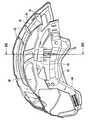
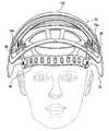
以下、保護ヘルメット30の内装構造体について、特に図1〜図3、図6及び図12を参照して詳細に説明する。内装構造体サブアセンブリ40は、保護ヘルメット30における着用者の頭部と接触する部分であり、支持ケージ42と、ヘッドバンド44と、締結ユニット48を備えたネックバンド46とを含む。内装構造体サブアセンブリ40は、着用者の頭部にヘルメット30を装着して固定するために、図3及び図6に示すようにヘルメットシェル36に取り付けることができる。 Hereinafter, the interior structure of the
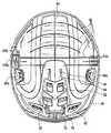
図1は、本発明による保護ヘルメット30の内装構造体サブアセンブリ40を斜め下方から見た斜視図である。図2は、図1の内装構造体サブアセンブリを斜め上方から見た斜視図である。図3は、図1の内装構造体サブアセンブリ40を保護ヘルメット30のヘルメットシェル36に取り付けた状態を示す縦断面図である。図6は、顔面保護具32及び耳保護具34を備えた保護ヘルメット30の一実施形態を示す分解部分断面図である。図12は、保護ヘルメット30の内装構造体サブアセンブリ40を示す図であり、ネック領域においてネックバンド46の2つの端部を締結ユニット48によって着脱自在に締結した状態を示す。 FIG. 1 is a perspective view of an
支持ケージ42は、硬くて、弾性的にフレキシブルな材料、好ましくはポリアミドなどのプラスチック材料から形成される。支持ケージ42は、左右のこめかみ領域及び後頭部領域において斜め下向きまたは斜め後向きに延出して形成された剛性体の支持アーム54、55及び56を有しており、これらのアームにより、内装構造体はヘルメットシェル30に三点で取り付けられる。また、これらのアームにより、耳保護具32の耳覆い部材35a、35b、他のヘルメット付属品並びに顔面及び耳保護具32、34の取付具80、84を収容することができる間隙60が、ヘルメットシェル36と内装構造体との間に形成される。本明細書で説明する実施形態では、支持ケージ42は、一体形成されたプラスチック成型品として作製される。図2に示すように、支持ケージ42は、互いに離間配置された一対の帯状の支持ストリップ142と、互いに離間配置された一対の帯状の支持ストリップ144とをそれらの中央部分において互いに交差させ、各支持ストリップの端部を4箇所の接続点146a、146b、146c、146dにおいて、周縁が閉じた形状の単一の支持ストリップ148と一体化させることにより形成される。図1では、支持ストリップ142、144は十字形の当て物材料の部材149によって覆われている。 The
支持アーム54、55、56は、接続点146a、146b、146c、146dで支持ケージ42から延出して形成されている。支持ストリップ142、144が湾曲して延在しており、好ましくは連結点146a、146b、146c、146d間で実質的に円弧を描くように延在している仮定すると、支持アーム54、55、56は、図15または図2に見ることができるように、それぞれ支持ケージ142から下向きまたは後向きに、それに関連する円弧の実質的に接線方向に延出して形成されている。本明細書で説明する実施形態では、支持アーム54、55、56は、周縁が閉じた形状の支持ストラップ148と一体的に形成されている。図2に示すように、ヘッドバンド44は、支持ケージ42と一体的に形成されている。ネックバンド46は、詳細には図示していないが例えばスナップ結合によってヘッドバンド44の後側の遊端に対して着脱自在に結合される、2つの前側端部を有している。図1〜3に示すように、ネックバンド46は、ネック領域において着脱自在に、すなわち図12に示すように締結ユニット48によって締結可能な2つの遊端を有している。ネックバンド46は、支持ケージ42と同じ材料から形成することができる。例えば図1及び図2に示すように、ネックバンド46は、高さを調節できるようにして、ヘッドバンド44に結合される前側端部と前記遊端との間に位置する部分で支持ケージ42にそれぞれ結合されている。この目的のために、支持ケージ42は、下向きに延出して形成された2つの連結アーム47a、47bを有しており、連結アーム47a、47bによってネックバンド46を選択された高さでそれぞれ固定することができる。左右両側の各ネックバンド46は、上下方向に並んで配置された3つの係合孔51を有しており、これらの係合孔51を、図1及び図2に示すように、各連結アーム47a、47bに突設された弾性ボルト49(図6)と係合させることができる。 The
上述の実施形態では、支持アーム54、55は、実際には、支持アーム56とは異なる方式でヘルメットシェル36に結合されるが、このことは必須ではない。支持アーム54、55は、支持アーム56と同じ方式でヘルメットシェルに結合させてもよい。必要なのは、支持アーム54、55が、支持アーム56と同じように、支持アーム54、55をヘルメットシェル36に確実に結合させることができる結合手段を備えていることだけである。この場合、支持アーム54、55の結合手段は、例えば、支持アーム56と同様の、ヘルメットシェル36のスロットに挿入して係合結合させることによって支持アーム54、55をヘルメットシェルに結合させる係合結合手段であってもよい。 In the embodiment described above, the
ヘッドバンド44は、連結ストリッブ150を介して周縁が閉じた形状の支持ストリップ148と一体的に形成され、かつ支持ストリップ148に対して所定の距離で離間している。また、支持アーム54、55、56及び連結アーム47a、47bは、それらと一体的に形成されたリブ152、154によって補強されている。 The
左右のこめかみ領域において下向きに延出して形成された支持アーム54、55は、該支持アームをヘルメットシェル36の内面に結合させるための結合手段を有する。前記結合手段は、各支持アーム54、55に設けられた3つの貫通孔156、158を含み、これらの貫通孔は、ヘルメットシェル36に設けられた棒状突出体74a、74bと確実に係合することができる。後頭部領域において後向き延出して形成された支持アーム56は突起部分56a、56bを有しており、これらの突起部分は既に上述したように、内装構造体サブアセンブリ40をヘルメットシェル36に着脱自在に結合させるための結合機構を構成する。 The
図2を参照して、顎ストラップ(図示せず)を取り付けるための取付具88a、88bが支持ケージ42に形成されている。顎ストラップの取付具88a、88bは2つの枢動ピン90a、90bを含み、これらの枢動ピンは、左右のこめかみ領域で下方向に延出して形成された支持アーム54、55に隣接する位置において支持ケージ42の周縁が閉じた形状の環状支持ストリップ148と一体的に形成されるか、または図示のように環状支持ストリップ148にスナップ結合により取り付けられた取付部材89a、89b上に設けられる。 Referring to FIG. 2,
工場作業者や森林作業者用のヘルメットでは、顎ストラップ(図示せず)は、ヘルメットシェルまたは支持ケージ42に取り付けられる。登山用のヘルメットでは、顎ストラップは、ヘルメットシェルにのみ取り付けられる。 In a helmet for factory workers or forest workers, a chin strap (not shown) is attached to a helmet shell or
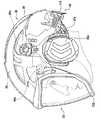
既に部分的に上述したヘルメットシェル36と内装構造体サブアセンブリ40との相互結合について、図2、図3及び図15を参照して要約及び補足説明する。図2は、内装構造体サブアセンブリ40を斜め上方から見た斜視図である。図3は、内装構造体サブアセンブリ40を保護ヘルメット30のヘルメットシェル36に取り付けた状態を示す縦断面図であり、ネックバンド46に設けられた締結ユニット48は図示していない。 The mutual coupling of the
図15は、図3のXV−XV線に沿って切断した保護ヘルメット30の断面図であり、締結ユニット48も図示している。図2では、スペーサとして形成された支持アーム55及び56を見ることができる。下向きに延出して形成された他方の支持アーム55は、図2では見ることができない。支持アーム55は、図3に示されている。図15では、支持アーム54及び55の断面が示されている。内装構造体サブアセンブリ40をヘルメットシェル36に三点で取り付けるために、後向きに延出して形成された支持アーム56を、該支持アームの突起部分56a、56bをヘルメットシェルのスロット78にヘルメットシェルの外面と係合するまで挿入する。次に、内装構造体サブアセンブリ40をヘルメットシェル36の内面にさらに接近させて、支持アーム54、55の貫通孔156、158にヘルメットシェルの棒状突出体74a、74bを挿入させる。このことにより、図15に示すように、支持アーム54、55の貫通孔156、158に棒状突出体74a、74が確実に係合される。ヘルメットシェル36と棒状突出体74a、74bとの間のナックル部において支持アーム54、55をヘルメットシェルの内面に隣接させたとき、棒状突出体74a、74b上にコネクタ136a、136b(図4及び図5)を嵌め込み、これにより支持アーム54及び55を所定の位置に固定する。このようにして、内装構造体サブアセンブリ40及びヘルメットシェル36は、三点で互いに結合される。保護ヘルメット30を着用者の頭部に装着し、締結ユニット48によって頭部に固定した後、必要であれば、顎ストラップ(図示せず)を追加し、顎の下で結んで固定する。支持アーム54、55の貫通孔156、158は、棒状突出体74a、74bにおける貫通孔156、158の内側幅以上の幅を有する部分と係合する。上側からヘルメット30に作用する負荷に起因して支持アーム54、55、56に力が加わったとき、支持アームの遊端で支持されたヘルメットシェル36によって、支持アームに引張荷重が加わる。支持アーム54、55、56に作用する力によって、ヘルメットシェル36をその下側縁部まで内向きに変形させようとするモーメントが、前記三点(ヘルメットシェルと支持アームの結合点)のそれぞれにおいて生成される。このようにして、ヘルメットシェル36はそれに作用する力の一部を変形エネルギーに変換し、これによりヘルメットの着用者に作用する力の影響を低減させることができる。支持アーム54、55、56からヘルメットシェル36への前記モーメントの伝達は、支持アームをそれと一体的に形成されたリブ152によって補強することによって、さらに向上させることができる。 FIG. 15 is a cross-sectional view of the
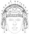
以下、耳保護具34及びその取付具80について、添付図面、特に図4〜11を参照して詳細に説明する。図4は、内装構造体サブアセンブリ40を取り付けていない状態のヘルメットシェル36を下方から見た図であり、ヘルメットシェル36の内面に設けられた耳保護具支持部80a、80bの位置がよく見える。図5は、図4のヘルメットシェル36を斜め下方から見た斜視図である。図6は、保護ヘルメット30の分解部分断面図であり、耳保護具34が他のヘルメット付属品と共に示されている。図7は、保護ヘルメット30の底面図であり、耳保護具34はヘルメットから離して示している。明瞭化のために、図7では、ヘルメットの反対側に設けられる左右対称的な耳保護具34は省略している。図8は、左右両側に耳保護具を備えた保護ヘルメット30を示す図であり、ヘルメットシェル36は断面図で示しており、耳保護具34を回動変位させて耳から離した状態を示す。図9は、図8の保護ヘルメットを示す図であり、耳保護具34を回動変位させて耳にあてた状態を示す。図10は、図9の保護ヘルメットを示す側面図である。図11は、図10の保護ヘルメットを示す図であり、耳保護具34を後向きに回動させて待機位置へ変位させ、ヘルメットシェルの内側に収容した状態を示す。 Hereinafter, the
耳保護具34は、2つの耳覆い部材35a、35bと、2つの耳覆い部材35a、35bを各々回転可能に支持する2つのフォーク様支持ブラケット37a、37bとを含む。図4に見ることができるように、ヘルメットシェル36の内面に、耳保護具支持部80a、80bが設けられている。図6では耳保護具支持部80bは支持ケージ42と一体的に示されているが、耳保護具支持部80bは実際には支持ケージ42ではなく、ヘルメットシェル36の内面に設けられる(耳保護具支持部80aも同様である)。図6は、内装構造体サブアセンブリ40の支持ケージ42に対する耳保護具支持部80bの位置を示すことを目的としている。図10及び図11に見ることができるように、耳覆い部材35a、35bを保持した支持ブラケット37a、37bが、耳保護具支持部80a、80bによって回動可能に支持されている。耳保護具支持部80a、80b及び支持ブラケット37a、37bは、支持ブラケット37a、37bを間隙60内で2つの位置、すなわち図9及び図10に示す耳覆い部材35a、35bが耳を覆う使用位置と、図11に示す耳覆い部材35a、35bがヘルメットシェル36の間隙60に収容される待機位置との間で回動変位させることができるように構成され配置されている。 The
各支持ブラケット37a、37bは、図8に示すような各支持ブラケットの曲げていない位置において耳覆い部材35a、35bをそれぞれ回動変位させて耳から離間させることができ、かつ図9に示すような各支持ブラケットの曲げた位置において各耳覆い部材35a、35bをそれぞれ回動変位させて耳に当てることができるように、ばね付勢され、かつ間隙60内に延在するその両端間の領域で曲げることができるように形成されている。保護ヘルメット30がユーザの頭部に装着されていない場合、2つの耳覆い部材35a、35bはそれぞれ、それが当てられる耳の位置よりもはるかに内側に位置する前記曲げた位置に達する。言い換えれば、このときの耳覆い部材間の距離は、耳の間の距離よりも実質的に小さくなる。このようにして、ヘルメット30の装着時は、ばね付勢によって耳覆い部材35a、35bを耳に押し付けた状態に維持することができる。2つの規定された位置の間で各支持ブラケット37a、37bを曲げるためのばね付勢は、円形に曲げたヨークばね92a、92b(図6)によって実現される。各支持ブラケット37a、37bは、曲げた位置及び曲げていない位置へ手動で変位させることができる。これらの各位置では、ヨークばね92a、92bによって終端位置ロックをもたらすことができる。ヘルメットの着用時は、上述したように各耳覆い部材35a、35bは耳に弾性的に押し付けた状態に維持されるので、支持ブラケット37a、37bの終端位置ロックには達しない。 Each of the
さらに、各耳保護具支持部80a、80b及び各支持ブラケット37a、37bは、支持ブラケットが図8に示した位置から後向きにのみ回動することができるように構成される。このことにより、耳覆い部材35a、35bを、耳及びヘルメットシェル36の下側縁部と衝突することなく、耳の後ろ側の間隙内に収容することができる。 Further, the ear
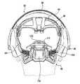
以下、顔面保護具32について、特に図6〜7及び図17〜20を参照してより詳細に説明する。図6は、保護ヘルメット30の分解部分断面図であり、顔面保護具32が他のヘルメット付属品と共に示されている。図7は、保護ヘルメット30の底面図であり、顔面保護具32のバイザー132はヘルメットから離して示している。図17は、バイザー132を開いた状態の保護ヘルメット30を示す図である。図18は、図17の保護ヘルメットを前方から見た断面図である。図19は、図17の保護ヘルメットを後方から見た破断図である。図20は、顔面保護具32に加えて、耳保護具34と、後頭部領域においてネックバンド46に取り付けられた締結ユニット48とを備えた保護ヘルメット30の一実施形態を示す側面図である。 Hereinafter, the
顔面保護具32は、2つのバイザー支持アーム32a、32bと、2つのコネクタ136a、136bとを有するバイザー132を含み、コネクタ136a、136bには、顔面保護具32の取付具84としての顔面保護具支持部84a、84bが一体的に設けられている。コネクタ136a、136bは棒状突出体74a、74b上に嵌め込まれ、これにより、顔面保護具支持部84a、84bはヘルメットシェル36の内面のこめかみ領域に配置されることとなる。顔面保護具支持部84bを有するコネクタ136bを、図4に見ることができる。顔面保護具支持部84aを有し、コネクタ136bの反対側に配置されるコネクタ136aは、図4では示されていない。各顔面保護具支持部84a、84bは、回転軸方向に突出する、かつ弾性的にフレキシブルな3つのタペット85a、85bを有しており、このタペット85a、85bを介して、リング状ベアリングブッシュ134a、134bを有するバイザー支持アーム132a、132bが顔面保護具支持部84a、84bに着脱自在かつ回動可能に取り付けられる。顔面保護具支持部84a、84b及びバイザー支持アーム132a、132bは、各支持アーム132a、132bを間隙60内で2つの位置、すなわちバイザー132を閉じた着用者の顔面を覆って保護する状態の使用位置(図20)と、バイザー132を開いた状態のヘルメットシェル36の外面に密接に隣接する待機位置(図17及び19)との間で回動させることができるように構成され配置される。顔面保護具の取付具84は、バイザー支持アーム132a、132bのための自己保持マウント部を有している。この目的のために、各バイザー支持アーム136a、136bは、バイザー支持アーム132a、132bに取り付けられたリング状ベアリングブッシュ134a、134bを使用位置または待機位置において弾性付勢された状態で保持するためのばね付勢ボルトを有している。 The
バイザー132は、各バイザー支持アーム132a、132b(図6)と共に、バイザーを開いたときに(図17)ヘルメットシェル36の周縁部を密接に収容することができるフォーク状部材を形成する。バイザー132を閉じたとき、バイザー132の上側縁部はヘルメットシェル36の前側縁部に隣接し、バイザーの側方縁部はヘルメットシェルの外面に隣接する。したがって、保護ヘルメットの使用時(例えば森林作業時)は、バイザーを閉じている場合でも開いている場合でも、木の枝がバイザー132やバイザー支持アーム132a、132bに引っ掛かってヘルメットの着用者を危険にさらすことが生じない。 The
以下、締結ユニット48について、より詳細に説明する。締結ユニット48は耳保護具34と同様なヘルメット付属品であって、締結ユニット48の領域において障害物に引っ掛かるおそれがある突出部分が存在しないように、耳保護具34と共に常にヘルメットシェル36の周縁部の内側に位置する。締結ユニット48について、特に図12〜16を参照して説明する。図12は、保護ヘルメット30の内装構造体サブアセンブリ40を示す側面図であり、ネック領域においてネックバンド46の2つの端部を締結ユニット48によって着脱自在に締結した状態を示す。図13は、図12の内装構造体サブアセンブリをヘルメットシェル36に取り付けた状態を示す側面図であり、図12のような締結状態の締結ユニット48が示されている。図14は、図13の保護ヘルメット30を下方から見た図である。図15は、保護ヘルメット30を前方から見た断面図である。図16は、図13の保護ヘルメット30を後方から見た部分破断図である。 Hereinafter, the
締結ユニット48はマウント部168を含み、マウント部168の左右両端にネックバンド46の遊端が挿入される。マウント部168は、ネックバンド46の複数の傾斜係合孔176と係合可能な傾斜係合ノブを有している。このことにより、ネックバンド46の長さを、着用者の頭部のサイズに応じて大まかに調節することができる。この調節は、締結ユニットを機能させていないときに保護ヘルメット30を簡単にかぶることができるように適切に行われる。ヘルメット30をかぶった後のネックバンド46の締結は、以下に説明するようにして締結ユニット48により行う。 The
図14に示すように、支持シェル172及びマウント部168が、伝達レバー169によって互いにジョイント結合されている。図14を参照して、伝達レバー169の一端部が、ジョイント170(図12)によって支持シェル172の下端部に連結されている。図16を参照して、伝達レバー169の他端部が、ジョイント171によって、マウント部168の上端部に連結されている。 As shown in FIG. 14, the
締結ユニット48は、ジョイント173によってマウント部168に連結されたロック用フラップ174(図12)によって操作される。ロック用フラップ174は、ジョイント173の下側に位置し、その側方に伝達レバー169が隣接するタペット(図示せず)を有する。図12に示すようにロック用フラップ174を閉じた場合、伝達レバー169へのタペットの作用により、マウント部168の下端部が後向きに回動して、ジョイント170から遠ざかる。この回動により、ネックバンド46が締結される。この過程では、締結ユニット48は、ネック領域において、支持シェル172によって着用者の後頭部に支持される。図示しないばねがジョイント171に対応して設けられており、前記ばねは、ロック用フラップ174を開いたときに伝達レバー169のジョイント170をマウント部168の下側縁部に向けて付勢するために、マウント部168と伝達レバー169との間に配置される。支持シェル172の上端部がマウント部168の上端部から離間する方向に回動変位したストッパ位置に支持シェル172を付勢するために、ジョイント170の領域において、別のばね(図示しない)が支持シェル172と伝達レバー169の間に設けられる。 The
締結ユニット48の機能は、ロック用フラップ174によって発揮される。ロック用フラップ174を時計回りに回動させて閉じると(図12)、マウント部168がジョイント171を中心にして回動変位し、支持シェル172の下側縁部がマウント部168の下側縁部から離間する。これは、締結ユニットの締結位置であり、図12〜14に見ることができる。ロック用フラップ174を反時計回りに回転させて開くと、締結ユニット48は開状態になる。その結果、マウント部168の下側縁部は、支持シェル172に設けられたジョイント170に向かって変位し、これによりネックバンド46が解放され、保護ヘルメット30の着脱が可能となる。保護ヘルメット30をかぶったときは、ロック用フラップ174を下向きに回動させるだけで、保護ヘルメット30を着用者の頭部に固定することができる。このことは、着用者が片手で、また手袋をしていても、簡単に行うことができる。支持シェル172の前側は、当て物材料の部材180で覆われている。 The function of the
30 保護ヘルメット
32 顔面保護具
34 耳保護具
35a 耳覆い部材
35b 耳覆い部材
36 ヘルメットシェル
37a 支持ブラケット
37b 支持ブラケット
40 内装構造体サブアセンブリ
42 支持ケージ
44 ヘッドバンド
46 ネックバンド
47a 支持アーム
47b 支持アーム
48 締結ユニット
49 ボルト
50 通気スライド部材
51 係合孔
52 通気オリフィス
53 通気オリフィス
54 支持アーム
55 支持アーム
56 支持アーム
56a 突起部分
56b 突起部分
60 間隙
62 補強リブ
64 補強リブ
66 前側ガイドスロット
68 前側係合突起
70 後側係合突起
72 後側ガイドスロット
74a 棒状突出体
74b 棒状突出体
76 凹部
78 スロット
80 耳保護具の取付具
80a 耳保護具支持部
80b 耳保護具支持部
84 顔面保護具の取付具
84a 顔面保護具支持部
84b 顔面保護具支持部
85a タペット
86b タペット
88a 顎ストラップの取付具
88b 顎ストラップの取付具
89a 取付部材
89b 取付部材
90a 枢動ピン
90b 枢動ピン
92a ヨークばね
92b ヨークばね
132 バイザー
132a 保持アーム
132b 保持アーム
134a リング状ベアリングブッシュ
134b リング状ベアリングブッシュ
136a コネクタ
136b コネクタ
142 支持ストリップ
144 支持ストリップ
146a 接続点
146b 接続点
146c 接続点
146d 接続点
148 支持ストリップ
149 当て物材料
150 連結ストリップ
152 リブ
154 リブ
156 貫通孔
158 貫通孔
168 支持シェルのマウント部
169 伝達レバー
170 ジョイント
171 ジョイント
172 支持シェル
173 ジョイント
174 ロック用フラップ
176 傾斜係合孔
180 当て物材料の部材DESCRIPTION OF SYMBOLS 30 Protective helmet 32 Face protector 34 Ear protector 35a Ear cover member 35b Ear cover member 36 Helmet shell 37a Support bracket 37b Support bracket 40 Interior structure subassembly 42 Support cage 44 Headband 46 Neckband 47a Support arm 47b Support arm 48 Fastening unit 49 Bolt 50 Ventilation slide member 51 Engagement hole 52 Ventilation orifice 53 Ventilation orifice 54 Support arm 55 Support arm 56 Support arm 56a Protrusion portion 56b Protrusion portion 60 Gap 62 Reinforcement rib 64 Reinforcement rib 66 Front guide slot 68 Front engagement protrusion 70 Rear engagement protrusion 72 Rear guide slot 74a Rod-like protrusion 74b Rod-like protrusion 76 Recessed portion 78 Slot 80 Ear protector attachment 80a Ear protector support portion 80b Ear protector Tool support part 84 Face protector mounting tool 84a Face protector support part 84b Face protector support part 85a Tappet 86b Tappet 88a Jaw strap mounting tool 88b Jaw strap mounting tool 89a Mounting member 89b Mounting member 90a Pivoting pin 90b Pivot Moving pin 92a Yoke spring 92b Yoke spring 132 Visor 132a Holding arm 132b Holding arm 134a Ring bearing bush 134b Ring bearing bush 136a Connector 136b Connector 142 Support strip 144 Support strip 146a Connection point 146b Connection point 146c Connection point 146d Connection point 148 Support Strip 149 Pad material 150 Connecting strip 152 Rib 154 Rib 156 Through-hole 158 Through-hole 168 Support shell mounting portion 16 DESCRIPTION OF SYMBOLS 9 Transmission lever 170 Joint 171 Joint 172 Support shell 173 Joint 174 Locking flap 176 Inclined engagement hole 180 Member of pad material
Claims (16)
Translated fromJapaneseヘルメットシェルと、
少なくともヘッドバンド、ネックバンド、及び複数の支持ストリップを含み、着用者の頭部に装着される内装構造体サブアセンブリと、
前記内装構造体サブアセンブリを前記ヘルメットシェルに結合させるための結合手段とを含んでおり、
前記複数の支持ストリップは、支持ケージを形成し、
前記結合手段が、スペーサとして形成され、かつ前記支持ケージと一体的に形成された少なくとも3つの支持アームを含み、前記支持アームは、剛性体であり、後頭部領域及び左右のこめかみ領域において前記支持ケージから斜め後向きまたは斜め下向きに延出しており、
前記ヘルメットシェル及び前記支持アームが、前記内装構造体サブアセンブリ及び前記ヘルメットシェルの間に、前記内装構造体サブアセンブリの周囲に連続的に延在する間隙であって、少なくとも耳保護具の耳覆い部材及び支持ブラケットを含むヘルメット付属品、並びに少なくとも顔面保護具及び耳保護具を含むその他のヘルメット付属品のための取付具を収容する、前記間隙が形成されるような寸法に形成され配置されており、
前記ヘルメットシェルの内面の左右のこめかみ領域において下向きに突出する棒状突出体が形成されており、
前記左右のこめかみ領域における前記支持アームに前記棒状突出体が貫通し係合可能な貫通孔が形成されており、かつ
前記ヘルメット付属品の少なくとも1つのための取付具が、前記支持アームの前記貫通孔を貫通し係合した前記棒状突出体上に嵌合されるコネクタによって前記保護ヘルメットに結合されていることを特徴とする保護ヘルメット。A protective helmet,
Helmet shell,
An interior structure subassembly that includes at least a headband, a neckband, and a plurality of support strips and is attached to a wearer's head;
Coupling means for coupling the interior structure subassembly to the helmet shell;
The plurality of support strips form a support cage;
The coupling means includes at least three support arms formed as spacers and integrally formed with the support cage, the support arms being rigid bodies, and the support cage in the occipital region and the left and right temple regions Extends diagonally backwards or diagonally downwards,
The helmet shell and the support arm are gaps extending continuously around the interior structure subassembly between the interior structure subassembly and the helmet shell, and at least the ear covering of the ear protector Held and arranged to be dimensioned so that the gap is formed to accommodate a helmet accessory including a member and a support bracket, and a fixture for at least other helmet accessories including a face protector and an ear protector.And
A rod-like protrusion that protrudes downward in the left and right temple regions on the inner surface of the helmet shell is formed,
The support arm in the left and right temple regions is formed with a through-hole through which the rod-like projecting body can be engaged, and
A fixture for at least one of the helmet accessories is coupled to the protective helmet by a connector that fits over the rod-like projection that has penetrated and engaged the through-hole of the support arm. Protective helmet.
前記支持ケージが、硬くて、弾性的にフレキシブルな材料から形成されており、
前記支持アームの遊端が前記ヘルメットシェルにそれぞれ結合されるように構成されていることを特徴とする保護ヘルメット。The protective helmet according to claim 1,
The support cage is formed of a hard, elastically flexible material;
A protective helmet, wherein the free ends of the support arms are respectively coupled to the helmet shell.
前記耳保護具の前記取付具が、前記ヘルメットシェルの内面に配置され、かつ前記耳覆い部材を保持する左右2つの前記支持ブラケットをそれぞれ回動可能に支持する左右2つの耳保護具支持部を含むことを特徴とする保護ヘルメット。The protective helmet according to claim 1 or 2,
The left and right ear protector support portions that are disposed on the inner surface of the helmet shell and that support the left and right two support brackets that hold the ear covering member so as to be rotatable, respectively, are mounted on the ear protector. Protective helmet, characterized by including.
前記耳保護具支持部及び前記支持ブラケットが、前記支持ブラケットを前記間隙内で、前記耳覆い部材が着用者の耳を覆う使用位置と、前記耳覆い部材が前記間隙に収容される待機位置との間で回動変位させることができるように構成され配置されていることを特徴とする保護ヘルメット。The protective helmet according to claim 3,
The ear protector support part and the support bracket include a use position in which the support bracket is placed in the gap, the ear cover member covers a wearer's ear, and a standby position in which the ear cover member is accommodated in the gap. A protective helmet characterized in that it is constructed and arranged so that it can be pivotally displaced between the two.
前記顔面保護具が、バイザー及び該バイザーを支持する左右2つのバイザー支持アームを含み、
前記顔面保護具の前記取付具が、前記ヘルメットシェルの内面に配置され、かつ左右2つの前記バイザー支持アームをそれぞれ回動可能に支持する左右2つの顔面保護具支持部を含むことを特徴とする保護ヘルメット。A protective helmet according to any one of claims 2 to 4,
The face protection device includes a visor and two left and right visor support arms that support the visor,
The attachment device of the face protector includes two left and right face protector support portions that are disposed on an inner surface of the helmet shell and rotatably support the left and right visor support arms. Protective helmet.
前記顔面保護具支持部及び前記バイザー支持アームが、前記バイザー支持アームを前記間隙内で、前記バイザーが着用者の顔面を覆って保護する使用位置と、前記バイザーが前記ヘルメットシェルの外面に密接に隣接して配置される待機位置との間で回動変位させることができるように構成され配置されていることを特徴とする保護ヘルメット。The protective helmet according to claim 5,
The face protector support and the visor support arm are used to protect the visor support arm in the gap and the visor covers and protects the wearer's face, and the visor is in close contact with the outer surface of the helmet shell. A protective helmet configured and arranged so as to be able to be rotationally displaced between standby positions arranged adjacent to each other.
前記支持ケージが、その下側縁部に、周縁が閉じた形状の支持ストリップを含み、
前記支持ストリップに前記支持アームが一体的に形成されていることを特徴とする保護ヘルメット。A protective helmet according to any one of claims 2 to 6,
The support cage includes a support strip with a closed periphery at its lower edge;
A protective helmet, wherein the support arm is integrally formed with the support strip.
前記ネックバンドが、前記支持ケージに結合されており、かつネック領域において前記ネックバンドの2つの端部を互いに締結するための締結ユニットを備えており、
前記締結ユニットが前記間隙内に収容されていることを特徴とする保護ヘルメット。The protective helmet according to claim 7,
The neckband is coupled to the support cage and includes a fastening unit for fastening the two ends of the neckband to each other in the neck region;
The protective helmet, wherein the fastening unit is accommodated in the gap.
前記締結ユニットが、
前記ネックバンドを締結するためのロック用フラップと、
前記ネックバンドを前記ロック用フラップによって締結したときに、ヘルメットの着用者の後頭部を当接支持する支持シェルとを有していることを特徴とする保護ヘルメット。The protective helmet according to claim 8,
The fastening unit is
A locking flap for fastening the neckband;
A protective helmet comprising a support shell for abutting and supporting the back of the head of a helmet wearer when the neckband is fastened by the locking flap.
左右のこめかみ領域において下向きに延出して形成された前記支持アームが、該支持アームを前記ヘルメットシェルの内面に着脱自在に結合させるための結合手段を有していることを特徴とする保護ヘルメット。A protective helmet according to any one of claims 2 to 9,
A protective helmet, wherein the support arm formed extending downward in the left and right temple regions has a coupling means for detachably coupling the support arm to the inner surface of the helmet shell.
前記支持アームの前記結合手段が、該支持アームを前記ヘルメットシェルの内面に確実に結合させることができるように構成されていることを特徴とする保護ヘルメット。The protective helmet according to claim 10,
2. The protective helmet according to claim 1, wherein the coupling means of the support arm is configured so that the support arm can be securely coupled to the inner surface of the helmet shell.
後頭部領域において後向きに延出して形成された前記支持アームが、該支持アームをヘルメットシェルに結合させるための結合手段を有していることを特徴とする保護ヘルメット。A protective helmet according to any one of claims 2 to 11,
A protective helmet characterized in that the support arm formed to extend rearward in the occipital region has a coupling means for coupling the support arm to a helmet shell.
前記顔面保護具支持部が、前記支持アームの前記の貫通孔と係合した前記棒状突出体上に嵌合される前記コネクタによって前記保護ヘルメットに結合されていることを特徴とする保護ヘルメット。The protective helmet according to claim 5,
Protective helmets the face protection supporting unit, characterized inthat it is coupled to the protective helmet bysaid connector to be fitted to the support arm of the through-hole and engaged with the rod-shaped projecting member.
前記棒状突出体が、前記棒状突出体における前記貫通孔の内側幅以上の幅を有する幅広部分を有し、
前記貫通孔が、前記棒状突出体における前記貫通孔の内側幅以上の幅を有する前記幅広部分と係合するように構成し
上側から前記ヘルメットシェルに作用する負荷に起因する力が、前記棒状突出体を介して前記支持アームに加えられることを特徴とする保護ヘルメット。A protective helmet according toanyone of claims1 to 13,
The rod-shaped protrusion has a wide portion having a width equal to or larger than the inner width of the through hole in the rod-shaped protrusion;
The through hole is configured to engage with the wide portion having a width equal to or larger than the inner width of the through hole in the rod-like projecting body, and the force caused by the load acting on the helmet shell from above is the rod-like projection. A protective helmet, which is applied to the support arm through a body.
前記支持ケージが、下向きに延出して形成され、かつ前記ネックバンドと選択された高さで各々結合可能な2つの連結アームを有することを特徴とする保護ヘルメット。A protective helmet according to any one of claims 1 to 14,
2. The protective helmet according to claim 1, wherein the support cage has two connecting arms that extend downward and are connectable to the neckband at a selected height.
前記支持アーム及び前記連結アームが、それらと一体的に形成したリブによって補強されていることを特徴とする保護ヘルメット。The protective helmet according to claim 15,
The protective helmet, wherein the support arm and the connecting arm are reinforced by ribs formed integrally therewith.
Applications Claiming Priority (3)
| Application Number | Priority Date | Filing Date | Title |
|---|---|---|---|
| DE201010027012DE102010027012A1 (en) | 2010-07-13 | 2010-07-13 | Hard hat, especially for forestry workers |
| DE102010027012.1 | 2010-07-13 | ||
| PCT/EP2011/061879WO2012007472A1 (en) | 2010-07-13 | 2011-07-12 | Protective helmet, in particular for forestry workers |
Publications (2)
| Publication Number | Publication Date |
|---|---|
| JP2013531146A JP2013531146A (en) | 2013-08-01 |
| JP6046613B2true JP6046613B2 (en) | 2016-12-21 |
Family
ID=44510084
Family Applications (1)
| Application Number | Title | Priority Date | Filing Date |
|---|---|---|---|
| JP2013519075AActiveJP6046613B2 (en) | 2010-07-13 | 2011-07-12 | Protective helmet |
Country Status (23)
| Country | Link |
|---|---|
| US (1) | US9179728B2 (en) |
| EP (1) | EP2498636B8 (en) |
| JP (1) | JP6046613B2 (en) |
| KR (1) | KR101906608B1 (en) |
| CN (1) | CN103052330B (en) |
| AU (1) | AU2011278393B2 (en) |
| BR (1) | BR112013000588B1 (en) |
| CA (1) | CA2804406C (en) |
| CL (1) | CL2013000118A1 (en) |
| DE (1) | DE102010027012A1 (en) |
| DK (1) | DK2498636T3 (en) |
| EA (1) | EA020680B1 (en) |
| ES (1) | ES2428085T3 (en) |
| HR (1) | HRP20130837T1 (en) |
| MX (1) | MX2013000458A (en) |
| MY (1) | MY162952A (en) |
| NZ (1) | NZ606373A (en) |
| PE (2) | PE20150304A1 (en) |
| PL (1) | PL2498636T3 (en) |
| SI (1) | SI2498636T1 (en) |
| UA (1) | UA109444C2 (en) |
| WO (1) | WO2012007472A1 (en) |
| ZA (1) | ZA201300327B (en) |
Families Citing this family (31)
| Publication number | Priority date | Publication date | Assignee | Title |
|---|---|---|---|---|
| DE102012000370B4 (en)* | 2012-01-11 | 2017-02-02 | Pfanner Schutzbekleidung Gmbh | Hard hat, especially for mountaineers and tree climbers |
| DE102012103528A1 (en) | 2012-04-20 | 2013-10-24 | Pfanner Schutzbekleidung Gmbh | headband |
| DE202012101489U1 (en) | 2012-04-20 | 2012-05-09 | Anton Pfanner | headband |
| US9554610B2 (en)* | 2012-10-11 | 2017-01-31 | Honeywell International, Inc. | Protective headgear assembly |
| ITMI20131005A1 (en)* | 2013-06-18 | 2014-12-19 | Kask S R L | PROTECTIVE ANTISCALIZATION HELMET, IN PARTICULAR FOR SPORTS USE |
| US9949522B2 (en)* | 2013-08-30 | 2018-04-24 | Msa Technology, Llc | Suspension connection arrangement for a suspension system of a safety helmet |
| DE102013017830A1 (en) | 2013-10-24 | 2015-04-30 | Pfanner Schutzbekleidung Gmbh | Protective goggles for attachment to a protective helmet and safety helmet equipped with goggles |
| DE202013011222U1 (en) | 2013-12-13 | 2015-03-20 | Pfanner Schutzbekleidung Gmbh | Neck protector and protective helmet equipped with it |
| USD729458S1 (en) | 2014-05-02 | 2015-05-12 | 3M Innovative Properties Company | Ear muff attachment housing |
| USD741550S1 (en) | 2014-05-02 | 2015-10-20 | 3M Innovative Properties Company | Ear muff attachment arm |
| US10959477B2 (en) | 2014-05-02 | 2021-03-30 | 3M Innovative Properties Company | Ear muff attachment having dual axis of rotation |
| AT516055B1 (en)* | 2014-08-06 | 2016-02-15 | Rosenbauer Int Ag | helmet |
| ITUB20154758A1 (en)* | 2015-10-27 | 2017-04-27 | Kask Spa | BAND POGGIA FRONT FOR HELMETS AND HELMET PROVIDED WITH SUCH FRONT POGGIA BAND. |
| US11457684B2 (en)* | 2015-12-24 | 2022-10-04 | Brad W. Maloney | Helmet harness |
| GB2558317A (en)* | 2016-12-22 | 2018-07-11 | Otos Wing Co Ltd | Ergonomic occipital triangular cushion pad for head bands |
| USD827207S1 (en)* | 2017-02-21 | 2018-08-28 | Unit 1 Gear, Inc. | Helmet and headphones |
| USD876017S1 (en)* | 2017-05-10 | 2020-02-18 | 3M Innovative Properties Company | Attachment arm |
| KR20190001043U (en) | 2017-10-24 | 2019-05-03 | 주식회사 연합세이프티 | A helmet with a warm-up pad for removable earmuffs |
| DE102017011565A1 (en) | 2017-12-14 | 2019-06-19 | Francesco Monteleone | Hard hat with integrated filter |
| WO2019127030A1 (en)* | 2017-12-26 | 2019-07-04 | 丰阁行销设计有限公司 | Safety helmet and manufacturing method therefor |
| CN108871072B (en)* | 2018-09-27 | 2024-03-26 | 北京金箭工程技术研究院 | Tactical helmet |
| US10912344B2 (en)* | 2018-12-03 | 2021-02-09 | Msa Technology, Llc | Helmet with accessory attachment rail |
| CA3161011A1 (en)* | 2019-12-07 | 2021-06-10 | Loic LABROSSE-GIRARD | Lower protective cage for a helmet and helmet having same |
| USD966620S1 (en)* | 2020-06-04 | 2022-10-11 | Rpb Safety, Llc | Bump cap |
| WO2022197788A1 (en)* | 2021-03-18 | 2022-09-22 | Milwaukee Electric Tool Corporation | Safety headwear systems and coupling mechanisms therefor |
| KR102719463B1 (en)* | 2022-05-04 | 2024-10-18 | (주) 에이치제이씨 | Helmet |
| CN115644549A (en)* | 2022-09-22 | 2023-01-31 | 东莞保民安防有限公司 | Helmet with telescopic ear protection guide rail |
| DE102022134880A1 (en) | 2022-12-28 | 2024-07-04 | Pfanner Schutzbekleidung Gmbh | Helmet light and protective helmet with a helmet light |
| DE102022134902B4 (en) | 2022-12-28 | 2024-09-12 | Pfanner Schutzbekleidung Gmbh | Helmet light and protective helmet with a helmet light |
| US20240315382A1 (en)* | 2023-03-10 | 2024-09-26 | Alan Carlson | Adjustable Head Engaging Apparatus with Display |
| CN116369619A (en)* | 2023-04-24 | 2023-07-04 | 吉林大学 | High-strength helmet with coleopteran bionic structure |
Family Cites Families (34)
| Publication number | Priority date | Publication date | Assignee | Title |
|---|---|---|---|---|
| US3025525A (en)* | 1958-11-24 | 1962-03-20 | Mine Safety Appliances Co | Helmet liner |
| US3156923A (en)* | 1962-06-20 | 1964-11-17 | Mine Safety Appliances Co | Adjustable headgear |
| US3383705A (en)* | 1965-11-26 | 1968-05-21 | Bullard Co | Safety hat suspension system |
| US3619814A (en)* | 1969-12-11 | 1971-11-16 | Gentex Corp | Protective helmet with adjustable headband |
| US3852821A (en)* | 1973-06-11 | 1974-12-10 | L Mickel | Impact absorbent pad for helmet shell |
| DE7510978U (en)* | 1975-04-08 | 1975-07-31 | Roemer H | Hearing protection for a protective helmet, in particular a steel helmet |
| US4069512A (en)* | 1975-05-12 | 1978-01-24 | Tore Georg Palmaer | Locating device for ear-muffs on helmets |
| SE408851B (en) | 1977-07-01 | 1979-07-16 | T G Palmaer | DEVICE IN THE SAFETY HELMET OR A SIMILAR CARRYING BODY |
| DE2907056A1 (en) | 1979-02-23 | 1980-08-28 | Agfa Gevaert Ag | Two-sided film splicing tape - has sprocket holes and alignment slot, with backing pulled-off in film long direction |
| SE8301937L (en) | 1982-05-03 | 1983-11-04 | Peter Karlsson | SKERMANORDNING |
| FR2547704B1 (en)* | 1983-06-24 | 1985-11-29 | Morin Claude | ADVANCED PROTECTIVE HELMET |
| SE455152B (en) | 1984-12-19 | 1988-06-27 | Bo Gunnar Lonnstedt | GUIDELINE FOR FELLABLE FACE PROTECTION ON A SAFETY HELMET |
| JPS6279834U (en)* | 1985-11-07 | 1987-05-21 | ||
| DE8714490U1 (en) | 1987-10-30 | 1988-09-22 | Allit-Plastic-Werk Kimnach GmbH & Co, 55545 Bad Kreuznach | Safety helmet |
| US5105475A (en)* | 1990-07-20 | 1992-04-21 | Countryside Products Co. | Headgear with eyeglass |
| JP3041492B2 (en)* | 1991-08-23 | 2000-05-15 | 日立マクセル株式会社 | Coating method and coating device for coating liquid |
| DE9410596U1 (en)* | 1994-06-30 | 1994-08-25 | Uvex Winter Optik GmbH, 90766 Fürth | Protective device for forest workers or the like. |
| GB2320414B (en)* | 1995-11-30 | 2000-02-23 | David Winstone Aitken Bennett | A safety helmet and method of manufacture |
| DE29708134U1 (en) | 1997-05-06 | 1997-08-14 | Hartfiel, Traudel, 64823 Groß-Umstadt | Eye and face protection for protective helmets |
| DE29710596U1 (en) | 1997-06-18 | 1997-08-21 | Zappel, Werner, 74906 Bad Rappenau | Device for descaling a aerator that can be screwed onto a tap |
| US6081931A (en)* | 1998-03-10 | 2000-07-04 | 3M Innovative Properties Company | Protective helmet suspension system |
| US6298249B1 (en)* | 1998-10-08 | 2001-10-02 | Mine Safety Appliances Company | Radio apparatus head-protective helmet |
| JP2003221724A (en)* | 2002-01-22 | 2003-08-08 | Sumitomo Bakelite Co Ltd | Headband and helmet using the same |
| JP2004032340A (en)* | 2002-06-26 | 2004-01-29 | Temuko Japan:Kk | Bone conduction speaker unit for attaching head mounting means |
| KR100501944B1 (en) | 2003-09-19 | 2005-07-19 | 주식회사 산청 | Safety cap that assembly is easy |
| DE102004004044B4 (en) | 2004-01-27 | 2007-06-28 | Wacker Construction Equipment Ag | helmet |
| US7114197B2 (en)* | 2005-01-14 | 2006-10-03 | Louis Garneau Sport Inc. | Adjustable stabilization strap apparatus |
| DE102006013025B4 (en)* | 2006-03-20 | 2008-01-03 | Schuberth Gmbh | Hard hat and system of a protective helmet |
| JP5140943B2 (en)* | 2006-05-01 | 2013-02-13 | Dicプラスチック株式会社 | helmet |
| US20070261153A1 (en)* | 2006-05-09 | 2007-11-15 | Wise Robert W | Protective helmet with flush pivoting ear cups |
| DE102006040555A1 (en)* | 2006-08-30 | 2008-03-06 | Andreas Stihl Ag & Co. Kg | Protective headgear combination |
| DE102007053190A1 (en)* | 2007-11-06 | 2009-05-07 | Bullard Gmbh | Helmet System |
| KR101236728B1 (en)* | 2010-12-13 | 2013-02-25 | 주식회사 오토스윙 | A hinge structure |
| US8850624B2 (en)* | 2011-05-23 | 2014-10-07 | Honeywell International, Inc. | Headgear with a spring buffered occipital cradle |
- 2010
- 2010-07-13DEDE201010027012patent/DE102010027012A1/ennot_activeWithdrawn
- 2011
- 2011-07-12AUAU2011278393Apatent/AU2011278393B2/enactiveActive
- 2011-07-12WOPCT/EP2011/061879patent/WO2012007472A1/enactiveApplication Filing
- 2011-07-12BRBR112013000588-2Apatent/BR112013000588B1/enactiveIP Right Grant
- 2011-07-12MXMX2013000458Apatent/MX2013000458A/enactiveIP Right Grant
- 2011-07-12CNCN201180034639.6Apatent/CN103052330B/enactiveActive
- 2011-07-12HRHRP20130837ATpatent/HRP20130837T1/enunknown
- 2011-07-12CACA2804406Apatent/CA2804406C/enactiveActive
- 2011-07-12MYMYPI2013700060Apatent/MY162952A/enunknown
- 2011-07-12NZNZ606373Apatent/NZ606373A/enunknown
- 2011-07-12DKDK11730983Tpatent/DK2498636T3/enactive
- 2011-07-12USUS13/808,664patent/US9179728B2/enactiveActive
- 2011-07-12EAEA201300110Apatent/EA020680B1/ennot_activeIP Right Cessation
- 2011-07-12KRKR1020137003443Apatent/KR101906608B1/enactiveActive
- 2011-07-12SISI201130058Tpatent/SI2498636T1/enunknown
- 2011-07-12ESES11730983Tpatent/ES2428085T3/enactiveActive
- 2011-07-12PEPE2014002220Apatent/PE20150304A1/enactiveIP Right Grant
- 2011-07-12JPJP2013519075Apatent/JP6046613B2/enactiveActive
- 2011-07-12PLPL11730983Tpatent/PL2498636T3/enunknown
- 2011-07-12EPEP11730983.1Apatent/EP2498636B8/enactiveActive
- 2011-07-12PEPE2013000069Apatent/PE20131310A1/ennot_activeApplication Discontinuation
- 2011-12-07UAUAA201301669Apatent/UA109444C2/enunknown
- 2013
- 2013-01-11CLCL2013000118Apatent/CL2013000118A1/enunknown
- 2013-01-14ZAZA2013/00327Apatent/ZA201300327B/enunknown
Also Published As
| Publication number | Publication date |
|---|---|
| PL2498636T3 (en) | 2014-01-31 |
| MY162952A (en) | 2017-07-31 |
| HK1184028A1 (en) | 2014-01-17 |
| EP2498636B8 (en) | 2015-10-28 |
| DK2498636T3 (en) | 2013-09-23 |
| BR112013000588A2 (en) | 2020-10-13 |
| EA201300110A1 (en) | 2013-06-28 |
| CN103052330B (en) | 2016-03-16 |
| DE102010027012A1 (en) | 2012-01-19 |
| UA109444C2 (en) | 2015-08-25 |
| CN103052330A (en) | 2013-04-17 |
| US9179728B2 (en) | 2015-11-10 |
| AU2011278393A1 (en) | 2013-02-07 |
| JP2013531146A (en) | 2013-08-01 |
| SI2498636T1 (en) | 2013-11-29 |
| CA2804406A1 (en) | 2012-01-19 |
| EA020680B1 (en) | 2014-12-30 |
| PE20131310A1 (en) | 2013-11-29 |
| WO2012007472A1 (en) | 2012-01-19 |
| AU2011278393B2 (en) | 2016-06-09 |
| CL2013000118A1 (en) | 2013-07-19 |
| NZ606373A (en) | 2015-02-27 |
| KR101906608B1 (en) | 2018-10-10 |
| KR20130135230A (en) | 2013-12-10 |
| EP2498636B1 (en) | 2013-06-19 |
| CA2804406C (en) | 2018-05-01 |
| ZA201300327B (en) | 2014-04-30 |
| HRP20130837T1 (en) | 2013-10-25 |
| US20130205477A1 (en) | 2013-08-15 |
| PE20150304A1 (en) | 2015-03-08 |
| ES2428085T3 (en) | 2013-11-06 |
| BR112013000588B1 (en) | 2021-09-21 |
| MX2013000458A (en) | 2013-12-02 |
| EP2498636A1 (en) | 2012-09-19 |
Similar Documents
| Publication | Publication Date | Title |
|---|---|---|
| JP6046613B2 (en) | Protective helmet | |
| JP6275049B2 (en) | Protective helmet for climbers and climbers | |
| JP6050748B2 (en) | Interior structure for protective helmet | |
| USRE45459E1 (en) | Protective helmet | |
| HK1184028B (en) | Protective helmet, in particular for forestry workers | |
| NZ627152B2 (en) | Safety helmet, in particular for mountain climbers and tree climbers | |
| HK1196925B (en) | Safety helmet, in particular for mountain climbers and tree climbers | |
| HK1196925A (en) | Safety helmet, in particular for mountain climbers and tree climbers |
Legal Events
| Date | Code | Title | Description |
|---|---|---|---|
| A711 | Notification of change in applicant | Free format text:JAPANESE INTERMEDIATE CODE: A711 Effective date:20130417 | |
| A621 | Written request for application examination | Free format text:JAPANESE INTERMEDIATE CODE: A621 Effective date:20140515 | |
| A977 | Report on retrieval | Free format text:JAPANESE INTERMEDIATE CODE: A971007 Effective date:20150324 | |
| A131 | Notification of reasons for refusal | Free format text:JAPANESE INTERMEDIATE CODE: A131 Effective date:20150407 | |
| A521 | Request for written amendment filed | Free format text:JAPANESE INTERMEDIATE CODE: A523 Effective date:20150706 | |
| A131 | Notification of reasons for refusal | Free format text:JAPANESE INTERMEDIATE CODE: A131 Effective date:20160105 | |
| A601 | Written request for extension of time | Free format text:JAPANESE INTERMEDIATE CODE: A601 Effective date:20160405 | |
| A601 | Written request for extension of time | Free format text:JAPANESE INTERMEDIATE CODE: A601 Effective date:20160603 | |
| A521 | Request for written amendment filed | Free format text:JAPANESE INTERMEDIATE CODE: A523 Effective date:20160704 | |
| TRDD | Decision of grant or rejection written | ||
| A01 | Written decision to grant a patent or to grant a registration (utility model) | Free format text:JAPANESE INTERMEDIATE CODE: A01 Effective date:20161101 | |
| A61 | First payment of annual fees (during grant procedure) | Free format text:JAPANESE INTERMEDIATE CODE: A61 Effective date:20161117 | |
| R150 | Certificate of patent or registration of utility model | Ref document number:6046613 Country of ref document:JP Free format text:JAPANESE INTERMEDIATE CODE: R150 | |
| R250 | Receipt of annual fees | Free format text:JAPANESE INTERMEDIATE CODE: R250 | |
| R250 | Receipt of annual fees | Free format text:JAPANESE INTERMEDIATE CODE: R250 | |
| R250 | Receipt of annual fees | Free format text:JAPANESE INTERMEDIATE CODE: R250 | |
| R250 | Receipt of annual fees | Free format text:JAPANESE INTERMEDIATE CODE: R250 | |
| R250 | Receipt of annual fees | Free format text:JAPANESE INTERMEDIATE CODE: R250 | |
| R250 | Receipt of annual fees | Free format text:JAPANESE INTERMEDIATE CODE: R250 |