JP6045953B2 - connector - Google Patents
connectorDownload PDFInfo
- Publication number
- JP6045953B2 JP6045953B2JP2013068465AJP2013068465AJP6045953B2JP 6045953 B2JP6045953 B2JP 6045953B2JP 2013068465 AJP2013068465 AJP 2013068465AJP 2013068465 AJP2013068465 AJP 2013068465AJP 6045953 B2JP6045953 B2JP 6045953B2
- Authority
- JP
- Japan
- Prior art keywords
- receptacle
- outer peripheral
- contact
- connector
- plug
- Prior art date
- Legal status (The legal status is an assumption and is not a legal conclusion. Google has not performed a legal analysis and makes no representation as to the accuracy of the status listed.)
- Active
Links
Images


Classifications
- H—ELECTRICITY
- H01—ELECTRIC ELEMENTS
- H01R—ELECTRICALLY-CONDUCTIVE CONNECTIONS; STRUCTURAL ASSOCIATIONS OF A PLURALITY OF MUTUALLY-INSULATED ELECTRICAL CONNECTING ELEMENTS; COUPLING DEVICES; CURRENT COLLECTORS
- H01R13/00—Details of coupling devices of the kinds covered by groups H01R12/70 or H01R24/00 - H01R33/00
- H01R13/648—Protective earth or shield arrangements on coupling devices, e.g. anti-static shielding
- H01R13/658—High frequency shielding arrangements, e.g. against EMI [Electro-Magnetic Interference] or EMP [Electro-Magnetic Pulse]
- H—ELECTRICITY
- H01—ELECTRIC ELEMENTS
- H01R—ELECTRICALLY-CONDUCTIVE CONNECTIONS; STRUCTURAL ASSOCIATIONS OF A PLURALITY OF MUTUALLY-INSULATED ELECTRICAL CONNECTING ELEMENTS; COUPLING DEVICES; CURRENT COLLECTORS
- H01R12/00—Structural associations of a plurality of mutually-insulated electrical connecting elements, specially adapted for printed circuits, e.g. printed circuit boards [PCB], flat or ribbon cables, or like generally planar structures, e.g. terminal strips, terminal blocks; Coupling devices specially adapted for printed circuits, flat or ribbon cables, or like generally planar structures; Terminals specially adapted for contact with, or insertion into, printed circuits, flat or ribbon cables, or like generally planar structures
- H01R12/70—Coupling devices
- H01R12/71—Coupling devices for rigid printing circuits or like structures
- H01R12/712—Coupling devices for rigid printing circuits or like structures co-operating with the surface of the printed circuit or with a coupling device exclusively provided on the surface of the printed circuit
- H01R12/716—Coupling device provided on the PCB
- H—ELECTRICITY
- H01—ELECTRIC ELEMENTS
- H01R—ELECTRICALLY-CONDUCTIVE CONNECTIONS; STRUCTURAL ASSOCIATIONS OF A PLURALITY OF MUTUALLY-INSULATED ELECTRICAL CONNECTING ELEMENTS; COUPLING DEVICES; CURRENT COLLECTORS
- H01R12/00—Structural associations of a plurality of mutually-insulated electrical connecting elements, specially adapted for printed circuits, e.g. printed circuit boards [PCB], flat or ribbon cables, or like generally planar structures, e.g. terminal strips, terminal blocks; Coupling devices specially adapted for printed circuits, flat or ribbon cables, or like generally planar structures; Terminals specially adapted for contact with, or insertion into, printed circuits, flat or ribbon cables, or like generally planar structures
- H01R12/70—Coupling devices
- H01R12/71—Coupling devices for rigid printing circuits or like structures
- H01R12/72—Coupling devices for rigid printing circuits or like structures coupling with the edge of the rigid printed circuits or like structures
- H01R12/73—Coupling devices for rigid printing circuits or like structures coupling with the edge of the rigid printed circuits or like structures connecting to other rigid printed circuits or like structures
- H—ELECTRICITY
- H01—ELECTRIC ELEMENTS
- H01R—ELECTRICALLY-CONDUCTIVE CONNECTIONS; STRUCTURAL ASSOCIATIONS OF A PLURALITY OF MUTUALLY-INSULATED ELECTRICAL CONNECTING ELEMENTS; COUPLING DEVICES; CURRENT COLLECTORS
- H01R13/00—Details of coupling devices of the kinds covered by groups H01R12/70 or H01R24/00 - H01R33/00
- H01R13/02—Contact members
- H01R13/20—Pins, blades, or sockets shaped, or provided with separate member, to retain co-operating parts together
Landscapes
- Coupling Device And Connection With Printed Circuit (AREA)
- Details Of Connecting Devices For Male And Female Coupling (AREA)
Description
Translated fromJapanese本発明は回路基板どうしを接続するためのコネクタに関する。 The present invention relates to a connector for connecting circuit boards.
デスクトップ型PC(パーソナルコンピュータ)、ノート型PC、或いは、タブレット型PC等の電子機器や電気機器は一般的に、電子部品を実装した回路基板と、別の電子部品を実装した別の回路基板を内蔵している。 Electronic devices and electrical devices such as desktop PCs (personal computers), notebook PCs, and tablet PCs generally have a circuit board on which electronic components are mounted and another circuit board on which other electronic components are mounted. Built-in.
特許文献1のコネクタは、これら二つの回路基板どうしを接続するためのコネクタであり、回路基板(第一回路基板。リジッド基板)に実装したリセプタクルコネクタと、別の回路基板(第二回路基板。リジッド基板)に実装したプラグコネクタと、を具備している。
このリセプタクルコネクタは、リセプタクルインシュレータと、複数のリセプタクルコンタクトと、を備えている。リセプタクルインシュレータは、環状の外周壁と、外周壁の内側に形成した嵌合凹部と、を備えている。複数のリセプタクルコンタクトはリセプタクルコネクタの長手方向に並んだ状態でリセプタクルインシュレータに支持させてある。各リセプタクルコンタクトは、第一回路基板の実装面に形成した回路パターンに実装されたテール片と、リセプタクルインシュレータの嵌合凹部内に位置する接触片と、を備えている。The connector of patent document 1 is a connector for connecting these two circuit boards, and a receptacle connector mounted on a circuit board (first circuit board, rigid board) and another circuit board (second circuit board). A plug connector mounted on a rigid board).
The receptacle connector includes a receptacle insulator and a plurality of receptacle contacts. The receptacle insulator includes an annular outer peripheral wall and a fitting recess formed inside the outer peripheral wall. The plurality of receptacle contacts are supported by the receptacle insulator in a state where they are aligned in the longitudinal direction of the receptacle connector. Each receptacle contact includes a tail piece mounted on a circuit pattern formed on the mounting surface of the first circuit board, and a contact piece located in the fitting recess of the receptacle insulator.
一方、プラグコネクタは、プラグインシュレータと、複数のプラグコンタクトとを備えている。プラグインシュレータは、上記嵌合凹部に嵌合可能な環状の嵌合凸部を備えている。各プラグコンタクトは、第二回路基板の実装面の回路パターンに実装されたテール片と、プラグインシュレータの嵌合凸部と一体化した接触片と、を備えている。 On the other hand, the plug connector includes a plug insulator and a plurality of plug contacts. The plug insulator includes an annular fitting convex portion that can be fitted into the fitting concave portion. Each plug contact includes a tail piece mounted on the circuit pattern on the mounting surface of the second circuit board, and a contact piece integrated with the fitting convex portion of the plug insulator.
リセプタクルコネクタの嵌合凹部に対してプラグコネクタの嵌合凸部を嵌合(接続)すると、各プラグコンタクトの接触片が各リセプタクルコンタクトの接触片に対してそれぞれ接触するので、第一回路基板に実装した電子部品と第二回路基板に実装した電子部品が互いに電気的に導通する。 When the mating protrusion of the plug connector is fitted (connected) to the mating recess of the receptacle connector, the contact piece of each plug contact comes into contact with the contact piece of each receptacle contact. The mounted electronic component and the electronic component mounted on the second circuit board are electrically connected to each other.
昨今の電子機器では情報量の増加や通信速度の高速化が著しく進んでいるため、機器内のノイズ対策が重要な課題となっている。そのためコネクタに対してノイズ耐性の向上、及び周辺に出すノイズの抑制が強く求められている。
特許文献2はノイズ対策を施したコネクタの一例である。特許文献2のリセプタクルコネクタは特許文献1のリセプタクルコネクタと類似した構造である。即ち、リセプタクルインシュレータには複数のリセプタクルコンタクトが支持してあり、各リセプタクルコンタクトのテール片を回路基板の実装面に形成された回路パターンに実装している。さらにリセプタクルコネクタのリセプタクルインシュレータの外周壁の一部には金属製の導電性シェルが取り付けてある。この導電性シェルの一部は回路基板の実装面に形成された接地パターン(グランド導通路)に実装してある。このように導電性シェルを回路基板に接地導通させているので、リセプタクルコネクタのリセプタクルコンタクト(及びプラグコンタクト)に外部ノイズが入ったり、リセプタクルコンタクト(及びプラグコンタクト)のノイズが外部に漏れるのを低減できる。
従って、特許文献2の当該技術を特許文献1に適用すれば、特許文献1のリセプタクルコネクタのリセプタクルコンタクト(及びプラグコンタクト)に外部ノイズが入ったり、リセプタクルコンタクト(及びプラグコンタクト)のノイズが外部に漏れるのを低減できるようになる。In recent electronic devices, the increase in the amount of information and the increase in communication speed are remarkably progressing, and therefore noise countermeasures in the devices are an important issue. For this reason, there is a strong demand for improvement in noise resistance and suppression of noise emitted to the periphery of the connector.
Patent Document 2 is an example of a connector with noise countermeasures taken. The receptacle connector of Patent Document 2 has a similar structure to the receptacle connector of Patent Document 1. That is, the receptacle insulator supports a plurality of receptacle contacts, and the tail pieces of each receptacle contact are mounted on a circuit pattern formed on the mounting surface of the circuit board. Further, a metal conductive shell is attached to a part of the outer peripheral wall of the receptacle insulator of the receptacle connector. A part of this conductive shell is mounted on a ground pattern (ground conduction path) formed on the mounting surface of the circuit board. In this way, the conductive shell is grounded to the circuit board, reducing external noise from the receptacle connector (and plug contact) of the receptacle connector and leakage of the receptacle contact (and plug contact) to the outside. it can.
Therefore, if the technology of Patent Document 2 is applied to Patent Document 1, external noise enters the receptacle contact (and plug contact) of the receptacle connector of Patent Document 1, or noise of the receptacle contact (and plug contact) is exposed to the outside. Leakage can be reduced.
しかしながら特許文献2の各リセプタクルコンタクトのテール片は、リセプタクルコネクタを側方から見たときに、導電性シェルの回路基板側の端部よりも回路基板側に位置する。
そのため特許文献2の技術を特許文献1に適用したコネクタは、リセプタクルコンタクトのテール片に外部ノイズが入ったり、テール片のノイズが外部に漏れるのを防止できないおそれがある。However, the tail piece of each receptacle contact of Patent Document 2 is located closer to the circuit board than the end of the conductive shell on the circuit board side when the receptacle connector is viewed from the side.
For this reason, the connector in which the technique of Patent Document 2 is applied to Patent Document 1 may not prevent external noise from entering into the tail piece of the receptacle contact or leakage of noise from the tail piece to the outside.
本発明の目的は、プラグコネクタに対して着脱可能なリセプタクルコネクタに設けたリセプタクルコンタクトのテール片に外部ノイズが入ったり、テール片のノイズが外部に漏れるのを効果的に防止できるコネクタを提供することにある。 An object of the present invention is to provide a connector that can effectively prevent external noise from entering into a tail piece of a receptacle contact provided in a receptacle connector that can be attached to and detached from a plug connector, and leakage of noise from the tail piece to the outside. There is.
本発明のコネクタは、一方向に向かって突出する環状の外周壁と、該外周壁の内側に形成した嵌合凹部と、を有するリセプタクルインシュレータ、第一回路基板の上記実装面に実装可能なテール片と、上記嵌合凹部内に位置する接触片と、を備える、該リセプタクルインシュレータに支持した複数のリセプタクルコンタクト、及び上記リセプタクルインシュレータに支持した導電性部材を具備するリセプタクルコネクタと、上記嵌合凹部に嵌合可能な環状の嵌合凸部を有するプラグインシュレータ、及び該プラグインシュレータに支持した、一端を第二回路基板の上記実装面に実装し、かつ上記嵌合凸部が上記嵌合凹部に嵌合したときに一部が上記接触片と接触する複数のプラグコンタクト、を具備するプラグコネクタと、を備えるコネクタにおいて、上記リセプタクルコンタクトの上記テール片が上記外周壁の外周側に位置し、上記導電性部材が、上記リセプタクルインシュレータの外周側から上記外周壁及び上記テール片と対向する遮蔽部を有し、上記遮蔽部が、外周側遮蔽部と、該外周側遮蔽部と上記外周壁の間に位置する内周側遮蔽部と、上記外周側遮蔽部と上記内周側遮蔽部の上記一方向側の端部どうしを接続し、かつ断面形状が上記一方向側に凸の湾曲形状である湾曲接続部と、を備えることを特徴としている。The connector according to the present invention includes a receptacle insulator having an annular outer peripheral wall projecting in one direction and a fitting recess formed inside the outer peripheral wall, and a tail mountable on the mounting surface of the first circuit board. A receptacle connector including a plurality of receptacle contacts supported by the receptacle insulator, a conductive connector supported by the receptacle insulator, and the fitting recess. A plug insulator having an annular fitting convex portion that can be fitted to the plug insulator, and one end supported by the plug insulator mounted on the mounting surface of the second circuit board, and the fitting convex portion in the fitting concave portion A connector having a plurality of plug contacts, part of which comes into contact with the contact piece when fitted. Oite, the tail piece of the receptacle contact is positioned on the outer peripheral side of the outer peripheral wall, the conductive member,have a blocking portion opposed to the outer peripheral wall and the tail piece from the outer side of the receptacleinsulator, The shielding portion includes an outer peripheral side shielding portion, an inner peripheral side shielding portion located between the outer peripheral side shielding portion and the outer peripheral wall, and the one-direction side of the outer peripheral side shielding portion and the inner peripheral side shielding portion. A curved connecting portion that connects the end portions and has a cross-sectional shape that is a convex curved shape on the one-direction side .
上記外周壁が、上記リセプタクルコンタクトを取り付けたコンタクト取付部を有し、該コンタクト取付部及び上記リセプタクルコンタクトの上記一方向側の端部よりも、上記湾曲接続部が上記一方向側に位置してもよい。 The outer peripheral wall has a contact attachment portion to which the receptacle contact is attached, and the curved connection portion is positioned on the one-direction side with respect to the end portion on the one-direction side of the contact attachment portion and the receptacle contact. Also good.
リセプタクルインシュレータに支持した導電性部材が、リセプタクルインシュレータの外周側から外周壁に対向する遮蔽部を有し、この遮蔽部が外周側からリセプタクルコンタクトのテール片と対向する。
そのため、導電性部材(遮蔽部)によって、リセプタクルコンタクトのテール片に外部ノイズが入ったり、テール片のノイズが外部に漏れるのを効果的に防止できる。The conductive member supported by the receptacle insulator has a shielding portion facing the outer peripheral wall from the outer peripheral side of the receptacle insulator, and this shielding portion faces the tail piece of the receptacle contact from the outer peripheral side.
Therefore, the conductive member (shielding portion) can effectively prevent external noise from entering the tail piece of the receptacle contact and leakage of tail piece noise to the outside.
以下、添付図面を参照しながら本発明の一実施形態について説明する。なお、以下の説明中の前後、左右、及び上下の方向は、図中の矢印方向を基準としている。
本実施形態のコネクタ10は、プラグコネクタ15と、リセプタクルコネクタ35と、を具備している。Hereinafter, an embodiment of the present invention will be described with reference to the accompanying drawings. In the following description, front and rear, left and right, and up and down directions are based on the arrow direction in the figure.
The
まずはプラグコネクタ15の詳しい構造について主に図1、図2を参照しながら説明する。
プラグコネクタ15は大きな構成要素としてプラグインシュレータ16と、多数のプラグコンタクト25と、二つの固定金具28と、を具備している。
プラグインシュレータ16は絶縁性かつ耐熱性の合成樹脂料を射出成形した左右方向に延びる板状部材である。プラグインシュレータ16は、上端部を構成する天井板部17と、天井板部17の下面の周縁部全体から下方に突出する環状壁からなる嵌合凸部18と、を具備している。天井板部17と嵌合凸部18によって形成された空間は係合凹部19を構成している。嵌合凸部18の前壁及び後壁には、前後両面及び下面に跨る断面略U字形のコンタクト取付溝21が左右方向に並べて多数凹設してある。また嵌合凸部18の前後両壁の左右両端の下縁部及び左右両壁の下縁部には、上方から下方に向かうにつれて外周側に延びる傾斜面からなる誘い込み面22が形成してある。さらに嵌合凸部18の左右両壁の下面には上方に向かって凹む金具取付用凹部23がそれぞれ凹設してある。また嵌合凸部18の左右両端部には接続用凹部24がそれぞれ凹設してある。First, the detailed structure of the
The
The
各プラグコンタクト25は、ばね弾性を備えた銅合金(例えばリン青銅、ベリリウム銅、チタン銅)やコルソン系銅合金の薄板を図示形状となるようにスタンピング成形したものであり、表面には金や錫などによってメッキを施してある。プラグコンタクト25は、断面略U字形をなす本体部の内側部分を構成する上下方向に延びる接触片26と、本体部の外側部分の上端から略水平に延びるテール片27と、を有している。
各プラグコンタクト25は、各コンタクト取付溝21に対して下方から嵌合固定することによりプラグインシュレータ16に対して固定してある(図1、図2、図7等を参照)。
各固定金具28は金属板を図示形状にスタンピング成形したものであり、その上端部には略水平な一対のテール片29が形成してある。
各固定金具28は各金具取付用凹部23に対して下方から固定状態で挿入してあり、各テール片29はプラグインシュレータ16の上面から上方に突出している。
以上構造のプラグコネクタ15は回路基板31(リジッド基板。第二回路基板。図7、図8参照)の一方の面に形成した実装面に実装する。具体的には、各プラグコンタクト25のテール片27を回路基板31の実装面(下面)に形成された回路パターン(図示略)に対してはんだ付けし、かつ、各固定金具28のテール片29を当該実装面に形成された接地パターン(図示略)に対してはんだ付けする(図7、図8参照)。回路基板31の実装面にはプラグコネクタ15とは別の電子部品(例えば高機能用モジュールや半導体、大容量メモリー等)が実装してある。Each
Each
Each
Each
The
続いてリセプタクルコネクタ35の詳しい構造について主に図1〜図4を参照しながら説明する。
リセプタクルコネクタ35は大きな構成要素としてリセプタクルインシュレータ36と、多数のリセプタクルコンタクト50と、2個の固定金具55と、2つのシェル58(導電性部材)と、を具備している。
リセプタクルインシュレータ36は絶縁性かつ耐熱性の合成樹脂料を射出成形した左右方向に延びる部材である。リセプタクルインシュレータ36は、下部を構成する底板部37と、底板部37の上面の周縁部全体から上方(一方向)に突出する環状壁からなる外周壁38と、底板部37の上面から上方に突出する係合凸部39と、を具備している。外周壁38から内周側に離間する係合凸部39は左右方向に直線的に延びている。外周壁38と係合凸部39の間に形成された空間は環状の嵌合凹部40を構成している。
外周壁38の前壁38a(コンタクト取付部)の前面及び後壁38b(コンタクト取付部)の後面には上下方向に延びるコンタクト取付溝42が、左右方向に並べて多数(プラグコンタクト25と同数)凹設してある。さらに前壁38aの上面及び後面と、底板部37の底面(上面)と、係合凸部39の前面とに跨る部分には、対応する前壁38aのコンタクト取付溝42と連続する断面略U字形の変形許容溝43が凹設してあり、同様に、後壁38bの上面及び前面と、底板部37の底面(上面)と、係合凸部39とに跨る部分には、対応する後壁38bのコンタクト取付溝42と連続する断面略U字形の変形許容溝43が凹設してある(図7参照)。
また底板部37の下面の左右両端部近傍の二カ所には金具取付溝44が上向きに凹設してあり、外周壁38の左右両端部の上面にはシェル取付溝45が下向きに凹設してある。さらに嵌合凹部40の下面の左右両端部には、接続用突起46がそれぞれ上向きに突設してある。
さらに外周壁38の前壁38aと後壁38bの左右両端近傍の上縁部及び左右両壁の上縁部には、下方から上方に向かうにつれて外周側に延びる傾斜面からなる誘い込み面47形成してある。Next, the detailed structure of the
The
The
On the front surface of the
In addition,
Further, a leading
各リセプタクルコンタクト50はプラグコンタクト25と同じ材質かつ同様の要領によって成形したものであり、略水平なテール片51と、テール片51の内側端部から上方に延びた後に内側に略水平に延びる固定片52と、固定片52の内側端部に連続する略S字形の弾性接触片53と、を具備している。
各リセプタクルコンタクト50は、各コンタクト取付溝42に対して固定片52を上方から嵌合することによりリセプタクルインシュレータ36に対して固定してある。リセプタクルコンタクト50(固定片52)をリセプタクルインシュレータ36(コンタクト取付溝42)に固定すると、弾性接触片53が変形許容溝43の内面から離間するので、弾性接触片53は変形許容溝43内において変形可能である(図7参照)。さらに各リセプタクルコンタクト50のテール片52が、外周壁38の外周側に位置する(図2参照)。Each
Each
各固定金具55は金属板を図示形状にスタンピング成形したものであり、その下端部には略水平な一対のテール片56が形成してある。
各固定金具55は各金具取付溝44に対して下方から固定状態で挿入してあり、各テール片56は底板部37の下面から下方に突出している。Each fixing
Each fixing
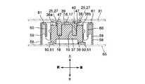
前後一対のシェル58は互いに前後対称な形状である。各シェル58は金属板(導電性材料)をプレス成形したものであり、左右方向に延びる平板状の外周側遮蔽部59を具備している。外周側遮蔽部59の内側には、外周側遮蔽部59と平行な平板からなる内周側遮蔽部60が位置している。内周側遮蔽部60の左右長は外周側遮蔽部59より短く、かつ内周側遮蔽部60の下縁部は外周側遮蔽部59の下縁部より上方に位置している。内周側遮蔽部60の上縁部と外周側遮蔽部59の上縁部を湾曲接続部61が接続している。湾曲接続部61の断面形状は上側に向かって凸の湾曲形状である(図7、図8等を参照)。
外周側遮蔽部59の左右両端部の下端にはテール片62がそれぞれ突設してある。さらに外周側遮蔽部59の左右両端には、外周側遮蔽部59に対して直交しながら内向きに延びる固定片63がそれぞれ突設してある。
前側のシェル58は、外周側遮蔽部59、内周側遮蔽部60、及び湾曲接続部61を外周壁38の前側(外周側)に位置させながら、左右の固定片63を左右のシェル取付溝45に対して上方から嵌合することによりリセプタクルインシュレータ36に対して固定してある。同様に、後側のシェル58は、外周側遮蔽部59、内周側遮蔽部60、及び湾曲接続部61を外周壁38の後側(外周側)に位置させながら、左右の固定片63を左右のシェル取付溝45に対して上方から嵌合することによりリセプタクルインシュレータ36に対して固定してある。
前後のシェル58をリセプタクルインシュレータ36に固定すると、前後の外周側遮蔽部59及び内周側遮蔽部60が外周壁38の前面と後面の外周側に位置し、さらに外周側遮蔽部59の下端部が各リセプタクルコンタクト50のテール片51と前後方向に対向する(図7、図8参照)。さらに、シェル58の湾曲接続部61および固定部63の上端部が、前壁38a、後壁38b、及びリセプタクルコンタクト50の上端部より上方に位置する(図7、図8参照)。The pair of front and
The
When the front and
以上構造のリセプタクルコネクタ35は、回路基板31と平行な板材である回路基板65(リジッド基板。第一回路基板)の実装面に形成された回路パターン(図示略)に対して各リセプタクルコンタクト50のテール片51をはんだ付けし、さらに当該実装に形成された接地パターンに対してテール片56及びテール片62をはんだ付けすることにより、回路基板65に対して固定(実装)する(図7、図8参照)。回路基板65の実装面にはリセプタクルコネクタ35とは別の電子部品(例えば、CPU、コントローラー、メモリ等)が実装してある。 The
続いてリセプタクルコネクタ35に対してプラグコネクタ15を接続する要領について説明する。
まずは図1、図2に示すように、プラグコネクタ15とリセプタクルコネクタ35を互いの前後位置及び左右位置を一致させながら上下方向に対向させる。そしてプラグコネクタ15を下方に移動させて、プラグコネクタ15の下端部をリセプタクルインシュレータ36の上端部に対して接触させる。するとリセプタクルインシュレータ36の各誘い込み面47に対してプラグインシュレータ16の各誘い込み面22がそれぞれ接触することにより、プラグインシュレータ16がリセプタクルインシュレータ36に対して下方に移動案内される。そして、嵌合凸部18が嵌合凹部40に嵌合し、係合凹部19が係合凸部39に嵌合する(図7、図8参照)。さらに各プラグコンタクト25の接触片26が対応するリセプタクルコンタクト50の弾性接触片53を弾性変形させながら弾性接触片53に対してそれぞれ接触するので、プラグコンタクト25及びリセプタクルコンタクト50を介して回路基板31と回路基板65が電気的に導通可能になる。またプラグコネクタ15の左右の接続用凹部24に対して、リセプタクルインシュレータ36の左右の接続用突起46が嵌合する。
なお、プラグコネクタ15とリセプタクルコネクタ35の左右位置が僅かにずれた状態で、プラグコネクタ15を下方に移動させてリセプタクルコネクタ35に対して接続しようとしたときに、プラグインシュレータ16の嵌合凸部18の前壁又は後壁が前側のシェル58の湾曲接続部61又は後側のシェル58の湾曲接続部61に接触することがある。しかし、前後いずれかの湾曲接続部61に接触した嵌合凸部18の前壁又は後壁(プラグコネクタ15)が当該湾曲接続部61によって内側(リセプタクルインシュレータ36)に移動案内されるので、この場合もプラグコネクタ15とリセプタクルコネクタ35を容易に接続させることが可能である。さらに、湾曲接続部61は湾曲しているので、プラグインシュレータ16の嵌合凸部18の前壁又は後壁を傷つけたり破損させたりするおそれが少ない。
また外周側遮蔽部59と内周側遮蔽部60を湾曲接続部61によって接続することによりシェル58の機械的強度を向上させているので、プラグインシュレータ16の嵌合凸部18の前壁や後壁がシェル58の湾曲接続部61(又は外周側遮蔽部59や内周側遮蔽部60)に接触しても、シェル58が破損するおそれは小さい。
さらに、静電気に帯電している作業者が手や治具でプラグコネクタ15を把持しながらリセプタクルコネクタ35に対して接続させることがある。このとき、プラグコネクタ15をリセプタクルコネクタ35に近づけると、静電気はリセプタクルコンタクト50より上方に位置する湾曲接続部61や固定片63の上端部などに落ちるため、シェル58を介して回路基板65の接地パターンに流れる(逃げる)ことになる。これにより回路基板65に実装されている電子部品を静電気から保護できる。Next, a procedure for connecting the
First, as shown in FIGS. 1 and 2, the
Note that when the
Further, since the mechanical strength of the
Further, an operator charged with static electricity may be connected to the
そしてリセプタクルインシュレータ36の外周側(前方及び後方)から外周壁38の前壁38a及び後壁38bと対向する前後のシェル58の外周側遮蔽部59及び内周側遮蔽部60が、各プラグコンタクト25及び各リセプタクルコンタクト50の外周側(前方及び後方)に位置する。さらに前後のシェル58の外周側遮蔽部59の下部が各リセプタクルコンタクト50のテール片51と前後方向に対向する。そのため、前後のシェル58によって、各リセプタクルコンタクト50(テール片51を含む)に外部ノイズが入ったり、各リセプタクルコンタクト50(テール片51を含む)のノイズが外部に漏れるのを効果的に防止できる。さらにシェル58は、湾曲接続部61および固定部63の上端部が、前壁38a、後壁38b、及びリセプタクルコンタクト50の上端部より上方に位置するので、プラグコネクタ15が実装されている回路基板31との距離(間隙)が小さくなる。そのため、前後のシェル58によって、各プラグコンタクト25に外部ノイズが入ったり、各プラグコンタクト25のノイズが外部に漏れるのを効果的に防止できる。従って、回路基板31に実装した上記電子部品(例えば高機能用モジュールや半導体、大容量メモリー等)と回路基板65に実装した上記電子部品(例えば、CPU、コントローラー、メモリ等)の間における(大量の)情報の高速通信が可能になる。 Then, the outer peripheral
以上、本発明を上記各実施形態に基づいて説明したが、本発明は上記実施形態に限定されるものではなく、様々な変形を施しながら実施可能である。
例えばシェル58から外周側遮蔽部59と内周側遮蔽部60の一方を省略してもよい。その一方で、外周側遮蔽部59及び内周側遮蔽部60とは別の遮蔽部(一つ又は複数)を外周側遮蔽部59及び内周側遮蔽部60と前後方向に並べて設けても良い。
また、シェル58の外周側遮蔽部59または内周側遮蔽部60の下端部を回路基板65の接地パターンにはんだ付けしてもよい。
プラグコネクタ15から固定金具28を省略したり、リセプタクルコネクタ35から固定金具55を省略してもよい。
また、シェル58の基材を樹脂により構成し、当該基材(樹脂)の表面を導電性材料によりめっきやコーティングしてもよい。
また回路基板31、65をプラグコネクタ15やリセプタクルコネクタ35に対してライトアングル(RA)態様で接続してもよい。さらにリジッド基板以外の回路基板(例えば、FPC(フレキシブルプリント回路基板))をプラグコネクタ15やリセプタクルコネクタ35に接続してもよい。As mentioned above, although this invention was demonstrated based on said each embodiment, this invention is not limited to the said embodiment, It can implement, giving various deformation | transformation.
For example, one of the outer peripheral
Further, the lower end portion of the outer peripheral
The fixing
Further, the base material of the
Further, the
10 コネクタ
15 プラグコネクタ
16 プラグインシュレータ
17 天井板部
18 嵌合凸部
19 係合凹部
21 コンタクト取付溝
22 誘い込み面
23 金具取付用凹部
24 接続用凹部
25 プラグコンタクト
26 接触片
27 テール片
28 固定金具
29 テール片
31 回路基板(第二回路基板)
35 リセプタクルコネクタ
36 リセプタクルインシュレータ
37 底板部
38 外周壁
38a 前壁(コンタクト取付部)
38b 後壁(コンタクト取付部)
39 係合凸部
40 嵌合凹部
42 コンタクト取付溝
43 変形許容溝
44 金具取付溝
45 シェル取付溝
46 接続用突起
47 誘い込み面
50 リセプタクルコンタクト
51 テール片
52 固定片
53 弾性接触片
55 固定金具
56 テール片
58 シェル(導電性部材)
59 外周側遮蔽部
60 内周側遮蔽部
61 湾曲接続部
62 テール片
63 固定片
65 回路基板(第一回路基板)
DESCRIPTION OF
35
38b Rear wall (contact mounting part)
39 Engaging
59 Outer peripheral
Claims (2)
Translated fromJapanese第一回路基板の上記実装面に実装可能なテール片と、上記嵌合凹部内に位置する接触片と、を備える、該リセプタクルインシュレータに支持した複数のリセプタクルコンタクト、及び
上記リセプタクルインシュレータに支持した導電性部材
を具備するリセプタクルコネクタと、
上記嵌合凹部に嵌合可能な環状の嵌合凸部を有するプラグインシュレータ、及び
該プラグインシュレータに支持した、一端を第二回路基板の上記実装面に実装し、かつ上記嵌合凸部が上記嵌合凹部に嵌合したときに一部が上記接触片と接触する複数のプラグコンタクト、
を具備するプラグコネクタと、
を備えるコネクタにおいて、
上記リセプタクルコンタクトの上記テール片が上記外周壁の外周側に位置し、
上記導電性部材が、上記リセプタクルインシュレータの外周側から上記外周壁及び上記テール片と対向する遮蔽部を有し、
上記遮蔽部が、外周側遮蔽部と、該外周側遮蔽部と上記外周壁の間に位置する内周側遮蔽部と、上記外周側遮蔽部と上記内周側遮蔽部の上記一方向側の端部どうしを接続し、かつ断面形状が上記一方向側に凸の湾曲形状である湾曲接続部と、を備えることを特徴とするコネクタ。A receptacle insulator having an annular outer peripheral wall projecting in one direction and a fitting recess formed inside the outer peripheral wall;
A plurality of receptacle contacts supported by the receptacle insulator, and a conductive piece supported by the receptacle insulator, the tail piece being mountable on the mounting surface of the first circuit board; and a contact piece positioned in the fitting recess. A receptacle connector comprising a conductive member;
A plug insulator having an annular fitting convex portion that can be fitted in the fitting concave portion, and one end supported by the plug insulator mounted on the mounting surface of the second circuit board, and the fitting convex portion is A plurality of plug contacts, part of which comes into contact with the contact piece when fitted into the fitting recess,
A plug connector comprising:
In a connector comprising:
The tail piece of the receptacle contact is located on the outer peripheral side of the outer peripheral wall;
The conductive member,have a blocking portion opposed to the outer peripheral wall and the tail piece from the outer side of the receptacleinsulator,
The shielding portion includes an outer peripheral side shielding portion, an inner peripheral side shielding portion located between the outer peripheral side shielding portion and the outer peripheral wall, and the one-direction side of the outer peripheral side shielding portion and the inner peripheral side shielding portion. A connector comprising:a curved connecting portion that connects end portions and has a curved shape in which the cross-sectional shape is convex toward theone-direction side .
上記外周壁が、上記リセプタクルコンタクトを取り付けたコンタクト取付部を有し、
該コンタクト取付部及び上記リセプタクルコンタクトの上記一方向側の端部よりも、上記湾曲接続部が上記一方向側に位置するコネクタ。The connector according to claim1 , wherein
The outer peripheral wall has a contact mounting portion to which the receptacle contact is mounted;
The connector in which the curved connecting portion is located on the one-direction side with respect to the end portion on the one-direction side of the contact mounting portion and the receptacle contact.
Priority Applications (2)
| Application Number | Priority Date | Filing Date | Title |
|---|---|---|---|
| JP2013068465AJP6045953B2 (en) | 2013-03-28 | 2013-03-28 | connector |
| KR1020130095765AKR101473266B1 (en) | 2013-03-28 | 2013-08-13 | Connector |
Applications Claiming Priority (1)
| Application Number | Priority Date | Filing Date | Title |
|---|---|---|---|
| JP2013068465AJP6045953B2 (en) | 2013-03-28 | 2013-03-28 | connector |
Publications (2)
| Publication Number | Publication Date |
|---|---|
| JP2014192102A JP2014192102A (en) | 2014-10-06 |
| JP6045953B2true JP6045953B2 (en) | 2016-12-14 |
Family
ID=51838156
Family Applications (1)
| Application Number | Title | Priority Date | Filing Date |
|---|---|---|---|
| JP2013068465AActiveJP6045953B2 (en) | 2013-03-28 | 2013-03-28 | connector |
Country Status (2)
| Country | Link |
|---|---|
| JP (1) | JP6045953B2 (en) |
| KR (1) | KR101473266B1 (en) |
Families Citing this family (7)
| Publication number | Priority date | Publication date | Assignee | Title |
|---|---|---|---|---|
| JP6256426B2 (en) | 2015-07-29 | 2018-01-10 | 第一精工株式会社 | Electrical connector for board connection |
| JP6281539B2 (en)* | 2015-07-29 | 2018-02-21 | 第一精工株式会社 | Electric connector device for board connection |
| US10084265B2 (en) | 2015-07-29 | 2018-09-25 | Dai-Ichi Seiko Co., Ltd. | Board-connecting electric connector device |
| JP6179564B2 (en)* | 2015-07-29 | 2017-08-16 | 第一精工株式会社 | Electrical connector for board connection |
| JP6628685B2 (en)* | 2016-05-16 | 2020-01-15 | ヒロセ電機株式会社 | Connector assembly having plug connector and receptacle connector |
| WO2020255700A1 (en)* | 2019-06-20 | 2020-12-24 | 株式会社村田製作所 | Multi-pole connector and multi-pole connector set |
| JP7244412B2 (en)* | 2019-12-25 | 2023-03-22 | 京セラ株式会社 | Connectors and electronics |
Family Cites Families (1)
| Publication number | Priority date | Publication date | Assignee | Title |
|---|---|---|---|---|
| JP5405640B1 (en)* | 2012-10-05 | 2014-02-05 | 日本航空電子工業株式会社 | connector |
- 2013
- 2013-03-28JPJP2013068465Apatent/JP6045953B2/enactiveActive
- 2013-08-13KRKR1020130095765Apatent/KR101473266B1/enactiveActive
Also Published As
| Publication number | Publication date |
|---|---|
| KR101473266B1 (en) | 2014-12-16 |
| KR20140119612A (en) | 2014-10-10 |
| JP2014192102A (en) | 2014-10-06 |
Similar Documents
| Publication | Publication Date | Title |
|---|---|---|
| JP6045953B2 (en) | connector | |
| US10601182B2 (en) | Connector | |
| US10777941B2 (en) | Connector | |
| US10985499B2 (en) | Electric connector | |
| EP3764483B1 (en) | Connector and electronic device | |
| US10381776B2 (en) | Connector assembly with an improved latch member having a shorter length | |
| KR102165751B1 (en) | Contact | |
| KR101862009B1 (en) | FFC/FPC for high speed signal transmission | |
| JP2010282964A (en) | Connector device | |
| JP2015099694A (en) | Receptacle connector and method of manufacturing receptacle connector | |
| US20190020133A1 (en) | Plug connector | |
| TWI746721B (en) | Electrical connector and assembly | |
| JP6401705B2 (en) | connector | |
| JP6266734B1 (en) | connector | |
| JP2021064471A (en) | Connector and connector assembly | |
| JP2016038937A (en) | connector | |
| US9899756B2 (en) | Connector and connector structure | |
| US20130273754A1 (en) | Connector | |
| JP2021064470A (en) | Connector and connector assembly | |
| KR20180114416A (en) | Clip connector | |
| JP6150854B2 (en) | Receptacle connector | |
| TW201345056A (en) | Electrical connector | |
| US20150194766A1 (en) | Electrical connector having elastic element |
Legal Events
| Date | Code | Title | Description |
|---|---|---|---|
| RD04 | Notification of resignation of power of attorney | Free format text:JAPANESE INTERMEDIATE CODE: A7424 Effective date:20150130 | |
| A621 | Written request for application examination | Free format text:JAPANESE INTERMEDIATE CODE: A621 Effective date:20160208 | |
| RD03 | Notification of appointment of power of attorney | Free format text:JAPANESE INTERMEDIATE CODE: A7423 Effective date:20160302 | |
| RD04 | Notification of resignation of power of attorney | Free format text:JAPANESE INTERMEDIATE CODE: A7424 Effective date:20160331 | |
| A977 | Report on retrieval | Free format text:JAPANESE INTERMEDIATE CODE: A971007 Effective date:20161013 | |
| A131 | Notification of reasons for refusal | Free format text:JAPANESE INTERMEDIATE CODE: A131 Effective date:20161018 | |
| A521 | Written amendment | Free format text:JAPANESE INTERMEDIATE CODE: A523 Effective date:20161021 | |
| TRDD | Decision of grant or rejection written | ||
| A01 | Written decision to grant a patent or to grant a registration (utility model) | Free format text:JAPANESE INTERMEDIATE CODE: A01 Effective date:20161115 | |
| A61 | First payment of annual fees (during grant procedure) | Free format text:JAPANESE INTERMEDIATE CODE: A61 Effective date:20161116 | |
| R150 | Certificate of patent or registration of utility model | Ref document number:6045953 Country of ref document:JP Free format text:JAPANESE INTERMEDIATE CODE: R150 | |
| S111 | Request for change of ownership or part of ownership | Free format text:JAPANESE INTERMEDIATE CODE: R313111 | |
| R350 | Written notification of registration of transfer | Free format text:JAPANESE INTERMEDIATE CODE: R350 |