JP6045869B2 - Substrate processing apparatus and substrate processing method - Google Patents
Substrate processing apparatus and substrate processing methodDownload PDFInfo
- Publication number
- JP6045869B2 JP6045869B2JP2012219502AJP2012219502AJP6045869B2JP 6045869 B2JP6045869 B2JP 6045869B2JP 2012219502 AJP2012219502 AJP 2012219502AJP 2012219502 AJP2012219502 AJP 2012219502AJP 6045869 B2JP6045869 B2JP 6045869B2
- Authority
- JP
- Japan
- Prior art keywords
- substrate
- transfer robot
- transfer
- unit
- surface cleaning
- Prior art date
- Legal status (The legal status is an assumption and is not a legal conclusion. Google has not performed a legal analysis and makes no representation as to the accuracy of the status listed.)
- Active
Links
- 239000000758substrateSubstances0.000titleclaimsdescription525
- 238000012545processingMethods0.000titleclaimsdescription198
- 238000003672processing methodMethods0.000titleclaimsdescription12
- 238000012546transferMethods0.000claimsdescription341
- 238000004140cleaningMethods0.000claimsdescription167
- 230000032258transportEffects0.000claimsdescription95
- 230000007246mechanismEffects0.000claimsdescription49
- 239000004065semiconductorSubstances0.000claimsdescription14
- 230000003028elevating effectEffects0.000claimsdescription2
- 238000000034methodMethods0.000description35
- 230000008569processEffects0.000description31
- 238000010586diagramMethods0.000description7
- 239000007788liquidSubstances0.000description6
- 238000011161developmentMethods0.000description3
- 238000005192partitionMethods0.000description3
- 230000008859changeEffects0.000description2
- 230000000694effectsEffects0.000description2
- 238000005530etchingMethods0.000description2
- 230000006870functionEffects0.000description2
- 239000004973liquid crystal related substanceSubstances0.000description2
- 239000002245particleSubstances0.000description2
- XLYOFNOQVPJJNP-UHFFFAOYSA-NwaterSubstancesOXLYOFNOQVPJJNP-UHFFFAOYSA-N0.000description2
- 230000015572biosynthetic processEffects0.000description1
- 239000011248coating agentSubstances0.000description1
- 238000000576coating methodMethods0.000description1
- 239000011521glassSubstances0.000description1
- 238000010438heat treatmentMethods0.000description1
- 238000009434installationMethods0.000description1
- 238000009413insulationMethods0.000description1
- 230000010354integrationEffects0.000description1
- 239000011229interlayerSubstances0.000description1
- 230000004048modificationEffects0.000description1
- 238000012986modificationMethods0.000description1
- 238000005201scrubbingMethods0.000description1
- 238000004904shorteningMethods0.000description1
- 238000000638solvent extractionMethods0.000description1
Images


Classifications
- B—PERFORMING OPERATIONS; TRANSPORTING
- B65—CONVEYING; PACKING; STORING; HANDLING THIN OR FILAMENTARY MATERIAL
- B65G—TRANSPORT OR STORAGE DEVICES, e.g. CONVEYORS FOR LOADING OR TIPPING, SHOP CONVEYOR SYSTEMS OR PNEUMATIC TUBE CONVEYORS
- B65G49/00—Conveying systems characterised by their application for specified purposes not otherwise provided for
- H—ELECTRICITY
- H01—ELECTRIC ELEMENTS
- H01L—SEMICONDUCTOR DEVICES NOT COVERED BY CLASS H10
- H01L21/00—Processes or apparatus adapted for the manufacture or treatment of semiconductor or solid state devices or of parts thereof
- H01L21/67—Apparatus specially adapted for handling semiconductor or electric solid state devices during manufacture or treatment thereof; Apparatus specially adapted for handling wafers during manufacture or treatment of semiconductor or electric solid state devices or components ; Apparatus not specifically provided for elsewhere
- H01L21/67005—Apparatus not specifically provided for elsewhere
- H01L21/67011—Apparatus for manufacture or treatment
- H01L21/67155—Apparatus for manufacturing or treating in a plurality of work-stations
- H01L21/67201—Apparatus for manufacturing or treating in a plurality of work-stations characterized by the construction of the load-lock chamber
- H—ELECTRICITY
- H01—ELECTRIC ELEMENTS
- H01L—SEMICONDUCTOR DEVICES NOT COVERED BY CLASS H10
- H01L21/00—Processes or apparatus adapted for the manufacture or treatment of semiconductor or solid state devices or of parts thereof
- H01L21/67—Apparatus specially adapted for handling semiconductor or electric solid state devices during manufacture or treatment thereof; Apparatus specially adapted for handling wafers during manufacture or treatment of semiconductor or electric solid state devices or components ; Apparatus not specifically provided for elsewhere
- H01L21/677—Apparatus specially adapted for handling semiconductor or electric solid state devices during manufacture or treatment thereof; Apparatus specially adapted for handling wafers during manufacture or treatment of semiconductor or electric solid state devices or components ; Apparatus not specifically provided for elsewhere for conveying, e.g. between different workstations
- H01L21/67739—Apparatus specially adapted for handling semiconductor or electric solid state devices during manufacture or treatment thereof; Apparatus specially adapted for handling wafers during manufacture or treatment of semiconductor or electric solid state devices or components ; Apparatus not specifically provided for elsewhere for conveying, e.g. between different workstations into and out of processing chamber
- H01L21/67742—Mechanical parts of transfer devices
- H—ELECTRICITY
- H01—ELECTRIC ELEMENTS
- H01L—SEMICONDUCTOR DEVICES NOT COVERED BY CLASS H10
- H01L21/00—Processes or apparatus adapted for the manufacture or treatment of semiconductor or solid state devices or of parts thereof
- H01L21/67—Apparatus specially adapted for handling semiconductor or electric solid state devices during manufacture or treatment thereof; Apparatus specially adapted for handling wafers during manufacture or treatment of semiconductor or electric solid state devices or components ; Apparatus not specifically provided for elsewhere
- H01L21/677—Apparatus specially adapted for handling semiconductor or electric solid state devices during manufacture or treatment thereof; Apparatus specially adapted for handling wafers during manufacture or treatment of semiconductor or electric solid state devices or components ; Apparatus not specifically provided for elsewhere for conveying, e.g. between different workstations
- H01L21/67763—Apparatus specially adapted for handling semiconductor or electric solid state devices during manufacture or treatment thereof; Apparatus specially adapted for handling wafers during manufacture or treatment of semiconductor or electric solid state devices or components ; Apparatus not specifically provided for elsewhere for conveying, e.g. between different workstations the wafers being stored in a carrier, involving loading and unloading
- H01L21/67766—Mechanical parts of transfer devices
- H—ELECTRICITY
- H01—ELECTRIC ELEMENTS
- H01L—SEMICONDUCTOR DEVICES NOT COVERED BY CLASS H10
- H01L21/00—Processes or apparatus adapted for the manufacture or treatment of semiconductor or solid state devices or of parts thereof
- H01L21/67—Apparatus specially adapted for handling semiconductor or electric solid state devices during manufacture or treatment thereof; Apparatus specially adapted for handling wafers during manufacture or treatment of semiconductor or electric solid state devices or components ; Apparatus not specifically provided for elsewhere
- H01L21/677—Apparatus specially adapted for handling semiconductor or electric solid state devices during manufacture or treatment thereof; Apparatus specially adapted for handling wafers during manufacture or treatment of semiconductor or electric solid state devices or components ; Apparatus not specifically provided for elsewhere for conveying, e.g. between different workstations
- H01L21/67763—Apparatus specially adapted for handling semiconductor or electric solid state devices during manufacture or treatment thereof; Apparatus specially adapted for handling wafers during manufacture or treatment of semiconductor or electric solid state devices or components ; Apparatus not specifically provided for elsewhere for conveying, e.g. between different workstations the wafers being stored in a carrier, involving loading and unloading
- H01L21/67778—Apparatus specially adapted for handling semiconductor or electric solid state devices during manufacture or treatment thereof; Apparatus specially adapted for handling wafers during manufacture or treatment of semiconductor or electric solid state devices or components ; Apparatus not specifically provided for elsewhere for conveying, e.g. between different workstations the wafers being stored in a carrier, involving loading and unloading involving loading and unloading of wafers
- H01L21/67781—Batch transfer of wafers
- H—ELECTRICITY
- H01—ELECTRIC ELEMENTS
- H01L—SEMICONDUCTOR DEVICES NOT COVERED BY CLASS H10
- H01L21/00—Processes or apparatus adapted for the manufacture or treatment of semiconductor or solid state devices or of parts thereof
- H01L21/67—Apparatus specially adapted for handling semiconductor or electric solid state devices during manufacture or treatment thereof; Apparatus specially adapted for handling wafers during manufacture or treatment of semiconductor or electric solid state devices or components ; Apparatus not specifically provided for elsewhere
- H01L21/677—Apparatus specially adapted for handling semiconductor or electric solid state devices during manufacture or treatment thereof; Apparatus specially adapted for handling wafers during manufacture or treatment of semiconductor or electric solid state devices or components ; Apparatus not specifically provided for elsewhere for conveying, e.g. between different workstations
- H01L21/67796—Apparatus specially adapted for handling semiconductor or electric solid state devices during manufacture or treatment thereof; Apparatus specially adapted for handling wafers during manufacture or treatment of semiconductor or electric solid state devices or components ; Apparatus not specifically provided for elsewhere for conveying, e.g. between different workstations with angular orientation of workpieces
- H—ELECTRICITY
- H01—ELECTRIC ELEMENTS
- H01L—SEMICONDUCTOR DEVICES NOT COVERED BY CLASS H10
- H01L21/00—Processes or apparatus adapted for the manufacture or treatment of semiconductor or solid state devices or of parts thereof
- H01L21/67—Apparatus specially adapted for handling semiconductor or electric solid state devices during manufacture or treatment thereof; Apparatus specially adapted for handling wafers during manufacture or treatment of semiconductor or electric solid state devices or components ; Apparatus not specifically provided for elsewhere
- H01L21/683—Apparatus specially adapted for handling semiconductor or electric solid state devices during manufacture or treatment thereof; Apparatus specially adapted for handling wafers during manufacture or treatment of semiconductor or electric solid state devices or components ; Apparatus not specifically provided for elsewhere for supporting or gripping
- H01L21/687—Apparatus specially adapted for handling semiconductor or electric solid state devices during manufacture or treatment thereof; Apparatus specially adapted for handling wafers during manufacture or treatment of semiconductor or electric solid state devices or components ; Apparatus not specifically provided for elsewhere for supporting or gripping using mechanical means, e.g. chucks, clamps or pinches
- H01L21/68707—Apparatus specially adapted for handling semiconductor or electric solid state devices during manufacture or treatment thereof; Apparatus specially adapted for handling wafers during manufacture or treatment of semiconductor or electric solid state devices or components ; Apparatus not specifically provided for elsewhere for supporting or gripping using mechanical means, e.g. chucks, clamps or pinches the wafers being placed on a robot blade, or gripped by a gripper for conveyance
- Y—GENERAL TAGGING OF NEW TECHNOLOGICAL DEVELOPMENTS; GENERAL TAGGING OF CROSS-SECTIONAL TECHNOLOGIES SPANNING OVER SEVERAL SECTIONS OF THE IPC; TECHNICAL SUBJECTS COVERED BY FORMER USPC CROSS-REFERENCE ART COLLECTIONS [XRACs] AND DIGESTS
- Y10—TECHNICAL SUBJECTS COVERED BY FORMER USPC
- Y10S—TECHNICAL SUBJECTS COVERED BY FORMER USPC CROSS-REFERENCE ART COLLECTIONS [XRACs] AND DIGESTS
- Y10S414/00—Material or article handling
- Y10S414/135—Associated with semiconductor wafer handling
- Y10S414/137—Associated with semiconductor wafer handling including means for charging or discharging wafer cassette
Landscapes
- Engineering & Computer Science (AREA)
- Physics & Mathematics (AREA)
- Condensed Matter Physics & Semiconductors (AREA)
- General Physics & Mathematics (AREA)
- Manufacturing & Machinery (AREA)
- Computer Hardware Design (AREA)
- Microelectronics & Electronic Packaging (AREA)
- Power Engineering (AREA)
- Robotics (AREA)
- Container, Conveyance, Adherence, Positioning, Of Wafer (AREA)
- Cleaning Or Drying Semiconductors (AREA)
Description
Translated fromJapanese本発明は、半導体ウェハー、液晶表示装置用ガラス基板または太陽電池用基板等の薄板状の精密電子基板(以下、単に「基板」と称する)を順次に搬送して洗浄処理等を行う基板処理装置に関する。 The present invention relates to a substrate processing apparatus that sequentially transports a thin plate-like precision electronic substrate (hereinafter simply referred to as “substrate”) such as a semiconductor wafer, a glass substrate for a liquid crystal display device, or a substrate for a solar cell to perform a cleaning process or the like. About.
周知のように、半導体や液晶ディスプレイなどの製品は、上記基板に対して洗浄、レジスト塗布、露光、現像、エッチング、層間絶縁膜の形成、熱処理、ダイシングなどの一連の諸処理を施すことにより製造されている。基板の洗浄処理の一つとして、回転する基板の主面にブラシを当接または近接させて付着物を機械的に除去するスクラブ洗浄処理が知られている。特許文献1には、このようなスクラブ洗浄処理を行う基板処理装置が開示されている。 As is well known, products such as semiconductors and liquid crystal displays are manufactured by performing a series of processes such as cleaning, resist coating, exposure, development, etching, interlayer insulation film formation, heat treatment, and dicing on the substrate. Has been. As one of the substrate cleaning processes, a scrub cleaning process is known in which a brush is brought into contact with or close to a main surface of a rotating substrate to mechanically remove deposits.
特許文献1に開示の基板処理装置においては、未処理の基板および処理済み基板を集積するインデクサブロックと、基板にスクラブ洗浄処理を行う処理ブロックとを並設している。一般に、スクラブ洗浄処理は基板の表面のみならず裏面に対しても行われるものであり、特許文献1の処理ブロックにも表面洗浄ユニットと裏面洗浄ユニットとが搭載されている。裏面洗浄ユニットでは、基板の裏面を上に向けて処理を行う。このため、裏面洗浄を行う基板処理装置では、基板の表裏を反転させる機構が必要となる。 In the substrate processing apparatus disclosed in
特許文献1に開示の基板処理装置においては、基板を反転させる反転ユニットを、インデクサブロックと処理ブロックとの接続部分に基板受渡部として設けている。すなわち、インデクサブロックと処理ブロックとの間の基板の受け渡しのために介在する基板受渡部に反転ユニットの機能を兼ね備えているのである。このため、特許文献1の装置では搬送工程を減らすことができ、基板処理のスループットを向上させることができる。 In the substrate processing apparatus disclosed in
しかしながら、特許文献1を含む従来においては、基板を表裏反転させる反転ユニットを設け、これによって基板を180°反転させるという工程が必須であったため、そのための時間が必ず必要であった。このため、裏面洗浄処理ユニットに基板を搬入するまでに要する時間の短縮には限界があった。特に、今後の展開が検討されているφ450mmの大径の半導体ウェハーの場合、180°反転させるのに従来(φ300mm以下)よりも長時間を要するため、スループットが低下するおそれもある。 However, in the prior art including
また、大径の半導体ウェハーを反転させるための反転ユニットは、相応の大きなサイズとなるため、基板処理装置のサイズも大型化するという問題が生じる。 Moreover, since the reversing unit for reversing a large-diameter semiconductor wafer has a correspondingly large size, there arises a problem that the size of the substrate processing apparatus increases.
本発明は、上記課題に鑑みてなされたものであり、基板を反転させて処理部に搬送する時間をより短縮することができる基板処理装置および基板処理方法を提供することを目的とする。 The present invention has been made in view of the above problems, and an object of the present invention is to provide a substrate processing apparatus and a substrate processing method that can further reduce the time for inverting the substrate and transporting the substrate to the processing unit.
上記課題を解決するため、請求項1の発明は、基板に所定の処理を行う基板処理装置において、主搬送ロボットおよび当該主搬送ロボットによって基板が搬送される処理部を有する処理ブロックと、移載ロボットを有し、カセットから未処理の基板を取り出して前記処理ブロックに渡すとともに前記処理ブロックから処理済みの基板を受け取ってカセットに収納するインデクサブロックと、前記インデクサブロックと前記処理ブロックとの接続部分に設けられ、前記主搬送ロボットと前記移載ロボットとの間で受け渡される基板を起立姿勢にて保持する受渡部と、を備え、前記主搬送ロボットは、基板を把持する第1ハンドおよび前記第1ハンドを水平方向に沿う軸を中心として少なくとも90°回転させる第1回転機構を有し、前記第1ハンドに把持した基板を水平方向に沿う軸を中心として90°回転させつつ前記受渡部と前記処理部との間で当該基板を搬送し、前記移載ロボットは、基板を把持する第2ハンドおよび前記第2ハンドを水平方向に沿う軸を中心として少なくとも90°回転させる第2回転機構を有し、前記第2ハンドに把持した基板を水平方向に沿う軸を中心として90°回転させつつ前記受渡部とカセットとの間で当該基板を搬送し、前記処理部は、基板の裏面を洗浄する裏面洗浄処理ユニットを含み、前記移載ロボットが前記カセットから受け取った基板を90°回転させて前記受渡部に渡し、かつ、前記主搬送ロボットが前記受渡部から受け取った当該基板を90°回転させて前記裏面洗浄処理ユニットに渡すことによって、当該基板を表裏反転させて前記裏面洗浄処理ユニットに搬送することを特徴とする。In order to solve the above-described problems, a first aspect of the present invention is a substrate processing apparatus for performing predetermined processing on a substrate, a main transport robot, a processing block having a processing section on which a substrate is transported by the main transport robot, and transfer An indexer block which has a robot, takes out an unprocessed substrate from a cassette and passes it to the processing block and receives the processed substrate from the processing block and stores it in the cassette; and a connecting portion between the indexer block and the processing block A transfer unit that holds the substrate transferred between the main transfer robot and the transfer robot in an upright posture, and the main transfer robot includes a first hand that holds the substrate and the transfer unit A first rotating mechanism for rotating the first hand by at least 90 ° about an axis along the horizontal direction; The substrate gripped by the robot is transported between the delivery unit and the processing unit while rotating the substrate 90 degrees around an axis along the horizontal direction, and the transfer robot includes a second hand for gripping the substrate, A second rotation mechanism for rotating the second hand by at least 90 ° about an axis along a horizontal direction, and the substrate held by the second hand is rotated by 90 ° about an axis along a horizontal direction; The substrate is transported between the transferunit and the cassette, and theprocessing unit includes a back surface cleaning unit for cleaning the back surface of the substrate, and the transfer robot rotates the substrate received from the cassette by 90 ° to receive the substrate. By passing the substrate to the backside cleaning processing unit by rotating the substrate received by the main transfer robot from the delivery unit by 90 ° and passing it to the back surface cleaning processing unit, Characterized by conveying the surface cleaning processing unit.
また、請求項2の発明は、請求項1の発明に係る基板処理装置において、前記処理部は、基板の表面を洗浄する表面洗浄処理ユニットを含み、前記主搬送ロボットは、前記裏面洗浄処理ユニットから取り出した基板を180°回転させつつ前記表面洗浄処理ユニットに搬送することを特徴とする。The invention of claim 2 is the substrate processing apparatus according to the invention of
また、請求項3の発明は、請求項1または請求項2の発明に係る基板処理装置において、前記主搬送ロボットは、前記第1ハンドに把持した基板を起立姿勢にして旋回動作を行うことなく鉛直方向への昇降動作を行い、前記移載ロボットは、前記第2ハンドに把持した基板を起立姿勢にして旋回動作を行うことなく鉛直方向への昇降動作を行うことを特徴とする。According to a third aspect of the present invention, there is provided the substrate processing apparatus according to the first or second aspect of the present invention,wherein the main transfer robot does not perform a turning operation with the substrate held by the first hand in an upright posture. A vertical movement is performed, and the transfer robot performs a vertical movement without performing a turning movement with the substrate held by the second hand in an upright posture .
また、請求項4の発明は、請求項1から請求項3のいずれかの発明に係る基板処理装置において、前記基板は直径が450mmの半導体ウェハーであることを特徴とする。 According to a fourth aspect of the present invention, in the substrate processing apparatus according to any one of the first to third aspects of the present invention, the substrate is a semiconductor wafer having a diameter of 450 mm.
また、請求項5の発明は、基板に所定の処理を行う基板処理方法において、(a) 移載ロボットがカセットから未処理の基板を取り出し、当該基板を水平方向に沿う軸を中心として90°回転させつつ受渡部に渡す工程と、(b) 前記受渡部が前記移載ロボットから受け取った前記基板を起立姿勢にて保持する工程と、(c) 主搬送ロボットが前記受渡部から前記基板を受け取り、前記基板を水平方向に沿う軸を中心として90°回転させつつ処理部に搬送する工程と、(d) 前記主搬送ロボットが前記処理部から処理済みの基板を受け取り、前記基板を水平方向に沿う軸を中心として90°回転させつつ前記受渡部に渡す工程と、(e) 前記受渡部が前記主搬送ロボットから受け取った前記基板を起立姿勢にて保持する工程と、(f) 前記移載ロボットが前記受渡部から前記基板を受け取り、前記基板を水平方向に沿う軸を中心として90°回転させつつカセットに搬送して収納する工程と、を備え、前記処理部は、基板の裏面を洗浄する裏面洗浄処理ユニットを含み、前記工程(a)にて前記移載ロボットが前記カセットから受け取った基板を90°回転させて前記受渡部に渡し、かつ、前記工程(c)にて前記主搬送ロボットが前記受渡部から受け取った当該基板を90°回転させて前記裏面洗浄処理ユニットに渡すことによって、当該基板を表裏反転させて前記裏面洗浄処理ユニットに搬送することを特徴とする。Further, the invention of
また、請求項6の発明は、請求項5の発明に係る基板処理方法において、前記処理部は、基板の表面を洗浄する表面洗浄処理ユニットを含み、(g) 前記主搬送ロボットが前記裏面洗浄処理ユニットから取り出した基板を180°回転させつつ前記表面洗浄処理ユニットに搬送する工程をさらに備えることを特徴とする。Further, the invention of claim 6 is the substrate processing method according to the invention of
また、請求項7の発明は、請求項5または請求項6の発明に係る基板処理方法において、前記工程(a)および前記工程(f)は、前記移載ロボットが基板を起立姿勢にして旋回動作を行うことなく鉛直方向への昇降動作を行う工程を含み、前記工程(c)および前記工程(d)は、前記主搬送ロボットが基板を起立姿勢にして旋回動作を行うことなく鉛直方向への昇降動作を行う工程を含むことを特徴とする。The invention of claim 7 is the substrate processing method according to
また、請求項8の発明は、請求項5から請求項7のいずれかの発明に係る基板処理方法において、前記基板は直径が450mmの半導体ウェハーであることを特徴とする。 The invention of claim 8 is the substrate processing method according to any one of
請求項1から請求項4の発明によれば、基板を起立姿勢にて保持する受渡部を備え、主搬送ロボットが第1ハンドに把持した基板を水平方向に沿う軸を中心として90°回転させつつ受渡部と処理部との間で当該基板を搬送し、移載ロボットが第2ハンドに把持した基板を水平方向に沿う軸を中心として90°回転させつつ受渡部とカセットとの間で当該基板を搬送するため、基板を180°反転させるのに、移載ロボットおよび主搬送ロボットが90°ずつ分担するととともに、それらが基板を搬送しつつ90°回転させることとなり、基板を反転させて処理部に搬送する時間をより短縮することができる。 According to the first to fourth aspects of the present invention, the delivery unit that holds the substrate in an upright posture is provided, and the substrate held by the first hand by the main transport robot is rotated by 90 ° about the axis along the horizontal direction. The substrate is transported between the delivery unit and the processing unit while the substrate held by the transfer hand is rotated by 90 ° about the axis along the horizontal direction, and the substrate is transferred between the delivery unit and the cassette. In order to transfer the substrate, the transfer robot and the main transfer robot share 90 ° at a time in order to reverse the substrate by 180 °, and they rotate 90 ° while transferring the substrate. The time for transporting to the section can be further shortened.
特に、請求項3の発明によれば、主搬送ロボットが第1ハンドに把持した基板を起立姿勢にして旋回動作を行うことなく鉛直方向への昇降動作を行い、移載ロボットが第2ハンドに把持した基板を起立姿勢にして旋回動作を行うことなく鉛直方向への昇降動作を行うため、昇降動作時に基板に作用する空気抵抗は最小限となり、円滑に基板を昇降させることができる。In particular, according to the invention of claim3 , the substrate is held by the first hand robot in the upright posture, and is moved up and down in the vertical directionwithout performing aturning operation. Since the verticalmovement is performed in the vertical directionwithout performing theturning operation with the gripped substrate in the standing posture, the air resistance acting on the substrate during the lifting operation is minimized, and the substrate can be raised and lowered smoothly.
また、請求項5から請求項8の発明によれば、(a) 移載ロボットがカセットから未処理の基板を取り出し、当該基板を水平方向に沿う軸を中心として90°回転させつつ受渡部に渡す工程と、(b) 受渡部が移載ロボットから受け取った基板を起立姿勢にて保持する工程と、(c) 主搬送ロボットが受渡部から基板を受け取り、基板を水平方向に沿う軸を中心として90°回転させつつ処理部に搬送する工程と、(d) 主搬送ロボットが処理部から処理済みの基板を受け取り、基板を水平方向に沿う軸を中心として90°回転させつつ受渡部に渡す工程と、(e) 受渡部が主搬送ロボットから受け取った基板を起立姿勢にて保持する工程と、(f) 移載ロボットが受渡部から基板を受け取り、基板を水平方向に沿う軸を中心として90°回転させつつカセットに搬送して収納する工程と、を備えるため、基板を180°反転させるのに、移載ロボットおよび主搬送ロボットが90°ずつ分担するととともに、それらが基板を搬送しつつ90°回転させることとなり、基板を反転させて処理部に搬送する時間をより短縮することができる。 According to the inventions of
特に、請求項7の発明によれば、移載ロボットが基板を起立姿勢にして旋回動作を行うことなく鉛直方向への昇降動作を行い、主搬送ロボットが基板を起立姿勢にして旋回動作を行うことなく鉛直方向への昇降動作を行うため、昇降動作時に基板に作用する空気抵抗は最小限となり、円滑に基板を昇降させることができる。In particular, according to theseventh aspect of the invention, the transfer robot moves up and down in the vertical directionwithout performing aturning operation with the substrate in a standing posture, and the main transfer robotperforms aturning operation with the substrate in a standing posture.Therefore, the air resistance acting on the substrate during the lifting operation is minimized, and the substrate can be raised and lowered smoothly.
以下、図面を参照しつつ本発明の実施の形態について詳細に説明する。なお、図1および以降の各図においては、理解容易のため、必要に応じて各部の寸法や数を誇張または簡略化して描いている。 Hereinafter, embodiments of the present invention will be described in detail with reference to the drawings. In FIG. 1 and the subsequent drawings, the size and number of each part are exaggerated or simplified as necessary for easy understanding.
<1.第1実施形態>
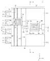
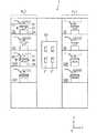
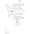
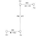
図1は、本発明に係る基板処理装置1の平面図である。また、図2は図1のA−A線から見た図であり、図3は図1のB−B線から見た図である。なお、図1から図3にはそれらの方向関係を明確にするためZ軸方向を鉛直方向とし、XY平面を水平面とするXYZ直交座標系を付している。基板処理装置1は、複数枚の基板Wに連続してスクラブ洗浄処理を行う洗浄装置であり、インデクサブロックIDおよび洗浄処理ブロックSPの2つのブロック(処理区画)を並設して構成されている。本実施形態の基板Wは円板形状の半導体ウェハーである。また、基板処理装置1は、インデクサブロックIDおよび洗浄処理ブロックSPに設けられた各動作機構を制御して基板Wの洗浄処理を実行させる制御部5を備える。<1. First Embodiment>
FIG. 1 is a plan view of a
インデクサブロックIDは、装置外から受け取った未処理の基板Wを洗浄処理ブロックSPに渡すとともに、洗浄処理ブロックSPから受け取った処理済みの基板Wを装置外に搬出するための処理区画である。インデクサブロックIDは、カセットCを載置する複数のカセットステージ11(本実施形態では4個)と、各カセットCから未処理の基板Wを取り出すとともに、各カセットCに処理済みの基板Wを収納する移載ロボットIRとを備えている。 The indexer block ID is a processing section for transferring the unprocessed substrate W received from the outside of the apparatus to the cleaning processing block SP and for carrying out the processed substrate W received from the cleaning processing block SP to the outside of the apparatus. The indexer block ID includes a plurality of cassette stages 11 (four in this embodiment) on which the cassette C is placed, and unprocessed substrates W are taken out from the cassettes C, and the processed substrates W are stored in the cassettes C. And a transfer robot IR.
各カセットステージ11に対しては、未処理の基板Wを収納したカセットCが装置外部からOHT(Overhead Hoist Transfer)等によって搬入されて載置される。また、装置内でのスクラブ洗浄処理が終了した基板Wはカセットステージ11に載置されたカセットCに再度格納される。処理済みの基板Wを格納したカセットCもOHT等によって装置外部に搬出される。すなわち、カセットステージ11は、未処理の基板Wおよび処理済みの基板Wを集積する基板集積部として機能する。なお、カセットCの形態としては、基板Wを密閉空間に収納するFOUP(front opening unified pod)の他に、SMIF(Standard Mechanical Inter Face)ポッドや収納基板Wを外気に曝すOC(open cassette)であっても良い。 On each
移載ロボットIRは、2本の移載ハンド(第2ハンド)12a,12bを備えており、これら移載ハンド12a,12bをカセットステージ11に載置されたカセットCおよび後述の基板受渡部50にアクセスさせ、カセットCと基板受渡部50との間で基板Wを搬送する。また、詳細は後述するが、移載ロボットIRは、移載ハンド12a,12bを水平方向に沿った軸を中心として回転させることができ、移載ハンド12a,12bを水平姿勢から90°回転させた状態で基板受渡部50にアクセスさせる。 The transfer robot IR includes two transfer hands (second hands) 12a and 12b. The transfer hands 12a and 12b are placed on the
インデクサブロックIDに隣接して洗浄処理ブロックSPが設けられている。インデクサブロックIDと洗浄処理ブロックSPとの間には雰囲気遮断用の隔壁19が設けられており、その隔壁19の一部を貫通して基板受渡部50が設けられている。すなわち、基板受渡部50はインデクサブロックIDと洗浄処理ブロックSPとの接続部分に設けられているものであり、両ブロック間での基板Wの受け渡しのために介在している。基板受渡部50は、2つの縦パス51,51を備えており、これについてはさらに後述する。 A cleaning processing block SP is provided adjacent to the indexer block ID. A
洗浄処理ブロックSPは、基板Wにスクラブ洗浄処理を行う処理区画であり、基板Wのスクラブ洗浄処理を行う第1処理部列PL1および第2処理部列PL2と、それらに含まれる処理部間で基板Wの搬送を行う主搬送ロボットMRと、を備える。洗浄処理ブロックSPにおいては、主搬送ロボットMRを挟んで第1処理部列PL1と第2処理部列PL2とが対向して配置されている。具体的には、第1処理部列PL1が(+Y)側に、第2処理部列PL2が(−Y)側に、それぞれ位置している。 The cleaning processing block SP is a processing section that performs a scrub cleaning process on the substrate W. Between the first processing unit row PL1 and the second processing unit row PL2 that perform the scrub cleaning process on the substrate W, and the processing units included in them. A main transfer robot MR that transfers the substrate W. In the cleaning processing block SP, the first processing section row PL1 and the second processing section row PL2 are arranged to face each other with the main transport robot MR interposed therebetween. Specifically, the first processing section row PL1 is located on the (+ Y) side, and the second processing section row PL2 is located on the (−Y) side.
図2に示すように、第1処理部列PL1および第2処理部列PL2は、それぞれスクラブ洗浄処理を行う4つの処理部を積層配置している。第1処理部列PL1は、処理部として上から順に2つの表面洗浄処理ユニットSSと2つの裏面洗浄処理ユニットSSRとを備える。同様に第2処理部列PL2も、処理部として上から順に2つの表面洗浄処理ユニットSSと2つの裏面洗浄処理ユニットSSRとを備える。 As shown in FIG. 2, each of the first processing unit row PL1 and the second processing unit row PL2 includes four processing units that perform scrub cleaning processing in a stacked manner. The first processing unit row PL1 includes two front surface cleaning processing units SS and two back surface cleaning processing units SSR in order from the top as processing units. Similarly, the second processing section row PL2 includes two front surface cleaning processing units SS and two back surface cleaning processing units SSR in order from the top as processing sections.
表面洗浄処理ユニットSSは、表面が上側を向く基板Wを水平姿勢で保持して鉛直方向に沿った軸心周りで回転させるスピンチャック21、スピンチャック21上に保持された基板Wの表面に当接または近接してスクラブ洗浄を行う洗浄ブラシ22、基板Wの表面に洗浄液(例えば純水)を吐出するノズル23、スピンチャック21を回転駆動させるスピンモータ24およびスピンチャック21上に保持された基板Wの周囲を囲繞するカップ(図示省略)等を備えている。表面洗浄処理ユニットSSは、スピンチャック21に保持した基板Wを回転させつつ、その表面にノズル23から洗浄液を供給して洗浄ブラシ22を当接または近接させることによって基板Wの表面のスクラブ洗浄処理を行う。なお、基板Wの「表面」とは基板Wの主面のうちのパターンが形成される面であり、「裏面」とは表面の反対側の面である。また、基板Wの「上面」とは基板Wの主面のうち上側を向いている面であり、「下面」とは下側を向いている面である(表面であるか裏面であるかと関わりない)。 The surface cleaning processing unit SS holds the substrate W whose surface is directed upward in a horizontal posture and rotates it around the axis center along the vertical direction, and the surface cleaning processing unit SS touches the surface of the substrate W held on the
一方、裏面洗浄処理ユニットSSRは、裏面が上側を向く基板Wを水平姿勢で保持して鉛直方向に沿った軸心周りで回転させるスピンチャック26、スピンチャック26上に保持された基板Wの裏面に当接または近接してスクラブ洗浄を行う洗浄ブラシ27、基板Wの裏面に洗浄液(例えば純水)を吐出するノズル28、スピンチャック26を回転駆動させるスピンモータ29およびスピンチャック26上に保持された基板Wの周囲を囲繞するカップ(図示省略)等を備えている。裏面洗浄処理ユニットSSRは、スピンチャック26に保持した基板Wを回転させつつ、その裏面に洗浄液を供給して洗浄ブラシ27を当接または近接させることによって基板Wの裏面のスクラブ洗浄処理を行う。なお、表面洗浄を行う表面洗浄処理ユニットSSのスピンチャック21は基板Wを裏面側から保持するため真空吸着方式のものであってもよいが、裏面洗浄を行う裏面洗浄処理ユニットSSRのスピンチャック26は基板Wの表面側から保持するため基板端縁部を機械的に把持する形式のものが好ましい。 On the other hand, the back surface cleaning processing unit SSR holds the substrate W with the back surface facing upward in a horizontal posture and rotates it around the axis along the vertical direction, and the back surface of the substrate W held on the
搬送ロボットMRは、2本の搬送ハンド(第1ハンド)32a,32bを備えており、これら搬送ハンド32a,32bを第1処理部列PL1および第2処理部列PL2に含まれる処理部および基板受渡部50にアクセスさせ、基板受渡部50と処理部との間で基板Wを搬送する。また、搬送ロボットMRは、搬送ハンド32a,32bを水平方向に沿った軸を中心として回転させることができ、搬送ハンド32a,32bを水平姿勢から90°回転させた状態で基板受渡部50にアクセスさせる。 The transfer robot MR includes two transfer hands (first hands) 32a and 32b, and these
図4および図5は、搬送ロボットMRの搬送ハンド32a,32bの構造を示す図である。図4は、搬送ハンド32a,32bを側方から見た図である。図5は、図4において矢印AR4の向きから搬送ハンド32a,32bを見た図である。また、図4(a)および図5(a)は、搬送ハンド32a,32bを水平姿勢としたときの図であり、図4(b)および図5(b)は、搬送ハンド32a,32bを水平姿勢から90°回転させたときの図である。 4 and 5 are diagrams showing the structure of the transfer hands 32a and 32b of the transfer robot MR. FIG. 4 is a view of the
回転板35には、水平方向に沿って延びるように2本のスライドアーム33a,33bが固設されている。スライドアーム33aには、搬送ハンド32aが水平方向に沿って前後に進退移動可能に取り付けられている。スライドアーム33aには、図示省略のスライド駆動機構が付設されており、それによって搬送ハンド32aが矢印AR41にて示すように前後に進退移動する。一方、スライドアーム33bには、搬送ハンド32bが水平方向に沿って前後に進退移動可能に取り付けられている。スライドアーム33bにもスライド駆動機構が付設されており、それによって搬送ハンド32bが矢印AR41に示すように前後に進退移動する。従って、搬送ハンド32a,32bは互いに独立して進退移動される。 Two
ロータリアクチュエータ(第1回転機構)36は、水平方向に沿った回転中心軸RXの周りで回転板35を回転させる。回転中心軸RXは、回転板35の中心を貫通し、搬送ハンド32a,32bの進退移動方向と平行である。また、2本のスライドアーム33a,33bは、回転中心軸RXを中心として対称となる位置に設けられている。さらに、2本の搬送ハンド32a,32bもともに進退移動の位置が同じであれば、回転中心軸RXを中心として対称となるように設けられている。よって、ロータリアクチュエータ36が回転板35を180°回転させると、搬送ハンド32a,32bの位置が互いに入れ替わることとなる。なお、回転板35の形状は、2本のスライドアーム33a,33bを支持できるものであれば良く、矩形であっても良いし、円板状であっても良い。 The rotary actuator (first rotation mechanism) 36 rotates the
図4(b)に示すように、搬送ハンド32a,32bは、ともに平面視で2本のフィンガーを有するフォーク状に形成されている。搬送ハンド32a,32bは、フォーク状部分でそれぞれ1枚の基板Wを保持する。搬送ハンド32a,32bのフォーク形状は、処理部の受け渡しピン等と干渉しない形状とされている。 As shown in FIG. 4B, the
搬送ハンド32a,32bの2本のフィンガー部分のそれぞれ先端には係止部34が設けられている。一方、2本のフィンガー部分の付け根の位置には把持機構37が設けられている。把持機構37は、把持部38を水平方向に沿って進退移動させる。把持機構37としては、エアシリンダやアクチュエータなどの公知の種々の直線駆動機構を採用することができる。搬送ハンド32a,32bのフォーク状部分に基板Wを載置し、把持機構37が把持部38を前進させると、2箇所の係止部34と把持部38とによって3点で基板Wが確実に把持されることとなる。把持機構37によって基板Wが把持された状態では、搬送ハンド32a,32bが180°回転して反転しても基板Wが落下しないように適切な把持力が維持される。また、把持機構37が把持部38を後退させると、基板Wの把持状態が解除され、搬送ハンド32a,32bに対する基板Wの受け渡しが可能となる。 A locking
また、本実施形態においては、2本のスライドアーム33a,33bの間に遮蔽板39が設けられている。この遮蔽板39は、搬送ハンド32aに保持された基板Wと搬送ハンド32bに保持された基板Wとの間でパーティクルの移動等が生じないように仕切るためのものである。 In the present embodiment, a shielding
図1および図3に戻り、2本の搬送ハンド32a,32bおよびロータリアクチュエータ36は、支持部41によって支持されている。支持部41は基台43に搭載されている。支持部41は、内蔵する回転駆動機構によって、基台43に対して水平面内で旋回する。これにより、搬送ハンド32a,32bも水平面内で旋回する。 Returning to FIGS. 1 and 3, the two
基台43は昇降駆動部45に取り付けられている。昇降駆動部45は洗浄処理ブロックSPのフレームに固定設置されている。昇降駆動部45は、直線駆動機構を内蔵しており、基台43を鉛直方向(Z軸方向)に沿って昇降させる。これにより、搬送ハンド32a,32bも鉛直方向に昇降する。 The
このような構成によって、主搬送ロボットMRは、2本の搬送ハンド32a,32bを鉛直方向に沿って昇降させるとともに、水平面内で旋回させることができる。また、主搬送ロボットMRは、2本の搬送ハンド32a,32bを水平方向に沿った回転中心軸RXの周りで一括して回転させるとともに、2本の搬送ハンド32a,32bを個別に独立して水平方向(支持部41の旋回半径方向)に沿って進退移動させる。これにより、主搬送ロボットMRは、2本の搬送ハンド32a,32bをそれぞれに個別に、第1処理部列PL1および第2処理部列PL2に含まれる処理部(表面洗浄処理ユニットSSおよび裏面洗浄処理ユニットSSR)および基板受渡部50にアクセスさせ、それらとの間で基板Wの授受を行うことができる。なお、昇降駆動部45は固定設置されているため、主搬送ロボットMRの全体は水平方向に移動は行わない。 With such a configuration, the main transfer robot MR can raise and lower the two
一方、移載ロボットIRの移載ハンド12a,12bの構造は主搬送ロボットMRの搬送ハンド32a,32bと同じである。すなわち、回転板15に固設された2本のスライドアームの一方に移載ハンド12aが取り付けられ、他方に移載ハンド12bが取り付けられている(図1および図3参照)。移載ハンド12a,12bは、スライドアームによって水平方向に沿って前後に進退移動される。主搬送ロボットMRと同様に、回転板15はロータリアクチュエータ(第2回転機構)16によって、水平方向に沿った回転中心軸の周りで回転される。 On the other hand, the structures of the transfer hands 12a and 12b of the transfer robot IR are the same as the transfer hands 32a and 32b of the main transfer robot MR. That is, the
また、移載ハンド12a,12bは、搬送ハンド32a,32bと同様の把持機構を備えており、保持する基板Wを把持することができる。このため、移載ハンド12a,12bがロータリアクチュエータ16によって回転したときにも、移載ハンド12a,12bに保持された基板Wが落下しないように適切な把持力が維持される。さらに、主搬送ロボットMRと同様に、2本のスライドアームの間には移載ハンド12aと移載ハンド12bとを仕切る遮蔽板が設けられている。 Moreover, the transfer hands 12a and 12b are provided with a holding mechanism similar to the transfer hands 32a and 32b, and can hold the substrate W to be held. For this reason, even when the transfer hands 12a and 12b are rotated by the
図1および図3に示すように、2本の移載ハンド12a,12bおよびロータリアクチュエータ16は、可動部14によって支持されている。可動部14は、カセットステージ11の並びと平行に(Y軸方向に沿って)延びるボールネジ17に螺合されるとともに、2本のガイドレール18,18に対して摺動自在に設けられている。よって、図示を省略する回転モータによってボールネジ17が回転すると、可動部14を含む移載ロボットIRの全体がY軸方向に沿って水平移動する。 As shown in FIGS. 1 and 3, the two
可動部14は、水平方向に移動可能であるとともに、それ自体は内蔵する回転駆動機構によって水平面内で旋回する。また、可動部14は、入れ子構造の複数の支持体を伸縮させる(いわゆるテレスコピック機構)ことによって鉛直方向に沿って昇降する。これにより、移載ハンド12a,12bは、水平面内で旋回するとともに、鉛直方向にも昇降する。 The
このようような構成によって、移載ロボットIRは、2本の移載ハンド12a,12bをY軸方向に沿って水平移動させ、鉛直方向に沿って昇降させるとともに、水平面内で旋回させることができる。また、移載ロボットIRは、2本の移載ハンド12a,12bを水平方向に沿った回転中心軸の周りで一括して回転させるとともに、2本の移載ハンド12a,12bを個別に独立して水平方向(可動部14の旋回半径方向)に沿って進退移動させる。これにより、移載ロボットIRは、2本の移載ハンド12a,12bをそれぞれ個別に、カセットステージ11に載置されたカセットCおよび基板受渡部50にアクセスさせ、それらとの間で基板Wの授受を行うことができる。 With such a configuration, the transfer robot IR can move the two
基板受渡部50には、2つの縦パス511,512(2つの縦パス511,512を特に区別しない場合には縦パス51と総称する)が設けられている。図6および図7は、縦パス51の構造を示す図である。図6は縦パス51をY軸方向から((−Y)側から)見た図であり、図7は縦パス51をX軸方向から((−X)側から)見た図である。縦パス51は、一対の把持体52a,52bおよび把持機構53を備える。把持体52aと把持体52bとは鉛直方向(Z軸方向)に沿って、互いに対向するように設けられている。本実施形態では、上側の把持体52aは鉛直方向には移動しないように固定されている。一方、下側の把持体52bは把持機構53によって昇降移動される。把持体52aの下端および把持体52bの上端には円形の基板Wの外周に沿うような溝が形成されている。なお、把持機構53としては、エアシリンダやアクチュエータなどの公知の種々の直線駆動機構を採用することができる。 The
2つの縦パス511,512は、スライド駆動機構54によってY軸方向に沿って移動可能である(図7)。縦パス511,512がY軸方向に移動するときには、一対の把持体52a,52bが連動して相対向する状態を維持するように移動する。スライド駆動機構54としては、エアシリンダやアクチュエータなどの公知の種々の直線駆動機構を採用することができる。なお、図7のように2つの縦パス511,512のそれぞれにスライド駆動機構54を個別に設け、2つの縦パス511,512を独立して移動させるようにしても良いし、1つのスライド駆動機構54によって一括して移動させるようにしても良い。 The two
把持機構53が下側の把持体52bを図6の一点鎖線位置に下降させているときには、上側の把持体52aと下側の把持体52bとの間に起立姿勢の基板Wを挿脱することができる。ここで、「起立姿勢」とは、基板Wの主面が鉛直方向に沿う姿勢、つまり主面の法線が水平方向に沿う姿勢である。「起立姿勢」には、基板Wの主面が完全に鉛直方向に沿う姿勢の他に、鉛直方向から若干傾斜した姿勢も含まれる。 When the
図6では、移載ロボットIRの移載ハンド12aが起立姿勢の基板Wを2つの縦パス51のうち(−Y)側の縦パス512に渡す様子を示している。移載ロボットIRの移載ハンド12aは(−X)側から(+X)側に向けて前進し、起立姿勢の基板Wを縦パス512の一対の把持体52a,52bの間に挿入する。そして、この状態にて把持機構53が下側の把持体52bを上昇させると、一対の把持体52a,52bによって起立姿勢の基板Wの端縁部が把持される。これにより、縦パス512が当該基板Wを起立姿勢のまま保持する。その後、移載ハンド12aの把持機構37が把持部38を後退させて基板Wの把持を解除し、縦パス512が(−Y)側に向けて移動する。続いて、移載ロボットIRの移載ハンド12aが(−X)側に向けて後退する。このようにして、移載ロボットIRの移載ハンド12aから縦パス512への基板Wの受け渡しが完了する。 FIG. 6 shows a state in which the
縦パス512が(−Y)側に向けて移動することにより、移載ハンド12aから縦パス512に基板Wが渡された後の、移載ハンド12aと基板Wとの干渉を防止することができる。また、移載ハンド12aが(−X)側に向けて後退した後も、起立姿勢の基板Wが縦パス512の一対の把持体52a,52bによって安定して把持されているため、基板Wの落下または転倒を防止することができる。図6では、一例として移載ロボットIRの移載ハンド12aが基板Wを基板受渡部50に受け渡しする様子を示したが、移載ハンド12bについても同様にして基板Wの受け渡しが可能となっている。なお、図6に示すように、移載ロボットIRの移載ハンド12a,12bおよび主搬送ロボットMRの搬送ハンド32a,32bは、一対の把持体52a,52bと干渉しない形状とされている。 By moving the
上述のようにして、移載ロボットIRから基板受渡部50に渡された基板Wを主搬送ロボットMRが受け取るときには、縦パス512に基板Wが起立姿勢にて保持されている状態で、主搬送ロボットMRの搬送ハンド32aが基板Wに対向する位置にまで(+X)側から(−X)側に向けて前進する。そして、縦パス512がY軸方向に移動して搬送ハンド32aが基板Wを把持した後、把持機構53が下側の把持体52bを下降させて基板Wの把持を解除する。その後、基板Wを把持した搬送ハンド32aが後退して基板受渡部50から主搬送ロボットMRに基板Wが渡される。なお、主搬送ロボットMRの搬送ハンド32bについても同様にて基板Wの受け渡しが可能となっている。 As described above, when the main transfer robot MR receives the substrate W transferred from the transfer robot IR to the
また、ここでは、移載ロボットIRから基板受渡部50を介して主搬送ロボットMRに基板Wを渡す例を説明したが、移載ロボットIRの移載ハンド12a,12bと主搬送ロボットMRの搬送ハンド32a,32bとは同様の構造を有しており、主搬送ロボットMRから基板受渡部50を介して移載ロボットIRに基板Wを渡す場合も全く同様にして基板Wが受け渡される。このように、基板受渡部50は、移載ロボットIRと主搬送ロボットMRとの間で受け渡される基板Wを起立姿勢にて保持する。 Here, an example has been described in which the substrate W is transferred from the transfer robot IR to the main transfer robot MR via the
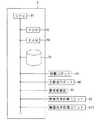
また、制御部5は、基板処理装置1に設けられた種々の動作機構を制御する。図8は、制御部5の制御ブロック図である。制御部5のハードウェアとしての構成は一般的なコンピュータと同様である。すなわち、制御部5は、各種演算処理を行うCPU91、基本プログラムを記憶する読み出し専用のメモリであるROM92、各種情報を記憶する読み書き自在のメモリであるRAM93および制御用ソフトウェアやデータなどを記憶しておく磁気ディスク94を備えている。また、制御部5は、基板処理装置1に設けられた移載ロボットIR、主搬送ロボットMR、基板受渡部50、表面洗浄処理ユニットSSおよび裏面洗浄処理ユニットSSRと電気的に接続されている。制御部5のCPU91が磁気ディスク94に格納された所定の処理プログラムを実行することによって、制御部5が移載ロボットIRおよび主搬送ロボットMRと基板受渡部50との間の基板Wの受渡動作を制御するとともに、表面洗浄処理ユニットSSおよび裏面洗浄処理ユニットSSRにおける洗浄処理動作を制御する。これにより、基板処理装置1における処理が進行する。 The
次に、基板処理装置1の動作について説明する。基板処理装置1は、基板Wの表面洗浄処理を行う表面洗浄処理ユニットSSおよび裏面洗浄処理を行う裏面洗浄処理ユニットSSRを備えているため、目的に応じた種々のパターンの洗浄処理を行うことができる。例えば、基板Wの表面のみを洗浄するようにしても良いし、逆に裏面のみを洗浄することも可能であるし、両面を洗浄することもできる。如何なる洗浄処理を実行するかは、基板Wの搬送手順(基板の搬送手順を「フロー」と称する)および処理条件を記述したレシピによって設定することができる。本実施形態においては、基板Wに裏面洗浄を行った後に表面洗浄を行う場合を例に挙げて基板処理装置1の動作を説明する。以下に説明する動作は、制御部5が基板処理装置1の各動作機構を制御することによって実行される。Next, the operation of the
まず、装置外部から未処理の基板WがカセットCに収納された状態でOHT等によってインデクサブロックIDのカセットステージ11に搬入される。次に、インデクサブロックIDの移載ロボットIRがカセットCから未処理の基板Wを取り出す。ここでは、上記フローに従って連続して処理を行うロットのうちのN番目の基板Wを取り出して一連の処理を行う場合を例に挙げて説明する。 First, an unprocessed substrate W is loaded from the outside of the apparatus into the
図9は、基板Wのポジションと姿勢との相関関係を示す図である。基板WがカセットCに収納されているときには、基板Wの表面が上を向いた水平姿勢となっている。「水平姿勢」とは、基板Wの主面が水平方向に沿う姿勢、つまり主面の法線が鉛直方向に沿う姿勢である。基板Wが水平姿勢をとるときには、表面が上を向いている場合と裏面が上を向いている場合とがある。図8において、「表」と表記しているのは表面が上を向いている水平姿勢であり、「裏」と表記しているのは裏面が上を向いている水平姿勢である。 FIG. 9 is a diagram illustrating a correlation between the position and the posture of the substrate W. When the substrate W is stored in the cassette C, the substrate W is in a horizontal posture with the surface facing upward. The “horizontal posture” is a posture in which the main surface of the substrate W is along the horizontal direction, that is, a posture in which the normal line of the main surface is along the vertical direction. When the substrate W takes a horizontal posture, there are a case where the front surface faces upward and a case where the rear surface faces upward. In FIG. 8, “front” indicates a horizontal posture with the front side facing up, and “back” indicates a horizontal posture with the back side facing upward.
移載ロボットIRは、N番目の基板Wが収納されているカセットCの正面位置までY軸方向に沿って移動し、移載ハンド12bがN番目の基板Wに対向するように旋回および昇降動作を行う。続いて、移載ハンド12bのフォーク状部分の保持面を上側に向けた状態で移載ハンド12bをN番目の基板Wの直下まで前進させて上昇して当該基板Wを保持面上に載置する。そして、基板Wを保持した移載ハンド12bを後退させるとともに、把持機構37によって把持部38を前進させることにより、2箇所の係止部34と把持部38とによって基板Wを確実に把持する。こうして移載ロボットIRはN番目の基板WをカセットCから取り出す。 The transfer robot IR moves along the Y-axis direction to the front position of the cassette C in which the Nth substrate W is stored, and rotates and moves up and down so that the
次に、移載ロボットIRは、N番目の基板Wを保持する移載ハンド12bの旋回および昇降動作を行いつつ、基板受渡部50の正面位置までY軸方向に沿って移動し、移載ハンド12bを基板受渡部50に対向させる。このとき、移載ロボットIRは、水平移動、旋回および昇降動作を行うのと並行してロータリアクチュエータ16によって移載ハンド12bを、例えば基板Wの表面が図7の(+Y)側を向くように90°回転させる。すなわち、移載ロボットIRは、移載ハンド12bに把持したN番目の基板Wを水平方向に沿う軸を中心として90°回転させつつ、カセットCから基板受渡部50に当該基板Wを搬送するのである。これにより、図8に示すように、N番目の基板Wは移載ロボットIRによって搬送されつつ、表面が上面を向く水平姿勢から起立姿勢に姿勢変換される。 Next, the transfer robot IR moves along the Y-axis direction to the front position of the
次に、移載ロボットIRは、基板受渡部50の縦パス512にN番目の基板Wを渡す。本実施形態においては、基板受渡部50に2つの縦パス511,512が設けられており、縦パス512が未処理の基板W用、縦パス511が洗浄処理済みの基板W用というように使い分けされている。移載ロボットIRは、未処理用の縦パス512にN番目の基板Wを渡す。このときには、上述したように、移載ロボットIRが基板Wを起立姿勢にて保持する移載ハンド12bを(+X)側に向けて前進させ、基板Wを一対の把持体52a,52bの間に挿入する(図6参照)。そして、縦パス51の把持機構53が下側の把持体52bを上昇させ、一対の把持体52a,52bによって起立姿勢の基板Wを把持する。その後、移載ロボットIRが移載ハンド12bの把持機構37による把持を解除し、縦パス512が(−Y)側に向けて移動する。そして、移載ロボットIRが移載ハンド12bを(−X)側に向けて後退させることによって、移載ロボットIRから基板受渡部50へN番目の基板Wの受け渡しが完了する。図9に示すように、基板受渡部50の縦パス512はN番目の基板Wを起立姿勢にて保持する。 Next, the transfer robot IR delivers the Nth substrate W to the
縦パス512にN番目の基板Wが渡された後、主搬送ロボットMRが当該基板Wを受け取る。このときには、主搬送ロボットMRは旋回および昇降動作を行って2本の搬送ハンド32a,32bを基板受渡部50に対向する位置にまで移動させるとともに、ロータリアクチュエータ36によって搬送ハンド32a,32bを水平姿勢から90°回転させる。主搬送ロボットMRは、縦パス512に起立姿勢で保持されるN番目の基板Wと平行な姿勢の搬送ハンド32bを(+X)側から(−X)側に向けて前進させ、当該基板Wと対向する位置にて停止させる。そして、縦パス512が(+Y)側に向けて移動し、N番目の基板Wが搬送ハンド32bと接触する。その後、搬送ハンド32bの把持機構37が把持部38を前進させて2箇所の係止部34と把持部38とによって基板Wを確実に把持する。これにより、主搬送ロボットMRの搬送ハンド32bは、N番目の基板Wを起立姿勢にて保持することとなる。その後、把持機構53が下側の把持体52bを下降させて基板Wの把持を解除し、縦パス512が(−Y)側に向けて移動する。続いて、主搬送ロボットMRが搬送ハンド32bを(+X)側に向けて後退させることによって、縦パス512から主搬送ロボットMRの搬送ハンド32bへの基板Wの受け渡しが完了する。こうして基板受渡部50から主搬送ロボットMRにN番目の基板Wが起立姿勢のまま渡される。 After the Nth substrate W is transferred to the
次に、主搬送ロボットMRは、N番目の基板Wを保持する搬送ハンド32bが4つの裏面洗浄処理ユニットSSRのうちのいずれかに対向するように旋回および昇降動作を行う。このとき、主搬送ロボットMRは、旋回および昇降動作を行うのと並行してロータリアクチュエータ36によって搬送ハンド32a,32bを90°回転させ、基板Wを起立姿勢から裏面を上に向けた水平姿勢とする。すなわち、主搬送ロボットMRは、搬送ハンド32bに把持したN番目の基板Wを水平方向に沿う軸を中心として90°回転させつつ、基板受渡部50から処理部の一つである裏面洗浄処理ユニットSSRに当該基板Wを搬送するのである。これにより、図9に示すように、N番目の基板Wは主搬送ロボットMRによって搬送されつつ、起立姿勢から裏面が上を向く水平姿勢に姿勢変換される。 Next, the main transfer robot MR performs the turning and raising / lowering operations so that the
ところで、本実施形態の基板処理装置1には、4つの裏面洗浄処理ユニットSSRが設置されており、ロットに連続処理を行うときには、通常これら4つの裏面洗浄処理ユニットSSRが順次に使用される。よって、N番目の基板Wを処理する裏面洗浄処理ユニットSSRでは、N番目の基板Wの前に(N−4)番目の基板Wが処理されている。主搬送ロボットMRは、当該裏面洗浄処理ユニットSSRに対して、未処理のN番目の基板Wと裏面洗浄処理が終了した(N−4)番目の基板Wとの交換を行う。具体的には、主搬送ロボットMRは、搬送ハンド32aによって裏面洗浄処理済みの(N−4)番目の基板Wを取り出してから搬送ハンド32bによって未処理のN番目の基板Wを裏面洗浄処理ユニットSSRに搬入する。 By the way, in the
主搬送ロボットMRは、裏面が上を向いた水平姿勢のままN番目の基板Wを裏面洗浄処理ユニットSSRのスピンチャック26に渡す。裏面洗浄処理ユニットSSRは、裏面が上面を向いた水平姿勢の基板Wを保持して裏面洗浄処理を行う。この裏面洗浄の工程では基板Wの姿勢変換は行われない。 The main transfer robot MR passes the Nth substrate W to the
やがて、所定時間が経過してN番目の基板Wの裏面洗浄処理が終了すると、当該基板Wが主搬送ロボットMRによって裏面洗浄処理ユニットSSRから搬出される。このときには、未処理の(N+4)番目の基板Wと裏面洗浄処理が終了したN番目の基板Wとの交換が行われる。主搬送ロボットMRは、搬送ハンド32aによって裏面洗浄処理済みのN番目の基板Wを裏面洗浄処理ユニットSSRから取り出した後、搬送ハンド32bによって未処理の(N+4)番目の基板Wを搬入する。裏面洗浄が終了したN番目の基板Wは、裏面が上を向いた水平姿勢のまま主搬送ロボットMRの搬送ハンド32aによって取り出される。 Eventually, when the predetermined time has elapsed and the back surface cleaning process of the Nth substrate W is completed, the substrate W is unloaded from the back surface cleaning processing unit SSR by the main transport robot MR. At this time, the unprocessed (N + 4) th substrate W is replaced with the Nth substrate W for which the back surface cleaning processing is completed. The main transport robot MR takes out the N-th substrate W that has been subjected to the back surface cleaning process from the back surface cleaning unit SSR by the
次に、主搬送ロボットMRは、N番目の基板Wを保持する搬送ハンド32aが4つの表面洗浄処理ユニットSSのうちのいずれかに対向するように旋回および昇降動作を行う。このとき、主搬送ロボットMRは、旋回および昇降動作を行うのと並行してロータリアクチュエータ36によって搬送ハンド32a,32bを180°回転させ、基板Wを裏面が上を向く水平姿勢から表面が上を向く水平姿勢に反転させる。すなわち、主搬送ロボットMRは、搬送ハンド32aに把持したN番目の基板Wを水平方向に沿う軸を中心として180°反転させつつ、裏面洗浄処理ユニットSSRから表面洗浄処理ユニットSSに当該基板Wを搬送する。これにより、図9に示すように、N番目の基板Wは主搬送ロボットMRによって裏面洗浄処理ユニットSSRから表面洗浄処理ユニットSSに搬送されつつ、裏面が上を向く水平姿勢から表面が上を向く水平姿勢に姿勢変換される。 Next, the main transfer robot MR performs the turning and raising / lowering operations so that the
裏面洗浄処理の場合と同様に、表面洗浄処理ユニットSSでもN番目の基板Wの前に(N−4)番目の基板Wが処理されている。このため、表面洗浄処理ユニットSSにおいて、N番目の基板Wと(N−4)番目の基板Wとの交換を行う。主搬送ロボットMRは、搬送ハンド32bによって表面洗浄処理済みの(N−4)番目の基板Wを取り出してから搬送ハンド32aによって裏面洗浄のみ終了したN番目の基板Wを表面洗浄処理ユニットSSに搬入する。 As in the case of the back surface cleaning process, the (N-4) th substrate W is processed before the Nth substrate W in the front surface cleaning unit SS. For this reason, in the front surface cleaning unit SS, the Nth substrate W and the (N-4) th substrate W are exchanged. The main transfer robot MR takes out the (N-4) th substrate W that has been subjected to the surface cleaning process by the
主搬送ロボットMRは、表面が上を向いた水平姿勢のままN番目の基板Wを表面洗浄処理ユニットSSのスピンチャック21に渡す。表面洗浄処理ユニットSSは、表面が上を向いた水平姿勢の基板Wを保持して表面洗浄処理を行う。この表面洗浄の工程では基板Wの姿勢変換は行われない。 The main transfer robot MR passes the Nth substrate W to the
やがて、所定時間が経過してN番目の基板Wの表面洗浄処理が終了すると、当該基板Wが主搬送ロボットMRによって表面洗浄処理ユニットSSから搬出される。このときには、裏面洗浄が終了した(N+4)番目の基板Wと表面洗浄処理が終了したN番目の基板Wとの交換が行われる。主搬送ロボットMRは、搬送ハンド32bによって表面洗浄処理済みのN番目の基板Wを表面洗浄処理ユニットSSから取り出した後、搬送ハンド32aによって裏面洗浄のみ終了した(N+4)番目の基板Wを搬入する。表面洗浄が終了したN番目の基板Wは、表面が上を向いた水平姿勢のまま主搬送ロボットMRの搬送ハンド32bによって取り出される。 When the predetermined time has elapsed and the surface cleaning process for the Nth substrate W is completed, the substrate W is unloaded from the surface cleaning unit SS by the main transport robot MR. At this time, the (N + 4) th substrate W for which the back surface cleaning is completed and the Nth substrate W for which the front surface cleaning processing is completed are exchanged. The main transport robot MR takes out the Nth substrate W that has been subjected to the surface cleaning process from the front surface cleaning unit SS by the
次に、主搬送ロボットMRは、N番目の基板Wを保持する搬送ハンド32bが基板受渡部50に対向するように旋回および昇降動作を行う。このとき、主搬送ロボットMRは、旋回および昇降動作を行うのと並行してロータリアクチュエータ36によって搬送ハンド32a,32bを90°回転させ、基板Wを水平姿勢から起立姿勢とする。すなわち、主搬送ロボットMRは、搬送ハンド32bに把持したN番目の基板Wを水平方向に沿う軸を中心として90°回転させつつ、処理部の一つである表面洗浄処理ユニットSSから基板受渡部50に当該基板Wを搬送するのである。これにより、図9に示すように、N番目の基板Wは主搬送ロボットMRによって搬送されつつ、表面が上を向く水平姿勢から起立姿勢に姿勢変換される。 Next, the main transfer robot MR performs the turning and raising / lowering operations so that the
次に、主搬送ロボットMRは、基板受渡部50の洗浄処理済み用の縦パス511にN番目の基板Wを渡す。このときの動作は、上述した移載ロボットIRと同様である。すなわち、主搬送ロボットMRが基板Wを起立姿勢にて保持する搬送ハンド32bを(−X)側に向けて前進させ、基板Wを一対の把持体52a,52bの間に挿入する。そして、縦パス511の把持機構53が下側の把持体52bを上昇させ、一対の把持体52a,52bによって起立姿勢の基板Wを把持する。その後、主搬送ロボットMRが搬送ハンド32bによる把持を解除し、縦パス511がY軸方向に移動する。そして、主搬送ロボットMRが搬送ハンド32bを後退させることによって、主搬送ロボットMRから基板受渡部50へのN番目の基板Wの受け渡しが完了する。図9に示すように、基板受渡部50の縦パス511はN番目の基板Wを起立姿勢にて保持する。 Next, the main transport robot MR transfers the Nth substrate W to the cleaning-processed
洗浄処理済み用の縦パス511にN番目の基板Wが渡された後、移載ロボットIRが当該基板Wを取り出す。このときの動作は、主搬送ロボットMRが縦パス51から基板Wを取り出すのと同様である。すなわち、移載ロボットIRは、縦パス511に起立姿勢で保持されるN番目の基板Wと平行な姿勢の移載ハンド12aを(+X)側に向けて前進させ、当該基板Wと対向する位置にて停止させる。そして、縦パス511がY軸方向に移動し、N番目の基板Wが移載ハンド12aと接触する。その後、移載ハンド12aの把持機構37が把持部38を前進させて2箇所の係止部34と把持部38とによって基板Wを確実に把持する。これにより、移載ロボットIRの移載ハンド12aは、N番目の基板Wを起立姿勢にて保持することとなる。その後、把持機構53が下側の把持体52bを下降させて基板Wの把持を解除し、縦パス511がY軸方向に移動した後、移載ロボットIRが移載ハンド12aを(−X)側に向けて後退させることによって、基板受渡部50から移載ロボットIRに処理後のN番目の基板Wが起立姿勢のまま渡される。 After the Nth substrate W is transferred to the cleaning-processed
次に、移載ロボットIRは、処理済みの基板Wを収納すべきカセットCの正面位置までY軸方向に沿って移動し、N番目の基板Wを保持する移載ハンド12aが当該カセットCに対向するように旋回および昇降動作を行う。このとき、移載ロボットIRは、水平移動、旋回および昇降動作を行うのと並行してロータリアクチュエータ16によって移載ハンド12aを90°回転させ、基板Wを起立姿勢から表面を上に向けた水平姿勢とする。すなわち、移載ロボットIRは、移載ハンド12aに把持したN番目の基板Wを水平方向に沿う軸を中心として90°回転させつつ、基板受渡部50からカセットCに当該基板Wを搬送するのである。これにより、図9に示すように、N番目の基板Wは移載ロボットIRによって搬送されつつ、起立姿勢から表面が上を向く水平姿勢に姿勢変換される。 Next, the transfer robot IR moves along the Y-axis direction to the front position of the cassette C in which the processed substrate W is to be stored, and the
最後に、移載ロボットIRは、N番目の基板Wを保持する移載ハンド12aを前進させて当該基板Wの把持を解除する。そして、移載ロボットIRが若干下降することにより、処理済みのN番目の基板WがカセットCに渡される。このようにして、N番目の基板Wに対する一連の処理が完了する。所定枚数の処理済み基板Wを収納したカセットCは、OHT等によって基板処理装置1の外部に搬出される。 Finally, the transfer robot IR moves the
第1実施形態においては、カセットCから裏面洗浄処理ユニットSSRに基板Wを搬送するに際し、移載ロボットIRが基板WをカセットCから基板受渡部50に搬送しつつ、その基板Wを90°回転させて表面を上とする水平姿勢から起立姿勢とし、起立姿勢にて基板Wを基板受渡部50に渡す。その基板Wは起立姿勢のまま主搬送ロボットMRによって受け取られる。主搬送ロボットMRは、基板Wを基板受渡部50から裏面洗浄処理ユニットSSRに搬送しつつ、基板Wを90°回転させて起立姿勢から裏面を上とする水平姿勢にしている。 In the first embodiment, when the substrate W is transferred from the cassette C to the back surface cleaning processing unit SSR, the transfer robot IR rotates the substrate W by 90 ° while transferring the substrate W from the cassette C to the
このように、第1実施形態では、基板Wを180°反転させるのに、移載ロボットIRと主搬送ロボットMRとが90°ずつ回転させている。これを実現するために、基板受渡部50は、移載ロボットIRと主搬送ロボットMRとの間で受け渡される基板Wを起立姿勢で保持する。 As described above, in the first embodiment, the transfer robot IR and the main transfer robot MR are rotated by 90 ° in order to invert the substrate W by 180 °. In order to realize this, the
また、移載ロボットIRはカセットCから基板受渡部50に基板Wを搬送しつつ90°回転させ、主搬送ロボットMRは基板受渡部50から裏面洗浄処理ユニットSSRに基板Wを搬送しつつ90°回転させている。すなわち、基板Wを180°反転させるのに、移載ロボットIRおよび主搬送ロボットMRが90°ずつ分担するととともに、それらが基板Wを搬送しつつ90°回転させているのである。 Further, the transfer robot IR rotates 90 ° while transporting the substrate W from the cassette C to the
要するに、基板WがカセットCから基板受渡部50を経由して裏面洗浄処理ユニットSSRに搬送される搬送工程と並行して基板Wを180°反転させる反転工程が実行されることとなり、基板Wを反転させて処理部に搬送する時間を従来よりも短縮することができるのである。その結果、基板処理装置1のスループットも向上することとなる。 In short, a reversing process for reversing the substrate W by 180 ° is performed in parallel with the transporting process in which the substrate W is transported from the cassette C to the back surface cleaning unit SSR via the
また、基板受渡部50は、基板Wを起立姿勢にて保持するため、2つの縦パス51,51を備えていたとしても、そのフットプリント(占有する設置面積)は従来の反転ユニットに比較して顕著に小さい。このため、基板処理装置1の大型化を抑制することができるとともに、基板処理装置1内のスペースの有効利用に資することができる。 Further, since the
特に、基板Wが直径450mmの大径の半導体ウェハーである場合には、従来のような水平姿勢で基板Wを載置する受渡部、或いは特許文献1に開示されるような反転ユニットでは占有スペースが非常に大きくなる。これを上記のように、基板Wを起立姿勢にて保持する基板受渡部50を設けることにより、その占有スペースを顕著に小さくすることができる。このようなスペース有効利用の効果は、基板Wが大型化するほど、すなわち直径300mmよりも直径450mmの方が大きい。 In particular, when the substrate W is a large-diameter semiconductor wafer having a diameter of 450 mm, the space occupied by the transfer unit on which the substrate W is placed in a horizontal position as in the past or the reversing unit disclosed in
また、基板Wが直径450mmの大径の半導体ウェハーである場合、180°反転させるのに直径300mm以下の半導体ウェハーよりも長時間を要する。これを上記のようにして移載ロボットIRおよび主搬送ロボットMRが基板Wを搬送しつつ90°ずつ回転させることにより、基板Wを反転させて処理部に搬送する時間が長くなるのを抑制することができる。 Further, when the substrate W is a large-diameter semiconductor wafer having a diameter of 450 mm, it takes a longer time to invert 180 ° than a semiconductor wafer having a diameter of 300 mm or less. As described above, the transfer robot IR and the main transport robot MR rotate the substrate W by 90 ° while transporting the substrate W, thereby suppressing the time required to reverse the substrate W and transport it to the processing unit. be able to.
<2.第2実施形態>
次に、本発明の第2実施形態について説明する。第2実施形態の基板処理装置の構成は第1実施形態と全く同じである。また、第2実施形態における基板Wの搬送手順も第1実施形態と同様である。第2実施形態が第1実施形態と相違するのは、移載ロボットIRおよび主搬送ロボットMRが基板Wを搬送しつつ回転させる態様として、ハンドを回転させる時期を限定している点である。<2. Second Embodiment>
Next, a second embodiment of the present invention will be described. The configuration of the substrate processing apparatus of the second embodiment is exactly the same as that of the first embodiment. Further, the transport procedure of the substrate W in the second embodiment is the same as that in the first embodiment. The second embodiment is different from the first embodiment in that the transfer robot IR and the main transport robot MR are limited in terms of rotating the hand as a mode of rotating the substrate W while transporting the substrate W.
第2実施形態においては、移載ロボットIRおよび主搬送ロボットMRは、鉛直方向(Z軸方向)に沿って昇降するときには、基板Wを起立姿勢としている。図10は、第2実施形態にて主搬送ロボットMRが裏面洗浄処理ユニットSSRから表面洗浄処理ユニットSSに基板を搬送する動作を模式的に示した図である。 In the second embodiment, the transfer robot IR and the main transfer robot MR take the substrate W upright when moving up and down along the vertical direction (Z-axis direction). FIG. 10 is a diagram schematically illustrating the operation of the main transport robot MR transporting the substrate from the back surface cleaning unit SSR to the front surface cleaning unit SS in the second embodiment.
裏面洗浄処理が終了した基板Wを搬送ハンド32aによって受け取った主搬送ロボットMRは、その搬送ハンド32aを裏面洗浄処理ユニットSSRに対向する位置PS1から同じ水平面内の位置PS2に旋回移動させる。また、このとき、主搬送ロボットMRは、旋回動作を行うのと並行してロータリアクチュエータ36によって搬送ハンド32a,32bを90°回転させ、基板Wを裏面を上に向けた水平姿勢から起立姿勢とする。すなわち、主搬送ロボットMRは、基板Wを保持する搬送ハンド32aを水平面内で旋回移動させつつ、当該搬送ハンド32aを90°回転させるのである。主搬送ロボットMRは、搬送ハンド32aを位置PS1から位置PS2に旋回させている間は、昇降動作は行わない。 The main transport robot MR that has received the substrate W after the back surface cleaning process by the
続いて、主搬送ロボットMRは、起立姿勢にて基板Wを保持する搬送ハンド32aを位置PS2から鉛直方向上方の位置PS3に上昇させる。このときには、搬送ハンド32aの回転は行わない。すなわち、主搬送ロボットMRは、搬送ハンド32aに把持した基板Wを起立姿勢のまま当該搬送ハンド32aを昇降させるのである。主搬送ロボットMRは、搬送ハンド32aを位置PS2から位置PS3に上昇させている間は、旋回動作は行わない。 Subsequently, the main transport robot MR raises the
次に、主搬送ロボットMRは、搬送ハンド32aを位置PS3から表面洗浄処理ユニットSSに対向する位置PS4に旋回移動させる。位置PS3と位置PS4とは同じ水平面内である。また、このとき、主搬送ロボットMRは、旋回動作を行うのと並行してロータリアクチュエータ36によって搬送ハンド32a,32bを90°回転させ、基板Wを起立姿勢から表面を上に向けた水平姿勢にする。すなわち、主搬送ロボットMRは、基板Wを保持する搬送ハンド32aを水平面内で旋回移動させつつ、当該搬送ハンド32aを90°回転させるのである。主搬送ロボットMRは、搬送ハンド32aを位置PS1から位置PS2に旋回させている間は、昇降動作は行わない。 Next, the main transfer robot MR turns the
第2実施形態では、主搬送ロボットMRが以上のようにして基板Wを裏面洗浄処理ユニットSSRから表面洗浄処理ユニットSSに搬送している。主搬送ロボットMRは、搬送ハンド32aに把持した基板Wを起立姿勢にして鉛直方向への昇降動作を行うため、昇降動作時に基板Wに作用する空気抵抗は最小限となる。このため、主搬送ロボットMRは円滑に基板Wを昇降させることができる。特に、基板処理装置1内に、上方から下方へと向かうダウンフローが形成されている場合は、主搬送ロボットMRが基板Wを上昇させるときにその基板Wを起立姿勢とすれば効果的である。 In the second embodiment, the main transport robot MR transports the substrate W from the back surface cleaning unit SSR to the front surface cleaning unit SS as described above. Since the main transport robot MR performs the vertical movement in the vertical direction with the substrate W gripped by the
また、主搬送ロボットMRが鉛直方向に沿って昇降するときには、基板Wを起立姿勢としているため、基板Wの主面に付着するパーティクルも最小限とすることができる。 Further, when the main transport robot MR moves up and down along the vertical direction, since the substrate W is in an upright posture, particles adhering to the main surface of the substrate W can be minimized.
また、特に今後の展開が検討されている直径450mmの半導体ウェハーの場合、基板Wを水平姿勢のまま昇降させると空気抵抗が従来よりも顕著に大きくなるため、搬送速度を抑制せざるを得ない。第2実施形態のように、搬送ハンド32aに把持した基板Wを起立姿勢にして鉛直方向への昇降動作を行うようにすれば、基板Wが直径450mmの半導体ウェハーであっても円滑に昇降させることができ、搬送速度の低下を防止することができる。 In particular, in the case of a semiconductor wafer having a diameter of 450 mm, for which future development is being considered, if the substrate W is moved up and down in a horizontal posture, the air resistance becomes significantly larger than before, so the conveyance speed must be suppressed. . As in the second embodiment, when the substrate W gripped by the
なお、図10では、主搬送ロボットMRが基板Wを裏面洗浄処理ユニットSSRから表面洗浄処理ユニットSSに搬送する場合を例示したが、移載ロボットIRがカセットCと基板受渡部50との間で基板Wを搬送する場合、および、主搬送ロボットMRが基板受渡部50と処理部との間で基板Wを搬送する場合にも同様に、基板Wを起立姿勢にして鉛直方向への昇降動作を行うことにより、基板Wを円滑に昇降させることができる。 10 illustrates the case where the main transport robot MR transports the substrate W from the back surface cleaning unit SSR to the front surface cleaning unit SS. However, the transfer robot IR is between the cassette C and the
また、さらにハンドの旋回動作と回転動作とを区分けするようにしても良い。すなわち、移載ロボットIRまたは主搬送ロボットMRが、基板Wを水平姿勢としたままハンドの旋回動作を行い、旋回終了後にハンドを90°回転させて基板Wを起立姿勢とし、その後起立姿勢の基板Wを把持するハンドを鉛直方向に昇降させる。このようにすれば、昇降動作時のみならず、旋回動作時に基板Wに作用する空気抵抗をも最小限にすることができる。 Further, the turning operation and the rotation operation of the hand may be further divided. That is, the transfer robot IR or the main transfer robot MR performs the turning operation of the hand while keeping the substrate W in the horizontal posture, and after the turn, the hand is rotated 90 ° to bring the substrate W into the standing posture, and then the substrate in the standing posture. The hand holding W is moved up and down in the vertical direction. In this way, it is possible to minimize the air resistance acting on the substrate W not only during the lifting operation but also during the turning operation.
<3.変形例>
以上、本発明の実施の形態について説明したが、この発明はその趣旨を逸脱しない限りにおいて上述したもの以外に種々の変更を行うことが可能である。例えば、上記各実施形態においては、移載ロボットIRの移載ハンド12a,12bおよび主搬送ロボットMRの搬送ハンド32a,32bが180°回転できるものとされていたが、移載ロボットIRの移載ハンド12a,12bは少なくとも90°回転できる構成であれば良い。また、基板処理装置1に表面洗浄処理ユニットSSおよび裏面洗浄処理ユニットSSRのいずれか一方のみが搭載されている場合には、それらの間での基板Wの反転が不要であるため、主搬送ロボットMRの搬送ハンド32a,32bも少なくとも90°回転できる構成であれば良い。<3. Modification>
While the embodiments of the present invention have been described above, the present invention can be modified in various ways other than those described above without departing from the spirit of the present invention. For example, in each of the above embodiments, the transfer hands 12a and 12b of the transfer robot IR and the transfer hands 32a and 32b of the main transfer robot MR can rotate 180 °. The
また、移載ロボットIRの移載ハンド12a,12bおよび主搬送ロボットMRの搬送ハンド32a,32bをハンドの進退方向と平行な軸を中心として回転させるようにしていたが、これに限定されるものではなく、ハンドの進退方向と垂直な軸を中心に回転させるものであっても良い。すなわち、移載ロボットIRの移載ハンド12a,12bおよび主搬送ロボットMRの搬送ハンド32a,32bは、水平方向に沿う軸を中心として少なくとも90°回転できる構成であれば良い。 In addition, the transfer hands 12a and 12b of the transfer robot IR and the transfer hands 32a and 32b of the main transfer robot MR are rotated around an axis parallel to the advancing / retreating direction of the hand. However, the present invention is not limited to this. Instead, it may be rotated about an axis perpendicular to the forward / backward direction of the hand. That is, the transfer hands 12a and 12b of the transfer robot IR and the transfer hands 32a and 32b of the main transfer robot MR may be configured to be capable of rotating at least 90 ° about the axis along the horizontal direction.
また、基板受渡部50の構造は図11に示すようなものであっても良い。図11の基板受渡部50は、2つの縦パス251,251を備える。2つの縦パス251,251は、鉛直方向に対して若干傾斜する姿勢にて設けられている。また、図7と同様に、2つの縦パス251,251は図示省略のスライド駆動機構によって若干横方向に移動可能とされている。 Moreover, the structure of the board |
図11の縦パス251,251は鉛直方向に対して若干傾斜して設けられているため、上記実施形態の縦パス511,512のように基板Wを把持しなくとも基板Wを保持することができる。既述したように、「起立姿勢」には、基板Wの主面が鉛直方向から若干傾斜した姿勢も含まれるため、図11の基板受渡部50も移載ロボットIRと主搬送ロボットMRとの間で受け渡される基板Wを起立姿勢にて保持するものである。 Since the
また、上記実施形態においては、基板Wに裏面洗浄処理および表面洗浄処理の双方を行うようにしていたが、いずれか一方のみを行うようにしても良い。この場合であっても、主搬送ロボットMRは、基板受渡部50と裏面洗浄処理ユニットSSRまたは表面洗浄処理ユニットSSとの間で基板Wを搬送しつつ、その基板Wを90°回転させて姿勢変更を行う。 In the above-described embodiment, both the back surface cleaning process and the front surface cleaning process are performed on the substrate W. However, only one of them may be performed. Even in this case, the main transport robot MR rotates the substrate W by 90 ° while transporting the substrate W between the
また、処理部の配置構成は図2の例に限定されるものではなく、例えば、第1処理部列PL1に4つの裏面洗浄処理ユニットSSRを積層配置し、第2処理部列PL2に4つの表面洗浄処理ユニットSSを積層配置するようにしても良い。 Further, the arrangement of the processing units is not limited to the example in FIG. 2. For example, four back surface cleaning processing units SSR are stacked in the first processing unit row PL1 and four in the second processing unit row PL2. The surface cleaning processing units SS may be arranged in a stacked manner.
また、基板処理装置1に搭載する処理部としては、表面洗浄処理ユニットSSおよび裏面洗浄処理ユニットSSRに限定されるものではなく、例えば基板Wの表面にエッチング液などの処理液を供給して処理を行うユニットであっても良い。処理部として基板Wの表面を上面に向けて処理を行うユニットのみが基板処理装置1に搭載されていたとしても、主搬送ロボットMRが基板受渡部50と処理部との間で基板Wを搬送しつつ、その基板Wを90°回転させて姿勢変換を行うことにより、上記実施形態と同様の効果を得ることができる。 The processing unit mounted on the
また、上記実施形態では、縦パス51が水平移動することによって移載ロボットIRおよび主搬送ロボットMRと基板受渡部50との間で基板Wの受け渡しを行うようにしていたが、これに代えて、移載ロボットIRおよび/または主搬送ロボットMRが水平移動を行うことによって基板受渡部50に対して基板Wの受け渡しを行うようにしても良い。 In the above-described embodiment, the substrate W is transferred between the transfer robot IR and the main transport robot MR and the
1 基板処理装置
5 制御部
11 カセットステージ
15,35 回転板
16,36 ロータリアクチュエータ
12a,12b 移載ハンド
32a,32b 搬送ハンド
37,53 把持機構
50 基板受渡部
51,251,511,512 縦パス
54 スライド駆動機構
C カセット
ID インデクサブロック
IR 移載ロボット
MR 主搬送ロボット
PL1 第1処理部列
PL2 第2処理部列
RX 回転中心軸
SP 洗浄処理ブロック
SS 表面洗浄処理ユニット
SSR 裏面洗浄処理ユニット
W 基板DESCRIPTION OF
Claims (8)
Translated fromJapanese移載ロボットを有し、カセットから未処理の基板を取り出して前記処理ブロックに渡すとともに前記処理ブロックから処理済みの基板を受け取ってカセットに収納するインデクサブロックと、
前記インデクサブロックと前記処理ブロックとの接続部分に設けられ、前記主搬送ロボットと前記移載ロボットとの間で受け渡される基板を起立姿勢にて保持する受渡部と、
を備え、
前記主搬送ロボットは、基板を把持する第1ハンドおよび前記第1ハンドを水平方向に沿う軸を中心として少なくとも90°回転させる第1回転機構を有し、前記第1ハンドに把持した基板を水平方向に沿う軸を中心として90°回転させつつ前記受渡部と前記処理部との間で当該基板を搬送し、
前記移載ロボットは、基板を把持する第2ハンドおよび前記第2ハンドを水平方向に沿う軸を中心として少なくとも90°回転させる第2回転機構を有し、前記第2ハンドに把持した基板を水平方向に沿う軸を中心として90°回転させつつ前記受渡部とカセットとの間で当該基板を搬送し、
前記処理部は、基板の裏面を洗浄する裏面洗浄処理ユニットを含み、
前記移載ロボットが前記カセットから受け取った基板を90°回転させて前記受渡部に渡し、かつ、前記主搬送ロボットが前記受渡部から受け取った当該基板を90°回転させて前記裏面洗浄処理ユニットに渡すことによって、当該基板を表裏反転させて前記裏面洗浄処理ユニットに搬送することを特徴とする基板処理装置。A processing block having a main transfer robot and a processing unit to which a substrate is transferred by the main transfer robot;
An indexer block having a transfer robot, taking out an unprocessed substrate from a cassette and passing it to the processing block and receiving a processed substrate from the processing block and storing it in the cassette;
A delivery unit that is provided at a connection portion between the indexer block and the processing block, and holds a substrate delivered between the main transfer robot and the transfer robot in an upright posture;
With
The main transfer robot has a first hand for gripping a substrate and a first rotation mechanism for rotating the first hand by at least 90 ° about an axis along a horizontal direction, and horizontally holds the substrate gripped by the first hand. The substrate is transported between the delivery unit and the processing unit while being rotated by 90 ° about an axis along the direction,
The transfer robot has a second hand for gripping the substrate and a second rotation mechanism for rotating the second hand by at least 90 ° about an axis along the horizontal direction, and horizontally holds the substrate gripped by the second hand. The substrate is transported between the delivery unit and the cassette while being rotated by 90 ° about the axis along the direction,
The processing unit includes a back surface cleaning processing unit for cleaning the back surface of the substrate,
The transfer robot rotates the substrate received from the cassette 90 ° and passes it to the delivery unit, and the main transfer robot rotates the substrate received from the delivery unit 90 ° to the back surface cleaning processing unit. A substrate processing apparatus, wherein the substrate is turned upside down and transferred to the back surface cleaning processing unit .
前記処理部は、基板の表面を洗浄する表面洗浄処理ユニットを含み、
前記主搬送ロボットは、前記裏面洗浄処理ユニットから取り出した基板を180°回転させつつ前記表面洗浄処理ユニットに搬送することを特徴とする基板処理装置。The substrate processing apparatus according to claim 1,
The processing unit includes a surface cleaning processing unit for cleaning the surface of the substrate,
The substrate processing apparatus, wherein the main transfer robot transfers the substrate taken out from the back surface cleaning unit to the front surface cleaning unit while rotating the substrate by 180 ° .
前記主搬送ロボットは、前記第1ハンドに把持した基板を起立姿勢にして旋回動作を行うことなく鉛直方向への昇降動作を行い、
前記移載ロボットは、前記第2ハンドに把持した基板を起立姿勢にして旋回動作を行うことなく鉛直方向への昇降動作を行うことを特徴とする基板処理装置。In the substrate processing apparatus of Claim 1 or Claim 2,
The main transfer robot performs an up-and-downoperation in a vertical directionwithout performing aturning operation with the substrate held by the first hand in an upright posture,
The substrate transfer apparatus, wherein the transfer robotmoves up and down in a vertical directionwithout performing aturning operation with the substrate held by the second hand in an upright posture.
前記基板は直径が450mmの半導体ウェハーであることを特徴とする基板処理装置。In the substrate processing apparatus in any one of Claims 1-3,
A substrate processing apparatus, wherein the substrate is a semiconductor wafer having a diameter of 450 mm.
(b) 前記受渡部が前記移載ロボットから受け取った前記基板を起立姿勢にて保持する工程と、
(c) 主搬送ロボットが前記受渡部から前記基板を受け取り、前記基板を水平方向に沿う軸を中心として90°回転させつつ処理部に搬送する工程と、
(d) 前記主搬送ロボットが前記処理部から処理済みの基板を受け取り、前記基板を水平方向に沿う軸を中心として90°回転させつつ前記受渡部に渡す工程と、
(e) 前記受渡部が前記主搬送ロボットから受け取った前記基板を起立姿勢にて保持する工程と、
(f) 前記移載ロボットが前記受渡部から前記基板を受け取り、前記基板を水平方向に沿う軸を中心として90°回転させつつカセットに搬送して収納する工程と、
を備え、
前記処理部は、基板の裏面を洗浄する裏面洗浄処理ユニットを含み、
前記工程(a)にて前記移載ロボットが前記カセットから受け取った基板を90°回転させて前記受渡部に渡し、かつ、前記工程(c)にて前記主搬送ロボットが前記受渡部から受け取った当該基板を90°回転させて前記裏面洗浄処理ユニットに渡すことによって、当該基板を表裏反転させて前記裏面洗浄処理ユニットに搬送することを特徴とする基板処理方法。(a) the transfer robot takes out an unprocessed substrate from the cassette, and passes the substrate to the delivery unit while rotating it by 90 ° about an axis along the horizontal direction;
(b) the delivery unit holding the substrate received from the transfer robot in an upright position;
(c) a step in which the main transport robot receives the substrate from the delivery unit and transports the substrate to the processing unit while rotating the substrate by 90 ° about an axis along a horizontal direction;
(d) the main transfer robot receives a processed substrate from the processing unit, and passes the substrate to the delivery unit while rotating the substrate by 90 ° about an axis along a horizontal direction;
(e) a step of holding the substrate received by the delivery unit from the main transfer robot in a standing posture;
(f) The transfer robot receives the substrate from the delivery unit, and transports and stores the substrate in a cassette while rotating the substrate by 90 ° about an axis along a horizontal direction;
Equipped witha,
The processing unit includes a back surface cleaning processing unit for cleaning the back surface of the substrate,
The substrate received from the cassette by the transfer robot in the step (a) is rotated by 90 ° and delivered to the delivery unit, and the main transfer robot received from the delivery unit in the step (c). A substrate processing methodcomprising rotating the substrate by 90 ° and passing the substrate to the back surface cleaning processing unit so that the substrate is reversed and transported to the back surface cleaning processing unit .
前記処理部は、基板の表面を洗浄する表面洗浄処理ユニットを含み、
(g) 前記主搬送ロボットが前記裏面洗浄処理ユニットから取り出した基板を180°回転させつつ前記表面洗浄処理ユニットに搬送する工程をさらに備えることを特徴とする基板処理方法。The substrate processing method according to claim 5,
The processing unit includes a surface cleaning processing unit for cleaning the surface of the substrate,
(g) The substrate processing methodfurther comprising a step of transporting the substrate taken out from the back surface cleaning unit by the main transport robot to the front surface cleaning unit while rotating 180 ° .
前記工程(a)および前記工程(f)は、前記移載ロボットが基板を起立姿勢にして旋回動作を行うことなく鉛直方向への昇降動作を行う工程を含み、
前記工程(c)および前記工程(d)は、前記主搬送ロボットが基板を起立姿勢にして旋回動作を行うことなく鉛直方向への昇降動作を行う工程を含むことを特徴とする基板処理方法。In the substrate processing method of Claim 5 or Claim 6,
The step (a) and the step (f) include a step in which the transfer robotperforms an elevating operation in the vertical directionwithout performing aturning operation with the substrate in a standing posture,
The step (c) and the step (d) include a step in which the main transport robot moves up and down in the vertical directionwithout performing aturning operation with the substrate in a standing posture.
前記基板は直径が450mmの半導体ウェハーであることを特徴とする基板処理方法。In the substrate processing method in any one of Claims 5-7,
A substrate processing method, wherein the substrate is a semiconductor wafer having a diameter of 450 mm.
Priority Applications (4)
| Application Number | Priority Date | Filing Date | Title |
|---|---|---|---|
| JP2012219502AJP6045869B2 (en) | 2012-10-01 | 2012-10-01 | Substrate processing apparatus and substrate processing method |
| US14/019,595US9327918B2 (en) | 2012-10-01 | 2013-09-06 | Substrate processing apparatus and substrate processing method for performing cleaning process and the like on substrate |
| KR1020130113219AKR101461339B1 (en) | 2012-10-01 | 2013-09-24 | Substrate processing apparatus and substrate processing method |
| TW102134340ATWI496237B (en) | 2012-10-01 | 2013-09-24 | Substrate processing apparatus and substrate processing method |
Applications Claiming Priority (1)
| Application Number | Priority Date | Filing Date | Title |
|---|---|---|---|
| JP2012219502AJP6045869B2 (en) | 2012-10-01 | 2012-10-01 | Substrate processing apparatus and substrate processing method |
Publications (2)
| Publication Number | Publication Date |
|---|---|
| JP2014072490A JP2014072490A (en) | 2014-04-21 |
| JP6045869B2true JP6045869B2 (en) | 2016-12-14 |
Family
ID=50385378
Family Applications (1)
| Application Number | Title | Priority Date | Filing Date |
|---|---|---|---|
| JP2012219502AActiveJP6045869B2 (en) | 2012-10-01 | 2012-10-01 | Substrate processing apparatus and substrate processing method |
Country Status (4)
| Country | Link |
|---|---|
| US (1) | US9327918B2 (en) |
| JP (1) | JP6045869B2 (en) |
| KR (1) | KR101461339B1 (en) |
| TW (1) | TWI496237B (en) |
Families Citing this family (11)
| Publication number | Priority date | Publication date | Assignee | Title |
|---|---|---|---|---|
| KR102004421B1 (en)* | 2017-06-13 | 2019-07-29 | 삼성디스플레이 주식회사 | Apparatus for processing substrate |
| JP6917846B2 (en)* | 2017-09-25 | 2021-08-11 | 株式会社Screenホールディングス | Board reversing device, board processing device and board holding device |
| US10510573B2 (en) | 2017-11-14 | 2019-12-17 | Taiwan Semiconductor Manufacturing Co., Ltd. | Loading apparatus and operating method thereof |
| CN207967026U (en)* | 2018-03-14 | 2018-10-12 | 君泰创新(北京)科技有限公司 | Cell piece support plate switching mechanism and cell piece coating process production line |
| CN111063652B (en)* | 2018-10-16 | 2022-08-30 | 沈阳芯源微电子设备股份有限公司 | Substrate clamping bearing table |
| CN112103227A (en)* | 2019-06-18 | 2020-12-18 | 上海微电子装备(集团)股份有限公司 | Handover device, semiconductor equipment, semiconductor production line and handover method |
| JP7359610B2 (en) | 2019-09-13 | 2023-10-11 | 株式会社Screenホールディングス | Substrate processing equipment |
| KR102473569B1 (en)* | 2020-01-15 | 2022-12-02 | 세메스 주식회사 | Apparatus for transporting substrate and system for treating substrate with the apparatus |
| CN111604810B (en)* | 2020-07-24 | 2020-11-03 | 杭州众硅电子科技有限公司 | A wafer transfer equipment, chemical mechanical planarization device and wafer transfer method |
| CN120129957A (en)* | 2022-10-24 | 2025-06-10 | 捷普有限公司 | Apparatus, system and method for providing an edge gripping substrate flipper |
| JP2024176350A (en)* | 2023-06-08 | 2024-12-19 | 株式会社Screenホールディングス | Substrate Processing Equipment |
Family Cites Families (18)
| Publication number | Priority date | Publication date | Assignee | Title |
|---|---|---|---|---|
| JPH1022359A (en)* | 1996-07-01 | 1998-01-23 | Dainippon Screen Mfg Co Ltd | Wafer conveyer |
| JP3745064B2 (en) | 1997-01-23 | 2006-02-15 | 大日本スクリーン製造株式会社 | Substrate transfer device, substrate transfer method using the same, and substrate attitude conversion device |
| JP3905658B2 (en) | 1999-02-08 | 2007-04-18 | 大日本スクリーン製造株式会社 | Substrate transfer device |
| US6406359B1 (en)* | 1999-06-01 | 2002-06-18 | Applied Materials, Inc. | Apparatus for transferring semiconductor substrates using an input module |
| US6361422B1 (en)* | 1999-06-15 | 2002-03-26 | Applied Materials, Inc. | Method and apparatus for transferring semiconductor substrates using an input module |
| US6481951B1 (en)* | 1999-09-16 | 2002-11-19 | Applied Materials, Inc. | Multiple sided robot blade for semiconductor processing equipment |
| JP2001274232A (en)* | 2000-03-27 | 2001-10-05 | Tokyo Electron Ltd | Wafer processing apparatus |
| JP3459632B2 (en) | 2000-11-27 | 2003-10-20 | 株式会社石井表記 | Substrate cleaning device |
| JP2003100695A (en)* | 2001-09-26 | 2003-04-04 | Dainippon Screen Mfg Co Ltd | Substrate cleaning device |
| WO2005015627A1 (en)* | 2003-08-07 | 2005-02-17 | Ebara Corporation | Substrate processing apparatus, substrate processing method, and substrate holding apparatus |
| JP4030946B2 (en) | 2003-09-26 | 2008-01-09 | 大日本スクリーン製造株式会社 | Substrate processing equipment |
| JP4467367B2 (en)* | 2004-06-22 | 2010-05-26 | 大日本スクリーン製造株式会社 | Substrate reversing device, substrate transporting device, substrate processing device, substrate reversing method, substrate transporting method, and substrate processing method |
| JP4744426B2 (en) | 2006-12-27 | 2011-08-10 | 大日本スクリーン製造株式会社 | Substrate processing apparatus and substrate processing method |
| JP5004612B2 (en)* | 2007-02-15 | 2012-08-22 | 大日本スクリーン製造株式会社 | Substrate processing equipment |
| JP5385537B2 (en)* | 2008-02-26 | 2014-01-08 | 大日本スクリーン製造株式会社 | Substrate processing equipment |
| JP5107122B2 (en)* | 2008-04-03 | 2012-12-26 | 大日本スクリーン製造株式会社 | Substrate processing equipment |
| JP5102717B2 (en) | 2008-08-13 | 2012-12-19 | 大日本スクリーン製造株式会社 | Substrate transport apparatus and substrate processing apparatus provided with the same |
| DE102009038941B4 (en)* | 2009-08-26 | 2013-03-21 | Siltronic Ag | Method for producing a semiconductor wafer |
- 2012
- 2012-10-01JPJP2012219502Apatent/JP6045869B2/enactiveActive
- 2013
- 2013-09-06USUS14/019,595patent/US9327918B2/enactiveActive
- 2013-09-24TWTW102134340Apatent/TWI496237B/enactive
- 2013-09-24KRKR1020130113219Apatent/KR101461339B1/enactiveActive
Also Published As
| Publication number | Publication date |
|---|---|
| KR101461339B1 (en) | 2014-11-14 |
| TW201415575A (en) | 2014-04-16 |
| US20140093337A1 (en) | 2014-04-03 |
| JP2014072490A (en) | 2014-04-21 |
| US9327918B2 (en) | 2016-05-03 |
| TWI496237B (en) | 2015-08-11 |
| KR20140043670A (en) | 2014-04-10 |
Similar Documents
| Publication | Publication Date | Title |
|---|---|---|
| JP6045869B2 (en) | Substrate processing apparatus and substrate processing method | |
| JP5274339B2 (en) | Substrate processing apparatus and substrate transfer method | |
| KR102244354B1 (en) | Substrate transfer mechanism, substrate processing apparatus, and substrate processing method | |
| JP5102717B2 (en) | Substrate transport apparatus and substrate processing apparatus provided with the same | |
| CN100573820C (en) | Substrate board treatment | |
| US20140202499A1 (en) | Substrate processing method | |
| JP2011071293A (en) | Process module, substrate processing apparatus, and method of transferring substrate | |
| JP2009252888A (en) | Substrate processing apparatus | |
| JP7359610B2 (en) | Substrate processing equipment | |
| CN112570332B (en) | Substrate processing apparatus | |
| JP5283770B2 (en) | Substrate transport apparatus and substrate processing apparatus provided with the same | |
| WO2010113881A1 (en) | Substrate transfer device and substrate processing device | |
| JP5524304B2 (en) | Substrate transport method in substrate processing apparatus | |
| TWI529843B (en) | Substrate processing apparatus | |
| CN113228239B (en) | Substrate processing apparatus | |
| TW202129820A (en) | Substrate treating apparatus and substrate transporting method | |
| CN120226127A (en) | Substrate processing apparatus | |
| JPH11165863A (en) | Substrate conveying device | |
| KR101383248B1 (en) | High speed substrate processing system | |
| JPH11251398A (en) | Device for carrying substrate, device for cleaning substrate using the same, and method for carrying substrate | |
| JP2006073834A (en) | Substrate transport device and substrate treatment equipment employing it | |
| JP2007281491A (en) | Substrate cleaning device | |
| TW202418453A (en) | Substrate processing apparatus | |
| JPH11214470A (en) | Substrate conveyor | |
| JP2013055363A (en) | Process module, substrate processing apparatus, and method of transferring substrate |
Legal Events
| Date | Code | Title | Description |
|---|---|---|---|
| A621 | Written request for application examination | Free format text:JAPANESE INTERMEDIATE CODE: A621 Effective date:20150619 | |
| A977 | Report on retrieval | Free format text:JAPANESE INTERMEDIATE CODE: A971007 Effective date:20160526 | |
| A131 | Notification of reasons for refusal | Free format text:JAPANESE INTERMEDIATE CODE: A131 Effective date:20160531 | |
| A521 | Request for written amendment filed | Free format text:JAPANESE INTERMEDIATE CODE: A523 Effective date:20160729 | |
| TRDD | Decision of grant or rejection written | ||
| A01 | Written decision to grant a patent or to grant a registration (utility model) | Free format text:JAPANESE INTERMEDIATE CODE: A01 Effective date:20161101 | |
| A61 | First payment of annual fees (during grant procedure) | Free format text:JAPANESE INTERMEDIATE CODE: A61 Effective date:20161116 | |
| R150 | Certificate of patent or registration of utility model | Ref document number:6045869 Country of ref document:JP Free format text:JAPANESE INTERMEDIATE CODE: R150 | |
| R250 | Receipt of annual fees | Free format text:JAPANESE INTERMEDIATE CODE: R250 | |
| R250 | Receipt of annual fees | Free format text:JAPANESE INTERMEDIATE CODE: R250 | |
| R250 | Receipt of annual fees | Free format text:JAPANESE INTERMEDIATE CODE: R250 | |
| R250 | Receipt of annual fees | Free format text:JAPANESE INTERMEDIATE CODE: R250 | |
| R250 | Receipt of annual fees | Free format text:JAPANESE INTERMEDIATE CODE: R250 | |
| R250 | Receipt of annual fees | Free format text:JAPANESE INTERMEDIATE CODE: R250 |