JP6045566B2 - Die impregnation section and method for impregnating fiber roving - Google Patents
Die impregnation section and method for impregnating fiber rovingDownload PDFInfo
- Publication number
- JP6045566B2 JP6045566B2JP2014505111AJP2014505111AJP6045566B2JP 6045566 B2JP6045566 B2JP 6045566B2JP 2014505111 AJP2014505111 AJP 2014505111AJP 2014505111 AJP2014505111 AJP 2014505111AJP 6045566 B2JP6045566 B2JP 6045566B2
- Authority
- JP
- Japan
- Prior art keywords
- resin
- impregnation
- rovings
- roving
- zone
- Prior art date
- Legal status (The legal status is an assumption and is not a legal conclusion. Google has not performed a legal analysis and makes no representation as to the accuracy of the status listed.)
- Active
Links
- 238000005470impregnationMethods0.000titleclaimsdescription118
- 239000000835fiberSubstances0.000titleclaimsdescription64
- 238000000034methodMethods0.000titledescription27
- 229920005989resinPolymers0.000claimsdescription96
- 239000011347resinSubstances0.000claimsdescription96
- 239000002952polymeric resinSubstances0.000claimsdescription13
- 229920003002synthetic resinPolymers0.000claimsdescription13
- 239000012530fluidSubstances0.000claimsdescription6
- 229920001187thermosetting polymerPolymers0.000claimsdescription6
- 238000004891communicationMethods0.000claimsdescription4
- 229920005992thermoplastic resinPolymers0.000claimsdescription3
- 238000011144upstream manufacturingMethods0.000claimsdescription2
- 229920000642polymerPolymers0.000description26
- 239000011800void materialSubstances0.000description9
- -1amorphous carbonChemical compound0.000description8
- 238000001125extrusionMethods0.000description8
- 239000011521glassSubstances0.000description8
- 238000002844meltingMethods0.000description8
- 230000008018meltingEffects0.000description8
- 239000011248coating agentSubstances0.000description7
- 238000000576coating methodMethods0.000description7
- 239000011159matrix materialSubstances0.000description7
- 239000004734Polyphenylene sulfideSubstances0.000description6
- 229920000069polyphenylene sulfidePolymers0.000description6
- 230000003014reinforcing effectEffects0.000description6
- 229920001169thermoplasticPolymers0.000description6
- 229920000049Carbon (fiber)Polymers0.000description4
- 229910052799carbonInorganic materials0.000description4
- 239000004917carbon fiberSubstances0.000description4
- 239000002131composite materialSubstances0.000description4
- 239000004416thermosoftening plasticSubstances0.000description4
- OKTJSMMVPCPJKN-UHFFFAOYSA-NCarbonChemical compound[C]OKTJSMMVPCPJKN-UHFFFAOYSA-N0.000description3
- 239000007789gasSubstances0.000description3
- 229920000412polyarylenePolymers0.000description3
- HXROKIMWMCMCOF-UHFFFAOYSA-N10-thiatetracyclo[6.5.0.02,7.09,11]trideca-1,3,5,7,12-pentaeneChemical compoundC12=CC=CC=C2C2=C1C1SC1C=C2HXROKIMWMCMCOF-UHFFFAOYSA-N0.000description2
- 229920002430Fibre-reinforced plasticPolymers0.000description2
- 239000004696Poly ether ether ketoneSubstances0.000description2
- 239000004952PolyamideSubstances0.000description2
- VYPSYNLAJGMNEJ-UHFFFAOYSA-NSilicium dioxideChemical compoundO=[Si]=OVYPSYNLAJGMNEJ-UHFFFAOYSA-N0.000description2
- 230000005540biological transmissionEffects0.000description2
- 239000011151fibre-reinforced plasticSubstances0.000description2
- 239000003365glass fiberSubstances0.000description2
- 230000003993interactionEffects0.000description2
- 150000002576ketonesChemical class0.000description2
- 238000004519manufacturing processMethods0.000description2
- 239000000155meltSubstances0.000description2
- 239000002184metalSubstances0.000description2
- VNWKTOKETHGBQD-UHFFFAOYSA-NmethaneChemical compoundCVNWKTOKETHGBQD-UHFFFAOYSA-N0.000description2
- 239000000203mixtureSubstances0.000description2
- 239000000178monomerSubstances0.000description2
- 229920002647polyamidePolymers0.000description2
- 229920001707polybutylene terephthalatePolymers0.000description2
- 239000004417polycarbonateSubstances0.000description2
- 229920000515polycarbonatePolymers0.000description2
- 229920002530polyetherether ketonePolymers0.000description2
- ZOXJGFHDIHLPTG-UHFFFAOYSA-NBoronChemical compound[B]ZOXJGFHDIHLPTG-UHFFFAOYSA-N0.000description1
- VGGSQFUCUMXWEO-UHFFFAOYSA-NEtheneChemical compoundC=CVGGSQFUCUMXWEO-UHFFFAOYSA-N0.000description1
- 239000005977EthyleneSubstances0.000description1
- 239000004738Fortron®Substances0.000description1
- 229920000271Kevlar®Polymers0.000description1
- 229920000106Liquid crystal polymerPolymers0.000description1
- 239000004977Liquid-crystal polymers (LCPs)Substances0.000description1
- 239000004677NylonSubstances0.000description1
- 229930182556PolyacetalNatural products0.000description1
- 239000004697PolyetherimideSubstances0.000description1
- 229920000265PolyparaphenylenePolymers0.000description1
- UCKMPCXJQFINFW-UHFFFAOYSA-NSulphideChemical compound[S-2]UCKMPCXJQFINFW-UHFFFAOYSA-N0.000description1
- 235000018936Vitellaria paradoxaNutrition0.000description1
- 239000004676acrylonitrile butadiene styreneSubstances0.000description1
- 150000001335aliphatic alkanesChemical class0.000description1
- WYTGDNHDOZPMIW-RCBQFDQVSA-NalstonineNatural productsC1=CC2=C3C=CC=CC3=NC2=C2N1C[C@H]1[C@H](C)OC=C(C(=O)OC)[C@H]1C2WYTGDNHDOZPMIW-RCBQFDQVSA-N0.000description1
- PNEYBMLMFCGWSK-UHFFFAOYSA-Naluminium oxideInorganic materials[O-2].[O-2].[O-2].[Al+3].[Al+3]PNEYBMLMFCGWSK-UHFFFAOYSA-N0.000description1
- 229910003481amorphous carbonInorganic materials0.000description1
- 229920006231aramid fiberPolymers0.000description1
- 230000000712assemblyEffects0.000description1
- 238000000429assemblyMethods0.000description1
- 229910052796boronInorganic materials0.000description1
- 239000000919ceramicSubstances0.000description1
- 238000001816coolingMethods0.000description1
- 229920006038crystalline resinPolymers0.000description1
- 125000005594diketone groupChemical group0.000description1
- 238000009826distributionMethods0.000description1
- 230000000694effectsEffects0.000description1
- 239000003733fiber-reinforced compositeSubstances0.000description1
- 239000002657fibrous materialSubstances0.000description1
- XUCNUKMRBVNAPB-UHFFFAOYSA-NfluoroetheneChemical groupFC=CXUCNUKMRBVNAPB-UHFFFAOYSA-N0.000description1
- 239000004811fluoropolymerSubstances0.000description1
- 229920002313fluoropolymerPolymers0.000description1
- 229910002804graphiteInorganic materials0.000description1
- 239000010439graphiteSubstances0.000description1
- 239000001307heliumSubstances0.000description1
- 229910052734heliumInorganic materials0.000description1
- SWQJXJOGLNCZEY-UHFFFAOYSA-Nhelium atomChemical compound[He]SWQJXJOGLNCZEY-UHFFFAOYSA-N0.000description1
- 230000003116impacting effectEffects0.000description1
- 230000006698inductionEffects0.000description1
- 239000007788liquidSubstances0.000description1
- 239000003550markerSubstances0.000description1
- 239000000463materialSubstances0.000description1
- 239000007769metal materialSubstances0.000description1
- 238000002156mixingMethods0.000description1
- 238000012986modificationMethods0.000description1
- 230000004048modificationEffects0.000description1
- 238000000465mouldingMethods0.000description1
- 229920001778nylonPolymers0.000description1
- 230000035515penetrationEffects0.000description1
- 229920001643poly(ether ketone)Polymers0.000description1
- 229920000728polyesterPolymers0.000description1
- 229920001601polyetherimidePolymers0.000description1
- 229920000139polyethylene terephthalatePolymers0.000description1
- 239000005020polyethylene terephthalateSubstances0.000description1
- 229920000098polyolefinPolymers0.000description1
- 229920006324polyoxymethylenePolymers0.000description1
- 239000004814polyurethaneSubstances0.000description1
- 229920002635polyurethanePolymers0.000description1
- 230000002787reinforcementEffects0.000description1
- 230000003252repetitive effectEffects0.000description1
- 238000007493shaping processMethods0.000description1
- 238000010008shearingMethods0.000description1
- 239000000377silicon dioxideSubstances0.000description1
- 230000003068static effectEffects0.000description1
- 238000003860storageMethods0.000description1
- 238000005728strengtheningMethods0.000description1
- 239000000126substanceSubstances0.000description1
- MHSKRLJMQQNJNC-UHFFFAOYSA-NterephthalamideChemical compoundNC(=O)C1=CC=C(C(N)=O)C=C1MHSKRLJMQQNJNC-UHFFFAOYSA-N0.000description1
- BFKJFAAPBSQJPD-UHFFFAOYSA-NtetrafluoroetheneChemical groupFC(F)=C(F)FBFKJFAAPBSQJPD-UHFFFAOYSA-N0.000description1
- 150000003568thioethersChemical class0.000description1
- 230000007704transitionEffects0.000description1
- 238000009827uniform distributionMethods0.000description1
- 229920001567vinyl ester resinPolymers0.000description1
- 238000009736wettingMethods0.000description1
Images


Classifications
- B—PERFORMING OPERATIONS; TRANSPORTING
- B29—WORKING OF PLASTICS; WORKING OF SUBSTANCES IN A PLASTIC STATE IN GENERAL
- B29C—SHAPING OR JOINING OF PLASTICS; SHAPING OF MATERIAL IN A PLASTIC STATE, NOT OTHERWISE PROVIDED FOR; AFTER-TREATMENT OF THE SHAPED PRODUCTS, e.g. REPAIRING
- B29C70/00—Shaping composites, i.e. plastics material comprising reinforcements, fillers or preformed parts, e.g. inserts
- B29C70/04—Shaping composites, i.e. plastics material comprising reinforcements, fillers or preformed parts, e.g. inserts comprising reinforcements only, e.g. self-reinforcing plastics
- B29C70/28—Shaping operations therefor
- B29C70/40—Shaping or impregnating by compression not applied
- B29C70/50—Shaping or impregnating by compression not applied for producing articles of indefinite length, e.g. prepregs, sheet moulding compounds [SMC] or cross moulding compounds [XMC]
- B29C70/52—Pultrusion, i.e. forming and compressing by continuously pulling through a die
- B29C70/523—Pultrusion, i.e. forming and compressing by continuously pulling through a die and impregnating the reinforcement in the die
- D—TEXTILES; PAPER
- D06—TREATMENT OF TEXTILES OR THE LIKE; LAUNDERING; FLEXIBLE MATERIALS NOT OTHERWISE PROVIDED FOR
- D06B—TREATING TEXTILE MATERIALS USING LIQUIDS, GASES OR VAPOURS
- D06B3/00—Passing of textile materials through liquids, gases or vapours to effect treatment, e.g. washing, dyeing, bleaching, sizing, impregnating
- D06B3/04—Passing of textile materials through liquids, gases or vapours to effect treatment, e.g. washing, dyeing, bleaching, sizing, impregnating of yarns, threads or filaments
- B—PERFORMING OPERATIONS; TRANSPORTING
- B05—SPRAYING OR ATOMISING IN GENERAL; APPLYING FLUENT MATERIALS TO SURFACES, IN GENERAL
- B05C—APPARATUS FOR APPLYING FLUENT MATERIALS TO SURFACES, IN GENERAL
- B05C11/00—Component parts, details or accessories not specifically provided for in groups B05C1/00 - B05C9/00
- B05C11/02—Apparatus for spreading or distributing liquids or other fluent materials already applied to a surface ; Controlling means therefor; Control of the thickness of a coating by spreading or distributing liquids or other fluent materials already applied to the coated surface
- B05C11/021—Apparatus for spreading or distributing liquids or other fluent materials already applied to the surface of an elongated body, e.g. a wire, a tube
- B—PERFORMING OPERATIONS; TRANSPORTING
- B05—SPRAYING OR ATOMISING IN GENERAL; APPLYING FLUENT MATERIALS TO SURFACES, IN GENERAL
- B05C—APPARATUS FOR APPLYING FLUENT MATERIALS TO SURFACES, IN GENERAL
- B05C3/00—Apparatus in which the work is brought into contact with a bulk quantity of liquid or other fluent material
- B05C3/02—Apparatus in which the work is brought into contact with a bulk quantity of liquid or other fluent material the work being immersed in the liquid or other fluent material
- B05C3/12—Apparatus in which the work is brought into contact with a bulk quantity of liquid or other fluent material the work being immersed in the liquid or other fluent material for treating work of indefinite length
- B05C3/15—Apparatus in which the work is brought into contact with a bulk quantity of liquid or other fluent material the work being immersed in the liquid or other fluent material for treating work of indefinite length not supported on conveying means
- B05C3/172—Apparatus in which the work is brought into contact with a bulk quantity of liquid or other fluent material the work being immersed in the liquid or other fluent material for treating work of indefinite length not supported on conveying means in endless form
- B—PERFORMING OPERATIONS; TRANSPORTING
- B05—SPRAYING OR ATOMISING IN GENERAL; APPLYING FLUENT MATERIALS TO SURFACES, IN GENERAL
- B05D—PROCESSES FOR APPLYING FLUENT MATERIALS TO SURFACES, IN GENERAL
- B05D1/00—Processes for applying liquids or other fluent materials
- B05D1/26—Processes for applying liquids or other fluent materials performed by applying the liquid or other fluent material from an outlet device in contact with, or almost in contact with, the surface
- B05D1/265—Extrusion coatings
- B—PERFORMING OPERATIONS; TRANSPORTING
- B29—WORKING OF PLASTICS; WORKING OF SUBSTANCES IN A PLASTIC STATE IN GENERAL
- B29B—PREPARATION OR PRETREATMENT OF THE MATERIAL TO BE SHAPED; MAKING GRANULES OR PREFORMS; RECOVERY OF PLASTICS OR OTHER CONSTITUENTS OF WASTE MATERIAL CONTAINING PLASTICS
- B29B15/00—Pretreatment of the material to be shaped, not covered by groups B29B7/00 - B29B13/00
- B29B15/08—Pretreatment of the material to be shaped, not covered by groups B29B7/00 - B29B13/00 of reinforcements or fillers
- B29B15/10—Coating or impregnating independently of the moulding or shaping step
- B29B15/12—Coating or impregnating independently of the moulding or shaping step of reinforcements of indefinite length
- B29B15/122—Coating or impregnating independently of the moulding or shaping step of reinforcements of indefinite length with a matrix in liquid form, e.g. as melt, solution or latex
- B—PERFORMING OPERATIONS; TRANSPORTING
- B29—WORKING OF PLASTICS; WORKING OF SUBSTANCES IN A PLASTIC STATE IN GENERAL
- B29C—SHAPING OR JOINING OF PLASTICS; SHAPING OF MATERIAL IN A PLASTIC STATE, NOT OTHERWISE PROVIDED FOR; AFTER-TREATMENT OF THE SHAPED PRODUCTS, e.g. REPAIRING
- B29C70/00—Shaping composites, i.e. plastics material comprising reinforcements, fillers or preformed parts, e.g. inserts
- B29C70/04—Shaping composites, i.e. plastics material comprising reinforcements, fillers or preformed parts, e.g. inserts comprising reinforcements only, e.g. self-reinforcing plastics
- B29C70/28—Shaping operations therefor
- B29C70/40—Shaping or impregnating by compression not applied
- B29C70/50—Shaping or impregnating by compression not applied for producing articles of indefinite length, e.g. prepregs, sheet moulding compounds [SMC] or cross moulding compounds [XMC]
- B29C70/52—Pultrusion, i.e. forming and compressing by continuously pulling through a die
- B29C70/525—Component parts, details or accessories; Auxiliary operations
- B29C70/526—Pultrusion dies, e.g. dies with moving or rotating parts
Landscapes
- Engineering & Computer Science (AREA)
- Mechanical Engineering (AREA)
- Chemical & Material Sciences (AREA)
- Composite Materials (AREA)
- Textile Engineering (AREA)
- Reinforced Plastic Materials (AREA)
- Moulding By Coating Moulds (AREA)
- Treatments For Attaching Organic Compounds To Fibrous Goods (AREA)
- Application Of Or Painting With Fluid Materials (AREA)
- Coating Apparatus (AREA)
Description
Translated fromJapanese[0001]繊維ロービングは広範な用途で使用されてきた。たとえば、そのようなロービングは繊維強化複合ロッド(fiber-reinforced composite rod)を成形するのに利用されてきた。ロッドは軽量の構造補強材として利用することができる。たとえば電力供給パイプライン(power umbilical)は、海底に設置された装置と海面との間の流体及び/または電気シグナルの伝達で使用されることが多い。そのような供給パイプラインを強化し易くするために、別々の載荷部材(load carrying element)として引き抜き成形した炭素繊維ロッドを使用する試みがなされてきた。 [0001] Fiber roving has been used in a wide range of applications. For example, such rovings have been used to form fiber-reinforced composite rods. The rod can be used as a lightweight structural reinforcement. For example, power umbilicals are often used in the transmission of fluid and / or electrical signals between equipment installed on the seabed and the sea surface. In order to facilitate strengthening such supply pipelines, attempts have been made to use pultruded carbon fiber rods as separate load carrying elements.
[0002]繊維ロービングの使用に特に向いている別の用途は、形材(profile)の成形である。形材は広範な断面形状をもつ引抜成形部品であり、窓の線(window lineal)、敷板(decking plank)、手すり、手すり子(baluster)、屋根タイル、羽目板(siding)、飾り板、パイプ、垣根、標柱(post)、軽量標柱、高速道路信号、路辺標示柱(roadside marker post)用の構造部材として使用することができる。中空形材は、樹脂の中を通して連続繊維ロービングを引張り(引き抜き(pultruding))、次いで引き抜きダイの中に前記繊維強化樹脂を造形することによって成形されてきた。 [0002] Another application that is particularly suited for the use of fiber roving is the molding of profiles. Profiles are pultruded parts with a wide range of cross-sectional shapes, such as window lines, decking plank, railings, balusters, roof tiles, siding, decorative plates, pipes, It can be used as a structural member for fences, postposts, lightweight postposts, highway signals, roadside marker posts. Hollow profiles have been formed by pulling a continuous fiber roving through the resin (pultruding) and then shaping the fiber reinforced resin in a drawing die.
[0003]さらに、繊維ロービングは通常、好適な繊維強化プラスチックなどを成形するための任意の好適な用途で利用することができる。当業界では一般的に公知のように、これらの用途で利用されるロービングは通常、ポリマー樹脂と組み合わされている。 [0003] Furthermore, fiber roving can typically be utilized in any suitable application for forming suitable fiber reinforced plastics and the like. As generally known in the art, rovings utilized in these applications are usually combined with polymer resins.
[0004]しかし、現在公知のロービング及び、そのようなロービングを利用する用途に関しては、多くの重大な問題がある。たとえば、多くのロービングは、所望の強度特性を達成し易くするために、熱硬化性樹脂(たとえばビニルエステル)に依存している。熱硬化性樹脂は、製造の間に使用するのが困難であり、他の材料と一緒に層を成形するのに良好な結合特性をもっていない。さらに、他のタイプの用途で熱可塑性ポリマーからロービングを成形するための試みもなされてきた。たとえば米国特許公開第2005/0186410号(Bryantら)(特許文献1)は、送電ケーブルの複合コアを成形するために、炭素繊維を熱可塑性樹脂に埋め込む試みについて記載している。意外にも、Bryantらは繊維が不十分に湿潤するため、これらのコアは傷やあれ(dry spot)を示し、これによって耐久性及び強度が低いことに言及している。そのようなコアに関する別の問題は、熱可塑性樹脂は高温では操作できないということである。 [0004] However, there are many significant problems with currently known rovings and applications that utilize such rovings. For example, many rovings rely on thermosetting resins (eg, vinyl esters) to help achieve the desired strength characteristics. Thermosetting resins are difficult to use during manufacture and do not have good bonding properties to mold layers with other materials. In addition, attempts have been made to mold rovings from thermoplastic polymers in other types of applications. For example, US Patent Publication No. 2005/0186410 (Bryant et al.) (Patent Document 1) describes an attempt to embed carbon fibers in a thermoplastic resin to form a composite core for a transmission cable. Surprisingly, Bryant et al. Mention that these fibers show dry spots due to insufficient wetting of the fibers, which leads to low durability and strength. Another problem with such cores is that thermoplastics cannot be operated at high temperatures.
[0005]それ故に、目下、繊維ロービングを含浸するためのダイの改善された含浸区分及び方法に対する必要性が存在する。特に、現在、特定の用途に要求される所望の強度、耐久性及び温度性能を提供する繊維ロービングを製造する含浸区分及び方法に対する必要性が存在する。 [0005] Therefore, a need currently exists for an improved impregnation section and method of a die for impregnating fiber rovings. In particular, a need currently exists for an impregnation segment and method for producing fiber rovings that provide the desired strength, durability and temperature performance required for a particular application.
[0006]本発明の一態様に従って、複数の繊維ロービングにポリマー樹脂を含浸するためのダイの含浸区分を開示する。この含浸区分は、含浸ゾーンとゲート通路を包含する。含浸ゾーンは、複数のロービングに樹脂を含浸するように構成されている。ゲート通路は、樹脂がゲート通路に面する複数のロービングそれぞれの表面に衝突して、複数のロービングを実質的に均一にコーティングするように、含浸ゾーンの中を通して樹脂を流すために含浸ゾーンと流体連通している。 [0006] In accordance with one aspect of the present invention, a die impregnation section for impregnating a plurality of fiber rovings with a polymer resin is disclosed. This impregnation section includes an impregnation zone and a gate passage. The impregnation zone is configured to impregnate a plurality of rovings with resin. The gate passage is impregnated with the impregnation zone and fluid to cause the resin to flow through the impregnation zone so that the resin impinges on the surface of each of the plurality of rovings facing the gate passage and substantially uniformly coats the plurality of rovings. Communicate.
[0007]本発明の別の態様に従って、複数の繊維ロービングにポリマー樹脂を含浸するための方法を開示する。本方法は、複数の繊維ロービングの表面上にポリマー樹脂を衝突させること、及び複数のロービングを樹脂で均一にコーティングすることを包含する。本方法はさらに、複数の樹脂でコーティングされたロービングを含浸するために、含浸ゾーンの中を通して複数のコーティング済ロービングを横に移動させる(traverse)ことを包含する。複数のロービングはそれぞれ、含浸ゾーン内では、約5ニュートン〜約300ニュートンの張力下にある。 [0007] In accordance with another aspect of the present invention, a method for impregnating a plurality of fiber rovings with a polymer resin is disclosed. The method includes impinging a polymer resin on the surface of the plurality of fiber rovings and uniformly coating the plurality of rovings with the resin. The method further includes traversing the plurality of coated rovings through the impregnation zone to impregnate the plurality of resin-coated rovings. Each of the plurality of rovings is under a tension of about 5 Newtons to about 300 Newtons in the impregnation zone.
[0008]本発明の他の特徴及び側面は、以下詳細に記載する。 [0008] Other features and aspects of the present invention are described in detail below.
[0009]当業者にとってその最適形態を含む本発明の完全且つ権限を付与される開示は、付記図面を参照して、本明細書の以下の部分で詳細に説明する。
これらに限定されるものではないが、本発明は以下の態様の発明を包含する。
[1]複数の繊維ロービング(142)にポリマー樹脂(214)を含浸するためのダイ(150)の含浸区分であって、
複数のロービング(142)に樹脂(214)を含浸するように構成されている含浸ゾーン(250);及び
樹脂(214)がゲート通路(270)に面する複数のロービング(142)それぞれの表面(216)に衝突し、複数のロービング(142)を実質的に均一コーティングするように、その中を通して樹脂(214)を流すための含浸ゾーン(250)と流体連通しているゲート通路(270)を含む、前記含浸区分。
[2]ゲート通路(270)が含浸ゾーン(250)に対して垂直に伸長する、[1]に記載の含浸区分。
[3]ゲート通路(270)の少なくとも一部は、樹脂(214)の流れ方向(244)の断面プロフィールが徐々に縮小する、[1]または[2]のいずれかに記載の含浸区分。
[4]前記含浸ゾーン(250)が複数の接触面(252)を含む、[1]〜[3]のいずれかに記載の含浸区分。
[5]前記含浸ゾーン(250)は2〜50の接触面(252)を含む、[4]に記載の含浸区分。
[6]前記複数の接触面(252)のそれぞれが曲線の接触面を含む、[4]または[5]に記載の含浸区分。
[7]前記複数の接触面(252)のそれぞれは、複数のロービング(142)が1度〜30度の範囲のある角度(254)で接触面(252)を横に移動するように構成される、[4]、[5]または[6]に記載の含浸区分。
[8]前記含浸ゾーン(250)は波形の断面プロフィールをもつ、[1]〜[7]のいずれかに記載の含浸区分。
[9]含浸ゾーン(250)は複数のピン(260)を含む、[1]〜[8]のいずれかに記載の含浸区分。
[10]前記複数のピン(260)のそれぞれは、固定されている、[9]に記載の含浸区分。
[11]前記複数のピン(260)のそれぞれが回転駆動される、[9]に記載の含浸区分。
[12]第一の内部表面(257)を画定する第一のプレート(256)と、前記第一のプレート(256)から相隔てられ、且つ第二の対立する内部表面(259)を画定する第二のプレート(258)をさらに含み、ここで前記含浸ゾーン(250)は前記第一のプレート(256)と第二のプレート(258)との間で画定され、前記含浸ゾーン(250)は、前記第一の内部表面(257)または第二の内部表面(259)の一方のみの上で画定された複数の接触面(252)を含む、[1]〜[11]のいずれかに記載の含浸区分。
[13]複数のロービング(142)の走行方向(282)で含浸ゾーン(250)の下流にランドゾーン(280)をさらに含む、[1]〜[12]のいずれかに記載の含浸区分。
[14]前記ランドゾーン(280)の少なくとも一部は、走行方向(282)の断面プロフィールが徐々に増大する、[13]に記載の含浸区分。
[15]前記含浸ゾーン(250)に隣接している面板(290)をさらに含み、前記面板(290)は複数のロービング(142)内の過剰の樹脂(214)を計量するように構成されている、[1]〜[14]のいずれかに記載の含浸区分。
[16]前記樹脂(214)は熱可塑性樹脂(214)である、[1]〜[15]のいずれかに記載の含浸区分。
[17]前記樹脂(214)が熱硬化性樹脂(214)である、[1]〜[15]のいずれかに記載の含浸区分。
[18]複数の繊維ロービング(142)にポリマー樹脂(214)を含浸する方法であって、
複数の繊維ロービング(142)の表面(216)上にポリマー樹脂(214)を衝突させる;
前記複数のロービング(142)に樹脂(214)を実質的に均一にコーティングする;及び
複数のコーティング済ロービング(142)に樹脂(214)を含浸するために、含浸ゾーン(250)の中を通して複数のコーティング済ロービング(142)を横に移動させる、各段階を含み、ここで前記複数のロービング(142)のそれぞれは含浸ゾーン(250)内で約5ニュートン〜約300ニュートンの張力下にある、前記方法。
[19]ゲート通路(270)の中を通して樹脂(214)を流すことをさらに含み、ここで前記ゲート通路(270)の少なくとも一部は、樹脂(214)の流れ方向(244)の断面プロフィールが徐々に縮小する、[18]に記載の方法。
[20]前記複数のロービング(142)は前記含浸ゾーン(250)からランドゾーン(280)の中を通って横に移動し、前記ランドゾーン(280)は、複数のロービング(142)の走行方向(282)の含浸ゾーン(250)の下流に配置されている、[18]または[19]に記載の方法。[0009] The complete and authoritative disclosure of the present invention, including the best mode thereof for those skilled in the art, will be described in detail in the following portions of the specification with reference to the accompanying drawings.
Although not limited to these, this invention includes invention of the following aspects.
[1] An impregnation section of a die (150) for impregnating a plurality of fiber rovings (142) with a polymer resin (214),
An impregnation zone (250) configured to impregnate a plurality of rovings (142) with resin (214); and a surface of each of the plurality of rovings (142) with resin (214) facing gate passage (270) ( 216) and a gate passageway (270) in fluid communication with the impregnation zone (250) for flowing the resin (214) therethrough so as to substantially uniformly coat the plurality of rovings (142). Including said impregnation section.
[2] The impregnation section according to [1], wherein the gate passage (270) extends perpendicular to the impregnation zone (250).
[3] The impregnation section according to any one of [1] or [2], wherein at least a part of the gate passage (270) gradually reduces the cross-sectional profile of the resin (214) in the flow direction (244).
[4] The impregnation section according to any one of [1] to [3], wherein the impregnation zone (250) includes a plurality of contact surfaces (252).
[5] The impregnation section according to [4], wherein the impregnation zone (250) includes 2 to 50 contact surfaces (252).
[6] The impregnation section according to [4] or [5], wherein each of the plurality of contact surfaces (252) includes a curved contact surface.
[7] Each of the plurality of contact surfaces (252) is configured such that the plurality of rovings (142) move laterally on the contact surface (252) at an angle (254) ranging from 1 degree to 30 degrees. The impregnation section according to [4], [5] or [6].
[8] The impregnation section according to any one of [1] to [7], wherein the impregnation zone (250) has a corrugated cross-sectional profile.
[9] The impregnation section according to any one of [1] to [8], wherein the impregnation zone (250) includes a plurality of pins (260).
[10] The impregnation section according to [9], wherein each of the plurality of pins (260) is fixed.
[11] The impregnation section according to [9], wherein each of the plurality of pins (260) is rotationally driven.
[12] A first plate (256) defining a first inner surface (257) and spaced apart from the first plate (256) and defining a second opposing inner surface (259) A second plate (258), wherein the impregnation zone (250) is defined between the first plate (256) and the second plate (258), the impregnation zone (250) being , Comprising a plurality of contact surfaces (252) defined on only one of the first internal surface (257) or the second internal surface (259). Impregnation category.
[13] The impregnation section according to any one of [1] to [12], further including a land zone (280) downstream of the impregnation zone (250) in the traveling direction (282) of the plurality of rovings (142).
[14] The impregnation section according to [13], wherein at least a part of the land zone (280) gradually increases in cross-sectional profile in the traveling direction (282).
[15] The method further includes a face plate (290) adjacent to the impregnation zone (250), wherein the face plate (290) is configured to meter excess resin (214) in the plurality of rovings (142). The impregnation section according to any one of [1] to [14].
[16] The impregnation section according to any one of [1] to [15], wherein the resin (214) is a thermoplastic resin (214).
[17] The impregnation section according to any one of [1] to [15], wherein the resin (214) is a thermosetting resin (214).
[18] A method of impregnating a plurality of fiber rovings (142) with a polymer resin (214),
Impinging the polymer resin (214) on the surface (216) of the plurality of fiber rovings (142);
Coating the plurality of rovings (142) with resin (214) substantially uniformly; and impregnating the plurality of coated rovings (142) with resin (214) through a plurality of impregnation zones (250). Moving each coated roving (142) laterally, wherein each of the plurality of rovings (142) is under tension of about 5 Newtons to about 300 Newtons in the impregnation zone (250), Said method.
[19] The method further includes flowing resin (214) through the gate passage (270), wherein at least a portion of the gate passage (270) has a cross-sectional profile in the flow direction (244) of the resin (214). The method according to [18], wherein the method gradually reduces.
[20] The plurality of rovings (142) move laterally from the impregnation zone (250) through the land zone (280), and the land zone (280) is a traveling direction of the plurality of rovings (142). The method according to [18] or [19], which is arranged downstream of the impregnation zone (250) of (282).
[0031]本明細書及び図面における参照文字を繰り返して使用するとき、本発明の同一または類似の特徴または部材を示すことを目的とする。 [0031] The repetitive use of reference characters in the present specification and drawings is intended to indicate same or similar features or elements of the present invention.
[0032]当業者は、この議論は単なる例示的な態様の記載であって、本発明のより広い側面を限定しようとするものではないことは理解すべきである。 [0032] It should be understood by one of ordinary skill in the art that this discussion is merely a description of exemplary embodiments and is not intended to limit the broader aspects of the present invention.
[0033]一般に、本発明は繊維ロービングにポリマー樹脂を含浸するダイの含浸区分及び方法に関する。含浸繊維ロービングは複合ロッド、形材または、任意の他の好適な繊維強化プラスチック用途に利用することができる。本発明に従った含浸区分は、一般に、含浸ゾーン(impregnation zone)及びゲート通路を包含する。樹脂はゲート通路の中を通して流れ、これは含浸ゾーンと流体連通している。ロービングは、ゲート通路を出る際に、樹脂がゲート通路に面しているロービング表面上に衝突し、ロービングを実質的に均一コーティングするように、ダイの中を通って横に移動する。樹脂でコーティングされた後、ロービングは含浸ゾーンの中を通って横に移動し、その中で樹脂で含浸される。 [0033] In general, the present invention relates to an impregnation section and method for a die in which a fiber roving is impregnated with a polymer resin. Impregnated fiber roving can be utilized for composite rods, profiles or any other suitable fiber reinforced plastic application. The impregnation section according to the present invention generally includes an impregnation zone and a gate passage. The resin flows through the gate passage, which is in fluid communication with the impregnation zone. As the roving exits the gate passage, the resin impinges on the roving surface facing the gate passage and moves laterally through the die so as to substantially uniformly coat the roving. After being coated with the resin, the roving moves sideways through the impregnation zone where it is impregnated with the resin.
[0034]本発明のさらなる側面に従って、押出装置は、ロービングにポリマーを含浸するためのダイと併せて使用することができる。特に、押出装置は、以下に述べるように、ポリマーを繊維の全表面に適用する能力をさらに促進する。 [0034] According to a further aspect of the invention, the extrusion apparatus can be used in conjunction with a die for impregnating the roving with the polymer. In particular, the extrusion device further facilitates the ability to apply the polymer to the entire surface of the fiber, as described below.
[0035]図1を参照すると、そのような押出装置の一態様が示されている。特に本装置は、バレル122の内部に据え付けられたスクリューシャフト124を含む押出機120を包含する。ヒーター130(たとえば電気抵抗ヒーター)を、バレル122の外側に据え付ける。使用する間は、ポリマー供給原料127は、ホッパー126の中を通して押出機120に供給する。供給原料127はスクリューシャフト124によりバレル122内側に運ばれて、バレル122内の摩擦熱とヒーター130により加熱される。加熱されると、供給原料127はバレルフランジ128の中を通ってバレル122を出て、含浸ダイ150のダイフランジ132に入る。 [0035] Referring to FIG. 1, one embodiment of such an extrusion apparatus is shown. In particular, the apparatus includes an
[0036]連続繊維ロービング142または複数の連続繊維ロービング142は、単数または複数のリール144からダイ150に供給される。ロービング142は通常、含浸前に並べて配置され、隣接するロービングとの距離は最小〜すぐ近く(no distance)である。供給原料127はさらに、ダイ150に、またはその周囲に据え付けられたヒーター133によりダイの内側で加熱することができる。ダイは通常、ポリマーの融解温度をもたらす及び/または維持するのに十分な温度で操作し、これによってポリマーによるロービングの所望のレベルの含浸が可能になる。通常、ダイの操作温度はポリマーの融解温度よりも高く、たとえば約200℃〜約450℃の温度である。このようにして加工すると、連続繊維ロービング142はポリマーマトリックス内に埋め込まれ、これは供給原料127から加工された樹脂214(図4)でありえる。次いでこの混合物は、湿潤複合体または押出物152として含浸ダイ150から出る。 [0036] A continuous fiber roving 142 or a plurality of
[0037]本明細書中で使用するように、「ロービング(roving)」なる用語は、通常、個別(individual)繊維の束をさす。ロービング内に含まれる繊維は撚ることができるか、まっすぐであることができる。ロービングは、単一種の繊維(single fiber type)または異なる種類の繊維を含むことができる。異なる繊維は個別ロービングで使用することができるか、あるいは、ロービングのそれぞれが、異なる繊維種を含むことができる。ロービングで使用される連続繊維は、その質量に対して高度の引張り強さをもつ。たとえば、繊維の極限引張り強さ(ultimate tensile strength)は通常、約1,000〜約15,000メガパスカル(MPa)であり、態様によっては約2,000MPa〜約10,000MPaであり、態様によっては約3,000MPa〜約6,000MPaである。そのような引張り強さは、繊維が比較的軽量、たとえば約0.05〜約2グラム/メートル、態様によっては約0.4〜約1.5グラム/メートルの単位長さ当たりの質量(mass per unit length)であっても達成することができる。引張り強さ対単位長さ当たりの質量の比はかくして、約1,000メガパスカル/グラム/メートル(MPa/g/m)以上であり、態様によっては約4,000MPa/g/m以上であり、態様によっては約5,500〜約20,000MPa/g/mである。そのような高い引張り強さの繊維は、たとえば金属繊維、ガラス繊維(たとえばE-ガラス、A-ガラス、C-ガラス、D-ガラス、AR-ガラス、R-ガラス、S1-ガラス、S2-ガラスなど)、炭素繊維(たとえばアモルファス炭素、グラファイト炭素、または金属-コーティング化炭素など)、ホウ素繊維、セラミック繊維(たとえばアルミナまたはシリカ)、アラミド繊維(たとえばKevlar(登録商標)、E.I.duPont de Nemours製, Wilmington, Del.)、合成有機繊維(たとえばポリアミド、ポリエチレン、パラフェニレン、テレフタルアミド、ポリエチレンテレフタレート及びポリフェニレンスルフィド)、並びに熱可塑性及び/または熱硬化性組成物を強化することに関して公知の様々な他の天然または合成の無機または有機繊維状材料でありえる。炭素繊維は連続繊維として使用するのに特に好適であり、これは通常、約5,000〜約7,000MPa/g/mの範囲の引張り強度対質量比をもつ。連続繊維は、約4〜約35マイクロメートルの公称直径、態様によっては約9〜約35マイクロメートルの公称直径をもつことが多い。各ロービングに含まれる繊維の数は一定であるか、ロービングごとに変動することがある。通常、ロービングは個別の繊維を約1,000本〜約50,000本、態様によっては約5,000本〜約30,000本含む。 [0037] As used herein, the term "roving" usually refers to a bundle of individual fibers. The fibers contained within the roving can be twisted or straight. Roving can include a single fiber type or different types of fibers. Different fibers can be used in individual rovings, or each of the rovings can contain a different fiber type. Continuous fibers used in roving have a high tensile strength relative to their mass. For example, the ultimate tensile strength of the fiber is typically from about 1,000 to about 15,000 megapascals (MPa), in some embodiments from about 2,000 MPa to about 10,000 MPa, and in some embodiments from about 3,000 MPa to about 6,000MPa. Such tensile strength is the mass per unit length of the fiber is relatively light, for example from about 0.05 to about 2 grams / meter, and in some embodiments from about 0.4 to about 1.5 grams / meter. Can also be achieved. The ratio of tensile strength to mass per unit length is thus about 1,000 megapascal / gram / meter (MPa / g / m) or more, in some embodiments about 4,000 MPa / g / m or more, depending on the embodiment. Is about 5,500 to about 20,000 MPa / g / m. Such high tensile strength fibers include, for example, metal fibers, glass fibers (e.g. E-glass, A-glass, C-glass, D-glass, AR-glass, R-glass, S1-glass, S2-glass). Carbon fiber (e.g., amorphous carbon, graphite carbon, or metal-coated carbon), boron fiber, ceramic fiber (e.g., alumina or silica), aramid fiber (e.g., Kevlar®, manufactured by EIduPont de Nemours, Wilmington, Del.), Synthetic organic fibers (e.g. polyamides, polyethylene, paraphenylene, terephthalamide, polyethylene terephthalate and polyphenylene sulfide), and various other known for reinforcing thermoplastic and / or thermosetting compositions. It can be a natural or synthetic inorganic or organic fibrous material. Carbon fibers are particularly suitable for use as continuous fibers, which typically have a tensile strength to mass ratio in the range of about 5,000 to about 7,000 MPa / g / m. Continuous fibers often have a nominal diameter of about 4 to about 35 micrometers, and in some embodiments about 9 to about 35 micrometers. The number of fibers included in each roving may be constant or may vary from roving to roving. Typically rovings contain about 1,000 to about 50,000 individual fibers, and in some embodiments about 5,000 to about 30,000.
[0038]様々な熱可塑性または熱硬化性ポリマーのいずれかを使用して、連続繊維が埋め込まれる熱可塑性マトリックスを成形することができる。本発明で使用するのに好適な熱可塑性ポリマーとしては、たとえばポリオレフィン類(たとえばポリプロピレン、プロピレン-エチレンコポリマーなど)、ポリエステル類(たとえばポリブチレンテレフタレート(PBT))、ポリカーボネート、ポリアミド(たとえばNylon(商標))、ポリエーテルケトン(たとえばポリエーテルエーテルケトン(PEEK))、ポリエーテルイミド、ポリアリーレンケトン(たとえばポリフェニレンジケトン(PPDK))、液晶ポリマー、ポリアリーレンスルフィド(たとえばポリフェニレンスルフィド(PPS)、ポリ(ビフェニレンスルフィドケトン)、ポリ(フェニレンスルフィドジケトン)、ポリ(ビフェニレンスルフィド)など)、フルオロポリマー類(たとえばポリテトラフルオロエチレン-パーフルオロメチルビニルエーテルポリマー、パーフルオロ-アルコキシアルカンポリマー、ぺトラフルオロエチレンポリマー(petrafluoroethylene polymer)、エチレン-テトラフルオロエチレンポリマーなど)、ポリアセタール、ポリウレタン、ポリカーボネート、スチレン性ポリマー(たとえばアクリロニトリルブタジエンスチレン(ABS))などを挙げることができる。 [0038] Any of a variety of thermoplastic or thermoset polymers can be used to shape a thermoplastic matrix in which continuous fibers are embedded. Suitable thermoplastic polymers for use in the present invention include, for example, polyolefins (eg, polypropylene, propylene-ethylene copolymers, etc.), polyesters (eg, polybutylene terephthalate (PBT)), polycarbonates, polyamides (eg, Nylon ™) ), Polyether ketone (e.g. polyether ether ketone (PEEK)), polyether imide, polyarylene ketone (e.g. polyphenylene diketone (PPDK)), liquid crystal polymer, polyarylene sulfide (e.g. polyphenylene sulfide (PPS), poly (biphenylene sulfide) Ketones), poly (phenylene sulfide diketones), poly (biphenylene sulfides, etc.), fluoropolymers (e.g. polytetrafluoroethylene-perfluoromethyl vinyl ether polymers, perfluoro Job shea alkane polymer, Petra fluoroethylene polymer (Petrafluoroethylene Polymer), ethylene - such as tetrafluoroethylene polymer) include polyacetal, polyurethane, polycarbonate, styrenic polymers (e.g. acrylonitrile butadiene styrene (ABS)) and the like.
[0039]マトリックスの特性は通常、加工性及び性能の所望の組み合わせ(combination)を達成するように選択される。たとえば、ポリマーマトリックスの溶融粘度は通常、ポリマーが繊維を好適に含浸できるように十分に低い。この点において、溶融粘度は通常、ポリマーに関して使用される操作条件(たとえば約360℃)で測定して、約25〜約1,000パスカル-秒(Pascal-second:Pa-s)、態様によっては50〜約500Pa-s、態様によっては約60〜約200Pa-sを変動する。同様に、含浸ロービングを高温を含む用途(たとえば高圧送電ケーブル)で使用しようとするときは、比較的高い融解温度を持つポリマーを使用する。たとえばそのような高温ポリマーの融解温度は約200℃〜約500℃、態様によっては約225℃〜約400℃、態様によっては約250℃〜約350℃を変動しえる。 [0039] The properties of the matrix are usually selected to achieve the desired combination of processability and performance. For example, the melt viscosity of the polymer matrix is usually low enough so that the polymer can suitably impregnate the fibers. In this regard, melt viscosity is usually about 25 to about 1,000 Pascal-seconds (Pa-s), and in some embodiments 50 to 50, measured at the operating conditions used for the polymer (eg, about 360 ° C.). It varies from about 500 Pa-s, in some embodiments from about 60 to about 200 Pa-s. Similarly, when the impregnated roving is to be used in applications involving high temperatures (eg high voltage power cables), a polymer with a relatively high melting temperature is used. For example, the melting temperature of such high temperature polymers can vary from about 200 ° C to about 500 ° C, in some embodiments from about 225 ° C to about 400 ° C, and in some embodiments from about 250 ° C to about 350 ° C.
[0040]ポリアリーレンスルフィドは、所望の溶融粘度を持つ高温マトリックスとして本発明での使用に特に好適である。たとえばポリフェニレンスルフィドは、通常、以下の一般式: [0040] Polyarylene sulfides are particularly suitable for use in the present invention as high temperature matrices with the desired melt viscosity. For example, polyphenylene sulfide typically has the following general formula:

により表される繰り返しモノマー単位を含む半結晶質樹脂である。It is a semi-crystalline resin containing a repeating monomer unit represented by
[0041]これらのモノマー単位は通常、ポリマー中、繰り返し単位の少なくとも80モル%、態様によっては少なくとも90モル%を構成する。しかしながら、ポリフェニレンスルフィドは、本明細書中、その全体がすべての目的に関して参照として含まれる米国特許第5,075,381号(Gotohら)に記載されているような追加の繰り返し単位を含むことができる。使用する場合、そのような追加の繰り返し単位は、通常、ポリマーのわずかに約20モル%を構成する。市販の高溶融粘度ポリフェニレンスルフィドは、商品名FORTRON(登録商標)のもと、Ticona LLC(Florence、ケンタッキー)より入手可能なものを含むことができる。そのようなポリマーは、約285℃の融解温度(ISO11357-1,2,3に従って測定)及び、310℃で約260〜約320パスカル-秒の溶融粘度を持つことができる。 [0041] These monomer units typically constitute at least 80 mole percent, and in some embodiments at least 90 mole percent of the repeat units in the polymer. However, the polyphenylene sulfide can include additional repeat units as described in US Pat. No. 5,075,381 (Gotoh et al.), Which is hereby incorporated by reference in its entirety for all purposes. When used, such additional repeat units usually constitute only about 20 mole percent of the polymer. Commercially available high melt viscosity polyphenylene sulfide may include those available from Ticona LLC (Florence, Kentucky) under the trade name FORTRON®. Such polymers can have a melting temperature of about 285 ° C. (measured according to ISO 11357-1,2,3) and a melt viscosity of about 260 to about 320 Pascal-seconds at 310 ° C.
[0042]圧力センサ137(図2及び3)は含浸ダイ150の近くの圧力を検知して、スクリューシャフト124の回転速度、またはフィーダーの供給速度を制御することにより、押出速度を制御できるようにする。すなわち、押出機120が繊維ロービング142との相互作用に関して正確な量の樹脂214を送達するために操作できるように、圧力センサ137は含浸ダイ150の近く、たとえば多岐管アセンブリ220の上流に配置される。含浸ダイ150を離れた後、押出物152、または含浸繊維ロービング142は任意選択の予備造形、または誘導区分(示されていない)に入ってから、二つの隣接するローラー190の間に形成されたニップに入ることができる。任意選択であるが、ローラー190は押出物152をリボン形状に強化(consolidate)し、並びに繊維の含浸を促進し、過剰の空隙を絞り出しやすくできる。ローラー190に加えて、他の造形装置、たとえばダイシステムも使用することができる。得られた強化リボン156はローラー上に据え付けられたトラック162と164により引っ張られる。トラック162及び164も、含浸ダイ150から、及びローラー190の中を通して押出物152を引っ張る。所望により、強化リボン156は区分171で巻き取ることができる。一般的に言えば、リボンは比較的薄く、通常約0.05〜約1ミリメートル、態様によっては約0.1〜約0.8ミリメートル、態様によっては約0.2〜約0.4ミリメートルの厚さを有する。 [0042] A pressure sensor 137 (FIGS. 2 and 3) senses the pressure near the impregnation die 150 so that the extrusion speed can be controlled by controlling the rotational speed of the
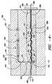
[0043]本開示に従ったダイの一態様の斜視図は、図2及び3に示されている。示されているように、樹脂214は、樹脂の流れ方向244により示されているようにダイ150の中に流れる。樹脂214はダイ150の中に分配され、そしてロービング142と相互作用する。ロービング142はロービング走行方向282でダイ150の中を通って横に移動され、そして樹脂214でコーティングされる。次いでロービング142は樹脂214で含浸されて、これらの含浸ロービング142はダイ150を出る。 [0043] A perspective view of one embodiment of a die according to the present disclosure is shown in FIGS. As shown, the
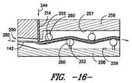
[0044]含浸ダイの中では、ロービングにポリマー樹脂214を含浸するために、含浸ゾーン250の中を通ってロービング142が横に移動するのが通常、好ましい。含浸ゾーン250では、ポリマー樹脂は通常、含浸ゾーン250に作り出された剪断力と圧力とによりロービングの中を通って横方向に推し進められて、これにより含浸の程度を大きく増進させる。これは、高い繊維含有量、たとえば約35%重量分率(weight fraction:Wf)以上、態様によっては約40%Wf以上のリボンから複合体を成形する際に特に有用である。通常、ダイ150は複数の接触面252、たとえば少なくとも2つ、少なくとも3つ、4〜7つ、2〜20、2〜30、2〜40、2〜50、またはより多くの接触面252を含んで、ロービング142上に十分な程度の浸透力及び圧力を作りだす。これらの特有の形状は変動することができるが、接触面252は通常、湾曲した突出部片(curved lobe)、ピンなどの曲線のある表面をもつ。接触面252も通常、金属材料から製造される。 [0044] Within the impregnation die, it is generally preferred that the roving 142 move laterally through the
[0045]図4は、含浸ダイ150の断面図を示す。示されているように、含浸ダイ150は、多岐管アセンブリ220及び含浸区分を含むことができる。含浸区分は、ゲートアセンブリ270及び含浸ゾーン250を包含する。多岐管アセンブリ220は、その中を通ってポリマー樹脂214が流れるように設けられている。たとえば多岐管アセンブリ220は、チャネル222または複数のチャネル222を含むことができる。含浸ダイ150に提供される樹脂214は、チャネル222の中を通って流れることができる。 [0045] FIG. 4 shows a cross-sectional view of the impregnation die 150. As shown in FIG. As shown, the impregnation die 150 can include a
[0046]図5〜11に示されているように、例示的な態様では、チャネル222のそれぞれの一部は曲線をなすことができる。曲線部分によって、多岐管アセンブリ220の中を通って樹脂214を分配するために様々な方向に樹脂214を比較的滑らかに向けなおす(redirection)ことができ、チャネル222の中を通って樹脂214を比較的滑らかに流すことができる。あるいは、チャネル222は線状でありえ、樹脂214を向けなおすのは、チャネル222の直線部分の間の比較的角張った移行領域を経ることができる。チャネル222は任意の好適な形状、サイズ及び/または輪郭を有することができると理解すべきである。 [0046] As illustrated in FIGS. 5-11, in an exemplary embodiment, each portion of
[0047]図5〜11に示されているように、例示的な態様では、複数のチャネル222は複数の分岐ランナー222でありえる。ランナー222は、第一の分岐ランナー群232を含むことができる。前記第一の分岐ランナー群232は、樹脂214を多岐管アセンブリ220に提供する最初の単数または複数種類のチャネル222から分岐している複数のランナー222を含むことができる。第一の分岐ランナー群232は、最初のチャネル222から分岐する2つ、3つ、4つまたはそれ以上のランナー222を含むことができる。 [0047] As illustrated in FIGS. 5-11, in an exemplary embodiment, the plurality of
[0048]所望により、ランナー222は、図5及び7〜11に示されているように、第一の分岐ランナー群232から分岐する第二の分岐ランナー群234を含むことができる。たとえば、第二の分岐ランナー群234からの複数のランナー222は、第一の分岐ランナー群232の一つ以上のランナー222から分岐することができる。第二の分岐ランナー群234は、第一の分岐ランナー群232のランナー222から分岐する2つ、3つ、4つ以上のランナー222を含むことができる。 [0048] Optionally, the
[0049]所望により、ランナー222は、図5及び8〜9に示されているように、ダイ二の分岐ランナー群234から分岐する第三の分岐ランナー群236を含むことができる。たとえば、第三の分岐ランナー群236からの複数のランナー222は、第二の分岐ランナー群234の一つ以上のランナー222から分岐することができる。第三の分岐ランナー群236は、第二の分岐ランナー群234のランナー222から分岐する2つ、3つ、4つ以上のランナー222を含むことができる。 [0049] Optionally, the
[0050]図5〜11に示されているように、例示的な態様によっては、複数の分岐ランナー222は、中心軸224に沿って対称の位置づけになっている。分岐ランナー222及びその対称の位置づけは、多岐管アセンブリ220を出て、ロービング142をコーティングする樹脂214の流れが実質的にロービング142上に均一に分配されるような具合に、樹脂214を均一に分配する。これによって、通常、ロービング142の均一な含浸が可能になる。 [0050] In some exemplary aspects, the plurality of
[0051]さらに、多岐管アセンブリ220は、態様によっては出口領域242を画定する。出口領域242は、樹脂214が多岐管アセンブリ220を出る多岐管アセンブリ220のその部分である。従って、出口領域242は、通常、樹脂214が出るチャネルまたはランナー222の少なくとも下流部分を含む。態様によっては、図5〜10に示されているように、出口領域242に配置されたチャネルまたはランナー222の少なくとも一部は、樹脂214の流れ方向244の面積が次第に増加する。面積が次第に増加すると、樹脂214が多岐管アセンブリ220の中を通って流れるにつれて樹脂214を拡散でき、より分配することができるので、ロービング142上に樹脂214を実質的に均一に分配できる。これに加えて、またはあるいは、出口領域242に配置された様々なチャネルまたはランナー222は、図11に示されているように、樹脂214の流れ方向244に一定の面積を持つことができ、また、樹脂214の流れ方向244の面積が減少することもできる。 [0051] Furthermore, the
[0052]図5に示されているように、態様によっては、出口領域242に配置されたチャネルまたはランナー222のそれぞれは、そこから流れる樹脂214が、出口領域242に配置された他のチャネルまたはランナー222からの樹脂214と混和する(combine)ように配置される。出口領域242に配置された様々なチャネルまたはランナー222から樹脂214が混和することにより、多岐管アセンブリ220から樹脂214の単一且つ均一に分配した流れを生み出して、ロービング142を実質的に均一にコーティングする。あるいは、図10及び11に示されているように、出口領域242に配置された様々なチャネルまたはランナー222は、そこから流れる樹脂214が、出口領域242に配置された他のチャネルまたはランナー222からの樹脂214とは別々になる(discrete)ように配置することができる。これらの態様において、複数の別々の、しかし通常、均一分配された樹脂の流れ214は、ロービング142を実質的に均一にコーティングするための多岐管アセンブリ220により生み出すことができる。 [0052] As shown in FIG. 5, in some embodiments, each of the channels or
[0053]図4に示されているように、出口領域242に配置されたチャネルまたはランナー222の少なくとも一部は、曲線の断面プロフィールをもつ。これらの曲線プロフィールにより、樹脂214は、チャネルまたはランナー222からロービング142の方へ、通常、徐々に下向きに向けることができる。あるいは、これらのチャネルまたはランナー222は、任意の好適な断面プロフィールをもつことができる。 [0053] As shown in FIG. 4, at least a portion of the channel or
[0054]本開示は、多岐管アセンブリ220の上記開示の態様に限定されないと理解すべきである。むしろ、任意の好適な多岐管アセンブリ220は本開示の趣旨及び範囲内に含まれる。特に、コートハンガー、馬蹄、フレックスフリップ(flex-flip)または調節可能なスロット多岐管アセンブリなどの、通常、樹脂214の均一分配を提供しえる多岐管アセンブリ220は、本開示の趣旨及び範囲内である。 [0054] It should be understood that the present disclosure is not limited to the above-disclosed aspects of the
[0055]図4及び5にさらに示されているように、多岐管アセンブリ220の中を通って流れた後、樹脂214はゲート通路270の中を通って流れることができる。ゲート通路270は多岐管アセンブリ220と含浸ゾーン250との間に配置され、樹脂214がロービング142をコーティングするように、多岐管アセンブリ220から樹脂214を流すために設けられる。従って、たとえば出口領域242の中通って多岐管アセンブリ220を出る樹脂214は、ゲート通路270に入り、その中を通って流れることができる。 [0055] As further shown in FIGS. 4 and 5, after flowing through the
[0056]図4に示されているように、態様によっては、ゲート通路270は、多岐管アセンブリ220と含浸ゾーン250との間を垂直に伸長する。あるいは、ゲート通路270は、樹脂214がその中を通って流れるように、垂直と水平との間の任意の好適な角度で伸長することができる。 [0056] As shown in FIG. 4, in some embodiments, the
[0057]さらに図4に示されているように、態様によっては、ゲート通路270の少なくとも一部は、樹脂214の流れ方向244で断面プロフィールが縮小する。ゲート通路270の少なくとも一部がテーパー状になっていると、その中を通って流れる樹脂214の流速が増加してからロービング142と接触できるので、ロービング142上で樹脂214を衝突(impinge)させることができる。樹脂214によるロービング142の初期衝突により、以下に記載するように、ロービングのさらなる衝突を提供する。さらに、ゲート通路270の少なくとも一部がテーパー状になっていると、ゲート通路270と多岐管アセンブリ220の背圧を増加することができ、これにより樹脂214がより均一に分配して、ロービング142をコーティングすることができる。あるいは、ゲート通路270は、所望によりまたは必要により、増加する断面プロフィールまたは、通常一定の断面プロフィールをもつことができる。 [0057] As further illustrated in FIG. 4, in some embodiments, at least a portion of the
[0058]図6に示されているように、ダイ150の多岐管アセンブリ220及びゲート通路270を出ると、樹脂214は、ダイ150の中を通って横に移動するロービング142と接触する。上記のように、多岐管アセンブリ220及びゲート通路270に樹脂214が分配されるため、樹脂214はロービング142を実質的に均一にコーティングすることができる。図13〜17に示されているように、さらに態様によっては、樹脂214はロービング142のそれぞれのゲート通路270に面している上部表面216、若しくは表面216、またはロービング142それぞれの下部表面、またはロービング142それぞれの上部及び下部表面の両方に衝突することができる。ロービング142上で最初に衝突することによって、さらにロービング142に樹脂214を含浸する。ロービング142上での衝突は、樹脂がロービング142に衝突するときは樹脂214の速度、樹脂が多岐管アセンブリ220若しくはゲート通路270を出るときはロービング142の樹脂214への近接性、または他の様々な変数により促進することができる。 [0058] Upon exiting the
[0059]図4に示されているように、コーティング済ロービング142は、含浸ゾーン250の中を通って走行方向282に横に移動する。含浸ゾーン250は、たとえばその間に配置されたゲート通路270の中を通って多岐管アセンブリ220と流体連通している。含浸ゾーン250は、ロービング142に樹脂214を含浸するように構成されている。 [0059] As shown in FIG. 4, the coated roving 142 moves laterally through the
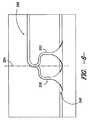
[0060]たとえば上述のように、図4及び12〜17に示されているように態様によっては、含浸ゾーン250は複数の接触面252を包含する。ロービング142は、含浸ゾーンの接触面252上を横に移動する。接触面252上にロービング142が衝突すると、ロービング142をコーティングする樹脂214をロービング142に浸み込ませるのに十分な剪断力と圧力を生み出す。 [0060] For example, as described above, in some embodiments, as shown in FIGS. 4 and 12-17, the
[0061]図4及び図13〜17に示されているように、態様によっては、含浸ゾーン250は、二つの相隔たって対立するプレート256と258の間に画定される。第一のプレート256は第一の内部表面257を画定し、第二のプレート258は第二の内部表面259を画定する。含浸ゾーン250は第一のプレート256と第二のプレート258との間に画定される。接触面252は、第一及び第二の内部表面257と259の両方の上で画定されるか、若しくはその両方から伸長するか、または第一及び第二の内部表面257と259の一方のみの上で画定されるか、若しくはそこから伸長することができる。 [0061] As shown in FIGS. 4 and 13-17, in some embodiments, the
[0062]図4、13及び15〜17に示されているように、例示的な態様では、接触面252は、ロービングが第一及び第二の表面257と259の上の接触面252上で交互に衝突するように、第一及び第二の表面257と259上で交互に画定することができる。かくして、ロービング142は、波形、蛇行または正弦曲線型の通路で接触面252を通過して、これにより剪断力が増強する。 [0062] As shown in FIGS. 4, 13, and 15-17, in an exemplary embodiment, the
[0063]ロービング142が接触面252を横断する角度254は、通常、剪断力及び圧力を増強するのに十分に大きくてもよいが、繊維を破壊する過剰な力をもたらすほど大きくてはいけない。かくして、たとえば角度254は約1°〜約30°の範囲、態様によっては約5°〜約25°の範囲でありえる。 [0063] The
[0064]上記のように、接触面252は通常、湾曲した突出部片、ピンなどの曲線のある表面をもつ。さらに多くの例示的な態様では、含浸ゾーン250は波形の断面プロフィールをもつ。図4、12及び13に示されているように例示的な態様では、接触面252は第一及び第二のプレート256及び258の両方の波形表面の一部を形成し、波形の断面プロフィールを画定する突出部(lobe)である。図12は、これらの態様に従った含浸ゾーン250の少なくとも一部を形成する、その上の第二のプレート258及び様々な接触面を示す。 [0064] As described above, the
[0065]図14に示されているように他の態様では、接触面252は、第一または第二のプレート256または258のたった一方が波形表面の一部を形成する突出部である。これらの態様において、衝突は、一つのプレートの表面上の接触面252の上でのみ起きる。もう一つのプレートは、通常、平坦であるか、またはコーティング済ロービングと相互作用が全くおきないように形作ることができる。 [0065] In another aspect, as shown in FIG. 14, the
[0066]図15〜17に示されているように他の態様では、含浸ゾーン250は、複数のピン(またはロッド)260を含むことができ、それぞれのピンは接触面252を有する。ピン260は、図15及び16に示されているように固定(static)されているか、自由回転であるか(示されていない)、または図17に示されているように回転駆動でありえる。ピン260は、図15に示されているように、含浸ゾーンを画定しているプレート表面に直接据え付けることができるか、または図16及び17に示されているように表面から隔てることができる。ピン260はヒーター133により加熱することができるか、または個別に若しくは所望により若しくは必要により加熱することができることに留意すべきである。さらにピン260はダイ150内に含まれるか、またはダイ150から外側に伸長することができ、その中に完全に包み込まれなくてもよい。 [0066] In other embodiments, as shown in FIGS. 15-17, the
[0067]さらなる態様では、接触面252及び含浸ゾーン250は、所望により若しくは必要により、ロービング142に樹脂214を含浸するための任意の好適な形状及び/または構造体を含むことができる。 [0067] In further embodiments, the
[0068]ロービング142をさらに含浸し易くするために、これらはダイ150の中、特に含浸ゾーン250の中にある間は、張力下に保持することもできる。たとえば張力は、ロービング142当たり、または繊維のトウ当たり、約5〜約300ニュートンを変動し、態様によっては約50〜約250ニュートン、態様によっては約100〜約200ニュートンを変動しえる。 [0068] To facilitate further impregnation of the
[0069]図4並びに図18及び19に示されているように、態様によってはランドゾーン(land zone)280は、ロービング142の走行方向282の含浸ゾーン250下流に配置することができる。ロービング142はランドゾーン280の中を通って横に移動してから、ダイ150を出ることができる。図18に示されているように、態様によっては、ランドゾーン280の面積が増加するように、ランドゾーン280の少なくとも一部は走行方向282に増加する断面プロフィールをもつことができる。増加する部分は、ロービング142がダイ150を出やすくするために、ランドゾーン280の下流部分でありえる。あるいは、断面プロフィールまたはその任意の部分は縮小することができるか、図19に示されているように一定であることができる。 [0069] As shown in FIG. 4 and FIGS. 18 and 19, in some embodiments, a
[0070]図4にさらに示されているように、態様によっては、面板290は含浸ゾーン250に隣接することができる。面板290は通常、含浸ゾーン250、含まれる場合には走行方向282のランドゾーン280の下流に配置することができる。面板290は通常、ロービング142から余分の樹脂214を計量(meter)するように構成される。かくしてロービング142がその中を通って横に移動する面板290の開口部は、ロービング142がその中を通って横断するときに、開口部のサイズが、ロービング142から余分の樹脂214を除去するような大きさにすることができる。 [0070] As further shown in FIG. 4, in some embodiments, the
[0071]さらに他の構成成分を場合により使用して、繊維の含浸を助けることができる。たとえば、「ガスジェット」アセンブリを特定の態様で使用して、個別の繊維のロービングを均等に分散しやすくすることができ、これは合体させたトウの幅全体にわたって、24,000本もの繊維まで含むことができる。これにより強度特性を均等に分散させるのに役立つ。そのようなアセンブリとしては、出口ポートを通過する移動ロービング上に通常、垂直様式で衝突する圧縮空気または他の気体の供給を含むことができる。次いで分散したロービングを、上記のように含浸させるためにダイに導入することができる。 [0071] Still other components may optionally be used to aid in fiber impregnation. For example, the “gas jet” assembly can be used in a specific manner to facilitate even distribution of individual fiber rovings, including up to 24,000 fibers across the combined tow width. Can do. This helps to distribute the strength characteristics evenly. Such assemblies can include a supply of compressed air or other gas that typically impinges in a vertical manner on moving rovings that pass through the exit port. The dispersed roving can then be introduced into a die for impregnation as described above.
[0072]本開示に従ったダイ及び方法を使用して得られた含浸ロービングは、非常に低い空隙比(void fraction)をもつことができ、これによりその強度を高めやすくなる。たとえば、空隙比は約3%以下、態様によっては約2%以下、態様によっては約1%以下、態様によっては約0.5%以下である。空隙比は、当業者に公知の方法を使用して測定することができる。たとえば空隙比は、サンプルをオーブン(たとえば約600℃で3時間)に設置して樹脂を燃やし尽くす、「樹脂燃焼(resin burn off)」試験を使用して測定することができる。次いで、残った繊維の質量を測定して、重量と容積比(volume fraction)を計算することができる。そのような「燃焼」試験は、ASTM D 2584-08に従って実施して、繊維とポリマーマトリックスの重量を測定することができ、次いでこれを使用して、以下の等式: [0072] Impregnated roving obtained using a die and method according to the present disclosure can have a very low void fraction, which tends to increase its strength. For example, the void ratio is about 3% or less, in some embodiments about 2% or less, in some embodiments about 1% or less, and in some embodiments about 0.5% or less. The void ratio can be measured using methods known to those skilled in the art. For example, the void ratio can be measured using a “resin burn off” test where the sample is placed in an oven (eg, about 600 ° C. for 3 hours) to burn out the resin. The mass of the remaining fiber can then be measured and the weight and volume fraction can be calculated. Such a “burning” test can be performed according to ASTM D 2584-08 to measure the weight of the fiber and polymer matrix, which can then be used to formulate the following equation:
{式中、Vfは百分率としての空隙比である;
ρcは、公知方法、たとえば液体または気体比重瓶法(pycnometer)(たとえばヘリウム比重瓶法)を使用して測定した複合体の密度である;
ρtは、複合体の理論密度であり、以下の等式より決定される:{Where Vf is the void ratio as a percentage;
ρc is the density of the complex measured using known methods such as liquid or gas pycnometer (eg helium pycnometer);
ρt is the theoretical density of the complex and is determined from the following equation:
(ρmはポリマーマトリックスの密度である(たとえば好適な結晶度における);
ρfは繊維の密度である;
Wfは繊維の重量分率である;及び
Wmはポリマーマトリックスの重量分率である)}をベースとした「空隙比」を計算することができる。(ρm is the density of the polymer matrix (eg at a suitable crystallinity);
ρf is the density of the fiber;
Wf is the weight fraction of the fiber; and
Wm is the weight fraction of the polymer matrix)} and the “void ratio” can be calculated.
[0073]あるいは、空隙比は、ASTM D 3171-09に従って樹脂を化学的に溶解させることによって測定することができる。「燃焼」及び「溶解」法は、通常、融解及び化学溶解に耐性であるガラス繊維に特に適している。しかしながら他の場合には、空隙比は、ASTM D 2734-09(方法A)に従ってポリマー、繊維、及びリボンの密度をベースとして間接的に計算することができ、ここで密度はASTM D792-08方法Aにより測定することができる。もちろん、空隙比は慣用の顕微鏡装置を使用して見積もることができる。 [0073] Alternatively, the void ratio can be measured by chemically dissolving the resin according to ASTM D 3171-09. The “burning” and “melting” methods are usually particularly suitable for glass fibers that are resistant to melting and chemical melting. In other cases, however, the void ratio can be calculated indirectly based on the density of polymers, fibers, and ribbons according to ASTM D 2734-09 (Method A), where the density is determined by the ASTM D792-08 method. A can be measured. Of course, the void ratio can be estimated using a conventional microscope apparatus.
[0074]本開示は、少なくとも一つの繊維ロービング142または複数の繊維ロービング142にポリマー樹脂214を含浸するための方法に関する。本方法は、上記のように、複数の繊維ロービング142の表面216に樹脂214を衝突させること、及び複数のロービング142を樹脂214で実質的に均一にコーティングすることを包含する。さらに本方法は、上記のように複数のコーティング済ロービング142に樹脂214を含浸するために、含浸ゾーン250の中を通して複数のコーティング済ロービング142を横に移動させることを包含する。 [0074] The present disclosure relates to a method for impregnating at least one fiber roving 142 or a plurality of
[0075]上記のように、態様によっては、本方法はさらに、ゲート通路270の中を通して樹脂214を流すことを含みえる。さらに本方法は、上記のように、含浸ゾーン250からランドゾーン280の中を通してロービング142を横に移動させること及び/または面板290の中を通してロービング142を横に移動させることを包含する。 [0075] As noted above, in some embodiments, the method may further comprise flowing
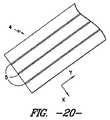
[0076]上記のように、含浸ダイ150を出た後、含浸済ロービング142、または押出物152は、リボンの形状に強化することができる。それぞれのリボンで使用されるロービング数は変動しえる。しかしながら、通常、リボンは2〜20個のロービングを含み、態様によっては2〜10個のロービング、態様によっては3〜5個のロービングを含むことができる。態様によっては、ロービングは、リボンの中で互いにほぼ同一距離で離れているのが望ましい。たとえば図20及び21を参照すると、−x方向に互いに等距離に離れた三つ(3)のロービング5を含む、強化リボン4の一態様が示されている。 [0076] As described above, after exiting the impregnation die 150, the impregnated roving 142, or
[0077]特定の用途に関しては、本開示に従って押出プロセスをさらに利用することができる。たとえば態様によっては、そのようなプロセスを使用してロッドを成形することができる。このような態様では、ロービング142の連続繊維は縦方向に配向されて(図1のシステムの機械方向A)、引張り強さを強める。繊維の配向に加えて、押出プロセスの他の側面も制御して所望の強度を達成する。たとえば比較的高い割合の連続繊維を強化リボンで使用して、強化された強度特性を提供する。たとえば、連続繊維は通常、リボンの約25重量%〜約80重量%、態様によっては約30重量%〜約75重量%、態様によっては約35重量%〜約60重量%を構成する。同様に、(単数または複数種類の)ポリマーは、リボンの約20重量%〜約75重量%、態様によっては約25重量%〜約70重量%、態様によっては約40重量%〜約65重量%を構成する。 [0077] For certain applications, an extrusion process can be further utilized in accordance with the present disclosure. For example, in some embodiments, such a process can be used to form a rod. In such an embodiment, the continuous fibers of roving 142 are oriented in the machine direction (machine direction A of the system of FIG. 1) to increase the tensile strength. In addition to fiber orientation, other aspects of the extrusion process are also controlled to achieve the desired strength. For example, a relatively high percentage of continuous fibers are used in the reinforcing ribbon to provide enhanced strength properties. For example, continuous fibers typically comprise from about 25% to about 80%, in some embodiments from about 30% to about 75%, and in some embodiments from about 35% to about 60% by weight of the ribbon. Similarly, the polymer (s) may comprise from about 20% to about 75%, in some embodiments from about 25% to about 70%, in some embodiments from about 40% to about 65% by weight of the ribbon. Configure.
[0078]通常、リボンは含浸ダイ150から直接押出システムに供給することができるか、またはスピンドル若しくは他の好適な貯蔵装置から供給することができる。張力を制御する装置を使用して、リボンが押出システムの中を通して引っ張られるのにつれて、リボン内での張力の程度を制御し易くするのに使用することができる。リボンを加熱するデバイスには、オーブンを供給することができる。次いでリボンを強化ダイに供給することができ、この強化ダイは、リボンを一緒にプレフォーム(preform)に圧縮し、並びに整列し、ロッドなどの所望の製品の初期形状を成形するように操作することができる。所望により、プレフォームを最終形状に圧縮する、第二のダイ(たとえばキャリブレーションダイ)も使用することができる。ダイの間及び/またはいずれかのダイの後に冷却システムをさらに組み入れることができる。下流の引き取り装置は、システムの中を通して、製品を引っ張るために配置することができる。 [0078] Typically, the ribbon can be fed directly from the impregnation die 150 to the extrusion system or from a spindle or other suitable storage device. A tension control device can be used to help control the degree of tension in the ribbon as it is pulled through the extrusion system. An oven can be supplied to the device that heats the ribbon. The ribbon can then be fed into a reinforced die that operates to compress the ribbon together into a preform as well as align and shape the initial shape of the desired product, such as a rod. be able to. If desired, a second die (eg, a calibration die) that compresses the preform to a final shape can also be used. A cooling system may further be incorporated between the dies and / or after any dies. A downstream take-off device can be arranged to pull the product through the system.
[0079]本発明のこれら及び他の変形及び変更は、本発明の趣旨及び範囲を逸脱することなく、当業者により実施しえる。さらに様々な態様の側面は、全体においてまたは一部分において交換可能であることは理解すべきである。さらに、当業者は、上記記載は単なる例示であって、付記請求の範囲に記載された発明を限定するものではないことを理解するだろう。 [0079] These and other variations and modifications of the invention may be made by those skilled in the art without departing from the spirit and scope of the invention. Further, it should be understood that aspects of the various embodiments may be interchanged in whole or in part. Furthermore, those skilled in the art will appreciate that the above description is illustrative only and is not intended to limit the invention described in the appended claims.
Claims (7)
Translated fromJapanese複数のロービング(142)に樹脂(214)を含浸するように構成されている含浸ゾーン(250)、ここで、含浸ゾーン(250)が複数の曲線の接触面(252)を含み、複数の接触面(252)のそれぞれは、複数のロービング(142)が1度〜30度の範囲のある角度(254)で接触面(252)を横に移動するように構成され、含浸ゾーン(250)は波形の断面プロフィールをもつ;及び
樹脂(214)がゲート通路(270)に面する複数のロービング(142)それぞれの表面(216)に衝突し、複数のロービング(142)を実質的に均一コーティングするように、その中を通して樹脂(214)を流すための含浸ゾーン(250)と流体連通しているゲート通路(270)、ここで、前記ゲート通路(270)は、含浸ゾーン(250)に対して垂直に伸長し、複数のロービング(142)の走行方向(282)において、含浸ゾーン(250)の全ての接触面(252)の上流に配置されており、ゲート通路(270)の少なくとも一部は、樹脂(214)の流れ方向(244)の断面プロフィールが徐々に縮小する;
を含む、前記含浸区分。An impregnation section of a die (150) for impregnating a plurality of fiber rovings (142) with a polymer resin (214),
Impregnation zone configured to impregnate the resin (214) into a plurality of rovings (142) (250), wherein the impregnation zone (250) isviewed contains the contact surfacesof a plurality ofcurves(252), a plurality of Each of the contact surfaces (252) is configured such that a plurality of rovings (142) move laterally across the contact surface (252) at an angle (254) ranging from 1 degree to 30 degrees, and the impregnation zone (250) Has a corrugated cross-sectional profile ; and the resin (214) impinges on the surface (216) of each of the plurality of rovings (142) facing the gate passageway (270) to substantially coat the plurality of rovings (142) A gate passage (270) in fluid communication with an impregnation zone (250) for flowing resin (214) therethrough, wherein said gate passage (270) is relative to the impregnation zone (250) In the traveling direction (282) of the plurality of rovings (142), and arranged upstream of all the contact surfaces (252) of the impregnation zone (250).Cage, at least a portion of the gate passage (270) cross-sectional profile of the resin flow direction (214) (244) is gradually reduced;
Said impregnation section.
Applications Claiming Priority (1)
| Application Number | Priority Date | Filing Date | Title |
|---|---|---|---|
| PCT/US2011/032080WO2012141689A1 (en) | 2011-04-12 | 2011-04-12 | Impregnation section of die and method for impregnating fiber rovings |
Related Child Applications (1)
| Application Number | Title | Priority Date | Filing Date |
|---|---|---|---|
| JP2016171395ADivisionJP6246288B2 (en) | 2016-09-02 | 2016-09-02 | Die impregnation section and method for impregnating fiber roving |
Publications (2)
| Publication Number | Publication Date |
|---|---|
| JP2014518531A JP2014518531A (en) | 2014-07-31 |
| JP6045566B2true JP6045566B2 (en) | 2016-12-14 |
Family
ID=44625971
Family Applications (1)
| Application Number | Title | Priority Date | Filing Date |
|---|---|---|---|
| JP2014505111AActiveJP6045566B2 (en) | 2011-04-12 | 2011-04-12 | Die impregnation section and method for impregnating fiber roving |
Country Status (5)
| Country | Link |
|---|---|
| US (2) | US20140037842A1 (en) |
| EP (2) | EP2697041B1 (en) |
| JP (1) | JP6045566B2 (en) |
| CN (1) | CN103547440B (en) |
| WO (1) | WO2012141689A1 (en) |
Cited By (1)
| Publication number | Priority date | Publication date | Assignee | Title |
|---|---|---|---|---|
| JP2017039322A (en)* | 2016-09-02 | 2017-02-23 | ティコナ・エルエルシー | Die impregnation section and method for impregnating fiber roving |
Families Citing this family (17)
| Publication number | Priority date | Publication date | Assignee | Title |
|---|---|---|---|---|
| CN108407338B (en) | 2011-04-12 | 2021-05-11 | 提克纳有限责任公司 | Die and method for impregnating fiber rovings |
| PL2701886T3 (en) | 2011-04-29 | 2017-06-30 | Ticona Llc | Die with flow diffusing gate passage and method for impregnating fiber rovings |
| EP2917025A1 (en)* | 2012-11-09 | 2015-09-16 | Evonik Röhm GmbH | Use and production of coated filaments for extrusion-based 3d printing processes |
| CN103510313A (en)* | 2013-10-21 | 2014-01-15 | 江苏海大印染机械有限公司 | Wound-rotor type integrated mould for dying and twisting colored spun yarns |
| CN103526484B (en)* | 2013-10-21 | 2015-09-16 | 江苏海大印染机械有限公司 | Colour-spun yarns half packed dyeing die head |
| CN103753831A (en)* | 2014-02-12 | 2014-04-30 | 台州市家得宝科技有限公司 | Dipping mold and dipping method for continuous fiber reinforced thermoplastic composite materials |
| KR101551067B1 (en) | 2014-03-04 | 2015-09-07 | 현대자동차주식회사 | Novel System for impregnating Thermo-hardening Resin |
| CN103847042B (en)* | 2014-03-10 | 2016-06-29 | 浙江省遂昌金矿有限公司 | Particular manufacturing craft and dipping method for continuous fiber and resins synthesis |
| KR101552334B1 (en) | 2014-03-25 | 2015-09-10 | 도레이첨단소재 주식회사 | Slot-die type impregnation pin and manufacturing apparatus for continuous fiber composite |
| DE102014016289A1 (en)* | 2014-11-04 | 2016-05-04 | Protec Polymer Processing Gmbh | Method for producing unidirectionally fiber-reinforced plastic material and device for impregnating fiber material with extruded plastic |
| KR101740657B1 (en) | 2016-07-01 | 2017-05-26 | 롯데케미칼 주식회사 | Method for manufacturing long fiber reinforced thermoplastic |
| KR101740658B1 (en) | 2016-07-04 | 2017-05-26 | 롯데케미칼 주식회사 | Apparatus for manufacturing long fiber reinforced thermoplastic |
| US10723088B2 (en) | 2016-09-29 | 2020-07-28 | Toray Industries, Inc. | Fiber-reinforced thermoplastic-resin base and molded article obtained therefrom |
| CN109514889B (en)* | 2018-12-28 | 2021-04-09 | 中广核俊尔新材料有限公司 | Cordwood fiber dipping die capable of being assembled |
| GB202017398D0 (en)* | 2020-11-03 | 2020-12-16 | Blade Dynamics Ltd | Hybrid pultrusion plates for a spar cap of a wind turbine blade |
| CN115230157A (en)* | 2022-07-01 | 2022-10-25 | 武汉理工大学 | Controllable 3D of adjustable line footpath of pressure prints and uses compound silk preparation facilities |
| CN115055329B (en)* | 2022-07-04 | 2024-04-26 | 界首市欧思润体育用品有限公司 | An automatic varnishing equipment for carbon fiber fishing rod surface |
Family Cites Families (146)
| Publication number | Priority date | Publication date | Assignee | Title |
|---|---|---|---|---|
| US1078448A (en) | 1912-05-22 | 1913-11-11 | Universal Winding Co | Tension device. |
| US1111500A (en) | 1914-06-29 | 1914-09-22 | George J Schautz | Thread-tension device. |
| GB326778A (en) | 1928-09-13 | 1930-03-13 | British Celanese | Improvements in or relating to the production of artificial filaments, yarns, or threads |
| US3647526A (en) | 1966-05-13 | 1972-03-07 | Donald A Barnes | Method for treating textile materials |
| US3803965A (en) | 1972-05-24 | 1974-04-16 | Steelastic Co | Apparatus for producing reinforced fabric |
| US4017240A (en) | 1975-11-19 | 1977-04-12 | Rubbermaid Incorporated | Die for extruding sheet material |
| USRE32772E (en) | 1979-09-13 | 1988-10-25 | Polymer Composites, Inc. | Method of manufacturing a composite reinforcing structure |
| JPS58138616A (en) | 1982-02-13 | 1983-08-17 | Kato Hatsujo Kaisha Ltd | Glass fiber reinforced molding material and manufacturing device thereof |
| US4565153A (en) | 1984-01-16 | 1986-01-21 | Shell Oil Company | Apparatus for impregnation of reinforcing fibers |
| US4588538A (en) | 1984-03-15 | 1986-05-13 | Celanese Corporation | Process for preparing tapes from thermoplastic polymers and carbon fibers |
| US4720366A (en) | 1984-06-07 | 1988-01-19 | E. I. Du Pont De Nemours And Company | Method for producing fiber reinforced thermoplastic material |
| US4531959A (en) | 1984-10-04 | 1985-07-30 | Corning Glass Works | Method and apparatus for coating optical fibers |
| US4643126A (en)* | 1984-11-21 | 1987-02-17 | The Budd Company | Method and apparatus for impregnating fiber strands |
| US4728387A (en) | 1986-12-15 | 1988-03-01 | General Electric Company | Resin impregnation of fiber structures |
| US4775434A (en) | 1987-01-30 | 1988-10-04 | Rolston J Albert | Resin-stripping die |
| FR2613661B1 (en)* | 1987-04-09 | 1989-10-06 | Atochem | PROCESS FOR PRODUCING CONTINUOUS FIBER REINFORCED THERMOPLASTIC RESIN PROFILES, APPARATUS FOR OBTAINING SAME |
| EP0300321B1 (en) | 1987-07-11 | 1994-03-09 | KABUSHIKI KAISHA KOBE SEIKO SHO also known as Kobe Steel Ltd. | Method of manufacturing continuous fiber-reinforced thermoplastic prepregs and an apparatus for carrying out the same |
| DE3734574A1 (en) | 1987-10-13 | 1989-04-27 | Basf Ag | FILLED SHAPE |
| US4923134A (en) | 1987-11-02 | 1990-05-08 | Underground Technologies, Inc. | Self-propelled subsoil penetrating tool system |
| US4864964A (en) | 1987-12-15 | 1989-09-12 | General Electric Company | Apparatus and method for impregnating continuous lengths of multifilament and multi-fiber structures |
| DE3835575A1 (en) | 1988-10-19 | 1990-04-26 | Bayer Ag | COMPOSITES |
| DE3835574A1 (en)* | 1988-10-19 | 1990-04-26 | Bayer Ag | EXTRUSIONSIMPRAEGNIERWERKZEUG |
| US5277566A (en) | 1988-10-19 | 1994-01-11 | Hoechst Aktiengesellschaft | Extrusion impregnating device |
| CA1336483C (en) | 1989-01-30 | 1995-08-01 | Hatsuo Ishida | Process for preparing composites |
| US5068142A (en) | 1989-01-31 | 1991-11-26 | Teijin Limited | Fiber-reinforced polymeric resin composite material and process for producing same |
| US4992229A (en) | 1989-02-14 | 1991-02-12 | Phillips Petroleum Company | Thermoplastic re-pultrusion |
| FI91373C (en)* | 1989-07-14 | 1994-06-27 | Neste Oy | Method and apparatus for impregnating a continuous fiber bundle |
| US4959534A (en) | 1989-08-28 | 1990-09-25 | At&T Bell Laboratories | Differential optical logic arrangement |
| JPH03119188A (en) | 1989-10-03 | 1991-05-21 | Mitsubishi Kasei Corp | Fiber-reinforced plastic composite material |
| JPH03137161A (en) | 1989-10-21 | 1991-06-11 | Mitsubishi Petrochem Co Ltd | Thermoplastic resin composition |
| GB2240997B (en) | 1990-02-19 | 1993-09-15 | Bridon Plc | Strand or rope product of composite rods |
| US5207850A (en) | 1990-07-17 | 1993-05-04 | General Electric Company | Process for making thermoplastic composites with cyclics oligomers and composites made thereby |
| US5116450A (en) | 1990-07-23 | 1992-05-26 | Phillips Petroleum Company | Molding apparatus |
| US5114516A (en) | 1990-10-05 | 1992-05-19 | Aluminum Company Of America | Method for pultruding fiber-reinforced, thermoplastic stock |
| US5114633A (en) | 1991-05-16 | 1992-05-19 | Shell Oil Company | Method for the resin-impregnation of fibers |
| US5268050A (en) | 1991-06-05 | 1993-12-07 | Ferro Corporation | Process for using an extruder die assembly for the production of fiber reinforced thermoplastic pellets, tapes and similar products |
| DE4121200A1 (en)* | 1991-06-27 | 1993-01-07 | Basf Ag | DEVICE FOR IMPREGNATING FIBER MATERIAL WITH LIQUID PLASTIC |
| JPH0533278A (en) | 1991-07-19 | 1993-02-09 | Toray Ind Inc | Rope comprising carbon fiber-reinforced composite material and production thereof |
| JPH0550432A (en) | 1991-08-23 | 1993-03-02 | Kobe Steel Ltd | Pultrusion apparatus and pultrusion method |
| JPH05148780A (en) | 1991-11-28 | 1993-06-15 | Toray Ind Inc | Production of rope composed of fiber-reinforced composite material |
| DE4223241A1 (en) | 1992-07-15 | 1994-01-20 | Hoechst Ag | Fiber-reinforced semi-finished products made from medium to high-viscosity thermoplastics and processes for their production |
| JPH0671724A (en) | 1992-08-27 | 1994-03-15 | Toray Ind Inc | Resin coating apparatus for fibrous article |
| JP3358850B2 (en)* | 1993-08-17 | 2002-12-24 | 住友化学工業株式会社 | Apparatus for producing long fiber reinforced thermoplastic resin composition, method for producing the same, and coating die for producing the same |
| MY112441A (en) | 1994-03-17 | 2001-06-30 | Shell Int Research | A process of melt impregnation |
| JPH07279940A (en) | 1994-03-31 | 1995-10-27 | Nippon Cable Syst Inc | High bending withstanding rope |
| JP3670321B2 (en) | 1994-10-18 | 2005-07-13 | 住友化学株式会社 | Crosshead die and method for producing long fiber reinforced resin structure |
| AT403448B (en)* | 1994-11-15 | 1998-02-25 | Danubia Petrochem Polymere | EXTRUSION IMPREGNATION DEVICE |
| JPH09103732A (en) | 1995-09-06 | 1997-04-22 | Internatl Business Mach Corp <Ibm> | Fluid feeder |
| CN1066676C (en) | 1995-11-30 | 2001-06-06 | 智索股份有限公司 | Method of mfg. long-fiber-reinforced resin structure, and method and apparatus for mfg. columnar-shaped bodies |
| DE19602638A1 (en) | 1996-01-25 | 1997-08-07 | Inventa Ag | Process for the production of thermally deformable composite materials with polylactam matrix |
| US6045876A (en) | 1996-04-10 | 2000-04-04 | Fellers; John F. | System and method for impregnating a continuous fiber strand with a polymer melt |
| GB9615995D0 (en) | 1996-07-30 | 1996-09-11 | Kobe Steel Europ Ltd | Fibre reinforced compositions and methods for their production |
| US6258453B1 (en) | 1996-09-19 | 2001-07-10 | Lawrence V. Montsinger | Thermoplastic composite materials made by rotational shear |
| JP3774959B2 (en) | 1996-11-06 | 2006-05-17 | 東レ株式会社 | Molding material and manufacturing method thereof |
| US6090319A (en) | 1997-01-14 | 2000-07-18 | Ticona Celstran, Inc. | Coated, long fiber reinforcing composite structure and process of preparation thereof |
| US5911932A (en) | 1997-07-09 | 1999-06-15 | R. Charles Balmer | Method of prepregging with resin |
| KR100221361B1 (en) | 1997-07-14 | 1999-09-15 | 이정국 | The process and apparatus for continuous fiber coating |
| DE69822287T2 (en) | 1997-12-03 | 2005-02-17 | Toray Industries, Inc. | PHENOLIC RESIN COMPOSITIONS FOR FIBER-REINFORCED COMPOSITE MATERIALS, PREPREGES AND METHOD FOR MANUFACTURING FIBER-REINFORCED COMPOSITE MATERIALS |
| US6048598A (en) | 1997-12-17 | 2000-04-11 | Balaba Concrete Supply, Inc. | Composite reinforcing member |
| NO981701D0 (en) | 1998-04-16 | 1998-04-16 | Kvaerner Oilfield Prod As | Compound hybrid rises year |
| US6260343B1 (en) | 1998-05-01 | 2001-07-17 | Wire Rope Corporation Of America, Incorporated | High-strength, fatigue resistant strands and wire ropes |
| US6117591A (en) | 1998-05-27 | 2000-09-12 | Wilson Greatbatch Ltd. | Hydrogen fluoride additive for nonaqueous electrolyte in alkali metal electrochemical cells |
| JP3732953B2 (en) | 1998-06-11 | 2006-01-11 | 村田機械株式会社 | Pull-out molding method and pull-out molding machine for resin reinforced fiber |
| DE19827524A1 (en) | 1998-06-22 | 1999-12-23 | Imab Stiftung Balzers | Compound woven fabric of fibers and polymers |
| JP2000052438A (en)* | 1998-08-11 | 2000-02-22 | Sulzer Innotec Ag | Manufacture of body of continuous shape composed of fiber and plastic compound material, and plant for carrying out the manufacture |
| EP1033435A1 (en) | 1999-03-04 | 2000-09-06 | N.V. Bekaert S.A. | Steel cord with polymer core |
| US6346325B1 (en) | 1999-07-01 | 2002-02-12 | The Dow Chemical Company | Fiber-reinforced composite encased in a thermoplastic and method of making same |
| DE19930920A1 (en) | 1999-07-06 | 2001-01-11 | Fact Future Advanced Composite | Long fiber reinforced thermoplastic material and method of making the same |
| US6244014B1 (en) | 1999-07-22 | 2001-06-12 | Andrew Barmakian | Steel rod-reinforced plastic piling |
| AU2931201A (en) | 2000-01-13 | 2001-07-24 | Fulcrum Composites, Inc. | Process for in-line forming of pultruded composites |
| US6248262B1 (en) | 2000-02-03 | 2001-06-19 | General Electric Company | Carbon-reinforced thermoplastic resin composition and articles made from same |
| ATE411607T1 (en) | 2000-02-08 | 2008-10-15 | Brandt Goldsworthy & Associate | ELECTRICAL REINFORCED TRANSMISSION COMPOUND CONDUCTOR |
| JP4461565B2 (en) | 2000-04-25 | 2010-05-12 | 日東紡績株式会社 | Manufacturing apparatus and manufacturing method of long glass fiber pellet |
| FR2807967B1 (en) | 2000-04-25 | 2003-01-17 | Lapeyre | JOINING ELEMENT FORMED FROM EXTRUDABLE ORGANIC MATERIAL REINFORCED BY REINFORCING FIBERS, METHOD AND DEVICE FOR MANUFACTURING |
| NO321272B1 (en) | 2000-05-31 | 2006-04-10 | Aker Kvaerner Subsea As | The tension member |
| US6329056B1 (en) | 2000-07-14 | 2001-12-11 | 3M Innovative Properties Company | Metal matrix composite wires, cables, and method |
| US6344270B1 (en) | 2000-07-14 | 2002-02-05 | 3M Innovative Properties Company | Metal matrix composite wires, cables, and method |
| US6669993B2 (en)* | 2000-09-19 | 2003-12-30 | Honeywell International Inc. | High speed yarn finish application |
| US6783716B2 (en) | 2000-09-29 | 2004-08-31 | Cool Options, Inc. | Nozzle insert for long fiber compounding |
| IT1319599B1 (en) | 2000-12-20 | 2003-10-20 | Rosaldo Fare | MELT-BLOWN HEAD AND CONTROLLED FEEDING PROCEDURE FOR THE PRODUCTION OF POLYMERIC MATERIAL FIBRILLES |
| JP2004528488A (en) | 2001-02-15 | 2004-09-16 | ナムローゼ・フェンノートシャップ・ベーカート・ソシエテ・アノニム | Structure composed of metal ropes and metal ropes |
| US6763869B2 (en)* | 2001-03-07 | 2004-07-20 | Chisso Corporation | Device for producing thermoplastic resin continuous length sections reinforced with long fibers |
| US6658836B2 (en) | 2001-03-14 | 2003-12-09 | The Goodyear Tire & Rubber Company | Hybrid cord |
| WO2002095101A1 (en) | 2001-04-27 | 2002-11-28 | Conoco Inc | Composite tether and methods for manufacturing, transporting, and installing same |
| US20020180095A1 (en) | 2001-05-29 | 2002-12-05 | Berard Steven O. | Thermally conductive carbon fiber extrusion compounder and method of using same |
| US7045010B2 (en) | 2001-09-06 | 2006-05-16 | Alcatel | Applicator for high-speed gel buffering of flextube optical fiber bundles |
| US8486527B2 (en) | 2001-10-31 | 2013-07-16 | Neptco Jv Llc | Compact, hybrid fiber reinforced rods for optical cable reinforcements and method for making same |
| FR2836591A1 (en) | 2002-02-27 | 2003-08-29 | Pierre Robert Gouniot | Composite conductive wire, used in the manufacture of overhead electricity conductors, comprises a reinforcing core of organic or inorganic material, coated with one or more braided aluminum wire layers |
| US9093191B2 (en) | 2002-04-23 | 2015-07-28 | CTC Global Corp. | Fiber reinforced composite core for an aluminum conductor cable |
| US7179522B2 (en) | 2002-04-23 | 2007-02-20 | Ctc Cable Corporation | Aluminum conductor composite core reinforced cable and method of manufacture |
| OA12991A (en) | 2002-04-23 | 2006-10-13 | Composite Tech Corp | Aluminium conductor composite core reinforced cable and method of manufacture. |
| AU2003267207A1 (en) | 2002-09-23 | 2004-04-08 | Avc Holdings Inc. | Removable and replaceable inserts for pultrusion die |
| MXPA05003998A (en) | 2002-10-15 | 2005-06-22 | Dow Global Technologies Inc | ARTICLES THAT INCLUDE A COMPOSITION OF THERMOPLASTIC POLYMER REINFORCED WITH FIBER. |
| US6991845B2 (en) | 2002-12-13 | 2006-01-31 | E. I. Du Pont De Nemours And Company | Mica sheet and tape |
| WO2004080698A1 (en) | 2003-03-06 | 2004-09-23 | Ticona Celstran, Inc. | Method of making long fiber-reinforced thermoplastic composites utilizing hybrid or commingled yarn |
| US20040182597A1 (en) | 2003-03-20 | 2004-09-23 | Smith Jack B. | Carbon-core transmission cable |
| JP4092237B2 (en) | 2003-03-31 | 2008-05-28 | 東京製綱株式会社 | Fiber rope for rope |
| WO2004087394A2 (en) | 2003-03-31 | 2004-10-14 | Greene, Tweed Of Delaware, Inc. | Thermoplastic/fiber material composites, composite/metallic articles and methods for making composite/metallic articles |
| US20050186410A1 (en) | 2003-04-23 | 2005-08-25 | David Bryant | Aluminum conductor composite core reinforced cable and method of manufacture |
| DE10319237A1 (en) | 2003-04-30 | 2004-12-02 | Ticona Gmbh | Pultrusion process and articles made with it |
| US7291263B2 (en) | 2003-08-21 | 2007-11-06 | Filtrona Richmond, Inc. | Polymeric fiber rods for separation applications |
| US7438971B2 (en) | 2003-10-22 | 2008-10-21 | Ctc Cable Corporation | Aluminum conductor composite core reinforced cable and method of manufacture |
| CN102139544B (en) | 2003-10-22 | 2016-12-21 | Ctc电缆公司 | aluminum conductor composite core reinforced cable and preparation method thereof |
| US7220492B2 (en) | 2003-12-18 | 2007-05-22 | 3M Innovative Properties Company | Metal matrix composite articles |
| US7131308B2 (en) | 2004-02-13 | 2006-11-07 | 3M Innovative Properties Company | Method for making metal cladded metal matrix composite wire |
| US20050181228A1 (en) | 2004-02-13 | 2005-08-18 | 3M Innovative Properties Company | Metal-cladded metal matrix composite wire |
| BRPI0509797B1 (en) | 2004-04-13 | 2017-06-13 | Deepwater Marine Technology L.L.C. | HYBRID COMPOSITE STEEL STRUCTURE FOR OFFSHORE PLATFORM |
| US7093416B2 (en) | 2004-06-17 | 2006-08-22 | 3M Innovative Properties Company | Cable and method of making the same |
| US8186911B2 (en) | 2004-06-18 | 2012-05-29 | Aker Kvaerner Subsea As | Power umbilical comprising separate load carrying elements of composite material |
| US20060021729A1 (en) | 2004-07-29 | 2006-02-02 | 3M Innovative Properties Company | Metal matrix composites, and methods for making the same |
| US20060024490A1 (en) | 2004-07-29 | 2006-02-02 | 3M Innovative Properties Company | Metal matrix composites, and methods for making the same |
| US20060024489A1 (en) | 2004-07-29 | 2006-02-02 | 3M Innovative Properties Company | Metal matrix composites, and methods for making the same |
| JP4727960B2 (en)* | 2004-09-06 | 2011-07-20 | 株式会社プライムポリマー | Method for producing fiber reinforced resin composition |
| WO2006043311A1 (en) | 2004-10-19 | 2006-04-27 | Tokyo Rope Manufacturing Co.,Ltd. | Cable composed of high strength fiber composite material |
| US7402753B2 (en) | 2005-01-12 | 2008-07-22 | Schlumberger Technology Corporation | Enhanced electrical cables |
| DE102005027879A1 (en) | 2005-06-09 | 2006-12-14 | Deutsche Institute für Textil- und Faserforschung Stuttgart - Stiftung des öffentlichen Rechts | Rod-shaped fiber composite material, method and apparatus for its production |
| US7326854B2 (en) | 2005-06-30 | 2008-02-05 | Schlumberger Technology Corporation | Cables with stranded wire strength members |
| EP1775092A1 (en) | 2005-10-17 | 2007-04-18 | Claudio Bortoluzzi | Process and apparatus to impregnate bundles of continuous fibers with molten state thermoplastic polymers |
| EP1790448A1 (en) | 2005-11-24 | 2007-05-30 | LATI Industria Termoplastici S.p.A. | Device for manufacturing a long-fiber polymeric compound |
| FR2896911B1 (en) | 2006-02-01 | 2008-03-21 | Nexans Sa | ELECTRICAL TRANSPORT CONDUCTOR FOR AERIAL LINE |
| US20070202331A1 (en) | 2006-02-24 | 2007-08-30 | Davis Gregory A | Ropes having improved cyclic bend over sheave performance |
| US8839822B2 (en) | 2006-03-22 | 2014-09-23 | National Oilwell Varco, L.P. | Dual containment systems, methods and kits |
| US20070269645A1 (en) | 2006-04-05 | 2007-11-22 | Venkat Raghavendran | Lightweight thermoplastic composite including reinforcing skins |
| US20080141614A1 (en) | 2006-12-14 | 2008-06-19 | Knouff Brian J | Flexible fiber reinforced composite rebar |
| NO328457B1 (en) | 2006-12-20 | 2010-02-22 | Aker Subsea As | Power Cable / kraftumibilikal |
| BRPI0806792B1 (en) | 2007-02-15 | 2020-11-17 | Advanced Technology Holdings Ltd | electrical conductor and core for electrical conductor |
| US7891070B2 (en) | 2007-04-14 | 2011-02-22 | Air Logistics Corporation | Method for handling elongate strength members |
| US20080282664A1 (en) | 2007-05-18 | 2008-11-20 | Chia-Te Chou | Composite rope structures and systems and methods for making composite rope structures |
| US20080282666A1 (en) | 2007-05-19 | 2008-11-20 | Chia-Te Chou | Composite rope structures and systems and methods for fabricating cured composite rope structures |
| HU228364B1 (en) | 2008-04-24 | 2013-03-28 | Pal Szaplonczay | Method and instalation for fabrication of heat resistant transmission line having a thermo softening core |
| US8525033B2 (en) | 2008-08-15 | 2013-09-03 | 3M Innovative Properties Company | Stranded composite cable and method of making and using |
| CN102947078B (en) | 2010-06-22 | 2015-07-08 | 提克纳有限责任公司 | Method for forming reinforced pultruded profiles |
| MX2012014178A (en) | 2010-06-22 | 2013-02-21 | Ticona Llc | Reinforced hollow profiles. |
| EP2585279B8 (en) | 2010-06-22 | 2016-07-27 | Ticona LLC | Thermoplastic prepreg containing continuous and long fibers and method for its manufacture |
| CN108407338B (en) | 2011-04-12 | 2021-05-11 | 提克纳有限责任公司 | Die and method for impregnating fiber rovings |
| CA2775442C (en) | 2011-04-29 | 2019-01-08 | Ticona Llc | Impregnation section with upstream surface and method for impregnating fiber rovings |
| CA2775445C (en) | 2011-04-29 | 2019-04-09 | Ticona Llc | Die and method for impregnating fiber rovings |
| US20140093649A1 (en) | 2011-04-29 | 2014-04-03 | Ticona Llc | Impregnation Section with Rollers and Method for Impregnating Fiber Rovings |
| EP2701887A1 (en) | 2011-04-29 | 2014-03-05 | Ticona LLC | Impregnation section with tension adjustment device and method for impregnating fiber rovings |
| PL2701886T3 (en)* | 2011-04-29 | 2017-06-30 | Ticona Llc | Die with flow diffusing gate passage and method for impregnating fiber rovings |
| WO2013016121A1 (en) | 2011-07-22 | 2013-01-31 | Ticona Llc | Extruder and method for producing high fiber density resin structures |
| CN103987514B (en) | 2011-12-09 | 2016-10-12 | 提克纳有限责任公司 | For impregnating the dipping section of the mould of fiber roving |
| US9283708B2 (en) | 2011-12-09 | 2016-03-15 | Ticona Llc | Impregnation section for impregnating fiber rovings |
| CN103987762B (en) | 2011-12-09 | 2018-03-13 | 提克纳有限责任公司 | Asymmetric Fiber Reinforced Polymer Tape |
| US9289936B2 (en) | 2011-12-09 | 2016-03-22 | Ticona Llc | Impregnation section of die for impregnating fiber rovings |
| WO2013086259A1 (en) | 2011-12-09 | 2013-06-13 | Ticona Llc | Die and method for impregnating fiber rovings |
- 2011
- 2011-04-12JPJP2014505111Apatent/JP6045566B2/enactiveActive
- 2011-04-12CNCN201180070962.9Apatent/CN103547440B/enactiveActive
- 2011-04-12EPEP11716123.2Apatent/EP2697041B1/enactiveActive
- 2011-04-12WOPCT/US2011/032080patent/WO2012141689A1/enactiveApplication Filing
- 2011-04-12USUS14/111,052patent/US20140037842A1/ennot_activeAbandoned
- 2011-04-12EPEP18192972.0Apatent/EP3441215A1/ennot_activeCeased
- 2019
- 2019-07-15USUS16/511,027patent/US11118292B2/enactiveActive
Cited By (1)
| Publication number | Priority date | Publication date | Assignee | Title |
|---|---|---|---|---|
| JP2017039322A (en)* | 2016-09-02 | 2017-02-23 | ティコナ・エルエルシー | Die impregnation section and method for impregnating fiber roving |
Also Published As
| Publication number | Publication date |
|---|---|
| WO2012141689A1 (en) | 2012-10-18 |
| EP2697041A1 (en) | 2014-02-19 |
| US11118292B2 (en) | 2021-09-14 |
| US20190352829A1 (en) | 2019-11-21 |
| JP2014518531A (en) | 2014-07-31 |
| EP2697041B1 (en) | 2018-10-17 |
| CN103547440B (en) | 2017-03-29 |
| US20140037842A1 (en) | 2014-02-06 |
| CN103547440A (en) | 2014-01-29 |
| EP3441215A1 (en) | 2019-02-13 |
Similar Documents
| Publication | Publication Date | Title |
|---|---|---|
| JP6317794B2 (en) | Method for impregnating dies and fiber rovings with gate passages that diffuse the flow | |
| JP6045566B2 (en) | Die impregnation section and method for impregnating fiber roving | |
| JP6141259B2 (en) | Impregnation section with tension adjusting device and method for impregnating fiber roving | |
| US9522483B2 (en) | Methods for impregnating fiber rovings with polymer resin | |
| US10022919B2 (en) | Method for impregnating fiber rovings | |
| JP6276686B2 (en) | Die and method for impregnating fiber roving | |
| JP2015505879A (en) | Asymmetric fiber reinforced polymer tape | |
| US9283708B2 (en) | Impregnation section for impregnating fiber rovings | |
| US9321073B2 (en) | Impregnation section of die for impregnating fiber rovings | |
| US20140093649A1 (en) | Impregnation Section with Rollers and Method for Impregnating Fiber Rovings | |
| JP6246288B2 (en) | Die impregnation section and method for impregnating fiber roving |
Legal Events
| Date | Code | Title | Description |
|---|---|---|---|
| A131 | Notification of reasons for refusal | Free format text:JAPANESE INTERMEDIATE CODE: A131 Effective date:20150123 | |
| A977 | Report on retrieval | Free format text:JAPANESE INTERMEDIATE CODE: A971007 Effective date:20150130 | |
| A521 | Request for written amendment filed | Free format text:JAPANESE INTERMEDIATE CODE: A523 Effective date:20150420 | |
| A131 | Notification of reasons for refusal | Free format text:JAPANESE INTERMEDIATE CODE: A131 Effective date:20150901 | |
| A601 | Written request for extension of time | Free format text:JAPANESE INTERMEDIATE CODE: A601 Effective date:20151130 | |
| A521 | Request for written amendment filed | Free format text:JAPANESE INTERMEDIATE CODE: A523 Effective date:20151228 | |
| A02 | Decision of refusal | Free format text:JAPANESE INTERMEDIATE CODE: A02 Effective date:20160502 | |
| A521 | Request for written amendment filed | Free format text:JAPANESE INTERMEDIATE CODE: A523 Effective date:20160902 | |
| A911 | Transfer to examiner for re-examination before appeal (zenchi) | Free format text:JAPANESE INTERMEDIATE CODE: A911 Effective date:20161017 | |
| TRDD | Decision of grant or rejection written | ||
| A01 | Written decision to grant a patent or to grant a registration (utility model) | Free format text:JAPANESE INTERMEDIATE CODE: A01 Effective date:20161104 | |
| A61 | First payment of annual fees (during grant procedure) | Free format text:JAPANESE INTERMEDIATE CODE: A61 Effective date:20161115 | |
| R150 | Certificate of patent or registration of utility model | Ref document number:6045566 Country of ref document:JP Free format text:JAPANESE INTERMEDIATE CODE: R150 | |
| R250 | Receipt of annual fees | Free format text:JAPANESE INTERMEDIATE CODE: R250 | |
| R250 | Receipt of annual fees | Free format text:JAPANESE INTERMEDIATE CODE: R250 | |
| R250 | Receipt of annual fees | Free format text:JAPANESE INTERMEDIATE CODE: R250 | |
| R250 | Receipt of annual fees | Free format text:JAPANESE INTERMEDIATE CODE: R250 | |
| R250 | Receipt of annual fees | Free format text:JAPANESE INTERMEDIATE CODE: R250 | |
| R250 | Receipt of annual fees | Free format text:JAPANESE INTERMEDIATE CODE: R250 |