JP6045227B2 - Inkjet recording device - Google Patents
Inkjet recording deviceDownload PDFInfo
- Publication number
- JP6045227B2 JP6045227B2JP2012151461AJP2012151461AJP6045227B2JP 6045227 B2JP6045227 B2JP 6045227B2JP 2012151461 AJP2012151461 AJP 2012151461AJP 2012151461 AJP2012151461 AJP 2012151461AJP 6045227 B2JP6045227 B2JP 6045227B2
- Authority
- JP
- Japan
- Prior art keywords
- cover unit
- main body
- unit
- recording apparatus
- wall
- Prior art date
- Legal status (The legal status is an assumption and is not a legal conclusion. Google has not performed a legal analysis and makes no representation as to the accuracy of the status listed.)
- Expired - Fee Related
Links
Images


Classifications
- B—PERFORMING OPERATIONS; TRANSPORTING
- B41—PRINTING; LINING MACHINES; TYPEWRITERS; STAMPS
- B41J—TYPEWRITERS; SELECTIVE PRINTING MECHANISMS, i.e. MECHANISMS PRINTING OTHERWISE THAN FROM A FORME; CORRECTION OF TYPOGRAPHICAL ERRORS
- B41J2/00—Typewriters or selective printing mechanisms characterised by the printing or marking process for which they are designed
- B41J2/005—Typewriters or selective printing mechanisms characterised by the printing or marking process for which they are designed characterised by bringing liquid or particles selectively into contact with a printing material
- B41J2/01—Ink jet
- B—PERFORMING OPERATIONS; TRANSPORTING
- B41—PRINTING; LINING MACHINES; TYPEWRITERS; STAMPS
- B41J—TYPEWRITERS; SELECTIVE PRINTING MECHANISMS, i.e. MECHANISMS PRINTING OTHERWISE THAN FROM A FORME; CORRECTION OF TYPOGRAPHICAL ERRORS
- B41J29/00—Details of, or accessories for, typewriters or selective printing mechanisms not otherwise provided for
- B41J29/12—Guards, shields or dust excluders
- B41J29/13—Cases or covers
- B—PERFORMING OPERATIONS; TRANSPORTING
- B41—PRINTING; LINING MACHINES; TYPEWRITERS; STAMPS
- B41J—TYPEWRITERS; SELECTIVE PRINTING MECHANISMS, i.e. MECHANISMS PRINTING OTHERWISE THAN FROM A FORME; CORRECTION OF TYPOGRAPHICAL ERRORS
- B41J29/00—Details of, or accessories for, typewriters or selective printing mechanisms not otherwise provided for
- B41J29/02—Framework
Landscapes
- Accessory Devices And Overall Control Thereof (AREA)
- Ink Jet (AREA)
Description
Translated fromJapanese本発明はインクジェット記録装置に関する。 The present invention relates to an ink jet recording apparatus.
特許文献1には、開口が形成された本体と、その開口を開閉するカバーと、カバーの開閉動作を検知する検知部とを有するインクジェット記録装置が開示されている。この装置では、検知部がカバーに設けられている。この検知部が、カバーが本体の開口を開放したことを検知すると、本体に内蔵されたインクタンクが自動的に開口の中央に移動する。これにより、ユーザーはインクタンクを容易に交換することができる。
インクジェット装置の本体には、インクタンクだけでなくインクを吐出する記録ヘッドも内蔵されている。記録ヘッドがインクを吐出したとき、インクミストが発生し、発生したインクミストは本体の内部を浮遊する。特許文献1に記載のインクジェット記録装置では、カバーが本体の開口を塞いでいるときに検知部は本体側に露出している。そのため、記録ヘッドから発生したインクミストが開口を通じて検知部に付着する可能性がある。検知部に付着したインクミストは、安定した検知動作を妨げるおそれがある。 The main body of the ink jet apparatus incorporates not only an ink tank but also a recording head for discharging ink. When the recording head ejects ink, ink mist is generated, and the generated ink mist floats inside the main body. In the ink jet recording apparatus described in
本発明は、カバーの開閉動作を検知する検知部にインクミストが付着しにくくなるインクジェット記録装置を提供することを目的とする。 An object of the present invention is to provide an ink jet recording apparatus in which ink mist hardly adheres to a detection unit that detects opening and closing operations of a cover.
上記目的を達成するため、本発明のインクジェット記録装置は、インクを吐出する記録ヘッドと、前記記録ヘッドを含む記録部を内部に有し、開口が形成された本体と、前記開口に対して開閉するカバーユニットと、前記本体の内部に設けられ、前記カバーユニットの開閉を検知する検知部と、を有し、前記本体の内部であって前記検知部と前記記録ヘッドの間には、上端を有する板状の第1壁部が設けられ、かつ前記カバーユニットには、前記カバーユニットから突き出た下端を有する板状の第2壁部と前記検知部の検知のための突起部とが設けられ、前記検知部は、前記突起部が前記検知部に近づくと前記カバーユニットが前記開口を閉じた閉状態であることを検知するとともに、前記突起部が前記検知部から離れると前記カバーユニットが前記開口を開放した開状態であることを検知し、が前記閉状態のときに、前記本体の内部において前記第1壁部の前記上端が前記第2壁部の前記下端よりも高くなるように前記第1壁部と前記第2壁部が平行に対向して、前記検知部が位置する空間が前記第1壁部と前記第2壁部により前記記録ヘッドの側から仕切られ、前記カバーユニットが前記開状態のときに、前記第2壁部の前記下端が前記第1壁部の前記上端よりも高くなるように前記第1壁部から前記第2壁部が離れて、前記空間と前記記録ヘッドの側との仕切りが解除されることを特徴とする。In order to achieve the above object,an ink jet recording apparatus of the present invention includes a recording head for ejecting ink, a recording unit including the recording head, a main body having an opening, and an opening / closing with respect to the opening. a cover unit that isprovided inside the main body,has a detecting section for detecting the opening and closing of the coverunit, between the interiorand an the detectingunit and the recording head of thebody, the upper end Thecover unit is provided with a plate-like second wall portion having a lower end protruding from the cover unit and a projection for detecting the detection portion.the detection unit is configured to detect that the protrusion is in the closed state of the can and the cover unit approaches the detecting portion closes the opening, the said projecting portion is separated from the sensing unit cover unitTo but it detects that an open state in which opening the opening, isatthe closed state,the upper end of the first wall portion inside said body is higher than the lower end of the second wall portion The first wall portion and the second wall portion face each other in parallel, and a spacein which the detection portion is located is partitioned from the recording head sideby the first wall portion and the second wall portion, and the cover When the unit is in the open state, the second wall is separated from the first wall so that the lower end of the second wall is higher than the upper end of the first wall, and the space The partition from the recording head side is released .
本発明によれば、カバーの開閉動作を検知する検知部にインクミストが付着しにくくなる。そのため、検知部の動作を安定させることが可能となる。 According to the present invention, it is difficult for ink mist to adhere to the detection unit that detects the opening / closing operation of the cover. As a result, the operation of the detection unit can be stabilized.
(実施形態1)
本発明の実施形態1について説明する。図1は、実施形態1のインクジェット記録装置の斜視図である。図1に示すインクジェット記録装置は、カバーユニット1と、筐体である本体30と、を有する。本体30には、開口31(図1(b)参照)が形成されている。カバーユニット1は、開口31に対して開閉する。図1(a)は、カバーユニット1が開口31を閉じている閉状態を示す。図1(b)は、カバーユニット1が開口31を開放している開状態を示す。図1(b)のように、開口31は水平面に平行な仮想的な面を持ち、カバーユニット1を開状態にした時に現れて装置内部が露出する。ユーザーは、メンテナンス等(インクタンク交換やジャム処理など)のために、開口31から露出する装置の内部にアクセスすることができる。(Embodiment 1)
A first embodiment of the present invention will be described. FIG. 1 is a perspective view of the ink jet recording apparatus according to the first embodiment. The ink jet recording apparatus shown in FIG. 1 includes a
カバーユニット1は、ユーザーが装置を操作するための入力ボタンや表示器を持つ操作部を備えたものであってもよい。あるいは、カバーユニット1は、原稿を読み取るスキャナ部(フラットベッドスキャナあるいはシートスルースキャナ)を備えたものであってもよい。 The
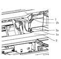
図2は、図1に示すインクジェット記録装置においてカバーユニット1と本体30の接続形態を説明するための図である。図2(a)は、カバーユニット1が本体30に取り付けられた状態を示す斜視図である。図2(b)は、カバーユニット1をその下面(本体30に対向する面)から見た斜視図である。図2(c)は、カバーユニット1が本体30に取り付けられた状態を示す側面図である。 FIG. 2 is a view for explaining a connection form of the
図2(b)に示すように、カバーユニット1の背面には、円柱状の軸部1c、1dが設けられている。軸部1c、1dは、本体30に設けられた軸受部30aに支持されている(図2(c)参照)。カバーユニット1が、軸部1c、1dを中心に回転することによって、本体30の開口31(図1(b)参照)が開閉される。軸部1cの近傍には、先細り形状の突起部材1aと、板状の突起部材1bとが設けられている。 As shown in FIG. 2B,
さらに、図2(b)に示すように、カバーユニット1の下面には、突起1e、1fが設けられている。カバーユニット1が本体30の開口31を閉じているときに突起1e、1fは、本体30に接触している。突起1e、1fによって、カバーユニット1の姿勢が決まる。 Further, as shown in FIG. 2B,
図3は、本体30の要部を示す平面図である。図4は、カバーユニット1と本体30との接続部分を拡大して示す斜視図である。図3に示すように、本体30には、カバーユニット1の開閉動作を検知する検知部20、記録媒体に向けてインクを吐出する記録部32、及びキャリッジ33が内蔵されている。記録部32は、記録媒体の搬送方向に直交する走査方向に往復移動するキャリッジ33に搭載されている。記録部32は、記録媒体に対向する位置に設けられたブラックインク及び複数のカラーインクそれぞれに対応した複数の吐出口を持つ記録ヘッドと、その上に設けられたインクタンクを有する。図3は上方から見た図なので、記録部32として見えているのはインクタンクであり、記録ヘッドはその下に隠れている。なお、記録部32を記録ヘッドだけとしてインクタンクを持たせずに、装置の別の場所に設置されたインクタンクから、チューブを介してキャリッジ33に搭載された記録ヘッドにインクを供給するような形態であってもよい。 FIG. 3 is a plan view showing a main part of the
図3に示すように、記録部32は、後述するフレーム2に形成された内壁部2aを隔てて検知部20と反対側に配置されている。装置が水平に設置されたとき、内壁部2aは、検知部20よりも重力方向に高い位置に配置されている。 As shown in FIG. 3, the
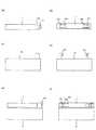
図5は、本体30において検知部20の周辺領域を示す斜視図である。図6は、カバーユニット1の開閉動作を説明するための断面図である。図6(a)は、カバーユニット1が本体30の開口31を開放した開状態を示す。図6(b)は、カバーユニット1が本体30の開口31を閉じた閉状態を示す。図6(a)、(b)では記録部32は図示されていないが、記録部32は内壁部2aの右側に配置されている。 FIG. 5 is a perspective view showing a peripheral region of the
検知部20は、上述した軸受部30aの下側に配置され、樹脂製のフレーム2内に収容されている。本実施形態では、検知部20はリーフスイッチである。検知部20には、リーフスイッチの他にタクティカルスイッチなどのメカスイッチが適用できる。さらに、検知部20にはフォトインタラプタなどの光学スイッチも適用できる。メカスイッチであれ光学スイッチであれ、スイッチの感応部にインクミストが多量に付着すると、センシングの誤動作や故障の原因となり得る。これを抑制するための手段について以下説明する。 The
図6(a)に示す開状態では、検知部20は、カバーユニット1と接触していない。本体30は、インクタンクの交換または紙詰まり処理のためのメンテナンスモードに移行する。インクタンクの交換の場合には、インクタンクを搭載したキャリッジ33が開口31から露出する位置に移動する。メンテナンスモードでは、記録ヘッドはインクを記録媒体に吐出しない。 In the open state shown in FIG. 6A, the
図6(a)に示す開状態から図6(b)に示す閉状態に移行するとき、フレーム2に形成された穴部2bに沿ってカバーユニット1の突起部材1aが下降して検知部20に接触する。検知部20は、突起部材1aによって、図6(a)に示す位置から下側に変位させられる。この変位によって、検知部20は、閉状態であることを検知する。検知部20の検知によって、記録ヘッドはインクを記録媒体に吐出可能な状態となる。図6(b)に示す閉状態では、カバーユニット1に設けられた突起部材1bが、内壁部2aに対して検知部側で平行に対向している。 When shifting from the open state shown in FIG. 6 (a) to the closed state shown in FIG. 6 (b), the protruding
上述した本実施形態のインクジェット記録装置では、記録部32の記録ヘッドからインクを吐出したときに発生したインクミストが、検知部の側へ浮遊する可能性がある。ここで、記録ヘッドと検知部20との間には、検知部20よりも高い位置に配置された内壁部2aが設けられている。この構成により、記録ヘッドで発生したインクミストの多くは、内壁部2aでブロックされる。その結果、検知部20のある空間にインクミストが侵入しにくくなる。 In the ink jet recording apparatus of the present embodiment described above, ink mist generated when ink is ejected from the recording head of the
インクミストの一部は、内壁部2aの上端部とカバーユニット1との隙間から検知部の側へ入り込む可能性がある。しかし、カバーユニット1には、内壁部2aに対して検知部の側で対向する板状の突起部材1bが設けられている。そのため、内壁部2aの上端部とカバーユニット1との隙間から入り込んだインクミストは、突起部材1bにブロックされる。その結果、検知部20のある空間へのインクミスト侵入の抑制効果が向上する。 A part of the ink mist may enter the detection unit side through a gap between the upper end of the
カバーユニット1において突起部材1bは、内壁部2aに対して記録ヘッド側で対向するように設けられていてもよい。この場合、記録ヘッドから発生したインクミストの多くは、突起部材1bでブロックされる。インクミストの一部は、突起部材1bの下端部と本体30との隙間から入り込む可能性がある。しかし、このインクミストは、内壁部2aによってブロックされる。そのため、突起部材1bが内壁部2aに対して検知部側に対向しているのと同様に、インクミストの検知部側への侵入の抑制効果が向上する。 In the
以上のように、カバーユニット1を閉じた閉状態では、内壁部2aによって、検知部20が位置する空間が記録部32の記録ヘッドの側から仕切られる。これにより、検知部20へのインクミスト付着が大幅に減るので、センサの誤動作や故障が大きく抑制される。なお、本明細書において、「仕切られる」とは、隙間なく空間が分離されるとの厳密な意味ではなく、インクミストの侵入を減らす遮蔽効果がある仕切りであれば、多少の隙間がある形態も含む意味である。本発明において「仕切られる」とは上記解釈が適用される。 As described above, in the closed state in which the
さらに、本実施形態のインクジェット記録装置では、開状態において、内壁部2aによってユーザーは開口31から検知部20を直接触ることができない。そのため、ユーザーが紙詰まりを直すときに、ユーザーが誤って検知部20を強く押して検知部20が壊れる事態を回避できるようになる。さらに、本体30に内壁部2aを形成することによって、外部から検知部20までの沿面距離が増える。これにより、検知部20が静電破壊するのを抑制することが可能となる。 Furthermore, in the ink jet recording apparatus of the present embodiment, in the open state, the user cannot directly contact the
図7は、本体30に複数の内壁部2aが形成された形態を示す斜視図である。図7では、複数の内壁部2aが穴部2bを囲むように形成されている。穴部2bの下方に検知部20が配置されている。そのため、検知部20は、複数の内壁部2aに囲まれる。これにより、検知部20が位置する空間はより密閉性が高まるので、インクミスト侵入の抑制効果がより一層向上する。 FIG. 7 is a perspective view showing a form in which a plurality of
(実施形態2)
本発明の実施形態2について説明する。以下、上述した実施形態1と異なる点を中心に説明する。図8は、実施形態2のインクジェット記録装置の要部を示す断面図である。実施形態1で説明した構成要素と同様の構成要素については、同じ符号を付し、詳細な説明を省略する。(Embodiment 2)
A second embodiment of the present invention will be described. Hereinafter, a description will be given focusing on differences from the first embodiment. FIG. 8 is a cross-sectional view illustrating a main part of the ink jet recording apparatus according to the second embodiment. The same components as those described in the first embodiment are denoted by the same reference numerals, and detailed description thereof is omitted.
図8に示すインクジェット記録装置は閉状態である。閉状態では、カバーユニット1に設けられた突起部材1bの下端部が、本体30のフレーム2に接触している。突起部材1bとフレーム2との隙間が実施形態1よりも小さくなるので、ここから検知部20が位置する空間へインクミストが侵入することを、実施形態1よりも確実に抑制できる。 The ink jet recording apparatus shown in FIG. 8 is in a closed state. In the closed state, the lower end portion of the protruding
なお、突起部材1bの下端部がフレーム2に接触する形態に限らず、フレーム2に設けられた内壁部2aの上端部がカバーユニット1に接触する形態であってもよい。あるいは、突起部材1bの下端部、内壁部2aの上端部の両方が接触する形態であってもよい。 In addition, the form which the upper end part of the
実施形態2では、本体30に対してカバーユニット1を開閉可能にするヒンジ機構を有し、ヒンジ機構はカバーユニット1が開口31に対して垂直な方向に移動することができる遊びを持っている。具体的な構造について以下説明する。 The second embodiment has a hinge mechanism that allows the
図9は、図8に示すインクジェット記録装置の側面図である。図9(a)は、装置全体の側面図である。図9(b)は、図9(a)に示す点線部分で囲まれた領域Rの拡大図である。 FIG. 9 is a side view of the ink jet recording apparatus shown in FIG. FIG. 9A is a side view of the entire apparatus. FIG. 9B is an enlarged view of a region R surrounded by a dotted line portion shown in FIG.
図9(b)に示すように、カバーユニット1は、円柱状の軸部1cを有する。軸部1cは、本体30に設けられた軸受部30aに支持されている。軸部1cと軸受部30aによりヒンジ機構が構成されている。軸受部30aには、軸部1cが内接された楕円状の穴部30bを有する。穴部30bの長軸方向は、本体30の開口31(図1(b)参照)の仮想的な面に対して交差する方向(この例では垂直な方向)A(図9(b)の矢印参照)となっている。このヒンジ機構により、カバーユニット1は、軸部1cを中心に回転可能であり、かつ方向Aにも僅かに移動可能な遊びを持っている。 As shown in FIG. 9B, the
本実施形態では、カバーユニット1に設けられた突起部材1bの長さの寸法誤差によって突起部材1bがフレーム2に接触したときに閉状態とならない(カバーユニット1が本体30に対して傾いた状態になる)可能性がある。そこで、軸受部30aの穴部30bで軸部1の位置を微調整する(カバーユニット1を浮かび上がらせる)ことによって、閉状態を確保することができる。なお、軸受部30a自身が上述した方向Aに移動可能な構成であってもよい。 In the present embodiment, when the protruding
図10は、カバーユニット1と本体30の接続に関し、図9に示す形態とは異なる形態を示す図である。図10(a)はカバーユニット1の側面図である。図10(b)はカバーユニット1の背面図である。図10(c)は、本体30の側面図である。図10(d)は、本体30の背面図である。図10(e)は、カバーユニット1が本体30に取り付けられた状態を示す側面図である。図10(f)は、カバーユニット1が本体30に取り付けられた状態を示す背面図である。 FIG. 10 is a diagram showing a form different from the form shown in FIG. 9 with respect to the connection between the
図10(a)、(b)に示すように、カバーユニット1の背面には、軸受部30aと同様の軸受部10aが設けられている。軸受部10aには、楕円状の穴部10bが設けられている。図10(c)、(d)に示すように、本体30の上部には、軸部1cと同様の円柱状の軸部130が設けられている。軸部130と軸受部10aによりヒンジ機構が構成されている。軸部130は、軸受部10aの穴部10bに内接される(図10(f)参照)。このヒンジ機構により、カバーユニット1は、軸部130を中心に回転可能であり、かつ開口41の仮想的な面に対して交差する方向(この例では垂直な方向)にも移動可能な遊びを持っている。その結果、図9に示す構成と同様に、カバーユニット1の位置を調整することが可能となる。 As shown in FIGS. 10A and 10B, a bearing
1 カバーユニット
2a 内壁部
20 検知部
30 本体
32 記録部
33 キャリッジDESCRIPTION OF
Claims (10)
Translated fromJapanese前記記録ヘッドを含む記録部を内部に有し、開口が形成された本体と、
前記開口に対して開閉するカバーユニットと、
前記本体の内部に設けられ、前記カバーユニットの開閉を検知する検知部と、
を有し、
前記本体の内部であって前記検知部と前記記録ヘッドの間には、上端を有する板状の第1壁部が設けられ、かつ前記カバーユニットには、前記カバーユニットから突き出た下端を有する板状の第2壁部と前記検知部の検知のための突起部とが設けられ、
前記検知部は、前記突起部が前記検知部に近づくと前記カバーユニットが前記開口を閉じた閉状態であることを検知するとともに、前記突起部が前記検知部から離れると前記カバーユニットが前記開口を開放した開状態であることを検知し、
前記カバーユニットが前記閉状態のときに、前記本体の内部において前記第1壁部の前記上端が前記第2壁部の前記下端よりも高くなるように前記第1壁部と前記第2壁部が平行に対向して、前記検知部が位置する空間が前記第1壁部と前記第2壁部により前記記録ヘッドの側から仕切られ、
前記カバーユニットが前記開状態のときに、前記第2壁部の前記下端が前記第1壁部の前記上端よりも高くなるように前記第1壁部から前記第2壁部が離れて、前記空間と前記記録ヘッドの側との仕切りが解除されることを特徴とするインクジェット記録装置。A recording head for ejecting ink;
A main body having arecording portion including the recording headtherein and having an opening formed therein;
A cover unit that opens and closes relative to the opening;
A detection unitthat is provided inside the main body and detects opening and closing of the cover unit;
Have
Between internaland a said detectionunit and the recording head of thebody, the first wall portiona plate-shapedis providedhaving anupper,and the cover unit, the plate having a projecting lower end from the cover unit A second wall portion having a shape and a protrusion for detection of the detection portion ,
The detection unit detects that the cover unit is in a closed state in which the opening is closed when the projection approaches the detection unit, and the cover unit opens when the projection is separated from the detection unit. Is detected to be open,
The first wall portion and the second wall portion so that the upper end of the first wall portion is higher than the lower end of the second wall portion inside the main bodywhen the cover unitis in the closed state.Are opposed to each other in parallel, and a spacein which the detection unit is located is partitioned from the recording head sideby the first wall portion and the second wall portion,
When the cover unit is in the open state, the second wall is separated from the first wall so that the lower end of the second wall is higher than the upper end of the first wall, An ink jet recording apparatus, wherein the partition between the space and the recording head side is released .
Priority Applications (3)
| Application Number | Priority Date | Filing Date | Title |
|---|---|---|---|
| JP2012151461AJP6045227B2 (en) | 2012-07-05 | 2012-07-05 | Inkjet recording device |
| US13/930,333US8955967B2 (en) | 2012-07-05 | 2013-06-28 | Printing apparatus with an openable cover structure |
| CN201310279319.8ACN103522755B (en) | 2012-07-05 | 2013-07-04 | Printing apparatus |
Applications Claiming Priority (1)
| Application Number | Priority Date | Filing Date | Title |
|---|---|---|---|
| JP2012151461AJP6045227B2 (en) | 2012-07-05 | 2012-07-05 | Inkjet recording device |
Publications (2)
| Publication Number | Publication Date |
|---|---|
| JP2014012389A JP2014012389A (en) | 2014-01-23 |
| JP6045227B2true JP6045227B2 (en) | 2016-12-14 |
Family
ID=49878235
Family Applications (1)
| Application Number | Title | Priority Date | Filing Date |
|---|---|---|---|
| JP2012151461AExpired - Fee RelatedJP6045227B2 (en) | 2012-07-05 | 2012-07-05 | Inkjet recording device |
Country Status (3)
| Country | Link |
|---|---|
| US (1) | US8955967B2 (en) |
| JP (1) | JP6045227B2 (en) |
| CN (1) | CN103522755B (en) |
Families Citing this family (3)
| Publication number | Priority date | Publication date | Assignee | Title |
|---|---|---|---|---|
| JP6029359B2 (en)* | 2012-07-09 | 2016-11-24 | キヤノン株式会社 | Image forming apparatus and carriage fixing method |
| US10606578B2 (en)* | 2015-10-23 | 2020-03-31 | Oracle International Corporation | Provisioning of pluggable databases using a central repository |
| JP7257856B2 (en)* | 2019-04-05 | 2023-04-14 | キヤノン株式会社 | recording device |
Family Cites Families (17)
| Publication number | Priority date | Publication date | Assignee | Title |
|---|---|---|---|---|
| JP2524158Y2 (en)* | 1990-06-19 | 1997-01-29 | セイコーエプソン株式会社 | Printer cover safety switch structure |
| JP3873327B2 (en) | 1996-08-19 | 2007-01-24 | ブラザー工業株式会社 | Inkjet printer with replaceable ink cartridge |
| JP2001345566A (en)* | 2000-05-31 | 2001-12-14 | Kyocera Mita Corp | Safety device for electronic equipment apparatus |
| US20050146591A1 (en)* | 2004-01-07 | 2005-07-07 | Matsushita Electric Industrial Co., Ltd. | Recording apparatus |
| JP2005205647A (en)* | 2004-01-21 | 2005-08-04 | Matsushita Electric Ind Co Ltd | Recording apparatus |
| US7448734B2 (en)* | 2004-01-21 | 2008-11-11 | Silverbrook Research Pty Ltd | Inkjet printer cartridge with pagewidth printhead |
| JP2006012590A (en)* | 2004-06-25 | 2006-01-12 | Kyocera Mita Corp | Opening/closing detector |
| JP2006080863A (en)* | 2004-09-09 | 2006-03-23 | Canon Inc | Image reading and recording device |
| JP2007015246A (en) | 2005-07-08 | 2007-01-25 | Canon Inc | Recording device |
| JP5000876B2 (en)* | 2005-10-05 | 2012-08-15 | 株式会社リコー | Open / close detection mechanism and image forming apparatus |
| US7914218B2 (en)* | 2006-06-29 | 2011-03-29 | Toshiba Tec Kabushiki Kaisha | Thermal printer and printing device |
| JP5039404B2 (en)* | 2007-03-26 | 2012-10-03 | キヤノン株式会社 | Image forming apparatus |
| JP5066017B2 (en) | 2008-07-02 | 2012-11-07 | 株式会社リコー | Image forming apparatus |
| JP5187076B2 (en)* | 2008-08-27 | 2013-04-24 | セイコーエプソン株式会社 | Open / close judgment of device opening |
| JP5187077B2 (en) | 2008-08-27 | 2013-04-24 | セイコーエプソン株式会社 | Open / close judgment of device opening |
| JP2011051265A (en)* | 2009-09-02 | 2011-03-17 | Fujitsu Component Ltd | Portable printer |
| JP5835653B2 (en)* | 2011-08-30 | 2015-12-24 | ブラザー工業株式会社 | Printing device |
- 2012
- 2012-07-05JPJP2012151461Apatent/JP6045227B2/ennot_activeExpired - Fee Related
- 2013
- 2013-06-28USUS13/930,333patent/US8955967B2/ennot_activeExpired - Fee Related
- 2013-07-04CNCN201310279319.8Apatent/CN103522755B/ennot_activeExpired - Fee Related
Also Published As
| Publication number | Publication date |
|---|---|
| US20140009553A1 (en) | 2014-01-09 |
| CN103522755B (en) | 2015-06-17 |
| US8955967B2 (en) | 2015-02-17 |
| CN103522755A (en) | 2014-01-22 |
| JP2014012389A (en) | 2014-01-23 |
Similar Documents
| Publication | Publication Date | Title |
|---|---|---|
| US12076998B2 (en) | Liquid jetting apparatus | |
| JP6874313B2 (en) | Printing fluid containment device, printing fluid supply device, and adapter | |
| JP7287112B2 (en) | recording device | |
| JP2013129178A (en) | Printing fluid cartridge | |
| JP6045227B2 (en) | Inkjet recording device | |
| JP2010228374A (en) | Ink supply device | |
| US20240059086A1 (en) | Recording apparatus | |
| JP7655139B2 (en) | Liquid cartridge and liquid consumption device | |
| JP2010228377A (en) | Ink supply device | |
| JP6961918B2 (en) | Printing fluid containment device, printing fluid supply device, and adapter | |
| JP6819066B2 (en) | Printing fluid cartridge | |
| CA3094211C (en) | Liquid cartridge | |
| JP6145995B2 (en) | Additional discharge tray and image recording apparatus | |
| JP5924260B2 (en) | Recording device | |
| JP7658210B2 (en) | Liquid cartridge and liquid consumption device | |
| JP5408174B2 (en) | Recording device | |
| JP5195579B2 (en) | Ink supply device | |
| JP2023144793A (en) | liquid cartridge | |
| JP2013141808A (en) | Recorder | |
| JP2008062530A (en) | Housing structure, recording apparatus and electronic apparatus |
Legal Events
| Date | Code | Title | Description |
|---|---|---|---|
| RD04 | Notification of resignation of power of attorney | Free format text:JAPANESE INTERMEDIATE CODE: A7424 Effective date:20140430 | |
| A621 | Written request for application examination | Free format text:JAPANESE INTERMEDIATE CODE: A621 Effective date:20150602 | |
| A977 | Report on retrieval | Free format text:JAPANESE INTERMEDIATE CODE: A971007 Effective date:20160314 | |
| A131 | Notification of reasons for refusal | Free format text:JAPANESE INTERMEDIATE CODE: A131 Effective date:20160322 | |
| A521 | Request for written amendment filed | Free format text:JAPANESE INTERMEDIATE CODE: A523 Effective date:20160520 | |
| TRDD | Decision of grant or rejection written | ||
| A01 | Written decision to grant a patent or to grant a registration (utility model) | Free format text:JAPANESE INTERMEDIATE CODE: A01 Effective date:20161018 | |
| A61 | First payment of annual fees (during grant procedure) | Free format text:JAPANESE INTERMEDIATE CODE: A61 Effective date:20161115 | |
| R151 | Written notification of patent or utility model registration | Ref document number:6045227 Country of ref document:JP Free format text:JAPANESE INTERMEDIATE CODE: R151 | |
| LAPS | Cancellation because of no payment of annual fees |