JP6044961B2 - Spine brake - Google Patents
Spine brakeDownload PDFInfo
- Publication number
- JP6044961B2 JP6044961B2JP2013521603AJP2013521603AJP6044961B2JP 6044961 B2JP6044961 B2JP 6044961B2JP 2013521603 AJP2013521603 AJP 2013521603AJP 2013521603 AJP2013521603 AJP 2013521603AJP 6044961 B2JP6044961 B2JP 6044961B2
- Authority
- JP
- Japan
- Prior art keywords
- covering portion
- covering
- side member
- vertebral arch
- vertebra
- Prior art date
- Legal status (The legal status is an assumption and is not a legal conclusion. Google has not performed a legal analysis and makes no representation as to the accuracy of the status listed.)
- Active
Links
- 210000001217buttockAnatomy0.000claimsdescription58
- 239000000843powderSubstances0.000claimsdescription12
- 238000005245sinteringMethods0.000claimsdescription12
- 238000004519manufacturing processMethods0.000claimsdescription11
- 230000002138osteoinductive effectEffects0.000claimsdescription11
- 239000011159matrix materialSubstances0.000claimsdescription8
- 239000011248coating agentSubstances0.000description24
- 238000000576coating methodMethods0.000description24
- 210000000988bone and boneAnatomy0.000description23
- 238000000034methodMethods0.000description20
- 239000000463materialSubstances0.000description11
- 239000010936titaniumSubstances0.000description8
- 239000000654additiveSubstances0.000description7
- 230000000996additive effectEffects0.000description7
- 238000005520cutting processMethods0.000description7
- 239000000126substanceSubstances0.000description7
- RTAQQCXQSZGOHL-UHFFFAOYSA-NTitaniumChemical compound[Ti]RTAQQCXQSZGOHL-UHFFFAOYSA-N0.000description6
- 230000010478bone regenerationEffects0.000description6
- 238000002591computed tomographyMethods0.000description6
- 230000003902lesionEffects0.000description6
- 230000001737promoting effectEffects0.000description6
- 229910052719titaniumInorganic materials0.000description6
- 210000001015abdomenAnatomy0.000description5
- 239000000758substrateSubstances0.000description5
- 102000007350Bone Morphogenetic ProteinsHuman genes0.000description4
- 108010007726Bone Morphogenetic ProteinsProteins0.000description4
- 229910001069Ti alloyInorganic materials0.000description4
- 229940112869bone morphogenetic proteinDrugs0.000description4
- 210000005069earsAnatomy0.000description4
- 238000003475laminationMethods0.000description4
- 238000002595magnetic resonance imagingMethods0.000description4
- 238000005259measurementMethods0.000description4
- 238000000465mouldingMethods0.000description4
- 230000011164ossificationEffects0.000description4
- QORWJWZARLRLPR-UHFFFAOYSA-Htricalcium bis(phosphate)Chemical compound[Ca+2].[Ca+2].[Ca+2].[O-]P([O-])([O-])=O.[O-]P([O-])([O-])=OQORWJWZARLRLPR-UHFFFAOYSA-H0.000description4
- 230000004927fusionEffects0.000description3
- 239000007943implantSubstances0.000description3
- 230000006698inductionEffects0.000description3
- 238000003780insertionMethods0.000description3
- 230000037431insertionEffects0.000description3
- 238000012545processingMethods0.000description3
- 210000000115thoracic cavityAnatomy0.000description3
- TWDJIKFUVRYBJF-UHFFFAOYSA-NCyanthoateChemical compoundCCOP(=O)(OCC)SCC(=O)NC(C)(C)C#NTWDJIKFUVRYBJF-UHFFFAOYSA-N0.000description2
- 239000004698PolyethyleneSubstances0.000description2
- 206010041591Spinal osteoarthritisDiseases0.000description2
- WAIPAZQMEIHHTJ-UHFFFAOYSA-N[Cr].[Co]Chemical class[Cr].[Co]WAIPAZQMEIHHTJ-UHFFFAOYSA-N0.000description2
- 239000000853adhesiveSubstances0.000description2
- 230000001070adhesive effectEffects0.000description2
- 239000012237artificial materialSubstances0.000description2
- 239000000919ceramicSubstances0.000description2
- 230000007547defectEffects0.000description2
- 230000003412degenerative effectEffects0.000description2
- 238000010586diagramMethods0.000description2
- 210000004177elastic tissueAnatomy0.000description2
- 238000011049fillingMethods0.000description2
- 229910052588hydroxylapatiteInorganic materials0.000description2
- 238000003384imaging methodMethods0.000description2
- 230000001939inductive effectEffects0.000description2
- 229910052751metalInorganic materials0.000description2
- 239000002184metalSubstances0.000description2
- 230000001575pathological effectEffects0.000description2
- 230000000149penetrating effectEffects0.000description2
- XYJRXVWERLGGKC-UHFFFAOYSA-Dpentacalcium;hydroxide;triphosphateChemical compound[OH-].[Ca+2].[Ca+2].[Ca+2].[Ca+2].[Ca+2].[O-]P([O-])([O-])=O.[O-]P([O-])([O-])=O.[O-]P([O-])([O-])=OXYJRXVWERLGGKC-UHFFFAOYSA-D0.000description2
- -1polyethylenePolymers0.000description2
- 229920000573polyethylenePolymers0.000description2
- 238000002360preparation methodMethods0.000description2
- 208000005801spondylosisDiseases0.000description2
- 239000010935stainless steelSubstances0.000description2
- 229910001220stainless steelInorganic materials0.000description2
- 210000001519tissueAnatomy0.000description2
- 208000003618Intervertebral Disc DisplacementDiseases0.000description1
- 208000028389Nerve injuryDiseases0.000description1
- 208000007103SpondylolisthesisDiseases0.000description1
- 230000003187abdominal effectEffects0.000description1
- 238000012925biological evaluationMethods0.000description1
- 210000004204blood vesselAnatomy0.000description1
- 210000002805bone matrixAnatomy0.000description1
- 238000007796conventional methodMethods0.000description1
- 238000013016dampingMethods0.000description1
- 201000010099diseaseDiseases0.000description1
- 208000037265diseases, disorders, signs and symptomsDiseases0.000description1
- 239000000017hydrogelSubstances0.000description1
- 230000001788irregularEffects0.000description1
- 230000008764nerve damageEffects0.000description1
- 230000002188osteogenic effectEffects0.000description1
- 230000008929regenerationEffects0.000description1
- 238000011069regeneration methodMethods0.000description1
- 206010039722scoliosisDiseases0.000description1
- 238000004088simulationMethods0.000description1
- 208000020431spinal cord injuryDiseases0.000description1
- 210000000130stem cellAnatomy0.000description1
- 230000001954sterilising effectEffects0.000description1
- 238000004659sterilization and disinfectionMethods0.000description1
- 238000001356surgical procedureMethods0.000description1
Images


Classifications
- A—HUMAN NECESSITIES
- A61—MEDICAL OR VETERINARY SCIENCE; HYGIENE
- A61B—DIAGNOSIS; SURGERY; IDENTIFICATION
- A61B17/00—Surgical instruments, devices or methods
- A61B17/56—Surgical instruments or methods for treatment of bones or joints; Devices specially adapted therefor
- A61B17/58—Surgical instruments or methods for treatment of bones or joints; Devices specially adapted therefor for osteosynthesis, e.g. bone plates, screws or setting implements
- A61B17/68—Internal fixation devices, including fasteners and spinal fixators, even if a part thereof projects from the skin
- A61B17/70—Spinal positioners or stabilisers, e.g. stabilisers comprising fluid filler in an implant
- A61B17/7062—Devices acting on, attached to, or simulating the effect of, vertebral processes, vertebral facets or ribs ; Tools for such devices
- A61B17/7068—Devices comprising separate rigid parts, assembled in situ, to bear on each side of spinous processes; Tools therefor
- A—HUMAN NECESSITIES
- A61—MEDICAL OR VETERINARY SCIENCE; HYGIENE
- A61B—DIAGNOSIS; SURGERY; IDENTIFICATION
- A61B17/00—Surgical instruments, devices or methods
- A61B17/56—Surgical instruments or methods for treatment of bones or joints; Devices specially adapted therefor
- A61B17/58—Surgical instruments or methods for treatment of bones or joints; Devices specially adapted therefor for osteosynthesis, e.g. bone plates, screws or setting implements
- A61B17/68—Internal fixation devices, including fasteners and spinal fixators, even if a part thereof projects from the skin
- A61B17/80—Cortical plates, i.e. bone plates; Instruments for holding or positioning cortical plates, or for compressing bones attached to cortical plates
- A61B17/8085—Cortical plates, i.e. bone plates; Instruments for holding or positioning cortical plates, or for compressing bones attached to cortical plates with pliable or malleable elements or having a mesh-like structure, e.g. small strips
- A—HUMAN NECESSITIES
- A61—MEDICAL OR VETERINARY SCIENCE; HYGIENE
- A61B—DIAGNOSIS; SURGERY; IDENTIFICATION
- A61B17/00—Surgical instruments, devices or methods
- A61B17/56—Surgical instruments or methods for treatment of bones or joints; Devices specially adapted therefor
- A61B2017/568—Surgical instruments or methods for treatment of bones or joints; Devices specially adapted therefor produced with shape and dimensions specific for an individual patient
- A—HUMAN NECESSITIES
- A61—MEDICAL OR VETERINARY SCIENCE; HYGIENE
- A61B—DIAGNOSIS; SURGERY; IDENTIFICATION
- A61B34/00—Computer-aided surgery; Manipulators or robots specially adapted for use in surgery
- A61B34/10—Computer-aided planning, simulation or modelling of surgical operations
- A61B2034/108—Computer aided selection or customisation of medical implants or cutting guides
- A—HUMAN NECESSITIES
- A61—MEDICAL OR VETERINARY SCIENCE; HYGIENE
- A61F—FILTERS IMPLANTABLE INTO BLOOD VESSELS; PROSTHESES; DEVICES PROVIDING PATENCY TO, OR PREVENTING COLLAPSING OF, TUBULAR STRUCTURES OF THE BODY, e.g. STENTS; ORTHOPAEDIC, NURSING OR CONTRACEPTIVE DEVICES; FOMENTATION; TREATMENT OR PROTECTION OF EYES OR EARS; BANDAGES, DRESSINGS OR ABSORBENT PADS; FIRST-AID KITS
- A61F2/00—Filters implantable into blood vessels; Prostheses, i.e. artificial substitutes or replacements for parts of the body; Appliances for connecting them with the body; Devices providing patency to, or preventing collapsing of, tubular structures of the body, e.g. stents
- A61F2/02—Prostheses implantable into the body
- A61F2/30—Joints
- A61F2/44—Joints for the spine, e.g. vertebrae, spinal discs
- A61F2002/449—Joints for the spine, e.g. vertebrae, spinal discs comprising multiple spinal implants located in different intervertebral spaces or in different vertebrae
Landscapes
- Health & Medical Sciences (AREA)
- Orthopedic Medicine & Surgery (AREA)
- Life Sciences & Earth Sciences (AREA)
- Neurology (AREA)
- Surgery (AREA)
- Heart & Thoracic Surgery (AREA)
- Engineering & Computer Science (AREA)
- Biomedical Technology (AREA)
- Nuclear Medicine, Radiotherapy & Molecular Imaging (AREA)
- Medical Informatics (AREA)
- Molecular Biology (AREA)
- Animal Behavior & Ethology (AREA)
- General Health & Medical Sciences (AREA)
- Public Health (AREA)
- Veterinary Medicine (AREA)
- Prostheses (AREA)
- Surgical Instruments (AREA)
Description
Translated fromJapanese本発明は、脊椎の動きを制御可能な脊椎制動具に関する。 The present invention relates to a spine brake that can control the movement of the spine.
変形性脊椎症、側弯症、脊椎損傷など、脊椎の不安定性や変形を伴う疾患では、チタン製インプラントを用いた脊椎固定術が広く行われている。脊椎固定術とは、チタン製インプラントなどを脊椎に刺入あるいは固定し、脊椎を固定して安定性を高める手術である。 Spinal fusion using titanium implants is widely used for diseases involving instability and deformation of the spine, such as degenerative spondylosis, scoliosis, and spinal cord injury. Spinal fusion is an operation in which a titanium implant or the like is inserted or fixed in the spine to fix the spine and improve stability.
脊椎を固定する道具としては、例えば、特許文献1に記載されている装置がある。特許文献1には、脊椎ロッド、該脊椎ロッドを胸椎又は腰椎などの椎骨に固定するための脊椎フックや骨ネジなどを備えた、脊椎を矯正して固定するための装置が記載されている。 As a tool for fixing the spine, for example, there is an apparatus described in
脊椎固定術において特に問題となるのは、インプラントの1種である脊椎固定スクリューを脊椎に刺入するときの刺入場所の誤りによる血管や神経の損傷である。また、脊椎を固定することにより、隣接する椎間に力学的ストレスを生じ、新たな病変(隣接椎間病変と呼ばれ、例えば、脊椎すべり症、変形性脊椎症や椎間板ヘルニアなどがある。)を生じる虞があるという問題もある。また、脊椎固定スクリューを必須とする従来の技術は、個々の椎骨をモクネジのような構造で固定する技術であり、術後に該脊椎固定スクリューが引き抜ける虞があった。上記特許文献1に記載された技術においても、骨ネジを脊椎に刺入しており、上記問題と同様の問題が生じ得る。 Particularly problematic in spinal fusion is blood vessel and nerve damage due to an incorrect insertion place when a spinal fixation screw, which is a kind of implant, is inserted into the spine. Also, by fixing the spine, mechanical stress is generated between adjacent vertebrae, and new lesions (called adjacent intervertebral lesions, such as spondylolisthesis, degenerative spondylosis, and disc herniation). There is also a problem that there is a risk of causing. Further, the conventional technique requiring a spinal fixation screw is a technique for fixing individual vertebrae with a structure like a mock screw, and there is a possibility that the spinal fixation screw may be pulled out after the operation. In the technique described in
そこで、本発明は、脊椎の動きを制御可能であり、安全性が向上された脊椎制動具を提供することを課題とする。 Accordingly, an object of the present invention is to provide a spine brake that can control the movement of the spine and has improved safety.
以下、本発明について説明する。 The present invention will be described below.
本発明は、複数の椎骨に装着して脊椎の動きを制御可能な脊椎制動具であって、複数の椎骨の夫々について、該椎骨が有する椎弓の少なくとも一部を覆うことで該椎骨に固定可能な被覆部と、隣り合う被覆部の相対的位置を変更可能に隣り合う被覆部を連結する関節部と、を備えており、被覆部は夫々密着面を有する2つ以上の部材を備えており、密着面は椎弓の表面形状と雄雌の関係の形状を有して椎弓に密着可能な面である、脊椎制動具である。 The present invention relates to a spine brake that can be attached to a plurality of vertebrae to control the movement of the spine, and each of the plurality of vertebrae is fixed to the vertebrae by covering at least a part of the vertebral arch of the vertebrae. And a joint portion that connects the adjacent covering portions so that the relative positions of the adjacent covering portions can be changed. The covering portion includes two or more members each having a close contact surface. The close contact surface is a spinal brake device that has a shape related to the surface shape of the vertebral arch and a male and female and can be in close contact with the vertebral arch.
本発明において「関節部」とは、隣り合う被覆部の相対的位置を適度に変更可能となる可動性を有して、該隣り合う被覆部を連結する部分を意味している。ここで「適度に変更可能となる可動性」とは、本発明の脊椎制動具を用いる際に、患者の病状などに応じて適宜決定することができる程度の可動性を意味している。すなわち、病的意義のある不安定性を解消しつつ、かつ隣接椎間に過剰な力学的ストレスがかからない程度の可動性を有することを意味する。例えば、病状に応じて関節部の可動域を調節あるいは固定することもできる。このような関節部の関節は、例えば、金属、セラミック、あるいはポリエチレンに代表される人工素材で作製することが可能である。また、1個の関節部は、1個あるいは複数の関節を組み合わせて構成することができる。また、「密着面は椎弓の表面形状と雄雌の関係の形状を有して椎弓に密着可能な面である」とは、密着面が椎弓の表面の凹凸形状に精密に一致するように成形された面であることを意味する。このような密着面は、CT(コンピューター断層撮影)を用いて椎弓の立体形状データを取得し、当該データの凹凸形状に精密に一致するようにして成形することができる。ここで「精密に一致する」とは、椎弓の凹凸形状に密着面を実際に密着させた場合に、密着面の80%以上、より好ましくは90%以上、さらに好ましくは95%以上が椎弓と接していること、又は、椎弓の形状と密着面の形状との誤差が2mm以下であることを意味する。なお、複数の椎骨がそれぞれ有する椎弓は、それぞれ異なった表面形状を有している。よって、密着面の形状は被覆部毎に異なっている。 In the present invention, the “joint portion” means a portion that has the mobility that allows the relative position of the adjacent covering portions to be appropriately changed and connects the adjacent covering portions. Here, “mobility that can be changed moderately” means mobility that can be appropriately determined according to a patient's medical condition or the like when the spinal brake device of the present invention is used. In other words, it means that the instability having a pathological significance is eliminated and the mobility is such that excessive mechanical stress is not applied between adjacent vertebrae. For example, the range of motion of the joint can be adjusted or fixed according to the medical condition. Such a joint of the joint portion can be made of, for example, an artificial material typified by metal, ceramic, or polyethylene. In addition, one joint portion can be configured by combining one or a plurality of joints. In addition, “the close contact surface is a surface that has a relationship between the surface shape of the vertebral arch and the male and female and can be in close contact with the vertebral arch” means that the close contact surface precisely matches the concavo-convex shape of the surface of the vertebral arch. It means that the surface is shaped like this. Such a close contact surface can be formed by acquiring three-dimensional shape data of a vertebral arch using CT (computer tomography) and precisely matching the uneven shape of the data. Here, “precisely matches” means that 80% or more, more preferably 90% or more, more preferably 95% or more of the contact surface when the contact surface is actually brought into close contact with the concave and convex shape of the vertebral vertebra. It means that it is in contact with the arch, or the error between the shape of the vertebral arch and the shape of the contact surface is 2 mm or less. In addition, the vertebral arch which each of several vertebrae has has a different surface shape, respectively. Therefore, the shape of the contact surface is different for each covering portion.
本発明の脊椎制動具において、被覆部が2つの部材を備えており、該2つの部材で椎弓を挟むことによって椎骨に固定可能であることが好ましい。 In the spinal brake device of the present invention, it is preferable that the covering portion includes two members, and the vertebra can be fixed to the vertebra by sandwiching the vertebral arch between the two members.
ここに、「被覆部が2つの部材を備えており、該2つの部材で椎弓を挟むことによって椎骨に固定可能である」とは、脊椎制動具に備えられる複数の被覆部のうち少なくとも一つの被覆部が2つの部材を備えており、該2つの部材で椎弓を挟むことによって椎骨に固定可能であることを意味する。かかる形態とすることによって、被覆部によって椎弓の少なくとも一部を覆うことで被覆部を椎骨に固定することが容易になる。 Here, “the covering portion includes two members and can be fixed to the vertebra by sandwiching the vertebral arch between the two members” means that at least one of the plurality of covering portions provided in the spinal brake device. It means that one covering portion includes two members and can be fixed to the vertebra by sandwiching the vertebral arch between the two members. By adopting such a configuration, it becomes easy to fix the covering portion to the vertebra by covering at least a part of the vertebral arch with the covering portion.
また、本発明の脊椎制動具において、隣り合う被覆部のうち頭部側の被覆部が、椎弓の頭部側を覆う第1の頭部側部材と、椎弓の臀部側を覆う第1の臀部側部材とを備え、隣り合う被覆部のうち臀部側の被覆部が、椎弓の頭部側を覆う第2の頭部側部材と、椎弓の臀部側を覆う第2の臀部側部材とを備え、第1の臀部側部材と第2の頭部側部材と第1の臀部側部材及び第2の頭部側部材を連結する関節部とが一体化されていることが好ましい。 Further, in the spinal brake device according to the present invention, the covering portion on the head side among the adjacent covering portions is a first head side member that covers the head side of the vertebral arch, and a first that covers the buttocks side of the vertebral arch. A second head side member that covers the head side of the vertebral arch, and a second buttock side that covers the buttock side of the vertebral arch It is preferable that the 1st buttocks side member, the 2nd head side member, and the joint part which connects the 1st buttocks side member and the 2nd head side member are integrated.
ここに、「隣り合う被覆部のうち頭部側の被覆部が、椎弓の頭部側を覆う第1の頭部側部材と、椎弓の臀部側を覆う第1の臀部側部材とを備え、隣り合う被覆部のうち臀部側の被覆部が、椎弓の頭部側を覆う第2の頭部側部材と、椎弓の臀部側を覆う第2の臀部側部材とを備え」とは、脊椎制動具に備えられる複数の被覆部のうち、少なくとも隣り合う一組の被覆部のうち、頭部側の被覆部が椎弓の頭部側を覆う第1の頭部側部材と椎弓の臀部側を覆う第1の臀部側部材とを備え、臀部側の被覆部が椎弓の頭部側を覆う第2の頭部側部材と椎弓の臀部側を覆う第2の臀部側部材とを備えていることを意味する。このような形態において、第1の臀部側部材と第2の頭部側部材と関節部とが一体化されていることによって、被覆部を椎骨に着脱することが容易になるとともに、被覆部を関節部で連結することが容易になる。 Here, “the first head side member that covers the head side of the vertebral arch and the first buttock side member that covers the buttock side of the vertebral arch” A covering portion on the buttocks side of the adjacent covering portions includes a second head side member that covers the head side of the vertebral arch and a second buttocks side member that covers the buttocks side of the vertebral arch ” The first head-side member and the vertebrae in which the cover portion on the head side covers the head side of the vertebral arch among at least a pair of adjacent cover portions provided in the spinal brake device. A first buttock side member covering the buttock side of the arch, and a second head side member covering the buttock side of the vertebral arch with a second headside member covering the head side of the vertebral arch with a covering portion on the buttock side It means that it is provided with a member. In such a form, since the first buttocks side member, the second head side member, and the joint portion are integrated, the covering portion can be easily attached to and detached from the vertebrae, and the covering portion is It becomes easy to connect at the joint.
また、本発明の脊椎制動具において、被覆部の夫々が、椎弓の頭部側を覆う頭部側部材と椎弓の臀部側を覆う臀部側部材とを備えており、被覆部が固定される椎骨のうち最も頭部側の椎骨に固定可能な被覆部を第1の被覆部とし、被覆部が固定される椎骨のうち頭部側からn番目(ただし、nは2以上の自然数)の椎骨に固定可能な被覆部を第nの被覆部としたとき、第n’の被覆部(ただし、n’は1からn−1までの自然数。)に備えられる臀部側部材と、第n’+1の被覆部に備えられる頭部側部材と、第n’の被覆部に備えられる臀部側部材及び第n’+1の被覆部に備えられる頭部側部材を連結する関節部とが一体化されていることが好ましい。 In the spinal brake device of the present invention, each of the covering portions includes a head side member that covers the head side of the vertebral arch and a buttock side member that covers the buttocks side of the vertebral arch, and the covering portion is fixed. The covering portion that can be fixed to the vertebra on the most head side among the vertebrae is the first covering portion, and the nth from the head side among the vertebrae to which the covering portion is fixed (where n is a natural number of 2 or more) When the covering portion fixable to the vertebra is the n-th covering portion, the buttocks side member provided in the n′-th covering portion (where n ′ is a natural number from 1 to n−1), and the n′-th covering portion The head-side member provided in the +1 covering portion, the joint-side member provided in the n'th covering portion, and the joint portion connecting the head-side member provided in the n '+ 1 covering portion are integrated. It is preferable.
脊椎制動具に備えられる全ての被覆部が、椎弓の頭部側を覆う頭部側部材と椎弓の臀部側を覆う臀部側部材とを備えており、隣り合う全ての被覆部において、一方の被覆部の臀部側部材と他方の被覆部の頭部側部材と該臀部側部材及び該頭部側部材を連結する関節部とが一体化されていることによって、被覆部の数が多い場合であっても、夫々の被覆部を椎骨に着脱することが容易になるとともに、それらの被覆部を関節部で連結することが容易になる。 All of the covering parts provided in the spinal brake are provided with a head side member that covers the head side of the vertebral arch and a buttocks side member that covers the buttock side of the vertebral arch. When the number of covering parts is large by integrating the collar side member of the covering part, the head side member of the other covering part, and the joint part connecting the collar side member and the head side member. Even so, it is easy to attach and detach the respective covering portions to the vertebrae, and it is easy to connect these covering portions at the joint portions.
また、本発明の脊椎制動具において、被覆部と関節部とが別々に成形されており、被覆部に対して関節部を着脱可能である形態も好ましい。 Further, in the spinal brake device of the present invention, it is also preferable that the covering portion and the joint portion are formed separately and the joint portion can be attached to and detached from the covering portion.
被覆部と関節部とが別々に成形されていることによって、まず椎骨に被覆部を固定した後、隣り合う被覆部を関節部で連結することができる。例えば、独立して成形された複数の被覆部を夫々の椎骨に固定し、所定の期間が経過して自家骨により該被覆部が椎骨に恒久的に固定された後、隣り合う被覆部を関節部で連結することができる。 Since the covering portion and the joint portion are separately molded, the covering portion is first fixed to the vertebra, and then the adjacent covering portions can be connected by the joint portion. For example, a plurality of independently formed covering portions are fixed to each vertebra, and after a predetermined period of time, the covering portions are permanently fixed to the vertebra by autologous bone, and then adjacent covering portions are jointed. It can be connected at the part.
また、本発明の脊椎制動具において、被覆部の密着面を含む部分において、メッシュ状又はスポンジ状に成形された部分を有することが好ましい。 In the spinal brake device of the present invention, it is preferable that the portion including the close contact surface of the covering portion has a portion formed in a mesh shape or a sponge shape.
ここに、「メッシュ状」とは、被覆部のうち該被覆部が覆う椎弓側の面(密着面)から反対側の面へと貫通した孔を複数有する構造を意味している。また、「スポンジ状」とは、被覆部の内部に微細な空洞が複数成形された構造を意味し、これらの空洞が不規則に連続した構造を有していてもよい。このようなメッシュ状又はスポンジ状に成形された部分を有する形態とすることによって、被覆部の密着面に微細な凸凹が成形されることになり、被覆部を椎弓に取り付けた際の固定性が良くなる。 Here, the “mesh shape” means a structure having a plurality of holes penetrating from the surface on the vertebral arch side (contact surface) covered by the covering portion to the opposite surface of the covering portion. Further, the “sponge” means a structure in which a plurality of fine cavities are formed inside the covering portion, and these cavities may have an irregularly continuous structure. By adopting a form having such a mesh-shaped or sponge-shaped part, fine irregularities are formed on the adhesion surface of the covering part, and the fixing property when the covering part is attached to the vertebral arch Will be better.
また、本発明の脊椎制動具において、被覆部が、密着面及びメッシュ状又はスポンジ状に成形された部分に骨誘導基質を備えていることが好ましい。 In the spinal brake device of the present invention, it is preferable that the covering portion is provided with an osteoinductive matrix in the contact surface and a portion formed in a mesh shape or a sponge shape.
ここに、「密着面に骨誘導基質を備えている」とは、密着面の表面に骨誘導基質を含む層が成形されていることを意味する。また、「メッシュ状又はスポンジ状に成形された部分に骨誘導基質を備えている」とは、メッシュ状の構造を構成する貫通孔の表面若しくは内部、又はスポンジ状の構造を構成する空洞の表面若しくは内部に、骨誘導基質を備えていることを意味する。また、「骨誘導基質」とは、骨再生誘導作用を有する、骨補填材あるいは骨再生促進物質を意味する。「骨補填材」としては、日本ですでに医療機器として承認されている骨欠損部に使用される材料であって、自家骨とほぼ同じ成分で徐々に自家骨と融合して一体化するもの(例えば、ハイドロキシアパタイトなど)、あるいは自家骨に置換されるもの(例えば、ベータリン酸三カルシウム(bTCP)など)が知られている。また、「骨再生促進物質」としては、骨形成を促進する作用のある物質で、骨形成蛋白(bone morphogenetic protein(BMP))などが知られている。被覆部の密着面及びメッシュ状又はスポンジ状に成形された部分に骨誘導基質を備えている形態とすれば、該骨誘導基質の作用によって被覆部の表面に骨形成が起こり、被覆部と椎骨とを一体化させて恒久的に固定することが容易になる。 Here, “having an osteoinductive substrate on the close contact surface” means that a layer containing the osteoinductive substrate is formed on the surface of the close contact surface. In addition, “the part formed in a mesh shape or a sponge shape is provided with an osteoinductive matrix” means that the surface or the inside of the through-hole constituting the mesh structure or the surface of the cavity constituting the sponge structure Or it means that an osteoinductive matrix is provided inside. The “bone induction substrate” means a bone filling material or a bone regeneration promoting substance having a bone regeneration inducing action. “Bone prosthetic material” is a material used for bone defects that have already been approved as medical devices in Japan, and gradually fuses and integrates with autologous bone with almost the same components as autologous bone. (For example, hydroxyapatite or the like) or those replaced with autologous bone (for example, beta tricalcium phosphate (bTCP) or the like) are known. In addition, as a “bone regeneration promoting substance”, a substance having an action of promoting bone formation, such as bone morphogenetic protein (BMP) is known. When the adhesive surface of the covering portion and the mesh-shaped or sponge-shaped portion are provided with an osteoinductive matrix, bone formation occurs on the surface of the covering portion by the action of the osteoinductive substrate, and the covering portion and the vertebra Can be integrated and fixed permanently.
また、本発明の脊椎制動具において、被覆部が粉末焼結積層造形法によって成形されていることが好ましい。 In the spinal brake device of the present invention, it is preferable that the covering portion is formed by a powder sintering additive manufacturing method.
被覆部を粉末焼結積層造形法によって成形することにより、被覆部を短時間に低コストで作製することができる。 By forming the covering portion by the powder sintering additive manufacturing method, the covering portion can be produced in a short time and at a low cost.
また、本発明の脊椎制動具は、被覆部を椎骨に固定する固定部材を備えていることが好ましい。 Moreover, it is preferable that the spinal brake device of the present invention includes a fixing member that fixes the covering portion to the vertebra.
本発明の脊椎制動具の被覆部は、椎弓の表面形状と雄雌の関係の形状を有して椎弓に密着可能な密着面を備えている。該密着面が椎弓に密着することによって、被覆部が椎骨に固定されている。これに加えて被覆部を椎骨に固定する固定部材を備えた形態とすることによって、被覆部をより強固に椎骨に固定することができる。 The covering portion of the spinal brake device of the present invention has a close contact surface that has a shape related to the surface shape of a vertebral arch and a male and female and can be in close contact with the vertebral arch. The covering portion is fixed to the vertebra by the contact surface being in close contact with the vertebral arch. In addition to this, the covering portion can be more firmly fixed to the vertebra by providing a fixing member that fixes the covering portion to the vertebra.
本発明の脊椎制動具によれば、関節部で連結された複数の被覆部を夫々椎骨に固定することによって、脊椎の動きを制御可能である。また、本発明の脊椎制動具によれば、被覆部の密着面がそれぞれ椎弓の表面形状に合わせて成形されており、該密着面が椎弓に密着することによって被覆部が椎骨に固定される。すなわち、本発明の脊椎制動具によれば、従来技術では必須であった脊椎固定スクリューを用いなくとも、被覆部を椎骨に固定可能である。このように本発明の脊椎制動具によれば、椎骨にスクリューなどを打ち込む必要がないため、安全性が高く、新たな病変が生じることを防止できる。また、脊椎固定スクリューを補助的に用いる場合は、脊椎固定スクリューの数を従来よりも少なくすることができ、かつ、従来よりも刺し込む深さを浅くすることができるので、安全性が高く、新たな病変が生じることを防止できる。 According to the spine brake device of the present invention, the movement of the spine can be controlled by fixing a plurality of covering portions connected at the joint portions to the vertebrae. Further, according to the spinal brake device of the present invention, the close contact surface of the covering portion is formed in accordance with the surface shape of the vertebral arch, and the covering portion is fixed to the vertebra by the close contact with the vertebral arch. The That is, according to the spine brake device of the present invention, the covering portion can be fixed to the vertebra without using the spinal fixation screw that is essential in the prior art. As described above, according to the spine brake device of the present invention, since it is not necessary to drive a screw or the like into the vertebra, it is highly safe and can prevent a new lesion from occurring. In addition, when the spinal fixation screw is used as an auxiliary, the number of spinal fixation screws can be reduced as compared with the conventional case, and the depth of insertion can be reduced as compared with the conventional case. New lesions can be prevented from occurring.
本発明の上記した作用及び利得は、次に説明する発明を実施するための形態から明らかにされる。以下、本発明を図面に示す実施形態に基づき説明する。ただし、本発明はこれら実施形態に限定されるものではない。なお、各図面は、図示と理解のしやすさの便宜上、簡略化して示している。また、各図面において同様の構成のものには同じ符号を付し、繰り返しとなる符号は一部省略している場合がある。 The above-described operation and gain of the present invention will be clarified from embodiments for carrying out the invention described below. Hereinafter, the present invention will be described based on embodiments shown in the drawings. However, the present invention is not limited to these embodiments. Each drawing is shown in a simplified manner for convenience of illustration and understanding. Moreover, in each drawing, the same code | symbol is attached | subjected to the thing of the same structure, and the code | symbol which becomes repeated may be abbreviate | omitted partially.
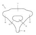
本発明の脊椎制動具について説明するに先立って、脊椎について簡単に説明する。脊椎は複数の椎骨が連なって構成されている。図1は、一つの椎骨10を概略的に示した平面図である。図1において、紙面上が腹側、下が背側、手前が頭部側、奥が臀部側である。椎骨10は、腹側にある楕円形に近い形の椎体11と該椎体11の背側に備えられる椎弓12とを有している。椎弓12の背側には棘突起14があり、左右には横突起13、13がある。また、椎体11と椎弓12との間には椎孔15が形成されており、椎孔15には脊髄腔が貫通する。頚椎、胸椎、腰椎において椎体11はほぼ同じような形をしているが、椎弓12はそれぞれ異なった複雑な形状をしている。本発明の脊椎制動具は、以下に説明するように、椎弓12に装着して用いることができる。なお、図面には頚椎を例示しているが、本発明の脊椎制動具は、頚椎、胸椎、及び腰椎のいずれの椎弓にも装着することができる。 Prior to describing the spine brake of the present invention, the spine will be briefly described. The spine is composed of a plurality of vertebrae. FIG. 1 is a plan view schematically showing one
<脊椎制動具50>
図2〜図4は一つの実施形態にかかる脊椎制動具50を概略的に示した図である。図2は、椎骨10、10に装着した姿勢の脊椎制動具50を概略的に示した平面図である。図2において、紙面上が腹側、下が背側、手前が頭部側、奥が臀部側である。図3は、椎骨10、10に装着した姿勢の脊椎制動具50を概略的に示した側面図である。図3において、紙面右が腹側、左が背側、上が頭部側、下が臀部側である。図4は、椎骨10、10に装着した姿勢の脊椎制動具50を概略的に示した背面図である。図4において、紙面奥が腹側、手前が背側、上が頭部側、下が臀部側である。<
2-4 is the figure which showed schematically the
脊椎制動具50は、複数の椎骨に装着して脊椎の動きを制御するものである。脊椎制動具50は、隣接する椎骨のうち頭部側の椎骨10aが有する椎弓12aの少なくとも一部を覆うことで該椎骨10aに固定可能な第1の被覆部20と、隣接する椎骨のうち臀部側の椎骨10bが有する椎弓12bの少なくとも一部を覆うことで該椎骨10bに固定可能な第2の被覆部30と、第1の被覆部20と第2の被覆部30との相対的位置を変更可能に第1の被覆部20と第2の被覆部30とを連結する関節部40とを備えている。以下、脊椎制動具50に備えられるこれら主要部について説明する。 The
(第1の被覆部20)
第1の被覆部20(以下、「被覆部20」と略記する。)は、椎弓12aの頭部側を覆う第1の頭部側部材21(以下、「頭部側部材21」と略記する。)と、椎弓12aの臀部側を覆う第1の臀部側部材22(以下、「臀部側部材22」と略記する。)とを備えている。被覆部20は、頭部側部材21と臀部側部材22とで椎弓12aを挟んで結合させることによって、椎弓12aの少なくとも一部を覆っている。さらに、後述するように被覆部20は椎弓12aの表面の凹凸形状に精密に一致する密着面を備えている。そのため、被覆部20によって椎弓12aの少なくとも一部を覆うことで、椎骨10aにスクリューなどを打ち込まなくとも、被覆部20を椎骨10aに固定することができる。(First covering portion 20)
The first covering part 20 (hereinafter abbreviated as “covering
頭部側部材21は椎弓12aに接する部分の左右両側に耳部21a、21aを有している。また、臀部側部材22も椎弓12aに接する部分の左右両側に耳部22a、22aを有している。頭部側部材21及び臀部側部材22は、耳部21a、21a及び耳部22a、22aにおいて固定具23、23によって連結され、結合される。固定具23は、頭部側部材21及び臀部側部材22を連結させることができるものであれば特に限定されない。固定具23としては、例えばボルトなどを用いることができる。 The head-
上述したように、被覆部20は椎弓12aの少なくとも一部を覆うことによって椎骨10aに固定することができる。被覆部20で椎弓12aを覆って被覆部20を椎骨10aに固定するため、被覆部20(頭部側部材21及び臀部側部材22の夫々)は椎弓12aの表面形状と雄雌の関係の形状を有して椎弓12aに密着可能な密着面を、椎弓12aに接する側の面に備えている。すなわち、被覆部20は、椎弓12aに接する側の面に、椎弓12aの表面の凹凸形状に精密に一致するように成形された密着面を備えている。複数の椎骨がそれぞれ有する椎弓は、それぞれ異なった表面形状を有している。よって、上記密着面は該密着面が接する椎弓の表面形状に応じて成形されており、被覆部毎に密着面の形状は異なっている。被覆部20がこのような密着面を備えている形態とすることによって、被覆部20を椎弓12aに密着させて被覆部20の装着位置がずれることを防止し、被覆部20を椎骨10aに固定することが容易になる。 As described above, the covering
被覆部20の作製方法は特に限定されない。ただし、上述したように、被覆部20の椎弓12aに接する側の面には上記密着面が備えられており、該密着面は、被覆部20を装着する椎弓12a(椎骨10a)の表面形状に合わせて作製する。密着面が椎弓12aの被覆部20に接する部分の表面と精密に雌雄の関係になるように被覆部20を作製するには、例えば、椎骨10aの断層撮影情報を三次元化した立体的表面画像データを用いて、粉末焼結積層造形法などの公知の技術によって被覆部20を構成する各部材を作製することができる。粉末焼結積層造形法に用いる装置としては、例えば、株式会社NTTデータエンジニアリングシステムズ製の「EOSINT M」等がある。また、断層撮影情報は、X線CT(X−ray Computer Tomograpy)、MRI(Magnetic Resonance Imaging)、超音波撮影などの公知の方法のいずれか1種又は2種以上を複合して用いることによって、透視計測又は外形計測することによって得ることができる。なお、被覆部20を構成する各部材の作製方法は粉末焼結積層造形法に限定されず、例えば切削加工によって作製することも可能である。ただし、被覆部20を短時間に低コストで作製するという観点からは、粉末焼結積層造形法が好ましい。 The manufacturing method of the coating |
被覆部20を切削加工によって作製する場合、以下に説明するように、様々な椎弓の立体的表面画像データを蓄積しておくことによって、立体的表面画像データの取得から切削加工までの工程を短縮することができる。すなわち、まず様々な椎弓の立体的表面画像データを蓄積し、それらのデータを対象の条件(人種、年齢、性別、身長、体重など)によって分類しておく。そして、それらのデータに基づいて患者の条件毎に椎弓の形状を想定し、想定された椎弓の表面形状と概ね雌雄の関係になるように成形された面を有する被覆部をあらかじめ複数作製しておく。そうすることによって、実際の患者の椎弓の立体的表面画像データをもとにして術前にその椎弓に好適な被覆部を選び出し、手術中に被覆部を少し削るだけで被覆部を椎弓に密着させることができる。このように立体的表面画像データの取得から切削加工までの工程を短縮できれば、本術式が緊急に行われるべき場合に対処することできる。 When the covering
被覆部20を構成する材料は、使用に耐える強度を有するとともに生体に悪影響を与えないように被覆部20を構成できるものであれば特に限定されない。このような材料としては、例えば、チタン、チタン合金(例えばTi6AlV4)、ステンレス鋼、コバルトクロム合金、タルタンなどを挙げることができる。生体適合性の観点からは、チタン及びチタン合金が好ましい。The material which comprises the coating |
また、被覆部20は、密着面を含む部分においてメッシュ状又はスポンジ状に成形された部分(不図示)を備えていることが好ましい。「メッシュ状」とは、被覆部20の椎弓12aに接する側の面(腹側の面)から反対側の面(背側の面)へと貫通した孔を複数有する構造を意味している。「スポンジ状」とは、被覆部20の内部に微細な空洞が複数形成された構造を意味し、これらの空洞が不規則に連続した構造を有していてもよい。このようなメッシュ状又はスポンジ状に成形された部分を備えている形態とすることによって、被覆部20の椎弓12aと接する部分に微細な凸凹が形成されることになり、被覆部20を椎弓12aに取り付けた際の固定性が良くなる。 Moreover, it is preferable that the coating |
また、被覆部20がメッシュ状又はスポンジ状に成形された部分を有する場合、被覆部20の密着面及びメッシュ状又はスポンジ状に成形された部分に骨誘導基質(不図示)を備えていることが好ましい。密着面の表面、及び、メッシュ状の構造を構成する貫通孔の表面若しくは内部、又はスポンジ状の構造を構成する空洞の表面若しくは内部に骨誘導基質を備えている形態とすれば、メッシュ状又はスポンジ状に成形された部分を介して被覆部20の表面に骨形成が起こり(すなわち、メッシュ状又はスポンジ状に成形された部分に自家骨が入り込み)、被覆部20と椎骨10aとを一体化させて被覆部20を椎骨10aに恒久的に固定することが容易になる。 Moreover, when the coating |
ここで、「骨誘導基質」とは、骨再生誘導作用を有する、骨補填材あるいは骨再生促進物質を意味する。「骨補填材」としては、日本ですでに医療機器として承認されている骨欠損部に使用される材料で自家骨とほぼ同じ成分で徐々に自家骨と融合し一体化するもの(例えば、ハイドロキシアパタイトなど)、あるいは自家骨に置換されるもの(例えば、ベータリン酸三カルシウム(bTCP)など)が知られている。また、「骨再生促進物質」としては、骨形成を促進する作用のある物質で骨形成蛋白(bone morphogenetic protein(BMP))などが知られている。 Here, the “bone induction substrate” means a bone filling material or a bone regeneration promoting substance having a bone regeneration inducing action. “Bone prosthesis” is a material used for bone defects that have already been approved as medical devices in Japan, and gradually fuses and integrates with autologous bone with almost the same components as autologous bone (for example, hydroxy Apatite etc.) or those that are replaced with autologous bone (for example, beta tricalcium phosphate (bTCP) etc.) are known. In addition, as a “bone regeneration promoting substance”, a substance having an action of promoting bone formation, such as bone morphogenetic protein (BMP), is known.
(第2の被覆部30)
第2の被覆部30(以下、「被覆部30」と略記する。)は、椎弓12bの頭部側を覆う第2の頭部側部材31(以下、「頭部側部材31」と略記する。)と、椎弓12bの臀部側を覆う第2の臀部側部材32(以下、「臀部側部材32」と略記する。)とを備えている。被覆部30は、頭部側部材31と臀部側部材32とで椎弓12bを挟んで結合させることによって、椎弓12bの少なくとも一部を覆っている。さらに、後述するように被覆部30は椎弓12bの表面の凹凸形状に精密に一致する密着面を備えている。そのため、被覆部30によって椎弓12bの少なくとも一部を覆うことで、椎骨10bにスクリューなどを打ち込まなくとも、被覆部30を椎骨10bに固定することができる。(Second covering portion 30)
The second covering portion 30 (hereinafter abbreviated as “covering
頭部側部材31は椎弓12bに接する部分の左右両側に耳部31a、31aを有している。また、臀部側部材32も椎弓12bに接する部分の左右両側に耳部32a、32aを有している。頭部側部材31及び臀部側部材32は、耳部31a、31a及び耳部32a、32aにおいて固定具33、33によって連結され、結合される。固定具33は、頭部側部材31及び臀部側部材32を連結させることができるものであれば特に限定されない。固定具33としては、例えばボルトなどを用いることができる。 The head-
上述したように、被覆部30は椎弓12bの少なくとも一部を覆うことによって椎骨10bに固定することができる。被覆部30で椎弓12bを覆って被覆部30を椎骨10bに固定するため、被覆部30(頭部側部材31及び臀部側部材32の夫々)は椎弓12bの表面形状と雄雌の関係の形状を有して椎弓12bに密着可能な密着面を、椎弓12bに接する側の面に備えている。すなわち、被覆部30は、椎弓12bに接する側の面に、椎弓12bの表面の凹凸形状に精密に一致するように成形された密着面を備えている。複数の椎骨がそれぞれ有する椎弓は、それぞれ異なった表面形状を有している。よって、上記密着面は該密着面が接する椎弓の表面形状に応じて成形されており、被覆部毎に密着面の形状は異なっている。被覆部30がこのような密着面を備えている形態とすることによって、被覆部30を椎弓12bに密着させて被覆部30の装着位置がずれることを防止し、被覆部30を椎骨10bに固定することが容易になる。As described above, the covering
被覆部30の作製方法は特に限定されない。ただし、上述したように、被覆部30の椎弓12bに接する側の面には上記密着面が備えられており、該密着面は、被覆部30を装着する椎弓12b(椎骨10b)の表面形状に合わせて作製する。密着面が椎弓12bの被覆部30に接する部分の表面と精密に雌雄の関係になるように被覆部30を作製するには、例えば、椎骨10bの断層撮影情報を三次元化した立体的表面画像データを用いて、粉末焼結積層造形法などの公知の技術によって被覆部30を構成する各部材を作製することができる。粉末焼結積層造形法に用いる装置としては、例えば、株式会社NTTデータエンジニアリングシステムズ製の「EOSINT M」等がある。また、断層撮影情報は、X線CT(X−ray Computer Tomograpy)、MRI(Magnetic Resonance Imaging)、超音波撮影などの公知の方法のいずれか1種又は2種以上を複合して用いることによって、透視計測又は外形計測することによって得ることができる。なお、被覆部30を構成する各部材の作製方法は粉末焼結積層造形法に限定されず、例えば切削加工によって作製することも可能である。ただし、被覆部30を短時間に低コストで作製するという観点からは、粉末焼結積層造形法が好ましい。 The manufacturing method of the coating |
被覆部30を切削加工によって作製する場合、様々な椎弓の立体的表面画像データを蓄積しておくことによって、上述した被覆部20と同様に、立体的表面画像データの取得から切削加工までの工程を短縮でき、手術が緊急に行われるべき場合に対処することできる。 When the covering
被覆部30を構成する材料は、使用に耐える強度を有するとともに生体に悪影響を与えないように被覆部30を構成できるものであれば特に限定されない。このような材料としては、例えば、チタン、チタン合金(例えばTi6AlV4)、ステンレス鋼、コバルトクロム合金、タルタンなどを挙げることができる。生体適合性の観点からは、チタン及びチタン合金が好ましい。The material which comprises the coating |
また、被覆部30は上述した被覆部20と同様に、密着面を含む部分においてメッシュ状又はスポンジ状に成形された部分(不図示)を備えていることが好ましい。さらに、被覆部30がメッシュ状又はスポンジ状に成形された部分を有する場合、上述した被覆部20と同様に、被覆部30の密着面及びメッシュ状又はスポンジ状に成形された部分に骨誘導基質(不図示)を備えていることが好ましい。 Moreover, it is preferable that the coating |
(関節部40)
関節部40は、被覆部20と被覆部30とを連結している。より具体的には、関節部40は、臀部側部材22と頭部側部材31とを連結している。すなわち、本実施形態では、臀部側部材22と頭部側部材31とが関節部40によって繋がれて一体となった一つの部材45(図3及び図4参照)を構成している。このように、頭部側部材21と、臀部側部材22、頭部側部材31、及び関節部40が一体になった部材45と、臀部側部材32とを備える形態とすることによって、被覆部20及び被覆部30を椎骨10a及び椎骨10bに着脱することが容易になるとともに、被覆部20及び被覆部30を関節部40で連結することが容易になる。(Joint 40)
The joint portion 40 connects the covering
関節部40は、被覆部20と被覆部30との相対的位置を適度に変更可能となる可動性を有して、被覆部20と被覆部30とを連結できるものであれば、特に限定されない。ここで「適度に変更可能となる可動性」とは、脊椎制動具50を用いる際に、患者の病状などに応じて適宜決定することができる程度の可動性を意味している。すなわち、病的意義のある不安定性を解消しつつ、かつ隣接椎間に過剰な力学的ストレスがかからない程度の可動性を有することを意味する。例えば、病状に応じて関節部40の可動域を調節あるいは固定することもできる。このような関節部40の可動性は、例えば、関節部40に含まれる関節の形状によって調節することができる。また、1個の関節部40は、1個あるいは複数の関節を組み合わせて構成することができ、1個の関節部40に含まれる関節の数によっても、関節部40の可動性を調節することができる。 The joint portion 40 is not particularly limited as long as the joint portion 40 has mobility that allows the relative position between the covering
関節部40を構成する材料としては、被覆部20及び被覆部30と同様の観点から、同様の材料を用いることができる。また、関節部40の関節は金属、セラミックあるいはポリエチレンに代表される人工素材で作製することもできる。 As a material constituting the joint portion 40, the same material can be used from the same viewpoint as the covering
<脊椎制動具50の使用方法>
脊椎制動具50は、被覆部20を椎弓12a(椎骨10a)に装着するとともに、被覆部30を椎弓12b(椎骨10b)に装着することによって、脊椎の動きを制御することができる。なお、使用に際して、脊椎制動具50には、ガス滅菌やコーティングなどによって滅菌処理を施すことが好ましい。<How to use the
The
上述したように、被覆部20は、頭部側部材21と臀部側部材22とに分けられている。椎弓12aを背面側から包み込むようにして頭部側部材21及び臀部側部材22を椎弓12aに被せ、頭部側部材21と臀部側部材22とを固定具23、23で連結することにより、頭部側部材21及び臀部側部材22が椎骨10aから外れなくなる。このようにして、被覆部20で椎弓12aの少なくとも一部を覆うことによって、被覆部20を椎骨10aに固定することができる。 As described above, the covering
被覆部30も被覆部20と同様に、頭部側部材31と臀部側部材32とに分けられている。椎弓12bを背面側から包み込むようにして頭部側部材31及び臀部側部材32を椎弓12bに被せ、頭部側部材31と臀部側部材32とを固定具33、33で連結することにより、頭部側部材31及び臀部側部材32が椎骨10bから外れなくなる。このようにして、被覆部30で椎弓12bの少なくとも一部を覆うことによって、被覆部30を椎骨10bに固定することができる。 The covering
臀部側部材22(被覆部20)と頭部側部材31(被覆部30)とは、関節部40によって繋がれているため、被覆部20が固定された椎骨10a、及び、被覆部30が固定された椎骨10bの相対的位置の変動は関節部40によって制御される。このようにして脊椎制動具50によって脊椎の動きを制御することができる。脊椎制動具50によれば、各椎骨同士の相対的位置の変動は関節部40によって制御されるので、脊椎を固定するのではなく、脊椎の過剰な不安定性を防いで制動することができる。 Since the buttocks side member 22 (covering part 20) and the head side member 31 (covering part 30) are connected by the joint part 40, the
また、脊椎制動具50によれば、上記のようにして脊椎の動きを制御しつつ、椎間板に人工のクッション(例えば、PVAハイドロゲル。)、培養椎間板(自己・同種・異種椎間板を培養したもの、幹細胞由来の椎間板など。)、及び椎間板再生を促進する物質(例えば、骨形成因子OP−1。)などを移植・充填・注射することができる。 Further, according to the
上述したように、従来技術ではスクリューなどを椎骨に刺入することによって種々の問題を生じる虞がある。一方、脊椎制動具50では、被覆部20及び被覆部30は椎弓12a及び椎弓12bを三次元的に密接に包み込む構造となっており、被覆部20及び被覆部30によって椎弓12a及び椎弓12bの少なくとも一部を覆うことで、被覆部20及び被覆部30が椎骨10a及び椎骨10bから外れなくすることができる。したがって、脊椎制動具50によれば、スクリューなどを椎骨に刺入することで生じ得る種々の問題の発生を防止できる。すなわち、脊椎制動具50は安全性が高く、新たな病変を生じさせる可能性も低い。ただし、本発明の脊椎制動具においても、被覆部を椎骨に固定するための脊椎固定スクリューなどの固定部材を補助的に使用することは可能である。固定部材を用いて被覆部を椎骨に固定することにより、より強固に被覆部を椎骨に固定することができる。このように脊椎固定スクリューを補助的に用いる場合、脊椎固定スクリューの数を従来よりも少なくすることができ、かつ、従来よりも刺し込む深さを浅くすることができるので、安全性が高く、新たな病変が生じることを防止できる。 As described above, in the prior art, various problems may be caused by inserting a screw or the like into the vertebra. On the other hand, in the
また、被覆部20及び被覆部30は椎骨10a及び椎骨10bに着脱可能であるため、粉末焼結積層造形法などの公知の技術によって脊椎(椎骨10a及び椎骨10b)の精密な模型を作製し、術前に該模型を用いて被覆部20及び被覆部30の装着などの手術シミュレーションを行ったり、術後の脊椎運動を予測する生物学的評価を行ったりすることも可能である。 Further, since the covering
<その他の形態>
上記脊椎制動具50の説明では、被覆部20、30を椎骨10a、10bに恒久的に固定することについて好ましい例として説明した。しかしながら、本発明の脊椎制動具の用途はそのような方法に限定されない。例えば、本発明の脊椎制動具は、一時的に脊椎を制動又は固定する目的で使用することもできる。図5は、一時的に脊椎を制動する目的で脊椎制動具50を使用する場合の使用例を概略的に示す図であり、図3に対応する図である。<Other forms>
In the description of the
一時的に脊椎を制動又は固定する目的で脊椎制動具50を使用する場合には、図5に示したように、腸骨などから採取した自家骨、自家椎間板、同種骨、同種椎間板、合成・培養椎間板組織など弾性のある組織60を移植して、脊椎制動具50が取り付けられる椎弓同士の相対的位置を固定する。そして、当該組織60が椎弓に癒合した後、脊椎制動具50を除去する。このように一時的に脊椎を制動する目的で脊椎制動具50を使用する場合には、後に脊椎制動具50を椎弓から外すことを前提としているので、脊椎制動具50の取り外しを容易にするため、被覆部20、30には上述したようなメッシュ状又はスポンジ状に成形された部分や、骨誘導基質は備えられていないことが好ましい。 When the
また、これまでの脊椎制動具50の説明では、隣接した椎骨に脊椎制動具50が装着される形態を例示して説明したが、本発明はかかる形態に限定されない。図6は、その他の実施形態にかかる脊椎制動具70を概略的に示した図であり、図3に対応する図である。 In the description of the
図6に示した脊椎制動具70は、被覆部20と被覆部30と被覆部20及び被覆部30を連結する関節部80とを備えている。本実施形態では、被覆部20が装着された椎骨10aと被覆部30が装着された椎骨10bとの間に他の椎骨10cが介在している。このように脊椎制動具70では、被覆部20と被覆部30とが離れた椎骨に取り付けられているため、関節部80は上述した関節部40に比べて長くなっているが、長さ以外の条件は関節部40と同様とすることができるので、詳細な説明は省略する。すなわち、関節部80も関節部40と同様に、関節部80に含まれる関節の形状や数によって、可動性を調節することができる。なお、脊椎制動具70のように離れた椎骨に装着する場合、脊椎制動具70の取り付けや関節部80の動きを妨げないようにするため、被覆部が取り付けられない椎骨10cについては椎弓などを切除しておくことが好ましい。 The
なお、図6では一つの椎骨を飛ばして装着する形態の脊椎制動具70を例示したが、本発明の脊椎制動具は二つ以上の椎骨を飛ばして離れた椎骨に装着する形態とすることも可能である。 6 illustrates the
また、これまでの本発明の説明では、被覆部が2つ備えられる形態を例示して説明したが、本発明の椎骨制動具はかかる形態に限定されない。本発明の椎骨制動具は、被覆部を3つ以上備えた形態とすることも可能である。すなわち、3つ以上の椎骨に装着することによって脊椎を制動することも可能である。図7は、他の実施形態にかかる脊椎制動具100を概略的に示した側面図である。図7は、椎骨10、10、…に装着した姿勢の脊椎制動具100の一部を概略的に示している。図7において、紙面右が腹側、左が背側、上が頭部側、下が臀部側である。 In the description of the present invention so far, the embodiment in which two covering portions are provided is described as an example. However, the vertebral brake device of the present invention is not limited to such a configuration. The vertebral brake device of the present invention can be configured to have three or more covering portions. That is, it is possible to brake the spine by attaching it to more than two vertebrae. FIG. 7 is a side view schematically showing a
脊椎制動具100は、複数の椎骨10、10、…に装着して脊椎の動きを制御可能である。脊椎制動具100は、複数の椎骨10、10、…の夫々について、該椎骨10、10、…が有する椎弓の少なくとも一部を覆うことで該椎骨10、10、…に固定可能な被覆部121〜125を備えている。また、被覆部121〜125のうち、隣り合う被覆部は相対的位置を変更可能なように関節部141〜143によって連結されている。被覆部121〜125は、夫々が椎骨10の頭部側を覆う頭部側部材131〜135と椎骨10の臀部側を覆う臀部側部材151〜155とを備えている。脊椎制動具100が取り付けられる椎骨10、10、…のうち最も頭部側の椎骨に固定可能な被覆部121を第1の被覆部とし、脊椎制動具100が取り付けられる椎骨10、10、…のうち頭部側からn番目(ただし、nは2以上の自然数)の椎骨に固定可能な被覆部を第nの被覆部としたとき、第n’の被覆部(ただし、n’は1からn−1までの自然数)に備えられる臀部側部材151〜155と、第n’+1の被覆部に備えられる頭部側部材132〜135と、第n’の被覆部に備えられる臀部側部材151〜155及び第n’+1の被覆部に備えられる頭部側部材132〜135を連結する関節部141〜143とが一体化されている。 The
脊椎制動具100において、関節部141〜143は関節部40又は関節部80と同様の形態とすることができるため、詳細な説明は省略する。また、被覆部121〜125は夫々配設される位置に応じて適切な形態に成形されるため、関節部141〜143が備えられる位置や椎弓に接する側の面の形状等は夫々異なるが、概ね被覆部20と同様の形態とすることができるため、詳細な説明は省略する。 In the
また、これまでの本発明の脊椎制動具の説明では、隣り合う一方の被覆部の一部と他方の被覆部の一部とが関節部を介して一体化されている形態を例示して説明したが、本発明の脊椎制動具はかかる形態に限定されない。本発明の椎制動具は、被覆部と関節部とが別々に成形されており、被覆部に対して関節部を着脱可能である形態であってもよい。かかる形態とすることによって、まず椎骨に被覆部を固定した後、隣り合う被覆部を関節部で連結することができる。例えば、独立して成形された複数の被覆部を夫々の椎骨に固定し、所定の期間が経過して自家骨により該被覆部が椎骨に恒久的に固定された後、隣り合う被覆部を関節部で連結することができる。 Further, in the description of the spine brake device of the present invention so far, a description is given by exemplifying a form in which a part of one adjacent covering part and a part of the other covering part are integrated via a joint part. However, the spine brake of the present invention is not limited to such a form. The vertebra brake device of the present invention may have a configuration in which the covering portion and the joint portion are separately formed, and the joint portion can be attached to and detached from the covering portion. By setting it as this form, after fixing a coating | coated part to a vertebra first, an adjacent coating | coated part can be connected by a joint part. For example, a plurality of independently formed covering portions are fixed to each vertebra, and after a predetermined period of time, the covering portions are permanently fixed to the vertebra by autologous bone, and then adjacent covering portions are jointed. It can be connected at the part.
また、これまでの本発明の脊椎制動具の説明では、被覆部が頭部側部材と臀部側部材とを備えている形態を例示して説明したが、本発明の脊椎制動具はかかる形態に限定されない。本発明の脊椎制動具において、被覆部は、椎骨に着脱可能であり、椎骨が有する椎弓の少なくとも一部を覆うようにして椎骨に取り付けたときに該椎骨との相対的位置を固定可能となる形態であれば、特に限定されない。例えば、これまでの本発明の説明では、被覆部を構成する2つの部材によって椎弓を上下方向に挟み込む形態について説明したが、本発明において、被覆部を構成する部材の数及びそれらの部材によって椎弓を挟み込む(包む)方向は特に限定されない。ただし、被覆部の椎骨への着脱のし易さ等の観点からは、被覆部が頭部側部材と臀部側部材とに分けて成形されている形態が好ましい。 Further, in the description of the spine brake device of the present invention so far, the embodiment in which the covering portion includes the head side member and the buttock side member has been described as an example, but the spine brake device of the present invention is in this form. It is not limited. In the spinal brake device of the present invention, the covering portion is detachable from the vertebra, and can be fixed in a relative position with respect to the vertebra when attached to the vertebra so as to cover at least a part of the vertebral vertebra having the vertebra. If it is the form which becomes, it will not specifically limit. For example, in the description of the present invention so far, the form in which the vertebral arch is sandwiched in the vertical direction by two members constituting the covering portion has been described, but in the present invention, the number of members constituting the covering portion and those members The direction of sandwiching (wrapping) the vertebral arch is not particularly limited. However, from the viewpoint of easy attachment / detachment of the covering portion to / from the vertebra, a form in which the covering portion is divided into a head side member and a buttocks side member is preferable.
また、これまでの本発明の脊椎制動具の説明では、頭部側部材と臀部側部材とが耳部において固定具によって連結される形態を例示して説明したが、本発明の脊椎制動具はかかる形態に限定されない。本発明の脊椎制動具において、被覆部を複数の部材で構成し、該複数の部材を結合させることによって被覆部で椎弓を覆う形態とする場合、該複数の部材を結合させる方法は特に限定されない。例えば、各部材を嵌合することによって結合できる形態であってもよい。 Further, in the description of the spine brake device of the present invention so far, the head side member and the buttocks side member have been described by exemplifying the form in which the ear portion is connected by the fixing device. It is not limited to such a form. In the spinal brake device of the present invention, when the covering portion is constituted by a plurality of members and the vertebral arch is covered with the covering portion by combining the plurality of members, the method of connecting the plurality of members is particularly limited. Not. For example, the form which can be couple | bonded by fitting each member may be sufficient.
10、10a、10b、10c 椎骨
11 椎体
12、12a、12b 椎弓
13 横突起
14 棘突起
15 椎孔
20 第1の被覆部
21 第1の頭部側部材
21a 耳部
22 第1の臀部側部材
22a 耳部
23 固定具
30 第2の被覆部
31 第2の頭部側部材
31a 耳部
32 第2の臀部側部材
32a 耳部
33 固定具
40、80 関節部
50、70、100 脊椎制動具
60 弾性のある組織10, 10 a, 10 b, 10
Claims (9)
Translated fromJapanese前記複数の椎骨の夫々について、該椎骨が有する椎弓の少なくとも一部を覆うことで該椎骨に固定可能な被覆部と、
隣り合う前記被覆部の相対的位置を変更可能に隣り合う前記被覆部を連結する関節部と、を備えており、
前記被覆部は夫々密着面を有する2つ以上の部材を備えており、
前記密着面は前記椎弓の表面形状と雄雌の関係の形状を有して前記椎弓に密着可能な面であり、
前記関節部が隣り合う前記被覆部の間に配置されている、脊椎制動具。A spine brake that can be attached to multiple vertebrae to control the movement of the spine,
For each of the plurality of vertebrae, a covering portion that can be fixed to the vertebrae by covering at least a part of the vertebral arch of the vertebrae,
A joint portion that connects the adjacent covering portions so that the relative position of the adjacent covering portions can be changed, and
The covering portion includes two or more members each having a close contact surface,
The contact surface is a surface that has a shape of a relationship between the surface shape of the vertebral arch and a male and female and can be in close contact with the vertebral arch,
The spine brake device, wherein the joint portion is disposed between the covering portions adjacent to each other.
前記隣り合う被覆部のうち臀部側の前記被覆部が、前記椎弓の頭部側を覆う第2の頭部側部材と、前記椎弓の臀部側を覆う第2の臀部側部材とを備え、
前記第1の臀部側部材と前記第2の頭部側部材と前記第1の臀部側部材及び前記第2の頭部側部材を連結する前記関節部とが一体化されている、請求項1又は2に記載の脊椎制動具Of the adjacent covering parts, the covering part on the head side includes a first head side member that covers the head side of the vertebral arch, and a first buttocks side member that covers the buttocks side of the vertebral arch. Prepared,
Of the adjacent covering parts, the covering part on the buttocks side includes a second head side member that covers the head side of the vertebral arch, and a second buttocks side member that covers the buttocks side of the vertebral arch. ,
The said 1st buttocks side member, the said 2nd head side member, and the said joint part which connects the said 1st buttocks side member and the said 2nd head side member are integrated. Or spine brake device of 2
前記被覆部が固定される椎骨のうち最も頭部側の椎骨に固定可能な被覆部を第1の被覆部とし、前記被覆部が固定される椎骨のうち頭部側からn番目(ただし、nは2以上の自然数)の椎骨に固定可能な被覆部を第nの被覆部としたとき、第n’の被覆部(ただし、n’は1からn−1までの自然数。)に備えられる前記臀部側部材と、第n’+1の被覆部に備えられる前記頭部側部材と、前記第n’の被覆部に備えられる前記臀部側部材及び第n’+1の被覆部に備えられる前記頭部側部材を連結する前記関節部とが一体化されている、請求項1〜3のいずれか一項に記載の脊椎制動具。Each of the covering portions includes a head side member that covers the head side of the vertebral arch and a buttock side member that covers the buttocks side of the vertebral arch,
Of the vertebrae to which the covering portion is fixed, the covering portion that can be fixed to the vertebra on the most head side is defined as a first covering portion, and the vertebra to which the covering portion is fixed is nth from the head side (however, n Is a natural number greater than or equal to 2), when the covering portion that can be fixed to the vertebra is the nth covering portion, the n′th covering portion (where n ′ is a natural number from 1 to n−1) is provided. The head side member, the head side member provided in the n ′ + 1 covering portion, the head side member provided in the n ′ covering portion, and the head portion provided in the n ′ + 1 covering portion. The spinal brake device according to any one of claims 1 to 3, wherein the joint portion connecting the side members is integrated.
Applications Claiming Priority (3)
| Application Number | Priority Date | Filing Date | Title |
|---|---|---|---|
| JP2011136665 | 2011-06-20 | ||
| JP2011136665 | 2011-06-20 | ||
| PCT/JP2012/065765WO2012176812A1 (en) | 2011-06-20 | 2012-06-20 | Spine immobilization tool |
Publications (2)
| Publication Number | Publication Date |
|---|---|
| JPWO2012176812A1 JPWO2012176812A1 (en) | 2015-02-23 |
| JP6044961B2true JP6044961B2 (en) | 2016-12-14 |
Family
ID=47422644
Family Applications (1)
| Application Number | Title | Priority Date | Filing Date |
|---|---|---|---|
| JP2013521603AActiveJP6044961B2 (en) | 2011-06-20 | 2012-06-20 | Spine brake |
Country Status (4)
| Country | Link |
|---|---|
| US (2) | US20140155939A1 (en) |
| EP (1) | EP2722013B1 (en) |
| JP (1) | JP6044961B2 (en) |
| WO (1) | WO2012176812A1 (en) |
Families Citing this family (13)
| Publication number | Priority date | Publication date | Assignee | Title |
|---|---|---|---|---|
| WO2006058221A2 (en) | 2004-11-24 | 2006-06-01 | Abdou Samy M | Devices and methods for inter-vertebral orthopedic device placement |
| US8568453B2 (en)* | 2007-01-29 | 2013-10-29 | Samy Abdou | Spinal stabilization systems and methods of use |
| US8764806B2 (en) | 2009-12-07 | 2014-07-01 | Samy Abdou | Devices and methods for minimally invasive spinal stabilization and instrumentation |
| US8845728B1 (en) | 2011-09-23 | 2014-09-30 | Samy Abdou | Spinal fixation devices and methods of use |
| US20130226240A1 (en) | 2012-02-22 | 2013-08-29 | Samy Abdou | Spinous process fixation devices and methods of use |
| US9198767B2 (en) | 2012-08-28 | 2015-12-01 | Samy Abdou | Devices and methods for spinal stabilization and instrumentation |
| US9320617B2 (en) | 2012-10-22 | 2016-04-26 | Cogent Spine, LLC | Devices and methods for spinal stabilization and instrumentation |
| US10857003B1 (en) | 2015-10-14 | 2020-12-08 | Samy Abdou | Devices and methods for vertebral stabilization |
| AU2016369593B2 (en) | 2015-12-16 | 2021-04-01 | Nuvasive, Inc. | Porous spinal fusion implant |
| US10973648B1 (en) | 2016-10-25 | 2021-04-13 | Samy Abdou | Devices and methods for vertebral bone realignment |
| US10744000B1 (en) | 2016-10-25 | 2020-08-18 | Samy Abdou | Devices and methods for vertebral bone realignment |
| US11179248B2 (en) | 2018-10-02 | 2021-11-23 | Samy Abdou | Devices and methods for spinal implantation |
| CN110585490B (en)* | 2019-09-16 | 2022-05-20 | 上理检测技术(上海)有限公司 | Micro-motion pressurizing steel plate |
Family Cites Families (29)
| Publication number | Priority date | Publication date | Assignee | Title |
|---|---|---|---|---|
| US4611582A (en)* | 1983-12-27 | 1986-09-16 | Wisconsin Alumni Research Foundation | Vertebral clamp |
| US5007909A (en)* | 1986-11-05 | 1991-04-16 | Chaim Rogozinski | Apparatus for internally fixing the spine |
| EP0934026B1 (en) | 1996-10-24 | 2009-07-15 | Zimmer Spine Austin, Inc | Apparatus for spinal fixation |
| US8133421B2 (en)* | 1999-02-23 | 2012-03-13 | Warsaw Orthopedic, Inc. | Methods of making shaped load-bearing osteoimplant |
| FR2794357B1 (en)* | 1999-06-01 | 2001-09-14 | Frederic Fortin | DISTRACTION DEVICE FOR BONES OF CHILDREN HAVING HANGING AND ADJUSTMENT MEANS FOR TRACKING GROWTH |
| FR2811540B1 (en)* | 2000-07-12 | 2003-04-25 | Spine Next Sa | IMPORTING INTERVERTEBRAL IMPLANT |
| JP2003038507A (en) | 2001-08-01 | 2003-02-12 | Showa Ika Kohgyo Co Ltd | Implant for bone joining implement |
| JP3927487B2 (en) | 2002-12-02 | 2007-06-06 | 株式会社大野興業 | Manufacturing method of artificial bone model |
| US7658753B2 (en)* | 2004-08-03 | 2010-02-09 | K Spine, Inc. | Device and method for correcting a spinal deformity |
| FR2884136B1 (en)* | 2005-04-08 | 2008-02-22 | Spinevision Sa | INTERVERTEBRAL SURGICAL IMPLANT FORMING BALL |
| ES2556111T3 (en)* | 2005-04-08 | 2016-01-13 | Paradigm Spine, Llc | Interspinous vertebral and lumbosacral stabilization devices |
| US20060271055A1 (en)* | 2005-05-12 | 2006-11-30 | Jeffery Thramann | Spinal stabilization |
| US7837688B2 (en)* | 2005-06-13 | 2010-11-23 | Globus Medical | Spinous process spacer |
| EP1942817B1 (en)* | 2005-09-27 | 2014-05-07 | Paradigm Spine, LLC | Interspinous vertebral stabilization devices |
| US7806911B2 (en) | 2006-04-14 | 2010-10-05 | Warsaw Orthopedic, Inc. | Fixation plate and method of use |
| US8048118B2 (en)* | 2006-04-28 | 2011-11-01 | Warsaw Orthopedic, Inc. | Adjustable interspinous process brace |
| US8246680B2 (en)* | 2006-05-25 | 2012-08-21 | Spinemedica, Llc | Patient-specific spinal implants and related systems and methods |
| FR2905848B1 (en)* | 2006-09-18 | 2008-12-05 | Spineart Sa | LUMBAR INTER-SPINOUS PROSTHESIS AND ITS APPLICATIONS |
| KR100829338B1 (en)* | 2006-12-07 | 2008-05-13 | 김수경 | Spinal fixture |
| US8435268B2 (en)* | 2007-01-19 | 2013-05-07 | Reduction Technologies, Inc. | Systems, devices and methods for the correction of spinal deformities |
| FR2915367B1 (en)* | 2007-04-24 | 2010-09-17 | David Attia | ENHANCED INTERVERTEBRAL IMPULSE IMPLANT TO ENHANCE CERTAIN INTERBREAK MOVEMENTS |
| US20080294200A1 (en)* | 2007-05-25 | 2008-11-27 | Andrew Kohm | Spinous process implants and methods of using the same |
| US8790380B2 (en)* | 2007-07-26 | 2014-07-29 | Dynamic Spine, Llc | Segmental orthopaedic device for spinal elongation and for treatment of scoliosis |
| US9204908B2 (en)* | 2007-07-26 | 2015-12-08 | Dynamic Spine, Llc | Segmental orthopedic device for spinal elongation and for treatment of scoliosis |
| CA2697170A1 (en)* | 2007-09-14 | 2009-03-19 | Synthes Usa, Llc | Interspinous spacer |
| US8623062B2 (en)* | 2008-09-29 | 2014-01-07 | Dimitriy G. Kondrashov | System and method to stablize a spinal column including a spinolaminar locking plate |
| EP2440145A4 (en)* | 2009-06-08 | 2013-12-11 | Reduction Technologies Inc | Systems, methods and devices for correcting spinal deformities |
| WO2013064997A1 (en)* | 2011-10-31 | 2013-05-10 | NLT-Spine Ltd. | Bony structure fixation clamp |
| US20130218208A1 (en)* | 2012-02-16 | 2013-08-22 | The Uab Research Foundation | Rod-receiving spinal fusion attachment elements |
- 2012
- 2012-06-20JPJP2013521603Apatent/JP6044961B2/enactiveActive
- 2012-06-20USUS14/128,225patent/US20140155939A1/ennot_activeAbandoned
- 2012-06-20EPEP12803130.9Apatent/EP2722013B1/enactiveActive
- 2012-06-20WOPCT/JP2012/065765patent/WO2012176812A1/enactiveApplication Filing
- 2016
- 2016-04-14USUS15/098,820patent/US10149705B2/enactiveActive
Also Published As
| Publication number | Publication date |
|---|---|
| US20140155939A1 (en) | 2014-06-05 |
| EP2722013A4 (en) | 2015-08-19 |
| JPWO2012176812A1 (en) | 2015-02-23 |
| WO2012176812A1 (en) | 2012-12-27 |
| US20160228158A1 (en) | 2016-08-11 |
| US10149705B2 (en) | 2018-12-11 |
| EP2722013B1 (en) | 2016-10-26 |
| EP2722013A1 (en) | 2014-04-23 |
Similar Documents
| Publication | Publication Date | Title |
|---|---|---|
| JP6044961B2 (en) | Spine brake | |
| JP7527964B2 (en) | Systems and methods for multiplanar orthopedic alignment - Patents.com | |
| US11376049B2 (en) | Fixation devices having fenestrations and methods for using the same | |
| Mobbs et al. | Anterior lumbar interbody fusion using a personalized approach: is custom the future of implants for anterior lumbar interbody fusion surgery? | |
| EP2772230A1 (en) | Fusion prosthesis | |
| US20190314169A1 (en) | Coated and layered vertebral disc arthrodesis prothesis | |
| CN209770594U (en) | Self-stabilizing type multi-hole interbody fusion cage | |
| Chung et al. | Vertebral reconstruction with customized 3-dimensional− printed spine implant replacing large vertebral defect with 3-year follow-up | |
| CN107569309B (en) | Vertebral prosthesis capable of being implanted into long bone | |
| US20220031460A1 (en) | Patient specific graft cage for craniomaxillofacial repair | |
| JP2021505251A (en) | How to make a custom-made graft | |
| CN102429747A (en) | Atlas fusion prosthesis | |
| WO2017209605A1 (en) | Implant, fitting plate and method of manufacturing an implant and fitting plate | |
| US20250127624A1 (en) | Implantable medical device | |
| KR102196502B1 (en) | Cervical Stand-Alone Cage with Porous Structure | |
| CN107569308B (en) | Porous integrated cervical vertebra fusion device | |
| Sãlcianu et al. | 3D TECHNOLOGIES IN THE DEVELOPMENT OF BIOMATERIALS FOR ORTHOPEDICS: EFFICIENCY AND PRECISION IN MODERN SURGERY | |
| CN107174325A (en) | Backbone fixation kit | |
| JP6664114B2 (en) | Spinal brake | |
| CN113244026A (en) | Assembled sacrum reconstruction prosthesis | |
| Yahya et al. | Biomechanical Analysis of Spinal Fusion Cage for Lumbar Vertebrae | |
| US20240277487A1 (en) | Interbody device incorporating lattice structure and related systems and methods | |
| Kępa et al. | The modelling and strength analysis of the endoprosthesis of the knee joint | |
| BG67358B1 (en) | Method of designing patient-specific implants for surgical treatment of diseases in the cervical spine | |
| CN119868019A (en) | Fusion device for lumbar articular process joint |
Legal Events
| Date | Code | Title | Description |
|---|---|---|---|
| A621 | Written request for application examination | Free format text:JAPANESE INTERMEDIATE CODE: A621 Effective date:20150619 | |
| A131 | Notification of reasons for refusal | Free format text:JAPANESE INTERMEDIATE CODE: A131 Effective date:20160517 | |
| A521 | Request for written amendment filed | Free format text:JAPANESE INTERMEDIATE CODE: A523 Effective date:20160609 | |
| TRDD | Decision of grant or rejection written | ||
| A01 | Written decision to grant a patent or to grant a registration (utility model) | Free format text:JAPANESE INTERMEDIATE CODE: A01 Effective date:20161025 | |
| A61 | First payment of annual fees (during grant procedure) | Free format text:JAPANESE INTERMEDIATE CODE: A61 Effective date:20161108 | |
| R150 | Certificate of patent or registration of utility model | Ref document number:6044961 Country of ref document:JP Free format text:JAPANESE INTERMEDIATE CODE: R150 | |
| R250 | Receipt of annual fees | Free format text:JAPANESE INTERMEDIATE CODE: R250 | |
| R250 | Receipt of annual fees | Free format text:JAPANESE INTERMEDIATE CODE: R250 | |
| S111 | Request for change of ownership or part of ownership | Free format text:JAPANESE INTERMEDIATE CODE: R313113 | |
| R350 | Written notification of registration of transfer | Free format text:JAPANESE INTERMEDIATE CODE: R350 | |
| R250 | Receipt of annual fees | Free format text:JAPANESE INTERMEDIATE CODE: R250 | |
| R250 | Receipt of annual fees | Free format text:JAPANESE INTERMEDIATE CODE: R250 | |
| R250 | Receipt of annual fees | Free format text:JAPANESE INTERMEDIATE CODE: R250 | |
| R250 | Receipt of annual fees | Free format text:JAPANESE INTERMEDIATE CODE: R250 |