JP6044608B2 - Lighting device and communication system - Google Patents
Lighting device and communication systemDownload PDFInfo
- Publication number
- JP6044608B2 JP6044608B2JP2014178969AJP2014178969AJP6044608B2JP 6044608 B2JP6044608 B2JP 6044608B2JP 2014178969 AJP2014178969 AJP 2014178969AJP 2014178969 AJP2014178969 AJP 2014178969AJP 6044608 B2JP6044608 B2JP 6044608B2
- Authority
- JP
- Japan
- Prior art keywords
- terminal
- unit
- wireless
- lighting
- wireless communication
- Prior art date
- Legal status (The legal status is an assumption and is not a legal conclusion. Google has not performed a legal analysis and makes no representation as to the accuracy of the status listed.)
- Active
Links
Images


Classifications
- F—MECHANICAL ENGINEERING; LIGHTING; HEATING; WEAPONS; BLASTING
- F21—LIGHTING
- F21K—NON-ELECTRIC LIGHT SOURCES USING LUMINESCENCE; LIGHT SOURCES USING ELECTROCHEMILUMINESCENCE; LIGHT SOURCES USING CHARGES OF COMBUSTIBLE MATERIAL; LIGHT SOURCES USING SEMICONDUCTOR DEVICES AS LIGHT-GENERATING ELEMENTS; LIGHT SOURCES NOT OTHERWISE PROVIDED FOR
- F21K9/00—Light sources using semiconductor devices as light-generating elements, e.g. using light-emitting diodes [LED] or lasers
- F21K9/20—Light sources comprising attachment means
- F21K9/27—Retrofit light sources for lighting devices with two fittings for each light source, e.g. for substitution of fluorescent tubes
- H—ELECTRICITY
- H05—ELECTRIC TECHNIQUES NOT OTHERWISE PROVIDED FOR
- H05B—ELECTRIC HEATING; ELECTRIC LIGHT SOURCES NOT OTHERWISE PROVIDED FOR; CIRCUIT ARRANGEMENTS FOR ELECTRIC LIGHT SOURCES, IN GENERAL
- H05B47/00—Circuit arrangements for operating light sources in general, i.e. where the type of light source is not relevant
- H05B47/10—Controlling the light source
- H05B47/175—Controlling the light source by remote control
- H05B47/19—Controlling the light source by remote control via wireless transmission
- H—ELECTRICITY
- H05—ELECTRIC TECHNIQUES NOT OTHERWISE PROVIDED FOR
- H05B—ELECTRIC HEATING; ELECTRIC LIGHT SOURCES NOT OTHERWISE PROVIDED FOR; CIRCUIT ARRANGEMENTS FOR ELECTRIC LIGHT SOURCES, IN GENERAL
- H05B47/00—Circuit arrangements for operating light sources in general, i.e. where the type of light source is not relevant
- H05B47/10—Controlling the light source
- H05B47/175—Controlling the light source by remote control
- H05B47/198—Grouping of control procedures or address assignation to light sources
- H05B47/199—Commissioning of light sources
- F—MECHANICAL ENGINEERING; LIGHTING; HEATING; WEAPONS; BLASTING
- F21—LIGHTING
- F21S—NON-PORTABLE LIGHTING DEVICES; SYSTEMS THEREOF; VEHICLE LIGHTING DEVICES SPECIALLY ADAPTED FOR VEHICLE EXTERIORS
- F21S8/00—Lighting devices intended for fixed installation
- F21S8/03—Lighting devices intended for fixed installation of surface-mounted type
- F21S8/031—Lighting devices intended for fixed installation of surface-mounted type the device consisting essentially only of a light source holder with an exposed light source, e.g. a fluorescent tube
- F—MECHANICAL ENGINEERING; LIGHTING; HEATING; WEAPONS; BLASTING
- F21—LIGHTING
- F21S—NON-PORTABLE LIGHTING DEVICES; SYSTEMS THEREOF; VEHICLE LIGHTING DEVICES SPECIALLY ADAPTED FOR VEHICLE EXTERIORS
- F21S9/00—Lighting devices with a built-in power supply; Systems employing lighting devices with a built-in power supply
- F21S9/02—Lighting devices with a built-in power supply; Systems employing lighting devices with a built-in power supply the power supply being a battery or accumulator
- F21S9/022—Emergency lighting devices
- F—MECHANICAL ENGINEERING; LIGHTING; HEATING; WEAPONS; BLASTING
- F21—LIGHTING
- F21V—FUNCTIONAL FEATURES OR DETAILS OF LIGHTING DEVICES OR SYSTEMS THEREOF; STRUCTURAL COMBINATIONS OF LIGHTING DEVICES WITH OTHER ARTICLES, NOT OTHERWISE PROVIDED FOR
- F21V23/00—Arrangement of electric circuit elements in or on lighting devices
- F21V23/04—Arrangement of electric circuit elements in or on lighting devices the elements being switches
- F21V23/0442—Arrangement of electric circuit elements in or on lighting devices the elements being switches activated by means of a sensor, e.g. motion or photodetectors
- F21V23/045—Arrangement of electric circuit elements in or on lighting devices the elements being switches activated by means of a sensor, e.g. motion or photodetectors the sensor receiving a signal from a remote controller
- F—MECHANICAL ENGINEERING; LIGHTING; HEATING; WEAPONS; BLASTING
- F21—LIGHTING
- F21V—FUNCTIONAL FEATURES OR DETAILS OF LIGHTING DEVICES OR SYSTEMS THEREOF; STRUCTURAL COMBINATIONS OF LIGHTING DEVICES WITH OTHER ARTICLES, NOT OTHERWISE PROVIDED FOR
- F21V29/00—Protecting lighting devices from thermal damage; Cooling or heating arrangements specially adapted for lighting devices or systems
- F21V29/85—Protecting lighting devices from thermal damage; Cooling or heating arrangements specially adapted for lighting devices or systems characterised by the material
- F—MECHANICAL ENGINEERING; LIGHTING; HEATING; WEAPONS; BLASTING
- F21—LIGHTING
- F21Y—INDEXING SCHEME ASSOCIATED WITH SUBCLASSES F21K, F21L, F21S and F21V, RELATING TO THE FORM OR THE KIND OF THE LIGHT SOURCES OR OF THE COLOUR OF THE LIGHT EMITTED
- F21Y2115/00—Light-generating elements of semiconductor light sources
- F21Y2115/10—Light-emitting diodes [LED]
Landscapes
- Engineering & Computer Science (AREA)
- General Engineering & Computer Science (AREA)
- Physics & Mathematics (AREA)
- Microelectronics & Electronic Packaging (AREA)
- Optics & Photonics (AREA)
- Computer Networks & Wireless Communication (AREA)
- Arrangement Of Elements, Cooling, Sealing, Or The Like Of Lighting Devices (AREA)
- Non-Portable Lighting Devices Or Systems Thereof (AREA)
- Position Fixing By Use Of Radio Waves (AREA)
- Circuit Arrangement For Electric Light Sources In General (AREA)
Description
Translated fromJapanese本発明は、照明装置及び通信システムに関する。 The present invention relates to a lighting device and a communication system.
GPSを用いた正確な測位が困難な施設において、人や物品の位置を把握し、管理するための様々な位置情報管理システムが提案されている。例えば、無線によって読み取りが可能なRFID(Radio-frequency IDentification)タグを人や物品に付して、その位置を把握するシステムが提案されている。 In a facility where accurate positioning using GPS is difficult, various position information management systems for grasping and managing the positions of people and articles have been proposed. For example, a system has been proposed in which an RFID (Radio-frequency IDentification) tag that can be read wirelessly is attached to a person or an article and the position thereof is grasped.
特許文献1には、無線端末が照明装置から発信される固有情報を受信し、該固有情報をサーバに送信することで、無線端末の位置を特定するシステムが開示されている。
しかしながら、従来のシステムは、照明装置に電源が供給されている間は測位システムとして機能するが、照明装置の電源が切られた場合には、照明装置から固有情報が発信されず、測位機能が停止してしまうという問題がある。 However, the conventional system functions as a positioning system while power is supplied to the lighting device. However, when the lighting device is turned off, unique information is not transmitted from the lighting device, and the positioning function is not provided. There is a problem of stopping.
本発明は上記に鑑みてなされたものであって、電源が遮断されても位置情報を管理するシステムに用いられる通信機能を維持可能な照明装置を提供することを目的とする。 The present invention has been made in view of the above, and an object of the present invention is to provide an illuminating device that can maintain a communication function used in a system that manages position information even when the power is turned off.
本発明の一態様によれば、無線端末に割り当てられた端末IDを受信する受信部と、受信した前記端末ID及び装置IDを送信する送信部と、光源からの光を外部に照射する照明部と、前記受信部及び前記送信部に電力を供給する二次電池と、前記照明部に着脱可能に設けられ、前記二次電池を収容する収容部と、を有する。According to one aspect of the present invention, a receiving unit that receives a terminal ID assigned to a wireless terminal, a transmitting unit that transmits the received terminal ID and device ID, and an illuminating unit that emits light from a light source to the outside Whenthe rechargeable battery for supplying electric power to the receiving unit and the transmittingunit, detachably attached to the lighting unit, havinga storage portion for storingthe secondary battery.
本発明の実施形態によれば、電源が遮断されても位置情報を管理するシステムに用いられる通信機能を維持可能な照明装置を提供できる。 According to the embodiment of the present invention, it is possible to provide a lighting device that can maintain a communication function used in a system that manages position information even when the power is turned off.
以下、図面を参照して発明を実施するための形態について説明する。各図面において、同一構成部分には同一符号を付し、重複した説明を省略する場合がある。 Hereinafter, embodiments for carrying out the invention will be described with reference to the drawings. In the drawings, the same components are denoted by the same reference numerals, and redundant description may be omitted.
以下、本発明の実施形態を図面に基づいて説明する。 Hereinafter, embodiments of the present invention will be described with reference to the drawings.
1.概要
2.ハードウェア構成例
3.機能
4.動作例
<1.概要>
図1は、本発明の概要を説明する図である。図1は、本発明の通信システムを含む、位置管理システム1の概略を示している。1.
FIG. 1 is a diagram for explaining the outline of the present invention. FIG. 1 shows an outline of a
位置管理システム1は、人又は物品に内蔵又は取り付けられた無線端末120a−120g(以下、無線端末120と表す)と、照明器具100と、ゲートウェイ140と、管理装置110とを含む。位置管理システム1は、空間内に設けられている照明器具100を介し、無線端末120に付された端末IDを随時取得して、人や物品の位置を監視する。 The
ここで、照明器具100は、予め位置と関連付けられた装置IDと、無線端末120から取得した端末IDとを組み合わせて、管理装置110に送信する。管理装置110は、装置IDがどの位置と対応するかを把握しているため、端末IDと位置とを対応付けることにより、無線端末の位置を特定できる。 Here, the
無線端末120aは、人が所持する社員証やIDカードに内蔵されるか、あるいは、外部に取り付けられてもよい。無線端末120b〜120gは、それぞれ、PC、プロジェクタ、会議用端末、机、複合機、清掃用具等に内蔵されるか、あるいは、外部に取り付けられてもよい。無線端末120は、割り当てられた端末IDを含むビーコン信号を、微弱無線、特定小電力無線、又は小電力無線等の、任意の無線通信を用いて送信できる。 The
<無線端末の概要>
図2は、無線端末120の外観図である。図2に例示される無線端末120は、人又は物品に付されるタグ状の無線端末である。図2に例示される無線端末120は、縦27mm×横45mm×奥行き7mm、重さ約8グラムの小型のタグであり、315MHz帯の微弱無線により、照明器具100と通信できる。<Overview of wireless terminal>
FIG. 2 is an external view of the
照明器具100は、他の照明器具及びゲートウェイ140と、無線ネットワークを形成し、無線端末120から受信した端末IDを、他の照明器具及びゲートウェイ140を介して、管理装置110に送信する。 The
図3は、照明器具100が、位置管理の対象となるコンテナのような物品に付された無線端末120から、端末IDを受信する例を示している。照明器具100は、自らの装置IDと受け取った端末IDとを、ゲートウェイ140(及び必要に応じて他の照明器具102)を介して、管理装置110に送信する。無線ネットワークは、例えば、IEEE802.15.4及びZigBee(登録商標)や、Bluetooth(登録商標)や、無線LAN等の近距離無線通信を用いて形成されてもよい。 FIG. 3 shows an example in which the
なお、図4は、図2に例示された無線端末120と、無線ネットワークを形成する複数の照明器具100,102,104,106及びゲートウェイ140とを、抜き出して記載した図である。 FIG. 4 is a diagram in which the
ゲートウェイ140は、照明器具100等と形成する無線ネットワークと、管理装置110と接続する有線ネットワークとを接続する装置である。ゲートウェイ140は、無線ネットワークにZigBeeが用いられるとき、無線ネットワークを構成して管理するZigBeeコーディネータとしての機能を有する。 The
管理装置110は、ゲートウェイ140を介して、照明器具100から送信されるIDを受信する装置である。管理装置110は、照明器具100に付された装置IDと、照明器具100の設置された位置とを関連付けて格納する。 The
<照明器具の概要>
次に、照明器具100の構成及び設置例について、図面に基づいて説明する。<Outline of lighting equipment>
Next, the structure and installation example of the
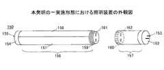
図5は、本発明の一実施形態における照明器具100の外観構成を示す図である。照明器具100は、光を発する直管型のランプである照明装置150と、照明装置150が取り付けられる照明器具本体130とを有する。 FIG. 5 is a diagram showing an external configuration of the
本発明の一実施形態における照明器具100が送信する装置IDは、照明装置150に設けられている記憶手段に格納されている。照明装置150は、無線端末120からビーコン信号を受信して端末IDを取得し、端末IDと共に装置IDを管理装置110に送信する。以下、照明器具本体130と照明装置150の構成を詳細に説明する。 The device ID transmitted by the
<照明器具本体>
照明器具本体130は、例えば、屋内の天井に設けられる。照明器具本体130は、天井に取り付けられる本体135と、照明装置150の端部が装着される第1ソケット131及び第2ソケット133とを有する。第1ソケット131は、照明装置150に給電する給電端子132を有する。また、第2ソケット133は、照明装置150に給電する給電端子134を有する。照明器具本体130は、第1ソケット131及び第2ソケット133に両端部が装着される照明装置150に、内部に設けられている電源供給部から給電端子132、134を介して電源を供給する。あるいは、照明器具本体130は、給電端子132及び給電端子134の何れか一方のみを用いて、照明装置150に電源を供給する片側給電であってもよい。<Lighting fixture body>
The luminaire
<照明装置>
照明装置150は、照明部156と、収容部157と、両端部に設けられている口金152,154と、接続端子153,155とを有する。照明部156と収容部157とは、図6に示すように、着脱可能に設けられている。なお、照明装置150全体の大きさ及び形状、口金152,154の形状等は、照明装置150が設置される国等の照明の規格に則って設けられてもよく、以下で説明する形状等に限られるものではない。<Lighting device>
The
照明部156は、構造体158と、透光性カバー151と、収容部157側の端部に設けられている雄ねじ構造159と、雄ねじ構造159の先端面に設けられている接続端子161とを有し、図6には不図示の光源を内部に収容している。構造体158は、例えば熱伝導率の高いマグネシウム合金等で形成される。透光性カバー151は、例えばアクリル樹脂等の樹脂材料で形成され、光源からの光を透過する。 The
収容部157は、照明部156側の端部に設けられている雌ねじ構造160と、雌ねじ構造160の内側端面に設けられている接続端子162とを有し、図6には不図示の二次電池を内部に収容している。なお、照明装置150としては、明るさ向上のために可能な範囲で照明部156を大きく、且つ、収容部157を小さく構成することが好ましく、取り扱い性向上のために出来るだけ軽量化されていることが好ましい。 The
照明部156の雄ねじ構造159及び収容部157の雌ねじ構造160は、螺合したときに照明部156の接続端子161と収容部157の接続端子162とが、所定の端子同士で接続する様に構成されている。 The
照明装置150は、照明部156と収容部157とが連結された状態で、口金152,154がそれぞれ第1ソケット131又は第2ソケット133に装着されることで、照明器具本体130に取り付けられる。 The illuminating
接続端子153,155は、照明装置150が照明器具本体130に取り付けられた時に、照明器具本体130の給電端子132,134に接続して電力の供給を受ける。あるいは、接続端子153,155の何れか一方のみが、給電端子132,134の何れか一方から電力の供給を受けてもよい。照明部156の内部に設けられている光源は、接続端子153,155から供給される電力により発光し、透光性カバー151を介して外部に光を照射する。また、収容部157に設けられている二次電池は、接続端子153,155から供給される電力を蓄える。 The
<照明装置の構成>
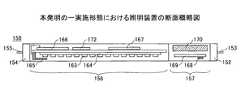
図7は、本発明の一実施形態における照明装置150の構成例を示す断面概略図である。図7に示す様に、照明装置150の照明部156は、内部に複数のLED素子163が配列された基板164と、第一の無線通信器165と、第一の無線通信モジュール166と、電源モジュール167と、CPUモジュール172とを有する。また、収容部157は、第二の無線通信器168と、第二の無線通信モジュール169と、二次電池170とを有する。<Configuration of lighting device>
FIG. 7 is a schematic cross-sectional view illustrating a configuration example of the
第一の無線通信モジュール166は、例えば第一の無線通信器165と無線端末120との間の通信を制御する無線通信制御部として機能する回路を有する基板である。例えば、第一の無線通信モジュール166は、微弱無線のビーコン受信機である。 The first
第二の無線通信モジュール169は、例えば第二の無線通信器168と管理装置110との間の通信を制御する無線通信制御部として機能する回路を有する基板である。例えば、第二の無線通信モジュール169は、近距離無線通信のルータ又はエンドデバイスである。 The second
CPUモジュール172は、第一の無線通信モジュール166及び第二の無線通信モジュール169に命令を与え、データの流れを制御する機能を有する基板である。 The
電源モジュール167は、接続端子153,155から供給される電力を整流、平滑化する電源制御部及びその電圧を変換する電圧変換部として機能する回路を有する基板である。 The
二次電池170は、例えばリチウムイオン二次電池であり、接続端子153,155から供給される電力を蓄える。なお、二次電池170は、リチウムイオン二次電池に限るものではなく、充電可能であれば他の二次電池であってもよい。二次電池170は、照明器具100に電力が供給されている間は、照明装置150に供給される電力を蓄える。また、二次電池170は、照明器具100の電源が遮断されたときには、第一の無線通信モジュール166、第二の無線通信モジュール169に電力を供給し、これらを動作させる予備電源として機能する。 The
この様に、照明装置150は、二次電池170を有することで、照明器具100の電源が遮断された場合であっても、第一の無線通信モジュール166及び第二の無線通信モジュール169に二次電池170から電力が供給される。したがって、照明器具100の電源が遮断された場合であっても、位置管理システム1に必要とされる機能は維持される。 As described above, the
また、二次電池170は、LED素子163を有する照明部156とは異なる収容部157に収容され、熱を生じるLED素子163とは隔絶された空間に設けられている。したがって、二次電池170が、複数のLED素子163が配列された基板164等からの熱の影響を受けて劣化する可能性が低減されている。 The
さらに、照明装置150は、収容部157が交換されてもよい。二次電池170が繰り返し充放電することで劣化した場合には、継続して使用可能なLED素子163を含む照明部156を残し、収容部157のみを交換することで、照明装置150として使用し続けることが可能になっている。 Further, in the
この様に、本実施形態における照明装置150では、二次電池170がLED素子163を含む照明部156に着脱可能な収容部157に設けられることで、熱による二次電池170の劣化が低減される。また、二次電池170が劣化した場合には収容部157のみを交換できるため、LED素子163等を含む照明部156は継続して使用することが可能であり、ランニングコスト及び環境への負荷が低減されている。 As described above, in the
なお、第一の無線通信器165及び第一の無線通信モジュール166を収容部157に設け、第二の無線通信器168及び第二の無線通信モジュール169を照明部156に設けてもよい。 Note that the first
また、図8に示すように、収容部157には、第二の無線通信器168、第二の無線通信モジュール169及び二次電池170に加えて、第一の無線通信器165、第一の無線通信モジュール166、電圧変換モジュール171、CPUモジュール172が設けられてもよい。第一の無線通信器165及び第二の無線通信器168は、照明部156に設けられるとLED素子163から照射される光を遮る可能性があるが、収容部157に設けられることで、LED素子163の光を遮ることが無い。 In addition to the second
さらに、図9に示すように、収容部157に、LED素子163からの光を反射する光反射部材174を設けてもよい。この場合には、照明部156及び収容部157のそれぞれの連結部分は、透光性の材料により形成される。照明装置150は、光反射部材174がLED素子163からの光を反射することで、より広範囲に光を照射することが可能になる。 Furthermore, as illustrated in FIG. 9, a
<照明器具の設置例>
図10は、オフィスに複数の照明器具が設置されている様子を例示する図であり、オフィス内の天井に設けられている照明器具が長方形で表されている。図10に示されている全156灯の照明器具のうち、本発明の一実施形態における照明器具100,102,104は網掛けの長方形で示され、通常の照明器具は白抜きの長方形で示されている。<Example of installation of lighting equipment>
FIG. 10 is a diagram illustrating a state in which a plurality of lighting fixtures are installed in the office, and the lighting fixtures provided on the ceiling in the office are represented by rectangles. Of the 156 lighting fixtures shown in FIG. 10, the
照明器具100,102,104は、それぞれ上記した構成を有し、オフィス内に存在する無線端末120と通信が可能である。一方、それ以外の照明器具は、一般的な蛍光灯やLEDランプを有している。図10の例において、本発明の実施形態における照明器具は、概ね6灯に1灯の割合で設置されている。なお、本実施形態における照明器具100,102,104等を設ける数、位置等は、設置環境に応じて適宜変更されてもよい。 The
照明器具100の照明器具本体130に取り付けられている照明装置150は、ゲートウェイ140と通信し、無線ネットワークを形成する。そして、オフィス内に存在する無線端末120から端末IDを受信すると、端末IDと装置IDとを、ゲートウェイ140に送信する。 The
<2.ハードウェア構成>
次に、本発明の一実施形態における照明装置150、無線端末120のハードウェア構成を説明する。<2. Hardware configuration>
Next, the hardware configuration of the
<照明装置のハードウェア構成>
図11は、本発明の一実施形態における照明装置150のハードウェア構成である。<Hardware configuration of lighting device>
FIG. 11 is a hardware configuration of the
照明装置150の照明部156は、電源制御部217と、発光部216と、電圧変換部215と、CPU200と、RAM202と、ROM204と、無線通信制御部1206と、無線通信部1208と、バス218とを有する。
CPU200は、照明装置150における通信等の動作制御を行うプログラムを実行する。RAM202は、CPU200のワークエリアを構成する。ROM204は、CPU200が実行するプログラムを記憶する。無線通信制御部1206は、無線通信部1208を介して無線端末120が送信する端末IDを受信する。The
電源制御部217は、例えば整流・平滑回路及び電流監視回路であり、供給される電源を、発光部216を動作させるのに適したものに変換する。電圧変換部215は、電源制御部217の出力電圧をCPU200や無線通信制御部1206などが動作可能な電圧に変換する。バス218は、上記各部を電気的に接続する。The power
また、照明装置150の収容部157は、二次電池214と、無線通信制御部2210と、無線通信部2212とを有する。In addition, the
二次電池214は、照明部156の電圧変換部215に接続し、照明装置150に電源が供給されている間に電力を蓄える。無線通信制御部2210は、無線通信部2212を介して、無線端末120から受信した端末IDと、照明部156のROM204に記憶されている装置IDとを、ゲートウェイ140を介して管理装置110に送信する。The
照明装置150の両端部に設けられている接続端子153,155は、各々電源とグラウンドが対を成しており、照明部156と収容部157とを接続する接続端子1611及び接続端子1621を経由して、照明部156の電源制御部217に接続されている。あるいは、接続端子153,155の一方のみが電源制御部217に接続され、接続端子153,155の一方から電源制御部217に電力が供給される構成であってもよい。 The
照明部156の電圧変換部215によって変換された電源は、接続する接続端子1612及び接続端子1622を経由して、収容部157の二次電池214及び無線通信制御部2210に供給される。Power which is converted by the
照明部156のCPU200からは、シリアル通信に必要な2本の信号が、接続する接続端子1613及び接続端子1623を経由して収容部157の無線通信制御部2210に送信される。From the CPU200 of the
また、照明装置150が、図8に例示される構成を有する場合のハードウェア構成を図12に示す。図8に例示される構成では、収容部157に、第一の無線通信器165、第一の無線通信モジュール166、第二の無線通信器168、第二の無線通信モジュール169及び二次電池170、電圧変換モジュール171、CPUモジュール172が設けられている。 FIG. 12 shows a hardware configuration in the case where the
このような構成において、照明部156は、図12に示すように、電源制御部217と、発光部216とを有する。収容部157は、電圧変換部215と、二次電池214と、CPU200と、RAM202と、ROM204と、無線通信制御部1206と、無線通信部1208と、無線通信制御部2210と、無線通信部2212とを有する。In such a configuration, the
照明装置150の両端部に設けられる接続端子153、155は、各々電源とグラウンドが対を成しており、照明部156の電源制御部217に接続される。収容部157側の接続端子153は、照明部156と収容部157とを接続する接続端子1611及び接続端子1621を経由して電源制御部217に接続される。 The
照明部156の電源制御部217によって整流、平滑化された電源は、電源とグラウンドの対を成して接続する接続端子1612及び接続端子1622を経由して収容部157の電圧変換部215に供給される。 The power source rectified and smoothed by the power
図13は、本発明の一実施形態における二次電池214及び周辺回路の構成図である。 FIG. 13 is a configuration diagram of the
二次電池214は、セル2100と、保護IC2101と、保護SW(スイッチ)2102と、温度ヒューズ2103とを有し、電圧変換部215、バス218を構成する電源2104及びグラウンド2105に接続されている。 The
電源2104及びグラウンド2105は、照明装置150のCPU200、RAM202等に同様に接続されている。電源2104の電圧は、電圧変換部215によってCPU200等が使用可能な値に変換される。 The
二次電池214には、電圧変換部215から電源が供給され、セル2100が満充電になるまでの間は、図13において2106に示す方向に電流が流れ、セル2100に充電される。セル2100が満充電になると、保護IC2101が保護SW2102を作動させ、電流2106を遮断して過充電を防止する。 Until the
電圧変換部215からの電源供給が停止すると、セル2100が放電を開始し、図13において2107に示す方向に電流が流れる。セル2100から供給される電源の電圧が一定以下に低下すると、保護IC2101が保護SW2102を作動させ、電流2107を遮断し、セル2100の過放電を防止する。 When the power supply from the
温度ヒューズ2103は、保護SW2102の温度が異常に高くなった場合に、電源2104とセル2100との間の電流の経路を遮断する。 The
<無線端末のハードウェア構成例>
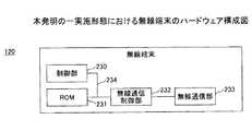
図14は、本発明の一実施形態における無線端末120のハードウェア構成である。無線端末120は、制御部230と、ROM231と、無線通信制御部232と、無線通信部233と、バス234とを有する。<Hardware configuration example of wireless terminal>
FIG. 14 is a hardware configuration of the
制御部230は、無線端末120における通信制御を行う。ROM231は、制御部230が実行するプログラムや、端末IDを記憶する。無線通信制御部232は、無線通信部233を介して、端末IDを含むビーコン信号を送信する。バス234は、上記各部を電気的に接続する。 The
なお、図示しないが、本発明の一実施形態において用いられる管理装置110及びゲートウェイ140は、汎用のコンピュータ又はサーバ装置によって構成され得る。 Although not shown, the
<3.機能>
次に、本発明の一実施形態における無線端末120と、照明装置150と、管理装置110の機能について、図面に基づいて説明する。<3. Function>
Next, functions of the
<無線端末の機能>
図15に例示されるように、本発明の一実施形態における無線端末120は、端末ID記憶部401と、ビーコン信号送信部402とを有する。<Functions of wireless terminal>
As illustrated in FIG. 15, the
端末ID記憶部401は、図14のROM231により実現され、位置管理システム1において無線端末120を識別するための識別子である端末IDを記憶する。端末IDは、任意の文字、数字、記号の組み合わせによって表され得る。例えば、無線端末120が人に付される場合には、端末IDは、人に割当てられた識別番号(例えば、「000535」のような社員番号)であってもよい。 The terminal
ビーコン信号送信部402は、図14の無線通信制御部232及び無線通信部233により主に実現され、端末ID記憶部401に記憶されている端末IDを読み出し、端末IDを含むビーコン信号を、例えば微弱無線により送信する。ビーコン信号送信部402は、例えば、予め決められた時刻又は時間間隔で、定期的にビーコン信号を送信する。また、ビーコン信号送信部402は、人又は外部からの信号に応じて、ビーコン信号を送信してもよい。 The beacon
<照明装置の機能>
本発明の一実施形態における照明装置150は、ビーコン信号受信部405と、装置ID記憶部406と、ID送信部407と、中継部408とを有する。<Function of lighting device>
The
ビーコン信号受信部405は、図11のCPU200、無線通信制御部1206及び無線通信部1208により主に実現され、無線端末120のビーコン信号送信部402から送信されるビーコン信号を受信する。そして、ビーコン信号受信部405は、ビーコン信号に含まれる端末IDを取得し、取得した端末IDをID送信部407に渡す。The beacon
装置ID記憶部406は、図11のROM204により主に実現され、位置管理システム1において照明器具100を識別するための識別子である装置IDを記憶している。装置IDは、任意の文字、数字、記号の組み合わせによって表され得る。例えば、照明器具100が、オフィスの天井に設置される場合には、装置IDは、オフィスの大まかな場所を表す文字列(例えば、C棟20階北エリアの1番目の照明器具を表す「C20N001」)であってもよい。 The device
ID送信部407は、図11のCPU200、無線通信制御部2210及び無線通信部2212により主に実現される。ID送信部407は、ビーコン信号受信部405から端末IDを受け取ると、端末IDと、装置ID記憶部406から読み出した装置IDとを、管理装置110に送信する。なお、ID送信部407は、端末IDと装置IDとを、無線ネットワークにより接続されるゲートウェイ140(及び必要に応じて他の照明器具102)を介して、管理装置110に送信することができる。The
中継部408は、図11のCPU200、無線通信制御部2210及び無線通信部2212により主に実現され、他の照明装置150から送信される端末ID及び装置IDを受信し、さらに他の照明装置又はゲートウェイ140へと転送する。例えば、無線ネットワークがZigBeeにより形成される場合、中継部408は、ZigBeeルータによるネットワークの中継機能を提供できる。The
<管理装置の機能>
本発明の一実施形態における管理装置110は、位置情報記憶部409と、無線端末管理部410とを有する。<Functions of management device>
The
位置情報記憶部409は、照明装置150に記憶されている装置IDと、装置IDの付された照明装置150の設置位置とが関連付けられた、図16に例示される位置情報を記憶している。 The position
装置IDは、照明装置150に付される固有のIDであり、位置は、位置管理システム1が管理対象とする空間内の位置を表す。位置は、例えば、フロア内の基準点に対する二次元座標(X、Y)によって表され得る。また、位置は、例えば、緯度及び経度、建物の番号、建物名、フロア、地名、住所、郵便番号、高度等、物理的な場所を特定可能な任意の情報により表されてもよい。 The device ID is a unique ID assigned to the
無線端末管理部410は、照明装置150から、端末IDと装置IDとを受信すると、受信した装置IDをキーとして位置情報を探索し、対応する位置を読み出す。そして、無線端末管理部410は、読み出した位置と、端末IDと、端末IDを受信した時刻を、図17に例示されるテーブルに格納する。無線端末管理部410は、図17の例に限らず、任意の形式で端末IDを受信してもよい。 When receiving the terminal ID and the device ID from the
また、管理装置110は、一定の周期で照明装置150と通信して動作確認を行ってもよい。例えば照明装置150に異常が発生した場合には、異常が発生したことを検出することが可能になる。また、例えば電源が遮断された状態で、二次電池170が放電し尽して照明部156等に電源供給できなくなった場合に、充電又は収納部157の交換が必要になっていることを検出できる。 In addition, the
管理装置110は、例えば、このようにして格納された無線端末120の位置を用いて、無線端末120を地図上に表示したり、ユーザから指定された位置にある無線端末120の端末IDのリストを出力したりすることができる。 For example, the
<4.動作例>
図18を用いて、本発明の一実施形態における位置管理システム1の動作例を説明する。本実施例では、位置管理システム1は、オフィス内での人(社員)の位置を管理する。人は、無線端末120が取り付けられた、社員証、携帯電話、又は社用PCのような物品を所持してオフィス内を移動する。<4. Example of operation>
An example of the operation of the
以下の例では、ある社員が保持する無線端末120の端末IDが、「000535」であり、社員の近傍に存在する照明装置150の装置IDが「C20N001」であるものとして説明する。また、管理装置110は、図16に例示されるように、装置IDが「C20N001」である照明装置150の設置された位置の情報を含む位置情報を、予め格納しているものとする。 In the following example, it is assumed that the terminal ID of the
社員が、上記した装置IDが付された照明装置150の近傍に移動すると、無線端末120のビーコン信号送信部402は、端末ID記憶部401から、端末ID「000535」を読み出す(ステップS101)。ビーコン信号送信部402は、読み出した端末IDを含むビーコン信号を、微弱無線により近傍の照明装置150に向けて送信する(ステップS102)。 When the employee moves to the vicinity of the
照明装置150のビーコン信号受信部405は、受信したビーコン信号に含まれる端末ID「000535」を、ID送信部407に渡す(ステップS103)。ID送信部407は、装置ID記憶部406から、装置ID「C20N001」を受け取る(ステップS104)。そして、ID送信部407は、端末ID「000535」と装置ID「C20N001」とを、IEEE802.15.4及びZigBeeによる無線ネットワークを介して、管理装置110に送信する(ステップS105)。その後、端末ID及び装置IDは、無線ネットワークを形成する他の照明装置やゲートウェイ140を経由して、管理装置110に伝送される。 The beacon
管理装置110は、照明装置150から端末ID及び装置IDを受信すると、受信した装置IDをキーとして、位置情報記憶部409に記憶されている位置情報を検索し、装置IDに対応する位置を読み出す(ステップS106)。ここでは、図16から、位置「(x1、y1)」が読み出される。そして、無線端末管理部410は、読み出した位置「(x1、y1)」と、端末ID「000535」と、受信日時である「2013/11/21 13:14:00」とを関連付けて位置情報を更新する(ステップS107)。 When the
以上の動作により、本発明の一実施形態における位置管理システム1において、無線端末120を保持する社員の位置が管理される。照明装置150は、二次電池170を有することで、照明器具100への電源が遮断された場合であっても、無線端末120及び管理装置110と通信可能であり、位置管理システム1は無線端末120の位置を管理できる。また、無線端末120は、微弱無線を用いて照明装置150と通信するため、低消費電力である。さらに、照明装置150とゲートウェイ140とは、照明装置150と無線端末120との間で用いられる方式とは異なる無線通信方式により通信するため、電波干渉によるネットワークのスループットの低下を回避できる。 With the above operation, the position of the employee holding the
なお、無線端末120は、微弱無線による無線通信の代わりに、照明装置150とゲートウェイ140によって用いられる、IEEE802.15.4及びZigBeeによる無線通信を行ってもよい。この場合には、無線端末120は、ZigBeeエンドデバイスとして機能する。これにより、照明装置150は、無線端末120と通信するための無線通信制御部1206及び無線通信部1208(図11)を設ける必要がなくなる。その結果、照明装置150は、より低いコストで製造できるようになる。Note that the
以上、実施形態に係る照明装置及び通信システムについて説明したが、本発明は上記実施形態に限定されるものではなく、本発明の範囲内で種々の変形及び改良が可能である。 The lighting device and the communication system according to the embodiment have been described above, but the present invention is not limited to the above embodiment, and various modifications and improvements can be made within the scope of the present invention.
1 位置管理システム
100 照明器具
110 管理装置
120 無線端末
140 ゲートウェイ
150 照明装置
156 照明部
157 収容部
170 二次電池
174 光反射部材
405 ビーコン信号受信部
407 ID送信部
408 中継部DESCRIPTION OF
Claims (8)
Translated fromJapanese受信した前記端末ID及び装置IDを送信する送信部と、
光源からの光を外部に照射する照明部と、
前記受信部及び前記送信部に電力を供給する二次電池と、
前記照明部に着脱可能に設けられ、前記二次電池を収容する収容部と、を有する、
照明装置。A receiver for receiving a terminal ID assigned to the wireless terminal;
A transmission unit for transmitting the received terminal ID and device ID;
An illumination unit that radiates light from a light source to the outside;
A secondary battery for supplying power to the receiver and the transmitter;
Detachably attached to the lighting unit, havinga storage portion for storingthe secondary battery,
Lighting device.
請求項1に記載の照明装置。The accommodating portion accommodates at least one of the receiving portion and the transmitting portion;
The lighting device according to claim 1.
請求項1又は2に記載の照明装置。The housing portion includes a light reflecting member that reflects light from the light source.
The lighting device according to claim 1 or 2.
請求項1から3の何れか一項に記載の照明装置。The receiving unit receives the terminal ID by weak wireless;
The illumination device according to any one of claims 1 to 3.
請求項4に記載の照明装置。The receiving unit receives the terminal ID included in a beacon signal transmitted at regular time intervals;
The lighting device according to claim 4.
請求項4又は5に記載の照明装置。The transmission unit transmits the terminal ID and the device ID by a wireless communication method different from the weak wireless.
The lighting device according to claim 4 or 5.
前記無線端末の位置を管理する管理装置と、を有し、
前記送信部は、前記端末ID及び前記装置IDを前記管理装置に送信する、
通信システム。The illumination device according to any one of claims 1 to 6,
A management device for managing the position of the wireless terminal,
The transmission unit transmits the terminal ID and the device ID to the management device.
Communications system.
請求項7に記載の通信システム。A relay unit that relays the terminal ID and the device ID transmitted from the transmission unit;
The communication system according to claim 7.
Priority Applications (2)
| Application Number | Priority Date | Filing Date | Title |
|---|---|---|---|
| JP2014178969AJP6044608B2 (en) | 2013-12-09 | 2014-09-03 | Lighting device and communication system |
| US14/557,850US9736912B2 (en) | 2013-12-09 | 2014-12-02 | Illumination device and communication system |
Applications Claiming Priority (3)
| Application Number | Priority Date | Filing Date | Title |
|---|---|---|---|
| JP2013254138 | 2013-12-09 | ||
| JP2013254138 | 2013-12-09 | ||
| JP2014178969AJP6044608B2 (en) | 2013-12-09 | 2014-09-03 | Lighting device and communication system |
Publications (3)
| Publication Number | Publication Date |
|---|---|
| JP2015133311A JP2015133311A (en) | 2015-07-23 |
| JP2015133311A5 JP2015133311A5 (en) | 2016-05-19 |
| JP6044608B2true JP6044608B2 (en) | 2016-12-14 |
Family
ID=53272568
Family Applications (1)
| Application Number | Title | Priority Date | Filing Date |
|---|---|---|---|
| JP2014178969AActiveJP6044608B2 (en) | 2013-12-09 | 2014-09-03 | Lighting device and communication system |
Country Status (2)
| Country | Link |
|---|---|
| US (1) | US9736912B2 (en) |
| JP (1) | JP6044608B2 (en) |
Families Citing this family (14)
| Publication number | Priority date | Publication date | Assignee | Title |
|---|---|---|---|---|
| WO2016045611A2 (en)* | 2014-09-25 | 2016-03-31 | Huizhou Light Engine Limited | Solid-state lighting apparatus with detachable module |
| HUE038097T2 (en)* | 2015-01-05 | 2018-09-28 | Schreder | Method for marking luminaires, controller arrangement and luminaire |
| DE102016104484A1 (en)* | 2016-03-11 | 2017-09-14 | Osram Gmbh | Lighting device with communication device |
| DE102016107154A1 (en) | 2016-04-18 | 2017-10-19 | Osram Gmbh | Lighting device with transmission of operating data |
| JP6807557B2 (en)* | 2016-09-29 | 2021-01-06 | パナソニックIpマネジメント株式会社 | Lighting device |
| JP2018074613A (en)* | 2016-10-24 | 2018-05-10 | 富士ゼロックス株式会社 | Electronic device |
| AT15978U1 (en)* | 2016-10-31 | 2018-10-15 | Zumtobel Lighting Gmbh | lamp |
| JP7019177B2 (en)* | 2017-03-03 | 2022-02-15 | 株式会社ホタルクス | Lighting equipment |
| JP7054798B2 (en)* | 2017-12-04 | 2022-04-15 | パナソニックIpマネジメント株式会社 | Lighting equipment |
| WO2019187259A1 (en)* | 2018-03-28 | 2019-10-03 | 日本電産株式会社 | Positioning system, positioning method, and adjustment method for positioning system |
| JP6654767B1 (en)* | 2019-01-07 | 2020-02-26 | 株式会社Moyai | LED lighting system |
| JP7260146B2 (en)* | 2019-03-05 | 2023-04-18 | アイリスオーヤマ株式会社 | LED lighting device |
| JP7194052B2 (en)* | 2019-03-18 | 2022-12-21 | 川崎車両株式会社 | lighting equipment |
| JP2025039346A (en)* | 2023-09-08 | 2025-03-21 | パナソニックIpマネジメント株式会社 | Gateway device, communication system, communication method, and program |
Family Cites Families (35)
| Publication number | Priority date | Publication date | Assignee | Title |
|---|---|---|---|---|
| JP3003857U (en)* | 1994-03-18 | 1994-11-01 | 株式会社マトイ | Desk lamp with fire detector and fire alarm |
| JP3087026B2 (en)* | 1997-04-10 | 2000-09-11 | 株式会社キクテック | Pedestrian crossing lighting system |
| US7110783B2 (en)* | 2002-04-17 | 2006-09-19 | Microsoft Corporation | Power efficient channel scheduling in a wireless network |
| US8280398B2 (en) | 2004-03-03 | 2012-10-02 | Nec Corporation | Positioning system, positioning method, and program thereof |
| JP2005347827A (en)* | 2004-05-31 | 2005-12-15 | Navitime Japan Co Ltd | Positional information transmission unit and positional information providing system |
| EP1760013A4 (en)* | 2004-06-25 | 2011-05-04 | Nec Corp | Article position management system, article position management method, terminal device, server, and article position management program |
| JP4037857B2 (en)* | 2004-09-28 | 2008-01-23 | 有限会社タック リサーチ | LED lighting device |
| JP4650407B2 (en)* | 2006-12-12 | 2011-03-16 | ソニー株式会社 | Wireless processing system, wireless processing method, and wireless electronic device |
| ES2659746T3 (en)* | 2007-05-24 | 2018-03-19 | Philips Lighting Holding B.V. | System and method to automatically create a given atmosphere by controlling the contributions of perceptible sensory stimulus media |
| JP2009017267A (en)* | 2007-07-05 | 2009-01-22 | Ricoh Co Ltd | LIGHTING SYSTEM, LIGHTING CONTROL DEVICE, AND WIRELESS COMMUNICATION DEVICE |
| JP2009283312A (en)* | 2008-05-22 | 2009-12-03 | Toshiba Corp | Lighting control system |
| JP5125805B2 (en)* | 2008-06-25 | 2013-01-23 | Necライティング株式会社 | Home appliance control system, home appliance, and home appliance control method |
| US8598993B2 (en)* | 2008-08-15 | 2013-12-03 | Homerun Holdings Corporation | Method for wiring devices in a structure using a wireless network |
| CA2957199C (en)* | 2008-11-26 | 2019-01-08 | Wireless Environment, Llc | Wireless lighting devices and applications |
| US10706383B2 (en)* | 2010-07-16 | 2020-07-07 | Walmart Apollo, Llc | Method and apparatus pertaining to module-based scanning of RFID tags |
| JP6041873B2 (en)* | 2011-07-07 | 2016-12-14 | 東莞巨揚電器有限公司 | LED lighting |
| JP5983229B2 (en) | 2012-03-09 | 2016-08-31 | 株式会社リコー | Distribution apparatus, position management system, distribution method, and program |
| JP6064507B2 (en) | 2012-03-14 | 2017-01-25 | 株式会社リコー | Distribution apparatus, position management system, distribution method, and program |
| JP2013206853A (en)* | 2012-03-29 | 2013-10-07 | Toshiba Lighting & Technology Corp | Lighting system |
| JP5962211B2 (en) | 2012-05-25 | 2016-08-03 | 株式会社リコー | POSITION INFORMATION MANAGEMENT SYSTEM, POSITION INFORMATION MANAGEMENT METHOD, AND MANAGEMENT SERVER |
| JP5983035B2 (en)* | 2012-05-29 | 2016-08-31 | 株式会社リコー | Communication apparatus and communication system |
| JP6167566B2 (en) | 2012-05-30 | 2017-07-26 | 株式会社リコー | COMMUNICATION DEVICE, POSITION INFORMATION MANAGEMENT SYSTEM, AND POSITION INFORMATION MANAGEMENT METHOD |
| JP6051603B2 (en) | 2012-06-07 | 2016-12-27 | 株式会社リコー | Radio wave range display device, radio wave range display method, and radio wave range display program |
| JP6225461B2 (en) | 2012-06-12 | 2017-11-08 | 株式会社リコー | Lighting device and position information management system |
| JP2013257212A (en) | 2012-06-12 | 2013-12-26 | Ricoh Co Ltd | Light device, communication device and positional information management system |
| JP6179073B2 (en) | 2012-06-12 | 2017-08-16 | 株式会社リコー | Lighting fixture and position information management system |
| JP6171512B2 (en) | 2012-06-12 | 2017-08-02 | 株式会社リコー | Lighting device and position information management system |
| JP6142497B2 (en) | 2012-06-20 | 2017-06-07 | 株式会社リコー | Distribution device, communication terminal, and distribution system |
| JP6175820B2 (en) | 2012-06-27 | 2017-08-09 | 株式会社リコー | Communication apparatus and communication system |
| JP6187052B2 (en)* | 2012-09-12 | 2017-08-30 | 株式会社リコー | Information management system, wireless terminal and surrounding environment management method |
| JP6268824B2 (en) | 2012-09-14 | 2018-01-31 | 株式会社リコー | Communication system, communication method, and information processing apparatus |
| JP2014064198A (en) | 2012-09-21 | 2014-04-10 | Ricoh Co Ltd | Receiving system, position management system, and receiving method |
| JP6252720B2 (en) | 2012-09-21 | 2017-12-27 | 株式会社リコー | Distribution system, distribution method, and program |
| JP2014064199A (en) | 2012-09-21 | 2014-04-10 | Ricoh Co Ltd | Communication terminal, communication method, and program |
| JP2014077777A (en) | 2012-09-21 | 2014-05-01 | Ricoh Co Ltd | Communication terminal, communication method and program |
- 2014
- 2014-09-03JPJP2014178969Apatent/JP6044608B2/enactiveActive
- 2014-12-02USUS14/557,850patent/US9736912B2/ennot_activeExpired - Fee Related
Also Published As
| Publication number | Publication date |
|---|---|
| US20150163887A1 (en) | 2015-06-11 |
| US9736912B2 (en) | 2017-08-15 |
| JP2015133311A (en) | 2015-07-23 |
Similar Documents
| Publication | Publication Date | Title |
|---|---|---|
| JP6044608B2 (en) | Lighting device and communication system | |
| US9172405B2 (en) | Light device and positional information management system | |
| JP6171512B2 (en) | Lighting device and position information management system | |
| JP5228140B1 (en) | Wireless control system | |
| US10966305B2 (en) | Integrated antenna assemblies for light fixtures | |
| JP6115030B2 (en) | Lighting device and position information management system | |
| US20130234595A1 (en) | Emergency Lighting Device | |
| US9301090B2 (en) | Light device, communication unit and positional information management system | |
| CN113557388A (en) | Wireless power system technology implemented in lighting infrastructure | |
| EP3622672A1 (en) | Lighting control with location based communication | |
| US20130329423A1 (en) | Lighting fixture and positional information management system | |
| US9131560B2 (en) | Portable lamp system | |
| JP2015109030A (en) | COMMUNICATION SYSTEM, COMMUNICATION METHOD, AND LIGHTING DEVICE | |
| JP2025109782A (en) | Management system, lighting equipment and wireless tag | |
| JP2018205323A (en) | Lighting device and position information system | |
| JP6387619B2 (en) | LIGHTING DEVICE, POSITION INFORMATION SYSTEM, AND COMMUNICATION CONTROL METHOD | |
| JP6488947B2 (en) | Lighting system | |
| JP6627940B2 (en) | Position management system and position management method | |
| JP6003264B2 (en) | Lighting device and position information management system | |
| JP7418880B2 (en) | Luminaires and lighting systems | |
| JP6455563B2 (en) | Lighting device and position information management system | |
| JP2017041415A (en) | Lighting system | |
| JP6562201B2 (en) | Lighting device | |
| JP2019061903A (en) | Lighting apparatus and lighting system | |
| CN120529270A (en) | Data concentration device and data transmission system |
Legal Events
| Date | Code | Title | Description |
|---|---|---|---|
| A521 | Request for written amendment filed | Free format text:JAPANESE INTERMEDIATE CODE: A523 Effective date:20160328 | |
| A621 | Written request for application examination | Free format text:JAPANESE INTERMEDIATE CODE: A621 Effective date:20160328 | |
| A871 | Explanation of circumstances concerning accelerated examination | Free format text:JAPANESE INTERMEDIATE CODE: A871 Effective date:20160328 | |
| A975 | Report on accelerated examination | Free format text:JAPANESE INTERMEDIATE CODE: A971005 Effective date:20160531 | |
| A131 | Notification of reasons for refusal | Free format text:JAPANESE INTERMEDIATE CODE: A131 Effective date:20160607 | |
| A521 | Request for written amendment filed | Free format text:JAPANESE INTERMEDIATE CODE: A523 Effective date:20160715 | |
| TRDD | Decision of grant or rejection written | ||
| A01 | Written decision to grant a patent or to grant a registration (utility model) | Free format text:JAPANESE INTERMEDIATE CODE: A01 Effective date:20161018 | |
| A61 | First payment of annual fees (during grant procedure) | Free format text:JAPANESE INTERMEDIATE CODE: A61 Effective date:20161031 | |
| R151 | Written notification of patent or utility model registration | Ref document number:6044608 Country of ref document:JP Free format text:JAPANESE INTERMEDIATE CODE: R151 |