JP6044426B2 - Information operation display system, display program, and display method - Google Patents
Information operation display system, display program, and display methodDownload PDFInfo
- Publication number
- JP6044426B2 JP6044426B2JP2013077240AJP2013077240AJP6044426B2JP 6044426 B2JP6044426 B2JP 6044426B2JP 2013077240 AJP2013077240 AJP 2013077240AJP 2013077240 AJP2013077240 AJP 2013077240AJP 6044426 B2JP6044426 B2JP 6044426B2
- Authority
- JP
- Japan
- Prior art keywords
- display
- dimensional
- coordinate position
- dimensional coordinate
- operation target
- Prior art date
- Legal status (The legal status is an assumption and is not a legal conclusion. Google has not performed a legal analysis and makes no representation as to the accuracy of the status listed.)
- Expired - Fee Related
Links
Images


Classifications
- G—PHYSICS
- G06—COMPUTING OR CALCULATING; COUNTING
- G06F—ELECTRIC DIGITAL DATA PROCESSING
- G06F3/00—Input arrangements for transferring data to be processed into a form capable of being handled by the computer; Output arrangements for transferring data from processing unit to output unit, e.g. interface arrangements
- G06F3/01—Input arrangements or combined input and output arrangements for interaction between user and computer
- G06F3/048—Interaction techniques based on graphical user interfaces [GUI]
- G06F3/0487—Interaction techniques based on graphical user interfaces [GUI] using specific features provided by the input device, e.g. functions controlled by the rotation of a mouse with dual sensing arrangements, or of the nature of the input device, e.g. tap gestures based on pressure sensed by a digitiser
- G06F3/0488—Interaction techniques based on graphical user interfaces [GUI] using specific features provided by the input device, e.g. functions controlled by the rotation of a mouse with dual sensing arrangements, or of the nature of the input device, e.g. tap gestures based on pressure sensed by a digitiser using a touch-screen or digitiser, e.g. input of commands through traced gestures
- G06F3/04883—Interaction techniques based on graphical user interfaces [GUI] using specific features provided by the input device, e.g. functions controlled by the rotation of a mouse with dual sensing arrangements, or of the nature of the input device, e.g. tap gestures based on pressure sensed by a digitiser using a touch-screen or digitiser, e.g. input of commands through traced gestures for inputting data by handwriting, e.g. gesture or text
- G—PHYSICS
- G06—COMPUTING OR CALCULATING; COUNTING
- G06F—ELECTRIC DIGITAL DATA PROCESSING
- G06F3/00—Input arrangements for transferring data to be processed into a form capable of being handled by the computer; Output arrangements for transferring data from processing unit to output unit, e.g. interface arrangements
- G06F3/01—Input arrangements or combined input and output arrangements for interaction between user and computer
- G06F3/017—Gesture based interaction, e.g. based on a set of recognized hand gestures
- G—PHYSICS
- G06—COMPUTING OR CALCULATING; COUNTING
- G06F—ELECTRIC DIGITAL DATA PROCESSING
- G06F3/00—Input arrangements for transferring data to be processed into a form capable of being handled by the computer; Output arrangements for transferring data from processing unit to output unit, e.g. interface arrangements
- G06F3/01—Input arrangements or combined input and output arrangements for interaction between user and computer
- G06F3/03—Arrangements for converting the position or the displacement of a member into a coded form
- G06F3/0304—Detection arrangements using opto-electronic means
- G—PHYSICS
- G06—COMPUTING OR CALCULATING; COUNTING
- G06F—ELECTRIC DIGITAL DATA PROCESSING
- G06F3/00—Input arrangements for transferring data to be processed into a form capable of being handled by the computer; Output arrangements for transferring data from processing unit to output unit, e.g. interface arrangements
- G06F3/01—Input arrangements or combined input and output arrangements for interaction between user and computer
- G06F3/03—Arrangements for converting the position or the displacement of a member into a coded form
- G06F3/041—Digitisers, e.g. for touch screens or touch pads, characterised by the transducing means
- G06F3/042—Digitisers, e.g. for touch screens or touch pads, characterised by the transducing means by opto-electronic means
- G06F3/0425—Digitisers, e.g. for touch screens or touch pads, characterised by the transducing means by opto-electronic means using a single imaging device like a video camera for tracking the absolute position of a single or a plurality of objects with respect to an imaged reference surface, e.g. video camera imaging a display or a projection screen, a table or a wall surface, on which a computer generated image is displayed or projected
- G—PHYSICS
- G06—COMPUTING OR CALCULATING; COUNTING
- G06F—ELECTRIC DIGITAL DATA PROCESSING
- G06F2203/00—Indexing scheme relating to G06F3/00 - G06F3/048
- G06F2203/041—Indexing scheme relating to G06F3/041 - G06F3/045
- G06F2203/04101—2.5D-digitiser, i.e. digitiser detecting the X/Y position of the input means, finger or stylus, also when it does not touch, but is proximate to the digitiser's interaction surface and also measures the distance of the input means within a short range in the Z direction, possibly with a separate measurement setup
- G—PHYSICS
- G06—COMPUTING OR CALCULATING; COUNTING
- G06F—ELECTRIC DIGITAL DATA PROCESSING
- G06F3/00—Input arrangements for transferring data to be processed into a form capable of being handled by the computer; Output arrangements for transferring data from processing unit to output unit, e.g. interface arrangements
- G06F3/01—Input arrangements or combined input and output arrangements for interaction between user and computer
- G06F3/03—Arrangements for converting the position or the displacement of a member into a coded form
- G06F3/041—Digitisers, e.g. for touch screens or touch pads, characterised by the transducing means
- G06F3/0416—Control or interface arrangements specially adapted for digitisers
Landscapes
- Engineering & Computer Science (AREA)
- General Engineering & Computer Science (AREA)
- Theoretical Computer Science (AREA)
- Human Computer Interaction (AREA)
- Physics & Mathematics (AREA)
- General Physics & Mathematics (AREA)
- Multimedia (AREA)
- User Interface Of Digital Computer (AREA)
Description
Translated fromJapanese本発明は、情報操作表示システム、表示プログラム及び表示方法に関する。 The present invention relates to an information operation display system, a display program, and a display method.
近年、現実の物体にプロジェクタを使ってバーチャル画像を投影させ、現実の物体に関連付けられた注釈やメニューなどを提示する拡張現実技術が知られている。また、このような拡張現実技術において、手指などの操作対象物によるジェスチャを検出し、バーチャル画像とのインタラクションを実現するユーザインタフェース技術が利用されている。 In recent years, augmented reality technology that projects a virtual image onto a real object using a projector and presents an annotation, a menu, or the like associated with the real object is known. In such augmented reality technology, a user interface technology that detects a gesture caused by an operation target such as a finger and realizes an interaction with a virtual image is used.
このような操作対象物のジェスチャを検出する手法として、カメラで撮影された操作対象物を含む撮影画像を用いて、操作対象物の3次元座標を計測し、3次元座標の変化からジェスチャを検出する手法が知られている。 As a technique for detecting a gesture of such an operation target, a three-dimensional coordinate of the operation target is measured using a captured image including the operation target photographed by a camera, and the gesture is detected from a change in the three-dimensional coordinate. There is a known technique to do this.
しかし、従来技術では、撮影画像を用いて操作対象物の3次元位置を計測するので、操作対象物がカメラの視野範囲から外れて撮影画像に写らなくなると、操作対象物の3次元位置を計測できない場合がある。このような場合には、操作対象物のジェスチャを検出することができず、操作性が低下する。 However, in the prior art, since the three-dimensional position of the operation target is measured using the captured image, the three-dimensional position of the operation target is measured when the operation target is out of the camera field of view and does not appear in the captured image. There are cases where it is not possible. In such a case, the gesture of the operation target cannot be detected, and the operability is deteriorated.
一つの側面では、操作性を向上させる情報操作表示システム、表示プログラム及び表示方法を提供することを目的とする。 An object of one aspect is to provide an information operation display system, a display program, and a display method that improve operability.
一つの案の情報操作表示システムは、カメラとプロジェクタと情報処理装置とを有する情報操作表示システムであって、前記情報処理装置は、前記カメラにより撮像された撮影画像を取得する取得部と、前記取得部によって取得された撮影画像に含まれる操作対象物の3次元座標位置を計測する計測部と、前記計測部によって計測された3次元座標位置と、前記カメラにより定まる、操作対象物の3次元座標位置が計測可能な3次元領域の境界との距離に基づいて、前記操作対象物に画像を表示するように前記プロジェクタを制御する表示部と、を有することを特徴とする。 One proposed information operation display system is an information operation display system including a camera, a projector, and an information processing device, wherein the information processing device acquires an image captured by the camera; and A measurement unit that measures the three-dimensional coordinate position of the operation target included in the captured image acquired by the acquisition unit, the three-dimensional coordinate position measured by the measurement unit, and the three-dimensional of the operation target determined by the camera And a display unit that controls the projector so as to display an image on the operation target based on a distance from a boundary of a three-dimensional region in which a coordinate position can be measured.
一実施形態によれば、操作性を向上させることができる。 According to one embodiment, operability can be improved.
以下に、本願の開示する情報操作表示システム、表示プログラム及び表示方法の実施例を、図面に基づいて詳細に説明する。なお、この実施例により開示技術が限定されるものではない。そして、各実施例は、処理内容を矛盾させない範囲で適宜組み合わせることが可能である。 Embodiments of an information operation display system, a display program, and a display method disclosed in the present application will be described below in detail with reference to the drawings. The disclosed technology is not limited by this embodiment. Each embodiment can be appropriately combined within a range in which processing contents are not contradictory.
[情報操作表示システムの構成]
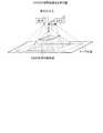
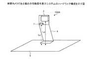
図1は、情報操作表示システムの全体の概略構成の一例を示す図である。図1に示すように、情報操作表示システム100は、カメラ1、2と、プロジェクタ(表示装置)3と、情報処理装置10とを有する。情報処理装置10は、カメラ1、2およびプロジェクタ3とネットワーク(図示省略)を介して通信可能に接続される。プロジェクタ3は、所定の投影面上に画像を投影する。カメラ1、2は、投影面上に投影された画像と該画像上に置かれた操作対象物(例えば、操作者の手や指)との画像を撮影する。そして、情報処理装置10は、カメラ1、2により撮影された時系列の画像から、操作対象物の三次元位置を算出する。[Configuration of information operation display system]
FIG. 1 is a diagram illustrating an example of a schematic configuration of the entire information operation display system. As shown in FIG. 1, the information
その後、情報処理装置10は、算出された操作対象物の三次元位置に基づき、ドキュメントなどの被操作対象物に対する操作を判断する。例えば、情報処理装置10は、ドキュメントのどの情報がタッチ(選択)されたのか、またタッチ(選択)が解除されたのかなどを判断する。なお、カメラ1、2やプロジェクタ3への接続に用いられるネットワークは、有線または無線を問わず、Local Area Network(LAN)やVirtual Private Network(VPN)などの任意の通信網が挙げられる。 Thereafter, the
また、カメラ1、2のシャッタータイミングは必ずしも同じでなくてもよい。つまり、カメラ1、2は非同期カメラであってよい。さらに、情報操作表示システム100は、カメラを3台以上有していてもよい。また、プロジェクタ3と、情報処理装置10とはネットワークを介して接続されるものとしたが、接続されていなくてもよい。なお、カメラ1、2による撮影の対象物は、投影されたドキュメントの操作者の手や指である場合を例に説明するが、これに限定されない。例えば、対象物は、ペンや棒などであってもよい。 The shutter timings of the
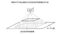
次に、図2を用いて、実施例1にかかる情報操作表示システム100のハードウェア構成について説明する。図2は、ステレオカメラである場合の情報操作表示システムのハードウェア構成を示す図である。図2に示すように、情報操作表示システム100では、テーブル5上に設置された装置でステレオカメラとして2台のカメラ1、2およびプロジェクタ3が固定台4により固定されている。2台のカメラ1、2およびプロジェクタ3は、有線または無線でコンピュータに接続されている。 Next, the hardware configuration of the information
各カメラ1、2は、テーブル面からLcの高さに、テーブル面と並行に設置されており、2台のカメラ1、2の距離はDである。プロジェクタ3は、2台のカメラ1、2の中央にテーブル面からLpの高さで設置されている。なお、Lc、Lp、Dは実空間上での長さであり、単位はたとえばmmである。カメラ1、2は、水平方向画角αch、垂直方向画角αcvを持ち、2台ともこれらの値や焦点距離、撮影可能な画像サイズは同じである。プロジェクタ3は、水平方向にαph、垂直方向にαpvの画角を持つ。カメラ1、2、プロジェクタ3ともに水平画角のほうが垂直画角よりも大きいものとする。 The
ここで、情報操作表示システム100の使用例について説明する。例えば、情報操作表示システム100の使用例として、プロダクトデザインへの確認がある。色、パッケージデザインが決まっていない製品モックアップをテーブルの上に置き、プロジェクタ3により製品モックアップに色を重畳表示したり、絵を付けたりして、製品パッケージのデザインを実物で検討することができる。 Here, a usage example of the information
また、例えば、情報操作表示システム100では、手指のジェスチャを認識することにより直感的な操作も実現できる。例えば、モックアップを指で触り、触った箇所にプロジェクタ3で色を表示していくことで、絵の描画ができる。さらに空中の3次元空間を使ったジェスチャにより、表示内容を制御することができる。例えば、空中で手を左右に振るジェスチャにより、表示色を赤→黄色→緑→青→紫といったように別の色に切り替えることができる。また、手を上下に移動することにより、表示色の濃度を変えることもできる。 Further, for example, in the information
[情報処理装置の構成]
次に、図3を用いて、実施例1にかかる情報処理装置10について説明する。図3は、情報処理装置の全体構成を示す図である。図3に示すように、情報処理装置10は、通信I/F(インタフェース)部11と、表示部12と、入力部13と、記憶部14と、制御部15とを有する。[Configuration of information processing device]
Next, the
通信I/F部11は、他の装置との間で通信制御を行うインタフェースである。通信I/F部11は、ネットワークを介して各種情報を受信する。例えば、通信I/F部11は、カメラ1、2からドキュメントや操作対象物を撮影した画像を受信する。かかる通信I/F部11の一態様としては、LANカードなどのネットワークインタフェースカードが挙げられる。 The communication I / F unit 11 is an interface that controls communication with other devices. The communication I / F unit 11 receives various information via a network. For example, the communication I / F unit 11 receives an image obtained by photographing a document or an operation target from the
表示部12は、各種情報を表示する表示デバイスである。例えば、表示部12としては、LCD(Liquid Crystal Display)やCRT(Cathode Ray Tube)などの表示デバイスが挙げられる。表示部12は、各種情報を表示する。例えば、表示部12は、記憶部14に格納される各情報を表示する。 The
入力部13は、各種の情報を入力する入力デバイスである。例えば、入力部13としては、マウス、キーボード、タッチセンサなどの入力デバイスが挙げられる。入力部13は、情報処理装置10のユーザから入力された情報を制御部15へ出力する。例えば、入力部13は、後記する、3次元計測可能領域情報141、3次元座標位置情報142、アラートパターン情報143などの元となる情報を受け付けると、制御部15へ出力し、制御部15経由で記憶部14に記憶させる。 The
記憶部14は、ハードディスク、SSD(Solid State Drive)、光ディスクなどの不揮発性の記憶装置である。なお、記憶部14は、RAM(Random Access Memory)、フラッシュメモリ、NVSRAM(Non Volatile Static Random Access Memory)などのデータを書き換え可能な半導体メモリであってもよい。 The
記憶部14は、制御部15で実行されるOS(Operating System)や各種プログラムを記憶する。また、記憶部14は、プログラムで用いられる各種データやプログラムにより生成された各種データを記憶する。例えば、記憶部14は、3次元計測可能領域情報141と、3次元座標位置情報142と、アラートパターン情報143とを記憶する。 The
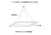
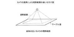
3次元計測可能領域情報141は、操作対象物の3次元座標位置が計測可能な3次元計測可能領域の3次元座標に関する情報である。この3次元計測可能領域情報141は、予め規定されて記憶される情報である。ここで、図4を用いて、3次元計測可能領域について説明する。図4は、3次元計測可能領域を示す図である。図4に示すように、カメラ1、2からテーブル面までの3次元の視野は、四角錐の形状になり、四角錐内の一定エリアのみが3次元計測可能領域となる。実空間の3次元座標系は、また、図4で示すようにカメラ1、カメラ2の設置位置の中央の点を原点(0,0,0)とし、左右方向をX軸、奥行方向をY軸、上下方向をZ軸とする。3次元座標の単位は、たとえばmmである。また、X軸がカメラの水平画角、Y軸がカメラの垂直画角に対応する。なお、3次元計測可能領域の規定方法については、後に図8を用いて詳述する。 The three-dimensional
また、情報操作表示システム100全体のサイズを小さくするため、高さを低くしようとする場合には、広角のカメラを用いることが有効である。図5Aおよび図5Bに、画角がそれずれ異なるカメラの視野範囲を示す。図5Aおよび図5Bに示すように、テーブル面での視野範囲を同じ大きさにしようとすると、図5Aに例示するカメラの画角の狭いカメラに比べて、図5Bに例示する画角の広いカメラではカメラの高さを低くすることができる。しかし、広角のカメラでは、ジェスチャを行う手指の高さによって視野範囲が大きく変わる。このことは、ユーザがジェスチャを行う上で、ジェスチャ視野範囲、すわなち、3次元計測可能領域から外れやすくなってしまう。また、広角なカメラほど、ユーザは3次元計測可能な領域を認知しづらくなる。 In order to reduce the overall size of the information
3次元座標位置情報142は、後述する計測部152によって計測された操作対象物である手指の3次元座標位置に関する情報である。また、アラートパターン情報143は、プロジェクタ3により表示される、3次元計測可能領域の境界に手指が近づいたことを知らせるアラートパターンの形状や色などに関する情報である。このアラートパターン情報143は、後述する表示部153がアラートパターンを表示する際に参照される情報である。 The three-dimensional coordinate
制御部15は、情報処理装置10を制御するデバイスである。制御部15としては、CPU(Central Processing Unit)、MPU(Micro Processing Unit)等の電子回路や、ASIC(Application Specific Integrated Circuit)、FPGA(Field Programmable Gate Array)等の集積回路を採用できる。制御部15は、各種の処理手順を規定したプログラムや制御データを格納するための内部メモリを有し、これらによって種々の処理を実行する。例えば、制御部15は、各種のプログラムが動作しており、各種の処理部として機能する。制御部15は、取得部151と、計測部152と、表示部153とを有する。 The
取得部151は、カメラ1、2により撮像された撮影画像を取得する。例えば、取得部151は、毎秒所定回(例えば、60回)2台のカメラ1、2からの画像を取得する。取得部151は、図6Aに例示するような画像を2台のカメラ1、2から取得する。図6Aの(a)は、カメラ1により撮影された撮影画像であり、図6Aの(b)は、カメラ2により撮影された撮影画像である。図6Aの(a)に例示する撮影画像と、図6Aの(b)に例示する撮影画像とでは、手指とプロジェクタにより投影された画像との位置関係が異なる。 The
そして、取得部151は、撮影画像を取得した後、取得した撮影画像の中から手指領域のみを抽出する。例えば、取得部151は、画像における各画素の色情報、および抽出するための色に関する条件に基づき、肌色領域を検出し、撮影画像の中から手指領域のみを抽出する。 And the
例えば、対象物が手である場合には、取得部151は、手の色を示す色情報と、取得した画像における各画素の色とに基づき、手の領域を検出する。色情報としては、例えば、以下の式(1)および式(2)を用いる。なお、式(1)は、画像の画素値がHSV表色系で示されたときの色相(H)の値に関する条件を示す。式(2)は、HSV表色系で示されたときの彩度(S)の値に関する条件を示す。 For example, when the object is a hand, the

そして、取得部151は、検出した対象物の領域の面積を算出する。例えば、取得部151は、取得した画像における画素のうち、色に関する条件に該当する画素に「1(黒)」を設定し、該当しない画素に「0(白)」を設定することで、二値画像を生成する。そして、取得部151は、その領域の画素数を面積として検出する。なお、画像における色がHSV表色系以外の表色系で表現されている場合、取得部151は、画像における色をHSV表色系へ変換する。 And the
図6Aおよび図6Bは、対象物の領域を抽出する処理を説明する図である。図6Aは、取得した画像を示す図である。なお、図6Aは、2つのカメラ1、2から各々取得した画像のうちの一方である。ただし、取得部151は、各々の画像に対して、同様の処理を実行することで、各々の画像における操作対象物の領域を抽出する。例えば、図6Aに示す画像において、手6、物体7、物体8および背景が撮影されているとする。ここで、手6と、物体7と、物体8とは、実際の画像において各々異なる色を有するものとする。 6A and 6B are diagrams for explaining processing for extracting a region of an object. FIG. 6A is a diagram illustrating an acquired image. FIG. 6A shows one of the images acquired from the two
図6Bは、図6Aに対応する二値画像である。二値画像においては、手6に対応する手領域60のみが示されている。つまり、図6Aの画像に対して、手領域60を検出する処理を実行することで、図6Aの画像において色に関する条件に合致する画素からなる領域が、手領域60として二値画像に表される。 FIG. 6B is a binary image corresponding to FIG. 6A. In the binary image, only the
そして、取得部151は、対象物の領域の形状に基づき、例えば、特徴点として、指の先端部分を構成する画素を検出する。具体的には、図6Bにおける手領域60の形状を利用して、特徴点を検出する。そして、取得部151は、各々の二値画像における特徴点の座標(x,y)を取得する。 And the
ここで、特徴点の検出においては、指の先端の形状モデルと、抽出した手領域60の形状とのパターンマッチングが利用される。また、手領域60の形状を認識するとともに、指領域を抽出し、指領域の傾きを利用する方法が用いられてもよい。例えば、特開2003−346162号公報に開示の技術が利用される。 Here, in the feature point detection, pattern matching between the shape model of the tip of the finger and the shape of the extracted
計側部152は、取得部151によって取得された撮影画像に含まれる操作対象物の3次元座標位置を計測する。例えば、計測部152は、手指の3次元座標(x,y,z)を検出する。この座標は手指のうち、特定の指先、たとえば人差し指の先端の座標でもよい。また、すべての指先について複数個座標を検出してもよい。また、複数個の指先の座標から求めた手の甲や掌の画像中の中心の座標でもよい。手指の3次元座標の検出方法としては、ステレオ視による方法がある。この場合には、計測部152は、まず撮影画像のカメラ座標系における手指の座標を検出する。 The
例えば、計測部152は、カメラ1の人差し指座標F1b=(X1b,Y1b)、カメラ2の人差し指座標F2b=(X2b,Y2b)を検出する。そして、X2bとX1bとの距離をもとに三角測量の原理で3次元座標を求める。そして、計測部152は、検出した手指領域の形状や過去の手指領域の形状からの変化をもとにジェスチャを検出し、所定のジェスチャであるか否かを判定する。この結果、計測部152は、所定のジェスチャであると判定した場合、つまり、操作に関係するジェスチャであると判定した場合には、アラートパターンを表示する旨の指示を表示部153に通知する。 For example, the
また、計測部152は、検出した手指の3次元座標をもとに、次のフレームでの手指の3次元座標(x’,y’,z’)を予測してもよい。計測部152は、過去の手指の3次元座標位置と現在の手指の3次元座標位置とを比較し、該3次元座標位置の変化に基づいて、手指の3次元座標位置を予測する。例えば、検出した手指の情報をもとに表示を行う場合、画像の撮影時刻から表示時刻までに時差が発生する。この間に手指が移動することがあるため、手指3次元座標を予測し、移動先に合わせた表示を行うと、意図した位置にずれなく後述するアラートパターンを表示することができる。予測方法としては、取得した3次元座標(x,y,z)および過去のフレームにおける手指の3次元座標(x,y,z)とその取得時刻から、時刻から座標に変換する近似式を求め、次のフレームの時刻に表示すべき位置を予測する。 Further, the
続いて、計測部152は、手指の3次元座標が3次元計測可能領域のどこに存在しているかを判定する。ここで、3次元計測可能領域の規定方法を以下で説明する。図8に例示する3次元座標系において、カメラ1の設置座標が(−D/2,0,0)、カメラ2の設置座標は(D/2,0,0)である。さらに、カメラの水平画角αch、垂直画角αcvから、レンズからのZ軸方向の距離zにおける横視野範囲Rh(z)がRh(z)=2×z×tan(αch/2)、縦視野範囲Rv(z)はRv(z)=2×z×tan(αcv/2)とあらわせる。なお、tan(θ)は、角度θにおける正接の値を示す。3次元計測可能領域は、2台のカメラ1、2の視野範囲が重なる場所としてあらわせるため、レンズからのZ軸方向の距離zにおけるX,Y方向の3次元計測可能領域は、以下に示すようになる。X方向の3次元計測可能領域は、「X座標最小値 minX(z)=−(Rh(z)−D)/2」、「X座標最大値 maxX(z)=(Rh(z)−D)/2」の範囲の座標としてあらわせる。また、Y方向の3次元計測可能領域は、「Y座標最小値 minY(z)=−Rv(z)/2」、「Y座標最小値 minY(z)=Rv(z)/2」の範囲の座標としてあらわせる。また、3次元計測可能領域のZ座標最大値は、テーブル面となるため、「Z座標最大値 maxZ=Lc」となる。Subsequently, the
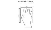
ここで、手指がカメラ1、2に近づきすぎると、手指全体がカメラに写らずジェスチャとして認識できなくなるため、3次元計測可能領域のZ座標の最小値minZは、手が写る最小の距離とする。手のサイズを図7で示すようにX方向Sx、Y方向Syとすると、撮影画像の短辺Y方向の視野範囲がSyと同一になるZ座標がminZとなるためRv(minZ)=Syとなり、これを解くと「Z座標最小値 minZ=Sy/(2×tan(αcv/2))」となる。図7は、手の検出サイズを示す図である。Here, if the finger is too close to the
このようなX,Y,Zの最小値、最大値を持つ3次元計測可能領域を示す立体とその対応座標は図8のようになる。以上のようにして、手指の3次元座標(x,y,z)が与えられると、3次元計測可能領域minX(z),maxX(z),minY(z),maxY(z),minZ,maxZが決定される。図8は、3次元計測可能領域の3次元座標を示す図である。 A solid representing such a three-dimensional measurable region having the minimum and maximum values of X, Y, and Z and its corresponding coordinates are as shown in FIG. As described above, when the three-dimensional coordinates (x, y, z) of the finger are given, the three-dimensional measurable region minX (z), maxX (z), minY (z), maxY (z), minZ, maxZ is determined. FIG. 8 is a diagram illustrating the three-dimensional coordinates of the three-dimensional measurable region.
表示部153は、計測部152によって計測された3次元座標位置と、カメラ1、2により定まる、操作対象物の3次元座標位置が計測可能な3次元領域の境界との距離に基づいて、操作対象物に画像を表示するようにプロジェクタ3を制御する。表示部153は、計測部152によりジェスチャが検出された後、後述するように、アラートパターンの生成、表示処理を行う。アラートパターンの表示有無は、ジェスチャの状態やアプリケーションの状態によって切り替えてもよい。例えば、アラートパターンは5本の指をすべて開いている場合にのみ表示することができる。また、アプリケーションが対象物、たとえば製品モックアップに色を表示している場合にのみアラートパターンを表示するようにすることもできる。ここでアラートパターンの表示を行わないと判定された場合には、以後の処理は行われない。 The
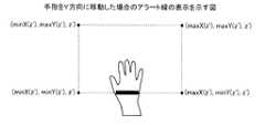
例えば、まず、表示部153は、3次元計測可能領域minX(z),maxX(z),minY(z),maxY(z),minZ,maxZを用いて、アラートパターンを生成する。3次元エリア上で手指を動かした場合のアラートパターンとその表示位置の例について図9A〜図11Cを用いて説明する。図9A〜図9Cは、手指をX方向に移動した場合のアラート線の表示を示す図である。図10A〜図10Cは、手指をY方向に移動した場合のアラート線の表示を示す図である。図11A〜図11Cは、手指をY方向に移動した場合のアラート線の表示を示す図である。 For example, first, the
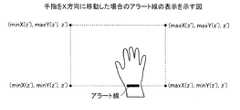
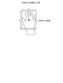
図9A〜図9Cは、操作者が、図9A→図9B→図9Cの順で右方向(X軸プラス方向)に移動した場合の図である。破線は、手指のZ座標におけるXY座標の3次元計測可能領域を示す。なお、この破線は、実際にはプロジェクタ3による表示は行われない線である。また、図9A〜図9Cでは、アラートパターンとしてアラート線が手指の一部に表示されている。アラート線は特定の色(たとえば赤や緑)の線分で、プロジェクタにより手指に照射表示される。図9Aでは、手指上のminY(z)を示す位置にアラート線が表示される。図9Bでは、minY(z)に加えmaxX(z)を示す線分も表示される。図9Cでは、maxX(z)を示す線分が表示される。線分を表示する際には、手指の3次元座標(x,y,z)から、3次元計測可能領域のX方向の最小値minX(z)までの距離distX1、最大値maxX(z)までの距離distX2を求める。distX1は、式「distX1=x−minX(z)」により求めることができる。また、distX2は、式「distX2=maxX(z)−x」により求めることができる。なお、手指の3次元座標は、たとえば図12で例示するように、撮影画像中の手指の領域の中心座標について、3次元計測を行った座標とする。図12は、手指の中心座標を示す図である。 9A to 9C are diagrams when the operator moves rightward (X-axis plus direction) in the order of FIG. 9A → FIG. 9B → FIG. 9C. A broken line indicates a three-dimensional measurable region of the XY coordinate in the Z coordinate of the finger. This broken line is a line that is not actually displayed by the
そして、distX1<Sx/2+M1、または、distX2<Sx/2+M2となる場合に縦線のアラート線を表示することを決定する。M1、M2はマージンであり、0以上のプラスの固定値である。 Then, when distX1 <Sx / 2 + M1 or distX2 <Sx / 2 + M2, it is determined to display a vertical alert line. M1 and M2 are margins, which are positive fixed values of 0 or more.
アラート線はdistX1<Sx/2+M1の場合には、点1(x−Sx/2+distX1×C1,y−Sy/2,z)、点2(x−Sx/2+distX1×C1,y+Sy/2,z)の2点を結ぶ線分として決めることができる。また、distX2<Sx/2+M2の場合、点1(x+Sx/2−distX2×C2,y−Sy/2,z)、点2(x+Sx/2−distX2×C2,y+Sy/2,z)の2点を結ぶ線分として表示位置を決めることができる。 When distX1 <Sx / 2 + M1, the alert line is point 1 (x−Sx / 2 + distX1 × C1, y−Sy / 2, z), point 2 (x−Sx / 2 + distX1 × C1, y + Sy / 2, z) Can be determined as a line segment connecting the two points. Further, when distX2 <Sx / 2 + M2, two points of point 1 (x + Sx / 2−distX2 × C2, y−Sy / 2, z) and point 2 (x + Sx / 2−distX2 × C2, y + Sy / 2, z) The display position can be determined as a line segment connecting.
C1、C2は係数で、たとえばC1=(Sx/2)/(Sx/2+M1)、C2=(Sx/2)/(Sx/2+M2)と規定できる。このようにして決定したアラート線は、手指を3次元計測可能領域の右端(Xプラス方向)に近づけるにつれ、手指の右側から出現し、左側へ移動していく。手指の一番左までアラート線が移動すると、3次元計測可能領域から外れる。逆に、手指を3次元計測可能領域の左端(Xマイナス方向)に近づけるにつれ、アラート線が手指の左側から出現し、右側へ移動していく、手指の一番右までアラート線が移動すると、3次元計測可能領域から外れる。なお、Y方向のアラート線の長さについては、手からはみ出さないよう短く設定してもよい。 C1 and C2 are coefficients, and can be defined as C1 = (Sx / 2) / (Sx / 2 + M1), C2 = (Sx / 2) / (Sx / 2 + M2), for example. The alert line determined in this way appears from the right side of the finger and moves to the left side as the finger approaches the right end (X plus direction) of the three-dimensionally measurable region. When the alert line moves to the leftmost of the finger, it deviates from the 3D measurable area. Conversely, as the finger moves closer to the left end of the 3D measurable area (X minus direction), the alert line appears from the left side of the finger and moves to the right side. Depart from the 3D measurable area. Note that the length of the alert line in the Y direction may be set short so as not to protrude from the hand.
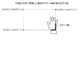
図10A〜図10Cは、操作者が、図10A→図10B→図10Cの順で手前方向(Y軸マイナス方向)に移動した場合の図である。図10A〜図10Cに例示するように、手指上のminY(z)を示す位置にアラート線が表示されるが、手指の移動に合わせてアラート線も手首側から指先側へと移動する。線分を表示する際には、手指の3次元座標(x,y,z)から、3次元計測可能領域のY方向の最小値までの距離distY1、最大値までの距離distY2を求める。distY1は、式「distY1=y−minY(z)」により求めることができ、distY2は、式「distY2=maxY(z)−y」により求めることができる。 10A to 10C are diagrams when the operator moves in the front direction (Y-axis minus direction) in the order of FIG. 10A → FIG. 10B → FIG. 10C. As illustrated in FIGS. 10A to 10C, an alert line is displayed at a position indicating minY (z) on the finger. The alert line also moves from the wrist side to the fingertip side as the finger moves. When displaying the line segment, the distance distY1 from the three-dimensional coordinates (x, y, z) of the finger to the minimum value in the Y direction of the three-dimensional measurable region and the distance distY2 to the maximum value are obtained. distY1 can be obtained from the expression “distY1 = y−minY (z)”, and distY2 can be obtained from the expression “distY2 = maxY (z) −y”.
そして、ここで、表示部153は、distY1<Sy/2+M1、または、distY2<Sy/2+M2となる場合に、縦線のアラート線を表示することを決定する。また、アラート線は、distY1<Sy/2+M1の場合に、点1(x−Sx/2,y−Sy/2+distY1×C1,z)、点2(x+Sx/2,y−Sy/2+distY1×C1,z)の2点を結ぶ線分である。また、アラート線は、distY2<Sy/2+M2の場合、点1(x−Sx/2,y+Sy/2−distY2×C2,z)、点2(x+Sx/2,y+Sy/2−distY2×C2,z)の2点を結ぶ線分として表示位置を決めることができる。C1、C2は係数で、たとえば、C1=(Sy/2)/(Sy/2+M1)、C2=(Sy/2)/(Sy/2+M2)と規定できる。 Here, the
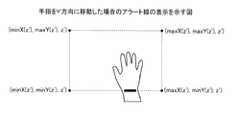
図11A〜図11Cは、操作者が、図11A→図11B→図11Cの順で上方向(Z軸マイナス方向)に移動した場合の図である。図10A〜図10Cに例示するように、手指上のminY(z)を示す位置にアラート線が表示されるが、手指の移動に合わせてアラート線も手首側から指先側へと移動する。 11A to 11C are diagrams when the operator moves upward (Z-axis minus direction) in the order of FIG. 11A → FIG. 11B → FIG. 11C. As illustrated in FIGS. 10A to 10C, an alert line is displayed at a position indicating minY (z) on the finger. The alert line also moves from the wrist side to the fingertip side as the finger moves.
Z軸については、手指の3次元座標からminZまでの距離distZ=−minZを元に判定する。maxZは、カメラからテーブル面までの距離であり、テーブル面より下に手指が存在することはないため、最大値については考慮しなくてよい。 The Z axis is determined based on the distance distZ = −minZ from the three-dimensional coordinates of the finger to minZ. maxZ is the distance from the camera to the table surface, and since there is no finger below the table surface, the maximum value need not be considered.
そして、M3を0より大きい固定値とすると、distZ<M3となる場合にアラート線を表示するようにする。なお、プロジェクタによる手指へのアラート線表示は、2次元であり、縦横線としてあらわせるため、Z軸は縦横線のどちらかに割り当てて、動かす。たとえば、min(a,b)をa,bの小さいほうの値を返す式とする。そして、min(distX1,distX2)<min(distY1,distY2)ならば、縦線で、点1(x−Sx/2+distZ×C3,y−Sy/2,z)、点2(x−Sx/2+distZ×C3,y+Sy/2,z)の2点を結ぶ線分として表示する。 If M3 is a fixed value larger than 0, an alert line is displayed when distZ <M3. The alert line displayed on the finger by the projector is two-dimensional and is displayed as vertical and horizontal lines. Therefore, the Z axis is assigned to either the vertical or horizontal line and moved. For example, let min (a, b) be an expression that returns the smaller value of a and b. If min (distX1, distX2) <min (distY1, distY2), the vertical lines are point 1 (x−Sx / 2 + distZ × C3, y−Sy / 2, z), point 2 (x−Sx / 2 + distZ). XC3, y + Sy / 2, z) and displayed as a line segment connecting the two points.
ここで、表示部153は、min(distX1,distX2)≧min(distY1,distY2)ならば、横線で、点1(x−Sx/2,y−Sy/2+distZ×C3,z)、点2(x+Sx/2,y−Sy/2+distZ×C3,z)の2点を結ぶ線分として表示する。 Here, if min (distX1, distX2) ≧ min (distY1, distY2), the
表示部153は、X、Y方向のどちらもアラート線を表示する条件を満たした場合には縦横のアラート線を両方表示する。また、表示部153は、Z方向もアラート線を表示する条件を満たした場合には、Z軸に割り当てられた縦線または横線とX,Y軸の縦線または横線の両方あるいはどちらかを表示する。 The
また、表示部153は、アラートパターンとして、線ではなく円や矩形などの図形を使用することもできる。この場合には、distX1,distX2,distY1,distY2,distZに比例/反比例させて表示色の濃度や色、手指上の表示サイズを変更してもよい。図13A〜図13Cの例は、手指をXプラス方向へ移動した場合のアラート円の表示例である。表示部153は、3次元計測可能領域の端に近づくにつれ、表示色の濃度を落としたアラートパターンを生成する。また、表示部153は、手指が3次元計測可能領域の端に近づくにつれ、異なる表示色のアラートパターンを生成して表示してもよい。例えば、手指と3次元計測可能領域の境界が所定の距離以上離れている場合には、青のアラートパターンを生成し、手指と3次元計測可能領域の境界との距離が所定の距離未満である場合には、赤のアラートパターンを生成し、表示するようにしてもよい。また、表示部153は、手指が3次元計測可能領域の端に近づくにつれ、サイズが大きくなるアラートパターンを生成して表示するようにしてもよい。 The
続いて、表示部153は、生成したアラートパターンを表示するようにプロジェクタ3を制御する。アラート線を表示する場合には、表示色をユーザの手に表示して視認可能な色、たとえば緑とする。また、線の太さについても視認可能な一定の太さを持つものとする。アラート線の表示位置については、3次元座標上で決定しているが、これをプロジェクタ3で表示可能な2次元座標に変換する必要がある。以下で3次元座標(a,b,c)からプロジェクタ座標(xp,yp)への変換について説明する。 Subsequently, the
プロジェクタ3のテーブル面から設置高さをLp、プロジェクタの水平画角αph、垂直画角αpvとし、プロジェクタの表示画素数横Spw、表示画素数縦Sphとする。プロジェクタのZ軸方向の距離cにおける横投影範囲Rph(c)はRph(c)=2×c×tan(αph/2)、縦投影範囲Rpv(c)はRpv(c)=2×c×tan(αpv/2)とあらわせる。そして投影範囲の3次元座標系でのX座標最小値が「minPX(c)=−Rph(c)/2」となり、X座標最大値が「maxPX(c)=Rph(c)/2」となり、Y座標最小値が「minPY(c)=−Rpv(c)/2」となり、Y座標最大値が「maxPY(c)=Rpv(c)/2」となる。The installation height from the table surface of the
XYの投影範囲がプロジェクタ座標系となるため、3次元座標系の高さcにおいて、プロジェクタ座標系の(0,0)は、3次元座標(minPx(c),minPy(c),c)、プロジェクタ座標(Spw,Sph)は、3次元座標(maxPx(c),maxPy(c),c)に相当する。これをもとに、以下の(3)式、(4)式でxp,ypをa,b,cを用いて表すことができる。 Since the projection range of XY is the projector coordinate system, at the height c of the three-dimensional coordinate system, (0, 0) of the projector coordinate system is three-dimensional coordinates (minPx (c), minPy (c), c), The projector coordinates (Spw, Sph) correspond to three-dimensional coordinates (maxPx (c), maxPy (c), c). Based on this, xp and yp can be expressed using a, b, and c in the following equations (3) and (4).
このようにして求めた3次元座標(a,b,c)をプロジェクタ座標(xp,yp)に変換し、xp,ypに表示パターンを出力することにより、手指にアラートパターンを表示する。なお、xp<0またはyp<0またはxp≧Spwまたはyp≧Sphの場合にはアラートパターンは表示されない。以上のようにして、アラートパターンをユーザの手指に表示する。最後に、表示部153において、対象物への照射色の変更など、ジェスチャに応じたアプリケーションの表示を実施する。以上の処理はカメラ1、2から画像が取得される毎に実施される。 The three-dimensional coordinates (a, b, c) thus obtained are converted into projector coordinates (xp, yp), and the display pattern is output to xp, yp, thereby displaying the alert pattern on the finger. Note that no alert pattern is displayed when xp <0 or yp <0, or xp ≧ Spw or yp ≧ Sph. As described above, the alert pattern is displayed on the user's finger. Finally, the
[情報処理装置による処理]
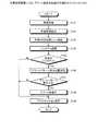
次に、図14を用いて、実施例1に係る情報処理装置10による処理を説明する。図14は、情報処理装置による、アラート線表示処理の手順を示すフローチャートである。[Processing by information processing device]
Next, processing performed by the
図14に示すように、情報処理装置10の取得部151は、カメラ1、2により撮像された撮影画像を取得する(ステップS101)。例えば、取得部151は、毎秒60回、2台のカメラ1、2からの画像を取得する。続いて、取得部151は、撮影画像の中から手指領域のみを検出する。 As illustrated in FIG. 14, the
そして、取得部151は、撮影画像の中から手指領域のみを抽出する(ステップS102)。例えば、取得部151は、画像における各画素の色情報、および抽出するための色に関する条件に基づき、肌色領域を検出し、撮影画像の中から手指領域のみを抽出する。 Then, the
続いて、計側部152は、取得部151によって取得された撮影画像に含まれる手指の3次元座標位置(x,y,z)を検出する(ステップS103)。そして、計測部152は、検出した手指領域の形状や過去の手指領域の形状からの変化をもとにジェスチャを認識する(ステップS104)。 Subsequently, the
そして、計測部152は、所定のジェスチャであるか否かを判定する(ステップS105)。例えば、計測部152は、選択操作や決定操作などの操作に関するジェスチャであるか否かを判定する。この結果、計測部152によって所定のジェスチャでないと判定した場合、つまり、操作と関係ないジェスチャであると判定された場合には(ステップS105否定)、表示部153は、アプリケーションの表示を実施する(ステップS109)。 Then, the
また、計測部152によって所定のジェスチャであると判定した場合、つまり、操作に関係するジェスチャであると判定された場合には(ステップS105肯定)、表示部153は、アラートパターンの表示位置を決定する(ステップS106)。そして、表示部153は、アラートパターンを表示するか否かを判定する(ステップS107)。例えば、表示部153は、手指の3次元座標が、3次元計測可能領域の境界に近づいたか否かに応じて、アラートパターンを表示するか否かを判定する。 When the
この結果、表示部153は、アラートパターンを表示しないと判定した場合には(ステップS107否定)、アプリケーションの表示を実施する(ステップS109)。また、表示部153は、アラートパターンを表示しないと判定した場合には(ステップS107肯定)、アラート線を表示し(ステップS108)、アプリケーションの表示を実施する(ステップS109)。 As a result, when it is determined that the alert pattern is not displayed (No at Step S107), the
[実施例1の効果]
上述してきたように、情報操作表示システム100は、カメラ1、2とプロジェクタ3と情報処理装置10とを有する。この情報処理装置10は、カメラ1、2により撮像された撮影画像を取得し、取得された撮影画像に含まれる操作対象物の3次元座標位置を計測する。そして、情報処理装置10は、計測された3次元座標位置と、カメラ1、2により定まる、手指の3次元座標位置が計測可能な3次元領域の境界との距離に基づいて、手指に画像を表示するようにプロジェクタを制御する。このため、情報処理装置10は、操作性を向上させることが可能である。[Effect of Example 1]
As described above, the information
また、手指が3次元計測可能領域から外れる前に、手指上にアラートパターンが表示され、その表示状態により、同じ動きを続けると手指が検出領域から外れそうかについてユーザは認知できる。その結果、ユーザは計測可能領域から外すことなく手指を動かすことができる。また、アラート表示を手指に行うことで、ユーザは手指を見るだけで直感的にわかり、紙面や対象物への表示には影響を与えない効果もある。 In addition, an alert pattern is displayed on the finger before the finger moves out of the three-dimensionally measurable region, and the user can recognize whether the finger is likely to move out of the detection region if the same movement is continued depending on the display state. As a result, the user can move the finger without removing it from the measurable area. Further, by performing alert display on the fingers, the user can intuitively understand by simply looking at the fingers, and there is an effect that does not affect the display on the paper or the object.
また、実施例1によれば、情報処理装置10は、過去の操作対象物の3次元座標位置と現在の操作対象物の3次元座標位置とを比較し、該3次元座標位置の変化に基づいて、操作対象物の3次元座標位置を予測する。そして、情報処理装置10は、予測された操作対象物の3次元座標位置と、3次元領域の境界との距離に基づいて、操作対象物に画像を表示するようにプロジェクタ3を制御する。このため、情報処理装置10は、手指の3次元座標を予測し、移動先に合わせた表示を行うと、意図した位置にずれなく後述するアラートパターンを表示することができる。 According to the first embodiment, the
また、実施例1によれば、情報処理装置10は、手指の3次元座標位置に応じて表示態様が変化する3次元領域の境界を示唆する縦線または横線を、操作対象物に表示するようにプロジェクタを制御する。このため、情報処理装置10は、3次元領域を把握させ、ユーザは計測可能領域から外すことなく手指を動かすことが可能である。 In addition, according to the first embodiment, the
また、実施例1によれば、情報処理装置10は、手指の3次元座標位置と3次元領域の境界との距離に応じて色が変化する図形を、手指に表示するようにプロジェクタ3を制御する。このため、情報処理装置10は、色の変化により、計測可能領域から外れそうか否かをユーザに対して分かりやすく報知することができる。 Further, according to the first embodiment, the
また、実施例1によれば、情報処理装置10は、手指の3次元座標位置と3次元領域の境界との距離に応じて濃淡が変化する図形を、手指に表示するようにプロジェクタ3を制御する。このため、情報処理装置10は、濃淡の変化により、計測可能領域から外れそうか否かをユーザに対して簡易に報知することができる。 Further, according to the first embodiment, the
また、実施例1によれば、情報処理装置10は、手指の3次元座標位置と3次元領域の境界との距離に応じて表示サイズが変化する図形を、手指に表示するようにプロジェクタ3を制御する。このため、情報処理装置10は、図形の表示サイズの変化により、計測可能領域から外れそうか否かをユーザに対して簡易に報知することができる。 Further, according to the first embodiment, the
また、実施例1によれば、情報処理装置10は、手指による特定のジェスチャが検出された場合に、計測された手指の3次元座標位置と、3次元領域の境界との距離に基づいて、画像を手指に表示するようにプロジェクタ3を制御する。このため、情報処理装置10は、特定のジェスチャが検出されない場合には、画像の表示制御を行わないので、処理負荷を軽減することが可能である。 In addition, according to the first embodiment, the
また、実施例1によれば、情報処理装置10は、起動しているアプリケーションが特定の状態である場合に、計測された手指の3次元座標位置と、3次元領域の境界との距離に基づいて、画像を手指に表示するようにプロジェクタ3を制御する。このため、情報処理装置10は、起動しているアプリケーションが特定の状態でない場合には、画像の表示制御を行わないので、処理負荷を軽減することが可能である。 Further, according to the first embodiment, the
さて、これまで開示のシステムに関する実施例について説明したが、開示の技術は上述した実施例以外にも、種々の異なる形態にて実施されてよいものである。そこで、以下では、本発明に含まれる他の実施例を説明する。 Although the embodiments related to the disclosed system have been described above, the disclosed technology may be implemented in various different forms other than the above-described embodiments. Therefore, another embodiment included in the present invention will be described below.
(1)単眼カメラ
上記の実施例1では、カメラ2台で手指などを撮影するステレオカメラの例を説明したが、これに限定されるものではなく、カメラ1台で手指などを撮影する単眼カメラでもよい。ここで、図15を用いて、単眼カメラである場合の情報操作表示システム100Aのハードウェア構成について説明する。図15は、単眼カメラである場合の情報操作表示システムのハードウェア構成を示す図である。(1) Monocular Camera In the first embodiment described above, an example of a stereo camera that captures fingers and the like with two cameras has been described. However, the present invention is not limited to this, and a monocular camera that captures fingers and the like with one camera. But you can. Here, the hardware configuration of the information
図15に示すように、情報操作表示システム100Aでは、テーブル5上に設置された装置で単眼カメラとして1台のカメラ1およびプロジェクタ3が固定台4により固定されている。1台のカメラ1およびプロジェクタ3は、実施例1と同様に、有線または無線でコンピュータに接続されている。 As shown in FIG. 15, in the information
また、図15に示すように、カメラ1は、テーブル面からLcの高さに、テーブル面と並行に設置されている。プロジェクタ3は、カメラ1の中央にテーブル面からLpの高さで設置されている。 Further, as shown in FIG. 15, the
次に、図16を用いて、単眼カメラの場合の3次元計測可能領域について説明する。図16は、単眼カメラである場合の3次元計測可能領域を示す図である。図16に示すように、カメラ1からテーブル面までの3次元の視野は、四角錐の形状になり、四角錐内の一定エリアのみが3次元計測可能領域となる。 Next, a three-dimensional measurable area in the case of a monocular camera will be described with reference to FIG. FIG. 16 is a diagram illustrating a three-dimensional measurable region in the case of a monocular camera. As shown in FIG. 16, the three-dimensional field of view from the
また、3次元計測可能領域は、1台のカメラ1の視野範囲となる。このため、レンズからのZ軸方向の距離zにおけるX,Y方向の3次元計測可能領域は、「X座標最小値 minX(z)=−(Rh(z)/2」、「X座標最大値 maxX(z)=(Rh(z)/2」、「Y座標最小値 minY(z)=−Rv(z)/2」、「Y座標最小値 minY(z)=Rv(z)/2」の範囲の座標としてあらわせる。また、3次元計測可能領域のZ座標最大値は、テーブル面となるため、「Z座標最大値 maxZ=Lc」となる。また、3次元計測可能領域のZ座標最大値は、テーブル面となるため、「Z座標最大値 maxZ=Lc」となる。Z座標最小値は、「Z座標最小値 minZ=Sy/(2×tan(αcv/2))」となる。Further, the three-dimensional measurable area is a visual field range of one
(2)視野範囲
また、上記の実施例1では、視野範囲が四角である場合の例を説明したが、これに限定されるものではなく、視野範囲が円であってもよい。ここで、図17を用いて、視野範囲が円である場合における3次元計測可能領域について説明する。図17は、視野範囲が円で取得可能なステレオカメラの3次元計測可能領域を示す図である。図17に示すように、カメラの画角をαとすると、レンズからのZ軸方向の距離zにおける視野範囲R(z)は、「R(z)=2×z×tan(α/2)」となる。(2) Field-of-view range Moreover, in said Example 1, although the example in case a field-of-view range was a square was demonstrated, it is not limited to this, A field-of-view range may be a circle. Here, the three-dimensional measurable region when the visual field range is a circle will be described with reference to FIG. FIG. 17 is a diagram illustrating a three-dimensionally measurable region of a stereo camera that can be acquired with a circular field of view range. As shown in FIG. 17, when the angle of view of the camera is α, the visual field range R (z) at the distance z in the Z-axis direction from the lens is “R (z) = 2 × z × tan (α / 2)”. "
この視野範囲をもとに、3次元計測可能領域は、2台のカメラ1、2の視野範囲が重なる場所としてあらわせる。このため、レンズからのZ軸方向の距離zにおけるX,Y方向の3次元計測可能領域は、「X座標最小値 minX(z)=−(Rh(z)−D)/2」、「X座標最大値 maxX(z)=(Rh(z)−D)/2」、「Z座標最大値 maxZ=Lc」、「Z座標最小値 minZ=Sy/(2×tan(αcv/2))」となる。Based on this visual field range, the three-dimensional measurable region is represented as a place where the visual field ranges of the two
また、図18を用いて、Y座標の最大最小値について説明する。図18は、視野範囲が円で取得可能なステレオカメラの3次元計測可能領域におけるY座標の最大最小値について説明する図である。図18に示すように、視野範囲の半径rは、「r=z×tan(α/2)」でもとめられる。また、図18に示す角度θは、「θ=acos(D/(2×r)」でもとめられる。ここで「acos」とは、逆余弦(アークコサイン)の略である。このため、Y座標最大値は、「maxY(z)=tanθ×2/D」となり、Y座標最小値は、「minY(z)=−tanθ×2/D」となる。 Further, the maximum and minimum values of the Y coordinate will be described with reference to FIG. FIG. 18 is a diagram for explaining the maximum and minimum values of the Y coordinate in the three-dimensional measurable region of the stereo camera that can be acquired with a circular field of view. As shown in FIG. 18, the radius r of the visual field range can also be determined by “r = z × tan (α / 2)”. 18 can also be obtained by “θ = acos (D / (2 × r)”, where “acos” is an abbreviation for arc cosine. The maximum coordinate value is “maxY (z) = tan θ × 2 / D”, and the minimum Y coordinate value is “minY (z) = − tan θ × 2 / D”.
(3)システム構成等
また、図示した各装置の各構成要素は機能概念的なものであり、必ずしも物理的に図示の如く構成されていることを要しない。すなわち、各装置の分散・統合の具体的状態は図示のものに限られず、その全部または一部を、各種の負荷や使用状況などに応じて、任意の単位で機能的または物理的に分散・統合して構成することができる。例えば、図3に示す取得部151、計測部152、表示部153の各処理部が適宜統合または分割されてもよい。また、各処理部にて行なわれる各処理機能は、その全部または任意の一部が、CPUおよび該CPUにて解析実行されるプログラムにて実現され、あるいは、ワイヤードロジックによるハードウェアとして実現され得る。(3) System Configuration The components of the illustrated devices are functionally conceptual and need not be physically configured as illustrated. In other words, the specific state of distribution / integration of each device is not limited to the one shown in the figure, and all or a part thereof may be functionally or physically distributed or arbitrarily distributed in arbitrary units according to various loads or usage conditions. Can be integrated and configured. For example, the processing units of the
(4)プログラム
また、上記の実施例で説明した各種の処理は、あらかじめ用意されたプログラムをパーソナルコンピュータやワークステーションなどのコンピュータシステムで実行することによって実現することもできる。そこで、以下では、上記の実施例と同様の機能を有するプログラムを実行するコンピュータシステムの一例を説明する。図19は、表示プログラムを実行するコンピュータを示す図である。(4) Program The various processes described in the above embodiments can also be realized by executing a program prepared in advance on a computer system such as a personal computer or a workstation. Therefore, in the following, an example of a computer system that executes a program having the same function as in the above embodiment will be described. FIG. 19 is a diagram illustrating a computer that executes a display program.
図19に示すように、コンピュータ300は、CPU310、ROM(Read Only Memory)320、HDD(Hard Disk Drive)330、RAM(Random Access Memory)340を有する。これら310〜340の各部は、バス400を介して接続される。 As illustrated in FIG. 19, the computer 300 includes a CPU 310, a ROM (Read Only Memory) 320, an HDD (Hard Disk Drive) 330, and a RAM (Random Access Memory) 340. These units 310 to 340 are connected via a
ROM320には上記実施例の各処理部と同様の機能を発揮する表示プログラム320aが予め記憶される。例えば、上記実施例の制御部15同様の機能を発揮する表示プログラム320aを記憶させる。なお、表示プログラム320aについては、適宜分離してもよい。 The
HDD330には、各種データを記憶する。例えば、HDD330は、OSや各種データを記憶する。 Various data are stored in the HDD 330. For example, the HDD 330 stores the OS and various data.
そして、CPU310が、表示プログラム320aをROM320から読み出して実行することで、実施例の各処理部と同様の動作を実行する。すなわち、表示プログラム320aは、実施例の制御部15と同様の動作を実行する。 Then, the CPU 310 reads the display program 320a from the
なお、上記した表示プログラム320aについては、必ずしも最初からROM320に記憶させることを要しない。表示プログラム320aはHDD330に記憶させてもよい。 The display program 320a is not necessarily stored in the
例えば、コンピュータ300に挿入されるフレキシブルディスク(FD)、Compact Disk Read Only Memory(CD−ROM)、Digital Versatile Disk(DVD)、光磁気ディスク、ICカードなどの「可搬用の物理媒体」にプログラムを記憶させておく。そして、コンピュータ300がこれらからプログラムを読み出して実行するようにしてもよい。 For example, a program is stored in a “portable physical medium” such as a flexible disk (FD), a compact disk read only memory (CD-ROM), a digital versatile disk (DVD), a magneto-optical disk, or an IC card inserted into the computer 300. Remember. Then, the computer 300 may read and execute the program from these.
さらには、公衆回線、インターネット、LAN、WANなどを介してコンピュータ300に接続される「他のコンピュータ(またはサーバ)」などにプログラムを記憶させておく。そして、コンピュータ300がこれらからプログラムを読み出して実行するようにしてもよい。 Furthermore, the program is stored in “another computer (or server)” connected to the computer 300 via a public line, the Internet, a LAN, a WAN, or the like. Then, the computer 300 may read and execute the program from these.
1,2 カメラ
3 プロジェクタ
10 情報処理装置
11 通信I/F部
12 表示部
13 入力部
14 記憶部
15 制御部
100 情報操作表示システム
141 3次元計測可能領域情報
142 3次元座標位置情報
143 アラートパターン情報
151 取得部
152 計側部
153 表示部DESCRIPTION OF
Claims (10)
Translated fromJapanese前記情報処理装置は、
前記カメラにより撮像された撮影画像を取得する取得部と、
前記取得部によって取得された撮影画像に含まれる操作対象物の3次元座標位置を計測する計測部と、
前記計測部によって計測された3次元座標位置と、前記カメラにより定まる、操作対象物の3次元座標位置が計測可能な3次元領域の境界との距離に基づいて、前記操作対象物に画像を表示するように前記プロジェクタを制御する表示部と、
を有することを特徴とする情報操作表示システム。An information operation display system having a camera, a projector, and an information processing device,
The information processing apparatus includes:
An acquisition unit for acquiring a captured image captured by the camera;
A measurement unit that measures the three-dimensional coordinate position of the operation target included in the captured image acquired by the acquisition unit;
An image is displayed on the operation target based on the distance between the three-dimensional coordinate position measured by the measurement unit and the boundary of a three-dimensional region determined by the camera and capable of measuring the three-dimensional coordinate position of the operation target. A display unit for controlling the projector to
An information operation display system comprising:
前記表示部は、前記計測部によって予測された操作対象物の3次元座標位置と、前記3次元領域の境界との距離に基づいて、前記操作対象物に画像を表示するように前記プロジェクタを制御することを特徴とする請求項1に記載の情報操作表示システム。The measurement unit compares the three-dimensional coordinate position of the previous operation target object with the three-dimensional coordinate position of the current operation target object, and determines the three-dimensional coordinate position of the operation target object based on the change in the three-dimensional coordinate position. Predict
The display unit controls the projector to display an image on the operation target based on a distance between a three-dimensional coordinate position of the operation target predicted by the measurement unit and a boundary of the three-dimensional region. The information operation display system according to claim 1, wherein:
前記撮影画像に含まれる操作対象物の3次元座標位置を計測し、
前記3次元座標位置と、前記カメラにより定まる、前記操作対象物の3次元座標位置が計測可能な3次元領域の境界との距離に基づいて、前記操作対象物に画像を表示するようにプロジェクタを制御する
処理をコンピュータに実行させることを特徴とする表示プログラム。Acquire a captured image captured by the camera,
Measure the three-dimensional coordinate position of the operation target included in the captured image,
Based on a distance between the three-dimensional coordinate position and a boundary of a three-dimensional region determined by the camera and capable of measuring the three-dimensional coordinate position of the operation target, a projector is displayed to display an image on the operation target. A display program that causes a computer to execute a controlling process.
前記撮影画像に含まれる操作対象物の3次元座標位置を計測し、
前記3次元座標位置と、前記カメラにより定まる、前記操作対象物の3次元座標位置が計測可能な3次元領域の境界との距離に基づいて、前記操作対象物に画像を表示するようにプロジェクタを制御する
ことを含んだことを特徴とする表示方法。Acquire a captured image captured by the camera,
Measure the three-dimensional coordinate position of the operation target included in the captured image,
Based on a distance between the three-dimensional coordinate position and a boundary of a three-dimensional region determined by the camera and capable of measuring the three-dimensional coordinate position of the operation target, a projector is displayed to display an image on the operation target. A display method characterized by including controlling.
Priority Applications (2)
| Application Number | Priority Date | Filing Date | Title |
|---|---|---|---|
| JP2013077240AJP6044426B2 (en) | 2013-04-02 | 2013-04-02 | Information operation display system, display program, and display method |
| US14/164,384US9645735B2 (en) | 2013-04-02 | 2014-01-27 | Information processing device and information processing method |
Applications Claiming Priority (1)
| Application Number | Priority Date | Filing Date | Title |
|---|---|---|---|
| JP2013077240AJP6044426B2 (en) | 2013-04-02 | 2013-04-02 | Information operation display system, display program, and display method |
Publications (2)
| Publication Number | Publication Date |
|---|---|
| JP2014203176A JP2014203176A (en) | 2014-10-27 |
| JP6044426B2true JP6044426B2 (en) | 2016-12-14 |
Family
ID=51620317
Family Applications (1)
| Application Number | Title | Priority Date | Filing Date |
|---|---|---|---|
| JP2013077240AExpired - Fee RelatedJP6044426B2 (en) | 2013-04-02 | 2013-04-02 | Information operation display system, display program, and display method |
Country Status (2)
| Country | Link |
|---|---|
| US (1) | US9645735B2 (en) |
| JP (1) | JP6044426B2 (en) |
Families Citing this family (15)
| Publication number | Priority date | Publication date | Assignee | Title |
|---|---|---|---|---|
| US9734582B2 (en)* | 2013-02-21 | 2017-08-15 | Lg Electronics Inc. | Remote pointing method |
| JP6047763B2 (en)* | 2014-09-03 | 2016-12-21 | パナソニックIpマネジメント株式会社 | User interface device and projector device |
| JP6103025B2 (en)* | 2014-12-22 | 2017-03-29 | キヤノンマーケティングジャパン株式会社 | Information processing apparatus, control method thereof, and program |
| US10482670B2 (en)* | 2014-12-30 | 2019-11-19 | Qingdao Goertek Technology Co., Ltd. | Method for reproducing object in 3D scene and virtual reality head-mounted device |
| CN104656902A (en)* | 2015-02-26 | 2015-05-27 | 华南理工大学 | Method and system for visual processing human-machine interactive projection based on Android |
| US10444006B2 (en) | 2015-08-19 | 2019-10-15 | Faro Technologies, Inc. | Three-dimensional imager |
| US10455216B2 (en)* | 2015-08-19 | 2019-10-22 | Faro Technologies, Inc. | Three-dimensional imager |
| EP3182250B1 (en)* | 2015-12-18 | 2019-10-30 | Aptiv Technologies Limited | System and method for monitoring 3d space in front of an output unit for the control of the output unit |
| WO2018042923A1 (en)* | 2016-08-31 | 2018-03-08 | ソニー株式会社 | Information processing system, information processing method, and program |
| CN108230383B (en)* | 2017-03-29 | 2021-03-23 | 北京市商汤科技开发有限公司 | Hand three-dimensional data determination method and device and electronic equipment |
| JP2019053769A (en)* | 2018-12-04 | 2019-04-04 | シャープ株式会社 | Touch detection apparatus, touch detection system, touch detection method, and program |
| CN110602358B (en)* | 2019-08-28 | 2021-06-04 | 维沃移动通信有限公司 | Image acquisition method and electronic equipment |
| CN112733577A (en)* | 2019-10-28 | 2021-04-30 | 富士通株式会社 | Method and device for detecting hand motion |
| JP6867464B2 (en)* | 2019-11-28 | 2021-04-28 | 株式会社ソニー・インタラクティブエンタテインメント | Information processing device and warning presentation method |
| EP4339746B1 (en)* | 2022-09-19 | 2024-09-04 | ameria AG | Touchless user-interface control method including time-controlled fading |
Family Cites Families (14)
| Publication number | Priority date | Publication date | Assignee | Title |
|---|---|---|---|---|
| US6463220B1 (en)* | 2000-11-08 | 2002-10-08 | Xerox Corporation | Method and apparatus for indicating a field of view for a document camera |
| JP3863809B2 (en) | 2002-05-28 | 2006-12-27 | 独立行政法人科学技術振興機構 | Input system by hand image recognition |
| US8972902B2 (en)* | 2008-08-22 | 2015-03-03 | Northrop Grumman Systems Corporation | Compound gesture recognition |
| JP4789885B2 (en)* | 2007-07-26 | 2011-10-12 | 三菱電機株式会社 | Interface device, interface method, and interface program |
| JP4991458B2 (en)* | 2007-09-04 | 2012-08-01 | キヤノン株式会社 | Image display apparatus and control method thereof |
| US8139110B2 (en)* | 2007-11-01 | 2012-03-20 | Northrop Grumman Systems Corporation | Calibration of a gesture recognition interface system |
| JP5347673B2 (en)* | 2009-04-14 | 2013-11-20 | ソニー株式会社 | Information processing apparatus, information processing method, and program |
| KR20100122383A (en)* | 2009-05-12 | 2010-11-22 | 삼성전자주식회사 | Method and apparatus for display speed improvement of image |
| JP4701424B2 (en)* | 2009-08-12 | 2011-06-15 | 島根県 | Image recognition apparatus, operation determination method, and program |
| GB2474536B (en)* | 2009-10-13 | 2011-11-02 | Pointgrab Ltd | Computer vision gesture based control of a device |
| JP5779923B2 (en)* | 2011-03-17 | 2015-09-16 | ソニー株式会社 | Information processing apparatus, information processing method, and computer program |
| JP2012208439A (en)* | 2011-03-30 | 2012-10-25 | Sony Corp | Projection device, projection method and projection program |
| JPWO2012173001A1 (en)* | 2011-06-13 | 2015-02-23 | シチズンホールディングス株式会社 | Information input device |
| US9210401B2 (en)* | 2012-05-03 | 2015-12-08 | Microsoft Technology Licensing, Llc | Projected visual cues for guiding physical movement |
- 2013
- 2013-04-02JPJP2013077240Apatent/JP6044426B2/ennot_activeExpired - Fee Related
- 2014
- 2014-01-27USUS14/164,384patent/US9645735B2/ennot_activeExpired - Fee Related
Also Published As
| Publication number | Publication date |
|---|---|
| US9645735B2 (en) | 2017-05-09 |
| JP2014203176A (en) | 2014-10-27 |
| US20140292723A1 (en) | 2014-10-02 |
Similar Documents
| Publication | Publication Date | Title |
|---|---|---|
| JP6044426B2 (en) | Information operation display system, display program, and display method | |
| JP6146094B2 (en) | Information operation display system, display program, and display method | |
| JP7632518B2 (en) | Image processing device, image processing method, and program | |
| JP6201379B2 (en) | Position calculation system, position calculation program, and position calculation method | |
| JP6723814B2 (en) | Information processing apparatus, control method thereof, program, and storage medium | |
| KR100851977B1 (en) | Controlling Method and apparatus for User Interface of electronic machine using Virtual plane. | |
| US10970807B2 (en) | Information processing apparatus and storage medium | |
| JP6344530B2 (en) | Input device, input method, and program | |
| CN107407959B (en) | Manipulation of three-dimensional images based on gestures | |
| US9035889B2 (en) | Information processing apparatus and information processing method | |
| WO2016103769A1 (en) | Manipulation input device, manipulation input method, and program | |
| JP6643825B2 (en) | Apparatus and method | |
| US20160292888A1 (en) | Image measurement device, and recording medium | |
| JP2012238293A (en) | Input device | |
| JP2017117373A (en) | Operating device, control method therefor, and program | |
| KR20150121069A (en) | Systems and methods for interactive image caricaturing by an electronic device | |
| JP6229554B2 (en) | Detection apparatus and detection method | |
| JP2014029656A (en) | Image processor and image processing method | |
| JP2016103137A (en) | User interface system, image processor and control program | |
| JP2016018458A (en) | Information processing system, control method therefore, program, and storage medium | |
| JP6632298B2 (en) | Information processing apparatus, information processing method and program | |
| JP6618301B2 (en) | Information processing apparatus, control method therefor, program, and storage medium | |
| CN111913564B (en) | Virtual content manipulation method, device, system, terminal equipment and storage medium | |
| US20240312134A1 (en) | User interface for adjusting bounding box dimensions in contactless measurement device | |
| JP2013257830A (en) | Information processor |
Legal Events
| Date | Code | Title | Description |
|---|---|---|---|
| A621 | Written request for application examination | Free format text:JAPANESE INTERMEDIATE CODE: A621 Effective date:20160113 | |
| A977 | Report on retrieval | Free format text:JAPANESE INTERMEDIATE CODE: A971007 Effective date:20161012 | |
| TRDD | Decision of grant or rejection written | ||
| A01 | Written decision to grant a patent or to grant a registration (utility model) | Free format text:JAPANESE INTERMEDIATE CODE: A01 Effective date:20161018 | |
| A61 | First payment of annual fees (during grant procedure) | Free format text:JAPANESE INTERMEDIATE CODE: A61 Effective date:20161031 | |
| R150 | Certificate of patent or registration of utility model | Ref document number:6044426 Country of ref document:JP Free format text:JAPANESE INTERMEDIATE CODE: R150 | |
| LAPS | Cancellation because of no payment of annual fees |